WO2021100436A1 - 操作デバイス - Google Patents
操作デバイス Download PDFInfo
- Publication number
- WO2021100436A1 WO2021100436A1 PCT/JP2020/040689 JP2020040689W WO2021100436A1 WO 2021100436 A1 WO2021100436 A1 WO 2021100436A1 JP 2020040689 W JP2020040689 W JP 2020040689W WO 2021100436 A1 WO2021100436 A1 WO 2021100436A1
- Authority
- WO
- WIPO (PCT)
- Prior art keywords
- noise
- audio signal
- operation device
- operating
- signal processing
- Prior art date
- Legal status (The legal status is an assumption and is not a legal conclusion. Google has not performed a legal analysis and makes no representation as to the accuracy of the status listed.)
- Ceased
Links
Images

Classifications
-
- G—PHYSICS
- G06—COMPUTING OR CALCULATING; COUNTING
- G06F—ELECTRIC DIGITAL DATA PROCESSING
- G06F3/00—Input arrangements for transferring data to be processed into a form capable of being handled by the computer; Output arrangements for transferring data from processing unit to output unit, e.g. interface arrangements
- G06F3/01—Input arrangements or combined input and output arrangements for interaction between user and computer
- G06F3/03—Arrangements for converting the position or the displacement of a member into a coded form
- G06F3/033—Pointing devices displaced or positioned by the user, e.g. mice, trackballs, pens or joysticks; Accessories therefor
-
- G—PHYSICS
- G10—MUSICAL INSTRUMENTS; ACOUSTICS
- G10L—SPEECH ANALYSIS TECHNIQUES OR SPEECH SYNTHESIS; SPEECH RECOGNITION; SPEECH OR VOICE PROCESSING TECHNIQUES; SPEECH OR AUDIO CODING OR DECODING
- G10L21/00—Speech or voice signal processing techniques to produce another audible or non-audible signal, e.g. visual or tactile, in order to modify its quality or its intelligibility
- G10L21/02—Speech enhancement, e.g. noise reduction or echo cancellation
- G10L21/0208—Noise filtering
- G10L21/0216—Noise filtering characterised by the method used for estimating noise
- G10L21/0224—Processing in the time domain
-
- A—HUMAN NECESSITIES
- A63—SPORTS; GAMES; AMUSEMENTS
- A63F—CARD, BOARD, OR ROULETTE GAMES; INDOOR GAMES USING SMALL MOVING PLAYING BODIES; VIDEO GAMES; GAMES NOT OTHERWISE PROVIDED FOR
- A63F13/00—Video games, i.e. games using an electronically generated display having two or more dimensions
- A63F13/20—Input arrangements for video game devices
- A63F13/21—Input arrangements for video game devices characterised by their sensors, purposes or types
- A63F13/215—Input arrangements for video game devices characterised by their sensors, purposes or types comprising means for detecting acoustic signals, e.g. using a microphone
-
- A—HUMAN NECESSITIES
- A63—SPORTS; GAMES; AMUSEMENTS
- A63F—CARD, BOARD, OR ROULETTE GAMES; INDOOR GAMES USING SMALL MOVING PLAYING BODIES; VIDEO GAMES; GAMES NOT OTHERWISE PROVIDED FOR
- A63F13/00—Video games, i.e. games using an electronically generated display having two or more dimensions
- A63F13/25—Output arrangements for video game devices
- A63F13/28—Output arrangements for video game devices responding to control signals received from the game device for affecting ambient conditions, e.g. for vibrating players' seats, activating scent dispensers or affecting temperature or light
- A63F13/285—Generating tactile feedback signals via the game input device, e.g. force feedback
-
- A—HUMAN NECESSITIES
- A63—SPORTS; GAMES; AMUSEMENTS
- A63F—CARD, BOARD, OR ROULETTE GAMES; INDOOR GAMES USING SMALL MOVING PLAYING BODIES; VIDEO GAMES; GAMES NOT OTHERWISE PROVIDED FOR
- A63F13/00—Video games, i.e. games using an electronically generated display having two or more dimensions
- A63F13/50—Controlling the output signals based on the game progress
- A63F13/54—Controlling the output signals based on the game progress involving acoustic signals, e.g. for simulating revolutions per minute [RPM] dependent engine sounds in a driving game or reverberation against a virtual wall
-
- G—PHYSICS
- G06—COMPUTING OR CALCULATING; COUNTING
- G06F—ELECTRIC DIGITAL DATA PROCESSING
- G06F3/00—Input arrangements for transferring data to be processed into a form capable of being handled by the computer; Output arrangements for transferring data from processing unit to output unit, e.g. interface arrangements
- G06F3/01—Input arrangements or combined input and output arrangements for interaction between user and computer
- G06F3/016—Input arrangements with force or tactile feedback as computer generated output to the user
-
- G—PHYSICS
- G06—COMPUTING OR CALCULATING; COUNTING
- G06F—ELECTRIC DIGITAL DATA PROCESSING
- G06F3/00—Input arrangements for transferring data to be processed into a form capable of being handled by the computer; Output arrangements for transferring data from processing unit to output unit, e.g. interface arrangements
- G06F3/01—Input arrangements or combined input and output arrangements for interaction between user and computer
- G06F3/03—Arrangements for converting the position or the displacement of a member into a coded form
- G06F3/033—Pointing devices displaced or positioned by the user, e.g. mice, trackballs, pens or joysticks; Accessories therefor
- G06F3/0338—Pointing devices displaced or positioned by the user, e.g. mice, trackballs, pens or joysticks; Accessories therefor with detection of limited linear or angular displacement of an operating part of the device from a neutral position, e.g. isotonic or isometric joysticks
-
- G—PHYSICS
- G10—MUSICAL INSTRUMENTS; ACOUSTICS
- G10L—SPEECH ANALYSIS TECHNIQUES OR SPEECH SYNTHESIS; SPEECH RECOGNITION; SPEECH OR VOICE PROCESSING TECHNIQUES; SPEECH OR AUDIO CODING OR DECODING
- G10L21/00—Speech or voice signal processing techniques to produce another audible or non-audible signal, e.g. visual or tactile, in order to modify its quality or its intelligibility
- G10L21/02—Speech enhancement, e.g. noise reduction or echo cancellation
- G10L21/0208—Noise filtering
- G10L21/0216—Noise filtering characterised by the method used for estimating noise
- G10L21/0232—Processing in the frequency domain
-
- H—ELECTRICITY
- H04—ELECTRIC COMMUNICATION TECHNIQUE
- H04R—LOUDSPEAKERS, MICROPHONES, GRAMOPHONE PICK-UPS OR LIKE ACOUSTIC ELECTROMECHANICAL TRANSDUCERS; ELECTRIC HEARING AIDS; PUBLIC ADDRESS SYSTEMS
- H04R1/00—Details of transducers, loudspeakers or microphones
- H04R1/08—Mouthpieces; Microphones; Attachments therefor
-
- H—ELECTRICITY
- H04—ELECTRIC COMMUNICATION TECHNIQUE
- H04R—LOUDSPEAKERS, MICROPHONES, GRAMOPHONE PICK-UPS OR LIKE ACOUSTIC ELECTROMECHANICAL TRANSDUCERS; ELECTRIC HEARING AIDS; PUBLIC ADDRESS SYSTEMS
- H04R3/00—Circuits for transducers
-
- G—PHYSICS
- G06—COMPUTING OR CALCULATING; COUNTING
- G06F—ELECTRIC DIGITAL DATA PROCESSING
- G06F2203/00—Indexing scheme relating to G06F3/00 - G06F3/048
- G06F2203/01—Indexing scheme relating to G06F3/01
- G06F2203/015—Force feedback applied to a joystick
-
- G—PHYSICS
- G10—MUSICAL INSTRUMENTS; ACOUSTICS
- G10L—SPEECH ANALYSIS TECHNIQUES OR SPEECH SYNTHESIS; SPEECH RECOGNITION; SPEECH OR VOICE PROCESSING TECHNIQUES; SPEECH OR AUDIO CODING OR DECODING
- G10L21/00—Speech or voice signal processing techniques to produce another audible or non-audible signal, e.g. visual or tactile, in order to modify its quality or its intelligibility
- G10L21/02—Speech enhancement, e.g. noise reduction or echo cancellation
- G10L21/0208—Noise filtering
- G10L2021/02082—Noise filtering the noise being echo, reverberation of the speech
-
- G—PHYSICS
- G10—MUSICAL INSTRUMENTS; ACOUSTICS
- G10L—SPEECH ANALYSIS TECHNIQUES OR SPEECH SYNTHESIS; SPEECH RECOGNITION; SPEECH OR VOICE PROCESSING TECHNIQUES; SPEECH OR AUDIO CODING OR DECODING
- G10L21/00—Speech or voice signal processing techniques to produce another audible or non-audible signal, e.g. visual or tactile, in order to modify its quality or its intelligibility
- G10L21/02—Speech enhancement, e.g. noise reduction or echo cancellation
- G10L21/0208—Noise filtering
- G10L21/0216—Noise filtering characterised by the method used for estimating noise
- G10L2021/02161—Number of inputs available containing the signal or the noise to be suppressed
- G10L2021/02163—Only one microphone
-
- H—ELECTRICITY
- H04—ELECTRIC COMMUNICATION TECHNIQUE
- H04R—LOUDSPEAKERS, MICROPHONES, GRAMOPHONE PICK-UPS OR LIKE ACOUSTIC ELECTROMECHANICAL TRANSDUCERS; ELECTRIC HEARING AIDS; PUBLIC ADDRESS SYSTEMS
- H04R2420/00—Details of connection covered by H04R, not provided for in its groups
- H04R2420/07—Applications of wireless loudspeakers or wireless microphones
Definitions
- the present invention relates to an operation device including a microphone and a voice signal processing method.
- Some operation devices that accept user operation input are equipped with a microphone that collects voice such as the user's voice.
- Such an operating device may perform a noise removal process that removes noise from the audio signal collected by the microphone.
- the noise that is the target of the noise removal processing includes the operation sound generated by the user's operation on the operation member provided in the operation device and the operation sound generated by the operation of the mechanism such as the vibration mechanism built in the operation device. It may contain noise generated by itself. Sufficient studies have not been made on how to remove the noise generated from such an operating device itself.
- the present invention has been made in consideration of the above circumstances, and one of the purposes thereof is an operation device capable of effectively removing noise generated from the operation device itself from an audio signal collected by a microphone, and an audio.
- the purpose is to provide a signal processing method.
- the operation device is an operation device including a microphone, and is expected to generate noise and a noise removal unit that executes noise removal processing for removing noise from the sound collection voice signal collected by the microphone.
- the noise removal unit includes an output unit that outputs noise generation information indicating that when it is in an operating state, and the noise removal unit changes the content of the noise removal processing according to the output noise generation information. It is characterized by.
- the audio signal processing method is an audio signal processing method executed by an operating device including a microphone, and when the operating device is in an operating state in which noise is expected to be generated, noise generation indicating that fact is generated.
- the step of executing the noise removal process which includes a step of outputting information and a step of executing a noise removal process for removing noise from the sound collection voice signal collected by the microphone, the noise generation information is used. It is characterized in that the content of the noise removal process is changed accordingly.
- FIG. 1 is an overall configuration diagram of an audio signal processing system 1 including an operation device 10 according to the first embodiment of the present invention.
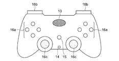
- FIG. 2 is a diagram showing an example of the appearance of the operation device 10.
- the audio signal processing system 1 includes an operation device 10 and an information processing device 50.
- the operation device 10 and the information processing device 50 transmit and receive data by wireless communication such as a Bluetooth (registered trademark) standard.
- wireless communication such as a Bluetooth (registered trademark) standard.
- data is transmitted and received by wireless communication, but the present invention is not limited to this, and the operation device 10 and the information processing device 50 may be connected by wire according to a standard such as USB.
- the operation device 10 is, for example, a controller for a home-use game machine, and includes a control circuit 11, an audio signal processing circuit 12, a speaker 13, a headphone terminal 14, a microphone 15, a plurality of operation members 16, and the like. It is configured to include a vibration mechanism 17 and a force sense presentation mechanism 18.
- the control circuit 11 is a microprocessor or the like, and executes a process for controlling each part of the operation device 10. Specifically, the control circuit 11 outputs a control signal for operating the vibration mechanism 17, the force sense presentation mechanism 18, and the like according to the control command received from the information processing device 50. Further, the state of each operation member 16 is periodically scanned to identify the operation content performed by the user, and an operation signal indicating the operation content is transmitted to the information processing device 50.
- control circuit 11 receives the reproduction audio signal from the information processing device 50, and transmits the reproduction audio signal to the audio signal processing circuit 12. Further, the sound collecting voice signal is received from the voice signal processing circuit 12, and the sound collecting voice signal is transmitted to the information processing device 50.
- control circuit 11 and the audio signal processing circuit 12 are connected to each other so as to be capable of data communication by an interface standard such as I2S (Inter-IC Sound).
- the audio signal processing circuit 12 is a digital signal processor or the like, and performs various signal processing on a digital audio signal. Specifically, the audio signal processing circuit 12 causes the reproduction audio signal received from the control circuit 11 to sound from the headphones or the speaker 13 connected to the headphone terminal 14. Further, the microphone 15 executes necessary audio signal processing on the collected audio signal and transmits it to the control circuit 11. In particular, in the present embodiment, the audio signal processing circuit 12 executes noise removal processing on the sound collecting audio signal using the information received from the control circuit 11. The details of this noise removal processing will be described later.
- the speaker 13 reproduces audio based on the reproduction audio signal output by the audio signal processing circuit 12.
- the audio signal processing circuit 12 may reproduce the sound based on the playback voice signal from the headphones instead of the speaker 13. it can.
- the microphone 15 collects sounds around the operating device 10, such as voice uttered by a user who uses the operating device 10.
- the microphone 15 may be a microphone array composed of a plurality of microphone elements.
- the plurality of operation members 16 are a kind of members for interaction with the user, and are members for receiving operation input by the user.
- the operating member 16 may include various members.
- the operation member 16 includes a plurality of push buttons 16a, a plurality of trigger buttons 16b capable of detecting a push amount, and a plurality of tilt operation members 16c operated by a user in a tilted manner.
- the push button 16a is a member that is pressed and operated by the user.
- the trigger button 16b is also a member that is pressed and operated by the user, but the pushing amount (operation amount) can be measured as a numerical value. This makes it possible to specify in more detail the content of the pressing operation, such as maintaining the state in which the user presses the trigger button 16b slightly, or pressing the trigger button 16b to the end quickly.
- the tilting operation member 16c is composed of a member protruding from the surface of the operating device 10, so that the user can operate the tilting operation member 16c by tilting it in any direction of 360 degrees.
- the control circuit 11 detects in what direction and how much the tilting operation member 16c is tilted. That is, the tilting operation member 16c can also measure the tilting amount as the user's operating amount. Further, by moving the tilting operation member 16c, the user can perform an operation input for instructing the direction.
- the vibration mechanism 17 is one of the members for interaction with the user.
- the vibration mechanism 17 is a device that generates vibration, and may be various devices such as a voice coil motor.
- the vibration mechanism 17 When the vibration mechanism 17 generates vibration in response to an instruction from the control circuit 11, the vibration is transmitted to the hand of the user holding the operating device 10.
- the operation device 10 may include a plurality of vibration mechanisms 17, and in that case, the plurality of vibration mechanisms 17 may be different types of vibration mechanisms.
- the force sense presentation mechanism 18 is one of the members for interaction with the user. Specifically, the force sense presentation mechanism 18 is a device that presents a force sense to the user when the user performs an operation on the operation member 16. In the present embodiment, the force sense presentation mechanism 18 is connected to the trigger button 16b, and when the user pushes the trigger button 16b, the force sense in the opposite direction to the pushing operation is presented.
- the force sense presentation mechanism 18 can control the content of the force sense to be presented according to the operation amount (push amount) of the trigger button 16b in response to the instruction from the control circuit 11. That is, as a result, the force sense presentation mechanism 18 presents the force sense to the user only while the operation amount of the trigger button 16b is included in the given value range, or the operation amount of the trigger button 16b is given. When the threshold value is exceeded, control such as ending the force sense presentation that has been executed up to that point may be realized.
- the information processing device 50 is, for example, a home-use game machine, a personal computer, or the like, and executes various processes using the operation signal and the voice signal received from the operation device 10. Further, a control command for operating the vibration mechanism 17 and the force sense presentation mechanism 18 and a reproduction voice signal for ringing from the speaker 13 and the like are transmitted to the operation device 10.
- the audio signal processing circuit 12 performs noise removal processing on the sound collecting audio signal collected by the microphone 15, and transmits the sound collecting audio signal to which the noise removal processing is applied to the control circuit 11. To do.
- the sound collecting voice signal is further transmitted to the information processing device 50 by the control circuit 11 and used for various processes.
- the sound collecting voice signal may include noise generated from the operation device 10 itself.
- each member used for interaction with the user such as the operation member 16, the vibration mechanism 17, and the force sense presentation mechanism 18, may generate noise when interacting with the user.
- noise includes noise generated when the user operates the operation member 16 (for example, sound generated when the push button 16a is pressed), and various mechanisms such as the vibration mechanism 17 and the force sense presentation mechanism 18. It may include noise generated by the operation of.
- the noise generated by the operating device 10 itself is referred to as device noise.
- the control circuit 11 determines whether or not the operating state of each member used for interaction with the user satisfies a given determination condition, and the noise generation information of the content according to the determination result. Is output and transmitted to the audio signal processing circuit 12.
- This given determination condition is a condition regarding whether or not the generation of device noise using these members as a noise source is expected. A specific example of such a determination condition will be described later.
- the control circuit 11 makes a determination for each of a plurality of determination conditions prepared in advance, and when it is determined that any of the determination conditions is satisfied, the control circuit 11 transmits noise generation information indicating that fact to the audio signal processing circuit 12. Further, if the determination condition is not satisfied, noise generation information indicating that fact may be transmitted. According to such control, it is possible to inform the audio signal processing circuit 12 of the generation timing of the device noise and the type of the generated device noise.
- the audio signal processing circuit 12 uses the noise generation information received from the control circuit 11 to execute noise removal processing having contents according to the device noise that is expected to be generated. Thereby, the accuracy of noise removal can be further improved.
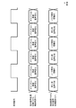
- FIG. 3 is a time chart schematically showing the contents of data transmitted / received between the control circuit 11 and the audio signal processing circuit 12.
- the upper part of FIG. 3 shows a synchronization signal, and voice data is exchanged between the control circuit 11 and the voice signal processing circuit 12 at a timing matched to the synchronization signal.
- the period of the synchronization signal may be determined according to the sampling rate of the transmitted / received audio signal.
- the middle part of FIG. 3 shows the contents of the voice data transmitted from the voice signal processing circuit 12 to the control circuit 11.
- the audio signal processing circuit 12 transmits data of a sound collecting audio signal after applying various audio signal processes including noise removal processing to the control circuit 11.
- the sound collecting sound signal is stereo sound data of two channels, and the sound collecting sound signal of channel 1 and the sound collecting sound signal of channel 2 are alternately transmitted in accordance with the synchronization signal.
- the lower part of FIG. 3 shows the contents of the data transmitted from the control circuit 11 to the audio signal processing circuit 12.
- the control circuit 11 transmits the data of the reproduction audio signal received from the information processing device 50 to the audio signal processing circuit 12.
- the playback audio signal is 1-channel monaural audio data. Therefore, the amount of data of the reproduction audio signal to be transmitted is one channel less than that of the sound collection audio signal. Therefore, the control circuit 11 includes the above-mentioned noise generation information in this empty channel and transmits it. Specifically, the control circuit 11 alternately transmits a channel reproduction audio signal and noise generation information. According to such control, noise generation information can be periodically notified to the audio signal processing circuit 12 by using a communication standard for audio signal transmission such as I2S without providing a separate communication channel.
- the control circuit 11 does not need to update the content of the noise generation information at the same time interval as the repetition period of the synchronization signal, updates the content of the noise generation information at a lower update frequency, and newly updates the content at the timing of updating the content.
- Noise generation information may be transmitted. Further, the control circuit 11 may transmit the content of the noise generation information when there is a change as a result of the update, and may not transmit the noise generation information when there is no change in the content. In this case, the audio signal processing circuit 12 executes noise removal processing based on the previously received content until new noise generation information is received. Further, the control circuit 11 does not need to transmit the entire noise generation information at once for each repetition period of the synchronization signal, and may be divided into a predetermined size and transmitted in a plurality of times.
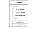
- FIG. 4 shows a specific example of the information included in the noise generation information output by the control circuit 11 and transmitted to the audio signal processing circuit 12.
- the noise generation information may include operation status information based on the operation input for each operation member 16. Further, the operation status information of the contents based on the operation status of various mechanisms included in the operation device 16 may be included.
- the operation status information is information indicating the judgment result regarding the presence / absence of the operation input by the user.
- the operation status information may include information indicating which operation member 16 the operation was performed on.
- information according to the determination result regarding the content of the operation on the operation member 16 may be included.
- the operation status information may include push button operation information.
- the push button operation information is information indicating that the push button 16a has been detected by the user.
- the push button operation information may include information indicating which push button 16a among the plurality of push buttons 16a is pressed. This is because it is assumed that the magnitude and frequency of device noise collected by the microphone 15 change depending on the type and position of the push button 16a.
- the device noise generated from the push button 16a is assumed to be generated at the timing when the push button 16a is pressed, and is not generated when the user keeps pressing the push button 16a or when the finger is released from the push button 16a. is assumed. Therefore, when the control circuit 11 detects that the user has performed an operation of pressing the push button 16a that has not been operated until then, the control circuit 11 notifies the audio signal processing circuit 12 of the push button operation information indicating that fact, and then notifies the voice signal processing circuit 12. May not notify the push button operation information even if it detects that the push button 16a is continuously pressed.
- the operation status information may include trigger button operation information.
- the trigger button operation information is information indicating that device noise is generated by the operation of the trigger button 16b by the user.
- the control circuit 11 may notify the noise generation information indicating that fact.
- the control circuit 11 determines whether or not the operation amount of the trigger button 16b has reached the maximum value or exceeds a predetermined threshold value in the vicinity of the maximum value, and at the timing when such a determination condition is satisfied, the control circuit 11 determines.
- the trigger button operation information indicating that fact may be notified to the audio signal processing circuit 12.
- the operation status information may include tilt operation member operation information.
- the tilting operation member operation information is information indicating that device noise is generated by the operation of the tilting operation member 16c by the user.
- the tilting operation member operation information may also be information indicating that the amount of operation of the tilting operation member 16c by the user satisfies a given determination condition.
- the control circuit 11 transmits the tilting operation member operation information indicating that fact.
- the tilting operation member 16c can be tilted 360 degrees in any direction.
- the position of the tilting operation member 16c being operated by the user is specified by the two-dimensional position coordinates.
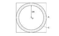
- FIG. 5 is a diagram for explaining the relationship between the operation content of the tilting operation member 16c and the device noise, and shows a range of values that the position coordinates can take.
- the center O of this coordinate space indicates a position (neutral position) in a state where the user is not operating the tilting operation member 16c. Therefore, the direction and distance from the center O of the detected position indicate in what direction and how much the tilting operation member 16c is tilted by the user.
- the movable range (operable range) of the tilting operation member 16c is regulated by a circular regulating member arranged around the tilting operation member 16c. Therefore, the detected position coordinates are limited to the range indicated by the circle C in FIG.
- the detection position of the tilting operation member 16c is located along the circumference of the circle C, it indicates that the tilting operation member 16c is tilted to the maximum amount and is in contact with the regulating member.
- the main device noise generated by the tilting operation member 16c is a collision sound generated by colliding with the regulating member when the tilting operation member 16c is tilted to the maximum amount. Therefore, the control circuit 11 may transmit the tilting operation member operation information indicating that to the audio signal processing circuit 12 only when it is assumed that the collision sound is generated.
- the control circuit 11 determines that the detection position of the tilting operation member 16c is in the outer peripheral region A shaded in FIG. 5, the control circuit 11 notifies the audio signal processing circuit 12 to that effect. I will do it.
- the tilting operation member 16c is located in the outer peripheral region A, it may collide with the regulating member to generate device noise, but when it is located at a position other than the outer peripheral region A (position from the center O), it is tilted. This is because there is no possibility that the operating member 16c collides with the regulating member, and it is not necessary to consider device noise due to the collision.
- the inside of the outer peripheral region A is an region where the distance from the center O is larger than the threshold value Dth.
- the control circuit 11 transmits the tilting operation member operation information indicating that noise may be generated when the operating amount of the tilting operation member 16c becomes larger than the threshold value Dth.
- the audio signal processing circuit 12 receives the sound collected at the exact timing when the device noise due to the collision is generated. , The noise removal process suitable for the noise can be executed.
- the control circuit 11 may transmit information indicating that noise may occur when the operation speed satisfies a given determination condition.
- the control circuit 11 may transmit information indicating that noise may occur when the operation speed satisfies a given determination condition.
- the threshold value Dth When the user is slowly operating the tilting operation member 16c, even if the operating amount of the tilting operation member 16c exceeds the threshold value Dth, it is unlikely that a large noise will be generated due to the collision with the regulating member. Further, even after the tilting operation member 16c collides with the regulating member and stops, it is not assumed that noise due to the collision is further generated.
- the control circuit 11 when the operation speed is equal to or less than the threshold value Vth, the control circuit 11 does not transmit the tilting operation member operation information indicating that noise may be generated, and the operation amount exceeds the threshold value Dth and is operated.
- the tilting operation member operation information may be transmitted only when a state in which the speed exceeds the threshold value Vth is detected. As a result, it becomes possible to execute the noise removal process more in line with the actual noise generation.
- the control circuit 11 may notify the audio signal processing circuit 12 of the tilting operation member operation information indicating such a state.
- the audio signal processing circuit 12 executes different types of noise removal processing according to the content of the notified tilting operation member operation information. As a result, more effective noise removal processing can be executed.
- the operating speed of the tilting operation member 16c can be calculated by specifying the amount of movement of the position of the tilting operation member 16c in the most recent predetermined period.
- the control circuit 11 calculates the amount of movement during that period as the operating speed from the changes in position obtained by sampling a plurality of times in the past. Thereby, it is possible to determine whether or not the operation speed exceeds the threshold value Vth.
- control circuit 11 may change the content of the tilting operation member operation information to be notified according to the operating direction (moving direction of the position of the tilting operating member 16c). For example, even if the tilting operation member 16c is located near the regulation member when the operation amount exceeds the threshold value Dth, if the position moves toward the center O, the tilting operation member 16c collides with or rubs against the regulation member and makes noise. Cannot be expected to occur. Therefore, the control circuit 11 operates the tilting operation member indicating that noise may be generated only when it is determined that the most recent tilting operation member 16c moves in the outer peripheral direction (direction approaching the regulation member). Information may be transmitted.
- the operation status information may include vibration mechanism operation information.
- the vibration mechanism operation information is information indicating a determination result regarding the operation state of the vibration mechanism 17. While the vibration mechanism 17 is operating, it is assumed that the operating sound is generated as device noise. Therefore, when the control circuit 11 starts outputting the control signal for operating the vibration mechanism 17, the control circuit 11 transmits the vibration mechanism operation information indicating that the vibration mechanism 17 is operating at that timing to the audio signal processing circuit 12. Further, at the timing when the operation of the vibration mechanism 17 is stopped, the vibration mechanism operation information indicating that effect is transmitted.
- the vibration mechanism operation information may include information indicating which vibration mechanism 17 is in operation. Further, the vibration mechanism operation information may include information indicating the content of the vibration, such as the strength and frequency of the vibration generated by the control circuit 11 in the vibration mechanism 17. This is because it is assumed that the magnitude and frequency of device noise included in the sound collecting voice signal change depending on the type of the vibration mechanism 17 that generates the vibration, the position in the operation device 10, the content of the vibration to be generated, and the like.
- the operation status information may include the force sense presentation mechanism operation information.
- the force sense presentation mechanism operation information is information indicating a determination result about the operation state of the force sense presentation mechanism 18.
- the force sense presentation mechanism 18 presents the force sense in response to the user's operation on the trigger button 16b. Therefore, even if the control circuit 11 receives an instruction from the information processing device 50 to control the operation of the force sense presentation mechanism 18, the force sense presentation mechanism 18 does not immediately start the force sense presentation, and the trigger button 16b When the user's operation on the device satisfies a given operating condition, the operation is started and the force sense is presented.
- the control circuit 11 determines that the condition for operating the force sense presentation mechanism 18 is satisfied, and the timing at which the force sense presentation mechanism 18 actually executes the force sense presentation. Then, the force sense presentation mechanism operation information indicating that effect is transmitted to the audio signal processing circuit 12. When the force sense presentation by the force sense presentation mechanism 18 is completed, the force sense presentation mechanism operation information indicating that fact is transmitted. Further, the control circuit 11 may include the content of the force sense to be presented (strength of the force sense, etc.) in the force sense presentation mechanism operation information.
- the audio signal processing circuit 12 receives the noise generation information including the contents as described above, and changes the contents of the noise removal processing applied to the sound collecting voice signal according to the contents. Specifically, while the noise generation information indicating the generation of device noise is not received, the normal noise removal process unrelated to the device noise is executed. When the noise generation information indicating that the push button 16a is pressed is received, the noise removal process for reducing the noise generated by the push button 16a is executed for the sound collecting voice signal acquired at that timing. To do. Similarly, when noise generation information indicating that the trigger button 16b is pressed to the maximum amount is received, a noise removal process for reducing the noise generated by the trigger button 16b is executed. Further, when the noise generation information indicating that the tilting operation member 16c is tilted to the maximum amount is received, the noise removal processing for reducing the noise generated by the collision between the tilting operation member 16c and the regulating member is executed.
- the audio signal processing circuit 12 executes a noise removal process for reducing the noise generated by the vibration mechanism 17.
- noise removal processing for reducing the noise is executed. In this way, by using the noise generation information transmitted by the control circuit 11 at the timing when device noise is expected to occur, the audio signal processing circuit 12 performs noise removal processing having contents suitable for the generated device noise in real time. Can be executed.
- the device noise generated by the operation device 10 itself can be effectively removed.
- the operation device 10 is a controller of a home-use game machine, but the present invention is not limited to this, and various devices including a microphone and an operation member to be operated by the user may be used.
- the operation device 10 is provided with three types of operation members 16: a push button 16a, a trigger button 16b, and a tilting operation member 16c.
- the operation device 10 also includes various types such as a touch pad.
- the operating member 16 of the above may be provided.
- the control circuit 11 provides the operating member operation information indicating that the operation on the operating member 16 has been accepted, as in the above description. It is transmitted to the audio signal processing circuit 12.
- the operation device 10 may include various mechanisms that may generate noise in addition to the vibration mechanism 17 and the force sense presentation mechanism 18. Also in this case, when operating these mechanisms, the control circuit 11 transmits the operation status information indicating the status to the audio signal processing circuit 12. As a result, the audio signal processing circuit 12 can perform appropriate noise removal processing.
- the control circuit 11 when it is determined that the operation device 10 is in an operating state in which noise is expected to be generated, the control circuit 11 indicates noise generation information to that effect. Is output and notified to the audio signal processing circuit 12. That is, it is decided that the control circuit 11 executes the noise generation determination process for determining whether or not the operation state is expected to generate noise.
- embodiments of the present invention are not limited to this.
- the hardware configuration of the entire audio signal processing system may be the same as that of the first embodiment described with reference to FIGS. 1 and 2. Therefore, each component constituting the system is referred to by using the same reference numerals as those in the first embodiment.
- the control circuit 11 periodically scans (scans) the operating state of each member of the operating device 10, and periodically transmits information (scan data) indicating the result to the information processing device 50. .. Then, this scan data is also transmitted to the audio signal processing circuit 12 at a predetermined timing.
- the audio signal processing circuit 12 determines whether or not the operating device 10 is in a state where noise is expected to be generated based on the scan data received from the control circuit 11, and outputs noise generation information according to the determination result. To do. That is, in the present embodiment, the audio signal processing circuit 12 executes the noise generation determination processing that the control circuit 11 has decided to perform in the above description, and outputs noise generation information indicating the execution result.
- the audio signal processing circuit 12 changes the content of the noise removal processing executed by itself according to the noise generation information output by itself, as in the case of the first embodiment. That is, in the present embodiment, the audio signal processing circuit 12 realizes the functions of both the noise removing unit and the output unit.
- each time the predetermined time T1 elapses the control circuit 11 scans the state of each operating member 16 at that time, and the obtained data is a buffer built in itself as one scan data. Record in memory.
- the time T1 is the execution cycle of the scan process.
- the scan data includes data indicating the operating state of each member of the operating device 10 for interaction with the user. Specifically, the scan data includes whether or not the push button 16a is pressed, how much the trigger button 16b is pressed, how much the tilting operation member 16c is tilted, and so on. It contains operation information indicating the operation content of the user with respect to 16. Further, the scan data may include information indicating an operating state of each member controlled by the control circuit 11, such as the vibration mechanism 17 and the force sense presentation mechanism 18.
- the control circuit 11 records not only the latest one but also N scan data obtained by the past N scan processes in the buffer memory. When a new scan process is executed with N scan data recorded, the control circuit 11 records the latest scan data in the buffer memory and erases the oldest scan data.
- the control circuit 11 transmits the latest scan data to the information processing device 50 every time T2 elapses for a predetermined time.
- the time T2 is a transmission cycle of scan data to the information processing apparatus 50, and is preferably time T1 or more.
- the information processing device 50 can know the state of the operation device 10 by referring to the scan data received from the control circuit 11 of the operation device 10, and can change the operation contents performed by the user and the operation state of each part of the operation device 10. The corresponding processing can be executed.
- the control circuit 11 When the time T2 is longer than the time T1, not all the scan data recorded periodically by the control circuit 11 is transmitted to the information processing device 50, and may not be transmitted to the information processing device 50 depending on the timing. Scan data may be generated. However, since the control circuit 11 always transmits the latest scan data (that is, acquired in the latest past), the information processing device 50 can execute processing according to the state of the latest operating device 10.
- the control circuit 11 collectively provides the audio signal processing circuit 12 with a plurality of scan data recorded in its own buffer memory in response to a request from the audio signal processing circuit 12. Specifically, the control circuit 11 writes a plurality of scan data to the buffer memory in the audio signal processing circuit 12 at a timing determined according to a transmission request received from the audio signal processing circuit 12. The details of this transmission request will be described later.
- the scan data to be written in the audio signal processing circuit 12 is all the scan data acquired after the scan data to be written last time.
- the writing from the control circuit 11 to the audio signal processing circuit 12 may be realized by, for example, communication based on the SPI (serial peripheral interface) standard.
- the audio signal processing circuit 12 continuously executes the sound collection audio signal acquisition process of converting the analog audio signal collected by the microphone 15 into a digital audio signal by the AD converter and acquiring the sound collection audio signal data. Then, every time the predetermined time T3 elapses, the echo cancellation process is executed for the sound collection voice signal data having a length of the time T3 minutes acquired in the past.
- the time T3 is the execution cycle of the echo cancellation process.
- the audio signal processing circuit 12 executes noise removal processing on the sound collecting audio signal data after the echo cancellation processing is executed every time the predetermined time T4 elapses.
- the time T4 is the execution cycle of the noise removal process.
- the time T4 is twice the time of the time T3
- the audio signal processing circuit 12 uses the sound collection audio signal data to be processed in the past two echo cancellation processes in one noise removal process. Target for processing.
- the time T4 is longer than the time T3 here, both may be the same time.
- the audio signal processing circuit 12 requests the control circuit 11 to transmit the next scan data at the timing of executing the noise removal processing.
- this transmission request is made by switching the high and low (H / L) of the voltage output to the GPIO (general purpose input / output) signal line (hereinafter referred to as control signal line). That is, the audio signal processing circuit 12 executes noise removal processing every time T4 elapses for a predetermined time, and changes the output voltage of the control signal line during the processing to obtain scan data for the control circuit 11. Make a transmission request.
- the control circuit 11 detects a change in the output voltage of the control signal line, the control circuit 11 writes the untransmitted scan data acquired up to that point in the buffer memory in the audio signal processing circuit 12 as described above. Therefore, the control circuit 11 periodically executes the writing process of writing the scan data to the audio signal processing circuit 12 with the time T4 as the execution cycle.
- the audio signal processing circuit 12 secures two storage areas for writing the scan data, and the control circuit 11 alternately writes the scan data to these two storage areas.
- the scan data transmitted by the control circuit 11 over the last two times can always be recorded in the audio signal processing circuit 12.
- the control circuit 11 writes the scan data to the buffer B1 when the output voltage of the control signal line is switched from L to H, and writes the scan data to the buffer B2 when the output voltage is switched from H to L.
- the old scan data recorded in the write destination buffer is overwritten and erased.
- the audio signal processing circuit 12 requests the control circuit 11 to write new scan data by switching the output voltage of one control signal line, and at the same time, the next writing destination.
- a buffer can be specified for the control circuit 11.
- the control circuit 11 collectively transmits a plurality of scan data acquired after the previous transmission of the scan data to the audio signal processing circuit 12.
- the time T1 execution cycle of the scan process
- the time T4 execution cycle of the noise removal process
- This time T4 corresponds to the time for sampling 256 samples of audio signals at a sampling rate of 24 kHz.
- the control circuit 11 transmits 10 or 11 scan data to the audio signal processing circuit 12 at a time. Send all at once.
- the 10 or 11 scan data will be stored in each of the buffers B1 and B2 in the audio signal processing circuit 12.
- the audio signal processing circuit 12 When executing the noise removal processing, the audio signal processing circuit 12 performs the noise removal processing using the scan data written by the control circuit 11 in response to the transmission request when the previous noise removal processing is executed. Specifically, first, the audio signal processing circuit 12 starts from a buffer B1 and B2 that is different from the buffer designated as the write destination this time (that is, the buffer designated as the write destination during the previous noise removal processing). Reads 10 or 11 scan data written by the control circuit 11.
- the audio signal processing circuit 12 executes noise generation determination processing for determining whether or not the operating device 10 is in an operating state in which noise is expected to be generated based on the read scan data, and makes the determination result noise. Output as occurrence information. Then, the noise removal processing is performed with the contents determined according to the output noise generation information.
- This noise generation determination process may be the same process as the process determined to be executed by the control circuit 11 in the first embodiment described above. Further, the noise removal process based on the noise generation information may be the same process as the process decided to be executed by the audio signal processing circuit 12 in the first embodiment.
- the audio signal processing circuit 12 by comparing the contents of the operation information included in the two time-continuous scan data, has the push button 16a, which has not been pressed until then, started to be pressed? Judge whether or not. If the scan data at a certain point in time indicates that a certain push button 16a is not pressed, but the scan data acquired at the next timing indicates that the same push button 16a is pressed, that is the case. It is determined that the push button 16a is pressed at the timing when the scan data is acquired. In such a case, there is a possibility that noise caused by pressing the push button 16a is generated at that timing.
- the audio signal processing circuit 12 uses a filter corresponding to the noise caused by pressing the push button 16a when executing the noise removal processing for the time interval corresponding to the time interval in which the read scan data is acquired. Then, a noise removal process capable of removing the noise is executed.
- the audio signal processing circuit 12 when scan data indicating that the operation amount of the trigger button 16b exceeds a predetermined threshold value Dth is acquired, the audio signal processing circuit 12 outputs noise generation information indicating that fact and removes noise according to the output. The process is to be executed. Similarly, when scan data indicating that the tilting operation member 16c has been operated up to the outer peripheral region A as illustrated in FIG. 5 is acquired, the audio signal processing circuit 12 may generate noise in the tilting operation member 16c. It is determined that there is, and noise removal processing is executed according to the output. Further, the audio signal processing circuit 12 may execute noise removal processing according to the content of the scan data indicating that the vibration mechanism 17 or the force sense presentation mechanism 18 is operating.
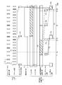
- FIG. 6 the processing for processing the scan data acquired immediately after this time tx and the sound collecting voice signal data acquired in the time interval including this time tx is shown by shading. There is. However, the shading for the buffer B1 indicates the period during which the target scan data is recorded in the buffer B1.
- scan data indicating that the push button 16a is pressed is generated in the scan process P1 executed immediately after that.
- the audio signal processing circuit 12 continuously executes the sound collecting audio signal acquisition process as described above.
- the audio signal processing circuit 12 executes echo cancellation processing on the collected audio signal data every time the audio signal data for 128 samples is acquired at a sampling rate of 24 kHz after the time T3 elapses.
- the audio signal processing circuit 12 does not immediately execute the echo cancel process on the sound collection audio signal data acquired in the latest past, but executes the noise removal process corresponding to the time T4 (that is, the execution of the noise removal process described later).
- the execution of the process is delayed by one cycle). That is, each time the time T3 elapses, the audio signal processing circuit 12 executes the echo cancellation process for the sound collection voice signal data acquired in the past for a period corresponding to the time T4.
- the audio signal processing circuit 12 performs the sound collecting sound acquired in the past by time T4 minutes from this period.
- the echo cancellation process P3 is executed for the signal data.
- the audio signal processing circuit 12 subsequently executes the noise removal process P4 on the sound collection audio signal data that has been the target of the echo cancellation process twice in the past.
- the audio signal processing circuit 12 executes the noise generation determination process using the scan data stored in the buffer B2, and changes the content of the noise removal process according to the result.
- the control circuit 11 is requested to transmit scan data by switching the output voltage of the control signal line from L to H.
- the control circuit 11 executes the scan data writing process P5 with the buffer B1 as the writing destination. This is a process of writing 10 scan data obtained by the 10 scan processes executed in the latest past including the scan process P1 to the buffer B1 in the audio signal processing circuit 12.
- the audio signal processing circuit 12 executes the next echo canceling process P6 at the time t4 after the time T3 has elapsed from the time t2, and further performs the echo canceling process P7 at the time t5 after the time T3 has elapsed from the time t4.
- the echo canceling process P7 is a process for targeting the sound collecting sound signal data acquired by the sound collecting sound signal acquisition process P2.
- the audio signal processing circuit 12 When the echo cancel process P7 ends at time t6, the audio signal processing circuit 12 subsequently executes the noise removal process P8 on the sound collection audio signal data to which the echo cancel process is applied in the echo cancel processes P6 and P7. .. At this time, the audio signal processing circuit 12 executes the noise generation determination process with reference to the ten scan data stored in the buffer B1, and changes the content of the noise removal process according to the result. That is, the noise removal processing P8 is a process for the sound collecting voice signal data acquired by the timing time T4 or more before the execution start time, and the sound collecting voice signal data is acquired. This process includes noise generation determination processing using scan data acquired during the period corresponding to the period.
- the scan data stored in the buffer B1 at the time of executing the noise removal process P8 includes the scan data acquired immediately after the time tx when the push button 16a is pressed. Therefore, the audio signal processing circuit 12 executes noise removal processing corresponding to noise that is assumed to be generated when the push button 16a is pressed in the noise removal processing P8. In this way, the audio signal processing circuit 12 requests the control circuit 11 for the next scan data each time the time T4 elapses, and executes noise generation determination processing using the scan data transmitted last time. Then, noise removal processing is performed on the sound collection voice signal data acquired before the time T4 or more. As a result, it is possible to execute noise removal processing corresponding to the expected noise on the sound collection voice signal data acquired at the timing when the noise is expected to occur.
- the audio signal processing circuit 12 which is a circuit for audio signal processing executes noise generation information output processing using the scan data provided by the control circuit 11. I tried to do it.
- the control circuit 11 outputs scan data (data including operation information including operation contents for each operation member 16 by the user) generated for transmission to the information processing device 50 as an audio signal. It may be provided to the processing circuit 12, and it is not necessary to duplicately execute the generation of the data provided to the information processing apparatus 50 and the generation of the data provided to the voice signal processing circuit 12.
Landscapes
- Engineering & Computer Science (AREA)
- Physics & Mathematics (AREA)
- Multimedia (AREA)
- General Engineering & Computer Science (AREA)
- Human Computer Interaction (AREA)
- Acoustics & Sound (AREA)
- Theoretical Computer Science (AREA)
- Signal Processing (AREA)
- General Physics & Mathematics (AREA)
- Health & Medical Sciences (AREA)
- Quality & Reliability (AREA)
- Audiology, Speech & Language Pathology (AREA)
- Computational Linguistics (AREA)
- Soundproofing, Sound Blocking, And Sound Damping (AREA)
- Selective Calling Equipment (AREA)
- Circuit For Audible Band Transducer (AREA)
- User Interface Of Digital Computer (AREA)
Abstract
マイクロホンが集音した集音音声信号からノイズを除去するノイズ除去処理を実行する操作デバイスであって、ノイズの発生が想定される動作状態にある場合に、その旨を示すノイズ発生情報を通知し、当該ノイズ発生情報に応じてノイズ除去処理の内容を変化させる操作デバイスである。
Description
本発明は、マイクロホンを備える操作デバイス、及び音声信号処理方法に関する。
ユーザーの操作入力を受け付ける操作デバイスの中には、ユーザーの声などの音声を集音するマイクロホンを備えるものがある。このような操作デバイスは、マイクロホンによって集音された音声信号に対してノイズを除去するノイズ除去処理を実行する場合がある。
ノイズ除去処理の対象となるノイズには、操作デバイスが備える操作部材に対するユーザーの操作によって生じる操作音や、操作デバイスに内蔵された振動機構などの機構が動作することによって生じる動作音など、操作デバイス自身から発生されるノイズが含まれることがある。このような操作デバイス自身から発生されるノイズをどのように除去すればよいかについて、十分な検討がされていない。
本発明は上記実情を考慮してなされたものであって、その目的の一つは、操作デバイス自身から発生するノイズをマイクロホンによって集音された音声信号から効果的に除去できる操作デバイス、及び音声信号処理方法を提供することにある。
本発明に係る操作デバイスは、マイクロホンを備える操作デバイスであって、前記マイクロホンが集音した集音音声信号からノイズを除去するノイズ除去処理を実行するノイズ除去部と、ノイズの発生が想定される動作状態にある場合に、その旨を示すノイズ発生情報を出力する出力部と、を含み、前記ノイズ除去部は、前記出力されるノイズ発生情報に応じて前記ノイズ除去処理の内容を変化させることを特徴とする。
本発明に係る音声信号処理方法は、マイクロホンを備える操作デバイスが実行する音声信号処理方法であって、前記操作デバイスがノイズの発生が想定される動作状態にある場合に、その旨を示すノイズ発生情報を出力するステップと、前記マイクロホンにより集音された集音音声信号からノイズを除去するノイズ除去処理を実行するステップと、を含み、前記ノイズ除去処理を実行するステップでは、前記ノイズ発生情報に応じて前記ノイズ除去処理の内容を変化させることを特徴とする。
以下、本発明の実施の形態について、図面に基づき詳細に説明する。
[第1実施形態]
図1は、本発明の第1実施形態に係る操作デバイス10を含む音声信号処理システム1の全体構成図である。また、図2は、操作デバイス10の外観の一例を示す図である。これらの図に示されるように、音声信号処理システム1は、操作デバイス10と情報処理装置50とを含んで構成されている。本実施形態において操作デバイス10と情報処理装置50とは、Bluetooth(登録商標)規格などの無線通信によってデータを送受信することとする。なお、ここでは無線通信によってデータの送受信を行うこととしているが、これに限らず操作デバイス10と情報処理装置50とは例えばUSB等の規格により有線で通信接続されることとしてもよい。
図1は、本発明の第1実施形態に係る操作デバイス10を含む音声信号処理システム1の全体構成図である。また、図2は、操作デバイス10の外観の一例を示す図である。これらの図に示されるように、音声信号処理システム1は、操作デバイス10と情報処理装置50とを含んで構成されている。本実施形態において操作デバイス10と情報処理装置50とは、Bluetooth(登録商標)規格などの無線通信によってデータを送受信することとする。なお、ここでは無線通信によってデータの送受信を行うこととしているが、これに限らず操作デバイス10と情報処理装置50とは例えばUSB等の規格により有線で通信接続されることとしてもよい。
操作デバイス10は、例えば家庭用ゲーム機用のコントローラ等であって、制御回路11と、音声信号処理回路12と、スピーカー13と、ヘッドホン端子14と、マイクロホン15と、複数の操作部材16と、振動機構17と、力覚提示機構18と、を含んで構成されている。
制御回路11は、マイクロプロセッサ等であって、操作デバイス10の各部を制御するための処理を実行する。具体的に制御回路11は、情報処理装置50から受信した制御命令にしたがって、振動機構17や力覚提示機構18などを動作させるための制御信号を出力する。また、定期的に各操作部材16の状態を走査してユーザーが行った操作内容を特定し、その操作内容を示す操作信号を情報処理装置50に対して送信する。
また、制御回路11は、情報処理装置50から再生用音声信号を受信し、この再生用音声信号を音声信号処理回路12に対して送信する。また、音声信号処理回路12から集音音声信号を受信し、この集音音声信号を情報処理装置50に対して送信する。このような各種音声信号の授受を行うために、制御回路11と音声信号処理回路12とは、I2S(Inter-IC Sound)などのインタフェース規格によって相互にデータ通信可能に接続されている。
音声信号処理回路12は、デジタルシグナルプロセッサ等であって、デジタルの音声信号に対して各種の信号処理を行う。具体的に音声信号処理回路12は、制御回路11から受信した再生用音声信号を、ヘッドホン端子14に接続されたヘッドホンやスピーカー13から鳴動させる。また、マイクロホン15が集音した集音音声信号に対して必要な音声信号処理を実行して、制御回路11に対して送信する。特に本実施形態において、音声信号処理回路12は、制御回路11から受信した情報を用いて集音音声信号に対するノイズ除去処理を実行する。このノイズ除去処理の詳細については、後述する。
スピーカー13は、音声信号処理回路12が出力する再生用音声信号に基づく音声を再生する。ヘッドホン端子14にはヘッドホンが接続可能であって、ヘッドホン端子14にヘッドホンが接続された場合、音声信号処理回路12は再生用音声信号に基づく音声をスピーカー13の代わりにそのヘッドホンから再生させることもできる。
マイクロホン15は、操作デバイス10を使用するユーザーが発話した音声など、操作デバイス10周囲の音声を集音する。なお、マイクロホン15は、複数のマイクロホン素子によって構成されるマイクロホンアレイであってもよい。
複数の操作部材16は、ユーザーとのインタラクションのための部材の一種であって、ユーザーによる操作入力を受け付けるための部材である。操作部材16は、各種の部材を含んでよい。本実施形態において操作部材16は、複数の押しボタン16aと、押し込み量を検出可能な複数のトリガーボタン16bと、ユーザーが傾けて操作する複数の傾倒操作部材16cと、を含むものとする。
押しボタン16aは、ユーザーが押下して操作する部材である。トリガーボタン16bも同様にユーザーが押下して操作する部材だが、その押し込み量(操作量)を数値として計測可能に構成されている。これにより、ユーザーがトリガーボタン16bを少しだけ押し込んだ状態を維持したり、素早く最後まで押し込んだり、といった押し込み操作の内容をより詳細に特定可能になっている。
傾倒操作部材16cは、操作デバイス10表面から突出する部材によって構成されており、360度任意の方向にユーザーが傾けて操作できるようになっている。制御回路11は、傾倒操作部材16cがどの方向にどの程度傾けられたかを検出する。すなわち、この傾倒操作部材16cも、その傾き量をユーザーの操作量として計測可能になっている。また、この傾倒操作部材16cを動かすことでユーザーは方向を指示する操作入力を行うことができる。
振動機構17は、ユーザーとのインタラクションのための部材の一つである。具体的に振動機構17は、振動を発生させるデバイスであって、ボイスコイルモーターなど各種のデバイスであってよい。制御回路11の指示に応じて振動機構17が振動を発生させることによって、操作デバイス10を把持しているユーザーの手に振動が伝達される。なお、操作デバイス10は複数の振動機構17を備えていてもよく、その場合に複数の振動機構17は互いに異なる種類の振動機構であってもよい。
力覚提示機構18は、ユーザーとのインタラクションのための部材の一つである。具体的に力覚提示機構18は、ユーザーが操作部材16に対する操作を行った際などに、ユーザーに対して力覚を提示するデバイスである。本実施形態では、トリガーボタン16bに力覚提示機構18が接続されており、ユーザーがトリガーボタン16bを押し込む操作を行った場合に、その押込み操作と逆向きの力覚を提示するものとする。
さらに本実施形態において力覚提示機構18は、制御回路11からの指示に応じて、トリガーボタン16bの操作量(押し込み量)に応じて提示する力覚の内容を制御できるものとする。すなわち、これにより力覚提示機構18は、例えばトリガーボタン16bの操作量が所与の値範囲に含まれている間だけユーザーに力覚を提示したり、トリガーボタン16bの操作量が所与の閾値を超えた場合にそれまで実行していた力覚提示を終了したり、といった制御を実現してもよい。
情報処理装置50は、例えば家庭用ゲーム機やパーソナルコンピュータ等であって、操作デバイス10から受信した操作信号や音声信号を用いて各種の処理を実行する。また、操作デバイス10に対して、振動機構17や力覚提示機構18を動作させる制御命令や、スピーカー13等から鳴動させるための再生用音声信号を送信する。
以下、マイクロホン15によって集音された集音音声信号に対して実行されるノイズ除去処理の内容について、説明する。前述したように音声信号処理回路12は、マイクロホン15によって集音された集音音声信号に対してノイズ除去処理を行い、ノイズ除去処理が適用された集音音声信号を制御回路11に対して送信する。この集音音声信号はさらに制御回路11によって情報処理装置50に送信され、各種の処理に利用される。
集音音声信号には、操作デバイス10自体から発生するノイズが含まれる可能性がある。具体的には、操作部材16や振動機構17、力覚提示機構18などのユーザーとのインタラクションのために用いられる各部材が、ユーザーとインタラクションを行う際にノイズを発生させる可能性がある。このようなノイズには、ユーザーが操作部材16を操作することによって発生するノイズ(例えば押しボタン16aが押下される際に発生する音)や、振動機構17や力覚提示機構18などの各種機構が動作することによって発生するノイズなどが含まれうる。以下では、このような操作デバイス10自体が発生させるノイズをデバイスノイズという。
操作デバイス10がデバイスノイズを発生すると想定される状況にある場合、制御回路11は、操作部材16の走査結果や各機構に対して出力する制御信号などによってこのような状況を知ることができる。そこで本実施形態において制御回路11は、ユーザーとのインタラクションのために用いられる各部材の動作状態が所与の判定条件を満たすか否かを判定し、その判定結果に応じた内容のノイズ発生情報を出力し、音声信号処理回路12に対して送信する。この所与の判定条件は、これらの部材をノイズ源とするデバイスノイズの発生が想定されるか否かに関する条件である。なお、このような判定条件の具体例については、後述する。制御回路11は、予め用意された複数の判定条件のそれぞれについて判定を行い、いずれかの判定条件を満たすと判定された場合にその旨を示すノイズ発生情報を音声信号処理回路12に送信する。また、判定条件を満たさない場合にその旨を示すノイズ発生情報も送信してもよい。このような制御によれば、デバイスノイズの発生タイミングや発生するデバイスノイズの種類を音声信号処理回路12に知らせることができる。音声信号処理回路12は、制御回路11から受信したノイズ発生情報を用いて、発生すると想定されるデバイスノイズに合わせた内容のノイズ除去処理を実行する。これにより、ノイズ除去の精度をより高めることができる。
図3は、制御回路11と音声信号処理回路12との間で送受信されるデータの内容を模式的に示すタイムチャートである。図3の上段は同期信号を示しており、この同期信号に合わせたタイミングで制御回路11と音声信号処理回路12との間で音声データが授受される。同期信号の周期は、送受信される音声信号のサンプリングレートに応じて決定されてよい。
図3の中段は、音声信号処理回路12から制御回路11に送信される音声データの内容を示している。同図に示されるように、音声信号処理回路12は、ノイズ除去処理を含む各種の音声信号処理を適用した後の集音音声信号のデータを、制御回路11に対して送信する。なお、ここでは集音音声信号は2チャンネルのステレオ音声データであることとし、同期信号に合わせてチャンネル1の集音音声信号とチャンネル2の集音音声信号が交互に送信される。
図3の下段は、制御回路11から音声信号処理回路12に送信されるデータの内容を示している。同図に示されるように、制御回路11は、情報処理装置50から受信した再生用音声信号のデータを音声信号処理回路12に対して送信する。ここでは、再生用音声信号は1チャンネルのモノラル音声データであることとする。そのため、送信すべき再生用音声信号のデータ量は、集音音声信号よりも1チャンネル分少なくなっている。そこで制御回路11は、この空きチャンネルに前述したノイズ発生情報を含めて送信することとする。具体的に制御回路11は、1チャンネルの再生用音声信号とノイズ発生情報とを交互に送信する。このような制御によれば、別途の通信チャンネルを設けることなく、I2Sなどの音声信号伝送用の通信規格を利用してノイズ発生情報を定期的に音声信号処理回路12に通知することができる。
なお、制御回路11は、同期信号の繰り返し周期と同じ時間間隔でノイズ発生情報の内容を更新する必要はなく、より低い更新頻度でノイズ発生情報の内容を更新し、内容を更新したタイミングで新たなノイズ発生情報を送信してもよい。また、制御回路11は更新の結果ノイズ発生情報の内容に変化があった場合にその内容を送信することとし、内容に変化がない場合にはノイズ発生情報を送信しないこととしてもよい。この場合、音声信号処理回路12は、新たなノイズ発生情報を受信するまでは、前回受信した内容に基づいてノイズ除去処理を実行する。また、制御回路11は同期信号の繰り返し周期ごとにノイズ発生情報の全体を一度に送信する必要はなく、所与の大きさに分割して複数回に分けて送信してもよい。
以下、ノイズ発生情報の具体的内容、及びその内容を決定するための判定条件の具体例について説明する。図4は、制御回路11が出力し、音声信号処理回路12に送信されるノイズ発生情報に含まれる情報の具体例を示している。同図に示されるように、ノイズ発生情報には、各操作部材16に対する操作入力に基づく内容の操作状況情報が含まれてよい。また、操作デバイス16が備える各種の機構の動作状況に基づく内容の動作状況情報が含まれてもよい。
操作状況情報は、ユーザーによる操作入力の有無についての判定結果を示す情報である。操作状況情報には、どの操作部材16に対して操作が行われたかを示す情報が含まれてよい。また、その操作部材16に対する操作の内容についての判定結果に応じた情報が含まれてよい。
具体的に、操作状況情報には、押しボタン操作情報が含まれてよい。押しボタン操作情報は、ユーザーによる押しボタン16aの押下が検知されたことを示す情報である。押しボタン操作情報には、複数の押しボタン16aのうちのどの押しボタン16aが押下されたかを示す情報が含まれてもよい。押しボタン16aの種類や位置によって、マイクロホン15が集音するデバイスノイズの大きさや周波数などが変化すると想定されるからである。
押しボタン16aから発生するデバイスノイズは、押しボタン16aが押されたタイミングで発生すると想定され、ユーザーが押しボタン16aを押し続けている間や押しボタン16aから指を離したタイミングでは発生しないものと想定される。そこで制御回路11は、ユーザーがそれまで操作していなかった押しボタン16aを押下する操作を行ったと検知した場合にその旨を示す押しボタン操作情報を音声信号処理回路12に通知することとし、その後は、押しボタン16aが押下され続けていることを検出しても押しボタン操作情報を通知しないこととしてもよい。
操作状況情報にはトリガーボタン操作情報が含まれてもよい。トリガーボタン操作情報は、ユーザーによるトリガーボタン16bの操作によってデバイスノイズが発生することを示す情報である。ここで、制御回路11は、トリガーボタン16bに対するユーザーの操作量が所与の判定条件を満たした場合に、その旨を示すノイズ発生情報を通知することとしてもよい。
押しボタン操作情報と同様に、トリガーボタン16bについてもその可動部が一番奥まで押し込まれたタイミングで特にデバイスノイズが発生すると想定される。トリガーボタン16bの可動部が最大まで押し込まれると、それ以上可動部が押し込まれないように操作デバイス10内の規制部材に衝突し、そのタイミングで衝突音が発生するからである。そこで制御回路11は、トリガーボタン16bの操作量が最大値に到達したか否か、又は最大値近傍の所定の閾値を超えたか否かを判定し、このような判定条件を満たしたタイミングで、その旨を示すトリガーボタン操作情報を音声信号処理回路12に通知することとしてもよい。
また、操作状況情報には傾倒操作部材操作情報が含まれてもよい。傾倒操作部材操作情報は、ユーザーによる傾倒操作部材16cの操作によってデバイスノイズが発生することを示す情報である。傾倒操作部材操作情報も、ユーザーによる傾倒操作部材16cに対する操作量が所与の判定条件を満たしたことを示す情報であってよい。
特に本実施形態では、傾倒操作部材16cが任意の方向に最大量まで傾けられた場合に、それ以上の操作を規制する規制部材に衝突してデバイスノイズが発生すると想定される。そこで制御回路11は、傾倒操作部材16cが規制部材に衝突する可能性のある領域まで操作されたと判定された場合に、その旨を示す傾倒操作部材操作情報を送信する。
前述したように、本実施形態において傾倒操作部材16cは360度任意の方向に傾ける操作が可能になっている。ユーザーが操作中の傾倒操作部材16cの位置は、2次元の位置座標によって特定される。図5は、傾倒操作部材16cの操作内容とデバイスノイズの関係を説明するための図であって、この位置座標が取り得る値の範囲を示している。この座標空間の中心Oは、ユーザーが傾倒操作部材16cを操作していない状態における位置(ニュートラルポジション)を示している。そのため、検出された位置の中心Oからの方向、及び距離が、ユーザーが傾倒操作部材16cをどの方向にどの程度傾けているかを示すことになる。
ここで、傾倒操作部材16cの可動範囲(操作可能な範囲)は、傾倒操作部材16cの周囲に配置された円形の規制部材によって規制されている。そのため、検出される位置座標は、図5において円Cで示される範囲内に制限される。傾倒操作部材16cの検出位置が円Cの円周に沿った位置にある場合、傾倒操作部材16cが最大量まで傾けられて規制部材に当接していることを示している。傾倒操作部材16cが発生させる主なデバイスノイズは、傾倒操作部材16cが最大量まで傾けられた際に規制部材に衝突して発生する衝突音である。そこで制御回路11は、この衝突音が発生すると想定される場合のみ、その旨を示す傾倒操作部材操作情報を音声信号処理回路12に送信すればよい。
具体的に、例えば制御回路11は、傾倒操作部材16cの検出位置が図5において網がけされている外周領域A内にあると判定された場合に、その旨を音声信号処理回路12に通知することとする。外周領域A内に傾倒操作部材16cが位置しているときには規制部材と衝突してデバイスノイズを発生させる可能性があるが、外周領域A以外の位置(中心Oよりの位置)にある場合、傾倒操作部材16cが規制部材と衝突する可能性はなく、衝突によるデバイスノイズを考慮する必要はないためである。この外周領域A内は、中心Oからの距離が閾値Dthより大きくなる領域である。すなわち、この例において制御回路11は、傾倒操作部材16cの操作量が閾値Dthより大きくなる場合にノイズ発生の可能性があることを示す傾倒操作部材操作情報を送信することになる。このような条件を満たしたタイミングで傾倒操作部材操作情報が送信されることで、音声信号処理回路12は、衝突によるデバイスノイズが発生するまさにそのタイミングで集音された集音音声信号に対して、そのノイズに適したノイズ除去処理を実行することができる。
さらに制御回路11は、上述した操作量の条件に加えて、操作の速度が所与の判定条件を満たした場合に、ノイズ発生の可能性があることを示す情報を送信してもよい。ユーザーがゆっくりと傾倒操作部材16cを操作している場合、傾倒操作部材16cの操作量が閾値Dthを超えていたとしても、規制部材への衝突によって大きなノイズが発生する可能性は低い。また、傾倒操作部材16cが規制部材に衝突して停止した後も、さらに衝突によるノイズが発生するとは想定されない。そこで、例えば制御回路11は、操作速度が閾値Vth以下の場合には、ノイズ発生の可能性があることを示す傾倒操作部材操作情報を送信しないこととし、操作量が閾値Dthを超え、かつ操作速度が閾値Vthを超えている状態が検出された場合だけ傾倒操作部材操作情報を送信することとしてもよい。これにより、より実際のノイズ発生に合わせたノイズ除去処理を実行することができるようになる。
なお、操作量が閾値Dthを超え、操作速度は閾値Vthを超えていない場合、傾倒操作部材16cと規制部材が擦れて生じる擦過音のように、衝突音とは異なるノイズが発生する可能性がある。そのため、制御回路11はこのような状態を示す傾倒操作部材操作情報を音声信号処理回路12に通知することとしてもよい。この場合音声信号処理回路12は、通知された傾倒操作部材操作情報の内容に応じて、異なる種類のノイズ除去処理を実行する。これにより、より効果的なノイズ除去処理を実行できる。
ここで、傾倒操作部材16cの操作速度は、直近の過去所定期間における傾倒操作部材16cの位置の移動量を特定することによって算出できる。例えば制御回路11は、過去複数回のサンプリングで得られた位置の変化から、その期間における移動量を操作速度として算出する。これにより、操作速度が閾値Vthを超えているか否かを判定することができる。
さらに制御回路11は、操作方向(傾倒操作部材16cの位置の移動方向)に応じて通知する傾倒操作部材操作情報の内容を変化させてもよい。例えば操作量が閾値Dthを超えて傾倒操作部材16cが規制部材近傍に位置していたとしても、その位置が中心Oに向かって移動している場合、規制部材と衝突したり擦れたりしてノイズを発生することは想定できない。そのため制御回路11は、直近の傾倒操作部材16cの移動方向が外周方向(規制部材に近づく方向)であると判定された場合に限って、ノイズ発生の可能性があることを示す傾倒操作部材操作情報を送信することとしてもよい。
次に、動作状況情報の具体例について説明する。動作状況情報には、振動機構動作情報が含まれてよい。振動機構動作情報は、振動機構17の動作状況についての判定結果を示す情報である。振動機構17が動作中には、その動作音がデバイスノイズとして発生すると想定される。そこで制御回路11は、振動機構17を動作させる制御信号の出力を開始する際に、そのタイミングで振動機構17が動作中になることを示す振動機構動作情報を音声信号処理回路12に送信する。また、振動機構17の動作を停止させたタイミングで、その旨を示す振動機構動作情報を送信する。
なお、操作デバイス10に複数の振動機構17が内蔵されている場合、振動機構動作情報はどの振動機構17が動作中であるかを示す情報を含んでもよい。また、振動機構動作情報には、制御回路11が振動機構17に発生させる振動の強さや周波数など、振動の内容を示す情報が含まれてもよい。振動を発生させる振動機構17の種類や操作デバイス10内における位置、また発生させる振動の内容などによって、集音音声信号に含まれるデバイスノイズの大きさや周波数などが変化すると想定されるからである。
また、動作状況情報には、力覚提示機構動作情報が含まれてよい。力覚提示機構動作情報は、力覚提示機構18の動作状況についての判定結果を示す情報である。前述したように、本実施形態において力覚提示機構18はユーザーのトリガーボタン16bに対する操作に反応して力覚を提示する。そのため、制御回路11が力覚提示機構18の動作制御を行う指示を情報処理装置50から受け付けていたとしても、力覚提示機構18は直ちに力覚の提示を開始するわけではなく、トリガーボタン16bに対するユーザーの操作が所与の動作条件を満たした場合に動作を開始し、力覚を提示する。そこで制御回路11は、ユーザーのトリガーボタン16bに対する操作内容を走査した結果、力覚提示機構18を動作させる条件を満たしたと判定し、実際に力覚提示機構18に力覚の提示を実行させるタイミングで、その旨を示す力覚提示機構動作情報を音声信号処理回路12に送信する。また、力覚提示機構18による力覚の提示を終了した場合には、その旨を示す力覚提示機構動作情報を送信する。さらに制御回路11は、提示する力覚の内容(力覚の強さなど)を力覚提示機構動作情報に含めてもよい。
音声信号処理回路12は、以上説明したような内容を含むノイズ発生情報を受信し、その内容に従って集音音声信号に対して適用するノイズ除去処理の内容を変化させる。具体的には、デバイスノイズの発生を示すノイズ発生情報が受け付けられていない間は、デバイスノイズと関係ない通常のノイズ除去処理を実行する。押しボタン16aが押下されたことを示すノイズ発生情報が受け付けられた場合、そのタイミングで取得された集音音声信号に対して、押しボタン16aが発生させるノイズを低減するようなノイズ除去処理を実行する。同様に、トリガーボタン16bが最大量まで押下されることを示すノイズ発生情報が受け付けられた場合、トリガーボタン16bが発生させるノイズを低減するノイズ除去処理を実行する。また、傾倒操作部材16cが最大量まで傾けられることを示すノイズ発生情報が受け付けられた場合、傾倒操作部材16cと規制部材との衝突により発生するノイズを低減するノイズ除去処理を実行する。
さらに、振動機構17が動作中であることを示すノイズ発生情報が受け付けられた場合、音声信号処理回路12は振動機構17が発生させるノイズを低減するノイズ除去処理を実行する。力覚提示機構18が動作中であることを示すノイズ発生情報が受け付けられた場合は、そのノイズを低減するノイズ除去処理を実行する。このように、制御回路11がデバイスノイズの発生が想定されるタイミングで送信するノイズ発生情報を利用することで、音声信号処理回路12は発生するデバイスノイズに適した内容のノイズ除去処理をリアルタイムで実行することができる。
以上説明したように、本実施形態に係る操作デバイス10によれば、操作デバイス10自身が発生させるデバイスノイズを効果的に除去することができる。
なお、本発明の実施の形態は、以上説明したものに限られない。例えば以上の説明では操作デバイス10は家庭用ゲーム機のコントローラであることとしたが、これに限らず、マイクロホンとユーザーによる操作対象となる操作部材を備える各種の機器であってよい。
また、以上の説明では操作デバイス10は押しボタン16a、トリガーボタン16b、及び傾倒操作部材16cの3種類の操作部材16を備えることとしたが、操作デバイス10はこれ以外にもタッチパッドなどの各種の操作部材16を備えてよい。そして、これらの操作部材16がユーザーの操作時にノイズを発生させる可能性がある場合、これまでの説明と同様、制御回路11は操作部材16に対する操作が受け付けられたことを示す操作部材操作情報を音声信号処理回路12に送信する。また、操作デバイス10は、振動機構17、及び力覚提示機構18以外にもノイズを発生させる可能性がある各種の機構を備えてよい。この場合にも、制御回路11は、これらの機構を動作させる場合に、その状況を示す動作状況情報を音声信号処理回路12に送信する。これにより、音声信号処理回路12は適切なノイズ除去処理を実行できる。
[第2実施形態]
以上説明した本発明の第1実施形態に係る操作デバイス10においては、操作デバイス10がノイズの発生が想定される動作状態にあると判定される場合、制御回路11がその旨を示すノイズ発生情報を出力し、音声信号処理回路12に対して通知することとした。すなわち、ノイズの発生が想定される動作状態にあるか否かを判定するノイズ発生判定処理を制御回路11が実行することとした。しかしながら、本発明の実施の形態はこのようなものに限られない。以下、本発明の第2実施形態に係る操作デバイスとして、ノイズ発生判定処理を音声信号処理回路12が実行する実施形態について説明する。なお、本実施形態においても、音声信号処理システム全体のハードウェア構成は図1及び図2を用いて説明した第1実施形態と同様のものであってよい。そのため、システムを構成する各構成要素については第1実施形態と同じ符号を用いて参照する。
以上説明した本発明の第1実施形態に係る操作デバイス10においては、操作デバイス10がノイズの発生が想定される動作状態にあると判定される場合、制御回路11がその旨を示すノイズ発生情報を出力し、音声信号処理回路12に対して通知することとした。すなわち、ノイズの発生が想定される動作状態にあるか否かを判定するノイズ発生判定処理を制御回路11が実行することとした。しかしながら、本発明の実施の形態はこのようなものに限られない。以下、本発明の第2実施形態に係る操作デバイスとして、ノイズ発生判定処理を音声信号処理回路12が実行する実施形態について説明する。なお、本実施形態においても、音声信号処理システム全体のハードウェア構成は図1及び図2を用いて説明した第1実施形態と同様のものであってよい。そのため、システムを構成する各構成要素については第1実施形態と同じ符号を用いて参照する。
本実施形態において制御回路11は、操作デバイス10の各部材の動作状態を定期的に走査(スキャン)し、その結果を示す情報(スキャンデータ)を定期的に情報処理装置50に対して送信する。そして、このスキャンデータを、所定のタイミングで音声信号処理回路12にも送信する。音声信号処理回路12は、制御回路11から受信したスキャンデータに基づいて、操作デバイス10がノイズの発生が想定される状態にあるか否かを判定し、判定結果に応じたノイズ発生情報を出力する。すなわち、本実施形態では、これまでの説明において制御回路11が実施することとしたノイズ発生判定処理を音声信号処理回路12が実行し、その実行結果を示すノイズ発生情報を出力する。そして、音声信号処理回路12は自身が出力するノイズ発生情報に応じて第1実施形態の場合と同様に自身が実行するノイズ除去処理の内容を変化させる。つまり、本実施形態においては音声信号処理回路12がノイズ除去部、及び出力部双方の機能を実現することとなる。
以下、本実施形態において制御回路11及び音声信号処理回路12が実行する処理の具体例について、図6のタイムチャートを用いて説明する。
本実施形態において制御回路11は、所定の時間T1が経過するごとに、その時点における各操作部材16の状態を走査し、得られたデータを1個のスキャンデータとして自身に内蔵されているバッファメモリ内に記録する。時間T1はスキャン処理の実行周期である。スキャンデータは、操作デバイス10が備えるユーザーとのインタラクションのための各部材について、その動作状態を示すデータを含んでいる。具体的にスキャンデータは、押しボタン16aが押されているか否か、トリガーボタン16bがどの程度押し込まれているか、また傾倒操作部材16cがどの方向にどの程度傾けられているか、など、各操作部材16に対するユーザーの操作内容を示す操作情報を含んでいる。また、スキャンデータは、振動機構17や力覚提示機構18など、制御回路11が制御対象とする各部材の動作状態を示す情報を含んでもよい。
制御回路11は、最新の1個だけでなく、過去N回のスキャン処理によって得られたN個のスキャンデータをバッファメモリ内に記録しておく。N個のスキャンデータが記録された状態で新たなスキャン処理を実行すると、制御回路11は最新のスキャンデータをバッファメモリ内に記録するとともに、最も古いスキャンデータを消去する。
制御回路11は、所定の時間T2が経過するごとに、最新のスキャンデータを情報処理装置50に対して送信する。時間T2は情報処理装置50に対するスキャンデータの送信周期であって、時間T1以上であることが好ましい。情報処理装置50は、操作デバイス10の制御回路11から受信したスキャンデータを参照することで、操作デバイス10の状態を知ることができ、ユーザーが行った操作内容や操作デバイス10各部の動作状態に応じた処理を実行することができる。
なお、時間T2が時間T1より長い場合、制御回路11が定期的に記録したスキャンデータの全てが情報処理装置50に送信されるとは限らず、タイミングによっては情報処理装置50に対して送信されないスキャンデータが生じる場合もある。しかしながら、制御回路11は常に最新の(すなわち、直近の過去に取得された)スキャンデータを送信するので、情報処理装置50は最新の操作デバイス10の状態に応じた処理を実行できる。
一方、制御回路11は、音声信号処理回路12からの要求に応じて、自身のバッファメモリ内に記録されている複数個のスキャンデータをまとめて音声信号処理回路12に提供する。具体的に制御回路11は、音声信号処理回路12から受信する送信要求に応じて決まるタイミングで、音声信号処理回路12内のバッファメモリに対して、複数個のスキャンデータを書き込む。この送信要求の詳細については後述する。この例において、音声信号処理回路12内に書き込むスキャンデータは、前回書き込みの対象とされたスキャンデータ以降に取得された全てのスキャンデータである。この制御回路11から音声信号処理回路12への書き込みは、例えばSPI(シリアル・ペリフェラル・インタフェース)規格に基づく通信によって実現されてよい。
音声信号処理回路12は、マイクロホン15によって集音されたアナログ音声信号をADコンバータによってデジタル音声信号に変換し、集音音声信号データとして取得する集音音声信号取得処理を、継続的に実行する。そして、所定の時間T3が経過するごとに、過去に取得された時間T3分の長さの集音音声信号データについて、エコーキャンセル処理を実行する。時間T3はエコーキャンセル処理の実行周期である。
さらに音声信号処理回路12は、所定の時間T4が経過するごとに、エコーキャンセル処理が実行された後の集音音声信号データに対して、ノイズ除去処理を実行する。時間T4はノイズ除去処理の実行周期である。ここでは時間T4は、時間T3の2倍の時間であることとし、音声信号処理回路12は1回のノイズ除去処理において過去2回分のエコーキャンセル処理において処理対象とされた集音音声信号データを処理対象とする。なお、ここでは時間T4が時間T3より長いこととしたが、両者は同じ時間であってもよい。
さらに音声信号処理回路12は、ノイズ除去処理を実行するタイミングで、併せて制御回路11に対して次のスキャンデータを送信するよう要求する。本実施形態では、この送信要求は、GPIO(汎用入出力)の信号線(以下、制御信号線という)に出力する電圧の高低(H/L)を切り替えることによって行うものとする。すなわち、音声信号処理回路12は、所定の時間T4が経過するごとにノイズ除去処理を実行し、その処理中に制御信号線の出力電圧を変化させることで、制御回路11に対してスキャンデータの送信要求を行う。制御回路11は、この制御信号線の出力電圧の変化を検出すると、前述したようにその時点までに取得した未送信のスキャンデータを音声信号処理回路12内のバッファメモリに書き込む。このため、制御回路11は、時間T4を実行周期として、スキャンデータを音声信号処理回路12に書き込む書き込み処理を定期的に実行することになる。
なお、本実施形態では音声信号処理回路12はスキャンデータの書き込み先となる記憶領域を2個確保し、制御回路11はこれらの2個の記憶領域に交互にスキャンデータの書き込むこととする。これにより、制御回路11が直近の過去2回にわたって送信したスキャンデータが常に音声信号処理回路12内に記録された状態とすることができる。具体的に、音声信号処理回路12内にはバッファB1及びバッファB2の2個の記憶領域が確保されているものとする。制御回路11は、制御信号線の出力電圧がLからHに切り替えられたときにはバッファB1にスキャンデータを書き込み、HからLに切り替えられたときにはバッファB2にスキャンデータを書き込む。このとき、書き込み先のバッファに記録されていた古いスキャンデータは上書きされて消去される。このような構成によれば、音声信号処理回路12は1本の制御信号線の出力電圧を切り替えることで、新たなスキャンデータの書き込みを制御回路11に要求するとともに、併せて次の書き込み先のバッファを制御回路11に対して指定することができる。
前述したように、制御回路11は前回スキャンデータの送信を実行した後に取得した複数個のスキャンデータをまとめて音声信号処理回路12に送信する。ここでは具体例として、時間T1(スキャン処理の実行周期)は1msで、時間T4(ノイズ除去処理の実行周期)は10.66msであるものとする。この時間T4は、24kHzのサンプリングレートで256サンプル分の音声信号をサンプリングする時間に相当する。この例では、時間T4が経過する間にスキャン処理が10回又は11回実行されることになるため、制御回路11は一度に10個又は11個のスキャンデータを音声信号処理回路12に対してまとめて送信する。音声信号処理回路12内のバッファB1及びB2のそれぞれには、この10個又は11個のスキャンデータが格納されることになる。
音声信号処理回路12は、ノイズ除去処理を実行する際には、前回のノイズ除去処理を実行した際の送信要求に応じて制御回路11が書き込んだスキャンデータを用いて、ノイズ除去処理を行う。具体的に、まず音声信号処理回路12は、バッファB1及びB2のうち、今回書き込み先として指定したバッファとは別のバッファ(すなわち、前回のノイズ除去処理時に書き込み先として指定したバッファ)から、前回制御回路11によって書き込まれた10個又は11個のスキャンデータを読み出す。
その後、音声信号処理回路12は、読み出したスキャンデータに基づいて、操作デバイス10がノイズの発生が想定される動作状態にあるか否かを判定するノイズ発生判定処理を実行し、判定結果をノイズ発生情報として出力する。そして、出力したノイズ発生情報に応じて決まる内容で、ノイズ除去処理を行う。このノイズ発生判定処理は、前述した第1実施形態において制御回路11が実行することとした処理と同様の処理であってよい。また、ノイズ発生情報に基づくノイズ除去処理は、第1実施形態において音声信号処理回路12が実行することとした処理と同様の処理であってよい。
具体的に、例えば音声信号処理回路12は、時間的に連続する2個のスキャンデータに含まれる操作情報の内容を比較することで、それまで押下されていなかった押しボタン16aが押下され始めたか否かを判定する。ある時点のスキャンデータはある押しボタン16aが押下されていないことを示しているが、その次のタイミングで取得されたスキャンデータは同じ押しボタン16aが押下されていることを示している場合、そのスキャンデータが取得されたタイミングでその押しボタン16aが押下されたと判定される。このような場合、そのタイミングで押しボタン16aの押下に起因するノイズが発生した可能性がある。そこで音声信号処理回路12は、読み出したスキャンデータが取得された時間区間に対応する時間区間を対象としたノイズ除去処理を実行する際に、押しボタン16aの押下によるノイズに対応したフィルタを用いるなどして、そのノイズを除去可能なノイズ除去処理を実行する。
また、トリガーボタン16bの操作量が所定の閾値Dthを超えることを示すスキャンデータが取得された場合、音声信号処理回路12はその旨を示すノイズ発生情報を出力し、その出力に応じたノイズ除去処理を実行することとする。同様に、傾倒操作部材16cが図5で例示したような外周領域Aまで操作されたことを示すスキャンデータが取得された場合、音声信号処理回路12は傾倒操作部材16cがノイズを発生させる可能性があると判定し、その出力に応じたノイズ除去処理を実行する。また、音声信号処理回路12は、振動機構17や力覚提示機構18が動作中であることを示すスキャンデータが取得された場合に、その内容に応じたノイズ除去処理を実行してもよい。
以下、ある時刻txに押しボタン16aが押下された場合の制御回路11及び音声信号処理回路12の処理の流れについて、説明する。なお、図6においては、この時刻txの直後に取得されるスキャンデータ、及びこの時刻txを含む時間区間に取得された集音音声信号データを処理対象とする処理が、網がけで示されている。ただし、バッファB1に対する網がけは、対象とされるスキャンデータがバッファB1に記録されている期間を示している。
時刻txに押しボタン16aが押下されると、その直後に実行されるスキャン処理P1において、押しボタン16aが押下されたことを示すスキャンデータが生成される。
一方、音声信号処理回路12は前述したように集音音声信号取得処理を継続的に実行している。ここでは音声信号処理回路12は、時間T3が経過して24kHzのサンプリングレートで128サンプル分の音声信号データを取得するごとに、集音音声信号データに対するエコーキャンセル処理を実行することとしている。ただし、音声信号処理回路12は直近の過去に取得された集音音声信号データに対して直ちにエコーキャンセル処理を実行するわけではなく、時間T4に相当する分(すなわち、後述するノイズ除去処理の実行周期1回分)だけ処理の実行を遅延させる。すなわち、音声信号処理回路12は、時間T3が経過するごとに、時間T4に相当する期間だけ過去に取得された集音音声信号データを対象として、エコーキャンセル処理を実行する。
そのため、時刻txを含む時刻t1から時刻t2までの期間に集音音声信号取得処理P2が実行された後、音声信号処理回路12は、この期間より時間T4分だけ過去に取得された集音音声信号データを対象としてエコーキャンセル処理P3を実行する。エコーキャンセル処理P3が時刻t3に終了すると、続いて音声信号処理回路12は、過去2回のエコーキャンセル処理の対象となった集音音声信号データに対して、ノイズ除去処理P4を実行する。このとき音声信号処理回路12は、バッファB2に格納されているスキャンデータを用いてノイズ発生判定処理を実行し、その結果に応じてノイズ除去処理の内容を変化させる。また、このノイズ除去処理P4の実行中に、制御信号線の出力電圧をLからHに切り替えることによってスキャンデータの送信を制御回路11に要求する。この要求に応じて制御回路11は、バッファB1を書き込み先としてスキャンデータの書き込み処理P5を実行する。これは、スキャン処理P1を含む直近の過去に実行された10回分のスキャン処理によって得られる10個のスキャンデータを、音声信号処理回路12内のバッファB1に書き込む処理である。
その後、音声信号処理回路12は、時刻t2から時間T3が経過した後の時刻t4に次のエコーキャンセル処理P6を実行し、さらに時刻t4から時間T3が経過した後の時刻t5にエコーキャンセル処理P7を実行する。このエコーキャンセル処理P7が、集音音声信号取得処理P2で取得された集音音声信号データを対象とした処理となる。
エコーキャンセル処理P7が時刻t6に終了すると、続いて音声信号処理回路12は、エコーキャンセル処理P6及びP7でエコーキャンセル処理が適用された集音音声信号データに対して、ノイズ除去処理P8を実行する。このとき音声信号処理回路12は、バッファB1に格納されている10個のスキャンデータを参照してノイズ発生判定処理を実行し、その結果に応じてノイズ除去処理の内容を変化させる。すなわち、ノイズ除去処理P8は、その実行開始時点よりも時間T4以上前のタイミングまでに取得された集音音声信号データを対象とした処理であり、かつ、その集音音声信号データが取得された期間と対応する期間に取得されたスキャンデータを用いたノイズ発生判定処理を含む処理である。
前述したように、ノイズ除去処理P8を実行する時点でバッファB1に格納されているスキャンデータは、押しボタン16aが押下された時刻txの直後に取得されたスキャンデータを含んでいる。そのため音声信号処理回路12は、ノイズ除去処理P8において、押しボタン16aが押下されたことにより発生すると想定されるノイズに対応したノイズ除去処理を実行する。このように、音声信号処理回路12は時間T4が経過するごとに次のスキャンデータを制御回路11に要求するとともに、前回送信されたスキャンデータを用いてノイズ発生判定処理を実行する。そして、時間T4以上以前に取得された集音音声信号データを対象としてノイズ除去処理を行う。これにより、ノイズが発生すると想定されるタイミングに取得された集音音声信号データに対して、想定されるノイズに対応したノイズ除去処理を実行することができる。
以上説明したように、本実施形態に係る操作デバイス10においては、音声信号処理用の回路である音声信号処理回路12が制御回路11から提供されるスキャンデータを用いてノイズ発生情報出力処理を実行するようにした。このような構成によれば、制御回路11は、情報処理装置50に対して送信するために生成するスキャンデータ(ユーザーによる各操作部材16に対する操作内容を含む操作情報を含んだデータ)を音声信号処理回路12にも提供すればよく、情報処理装置50に提供するデータの生成と音声信号処理回路12に提供するデータの生成を二重に実行する必要がなくなる。
なお、以上の説明における各処理の実行周期や、制御回路11と音声信号処理回路12との間のデータ授受のためのインタフェースなどは、例示に過ぎず、以上説明した内容と異なってもよい。
1 音声信号処理システム、10 操作デバイス、11 制御回路、12 音声信号処理回路、13 スピーカー、14 ヘッドホン端子、15 マイクロホン、16 操作部材、16a 押しボタン、16b トリガーボタン、16c 傾倒操作部材、17 振動機構、18 力覚提示機構、50 情報処理装置。
Claims (10)
- マイクロホンを備える操作デバイスであって、
前記マイクロホンが集音した集音音声信号からノイズを除去するノイズ除去処理を実行するノイズ除去部と、
ノイズの発生が想定される動作状態にある場合に、その旨を示すノイズ発生情報を出力する出力部と、
を含み、
前記ノイズ除去部は、前記出力されるノイズ発生情報に応じて前記ノイズ除去処理の内容を変化させる
ことを特徴とする操作デバイス。 - 請求項1に記載の操作デバイスにおいて、
前記操作デバイスはユーザーとのインタラクションのための部材を備え、
前記出力部は、前記インタラクションのための部材の動作状態が所与の判定条件を満たすか否かを判定し、当該判定の結果に応じた内容の前記ノイズ発生情報を出力する
ことを特徴とする操作デバイス。 - 請求項2に記載の操作デバイスにおいて、
前記インタラクションのための部材は、前記ユーザーからの操作を受け付ける操作部材を含み、
前記出力部は、前記操作部材に対する操作入力の有無に基づいて前記判定を行う
ことを特徴とする操作デバイス。 - 請求項3に記載の操作デバイスにおいて、
前記出力部は、前記操作部材に対する操作入力が受け付けられた場合に、当該操作入力の内容に基づいて前記判定を行う
ことを特徴とする操作デバイス。 - 請求項4に記載の操作デバイスにおいて、
前記操作部材は、当該操作部材に対するユーザーの操作量を計測可能に構成されており、
前記出力部は、前記操作量が所与の判定条件を満たすか否かを判定する
ことを特徴とする操作デバイス。 - 請求項5に記載の操作デバイスにおいて、
前記出力部は、前記操作量、及び操作の速度が所与の判定条件を満たすか否かを判定する
ことを特徴とする操作デバイス。 - 請求項4から6のいずれか一項に記載の操作デバイスにおいて、
前記操作部材は、ユーザーが方向を指示するための部材であって、
前記出力部は、ユーザーによる操作の方向が所与の条件を満たすか否かを判定する
ことを特徴とする操作デバイス。 - 請求項2から7のいずれか一項に記載の操作デバイスにおいて、
前記インタラクションのための部材は、ユーザーに振動を提示する振動機構を含み、
前記出力部は、前記振動機構の動作状態が所与の判定条件を満たすか否かを判定する
ことを特徴とする操作デバイス。 - 請求項2から8のいずれか一項に記載の操作デバイスにおいて、
前記インタラクションのための部材は、ユーザーに力覚を提示する力覚提示機構を含み、
前記出力部は、前記力覚提示機構の動作状態が所与の判定条件を満たすか否かを判定する
ことを特徴とする操作デバイス。 - マイクロホンを備える操作デバイスが実行する音声信号処理方法であって、
前記操作デバイスがノイズの発生が想定される動作状態にある場合に、その旨を示すノイズ発生情報を出力するステップと、
前記マイクロホンにより集音された集音音声信号からノイズを除去するノイズ除去処理を実行するステップと、
を含み、
前記ノイズ除去処理を実行するステップでは、前記ノイズ発生情報に応じて前記ノイズ除去処理の内容を変化させる
ことを特徴とする音声信号処理方法。
Priority Applications (2)
| Application Number | Priority Date | Filing Date | Title |
|---|---|---|---|
| JP2021558256A JP7362765B2 (ja) | 2019-11-19 | 2020-10-29 | 操作デバイス |
| US17/775,273 US12067998B2 (en) | 2019-11-19 | 2020-10-29 | Operation device |
Applications Claiming Priority (2)
| Application Number | Priority Date | Filing Date | Title |
|---|---|---|---|
| JP2019-209138 | 2019-11-19 | ||
| JP2019209138 | 2019-11-19 |
Publications (1)
| Publication Number | Publication Date |
|---|---|
| WO2021100436A1 true WO2021100436A1 (ja) | 2021-05-27 |
Family
ID=75980687
Family Applications (2)
| Application Number | Title | Priority Date | Filing Date |
|---|---|---|---|
| PCT/JP2020/040690 Ceased WO2021100437A1 (ja) | 2019-11-19 | 2020-10-29 | 操作デバイス |
| PCT/JP2020/040689 Ceased WO2021100436A1 (ja) | 2019-11-19 | 2020-10-29 | 操作デバイス |
Family Applications Before (1)
| Application Number | Title | Priority Date | Filing Date |
|---|---|---|---|
| PCT/JP2020/040690 Ceased WO2021100437A1 (ja) | 2019-11-19 | 2020-10-29 | 操作デバイス |
Country Status (5)
| Country | Link |
|---|---|
| US (2) | US11984133B2 (ja) |
| EP (1) | EP4064724B1 (ja) |
| JP (2) | JP7362766B2 (ja) |
| CN (1) | CN114303390B (ja) |
| WO (2) | WO2021100437A1 (ja) |
Citations (2)
| Publication number | Priority date | Publication date | Assignee | Title |
|---|---|---|---|---|
| US20090175462A1 (en) * | 2003-04-25 | 2009-07-09 | Microsoft Corporation | Noise Reduction Systems and Methods for Voice Applications |
| JP2013137540A (ja) * | 2011-12-22 | 2013-07-11 | Bone Tone Communications Ltd | 機械的ノイズ低減システム |
Family Cites Families (10)
| Publication number | Priority date | Publication date | Assignee | Title |
|---|---|---|---|---|
| JPH05337250A (ja) * | 1992-06-11 | 1993-12-21 | Sekisui Chem Co Ltd | ワイヤレスコントローラ |
| US20020110246A1 (en) * | 2001-02-14 | 2002-08-15 | Jason Gosior | Wireless audio system |
| JP2003295899A (ja) * | 2002-03-28 | 2003-10-15 | Fujitsu Ltd | 音声入力装置 |
| US7970147B2 (en) | 2004-04-07 | 2011-06-28 | Sony Computer Entertainment Inc. | Video game controller with noise canceling logic |
| US7931537B2 (en) * | 2005-06-24 | 2011-04-26 | Microsoft Corporation | Voice input in a multimedia console environment |
| JP2008236448A (ja) * | 2007-03-22 | 2008-10-02 | Clarion Co Ltd | 音声信号処理装置、ハンズフリー通話装置、音声信号処理方法および制御プログラム |
| NO328622B1 (no) * | 2008-06-30 | 2010-04-06 | Tandberg Telecom As | Anordning og fremgangsmate for reduksjon av tastaturstoy i konferanseutstyr |
| JP5296599B2 (ja) * | 2009-05-08 | 2013-09-25 | 任天堂株式会社 | ネットワークシステム,情報処理装置および情報処理プログラム |
| US8411874B2 (en) | 2010-06-30 | 2013-04-02 | Google Inc. | Removing noise from audio |
| US20210065731A1 (en) * | 2019-08-29 | 2021-03-04 | Sony Interactive Entertainment Inc. | Noise cancellation using artificial intelligence (ai) |
-
2020
- 2020-10-29 CN CN202080059961.3A patent/CN114303390B/zh active Active
- 2020-10-29 JP JP2021558257A patent/JP7362766B2/ja active Active
- 2020-10-29 WO PCT/JP2020/040690 patent/WO2021100437A1/ja not_active Ceased
- 2020-10-29 US US17/775,274 patent/US11984133B2/en active Active
- 2020-10-29 US US17/775,273 patent/US12067998B2/en active Active
- 2020-10-29 WO PCT/JP2020/040689 patent/WO2021100436A1/ja not_active Ceased
- 2020-10-29 JP JP2021558256A patent/JP7362765B2/ja active Active
- 2020-10-29 EP EP20888964.2A patent/EP4064724B1/en active Active
Patent Citations (2)
| Publication number | Priority date | Publication date | Assignee | Title |
|---|---|---|---|---|
| US20090175462A1 (en) * | 2003-04-25 | 2009-07-09 | Microsoft Corporation | Noise Reduction Systems and Methods for Voice Applications |
| JP2013137540A (ja) * | 2011-12-22 | 2013-07-11 | Bone Tone Communications Ltd | 機械的ノイズ低減システム |
Also Published As
| Publication number | Publication date |
|---|---|
| EP4064724A4 (en) | 2023-12-20 |
| WO2021100437A1 (ja) | 2021-05-27 |
| JP7362765B2 (ja) | 2023-10-17 |
| EP4064724B1 (en) | 2026-05-20 |
| CN114303390A (zh) | 2022-04-08 |
| CN114303390B (zh) | 2024-10-25 |
| US20220392474A1 (en) | 2022-12-08 |
| JPWO2021100437A1 (ja) | 2021-05-27 |
| US12067998B2 (en) | 2024-08-20 |
| JPWO2021100436A1 (ja) | 2021-05-27 |
| US11984133B2 (en) | 2024-05-14 |
| JP7362766B2 (ja) | 2023-10-17 |
| US20220392477A1 (en) | 2022-12-08 |
| EP4064724A1 (en) | 2022-09-28 |
Similar Documents
| Publication | Publication Date | Title |
|---|---|---|
| JP6822586B2 (ja) | ヘッドホン、再生制御方法、並びにプログラム | |
| JP5659830B2 (ja) | 制御装置、制御方法およびプログラム | |
| KR20140053867A (ko) | 뼈 전도 변환기와 사용자 인터페이스를 제어하기 위한 시스템 및 장치 | |
| WO2019052269A1 (zh) | 一种移动终端的音频播放控制方法及无线耳机 | |
| EP2608198A1 (en) | System and method for reduction of mechanically-generated noise | |
| JP7362765B2 (ja) | 操作デバイス | |
| JP6222964B2 (ja) | 電子機器、電子システム、音響機器、電子機器の制御方法およびプログラム | |
| EP4131999B1 (en) | Multi-channel audio system, multi-channel audio device, program, and multi-channel audio playback method | |
| CN112631541B (zh) | 控制多播放设备同步播放方法、装置、存储介质及控制端 | |
| EP4550101A1 (en) | Sound signal reproduction device, method for controlling sound signal reproduction device, and program for controlling sound signal reproduction device | |
| KR20150145671A (ko) | 마이크를 이용한 기기의 제어 장치와 방법 | |
| JP7072550B2 (ja) | 操作デバイス | |
| KR101486194B1 (ko) | 이어폰을 이용한 입력 방법 및 장치 | |
| US20220391245A1 (en) | Information processing apparatus | |
| WO2018173247A1 (ja) | ヘッドフォン及び録音システム | |
| JP2011192332A (ja) | メモリオーディオ再生装置 |
Legal Events
| Date | Code | Title | Description |
|---|---|---|---|
| 121 | Ep: the epo has been informed by wipo that ep was designated in this application |
Ref document number: 20890239 Country of ref document: EP Kind code of ref document: A1 |
|
| ENP | Entry into the national phase |
Ref document number: 2021558256 Country of ref document: JP Kind code of ref document: A |
|
| NENP | Non-entry into the national phase |
Ref country code: DE |
|
| 122 | Ep: pct application non-entry in european phase |
Ref document number: 20890239 Country of ref document: EP Kind code of ref document: A1 |