WO2021100367A1 - 検査装置 - Google Patents
検査装置 Download PDFInfo
- Publication number
- WO2021100367A1 WO2021100367A1 PCT/JP2020/038808 JP2020038808W WO2021100367A1 WO 2021100367 A1 WO2021100367 A1 WO 2021100367A1 JP 2020038808 W JP2020038808 W JP 2020038808W WO 2021100367 A1 WO2021100367 A1 WO 2021100367A1
- Authority
- WO
- WIPO (PCT)
- Prior art keywords
- light
- light emitting
- emitting element
- hole
- test
- Prior art date
- Legal status (The legal status is an assumption and is not a legal conclusion. Google has not performed a legal analysis and makes no representation as to the accuracy of the status listed.)
- Ceased
Links
Images




Classifications
-
- G—PHYSICS
- G01—MEASURING; TESTING
- G01N—INVESTIGATING OR ANALYSING MATERIALS BY DETERMINING THEIR CHEMICAL OR PHYSICAL PROPERTIES
- G01N33/00—Investigating or analysing materials by specific methods not covered by groups G01N1/00 - G01N31/00
- G01N33/48—Biological material, e.g. blood, urine; Haemocytometers
- G01N33/50—Chemical analysis of biological material, e.g. blood, urine; Testing involving biospecific ligand binding methods; Immunological testing
- G01N33/53—Immunoassay; Biospecific binding assay; Materials therefor
- G01N33/543—Immunoassay; Biospecific binding assay; Materials therefor with an insoluble carrier for immobilising immunochemicals
- G01N33/54366—Apparatus specially adapted for solid-phase testing
- G01N33/54373—Apparatus specially adapted for solid-phase testing involving physiochemical end-point determination, e.g. wave-guides, FETS, gratings
-
- G—PHYSICS
- G01—MEASURING; TESTING
- G01N—INVESTIGATING OR ANALYSING MATERIALS BY DETERMINING THEIR CHEMICAL OR PHYSICAL PROPERTIES
- G01N21/00—Investigating or analysing materials by the use of optical means, i.e. using sub-millimetre waves, infrared, visible or ultraviolet light
- G01N21/17—Systems in which incident light is modified in accordance with the properties of the material investigated
- G01N21/25—Colour; Spectral properties, i.e. comparison of effect of material on the light at two or more different wavelengths or wavelength bands
- G01N21/251—Colorimeters; Construction thereof
- G01N21/253—Colorimeters; Construction thereof for batch operation, i.e. multisample apparatus
-
- C—CHEMISTRY; METALLURGY
- C12—BIOCHEMISTRY; BEER; SPIRITS; WINE; VINEGAR; MICROBIOLOGY; ENZYMOLOGY; MUTATION OR GENETIC ENGINEERING
- C12M—APPARATUS FOR ENZYMOLOGY OR MICROBIOLOGY; APPARATUS FOR CULTURING MICROORGANISMS FOR PRODUCING BIOMASS, FOR GROWING CELLS OR FOR OBTAINING FERMENTATION OR METABOLIC PRODUCTS, i.e. BIOREACTORS OR FERMENTERS
- C12M1/00—Apparatus for enzymology or microbiology
- C12M1/34—Measuring or testing with condition measuring or sensing means, e.g. colony counters
-
- C—CHEMISTRY; METALLURGY
- C12—BIOCHEMISTRY; BEER; SPIRITS; WINE; VINEGAR; MICROBIOLOGY; ENZYMOLOGY; MUTATION OR GENETIC ENGINEERING
- C12M—APPARATUS FOR ENZYMOLOGY OR MICROBIOLOGY; APPARATUS FOR CULTURING MICROORGANISMS FOR PRODUCING BIOMASS, FOR GROWING CELLS OR FOR OBTAINING FERMENTATION OR METABOLIC PRODUCTS, i.e. BIOREACTORS OR FERMENTERS
- C12M41/00—Means for regulation, monitoring, measurement or control, e.g. flow regulation
- C12M41/48—Automatic or computerized control
-
- G—PHYSICS
- G01—MEASURING; TESTING
- G01N—INVESTIGATING OR ANALYSING MATERIALS BY DETERMINING THEIR CHEMICAL OR PHYSICAL PROPERTIES
- G01N21/00—Investigating or analysing materials by the use of optical means, i.e. using sub-millimetre waves, infrared, visible or ultraviolet light
- G01N21/01—Arrangements or apparatus for facilitating the optical investigation
-
- G—PHYSICS
- G01—MEASURING; TESTING
- G01N—INVESTIGATING OR ANALYSING MATERIALS BY DETERMINING THEIR CHEMICAL OR PHYSICAL PROPERTIES
- G01N21/00—Investigating or analysing materials by the use of optical means, i.e. using sub-millimetre waves, infrared, visible or ultraviolet light
- G01N21/17—Systems in which incident light is modified in accordance with the properties of the material investigated
- G01N21/47—Scattering, i.e. diffuse reflection
- G01N21/49—Scattering, i.e. diffuse reflection within a body or fluid
-
- G—PHYSICS
- G01—MEASURING; TESTING
- G01N—INVESTIGATING OR ANALYSING MATERIALS BY DETERMINING THEIR CHEMICAL OR PHYSICAL PROPERTIES
- G01N21/00—Investigating or analysing materials by the use of optical means, i.e. using sub-millimetre waves, infrared, visible or ultraviolet light
- G01N21/17—Systems in which incident light is modified in accordance with the properties of the material investigated
- G01N21/47—Scattering, i.e. diffuse reflection
- G01N21/49—Scattering, i.e. diffuse reflection within a body or fluid
- G01N21/51—Scattering, i.e. diffuse reflection within a body or fluid inside a container, e.g. in an ampoule
-
- G—PHYSICS
- G01—MEASURING; TESTING
- G01N—INVESTIGATING OR ANALYSING MATERIALS BY DETERMINING THEIR CHEMICAL OR PHYSICAL PROPERTIES
- G01N21/00—Investigating or analysing materials by the use of optical means, i.e. using sub-millimetre waves, infrared, visible or ultraviolet light
- G01N21/17—Systems in which incident light is modified in accordance with the properties of the material investigated
- G01N21/59—Transmissivity
-
- G—PHYSICS
- G01—MEASURING; TESTING
- G01N—INVESTIGATING OR ANALYSING MATERIALS BY DETERMINING THEIR CHEMICAL OR PHYSICAL PROPERTIES
- G01N21/00—Investigating or analysing materials by the use of optical means, i.e. using sub-millimetre waves, infrared, visible or ultraviolet light
- G01N21/75—Systems in which material is subjected to a chemical reaction, the progress or the result of the reaction being investigated
- G01N21/77—Systems in which material is subjected to a chemical reaction, the progress or the result of the reaction being investigated by observing the effect on a chemical indicator
- G01N21/78—Systems in which material is subjected to a chemical reaction, the progress or the result of the reaction being investigated by observing the effect on a chemical indicator producing a change of colour
-
- G—PHYSICS
- G01—MEASURING; TESTING
- G01N—INVESTIGATING OR ANALYSING MATERIALS BY DETERMINING THEIR CHEMICAL OR PHYSICAL PROPERTIES
- G01N21/00—Investigating or analysing materials by the use of optical means, i.e. using sub-millimetre waves, infrared, visible or ultraviolet light
- G01N21/75—Systems in which material is subjected to a chemical reaction, the progress or the result of the reaction being investigated
- G01N21/77—Systems in which material is subjected to a chemical reaction, the progress or the result of the reaction being investigated by observing the effect on a chemical indicator
- G01N21/82—Systems in which material is subjected to a chemical reaction, the progress or the result of the reaction being investigated by observing the effect on a chemical indicator producing a precipitate or turbidity
-
- G—PHYSICS
- G01—MEASURING; TESTING
- G01N—INVESTIGATING OR ANALYSING MATERIALS BY DETERMINING THEIR CHEMICAL OR PHYSICAL PROPERTIES
- G01N21/00—Investigating or analysing materials by the use of optical means, i.e. using sub-millimetre waves, infrared, visible or ultraviolet light
- G01N21/75—Systems in which material is subjected to a chemical reaction, the progress or the result of the reaction being investigated
- G01N21/77—Systems in which material is subjected to a chemical reaction, the progress or the result of the reaction being investigated by observing the effect on a chemical indicator
- G01N21/82—Systems in which material is subjected to a chemical reaction, the progress or the result of the reaction being investigated by observing the effect on a chemical indicator producing a precipitate or turbidity
- G01N21/83—Turbidimetric titration
-
- G—PHYSICS
- G01—MEASURING; TESTING
- G01N—INVESTIGATING OR ANALYSING MATERIALS BY DETERMINING THEIR CHEMICAL OR PHYSICAL PROPERTIES
- G01N33/00—Investigating or analysing materials by specific methods not covered by groups G01N1/00 - G01N31/00
- G01N33/48—Biological material, e.g. blood, urine; Haemocytometers
- G01N33/50—Chemical analysis of biological material, e.g. blood, urine; Testing involving biospecific ligand binding methods; Immunological testing
- G01N33/579—Chemical analysis of biological material, e.g. blood, urine; Testing involving biospecific ligand binding methods; Immunological testing involving limulus lysate
-
- G—PHYSICS
- G01—MEASURING; TESTING
- G01N—INVESTIGATING OR ANALYSING MATERIALS BY DETERMINING THEIR CHEMICAL OR PHYSICAL PROPERTIES
- G01N21/00—Investigating or analysing materials by the use of optical means, i.e. using sub-millimetre waves, infrared, visible or ultraviolet light
- G01N21/01—Arrangements or apparatus for facilitating the optical investigation
- G01N21/03—Cuvette constructions
- G01N2021/0357—Sets of cuvettes
-
- G—PHYSICS
- G01—MEASURING; TESTING
- G01N—INVESTIGATING OR ANALYSING MATERIALS BY DETERMINING THEIR CHEMICAL OR PHYSICAL PROPERTIES
- G01N2201/00—Features of devices classified in G01N21/00
- G01N2201/04—Batch operation; multisample devices
- G01N2201/0407—Batch operation; multisample devices with multiple optical units, e.g. one per sample
-
- G—PHYSICS
- G01—MEASURING; TESTING
- G01N—INVESTIGATING OR ANALYSING MATERIALS BY DETERMINING THEIR CHEMICAL OR PHYSICAL PROPERTIES
- G01N2201/00—Features of devices classified in G01N21/00
- G01N2201/06—Illumination; Optics
- G01N2201/064—Stray light conditioning
Definitions
- the present invention relates to an inspection device that inspects a sample using light.
- Endotoxin present in the cell wall of Gram-negative bacteria causes various biological reactions such as fever when it is mixed in blood even in a very small amount of nanogram to picogram.
- endotoxin has high heat resistance, and even if Gram-negative bacteria are killed by autocrepe treatment, it is difficult to inactivate endotoxin. For this reason, it is necessary to carry out tests to confirm that endotoxin is not contaminated with drugs such as injections and medical devices that may contaminate endotoxin in the blood.
- drugs such as injections and medical devices that may contaminate endotoxin in the blood.
- endotoxin is produced in the body and endotoxin stays in the blood.
- There is also an application to select a treatment method by collecting blood or body fluid from such a person or animal and testing for the presence or absence of endotoxin.
- the endotoxin test is performed using a lysate reagent (so-called Limulus reagent) prepared from the horseshoe crab blood cell extract, utilizing the property of aggregating the horseshoe crab blood cell extract. Further, an inspection device for inspecting endotoxin is known (Patent Documents 1 to 3).
- the lysate reagent prepared from the beetle crab blood cell extract can also be used for measuring (1 ⁇ 3) - ⁇ -D-glucan present on the cell wall of fungi, depending on the adjustment of the reagent components.
- the inspection device for performing the endotoxin test (including the test for measuring (1 ⁇ 3) - ⁇ -D-glucan in addition to the test for measuring endotoxin. The same shall apply hereinafter) is provided by arranging a plurality of test specimens and sequentially. Or perform these tests at the same time.
- endotoxin inspection methods include a colorimetric method and a turbidity method. Therefore, the endotoxin test is performed by selecting from each of these test methods or combining them according to the characteristics of the sample held by each test piece. Further, regarding the colorimetric method, in order to appropriately select the wavelength of light used for the inspection, the inspection apparatus for performing the endotoxin inspection may be provided with a plurality of light emitting elements in advance.
- the present invention provides an inspection apparatus that holds a plurality of test specimens, is small in size, and can accurately inspect endotoxin or (1 ⁇ 3) - ⁇ -D-glucan by a plurality of inspection methods. The purpose.
- the inspection apparatus of the present invention includes a test body having a circular cross section for accommodating an inspection target, a test body holding portion for holding a plurality of test bodies in a row, and a plurality of test bodies held in the test body holding portion. , A light emitting element that injects light into two adjacent test bodies, a first light guide path that guides the light emitted by the light emitting element, and a first light guide path that is thinner than the first light guide path, from the first light guide path to the test body. A second light guide path for guiding the light emitted by the light emitting element.
- the first light guide path is provided in common to a plurality of light emitting elements.
- the second light guide path preferably has a through hole parallel to the direction connecting the light emitting element and the test piece.
- the second light guide path is provided with a plurality of plates having through holes so as to connect the light emitting element and the test body and to transmit light parallel to the direction perpendicular to the arrangement direction of the test tubes in the test body holding portion. It is preferable to arrange it.
- each test piece is provided with a light receiving element that receives light transmitted or scattered by the test piece.
- the light emitting element preferably emits light from an oblique direction with respect to the direction connecting the light receiving element and the test piece.
- the light receiving element has a shielding member that limits the incident of light, and the test body receives the light transmitted or scattered through the opening of the shielding member.
- the opening is preferably shaped to be long in the arrangement direction of the light emitting elements.
- the aperture is provided with a color filter that selectively transmits the light emitted by the light emitting element.
- the aperture is divided into a plurality of areas, and each area is provided with a color filter in which the color of the transmitted light is different.
- a first color light emitting element that emits light of the first color and a second color light emitting element that emits light of a second color different from the first color are provided, and in an arrangement of a plurality of light emitting elements. , It is preferable that the first color light emitting element and the second color light emitting element are arranged alternately.
- light of a third color different from the first color and the second color is emitted between the first color light emitting element and the second color light emitting element, and the light receiving element and the test piece are connected to each other.
- Another inspection device of the present invention includes a test body having a circular cross section for accommodating an inspection target, a test body holding portion for holding a plurality of test bodies in a row, and two adjacent test bodies among the plurality of test bodies.
- the inspection device of the present invention holds a plurality of test specimens, is small in size, and can accurately inspect endotoxin or (1 ⁇ 3) - ⁇ -D-glucan by a plurality of inspection methods.
- the inspection device 10 includes a device main body 11 and a computer 12.
- the inspection device 10 inspects the inspection target 13 (see FIG. 2) for the presence or absence of endotoxin contamination by performing optical measurement, and measures the endotoxin content or concentration, if necessary.
- the inspection target 13 is a solution in which a lysate reagent and an object to be inspected are mixed.
- the test object for example, is an injection such as a vaccine or a blood product, or water obtained by recovering endotoxin from a test object such as a syringe or an injection needle, polyethylene glycol, ethylenediamine tetraacetic acid, or the like (so-called recovery solution).
- the lysate reagent is LAL (Limulus Amebocyte Lysate) or TAL (Tachypleus Amebocyte Lysate).
- the lysate reagent prepared from the beetle crab blood cell extract can also be used for measuring (1 ⁇ 3) - ⁇ -D-glucan present on the cell wall of fungi, depending on the adjustment of the reagent components. It is used in tests to determine the presence or absence of fungal infection by measuring the concentration of (1 ⁇ 3) - ⁇ -D-glucan in the patient's blood or body fluid.
- the inspection device 10 for endotoxin inspection is (1 ⁇ 3) - ⁇ -D-glucan. It also functions as an inspection device.
- one testing device 10 can test both endotoxin and (1 ⁇ 3) - ⁇ -D-glucan.
- the device main body 11 is a part of the inspection device 10 including a measurement unit 15 for performing optical measurement of a sample.
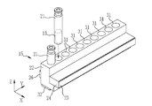
- the apparatus main body 11 includes a test body 21, a test body holding unit 22, a light emitting unit 23, a light guide unit 24, a light detection unit 26, a display unit 27, an operation unit 28, and the like.
- the test piece holding unit 22, the light emitting unit 23, the light guide unit 24, and the light detecting unit 26 constitute the measuring unit 15.
- the test body 21 is a container having a circular cross section for accommodating the inspection target 13.
- the state in which the inspection target is housed is also simply referred to as the test body 21.
- the circular cross section means that when at least the portion accommodating the inspection target 13 (particularly the portion irradiated with light for inspection) is horizontally cut in the state of being arranged in the device main body 11, the outer shape of the cross section is circular or elliptical. Or, it means that it has a generally smooth closed curve similar to this.
- the test body 21 is substantially cylindrical.
- the test body 21 is made of heat-resistant glass. This is to prevent the test piece 21 before containing the test object from containing endotoxin and (1 ⁇ 3) - ⁇ -D-glucan, for example, by dry heat sterilization at 250 ° C. or higher and 30 minutes or longer.
- the test body holding unit 22 holds a plurality of test bodies 21 side by side.
- the specimen holding portion 22 has a plurality of openings 31 arranged in a row (see FIG. 2). Therefore, by inserting the test body 21 into each opening 31, the test body holding unit 22 holds the plurality of test bodies 21 side by side in a row.
- the test body holding portion 22 has 10 openings 31, and by inserting the test body 21 into all of these, the test body 21 can be held at the same time. ..
- the test body holding unit 22 may hold 11 or more or 9 or less test bodies 21. Further, the test body holding portion 22 has a heater 32 on the bottom surface (the surface on the negative side in the Z direction).
- the test body holding unit 22 By controlling the on / off of the heater 32, the temperature of the test body holding unit 22 and the test body 21 held by the test body holding unit 22 can be maintained within a predetermined temperature or a predetermined temperature range. Therefore, the test body holding portion 22 also functions as a so-called constant temperature bath.
- the light emitting unit 23 irradiates the test body 21 held by the test body holding unit 22 with the light used for the inspection.
- the light emitting unit 23 includes a light emitting element 41.
- the light emitting element 41 is, for example, an LED (light emission diode), and by emitting light, the light 42 used for inspection is incident on the test body 21. Further, the light emitting element 41 emits light in a wide range capable of irradiating the light 42 toward at least two or more test bodies 21. Since the light emitting element 41 sends light 42 to a plurality of measurement sites (plurality of test bodies 21), a diffusion light source capable of obtaining substantially the same amount of light in each measurement site (each test body 21) in a certain direction. Is desirable.
- the light guide unit 24 guides the light 42 emitted by the light emitting element 41 to the test body 21 held by the test body holding unit 22.
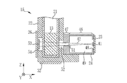
- the light guide unit 24 has a first light guide path 46 and a second light guide path 47 (see FIG. 3).
- the first light guide path 46 is a portion of the light guide portion 24 that is relatively located on the light emitting element 41 side, and has an opening 48 at the connection portion with the light emitting portion 23. Then, when the light emitting unit 23 is connected to the light guide unit 24, the light emitting element 41 is exposed to the first light guide path 46 through the opening 48. Therefore, the first light guide path 46 is a space that directly receives the light 42 generated by the light emitting element 41 and propagates it to the second light guide path 47. In the present embodiment, the first light guide path 46 is a space 49 filled with air and capable of being ventilated to the outside. However, a part or all of the space 49 may be filled with a dielectric material or the like, if necessary. The first light guide path 46 is for guiding the light 42 generated by the light emitting element 41 that emits light in a wide range toward at least two or more adjacent test bodies 21.
- the second light guide path 47 is formed to have a smaller diameter relative to the first light guide path 46, and guides the light 42 emitted by the light emitting element 41 from the first light guide path 46 to the test body 21.
- the second light guide path 47 is a portion of the light guide portion 24 that is relatively located on the test body holding portion 22 side, and has a through hole 51 at a connecting portion with the test body holding portion 22.
- the through hole 51 is a through hole parallel to the direction connecting the light emitting element 41 and the test body 21.
- the test body holding portion 22 is provided with an opening 52 at a position where at least the through hole 51 of the second light guide path 47 is exposed to the test body 21. Therefore, of the light 42 propagating in the space 49 of the first light guide path 46, the light 42 incident on the through hole 51 of the second light guide path 47 enters the test body 21 through the opening 52.
- the diameter is relatively small with respect to the first light guide path 46 means that the diameter of the through hole 51 (cross-sectional area in the YZ direction) of the second light guide path 47 at the connecting portion between the through hole 51 and the space 49 is defined as It means that it is smaller than the diameter (cross-sectional area in the YZ direction) of the space 49 of the first light guide path 46. Further, the through hole 51 of the second light guide path 47 is longer in the X direction than the effective diameter of the opening (the incident port of the light 42) on the space 49 side. That is, the through hole 51 has a substantial thickness in the XY in-plane direction, not just a surface.
- the second light guide path 47 limits the incident angle of the light 42 from the space 49 side to the through hole 51 and the emission angle of the light 42 from the through hole 51 to the test piece 21 side.
- the light 42 reflected or the like in the space 49 is incident on the through hole 51 at a wide angle, and such light 42 is emitted from the through hole 51 at a wide angle to be emitted from the test body 21. Prevents incident on.
- the second light guide path 47 suppresses the incident light from a light emitting element different from the light emitting element 41 that emits light in a wide range facing the second light guide path 47 from passing through the second light guide path 47, and the reflected light that can occur when the light passes through is tested.
- the generation of a false signal due to the incident on the body 21 is suppressed. That is, the second light guide path 47 limits the light 42 incident on the test body 21 to the light from only the opposing light emitting element 41, and further limits the light to substantially parallel light.
- the through hole 51 is provided at a position away from the light emitting element 41 via the space 49 also contributes to making the light 42 incident on the test body 21 substantially parallel light.
- the substantially parallel light means light that maintains parallelism to the extent that it passes directly through the through hole from the light emitting element.
- the photodetector 26 includes a light receiving element 53 that receives the light transmitted or scattered by the test body 21.
- the light receiving element 53 is, for example, an optical sensor such as a PD (PhotoDiode), and is provided for each test body 21.
- the photodetecting unit 26 is a light receiving element at a position where the light 42 transmitted through each of these test bodies 21 can be received. It has 53.
- the test body holding unit 22 is provided with an opening 54 between the test body 21 and the light receiving element 53 having a range in which at least the light receiving element 53 is exposed to the test body 21 side. Therefore, the light 42 that has passed through the test body 21 reaches the light receiving element 53 through the opening 54.
- the light emitting unit 23 includes a light emitting element 41, a light emitting element 62 that emits light having a wavelength band different from that of the light emitting element 41, and a light emitting element 63.
- the light emitting element 62 and the light emitting element 63 emit light in a wide range capable of irradiating light toward at least two or more test bodies 21.
- each measurement site is substantially equivalent to a certain direction. It is desirable that the light source is a diffused light source that can obtain the amount of light.
- the light emitting element 41, the light emitting element 62, and the light emitting element 63 each have a plurality of each, and the light emitting element 41, the light emitting element 62, and the light emitting element 63 are periodically arranged in this order along the X direction. There is.
- the light emitting element 41 is arranged substantially in front of each of the light receiving element 53 and the test body 21, and in the endotoxin inspection, the light emitting element 41 is the space 49 of the first light guide path 46 and the through hole 51 of the second light guide path 47.
- the test body 21 located in front of the light emitting element 41 is irradiated with the light 42.
- the light emitting element 41 is used, for example, when inspecting by a turbidimetry method, and the light 42 emitted by the light emitting element 41 is, for example, red.
- the front surface refers to a position on an extension of the normal of the light receiving surface of the light receiving element 53 passing through the center of the test body 21.
- the light emitted by the light emitting element 62 is, for example, purple. Further, the light emitted by the light emitting element 63 is, for example, blue.
- the light emitting element 62 and the light emitting element 63 are selected and used, for example, when inspecting by a colorimetric method. Further, in the arrangement of the plurality of light emitting elements, paying attention to the arrangement of the light emitting element 62 and the light emitting element 63, these are arranged alternately in the X direction.
- the measurement unit 15 has, as a light emitting element, a light emitting element 62 which is a first color light emitting element that emits light of a first color (for example, purple) and a second color (for example, blue) light different from the first color.
- the light emitting element 63 which is a second color light emitting element
- the light emitting element 63 which is a second color light emitting element
- the light emitting element 62 which is the first color light emitting element and the light emitting element 63 which is the second color light emitting element alternate.
- the light emitting element 41 is the third color light emitting element. That is, the measurement unit 15 has a third color different from the first color and the second color (for example, purple and blue) between the light emitting element 62 which is the first color light emitting element and the light emitting element 63 which is the second color light emitting element.
- Light of color for example, red
- the light emitting element 62 and the light emitting element 63 are arranged at positions other than the front of the light receiving element 53 and the test body 21 (between the two light emitting elements 41 (particularly the intermediate point)). Further, when the light emitting element 62 and the light emitting element 63 emit light, the light is simultaneously incident on two adjacent test bodies 21 among the plurality of test bodies 21 held by the test body holding unit 22. Therefore, the light emitting element 62 and the light emitting element 63 incident light from an oblique direction with respect to the direction connecting the light receiving element 53 and the test body 21.
- the first light guide path 46 is commonly provided in a plurality of light emitting elements (a plurality of light emitting elements 41, a light emitting element 62, and a light emitting element 63, each of which is present in a plurality of light emitting elements). That is, the space 49 forming the first light guide path 46 is not divided into each test body 21 or the like, and is a continuous region in the X direction. Therefore, the first light guide path 46 does not hinder the propagation of the light emitted by any of the light emitting element 41, the light emitting element 62, and the light emitting element 63, each of which has a plurality of light emitting elements 41.
- the through hole 72L and the through hole 72R that guide the light emitted by the light emitting element 62 and the light emitting element 63. A through hole 73L, and a through hole 73R.
- the through hole 72L and the through hole 72R are through holes parallel to the direction connecting the light emitting element 62 and the test body 21. Therefore, the through hole 72L guides the light emitted by the light emitting element 62 to the test body 21 on the left side (negative side in the X direction) when viewed from the light emitting element 62. The through hole 72R guides the light emitted by the light emitting element 62 to the test body 21 on the right side (positive side in the X direction) when viewed from the light emitting element 62.
- the through hole 73L and the through hole 73R are through holes substantially parallel to the direction connecting the light emitting element 63 and the test body 21. Therefore, the through hole 73L guides the light emitted by the light emitting element 63 to the test body 21 on the left side (negative side in the X direction) when viewed from the light emitting element 63. The through hole 73R guides the light emitted by the light emitting element 63 to the test body 21 on the right side (positive side in the X direction) when viewed from the light emitting element 63.
- the through hole 72L, the through hole 72R, the through hole 73L, and the through hole 73R have the diameters of the through hole 72L, the through hole 72R, the through hole 73L, and the through hole 73R (in the YZ direction) at the connection portion with the space 49.
- the cross-sectional area) is smaller than the diameter of the first light guide path 46 (cross-sectional area in the YZ direction). Therefore, with respect to the through hole 72L, the through hole 72R, the through hole 73L, and the through hole 73R, the second light guide path 47 is formed to have a smaller diameter relative to the first light guide path 46, and the first light guide path 47 is formed.
- the light emitted by the light emitting element 62 and the light emitting element 63 is guided from the 46 to the test body 21.
- the opening 52 of the test body holding portion 22 exposes the through hole 72L, the through hole 72R, the through hole 73L, and the through hole 73R to the test body 21.
- the opening 54 of the test body holding portion 22 does not prevent the light incident on the test body 21 from reaching the light receiving element 53 through the through hole 72L, the through hole 72R, the through hole 73L, and the through hole 73R.
- the through hole 72L, the through hole 72R, the through hole 73L, and the through hole 73R are longer in the extending direction than the effective diameter of the opening (light incident port) on the space 49 side, and these are not merely surfaces but substantially. Thickness. Therefore, in the second light guide path 47, the light reflected or the like in the space 49 is incident on the through hole 72L, the through hole 72R, the through hole 73L, and the through hole 73R at a wide angle, and such light penetrates at a wide angle. It prevents the light from coming out of the hole 72L, the through hole 72R, the through hole 73L, and the through hole 73R and entering the test body 21.
- the second light guide path 47 limits the light incident on the test body 21 to substantially parallel light even when the light emitting element 62 and the light emitting element 63 are used. Further, the light incident on the test piece is also that the through hole 72L, the through hole 72R, the through hole 73L, and the through hole 73R are provided at positions separated from the light emitting element 62 and the light emitting element 63 via the space 49. It contributes to making 42 almost parallel light.
- the display unit 27 is, for example, an indicator indicating whether or not the inspection can be executed and / or the progress of the inspection. Further, the display unit 27 can be a display screen such as a liquid crystal panel, a touch panel, or the like.
- the operation unit 28 is a switch or the like for directly giving an operation instruction to the device main body 11.
- the display unit 27 is a touch panel
- at least a part of the operation unit 28 can be formed by using a graphical user interface to be displayed on the touch panel.
- the computer 12 is a part of the inspection device 10 that controls each part of the device main body 11 and performs analysis or determination using measurement data (signals and the like acquired from the light receiving element 53) acquired from the device main body 11. Specifically, the computer 12 acquires measurement data from the measurement unit 15 and analyzes or the like using the measurement data to generate data capable of determining the presence or absence of endotoxin or determining the presence or absence of endotoxin. In the present embodiment, the computer 12 is provided separately from the device main body 11, but a part or all of the functions of the computer 12 can be incorporated into the device main body 11.
- the inspection device 10 can perform endotoxin inspection by the colorimetric method and the turbidity method.
- the colorimetric method is a test method for identifying the presence or absence of endotoxin by measuring the activation of the lysate reagent by endotoxin by the absorbance at a specific wavelength. Since the measurement unit 15 includes two types of light emitting elements, that is, a light emitting element 62 and a light emitting element 63 for inspection by the colorimetric method, the light emitting element 62 or the light emitting element 63 can be adjusted according to the characteristics of the inspection target 13 and the like. Perform an endotoxin test using either.
- the turbidimetry method is an inspection method for identifying the presence or absence of endotoxin by measuring the change in turbidity of a sample gelled by activation of a lysate reagent by endotoxin.
- the light emitting element 41 for each test piece 21 is used.
- the inspection device 10 includes three types of light emitting elements, that is, a light emitting element 41, a light emitting element 62, and a light emitting element 63, for endotoxin inspection by the turbidimetric method and the colorimetric method.
- the light emitting element 62 and the light emitting element 63 are arranged between two adjacent test bodies 21, and the light is incident on both the one light emitting element 62 or the light emitting element 63 and the two adjacent test bodies 21. ..
- the length in the X direction can be shortened for one test piece 21 as compared with the case where the light emitting element 41, the light emitting element 62, and the light emitting element 63 are provided one by one, and the inspection device 10 as a whole can be formed. Can be miniaturized. Further, as in the first embodiment, even if the light emitting element 41 for the turbidimetry method is added to each test body 21, its small size can be maintained.
- test body 21 is made of glass to withstand the dry heat sterilization process and has a circular cross section, when light is incident on the test body 21 from an oblique direction, the light is reflected or the like on the surface of the test body 21. It becomes difficult for light to enter the inspection target 13, and as a result, the inspection accuracy may decrease. For example, when the light used for inspection is guided by an optical fiber or the like, or when the light is focused on the test body 21 through a diaphragm having substantially no thickness, the position of the test body 21 is slight.
- the inspection device 10 When the amount of light expected to be incident on the test body 21 and the inspection target 13 is different from the amount of light actually incident on the test body 21 and the inspection target 13 due to misalignment or the like, and as a result, the inspection accuracy is lowered. There is. However, in the inspection device 10, the light emitting element 62 or the light emitting element 63 is emitted to both of the two adjacent test bodies 21 by guiding the light to the test body 21 by the first light guide path 46 and the second light guide path 47. While allowing light to enter, the light incident on the test body 21 is narrowed down by a through hole (through hole 72L or the like) and is arranged to be substantially parallel light.
- a through hole through hole 72L or the like
- the inspection device 10 holds the plurality of test bodies 21 and can accurately perform the endotoxin test by the plurality of inspection methods while forming the test body 21 in a small size.
- the inspection device 10 contains a fat component because the light incident on the test body 21 is finely narrowed by a through hole (through hole 72L or the like) and is arranged to be substantially parallel light. Due to the characteristics of the inspection target 13, even if the inspection target 13 is turbid from the beginning (before the reaction between the endotoxin and the lysate reagent), the light of the planned amount of light is likely to be incident on the inspection target 13. Therefore, the inspection device 10 can perform the endotoxin inspection with high accuracy.
- the first light guide path 46 that is, the inner surface forming the space 49 and the portion of the light emitting unit 23 other than the light emitting element 41
- the second light guide path 47 at least the second light guide path. It is desirable that the surface (inner surface portion) forming 47) has as low reflection as possible. Therefore, it is preferable to form the first light guide path 46 and the second light guide path 47 by using a light absorbing material, a surface coating, or the like. Therefore, the first light guide path 46 and the second light guide path 47 can be subjected to, for example, a matte black alumite treatment or a black paint can be applied.
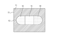
- the light receiving element 53 mounted on the inspection device 10 of the first embodiment is provided with a shielding member 81 for limiting the incident light on the light receiving surface thereof, and the opening 82 of the shielding member 81 is provided. It is preferable that the test body 21 receives the transmitted or scattered light through the light. This is to limit the reception of unintended stray light and scattered light and improve the inspection accuracy. Further, the opening 82 provided in the shielding member 81 may be formed to the minimum according to the position, size, and shape of the spot of light incident on the test body 21 by the light emitting element 41, the light emitting element 62, and the light emitting element 63. preferable. For example, as shown in FIG.
- a so-called stadium-type opening 82 is formed, and the spot 86 reached by the light 42 emitted by the light emitting element 41, the spot 87 reached by the light emitted by the light emitting element 62, and the light emitting element 63 emit light.
- the shape is long in the arrangement direction (X direction) of the light emitting element 41, the light emitting element 62, and the light emitting element 63 so as to include the spot 88 to which the light is reached to almost the minimum. In this case, it is possible to limit the reception of unnecessary light with higher accuracy and further improve the inspection accuracy.
- the shape long in the arrangement direction of the light emitting elements includes an ellipse or a rectangle having a long axis in the arrangement direction of the light emitting elements.
- the opening 82 is provided with a color filter that selectively transmits the light emitted by the light emitting element.
- the opening 82 is divided into a plurality of regions according to the position, size, and shape of the light spot in which the light emitting element 41, the light emitting element 62, and the light emitting element 63 are incident on the test body 21, and each region is divided into a plurality of regions. It is preferable to provide color filters having different colors of transmitted light. Specifically, as shown in FIG.
- the light emitting element 41 the light emitting element 62, and the color filters 91 to 93 that selectively transmit the light emitted by the light emitting element 63.
- the color filter 91 selectively transmits the light 42 emitted by the light emitting element 41.
- the color filter 92 selectively transmits the light emitted by the light emitting element 62 (for example, purple light).
- the color filter 93 selectively transmits the light (for example, blue light) emitted by the light emitting element 63.
- the size of the opening 82 is substantially limited to a certain portion of the color filter 91, so that it becomes difficult to receive the scattered light that reaches the positions of the color filter 92 and the color filter 93. is there.
- the light emitting element 62 or the light emitting element 63 is used.
- color filters 91 to 93 can be provided in the opening 82 even when the opening 82 has a shape long in the arrangement direction of the stadium type or other light emitting elements.
- the outer size of the opening 82 is originally narrowed down to a small size, and the effective opening size is optimized by the color filters 91 to 93, so that the inspection can be performed with particularly high accuracy.
- the color filters 91 to 93 are used in the opening 82 of the shielding member 81, but the color filters 91 to 93 are extended to the end of the light receiving surface of the light receiving element 53 to shield the color filters 91 to 93.
- the member 81 can be omitted.
- the above modification is an example in which one light receiving element 53 is provided per test body 21, but the number of light receiving elements 53 is increased and the number of incident wavelengths (type of light emitting element) is increased per test body 21. Two or three light receiving elements may be provided. In this case, the measuring accuracy can be further improved by appropriately providing a shielding member 81 toward each light receiving element and providing color filters 91 to 93.
- the second light guide path 47 having a substantial thickness in the XY in-plane direction is formed by providing a through hole 51 or the like in one plate-shaped member.
- the second light guide path 47 can be formed in another form.
- the second light guide path 47 has a configuration in which a plurality of plates having through holes (hereinafter referred to as through hole plates) are arranged so that light penetrates in parallel with the direction connecting the light emitting element 41 and the like and the test body 21. can do.
- a partition member 201 for partitioning the first light guide path 46 and the test body holding portion 22 is provided, and the partition member 201 emits light in front of each test body 21.
- An opening 202 is provided for passing the light emitted by the element 41, the light emitting element 62, and the light emitting element 63 toward the test body 21 side.
- the opening 202 is provided with a first through-hole plate 203 and a second through-hole plate 204, respectively, before and after (for example, the opening end on the side of the light emitting element 41 and the like and the opening end on the test body 21 side).
- the first through hole plate 203 is provided on the front end side (the side of the light emitting element 41 or the like) of the opening 202, and has a first through hole 211, a second through hole 212, and a third through hole 213.
- the first through hole 211 is on a straight line connecting the light emitting element 41 and the test body 21
- the second through hole 212 is on the straight line connecting the light emitting element 62 and the test body 21
- the third through hole 213 is the light emitting element. It is on a straight line connecting 63 and the test body 21.
- the second through hole plate 204 is provided on the rear end side (the side of the test body 21) of the opening 202, and has a first through hole 221 and a second through hole 222, and a third through hole 223.
- the first through hole 221 is on a straight line connecting the light emitting element 41 and the test body 21
- the second through hole 222 is on the straight line connecting the light emitting element 62 and the test body 21
- the third through hole 223 is a light emitting element. It is on a straight line connecting 63 and the test body 21.
- the first through hole 211 and the second through hole plate 204 of the first through hole plate 203 The first through hole 221 functions substantially in the same manner as the through hole 51 of the first embodiment. That is, the first through hole 211 of the first through hole plate 203 and the first through hole 221 of the second through hole plate 204 have the incident angle of the light 42 emitted by the light emitting element 41 and the light 42 toward the test body 21 side. Limit the emission angle of.
- the space between the first through hole 211 of the first through hole plate 203 and the first through hole 221 of the second through hole plate 204 is hollow.
- the test body 21 Only the light 42 passing through the space accurately and substantially straight reaches the test body 21.
- the light reflected by the inner wall of the through hole 51 may generate a false signal, although it is very small.
- the incident angle of the light 42 emitted by the light emitting element 41 and the side of the test body 21 The emission angle of the light 42 can be limited more accurately, and the generation of false signals can be suppressed more reliably.
- the second through hole 212 of the first through hole plate 203 and the second through hole plate 204 are formed.
- the through hole 222 functions substantially in the same manner as the through hole 72L (or through hole 72R) of the first embodiment, and the incident angle of the light emitted by the light emitting element 62 and the emission angle of the light to the test piece 21 side. To limit. The restrictions on the incident angle and the emission accuracy are more accurate than those of the through hole 72L (or through hole 72R) of the first embodiment, and the generation of false signals can be suppressed more reliably.
- the third through-hole 213 and the second through-hole plate 204 of the first through-hole plate 203 are formed.
- the three through holes 223 function substantially in the same manner as the through holes 73R (or through holes 73R) of the first embodiment, and the incident angle of the light emitted by the light emitting element 63 and the emission of the light to the test piece 21 side. Limit the angle. The restrictions on the incident angle and the emission accuracy are more accurate than those of the through hole 73R (or through hole 73R) of the first embodiment, and the generation of false signals can be suppressed more reliably.
- the second light guide path 47 is formed by using two through hole plates, the first through hole plate 203 and the second through hole plate 204, but the second light guide path 47 is formed. , By arranging a through hole plate similar to these between the first through hole plate 203 and the second through hole plate 204, it may be formed by using three or more through hole plates.
- the through-hole plate similar to the first through-hole plate 203 and the second through-hole plate 204 described above is exposed to the test piece 21 side of the light receiving element 53. It can be provided in or at the end of the opening 54 having a range to be used.
- the third through hole plate 261 has a first through hole 271, a second through hole 272, and a third through hole 273.
- the first through hole 271 is on a straight line connecting the light emitting element 41 and the test body 21
- the second through hole 272 is on the straight line connecting the light emitting element 62 and the test body 21
- the third through hole 273 is a light emitting element. It is on a straight line connecting 63 and the test body 21.
- the third through-hole plate 261 is provided in the opening 54 provided on the front surface of the light receiving element 53, the light scattered by the test body 21 and / or the inspection target 13 or the like reaches the light receiving element 53. It can be prevented and the generation of false signals can be suppressed more reliably.
- the first through hole plate 203 is formed with the first through hole 211, the second through hole 212, and the third through hole 213 along the traveling direction of light, and the second through hole 212 and The third through hole 213 is obliquely opened with respect to the first through hole plate 203.
- the first through hole 211, the second through hole 212, and the third through hole 213 (particularly the second through hole 212 and the third through hole 213) of the first through hole plate 203 are the first through hole plate 203.
- the first through-hole plate 203 is preferably a thin plate within a range that does not interfere with measurement, strength, or the like.
- the first through-hole plate 203, the second through-hole plate 204, and the third through-hole plate 261 are provided independently for each test piece 21, but these are a plurality of each. It may be provided in common with the test body 21. That is, the plurality of first through-hole plates 203 can be integrally formed. The same applies to the second through-hole plate 204 and the third through-hole plate 261.
- the second embodiment can be arbitrarily combined with the modifications of the first embodiment and the first embodiment for configurations other than the second light guide path 47.
- the inspection device 10 performs endotoxin inspection by the turbidimetry method and the colorimetric method, but only the inspection by the turbidimetry method. Can omit the configuration (light emitting element 62, light emitting element 63, etc.) related to the inspection by the colorimetric method. Similarly, when the inspection device 10 only performs the inspection by the colorimetric method, the configuration (light emitting element 41, through hole 51, etc.) related to the inspection by the turbidimetry method can be omitted.
- the inspection device 10 when the inspection by the colorimetric method is performed with only one specific wavelength (for example, purple light or blue light), the inspection device 10 includes the light emitting element 62 and related configurations (through hole 72L, through hole 72R, etc.). , Or any of the light emitting element 63 and related configurations (through hole 73L, through hole 73R, etc.) can be omitted.
- the light emitting element 62 and the light emitting element 63 are arranged at the midpoint between the two light emitting elements 41. This is to allow light to be optically symmetrically incident on two adjacent test pieces 21. The inspection accuracy can be improved by injecting light optically symmetrically on two adjacent test pieces 21. It is particularly effective when performing calculations to determine the presence or absence of endotoxin.
- the inspection device 10 performs an endotoxin test
- the present invention is a device that performs a test other than the endotoxin test for detecting transmitted light, scattered light, or the like. Can be used for.
- the inspection device 10 includes one measurement unit 15, but the inspection device 10 includes a plurality of measurement units 15 in the device main body 11. Is also good. That is, the inspection device 10 includes a test body 21 having a circular cross section for accommodating the inspection target 13, a test body holding portion 22 for holding a plurality of test bodies 21 in a row, and two adjacent test bodies 21 among the plurality of test bodies 21.
- the light emitting elements 62 and 63 that incident light on the test body 21, the first light guide path 46 that guides the light emitted by the light emitting element, and the first light guide path that is formed to have a smaller diameter than the first light guide path 46.
- the test body 21 may be provided with a plurality of measurement units 15 having a second light guide path 47 for guiding the light emitted by the light emitting elements 62 and 63 from the 46 to the test body 21.
Landscapes
- Health & Medical Sciences (AREA)
- Life Sciences & Earth Sciences (AREA)
- Chemical & Material Sciences (AREA)
- Engineering & Computer Science (AREA)
- Immunology (AREA)
- Physics & Mathematics (AREA)
- Analytical Chemistry (AREA)
- Biochemistry (AREA)
- General Health & Medical Sciences (AREA)
- General Physics & Mathematics (AREA)
- Pathology (AREA)
- Biomedical Technology (AREA)
- Molecular Biology (AREA)
- Hematology (AREA)
- Urology & Nephrology (AREA)
- Biotechnology (AREA)
- Microbiology (AREA)
- Bioinformatics & Cheminformatics (AREA)
- Medicinal Chemistry (AREA)
- Wood Science & Technology (AREA)
- Organic Chemistry (AREA)
- Zoology (AREA)
- Cell Biology (AREA)
- Food Science & Technology (AREA)
- Chemical Kinetics & Catalysis (AREA)
- Plasma & Fusion (AREA)
- Sustainable Development (AREA)
- General Engineering & Computer Science (AREA)
- Genetics & Genomics (AREA)
- Computer Hardware Design (AREA)
- Spectroscopy & Molecular Physics (AREA)
- Investigating Or Analysing Materials By Optical Means (AREA)
- Measuring Or Testing Involving Enzymes Or Micro-Organisms (AREA)
- Investigating Or Analysing Materials By The Use Of Chemical Reactions (AREA)
- Apparatus Associated With Microorganisms And Enzymes (AREA)
- Measurement Of The Respiration, Hearing Ability, Form, And Blood Characteristics Of Living Organisms (AREA)
Priority Applications (5)
| Application Number | Priority Date | Filing Date | Title |
|---|---|---|---|
| CN202080074995.XA CN114599979B (zh) | 2019-11-19 | 2020-10-14 | 检查装置 |
| JP2021558220A JP7340034B2 (ja) | 2019-11-19 | 2020-10-14 | 検査装置 |
| ES20889859T ES2987707T3 (es) | 2019-11-19 | 2020-10-14 | Dispositivo de inspección |
| EP20889859.3A EP4063480B1 (en) | 2019-11-19 | 2020-10-14 | Inspection device |
| US17/720,774 US12111314B2 (en) | 2019-11-19 | 2022-04-14 | Test device |
Applications Claiming Priority (2)
| Application Number | Priority Date | Filing Date | Title |
|---|---|---|---|
| JP2019-208890 | 2019-11-19 | ||
| JP2019208890 | 2019-11-19 |
Related Child Applications (1)
| Application Number | Title | Priority Date | Filing Date |
|---|---|---|---|
| US17/720,774 Continuation US12111314B2 (en) | 2019-11-19 | 2022-04-14 | Test device |
Publications (1)
| Publication Number | Publication Date |
|---|---|
| WO2021100367A1 true WO2021100367A1 (ja) | 2021-05-27 |
Family
ID=75980604
Family Applications (1)
| Application Number | Title | Priority Date | Filing Date |
|---|---|---|---|
| PCT/JP2020/038808 Ceased WO2021100367A1 (ja) | 2019-11-19 | 2020-10-14 | 検査装置 |
Country Status (6)
| Country | Link |
|---|---|
| US (1) | US12111314B2 (https=) |
| EP (1) | EP4063480B1 (https=) |
| JP (1) | JP7340034B2 (https=) |
| CN (1) | CN114599979B (https=) |
| ES (1) | ES2987707T3 (https=) |
| WO (1) | WO2021100367A1 (https=) |
Cited By (1)
| Publication number | Priority date | Publication date | Assignee | Title |
|---|---|---|---|---|
| WO2024262213A1 (ja) * | 2023-06-20 | 2024-12-26 | 株式会社ジャパンディスプレイ | 検出装置 |
Citations (7)
| Publication number | Priority date | Publication date | Assignee | Title |
|---|---|---|---|---|
| JPH09159671A (ja) | 1995-10-05 | 1997-06-20 | Wako Pure Chem Ind Ltd | 微生物由来成分の測定装置及び測定方法 |
| JP2011002379A (ja) | 2009-06-19 | 2011-01-06 | Kowa Co | 光学的反応測定装置および光学的反応測定方法 |
| JP2012154815A (ja) * | 2011-01-26 | 2012-08-16 | Iwate Medical Univ | 生物由来の生理活性物質の測定方法及び測定装置 |
| JP2013528359A (ja) * | 2010-04-06 | 2013-07-11 | アイティ−アイエス インターナショナル リミテッド | 生化学反応システム |
| JP2014215298A (ja) | 2013-04-29 | 2014-11-17 | ポール・コーポレーションPallCorporation | エンドトキシンの検出及び/又は定量 |
| JP2018009953A (ja) * | 2016-06-30 | 2018-01-18 | シスメックス株式会社 | 測定装置および測定方法 |
| US20190113514A1 (en) * | 2017-10-17 | 2019-04-18 | Board Of Regents, The University Of Texas System | Limulus amoebocyte lysate assay and method of same |
Family Cites Families (8)
| Publication number | Priority date | Publication date | Assignee | Title |
|---|---|---|---|---|
| US5073029A (en) * | 1990-02-16 | 1991-12-17 | Eqm Research, Inc. | Multisource device for photometric analysis and associated chromogens |
| FI86340C (fi) * | 1990-10-31 | 1992-08-10 | Labsystems Oy | Foerfarande foer ledning av ljus. |
| US8507282B2 (en) * | 2009-03-13 | 2013-08-13 | Kowa Company, Ltd. | Method for measuring physiologically active substance of biological origin, program for implementing the same, and apparatus for measuring physiologically active substance of biological origin |
| US20130309704A1 (en) * | 2011-01-26 | 2013-11-21 | Kowa Company, Ltd. | Method and apparatus for measuring physiologically active substance derived from organism |
| TW201723482A (zh) * | 2015-08-18 | 2017-07-01 | 新加坡科技研究局 | 光學結構及光學光偵測系統 |
| JP6581483B2 (ja) * | 2015-11-27 | 2019-09-25 | シスメックス株式会社 | 検体分析装置 |
| CN107561298B (zh) | 2016-06-30 | 2020-05-05 | 希森美康株式会社 | 测定装置以及测定方法 |
| DE102018111033A1 (de) | 2018-05-08 | 2019-11-14 | Byonoy Gmbh | Transmissionsvorrichtung zur Untersuchung von Proben in Kavitäten einer Mikrotiterplatte und Verfahren zum Untersuchen von Proben in Kavitäten einer Mikrotiterplatte mittels Transmission |
-
2020
- 2020-10-14 ES ES20889859T patent/ES2987707T3/es active Active
- 2020-10-14 EP EP20889859.3A patent/EP4063480B1/en active Active
- 2020-10-14 WO PCT/JP2020/038808 patent/WO2021100367A1/ja not_active Ceased
- 2020-10-14 JP JP2021558220A patent/JP7340034B2/ja active Active
- 2020-10-14 CN CN202080074995.XA patent/CN114599979B/zh active Active
-
2022
- 2022-04-14 US US17/720,774 patent/US12111314B2/en active Active
Patent Citations (7)
| Publication number | Priority date | Publication date | Assignee | Title |
|---|---|---|---|---|
| JPH09159671A (ja) | 1995-10-05 | 1997-06-20 | Wako Pure Chem Ind Ltd | 微生物由来成分の測定装置及び測定方法 |
| JP2011002379A (ja) | 2009-06-19 | 2011-01-06 | Kowa Co | 光学的反応測定装置および光学的反応測定方法 |
| JP2013528359A (ja) * | 2010-04-06 | 2013-07-11 | アイティ−アイエス インターナショナル リミテッド | 生化学反応システム |
| JP2012154815A (ja) * | 2011-01-26 | 2012-08-16 | Iwate Medical Univ | 生物由来の生理活性物質の測定方法及び測定装置 |
| JP2014215298A (ja) | 2013-04-29 | 2014-11-17 | ポール・コーポレーションPallCorporation | エンドトキシンの検出及び/又は定量 |
| JP2018009953A (ja) * | 2016-06-30 | 2018-01-18 | シスメックス株式会社 | 測定装置および測定方法 |
| US20190113514A1 (en) * | 2017-10-17 | 2019-04-18 | Board Of Regents, The University Of Texas System | Limulus amoebocyte lysate assay and method of same |
Cited By (1)
| Publication number | Priority date | Publication date | Assignee | Title |
|---|---|---|---|---|
| WO2024262213A1 (ja) * | 2023-06-20 | 2024-12-26 | 株式会社ジャパンディスプレイ | 検出装置 |
Also Published As
| Publication number | Publication date |
|---|---|
| CN114599979A (zh) | 2022-06-07 |
| EP4063480A1 (en) | 2022-09-28 |
| CN114599979B (zh) | 2025-06-10 |
| JP7340034B2 (ja) | 2023-09-06 |
| EP4063480A4 (en) | 2023-01-11 |
| JPWO2021100367A1 (https=) | 2021-05-27 |
| US12111314B2 (en) | 2024-10-08 |
| US20220236263A1 (en) | 2022-07-28 |
| EP4063480B1 (en) | 2024-07-10 |
| ES2987707T3 (es) | 2024-11-15 |
Similar Documents
| Publication | Publication Date | Title |
|---|---|---|
| CN105308437B (zh) | 进行样本的冷光和荧光测量的装置和相关方法 | |
| CA2448390C (en) | Semen analysis | |
| JP2007501415A (ja) | プロセス監視用の装置及び方法 | |
| JPH10153597A (ja) | 血清変数の存在を決定する方法 | |
| JP2017151436A (ja) | 微小ウェルの分析のための光学機器 | |
| JP7206570B2 (ja) | 分析装置 | |
| CN114563329B (zh) | 光学检测装置及细胞分析仪 | |
| US8155487B2 (en) | Sensor element | |
| US12111314B2 (en) | Test device | |
| CN113196039A (zh) | 样本光学检测装置、样本检测方法及样本分析仪 | |
| CN113588520A (zh) | 光学检测装置及细胞分析仪 | |
| CN113008786A (zh) | 血液细胞分析仪 | |
| CN214584775U (zh) | 光学检测装置及细胞分析仪 | |
| US20040110305A1 (en) | Method of mixing a sample with a reagent in a chemistry | |
| EP1064095A1 (en) | Method and apparatus for measuring proteins | |
| JP7539977B2 (ja) | 検査装置 | |
| US20020110487A1 (en) | Apparatus and method for handling fluids | |
| US9791377B2 (en) | Optochemical sensor | |
| CN217304824U (zh) | 一种样本分析仪及粒子测定装置 | |
| CN115575188A (zh) | 一种血液分析仪 | |
| WO2013150910A1 (ja) | 計数チップ、計数方法、および計数装置 | |
| JP2015121458A (ja) | 複合型ゲル粒子検出器およびその動作方法並びにエンドトキシン濃度の測定方法 | |
| WO2011016775A1 (en) | A sensor element | |
| WO2015122749A1 (ko) | 체액 분석 장치 및 이를 이용하는 체액 분석 방법 | |
| JP2006308412A (ja) | 蛍光共鳴検出装置 |
Legal Events
| Date | Code | Title | Description |
|---|---|---|---|
| 121 | Ep: the epo has been informed by wipo that ep was designated in this application |
Ref document number: 20889859 Country of ref document: EP Kind code of ref document: A1 |
|
| ENP | Entry into the national phase |
Ref document number: 2021558220 Country of ref document: JP Kind code of ref document: A |
|
| NENP | Non-entry into the national phase |
Ref country code: DE |
|
| ENP | Entry into the national phase |
Ref document number: 2020889859 Country of ref document: EP Effective date: 20220620 |
|
| WWG | Wipo information: grant in national office |
Ref document number: 202080074995.X Country of ref document: CN |