WO2021100324A1 - 情報処理装置 - Google Patents
情報処理装置 Download PDFInfo
- Publication number
- WO2021100324A1 WO2021100324A1 PCT/JP2020/036905 JP2020036905W WO2021100324A1 WO 2021100324 A1 WO2021100324 A1 WO 2021100324A1 JP 2020036905 W JP2020036905 W JP 2020036905W WO 2021100324 A1 WO2021100324 A1 WO 2021100324A1
- Authority
- WO
- WIPO (PCT)
- Prior art keywords
- control
- information processing
- operation device
- response
- setting request
- Prior art date
- Legal status (The legal status is an assumption and is not a legal conclusion. Google has not performed a legal analysis and makes no representation as to the accuracy of the status listed.)
- Ceased
Links
Images



Classifications
-
- G—PHYSICS
- G06—COMPUTING OR CALCULATING; COUNTING
- G06F—ELECTRIC DIGITAL DATA PROCESSING
- G06F9/00—Arrangements for program control, e.g. control units
- G06F9/06—Arrangements for program control, e.g. control units using stored programs, i.e. using an internal store of processing equipment to receive or retain programs
- G06F9/46—Multiprogramming arrangements
- G06F9/48—Program initiating; Program switching, e.g. by interrupt
- G06F9/4806—Task transfer initiation or dispatching
- G06F9/4843—Task transfer initiation or dispatching by program, e.g. task dispatcher, supervisor, operating system
- G06F9/4881—Scheduling strategies for dispatcher, e.g. round robin, multi-level priority queues
-
- G—PHYSICS
- G06—COMPUTING OR CALCULATING; COUNTING
- G06F—ELECTRIC DIGITAL DATA PROCESSING
- G06F3/00—Input arrangements for transferring data to be processed into a form capable of being handled by the computer; Output arrangements for transferring data from processing unit to output unit, e.g. interface arrangements
- G06F3/01—Input arrangements or combined input and output arrangements for interaction between user and computer
- G06F3/016—Input arrangements with force or tactile feedback as computer generated output to the user
-
- A—HUMAN NECESSITIES
- A63—SPORTS; GAMES; AMUSEMENTS
- A63F—CARD, BOARD, OR ROULETTE GAMES; INDOOR GAMES USING SMALL MOVING PLAYING BODIES; VIDEO GAMES; GAMES NOT OTHERWISE PROVIDED FOR
- A63F13/00—Video games, i.e. games using an electronically generated display having two or more dimensions
- A63F13/25—Output arrangements for video game devices
- A63F13/28—Output arrangements for video game devices responding to control signals received from the game device for affecting ambient conditions, e.g. for vibrating players' seats, activating scent dispensers or affecting temperature or light
- A63F13/285—Generating tactile feedback signals via the game input device, e.g. force feedback
-
- A—HUMAN NECESSITIES
- A63—SPORTS; GAMES; AMUSEMENTS
- A63F—CARD, BOARD, OR ROULETTE GAMES; INDOOR GAMES USING SMALL MOVING PLAYING BODIES; VIDEO GAMES; GAMES NOT OTHERWISE PROVIDED FOR
- A63F2300/00—Features of games using an electronically generated display having two or more dimensions, e.g. on a television screen, showing representations related to the game
- A63F2300/20—Features of games using an electronically generated display having two or more dimensions, e.g. on a television screen, showing representations related to the game characterised by details of the game platform
- A63F2300/209—Features of games using an electronically generated display having two or more dimensions, e.g. on a television screen, showing representations related to the game characterised by details of the game platform characterized by low level software layer, relating to hardware management, e.g. Operating System, Application Programming Interface
Definitions
- the present invention relates to an information processing device that executes processing according to operation information received by an operation device, a control method thereof, and a program.
- the information processing device may cause the connected operation device to execute various controls such as operation feedback and generation of vibration.
- Each process executed by the information processing device requests the operation device to execute such control, so that the operation device executes an operation according to the content of the process executed by itself.
- the present invention has been made in consideration of the above circumstances, and one of the objects thereof is to provide an information processing device, a control method thereof, and a program capable of avoiding conflict of control demands with respect to an operating device. It is in.
- the information processing device is an information processing device connected to an operation device, and the operation device is connected to a process execution unit that executes a plurality of processes in parallel and the operation device.
- the operation device control unit includes an operation device control unit that transmits a control command instructing the content of control processing to be executed, and the operation device control unit is a selection process selected from the plurality of processes according to a given condition.
- the control command is transmitted in response to the setting request received from, and the transmission of the control command in response to the setting request received from a process other than the selection process is restricted.
- the control method of the information processing device is a control method of the information processing device connected to the operation device, wherein a step of executing a plurality of processes in parallel and the operation device
- the control step includes a control step for transmitting a control command instructing the content of the control process to be executed by the operation device, and the control step is a selection process selected from the plurality of processes according to a given condition.
- the control command is transmitted in response to the setting request received from, and the transmission of the control command in response to the setting request received from a process other than the selection process is restricted.
- the program according to one aspect of the present invention describes a step of executing a plurality of processes in parallel on a computer connected to an operation device, and a content of control processing to be executed by the operation device on the operation device.
- the control command is transmitted in response to the above control command, and the transmission of the control command in response to a setting request received from a process other than the selection process is restricted.
- the program may be provided stored in a computer-readable, non-temporary information storage medium.
- FIG. 1 is an overall configuration diagram of the information processing system 1 according to the embodiment of the present invention.
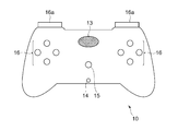
- FIG. 2 is a diagram showing an example of the appearance of the operation device 10.
- the information processing system 1 includes an operation device 10 and an information processing device 50.
- the operation device 10 and the information processing device 50 transmit and receive data by wireless communication such as a Bluetooth (registered trademark) standard.
- wireless communication such as a Bluetooth (registered trademark) standard.
- data is transmitted and received by wireless communication, but the present invention is not limited to this, and the operation device 10 and the information processing device 50 may be connected by wire according to a standard such as USB.
- the operation device 10 is, for example, a controller for a home-use game machine, and includes a control circuit 11, an audio signal processing circuit 12, a speaker 13, a headphone terminal 14, a microphone 15, a plurality of operation members 16, and the like. It is configured to include a vibration mechanism 17 and a force sense presentation mechanism 18.
- the control circuit 11 is a microprocessor or the like, and executes a process for controlling each part of the operation device 10. Specifically, the control circuit 11 outputs a control signal for operating the vibration mechanism 17, the force sense presentation mechanism 18, and the like according to the control command received from the information processing device 50. Further, the state of each operation member 16 is periodically scanned to identify the operation content performed by the user, and the operation information indicating the operation content is transmitted to the information processing device 50.
- control circuit 11 receives the reproduction audio signal from the information processing device 50, and transmits the reproduction audio signal to the audio signal processing circuit 12. Further, the control circuit 11 receives the sound collecting voice signal from the voice signal processing circuit 12, and transmits the sound collecting voice signal to the information processing device 50. In order to send and receive such various audio signals, the control circuit 11 and the audio signal processing circuit 12 are connected to each other so as to be capable of data communication by an interface standard such as I2S (Inter-IC Sound).
- I2S Inter-IC Sound
- the audio signal processing circuit 12 is a digital signal processor or the like, and performs various signal processing on a digital audio signal. Specifically, the audio signal processing circuit 12 causes the reproduction audio signal received from the control circuit 11 to sound from the headphones or the speaker 13 connected to the headphone terminal 14. Further, the audio signal processing circuit 12 executes audio signal processing such as noise removal processing on the sound collecting audio signal collected by the microphone 15 and transmits it to the control circuit 11.
- the speaker 13 reproduces audio based on the reproduction audio signal output by the audio signal processing circuit 12.
- the audio signal processing circuit 12 may reproduce the sound based on the playback voice signal from the headphones instead of the speaker 13. it can.
- the microphone 15 collects sounds around the operating device 10, such as voice uttered by a user who uses the operating device 10.
- the microphone 15 may be a microphone array composed of a plurality of microphone elements.
- the plurality of operation members 16 are members that are subject to operation input by the user, and may include various members.
- the operating member 16 includes at least one trigger button 16a.
- the trigger button 16a is a member that is pressed and operated by the user, includes a movable part that moves in response to the user's operation, and is configured so that the pushing amount (operation amount) can be measured as a numerical value. This makes it possible to specify in more detail the content of the pressing operation, such as maintaining the state in which the user presses the trigger button 16a slightly, or pressing the trigger button 16a to the end quickly.
- the vibration mechanism 17 is a device that generates vibration, and may be various devices such as a voice coil motor. When the vibration mechanism 17 generates vibration in response to an instruction from the control circuit 11, the vibration is transmitted to the hand of the user holding the operating device 10.
- the operation device 10 may include a plurality of vibration mechanisms 17, and in that case, the plurality of vibration mechanisms 17 may be different types of vibration mechanisms.
- the force sense presentation mechanism 18 is a device that presents a force sense to the user when the user operates the operation member 16.
- the force sense presentation mechanism 18 includes an arm (force sense presentation member) that contacts the movable portion of the trigger button 16a, and this arm applies a force to the movable portion.
- the force sense presentation mechanism 18 presents the force sense to the finger performing the operation.
- the force sense presentation mechanism 18 controls the content of the force sense presented according to the position of the movable portion of the trigger button 16a by changing the target position of the arm according to the instruction from the control circuit 11. It should be possible. Specifically, the position of the arm changes depending on the content of the instruction from the control circuit 11 and the force with which the movable portion of the trigger button 16a is pushed by the user's finger. The control circuit 11 changes the control content for the arm according to the change in the position of the arm. As a result, the force sense presentation mechanism 18 presents the force sense to the finger of the user who operates the trigger button 16a according to the amount of operation of the trigger button 16a (that is, the amount of pushing of the movable portion of the trigger button 16a).
- the content can be changed.
- the force sense presentation mechanism 18 presents the force sense to the user only while the operation amount of the trigger button 16a is included in the given value range, or the operation amount of the trigger button 16a exceeds a given threshold value. In some cases, it is possible to realize control such as ending the force sense presentation that has been executed until then.
- the control circuit 11 divides the control target range of the force sense presentation mechanism 18 (that is, the range in which the position of the arm can be displaced in conjunction with the movable portion of the trigger button 16a) into 10 ranges P0 to P9. , The operation of the force sense presentation mechanism 18 is controlled according to which of these ranges the position of the arm is included in. As a result, the control circuit 11 can change the operation content of the force sense presentation mechanism 18 in 10 steps according to how much the user presses the trigger button 16a.
- the range P0 corresponds to the state in which the trigger button 16a is hardly pushed
- the range P9 corresponds to the state in which the trigger button 16a is pushed to the maximum.
- control target range of the force sense presentation mechanism 18 corresponds to the movable range of the movable portion of the trigger button 16a
- control target range P0 to P9 of the force sense presentation mechanism 18 corresponds to the numerical value of the operation amount of the trigger button 16a.
- the relationship is not always constant due to individual differences in the positional relationship between the arm of each operation device 10 and the movable portion of the trigger button 16a.
- the operation amount (push amount) of the trigger button 16a is measured in 256 steps from 0 to 255
- the operation amount less than 30 of the trigger button 16a is the control target range P0 of the force sense presentation mechanism 18.
- the operation amount of less than 32 corresponds to the range P0.
- the information processing device 50 is, for example, a home-use game machine, a personal computer, or the like, and includes a control unit 51, a storage unit 52, and an interface unit 53. Further, the information processing device 50 is connected to the operation device 10 and the display device 54.
- the control unit 51 includes at least one processor and executes various types of information processing according to a program stored in the storage unit 52.
- the storage unit 52 includes at least one storage element, and stores a program executed by the control unit 51 and data to be processed by the program.
- the interface unit 53 includes a communication interface for exchanging information with the operating device 10 and the display device 54.
- the information processing device 50 receives various information such as operation information from the operation device 10 via the interface unit 53, and transmits various control commands to the operation device 10. Further, the interface unit 53 outputs a video signal to be displayed by the display device 54.
- the operation device 10 functionally includes a control command receiving unit 61, a control processing unit 62, and an information transmitting unit 63. These functions are realized by executing a program built in the control circuit 11.
- the information processing device 50 is functionally configured to include a first process execution unit 64, a second process execution unit 65, and a device control unit 66. These functions are realized by the control unit 51 executing the program stored in the storage unit 52.
- the control command reception unit 61 receives a control command regarding the operation content of the force sense presentation mechanism 18 from the device control unit 66 of the information processing device 50.
- the control command received from the information processing device 50 specifies the operating conditions and the operating contents of the force sense presenting mechanism 18.
- this operating condition includes a condition relating to the timing at which the force sense presenting mechanism 18 is operated. That is, when the control circuit 11 receives the control command from the information processing device 50, the force sense presentation mechanism 18 does not immediately execute the actual operation according to the content thereof, but the operation content of the user is described later. Will execute the operation of the specified contents at the timing when the specified operation condition is satisfied.
- the control command receiving unit 61 receives a control command for each force sense presentation mechanism 18. And.
- the control processing unit 62 executes processing according to the control command received by the control command receiving unit 61. Specifically, the control processing unit 62 monitors the operation content of the operation member 12 by the user, and when it is determined that the operation content satisfies the specified operation condition, the force sense presentation mechanism 18 is set to the specified operation content. Execute the control process to operate.
- the control command specifies one of a plurality of predetermined operation modes.
- the control processing unit 62 switches to the operation mode specified by the control command. After that, control is performed based on the operation mode until the switch to another operation mode is instructed.
- This operation mode defines the operation content to be executed by the force sense presentation mechanism 18. That is, for each of the plurality of operation modes, it is assumed that the operation content to be executed by the force sense presentation mechanism 18 in the operation mode is defined in advance and recorded in the control circuit 11.
- control processing unit 62 operates the force sense presentation mechanism 18 in one of a plurality of predetermined operation states corresponding to each operation mode.
- the control processing unit 62 operates the force sense presentation mechanism 18 in an operating state determined according to a change in the operation content of the user. That is, in each operation mode, the force sense presentation mechanism 18 operates in any of the plurality of operation states, and the control processing unit 62 controls the transition between the plurality of operation states.
- the control processing unit 62 changes the operating state of the force sense presenting mechanism 18 according to the amount of operation performed by the user with respect to the trigger button 16a. That is, the timing for transitioning the operating state is determined according to the operation content of the user's trigger button 16a.
- the control processing unit 62 operates the force sense presentation mechanism 18 in the feedback mode.
- the control processing unit 62 includes the position of the trigger button 16a movable unit in a predetermined area (that is, the position of the arm is included in a predetermined range of the control target ranges P0 to P9. (While), let the user present a sense of force that repels the pushing operation. On the other hand, while the position of the trigger button 16a is not included in the predetermined area, the force sense is not presented. That is, in this operation mode, the control processing unit 62 performs a state transition between a state in which the repulsive force is presented and a state in which the repulsive force is not presented, depending on the amount of pressing of the trigger button 16a.
- the control processing unit 62 controls the force sense presentation mechanism 18 to control, for example, a state of presenting a strong force sense and a state of presenting a weak force sense. It may be changed according to the target range. As a result, no force sense is presented when the user starts to operate the trigger button 16a, but control such as gradually presenting a strong repulsive force as the pushing operation is continued becomes possible. In this case, the control processing unit 62 shifts the operating state of the force sense presenting mechanism 18 between three or more types of states.
- control processing unit 62 may operate the force sense presentation mechanism 18 in the vibration mode.
- the force sense presentation mechanism 18 vibrates the arm and transmits the vibration to the movable portion of the trigger button 16a that comes into contact with the arm, thereby presenting the vibration to the finger of the user during operation.
- a state transition is performed between a state in which vibration is presented and a state in which vibration is not presented according to the amount of pressing of the trigger button 12.
- a transition is performed between three or more types of states, such as a state in which strong vibration is presented and a state in which weak vibration is presented in addition to the state in which vibration is not presented. May be good.
- the control processing unit 62 may operate the force sense presentation mechanism 18 in the trigger mode.
- the trigger mode is a mode for simulating an operation for triggering a gun, and as shown in FIG. 4, an operation in which a transition is performed between three types of states: a standby state, a pulling state, and a fired state.
- the mode. In this trigger mode, the next operating state is determined not only by the current operating amount of the trigger button 16a but also by the current operating state.
- the standby state is set, and in this state, the force sense is obtained.
- the presentation mechanism 18 does not operate. This state corresponds to the state in which the play part of the trigger is pulled.
- the control processing unit 62 transitions to the pulling state.
- This state corresponds to the state in which the trigger of the gun is gradually pulled.
- the control processing unit 62 transitions to the pulling state when the position of the arm is in the control target range P1 to P5.
- the force sense presentation mechanism 18 presents a force sense in a direction opposite to the user's pushing operation. This gives the user a heavy feel as if they were actually triggering.
- the control processing unit 62 shifts to the fired state.
- This state corresponds to the state in which the trigger of the gun is pulled off and the bullet is fired.
- the control processing unit 62 transitions to the fired state when the position of the arm moves to a position included in the control target range P6 to P9 in the pulling state. Even in this state, the force sense presentation mechanism 18 does not perform force sense presentation as in the standby state, and the user can operate the trigger button 16a without feeling resistance.
- the fired state remains even if the user loosens the pushing operation and the arm moves to a position included in the control target range P0 to P5.
- the control content for the force sensation presenting mechanism 18 changes depending on not only the current position of the movable part of the trigger button 16a but also the transition state. For example, even when the position of the arm is in the control target range P4, the force sense is presented in the pulling state, and the force sense is not presented after the transition to the fired state. Therefore, the information processing device 50 cannot grasp the current state of operation control by simply notifying the information processing device 50 of the operation amount (pushing amount) of the trigger button 16a from the operation device 10. There is.
- the operation control of the force sense presentation mechanism 18 is executed in conjunction with the position of the movable portion of the trigger button 16a.
- the detected value of the operation amount of the trigger button 16a and the arm of the force sense presentation mechanism 18 The correspondence relationship between the position and the control target range varies depending on the individual difference of the operation device 10. Due to such factors, it may be difficult to specify exactly when the state transition is executed only by the value of the operation amount of the trigger button 16a notified to the information processing apparatus 50. Therefore, in the present embodiment, the information transmission unit 63 of the operation device 10 periodically transmits the current operation mode of the force sense presentation mechanism 18 and the state information indicating the operation state to the information processing device 50. ..
- the information transmission unit 63 describes the user's operation with respect to the plurality of operation members 16 at predetermined time intervals (for example, which operation button is pressed and how much the trigger button 16a is currently pressed).
- the operation information indicating is transmitted.
- state information indicating in which state among the plurality of operating states the control of the force sensation presenting mechanism 18 is being executed is transmitted to the information processing device 50.
- the operation device 10 is provided with a plurality of force sense presentation mechanisms 18, state information indicating the current operating state is transmitted for each of them.
- the operating state of the force sensation presentation mechanism 18, which cannot be specified only by the measured value of the operation amount of the trigger button 16a can be clearly notified to the information processing device 50.
- the information transmission unit 63 has decided to transmit the state information together with the operation information, but the present invention is not limited to this, and the state information may be transmitted at a timing different from the operation information. Further, the information transmission unit 63 may transmit the state information at a frequency different from the transmission frequency of the operation information. Further, the information transmission unit 63 determines not only the current operating state but also where the arm position is (for example, at which position in the plurality of control target ranges) as the state information of the force sense presentation mechanism 18. The indicated control position information may also be transmitted. This control position information indicates at which position the control processing unit 62 is currently executing the force sense presentation control.
- the application program being executed by the information processing device 50 acquires this operation information and executes various processes according to the content thereof, as will be described later.
- This process may include a process of outputting a control command for operating the vibration mechanism 17, a process of outputting an audio signal for reproduction, and the like.
- the application program is linked with the operating state of the force sense presentation mechanism 18, for example, by reproducing the sound from the speaker 13 or causing the vibration mechanism 17 to present vibration at the timing of transition from the pulling state to the fard state in the trigger mode. Control can be realized.
- the first process execution unit 64 and the second process execution unit 65 of the information processing device 50 execute various types of information processing according to the contents of operation input from the user by executing independent processes.
- the first process execution unit 64 is realized by executing an application program such as a game
- the second process execution unit 65 is realized by executing a system program.
- the process realized by the first process execution unit 64 is referred to as a first process
- the process realized by the second process execution unit 65 is referred to as a second process.
- the processes are executed independently of each other. That is, the first process and the second process may be executed in parallel with each other at the same time, and both processes are allowed to be in the running state. Then, any one of the processes is selectively selected as the focus process based on a given condition.
- the focus process is a process to be operated by the user, and the operation information transmitted from the operation device 10 is acquired and processed by the focus process.
- the focus process is switched under various conditions.
- the second process execution unit 65 starts the system program and presents the processing result.
- the system screen for this is displayed on the display device 54.
- the focus process is changed from the first process to the second process.
- the focus process is changed from the second process to the first process.
- the second process is selected as the focus process, the first process operates in the background and continuously executes various processes related to the game.
- the device control unit 66 transmits a control command for operating the operation device 10 in response to a request from each process, and makes necessary adjustments in response to a change in the focus process.
- the control contents executed by the device control unit 66 will be described in detail.
- the information transmission unit 63 of the operation device 10 periodically transmits the operation information and the state information to the information processing device 50.
- transmission of operation information and state information at a certain time point is indicated by S1.
- the first process execution unit 64 outputs a request for setting the operation mode of the force sense presentation mechanism 18 to the device control unit 66 (S2).
- the first process execution unit 64 requests that the operation mode be changed to the trigger mode because the user can perform the operation of shooting a gun in the game.
- the device control unit 66 transmits a control command instructing the operation device 10 to set the operation mode to the trigger mode (S3).
- the control processing unit 62 of the operation device 10 changes the operation mode to the trigger mode.
- the state information in the new operation mode is transmitted to the information processing device 50 immediately after the operation mode is changed.
- the first process execution unit 64 executes the operation state acquisition request to the device control unit 66 before the state information of the new operation mode is transmitted from the operation device 10 (S4). Since the device control unit 66 has not acquired the state information of the new operation mode at this stage, the device control unit 66 returns the latest past state information transmitted in S1 as a response to the acquisition request of S4. (S5).
- the information transmission unit 63 of the operation device 10 transmits new operation information and status information in S6 (S6).
- the state information in the new operation mode instructed in S3 (for example, the information indicating the standby state of the trigger mode) is transmitted.
- the device control unit 66 returns the trigger mode state information transmitted in S6 (S8).
- the first process execution unit 64 outputs an operation mode setting request to the device control unit 66 as the process progresses, and then periodically acquires the state information transmitted from the operation device 10. Thereby, the transition of the operating state executed by the operating device 10 can be known.
- control such as voice reproduction is required in conjunction with the state transition, the first process execution unit 64 repeatedly makes inquiries in a cycle as short as possible.
- FIGS. 6A and 6B it is assumed that the second process is the focus process at first.
- the execution unit that is executing the focus process is a solid line
- the execution unit that is executing the other processes is a broken line. It is indicated by.
- the first process execution unit 64 first outputs an operation mode setting request (S11).
- an operation mode setting request may be output according to the progress of the process.
- the focus process is the second process at this point, if the operating device 10 operates according to the processing content of the first process, the user may be confused. Therefore, the device control unit 66 ignores the operation mode setting request from a process other than the focus process, and limits the operation mode change control command to the operation device 10 at this stage. However, the device control unit 66 temporarily holds the content of the setting request output by the first process execution unit 64 in case the first process becomes the focus process later (S12).
- the second process execution unit 65 outputs an operation mode setting request (S13). Since the second process is the focus process at this point, the device control unit 66 transmits a control command for changing the operation mode to the operation device 10 in response to the setting request (S14). At a subsequent timing, information is periodically transmitted from the operating device 10 (S15).
- the first process execution unit 64 outputs a status information acquisition request following the setting request in S11 (S16).
- the device control unit 66 indicates that the acquisition request from the first process is restricted. Respond (S17).
- the device control unit 66 outputs the status information transmitted in S15 in response to this acquisition request. Respond to the second process execution unit 65 (S19).
- the device control unit 66 responds to the setting request received and held in the latest past from the changed focus process (here, the setting request whose contents were held in S12). A control command is transmitted to the operating device 10 (S20). With such control, the operation mode can be switched according to the request of the first process without the first process execution unit 64 outputting the operation mode setting request again. If there is no operation mode setting request received in the past from the changed focus process when the focus process is changed, the device control unit 66 transmits a control command for resetting the current operation mode to the operation device 10. You may.
- information is transmitted from the operating device 10 immediately after the transmission of the control command in S20 (S21). At this point, the change of the operation mode according to the control command of S20 is not completed, and the state information according to the operation mode up to that point is transmitted.
- the first process execution unit 64 When the first process execution unit 64 outputs a status information acquisition request in this state (S22), since the first process is switched to the focus process this time, the status information transmitted in S21 is provided to the first process. (S23). Subsequently, the operation mode is changed according to the control command transmitted in S20, and the state information in the changed operation mode is transmitted to the device control unit 66 (S24). After that, in response to the status information acquisition request (S25) from the first process execution unit 64, the status information in the operation mode requested by the first process execution unit 64 in S11 is returned (S26).
- the device control unit 66 sets the operation mode according to the request received from the focus process. Output a control command to change. As a result, it is possible to prevent the user from performing the operation control of the force sense presentation mechanism 18 based on the request of a process different from the focus process for which the operation input is currently performed. Further, the device control unit 66 temporarily holds the content of the operation mode setting request received from a process other than the focus process, and when the process is switched to the focus process, the content of the held setting request is held. The control command according to is transmitted. This allows each process to make an operation mode setting request regardless of whether it is currently the focus process.
- the information processing device 50 can suitably execute the control according to the execution state of the operation device 10.
- the operation device 10 is a controller of a home-use game machine, but the present invention is not limited to this, and various devices that accept user operations may be used.
- control processing unit 62 changes the operating state of the force sense presenting mechanism 18 according to the amount of operation by the user with respect to the trigger button 16a, but the present invention is not limited to this, and various operating members are not limited to this.
- the operation content of the force sense presentation mechanism 18 may be controlled according to the operation content of the user.
- control processing unit 62 is not limited to the operation control of the force sense presentation mechanism 18, and controls the operation contents of various mechanisms such as the vibration mechanism 17 according to the user's operation on the operation member included in the operation device 10. It may be that.
- the information processing device 50 periodically transmits state information indicating what kind of control is currently being executed for each mechanism to the information processing device 50 by the information transmitting unit 63. Processing according to the control state of the operating device 10 can be executed at an appropriate timing.
- Information processing system 10 operation device, 11 control circuit, 12 voice signal processing circuit, 13 speaker, 14 headphone terminal, 15 microphone, 16 operation member, 16a trigger button, 17 vibration mechanism, 18 force sense presentation mechanism, 50 information processing Device, 51 control unit, 52 storage unit, 53 interface unit, 54 display device, 61 control command reception unit, 62 control processing unit, 63 information transmission unit, 64 first process execution unit, 65 second process execution unit, 66 device Control unit.
Landscapes
- Engineering & Computer Science (AREA)
- General Engineering & Computer Science (AREA)
- Theoretical Computer Science (AREA)
- Physics & Mathematics (AREA)
- General Physics & Mathematics (AREA)
- Human Computer Interaction (AREA)
- Multimedia (AREA)
- Software Systems (AREA)
- User Interface Of Digital Computer (AREA)
- Selective Calling Equipment (AREA)
Priority Applications (2)
| Application Number | Priority Date | Filing Date | Title |
|---|---|---|---|
| US17/775,275 US20220391245A1 (en) | 2019-11-19 | 2020-09-29 | Information processing apparatus |
| JP2021558195A JP7374210B2 (ja) | 2019-11-19 | 2020-09-29 | 情報処理装置 |
Applications Claiming Priority (2)
| Application Number | Priority Date | Filing Date | Title |
|---|---|---|---|
| JP2019-209140 | 2019-11-19 | ||
| JP2019209140 | 2019-11-19 |
Publications (1)
| Publication Number | Publication Date |
|---|---|
| WO2021100324A1 true WO2021100324A1 (ja) | 2021-05-27 |
Family
ID=75980597
Family Applications (1)
| Application Number | Title | Priority Date | Filing Date |
|---|---|---|---|
| PCT/JP2020/036905 Ceased WO2021100324A1 (ja) | 2019-11-19 | 2020-09-29 | 情報処理装置 |
Country Status (3)
| Country | Link |
|---|---|
| US (1) | US20220391245A1 (https=) |
| JP (1) | JP7374210B2 (https=) |
| WO (1) | WO2021100324A1 (https=) |
Citations (3)
| Publication number | Priority date | Publication date | Assignee | Title |
|---|---|---|---|---|
| JPH06282445A (ja) * | 1993-03-29 | 1994-10-07 | Nec Corp | 周辺デバイス排他制御装置 |
| JP2011232948A (ja) * | 2010-04-27 | 2011-11-17 | Canon Inc | 情報処理装置、その制御方法及びプログラム |
| JP2017049704A (ja) * | 2015-08-31 | 2017-03-09 | キヤノン株式会社 | 情報処理装置およびその制御方法、並びにプログラム |
Family Cites Families (7)
| Publication number | Priority date | Publication date | Assignee | Title |
|---|---|---|---|---|
| US6300936B1 (en) * | 1997-11-14 | 2001-10-09 | Immersion Corporation | Force feedback system including multi-tasking graphical host environment and interface device |
| US6411276B1 (en) * | 1996-11-13 | 2002-06-25 | Immersion Corporation | Hybrid control of haptic feedback for host computer and interface device |
| JP2000137621A (ja) | 1998-10-30 | 2000-05-16 | Toshiba Corp | イベント管理装置及びプログラムを記録したコンピュータ読み取り可能な記録媒体 |
| US7623114B2 (en) * | 2001-10-09 | 2009-11-24 | Immersion Corporation | Haptic feedback sensations based on audio output from computer devices |
| US8098234B2 (en) * | 2007-02-20 | 2012-01-17 | Immersion Corporation | Haptic feedback system with stored effects |
| US9619029B2 (en) * | 2013-11-14 | 2017-04-11 | Immersion Corporation | Haptic trigger control system |
| JP7089842B2 (ja) * | 2016-10-07 | 2022-06-23 | オムロン株式会社 | 演算装置および制御装置 |
-
2020
- 2020-09-29 US US17/775,275 patent/US20220391245A1/en active Pending
- 2020-09-29 WO PCT/JP2020/036905 patent/WO2021100324A1/ja not_active Ceased
- 2020-09-29 JP JP2021558195A patent/JP7374210B2/ja active Active
Patent Citations (3)
| Publication number | Priority date | Publication date | Assignee | Title |
|---|---|---|---|---|
| JPH06282445A (ja) * | 1993-03-29 | 1994-10-07 | Nec Corp | 周辺デバイス排他制御装置 |
| JP2011232948A (ja) * | 2010-04-27 | 2011-11-17 | Canon Inc | 情報処理装置、その制御方法及びプログラム |
| JP2017049704A (ja) * | 2015-08-31 | 2017-03-09 | キヤノン株式会社 | 情報処理装置およびその制御方法、並びにプログラム |
Also Published As
| Publication number | Publication date |
|---|---|
| JP7374210B2 (ja) | 2023-11-06 |
| US20220391245A1 (en) | 2022-12-08 |
| JPWO2021100324A1 (https=) | 2021-05-27 |
Similar Documents
| Publication | Publication Date | Title |
|---|---|---|
| US6933920B2 (en) | Data filter for haptic feedback devices having low-bandwidth communication links | |
| WO2017057443A1 (ja) | パラメータ制御装置、パラメータ制御プログラムおよびパラメータ制御方法 | |
| WO2018222625A1 (en) | Gaming peripheral with intelligent audio control | |
| JP2012165073A (ja) | 制御装置、制御方法およびプログラム | |
| US10617941B2 (en) | Computer game interface | |
| JP7449334B2 (ja) | 振動デバイス、情報処理装置、及び振動制御システム | |
| US20100064061A1 (en) | Providing substantially immediate action in response to input event | |
| JP7072550B2 (ja) | 操作デバイス | |
| JP7374210B2 (ja) | 情報処理装置 | |
| CN107704172B (zh) | 一种多媒体应用切换控制方法、系统及存储装置 | |
| JP2005242631A (ja) | アプリケーション切替方法、アプリケーション切替装置及びその装置を搭載した携帯電話 | |
| JP2018185878A (ja) | 情報処理装置、オーディオ装置及びプログラム | |
| JP6535420B2 (ja) | 通信システム、通信装置、通信方法及びプログラム | |
| CN112439192B (zh) | 周边装置、游戏控制器、信息处理系统以及信息处理方法 | |
| WO2023032308A1 (ja) | 情報処理装置、情報処理方法、情報処理システム | |
| JP7362766B2 (ja) | 操作デバイス | |
| KR100716820B1 (ko) | 이동통신 단말기에서의 배경음악 서비스 장치 및 방법 | |
| JP7806262B2 (ja) | 情報処理装置、情報処理システムおよびコンピュータプログラム | |
| JP7804082B2 (ja) | 情報処理システム | |
| JP7785183B2 (ja) | 操作装置、情報処理システムおよびコンピュータプログラム | |
| CN108446093A (zh) | 一种基于麦克风设备的信息交互方法、系统及相关设备 | |
| JP2019169890A (ja) | 無線機 | |
| WO2025210902A1 (ja) | 情報処理システム、情報処理プログラム、および情報処理方法 | |
| CN112328201A (zh) | 音频路径切换方法 | |
| CN111481924A (zh) | 控制信号的生成方法以及操控装置 |
Legal Events
| Date | Code | Title | Description |
|---|---|---|---|
| 121 | Ep: the epo has been informed by wipo that ep was designated in this application |
Ref document number: 20890235 Country of ref document: EP Kind code of ref document: A1 |
|
| ENP | Entry into the national phase |
Ref document number: 2021558195 Country of ref document: JP Kind code of ref document: A |
|
| NENP | Non-entry into the national phase |
Ref country code: DE |
|
| 122 | Ep: pct application non-entry in european phase |
Ref document number: 20890235 Country of ref document: EP Kind code of ref document: A1 |