WO2021095765A1 - Block-type transformable toy - Google Patents
Block-type transformable toy Download PDFInfo
- Publication number
- WO2021095765A1 WO2021095765A1 PCT/JP2020/042068 JP2020042068W WO2021095765A1 WO 2021095765 A1 WO2021095765 A1 WO 2021095765A1 JP 2020042068 W JP2020042068 W JP 2020042068W WO 2021095765 A1 WO2021095765 A1 WO 2021095765A1
- Authority
- WO
- WIPO (PCT)
- Prior art keywords
- block
- blocks
- type
- deformable toy
- type deformable
- Prior art date
Links
Images


Classifications
-
- A—HUMAN NECESSITIES
- A63—SPORTS; GAMES; AMUSEMENTS
- A63H—TOYS, e.g. TOPS, DOLLS, HOOPS OR BUILDING BLOCKS
- A63H33/00—Other toys
- A63H33/04—Building blocks, strips, or similar building parts
-
- A—HUMAN NECESSITIES
- A63—SPORTS; GAMES; AMUSEMENTS
- A63H—TOYS, e.g. TOPS, DOLLS, HOOPS OR BUILDING BLOCKS
- A63H3/00—Dolls
- A63H3/36—Details; Accessories
- A63H3/46—Connections for limbs
-
- A—HUMAN NECESSITIES
- A63—SPORTS; GAMES; AMUSEMENTS
- A63H—TOYS, e.g. TOPS, DOLLS, HOOPS OR BUILDING BLOCKS
- A63H3/00—Dolls
- A63H3/04—Dolls with deformable framework
-
- A—HUMAN NECESSITIES
- A63—SPORTS; GAMES; AMUSEMENTS
- A63H—TOYS, e.g. TOPS, DOLLS, HOOPS OR BUILDING BLOCKS
- A63H33/00—Other toys
- A63H33/003—Convertible toys, e.g. robots convertible into rockets or vehicles convertible into planes
Definitions
- the present invention relates to a deformed toy formed by connecting blocks with a rubber string.
- Patent Documents 1 and 2 Conventionally, there are block-type deformable toys for humanoid robots shown in Patent Documents 1 and 2 below.
- These toys basically form a deformed toy by gathering blocks of regular hexahedron shape by the urging force of a rubber cord. That is, these deformable toys can be deformed into a state in which the outer shape is folded so as to have a box shape and a state in which the outer shape is extended so as to have a humanoid robot shape.
- the conventional block-type deformable toys emphasize making the humanoid robot take various postures in order to enhance playability. Therefore, in many cases, a hexahedral block is used, and the angle formed by each surface forming the block is basically 90 degrees. When such a hexahedral block is used, the blocks in contact with each other can be freely rotated, and the humanoid robot can be made to take various postures. For this reason, for example, the posture of the head can be turned in an impossible direction in reality, and since this is allowed, there is no idea of enhancing the design.
- the present invention has been made in view of such circumstances, and provides a block-type deformable toy capable of realizing a complicated shape of design, for example, various animal shapes while ensuring the degree of freedom of folding.
- the purpose is a block-type deformable toy capable of realizing a complicated shape of design, for example, various animal shapes while ensuring the degree of freedom of folding.
- Another purpose is to make a block-type deformable toy that can easily position the blocks to realize a cohesive outer shape when the block-type deformable toy composed of blocks having a complicated shape is folded. To provide.
- a block-type deformed toy that expresses the shape of an object by combining multiple blocks. Adjacent blocks are urged by elastic cords in the direction of contact with each other. The adjacent blocks are expressed as being folded so that the outer shape is compact by changing the positional relationship between the adjacent blocks so that different surfaces are in contact with each other against the urging force of the elastic cord material. It can be transformed into a stretched state so that it has the shape of an object. Further, Of the plurality of blocks, at least two blocks are configured so that their two surfaces are in contact with each other at the same time, whereby the rotation around the elastic cord material is restricted.
- a block-type deformable toy characterized by being.
- This block-type deformable toy is a block-type deformable toy characterized in that at least the head, body, and feet are represented by a combination of a plurality of blocks.
- the folded state is a block-type deformable toy characterized in that the outer shape is configured to be box-shaped.
- An animal-type block-type deformable toy characterized in that the angles formed by the two surfaces are 30 degrees to 170 degrees and 190 degrees to 330 degrees.
- the block-type deformable toy is characterized in that the above two blocks have two or more states in which the two surfaces are in contact with each other at the same time.
- the above two or more states are block-type deformable toys characterized in that they are in a folded state and an extended state, respectively.
- the two blocks are blocks constituting the head and the body, and the block-type deformable toy is characterized in that the displacement of the head in the rotation direction with respect to the body is regulated by the above configuration.
- FIG. 1 is a front view of a monkey-shaped block-type deformable toy showing an embodiment of the present invention.
- FIG. 2 is also a plan view.
- FIG. 3 is also a rear view (the rubber cord is seen through).
- FIG. 4 is also a bottom view.
- FIG. 5 is also a side view.
- FIG. 6 is also a perspective view.
- FIG. 7 is also a perspective view showing a folded state.
- FIG. 8 is also a side view.
- FIG. 9 is also a rear view.
- FIG. 10 is also a plan view.
- FIG. 11 is also a front view.
- FIG. 12 is also a bottom view.
- 13A and 13B are schematic views showing the head and the torso as well.
- FIG. 14 is also a schematic view (cross-sectional view) showing the head.
- FIG. 15 is a plan view of FIG. 13A.
- 16 is a rear view of FIG. 13A.
- 17A and 17B are schematic views showing a state in which the heads of FIGS. 13A and 13B are folded.
- 18A and 18B are schematic views showing a state in which the head and the body of FIGS. 13A and 13B are folded.
- the rear view of FIG. 18A. 22A and 22B are schematic views showing a modified example in the same manner.
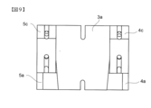
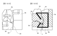
- FIG. 1 shows a monkey-shaped block-type deformable toy 1 as an animal-type block-type deformable toy of this embodiment.
- This monkey-shaped block-type deformable toy 1 has a plurality of blocks 2a, 3a to 3b, 4a to 4c constituting a head 2, a body 3, a right arm 4, a left arm 5, a right leg 6, and a left leg 7.
- a monkey is expressed by a combination of 5, 5a to 5c, 6a to 6c, and 7a to 7c.
- the block-type deformable toy of the prior art was designed as a humanoid robot, but in the example of the present invention, the blocks 2a, 3a to 3b, 4a to 4c, 5a to 5c, 6a to 6c, and 7a to 7c are used. It is possible to express a specific kind of animal by making it a complicated shape including how to combine them with each other.
- FIG. 2 is a plan view of this monkey-shaped block type deformable toy
- FIG. 3 is a rear view
- FIG. 4 is a bottom view
- FIG. 5 is a right side view.
- FIG. 6 shows a perspective view.
- each block 2a to 7c is urged in a direction close to each other by the first to third rubber cord members shown by 8a to 8c in the figure. That is, the first rubber cord member 8a extends from the block 2a constituting the head 2 to the block 3b forming the buttocks of the body 3 through the block 3a forming the body 3 and is formed at both ends.
- the head 2 and the body 3 are assembled by engaging the bumps with the blocks 2a and 3b at both ends.
- the rubber cord members 8a to 8c are actually embedded in the toy and cannot be seen from the outside, but are shown through in FIG.
- the second rubber cord member 8b extends from the block 4a constituting the hand of the right arm portion to the block 5a constituting the left arm portion through the blocks 4b, 4c, 3a, 5c and 5b, and is formed at both ends.
- the third rubber cord member 8c extends from the block 6a constituting the foot portion of the right leg portion to the block 7a constituting the left leg portion through the blocks 6b, 6c, 3b, 7c and 7b, and both ends. By engaging the bumps formed in the portions with the blocks 6a and 7a at both ends, the blocks 6a to 6c and 7a to 7c of both legs are assembled with respect to the blocks 3b of the body portion 3.
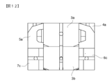
- FIG. 7 is a perspective view showing the folded state of the monkey-shaped block type deformable toy
- FIG. 8 is a side view
- FIG. 9 is a rear view
- FIG. 10 is a plan view
- FIG. 11 is a front view
- FIG. It shows the bottom view.
- At least two blocks out of the plurality of blocks have a state in which their two surfaces are in contact with each other at the same time, whereby the rotation around the elastic cord member is performed. It is configured so that movement is regulated.
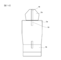
- the two blocks are a block 2a constituting the head 2 and a block 3a constituting the upper chest of the body 3.
- the lower surfaces 10 and 11 (two surfaces referred to in the claims) of the block 2a constituting the head 2 are tilted at an angle ⁇ of 160 degrees (see FIG. 14), and the body portion.
- the upper surfaces 12 and 13 that abut with the two surfaces of the head at the same time are 200 degrees (360 degrees minus the angle 160 degrees formed by the two lower surfaces 10 and 11 of the head 2). It is formed at an angle of (value).
- the extension line of the rubber cord member 8a can be seen from the state where the two surfaces are in contact with each other.
- the two surfaces 10, 11, 12, and 13 interfere with each other, and the blocks 2a and 3a of the above 2 are separated from each other (the direction indicated by the arrow ⁇ ). It will be driven against the urging force of the rubber cord member 8a.
- the rotation in the direction indicated by the arrow ⁇ is restricted, and when the hand is released, the position returns to the original position, that is, the position where the two surfaces 10, 11, 12, and 13 come into contact with each other. It is configured.
- FIG. 15 is a plan view of FIG. 13A
- FIG. 16 is a rear view.
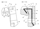
- 17A to 21 are views showing a state in which the three blocks 2a, 3a, and 3b shown in FIG. 13A are folded.
- the head 2 is folded as shown in FIG. 17A.
- two surfaces 15 and 16 that mesh with the two surfaces 10 and 11 formed on the head 2 are formed on the front surface of the block corresponding to the upper chest of the body 3 and these are formed with each other.
- the state of contact with each other is configured. That is, two adjacent surfaces 15 and 16 are formed on the upper chest of the body at an angle of 200 degrees so that the two surfaces 10/11 and 15/16 are in contact with each other. It has become.
- the head 2 is formed with slits 18 along the vertical direction in the back of the head. Further, the body portion 3 is formed with slits 19 that open in the directions of the upper surfaces 12 and 13 and the front surfaces 15 and 16. As a result, the rubber cord member 8a is routed without interfering with the blocks 2a and 3a, and as shown in FIG. 17B, the head 2 can be folded.
- a block 3b constituting the lower abdomen of the body is attached to the lower part of the block 3a to which the head 2 is attached to the body 3.
- the other end of the rubber cord member 8a is fixed to the block 3b.
- the two blocks 3a and 3b are in contact with each other on one surface 20 and 21, and in the state shown in FIGS. 13A and 13B, they can freely rotate around the rubber cord member 8a (arrow ⁇ ). In this respect, the rotation angle is not restricted because the head 2 is not in contact with each other on two surfaces as in the case of the head 2.
- the rear portion (buttocks) of the block 3b constituting the lower abdomen is provided with an inclined surface 22 inclined by about 15 degrees with respect to the direction of the rubber cord member 8a, and the abdomen of the block 3a constituting the body.
- An inclined surface 23 having the same angle is provided at a portion corresponding to the above. Then, when folding, the blocks 2 and 23 are brought into contact with each other so that the block 3b is urged upward (in the direction of arrow ⁇ ) along the inclination and brought into contact with the head 2 (2a). , The lower surface (shown in FIGS. 18A and 18B) when folded can be made flush with each other.
- the blocks 3a and 3b are provided with slits 24 and 25 over the surfaces 20, 21, 22 and 23, and the rubber cord member 8a does not interfere with the block when folded.
- the present invention is not limited to the above-mentioned embodiment and modification, and can be modified without changing the gist.
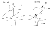
- FIGS. 22A and 22B are schematic views showing the head of a giraffe-type block-type deformable toy.
- the two blocks in which the two surfaces are in contact with each other at the same time are the block 26a forming the head 26 and the block 27a forming the upper end of the neck 27, as shown in FIGS. 13A and 13B.
- the displacement of the head 26 with respect to the neck 27 in the rotation direction is regulated. That is, in this modified example, the lower surfaces 28 and 29 (two surfaces referred to in the claims) of the block 26a constituting the head 26 are tilted at an angle ⁇ of 30 degrees (see FIG. 22B), and the neck portion 27.
- the upper surfaces 30 and 31 that abut with the two surfaces of the head at the same time are 330 degrees (360 degrees minus the angle of 30 degrees formed by the two lower surfaces 28 and 29 of the head 22). ) Is formed at an angle.
- the angle formed by the two surfaces of the block on the side having the sharpened portion is 30 degrees to 170 degrees. , 190 degrees to 330 degrees is preferable.
- the animal type block type deformed toy was a monkey, but it may be a giraffe as in the modified example, it may be another animal, or it may be a human type.
- animal type may be a block type deformed toy that expresses the form of an artificial object such as a passenger car or an airplane.
Landscapes
- Toys (AREA)
Abstract
[Problem] To provide a block-type transformable toy with which it is possible to realize complex shapes with design properties, e.g., various animal shapes, while ensuring a degree of freedom of folding. [Solution] Adjacent blocks are biased in directions of mutual contact using elastic cords, the adjacent blocks being changed so that surfaces having mutually different positional relationships are brought into contact with each other in resistance to the biasing force of the elastic cords, whereby the blocks can be transformed between a state of being folded so that the external shape becomes compact, and a state of being extended so as to take on the shape of an object to be expressed. Furthermore, at least two of the blocks among the plurality of blocks have a state in which two surfaces of each of the blocks simultaneously contact each other, the block-type transformable toy thereby being configured so that turning about the elastic cords is limited.
Description
この発明は、ブロック同士をゴム紐で連結して成る変形玩具に関するものである。
The present invention relates to a deformed toy formed by connecting blocks with a rubber string.
従来より、以下の特許文献1,2に示される人型ロボットのブロック式変形玩具がある。
Conventionally, there are block-type deformable toys for humanoid robots shown in Patent Documents 1 and 2 below.
これらの玩具は基本的に正六面体形状のブロック同士をゴム紐の付勢力によって集合させて変形玩具を構成するものである。すなわち、これらの変形玩具は、外形がボックス状になるように折り畳まれた状態と、人型ロボット形状になるように伸長された状態とに変形可能なものである。
These toys basically form a deformed toy by gathering blocks of regular hexahedron shape by the urging force of a rubber cord. That is, these deformable toys can be deformed into a state in which the outer shape is folded so as to have a box shape and a state in which the outer shape is extended so as to have a humanoid robot shape.
ところで、現在、デザイン性の高い複雑な形状を表現したブロック変形玩具はない。
By the way, at present, there is no block deformed toy that expresses a complicated shape with high design.
これは、従来のブロック式変形玩具は、遊戯性を高めるために人型ロボットに様々な姿勢を取らせることを重視していることによる。このため、多くの場合、六面体ブロックを用いるものであり、ブロックを構成する各面のなす角度は基本的に90度である。このような六面体ブロックを用いる場合、面同士で接するブロックを自由に回転させることができ、人型ロボットに様々な姿勢を取らせることができる。このため、例えば、頭の姿勢を実際にはありえない方向に向けたりできるものであり、且つ、これを許容しているため、デザイン性を高めるという思想がなかったものである。
This is because the conventional block-type deformable toys emphasize making the humanoid robot take various postures in order to enhance playability. Therefore, in many cases, a hexahedral block is used, and the angle formed by each surface forming the block is basically 90 degrees. When such a hexahedral block is used, the blocks in contact with each other can be freely rotated, and the humanoid robot can be made to take various postures. For this reason, for example, the posture of the head can be turned in an impossible direction in reality, and since this is allowed, there is no idea of enhancing the design.
この発明は、このような事情に鑑みてなされたものであり、折り畳みの自由度は確保しつつ、デザイン性の複雑な形状、例えば様々な動物形状を実現できるブロック式変形玩具を提供することを目的とする。
The present invention has been made in view of such circumstances, and provides a block-type deformable toy capable of realizing a complicated shape of design, for example, various animal shapes while ensuring the degree of freedom of folding. The purpose.
また、他の目的は、複雑な形状のブロックにより構成されたブロック式変形玩具を折り畳んだ際に、ブロック同士を確実に位置決めして纏まりのある外形を実現することが容易なブロック式変形玩具を提供することである。
Another purpose is to make a block-type deformable toy that can easily position the blocks to realize a cohesive outer shape when the block-type deformable toy composed of blocks having a complicated shape is folded. To provide.
上記課題を解決するため、この発明の主要な観点によれば、以下の発明が提供される。
(1) 複数のブロックの組み合わせにより対象物の形状を表現するブロック式変形玩具であり、
隣り合うブロックは、弾性紐材で互いに接する方向に付勢されており、
上記隣り合うブロック同士を、上記弾性紐材の付勢力に抗して互いの位置関係を異なる面同士が接するように変化させることで、外形がコンパクトになるように折り畳まれた状態と、表現する対象物の形状になるように伸長された状態とに変形可能であり、
さらに、
上記複数のブロックのうち、少なくとも2つのブロックは、それぞれの2つの面同士が互いに同時に接する状態を有し、それにより、上記弾性紐材周りの回動が規制されるように構成されているものである
ことを特徴とするブロック式変形玩具。
(2) 上記(1)記載のブロック式変形玩具において、
このブロック式変形玩具は、少なくとも、頭部、胴部、足部を複数のブロックの組み合わせにより表現する動物型ブロック式変形玩具である
ことを特徴とするブロック式変形玩具。
(3) 上記(1)記載のブロック式変形玩具において、
前記折り畳まれた状態は、外形がボックス状になるように構成されたものである
ことを特徴とするブロック式変形玩具。
(4) 上記(1)記載のブロック式変形玩具において、
前記2つの面のなす角度は、30度~170度、190度~330度である
ことを特徴とする動物型ブロック式変形玩具。
(5) 上記(1)記載のブロック式変形玩具において、
上記2つのブロックは、それぞれの2つの面同士が同時に接する状態を2以上有するものである
ことを特徴とするブロック式変形玩具。
(6) 上記(5)記載のブロック式変形玩具において、
上記2以上の状態は、それぞれ、折り畳まれた状態、伸長された状態である
ことを特徴とするブロック式変形玩具。
(7) 上記(2)記載の動物型ブロック式変形玩具において、
前記2つのブロックは、頭部と胴を構成するブロックであり、上記構成により、頭部の胴に対する回動方向の変位が規制されるものである
ことを特徴とするブロック式変形玩具。 In order to solve the above problems, the following inventions are provided according to the main viewpoint of the present invention.
(1) A block-type deformed toy that expresses the shape of an object by combining multiple blocks.
Adjacent blocks are urged by elastic cords in the direction of contact with each other.
The adjacent blocks are expressed as being folded so that the outer shape is compact by changing the positional relationship between the adjacent blocks so that different surfaces are in contact with each other against the urging force of the elastic cord material. It can be transformed into a stretched state so that it has the shape of an object.
further,
Of the plurality of blocks, at least two blocks are configured so that their two surfaces are in contact with each other at the same time, whereby the rotation around the elastic cord material is restricted. A block-type deformable toy characterized by being.
(2) In the block-type deformable toy described in (1) above,
This block-type deformable toy is a block-type deformable toy characterized in that at least the head, body, and feet are represented by a combination of a plurality of blocks.
(3) In the block-type deformable toy described in (1) above,
The folded state is a block-type deformable toy characterized in that the outer shape is configured to be box-shaped.
(4) In the block-type deformable toy described in (1) above,
An animal-type block-type deformable toy characterized in that the angles formed by the two surfaces are 30 degrees to 170 degrees and 190 degrees to 330 degrees.
(5) In the block-type deformable toy described in (1) above,
The block-type deformable toy is characterized in that the above two blocks have two or more states in which the two surfaces are in contact with each other at the same time.
(6) In the block-type deformable toy described in (5) above,
The above two or more states are block-type deformable toys characterized in that they are in a folded state and an extended state, respectively.
(7) In the animal type block type deformed toy described in (2) above,
The two blocks are blocks constituting the head and the body, and the block-type deformable toy is characterized in that the displacement of the head in the rotation direction with respect to the body is regulated by the above configuration.
なお、上記に記載した以外の特徴は以下の発明の実施形態の説明及び図面に開示されている。
Features other than those described above are disclosed in the following description and drawings of the embodiments of the present invention.
以下、本発明の一実施形態を添付図面を参照して説明する。
Hereinafter, an embodiment of the present invention will be described with reference to the accompanying drawings.
図1は、この実施形態の動物型ブロック式変形玩具として、猿型ブロック式変形玩具1を示すものである。
FIG. 1 shows a monkey-shaped block-type deformable toy 1 as an animal-type block-type deformable toy of this embodiment.
(伸長状態)
この猿型ブロック式変形玩具1は、頭部2、胴部3、右腕部4、左腕部5、右脚部6、左脚部7を構成する複数のブロック2a、3a~3b、4a~4c、5a~5c、6a~6c、7a~7cの組み合わせにより猿を表現するものである。従来技術のブロック式変形玩具は人型ロボットのデザインであったが、この発明の例では、上記各ブロック2a、3a~3b、4a~4c、5a~5c、6a~6c、7a~7cを、お互いの組み合わせ方を含めて複雑な形状とすることで特定の種類の動物を表現することが可能となったものである。 (Extended state)
This monkey-shaped block-type deformable toy 1 has a plurality of blocks 2a, 3a to 3b, 4a to 4c constituting a head 2, a body 3, a right arm 4, a left arm 5, a right leg 6, and a left leg 7. A monkey is expressed by a combination of 5, 5a to 5c, 6a to 6c, and 7a to 7c. The block-type deformable toy of the prior art was designed as a humanoid robot, but in the example of the present invention, the blocks 2a, 3a to 3b, 4a to 4c, 5a to 5c, 6a to 6c, and 7a to 7c are used. It is possible to express a specific kind of animal by making it a complicated shape including how to combine them with each other.
この猿型ブロック式変形玩具1は、頭部2、胴部3、右腕部4、左腕部5、右脚部6、左脚部7を構成する複数のブロック2a、3a~3b、4a~4c、5a~5c、6a~6c、7a~7cの組み合わせにより猿を表現するものである。従来技術のブロック式変形玩具は人型ロボットのデザインであったが、この発明の例では、上記各ブロック2a、3a~3b、4a~4c、5a~5c、6a~6c、7a~7cを、お互いの組み合わせ方を含めて複雑な形状とすることで特定の種類の動物を表現することが可能となったものである。 (Extended state)
This monkey-shaped block-
図2はこの猿型ブロック式変形玩具の平面図、図3は背面図、図4は底面図、図5は右側面図を示すものである。また、図6は、斜視図を示すものである。
FIG. 2 is a plan view of this monkey-shaped block type deformable toy, FIG. 3 is a rear view, FIG. 4 is a bottom view, and FIG. 5 is a right side view. Further, FIG. 6 shows a perspective view.
ここで、図3の背面図に示すように、各ブロック2a~7cは、図に8a~8cで示す第1~第3のゴム紐部材で互いに近接する方向に付勢されている。すなわち、第1のゴム紐部材8aは、頭部2を構成するブロック2aから、胴部3を構成するブロック3aを通して胴部3の臀部を構成するブロック3bまで延出され、両端部に作ったコブを上記両端のブロック2a、3bに係合させることで頭部2と胴部3を集合させている。なお、各ゴム紐部材8a~8cは、実際には玩具内に埋め込まれていて外から見えないが、この図3では透視して示しているものである。
Here, as shown in the rear view of FIG. 3, each block 2a to 7c is urged in a direction close to each other by the first to third rubber cord members shown by 8a to 8c in the figure. That is, the first rubber cord member 8a extends from the block 2a constituting the head 2 to the block 3b forming the buttocks of the body 3 through the block 3a forming the body 3 and is formed at both ends. The head 2 and the body 3 are assembled by engaging the bumps with the blocks 2a and 3b at both ends. The rubber cord members 8a to 8c are actually embedded in the toy and cannot be seen from the outside, but are shown through in FIG.
また、第2のゴム紐部材8bは、右腕部の手を構成するブロック4aから、ブロック4b、4c、3a、5c、5bを通して左腕部を構成するブロック5aにまで延出され、両端部に作ったコブを上記両端のブロック4c、5cに係合させることで両腕部4,5の各ブロック4a~4c、5a~5cを集合させて、かつ胴部3に取り付けている。
Further, the second rubber cord member 8b extends from the block 4a constituting the hand of the right arm portion to the block 5a constituting the left arm portion through the blocks 4b, 4c, 3a, 5c and 5b, and is formed at both ends. By engaging the humps with the blocks 4c and 5c at both ends, the blocks 4a to 4c and 5a to 5c of both arms 4 and 5 are assembled and attached to the body 3.
また、第3のゴム紐部材8cは、右脚部の足部を構成するブロック6aから、ブロック6b、6c、3b、7c、7bを通して左脚部を構成するブロック7aにまで延出され、両端部に作ったコブを上記両端のブロック6a、7aに係合させることで両脚部の各ブロック6a~6c、7a~7cを前記胴部3のブロック3bに対して集合させている。
Further, the third rubber cord member 8c extends from the block 6a constituting the foot portion of the right leg portion to the block 7a constituting the left leg portion through the blocks 6b, 6c, 3b, 7c and 7b, and both ends. By engaging the bumps formed in the portions with the blocks 6a and 7a at both ends, the blocks 6a to 6c and 7a to 7c of both legs are assembled with respect to the blocks 3b of the body portion 3.
(折り畳み状態)
そして、上記隣り合うブロック同士を、上記ゴム紐部材8a~8cの付勢力に抗して互いの位置関係を異なる面同士が接するように変化させることで、図1~図6に示すような伸長された状態からと、図7に示す折り畳まれた状態に変形可能である。 (Folded state)
Then, the adjacent blocks are stretched as shown in FIGS. 1 to 6 by changing the positional relationship between the adjacent blocks so that the different surfaces are in contact with each other against the urging force of therubber string members 8a to 8c. It can be transformed from the folded state to the folded state shown in FIG.
そして、上記隣り合うブロック同士を、上記ゴム紐部材8a~8cの付勢力に抗して互いの位置関係を異なる面同士が接するように変化させることで、図1~図6に示すような伸長された状態からと、図7に示す折り畳まれた状態に変形可能である。 (Folded state)
Then, the adjacent blocks are stretched as shown in FIGS. 1 to 6 by changing the positional relationship between the adjacent blocks so that the different surfaces are in contact with each other against the urging force of the
ここで、図7はこの猿型ブロック式変形玩具が折り畳まれた状態を示す斜視図、図8は側面図、図9は背面図、図10は平面図、図11は正面図、図12は底面図を示すものである。
Here, FIG. 7 is a perspective view showing the folded state of the monkey-shaped block type deformable toy, FIG. 8 is a side view, FIG. 9 is a rear view, FIG. 10 is a plan view, FIG. 11 is a front view, and FIG. It shows the bottom view.
(ブロック同士の組み合わせ)
さらに、請求の範囲に記載されたように、上記複数のブロックのうち、少なくとも2つのブロックは、それぞれの2つの面同士が互いに同時に接する状態を有し、それにより、上記ゴム紐部材周りの回動が規制されるように構成されているものである。 (Combination of blocks)
Further, as described in the claims, at least two blocks out of the plurality of blocks have a state in which their two surfaces are in contact with each other at the same time, whereby the rotation around the elastic cord member is performed. It is configured so that movement is regulated.
具体的には、この実施形態では、前記2つのブロックは、図13A、13Bに示すように、頭部2を構成するブロック2aと胴部3の上胸部を構成するブロック3aであり、この構成により、頭部2の胴3に対する回動方向の変位が規制されるものである。すなわち、この実施形態では、頭部2を構成するブロック2aの下面10、11(請求項にいう2つの面)は160度の角度θを成して傾いており(図14参照)、胴部3を構成するブロック3aには、上記頭部の2つの面と同時に当接する上面12,13が200度(360度から上記頭部2の2つの下面10,11のなす角度160度を引いた値)の角度を成して形成されている。
Specifically, in this embodiment, as shown in FIGS. 13A and 13B, the two blocks are a block 2a constituting the head 2 and a block 3a constituting the upper chest of the body 3. As a result, the displacement of the head 2 with respect to the body 3 in the rotation direction is regulated. That is, in this embodiment, the lower surfaces 10 and 11 (two surfaces referred to in the claims) of the block 2a constituting the head 2 are tilted at an angle θ of 160 degrees (see FIG. 14), and the body portion. On the block 3a constituting 3, the upper surfaces 12 and 13 that abut with the two surfaces of the head at the same time are 200 degrees (360 degrees minus the angle 160 degrees formed by the two lower surfaces 10 and 11 of the head 2). It is formed at an angle of (value).
そして上記2つのブロック2a、3aはゴム紐部材8aにより互いに当接する方向に付勢されているので、上述した2つの面同士が接触している状態から、上記ゴム紐部材8aの延長線回り(矢印αで示す方向)に回動させようとすると、上記2つの面10・11、12・13同士が干渉して、上記2のブロック2a、3aが互いに離れる方向(矢印βで示す方向)に上記ゴム紐部材8aの付勢力に抗して駆動されることになる。このことで、上記矢印αで示す方向の回動は規制されることになり、手を放すと元の位置、すなわち、2つの面10・11、12・13同士が当接する位置に戻るように構成されている。
Since the two blocks 2a and 3a are urged by the rubber cord member 8a in the direction of contact with each other, the extension line of the rubber cord member 8a can be seen from the state where the two surfaces are in contact with each other. When trying to rotate in the direction indicated by the arrow α, the two surfaces 10, 11, 12, and 13 interfere with each other, and the blocks 2a and 3a of the above 2 are separated from each other (the direction indicated by the arrow β). It will be driven against the urging force of the rubber cord member 8a. As a result, the rotation in the direction indicated by the arrow α is restricted, and when the hand is released, the position returns to the original position, that is, the position where the two surfaces 10, 11, 12, and 13 come into contact with each other. It is configured.
なお、図15は、図13Aの平面図、図16は背面図である。
Note that FIG. 15 is a plan view of FIG. 13A, and FIG. 16 is a rear view.
また、図17A~図21は、図13Aに示した3つのブロック2a、3a、3bを折り畳んだ状態を示す図である。
17A to 21 are views showing a state in which the three blocks 2a, 3a, and 3b shown in FIG. 13A are folded.
このように折り畳む際には、まず、頭部2を図17Aに示すように折り畳む。
When folding in this way, first, the head 2 is folded as shown in FIG. 17A.
この状態においても、上記胴部3の上胸部に対応するブロックの前面に上記頭部2に形成された2つの面10・11と噛み合う2つの面15・16が形成されており、これら同士が互いに接触する状態が構成されるようになっている。すなわち、上記胴部の上胸部には200度の角度を成して隣り合う2面15,16が構成されており、これにより、上記2つの面10・11、15・16同士が当接するようになっているのである。
Even in this state, two surfaces 15 and 16 that mesh with the two surfaces 10 and 11 formed on the head 2 are formed on the front surface of the block corresponding to the upper chest of the body 3 and these are formed with each other. The state of contact with each other is configured. That is, two adjacent surfaces 15 and 16 are formed on the upper chest of the body at an angle of 200 degrees so that the two surfaces 10/11 and 15/16 are in contact with each other. It has become.
なお、上記頭部2には、図13B、図16に示すように、後頭部に上下方向に沿うスリット18が形成されている。また、胴部3には、上記上面12・13と前面15・16の方向に開放するスリット19が形成されている。これにより、上記ゴム紐部材8aはブロック2a、3aと干渉することなく取り回され、図17Bに示すように、上記頭部2を折り畳めるようになっている。
As shown in FIGS. 13B and 16, the head 2 is formed with slits 18 along the vertical direction in the back of the head. Further, the body portion 3 is formed with slits 19 that open in the directions of the upper surfaces 12 and 13 and the front surfaces 15 and 16. As a result, the rubber cord member 8a is routed without interfering with the blocks 2a and 3a, and as shown in FIG. 17B, the head 2 can be folded.
また、図13A,Bに示すように、上記胴部3の、上記頭部2が取り付けられたブロック3aの下部には胴体下腹部を構成するブロック3bが取りつけられている。そして、このブロック3bは上記ゴム紐部材8aの他端部が固定されている。
Further, as shown in FIGS. 13A and 13B, a block 3b constituting the lower abdomen of the body is attached to the lower part of the block 3a to which the head 2 is attached to the body 3. The other end of the rubber cord member 8a is fixed to the block 3b.
この2つのブロック3a、3b同士は1面20・21で当接しており、図13A、13Bに示す状態では上記ゴム紐部材8a回り(矢印α)に自由に回動できるようになっている。この点、上記頭部2のように2面で接するものではないから回動角度が規制されることはない。
The two blocks 3a and 3b are in contact with each other on one surface 20 and 21, and in the state shown in FIGS. 13A and 13B, they can freely rotate around the rubber cord member 8a (arrow α). In this respect, the rotation angle is not restricted because the head 2 is not in contact with each other on two surfaces as in the case of the head 2.
一方、この下腹部を構成するブロック3bの後部(臀部)には上記ゴム紐部材8aの方向に対して約15度傾く傾斜面22が設けられていると共に、上記胴体を構成するブロック3aの腹部に対応する部分に同角度の傾斜面23が設けられている。そして、折り畳む際にはそれらの両面22,23同士を当接させることで、上記ブロック3bを傾斜に沿って上方向(矢印γ方向)に付勢して頭部2(2a)に当接させ、折り畳んだ際の下面(図18A,図18Bに示す)を面一にすることが可能になる。
On the other hand, the rear portion (buttocks) of the block 3b constituting the lower abdomen is provided with an inclined surface 22 inclined by about 15 degrees with respect to the direction of the rubber cord member 8a, and the abdomen of the block 3a constituting the body. An inclined surface 23 having the same angle is provided at a portion corresponding to the above. Then, when folding, the blocks 2 and 23 are brought into contact with each other so that the block 3b is urged upward (in the direction of arrow γ) along the inclination and brought into contact with the head 2 (2a). , The lower surface (shown in FIGS. 18A and 18B) when folded can be made flush with each other.
なお、上記ブロック3a、3bには、上記面20,21、22,23に亘ってスリット24,25が設けられており、折り畳む際にゴム紐部材8aがブロックに干渉することはない。
The blocks 3a and 3b are provided with slits 24 and 25 over the surfaces 20, 21, 22 and 23, and the rubber cord member 8a does not interfere with the block when folded.
このことで、図19~図21に示すように外形矩形状になるように位置決めして折り畳むことができるのである。
As a result, it can be positioned and folded so as to have a rectangular outer shape as shown in FIGS. 19 to 21.
(変形例)
また、本発明は上記の一実施例及び変形例に限定されるものではなく、要旨を変更しない範囲で変形可能である。 (Modification example)
Further, the present invention is not limited to the above-mentioned embodiment and modification, and can be modified without changing the gist.
また、本発明は上記の一実施例及び変形例に限定されるものではなく、要旨を変更しない範囲で変形可能である。 (Modification example)
Further, the present invention is not limited to the above-mentioned embodiment and modification, and can be modified without changing the gist.
例えば、図22A、図22Bは、キリン型ブロック式変形玩具の頭部を示す模式図である。
For example, FIGS. 22A and 22B are schematic views showing the head of a giraffe-type block-type deformable toy.
2つの面同士が互いに同時に接する2つのブロックは、この変形例では、図13A、13Bに示すように、頭部26を構成するブロック26aと首部27の上端部を構成するブロック27aであり、この構成により、図22Bに示すように、頭部26の首部27に対する回動方向の変位が規制されるものである。すなわち、この変形例では、頭部26を構成するブロック26aの下面28、29(請求項にいう2つの面)は30度の角度θを成して傾いており(図22B参照)、首部27を構成するブロック27aには、上記頭部の2つの面と同時に当接する上面30,31が330度(360度から上記頭部22の2つの下面28,29のなす角度30度を引いた値)の角度を成して形成されている。
In this modification, the two blocks in which the two surfaces are in contact with each other at the same time are the block 26a forming the head 26 and the block 27a forming the upper end of the neck 27, as shown in FIGS. 13A and 13B. Depending on the configuration, as shown in FIG. 22B, the displacement of the head 26 with respect to the neck 27 in the rotation direction is regulated. That is, in this modified example, the lower surfaces 28 and 29 (two surfaces referred to in the claims) of the block 26a constituting the head 26 are tilted at an angle θ of 30 degrees (see FIG. 22B), and the neck portion 27. The upper surfaces 30 and 31 that abut with the two surfaces of the head at the same time are 330 degrees (360 degrees minus the angle of 30 degrees formed by the two lower surfaces 28 and 29 of the head 22). ) Is formed at an angle.
なお、先鋭部を有する側のブロックの2つの面のなす角度が小さすぎるとこの部分が弱くなり、かつゴム紐を通すスペースがなくなるので、前記2つの面のなす角度は、30度~170度、190度~330度であることが好ましい。
If the angle formed by the two surfaces of the block on the side having the sharpened portion is too small, this portion becomes weak and there is no space for the rubber cord to pass through. Therefore, the angle formed by the two surfaces is 30 degrees to 170 degrees. , 190 degrees to 330 degrees is preferable.
また、上記一実施例では、動物型ブロック式変形玩具は猿であったが、変形例のようにキリンでも良いし、それ以外の動物でも良く、人間型であっても良い。
Further, in the above one embodiment, the animal type block type deformed toy was a monkey, but it may be a giraffe as in the modified example, it may be another animal, or it may be a human type.
さらに、動物型に限られるものではなく、例えば乗用車や飛行機などの人工物の形態を表現するブロック式変形玩具であっても良い。
Furthermore, it is not limited to the animal type, and may be a block type deformed toy that expresses the form of an artificial object such as a passenger car or an airplane.
1…ブロック式変形玩具
2…頭部
2a…ブロック
3…胴部
3a、3b…ブロック
4…右腕部
4a~4c…ブロック
5…左腕部
5a~5c…ブロック
6…右脚部
6a~6c…ブロック
7…左脚部
7a~7c…ブロック
8a~8c…第1~第3のゴム紐部材
10、11…頭部の下面
12、13…胴部の上面
15、16…胴部の前面
18…スリット
19…スリット
20…胴部の下面
21…臀部の上面
22、23…傾斜面
24…スリット
25…スリット
26…キリンの頭部
26a…ブロック
27…キリンの首部
27a…ブロック
28、29…キリンの頭部の下面
30、31…キリンの首部の上面 1 ... Block typedeformed toy 2 ... Head 2a ... Block 3 ... Torso 3a, 3b ... Block 4 ... Right arm 4a-4c ... Block 5 ... Left arm 5a-5c ... Block 6 ... Right leg 6a-6c ... Block 7 ... Left leg 7a-7c ... Block 8a-8c ... 1st to 3rd rubber cord members 10, 11 ... Lower surface of head 12, 13 ... Upper surface of body 15, 16 ... Front surface of body 18 ... Slit 19 ... Slit 20 ... Lower surface of the torso 21 ... Upper surface of the torso 22, 23 ... Inclined surface 24 ... Slit 25 ... Slit 26 ... Kirin's head 26a ... Block 27 ... Kirin's neck 27a ... Block 28, 29 ... Kirin's head Lower surface of the part 30, 31 ... Upper surface of the neck of the giraffe
2…頭部
2a…ブロック
3…胴部
3a、3b…ブロック
4…右腕部
4a~4c…ブロック
5…左腕部
5a~5c…ブロック
6…右脚部
6a~6c…ブロック
7…左脚部
7a~7c…ブロック
8a~8c…第1~第3のゴム紐部材
10、11…頭部の下面
12、13…胴部の上面
15、16…胴部の前面
18…スリット
19…スリット
20…胴部の下面
21…臀部の上面
22、23…傾斜面
24…スリット
25…スリット
26…キリンの頭部
26a…ブロック
27…キリンの首部
27a…ブロック
28、29…キリンの頭部の下面
30、31…キリンの首部の上面 1 ... Block type
Claims (7)
- 複数のブロックの組み合わせにより対象物の形状を表現するブロック式変形玩具であり、
隣り合うブロックは、弾性紐材で互いに接する方向に付勢されており、
上記隣り合うブロック同士を、上記弾性紐材の付勢力に抗して互いの位置関係を異なる面同士が接するように変化させることで、外形がコンパクトになるように折り畳まれた状態と、表現する対象物の形状になるように伸長された状態とに変形可能であり、
さらに、
上記複数のブロックのうち、少なくとも2つのブロックは、それぞれの2つの面同士が互いに同時に接する状態を有し、それにより、上記弾性紐材周りの回動が規制されるように構成されているものである
ことを特徴とするブロック式変形玩具。 It is a block-type deformed toy that expresses the shape of an object by combining multiple blocks.
Adjacent blocks are urged by elastic cords in the direction of contact with each other.
The adjacent blocks are expressed as being folded so that the outer shape is compact by changing the positional relationship between the adjacent blocks so that different surfaces are in contact with each other against the urging force of the elastic cord material. It can be transformed into a stretched state so that it has the shape of an object.
further,
Of the plurality of blocks, at least two blocks are configured so that their two surfaces are in contact with each other at the same time, whereby the rotation around the elastic cord material is restricted. A block-type deformable toy characterized by being. - 請求項1記載のブロック式変形玩具において、
このブロック式変形玩具は、少なくとも、頭部、胴部、足部を複数のブロックの組み合わせにより表現する動物型ブロック式変形玩具である
ことを特徴とするブロック式変形玩具。 In the block-type deformable toy according to claim 1,
This block-type deformable toy is a block-type deformable toy characterized in that at least the head, body, and feet are represented by a combination of a plurality of blocks. - 請求項1記載のブロック式変形玩具において、
前記折り畳まれた状態は、外形がボックス状になるように構成されたものである
ことを特徴とするブロック式変形玩具。 In the block-type deformable toy according to claim 1,
The folded state is a block-type deformable toy characterized in that the outer shape is configured to be box-shaped. - 請求項1記載のブロック式変形玩具において、
前記2つの面のなす角度は、30度~170度、190度~330度である
ことを特徴とする動物型ブロック式変形玩具。 In the block-type deformable toy according to claim 1,
An animal-type block-type deformable toy characterized in that the angles formed by the two surfaces are 30 degrees to 170 degrees and 190 degrees to 330 degrees. - 請求項1記載のブロック式変形玩具において、
上記2つのブロックは、それぞれの2つの面同士が同時に接する状態を2以上有するものである
ことを特徴とするブロック式変形玩具。 In the block-type deformable toy according to claim 1,
The block-type deformable toy is characterized in that the above two blocks have two or more states in which the two surfaces are in contact with each other at the same time. - 請求項5記載のブロック式変形玩具において、
上記2以上の状態は、それぞれ、折り畳まれた状態、伸長された状態である
ことを特徴とするブロック式変形玩具。 In the block-type deformable toy according to claim 5.
The above two or more states are block-type deformable toys characterized in that they are in a folded state and an extended state, respectively. - 請求項2記載の動物型ブロック式変形玩具において、
前記2つのブロックは、頭部と胴を構成するブロックであり、上記構成により、頭部の胴に対する回動方向の変位が規制されるものである
ことを特徴とするブロック式変形玩具。 In the animal type block type deformable toy according to claim 2.
The two blocks are blocks constituting the head and the body, and the block-type deformable toy is characterized in that the displacement of the head in the rotation direction with respect to the body is regulated by the above configuration.
Priority Applications (4)
| Application Number | Priority Date | Filing Date | Title |
|---|---|---|---|
| EP20887250.7A EP4059585A4 (en) | 2019-11-12 | 2020-11-11 | Block-type transformable toy |
| JP2021556120A JP7140434B2 (en) | 2019-11-12 | 2020-11-11 | block type transforming toy |
| CN202080048746.3A CN114072212A (en) | 2019-11-12 | 2020-11-11 | Building block type deformable toy |
| US17/628,116 US20220274031A1 (en) | 2019-11-12 | 2020-11-11 | Block-type transformable toy |
Applications Claiming Priority (2)
| Application Number | Priority Date | Filing Date | Title |
|---|---|---|---|
| US201962934342P | 2019-11-12 | 2019-11-12 | |
| US62/934,342 | 2019-11-12 |
Publications (1)
| Publication Number | Publication Date |
|---|---|
| WO2021095765A1 true WO2021095765A1 (en) | 2021-05-20 |
Family
ID=75912689
Family Applications (1)
| Application Number | Title | Priority Date | Filing Date |
|---|---|---|---|
| PCT/JP2020/042068 WO2021095765A1 (en) | 2019-11-12 | 2020-11-11 | Block-type transformable toy |
Country Status (5)
| Country | Link |
|---|---|
| US (1) | US20220274031A1 (en) |
| EP (1) | EP4059585A4 (en) |
| JP (1) | JP7140434B2 (en) |
| CN (1) | CN114072212A (en) |
| WO (1) | WO2021095765A1 (en) |
Cited By (1)
| Publication number | Priority date | Publication date | Assignee | Title |
|---|---|---|---|---|
| WO2023122686A1 (en) * | 2021-12-22 | 2023-06-29 | Grimes Brad | Action figures and building blocks |
Citations (10)
| Publication number | Priority date | Publication date | Assignee | Title |
|---|---|---|---|---|
| JPS6142995U (en) * | 1984-08-23 | 1986-03-20 | 一躬 竹内 | continuous block |
| JPH0228297U (en) * | 1988-08-11 | 1990-02-23 | ||
| JP3015685U (en) * | 1995-03-10 | 1995-09-05 | 有限会社ファインデザイン | Picture matching block toy |
| JPH09155068A (en) * | 1995-12-06 | 1997-06-17 | Toshiya Urabe | Assembly structure provided with dynamic change |
| US6482063B1 (en) | 1999-11-18 | 2002-11-19 | Charles Raymond Frigard | Articulating blocks toy |
| US20100221975A1 (en) * | 2009-02-16 | 2010-09-02 | Kimbrough Richard R | Transformable Jewelry and Decorative Structures |
| US20120156960A1 (en) | 2010-12-21 | 2012-06-21 | David Weeks Studio LLC | Transformable Toy Robot |
| US20160136531A1 (en) * | 2014-11-18 | 2016-05-19 | Virginie MANICHON | Articulated toy robot with frame, base, building accessories, and kits therefor |
| US20170106302A1 (en) * | 2015-01-16 | 2017-04-20 | Kma Concepts Limited | Toy Figure with Articulating Limbs and Body |
| US20180184768A1 (en) * | 2017-01-05 | 2018-07-05 | Richard R. Kimbrough | Transformable Jewelry and Decorative Structures |
Family Cites Families (7)
| Publication number | Priority date | Publication date | Assignee | Title |
|---|---|---|---|---|
| US957666A (en) * | 1909-05-25 | 1910-05-10 | George Washington Ferguson | Jointed figure. |
| US3577673A (en) * | 1968-01-31 | 1971-05-04 | Ottorino Monestier | Block elements of variable angular form |
| USD306621S (en) * | 1987-10-30 | 1990-03-13 | Takara Co., Ltd. | Reconfigurable toy cassette |
| US4997375A (en) * | 1989-12-18 | 1991-03-05 | Heinz Ted L | Elastically interconnected articulated blocks |
| US5302148A (en) * | 1991-08-16 | 1994-04-12 | Ted Heinz | Rotatable demountable blocks of several shapes on a central elastic anchor |
| CN204395434U (en) * | 2015-01-16 | 2015-06-17 | 东莞市诺峰实业有限公司 | One is toy robot flexibly |
| US10035076B2 (en) * | 2016-09-21 | 2018-07-31 | Mga Entertainment, Inc. | Transformer toy with rolling vehicle integrated into command center |
-
2020
- 2020-11-11 US US17/628,116 patent/US20220274031A1/en active Pending
- 2020-11-11 EP EP20887250.7A patent/EP4059585A4/en active Pending
- 2020-11-11 WO PCT/JP2020/042068 patent/WO2021095765A1/en unknown
- 2020-11-11 CN CN202080048746.3A patent/CN114072212A/en active Pending
- 2020-11-11 JP JP2021556120A patent/JP7140434B2/en active Active
Patent Citations (10)
| Publication number | Priority date | Publication date | Assignee | Title |
|---|---|---|---|---|
| JPS6142995U (en) * | 1984-08-23 | 1986-03-20 | 一躬 竹内 | continuous block |
| JPH0228297U (en) * | 1988-08-11 | 1990-02-23 | ||
| JP3015685U (en) * | 1995-03-10 | 1995-09-05 | 有限会社ファインデザイン | Picture matching block toy |
| JPH09155068A (en) * | 1995-12-06 | 1997-06-17 | Toshiya Urabe | Assembly structure provided with dynamic change |
| US6482063B1 (en) | 1999-11-18 | 2002-11-19 | Charles Raymond Frigard | Articulating blocks toy |
| US20100221975A1 (en) * | 2009-02-16 | 2010-09-02 | Kimbrough Richard R | Transformable Jewelry and Decorative Structures |
| US20120156960A1 (en) | 2010-12-21 | 2012-06-21 | David Weeks Studio LLC | Transformable Toy Robot |
| US20160136531A1 (en) * | 2014-11-18 | 2016-05-19 | Virginie MANICHON | Articulated toy robot with frame, base, building accessories, and kits therefor |
| US20170106302A1 (en) * | 2015-01-16 | 2017-04-20 | Kma Concepts Limited | Toy Figure with Articulating Limbs and Body |
| US20180184768A1 (en) * | 2017-01-05 | 2018-07-05 | Richard R. Kimbrough | Transformable Jewelry and Decorative Structures |
Cited By (1)
| Publication number | Priority date | Publication date | Assignee | Title |
|---|---|---|---|---|
| WO2023122686A1 (en) * | 2021-12-22 | 2023-06-29 | Grimes Brad | Action figures and building blocks |
Also Published As
| Publication number | Publication date |
|---|---|
| CN114072212A (en) | 2022-02-18 |
| EP4059585A4 (en) | 2023-11-15 |
| JP7140434B2 (en) | 2022-09-21 |
| US20220274031A1 (en) | 2022-09-01 |
| JPWO2021095765A1 (en) | 2021-05-20 |
| EP4059585A1 (en) | 2022-09-21 |
Similar Documents
| Publication | Publication Date | Title |
|---|---|---|
| US9993739B2 (en) | Transformable toy robot | |
| WO2021095765A1 (en) | Block-type transformable toy | |
| JP6774540B1 (en) | Joint structure and doll body | |
| JP4452611B2 (en) | Connectable elements for structure assembly sets | |
| US20200246717A1 (en) | Building toy | |
| CN108583720A (en) | Four-footed bionic robot with eight-rod metamorphic mechanism at waist and driving method | |
| US3740128A (en) | Amusement device | |
| KR20110080921A (en) | Robot hand | |
| WO2024062970A1 (en) | Model toy and movable structure | |
| JP5221790B2 (en) | Arm model arm structure | |
| JP7360566B1 (en) | Model toys and movable structures | |
| CN114307178B (en) | Humanoid body and rotating mechanism | |
| US6929527B1 (en) | Doll and infrastructure therein | |
| JP2012011032A (en) | Transforming robot toy | |
| TWI326613B (en) | ||
| US839770A (en) | Toy. | |
| JP2022182793A (en) | Model component and articulated structure | |
| JP2021023830A (en) | Joint structure and doll body | |
| CN114534267B (en) | Connecting member for human-shaped toy and model | |
| WO2017130923A1 (en) | Wooden figure | |
| JP3194827U (en) | Assembled 3D toy | |
| KR102407993B1 (en) | Block toys | |
| US546791A (en) | Joint for dolls | |
| JP7474897B1 (en) | Model toys and jointed structures | |
| KR200470226Y1 (en) | Trunk part of jointed doll |
Legal Events
| Date | Code | Title | Description |
|---|---|---|---|
| 121 | Ep: the epo has been informed by wipo that ep was designated in this application |
Ref document number: 20887250 Country of ref document: EP Kind code of ref document: A1 |
|
| ENP | Entry into the national phase |
Ref document number: 2021556120 Country of ref document: JP Kind code of ref document: A |
|
| NENP | Non-entry into the national phase |
Ref country code: DE |
|
| ENP | Entry into the national phase |
Ref document number: 2020887250 Country of ref document: EP Effective date: 20220613 |