WO2021095528A1 - Dissimilar material solid phase bonding method, dissimilar material solid phase bonded structure, and dissimilar material solid phase bonding device - Google Patents
Dissimilar material solid phase bonding method, dissimilar material solid phase bonded structure, and dissimilar material solid phase bonding device Download PDFInfo
- Publication number
- WO2021095528A1 WO2021095528A1 PCT/JP2020/040395 JP2020040395W WO2021095528A1 WO 2021095528 A1 WO2021095528 A1 WO 2021095528A1 JP 2020040395 W JP2020040395 W JP 2020040395W WO 2021095528 A1 WO2021095528 A1 WO 2021095528A1
- Authority
- WO
- WIPO (PCT)
- Prior art keywords
- interface
- bonding
- insert material
- solid phase
- temperature
- Prior art date
Links
Images


Classifications
-
- B—PERFORMING OPERATIONS; TRANSPORTING
- B23—MACHINE TOOLS; METAL-WORKING NOT OTHERWISE PROVIDED FOR
- B23K—SOLDERING OR UNSOLDERING; WELDING; CLADDING OR PLATING BY SOLDERING OR WELDING; CUTTING BY APPLYING HEAT LOCALLY, e.g. FLAME CUTTING; WORKING BY LASER BEAM
- B23K20/00—Non-electric welding by applying impact or other pressure, with or without the application of heat, e.g. cladding or plating
- B23K20/12—Non-electric welding by applying impact or other pressure, with or without the application of heat, e.g. cladding or plating the heat being generated by friction; Friction welding
-
- B—PERFORMING OPERATIONS; TRANSPORTING
- B23—MACHINE TOOLS; METAL-WORKING NOT OTHERWISE PROVIDED FOR
- B23K—SOLDERING OR UNSOLDERING; WELDING; CLADDING OR PLATING BY SOLDERING OR WELDING; CUTTING BY APPLYING HEAT LOCALLY, e.g. FLAME CUTTING; WORKING BY LASER BEAM
- B23K20/00—Non-electric welding by applying impact or other pressure, with or without the application of heat, e.g. cladding or plating
- B23K20/16—Non-electric welding by applying impact or other pressure, with or without the application of heat, e.g. cladding or plating with interposition of special material to facilitate connection of the parts, e.g. material for absorbing or producing gas
-
- B—PERFORMING OPERATIONS; TRANSPORTING
- B23—MACHINE TOOLS; METAL-WORKING NOT OTHERWISE PROVIDED FOR
- B23K—SOLDERING OR UNSOLDERING; WELDING; CLADDING OR PLATING BY SOLDERING OR WELDING; CUTTING BY APPLYING HEAT LOCALLY, e.g. FLAME CUTTING; WORKING BY LASER BEAM
- B23K20/00—Non-electric welding by applying impact or other pressure, with or without the application of heat, e.g. cladding or plating
- B23K20/12—Non-electric welding by applying impact or other pressure, with or without the application of heat, e.g. cladding or plating the heat being generated by friction; Friction welding
- B23K20/1205—Non-electric welding by applying impact or other pressure, with or without the application of heat, e.g. cladding or plating the heat being generated by friction; Friction welding using translation movement
-
- B—PERFORMING OPERATIONS; TRANSPORTING
- B23—MACHINE TOOLS; METAL-WORKING NOT OTHERWISE PROVIDED FOR
- B23K—SOLDERING OR UNSOLDERING; WELDING; CLADDING OR PLATING BY SOLDERING OR WELDING; CUTTING BY APPLYING HEAT LOCALLY, e.g. FLAME CUTTING; WORKING BY LASER BEAM
- B23K20/00—Non-electric welding by applying impact or other pressure, with or without the application of heat, e.g. cladding or plating
- B23K20/22—Non-electric welding by applying impact or other pressure, with or without the application of heat, e.g. cladding or plating taking account of the properties of the materials to be welded
- B23K20/227—Non-electric welding by applying impact or other pressure, with or without the application of heat, e.g. cladding or plating taking account of the properties of the materials to be welded with ferrous layer
- B23K20/2275—Non-electric welding by applying impact or other pressure, with or without the application of heat, e.g. cladding or plating taking account of the properties of the materials to be welded with ferrous layer the other layer being aluminium
-
- B—PERFORMING OPERATIONS; TRANSPORTING
- B23—MACHINE TOOLS; METAL-WORKING NOT OTHERWISE PROVIDED FOR
- B23K—SOLDERING OR UNSOLDERING; WELDING; CLADDING OR PLATING BY SOLDERING OR WELDING; CUTTING BY APPLYING HEAT LOCALLY, e.g. FLAME CUTTING; WORKING BY LASER BEAM
- B23K2103/00—Materials to be soldered, welded or cut
- B23K2103/18—Dissimilar materials
- B23K2103/20—Ferrous alloys and aluminium or alloys thereof
Definitions
- the present invention relates to a dissimilar material solid phase bonding method for solid-phase bonding of metal materials, a dissimilar material solid phase bonding structure obtained by the dissimilar material solid phase bonding method, and a dissimilar material solid phase bonding device used for the dissimilar material solid phase bonding method.
- Patent Document 1 International Publication No. 2017/022184
- Patent Document 1 International Publication No. 2017/022184
- the surfaces to be joined of two metal materials to be joined are slid in contact with each other, and the metal joint is made of metal.
- a friction joining method characterized in that at least one of the materials is an iron-based material and the maximum temperature reached during joining is set to A 3 points or less or A cm points or less of the iron-based material.
- the conventional friction stir welding is a bonding method using frictional heat, but in the friction stir welding method described in Patent Document 1, the processing heat generated by the plastic deformation of the metal material to be welded is positively utilized. A good joint can be obtained even at a low joint temperature.
- Patent Document 2 Japanese Unexamined Patent Publication No. 2018-12234
- one member and the other member are repeatedly slid on the same locus to discharge burrs from the interface to be joined, and a third step of stopping sliding to form a joint surface.
- a linear frictional bonding method characterized in that the pressure is set to be equal to or greater than the yield stress of one member and / or the other member and equal to or less than the tensile strength at a desired bonding temperature. ..
- the relationship between the yield strength and the temperature is substantially constant depending on the material, and the bonding is performed extremely accurately by the applied pressure for discharging burrs from the interface to be bonded.
- the temperature can be controlled.
- an object of the present invention is to provide a dissimilar solid phase joint capable of efficiently forming a strong joint portion of metal materials having different compositions.
- the present invention also provides a dissimilar solid phase bonding structure having a dissimilar solid phase bonding portion in which metal materials having different compositions are firmly bonded, and a dissimilar solid phase bonding device for obtaining the dissimilar solid phase bonding structure. It is also aimed at.
- the present inventor has conducted intensive studies on the deformation behavior of the material to be bonded in the vicinity of the interface to be bonded during solid phase bonding of dissimilar materials.
- the bonding temperature is controlled by setting individual bonding pressures at the interface between the insert material and one material to be bonded and the interface between the insert material and the other material to be bonded, and the composition differs through the insert material.
- the present invention A solid-phase joining method for joining one member and the other member.
- the composition of the one member and the other member are different.
- the interface (1) to be joined in which one member and the other member are brought into contact with each other via an insert material, and the other member and the insert material are in contact with each other, and the other member and the insert material.
- the temperature of the interface to be joined (1) and the interface to be joined (2) is raised by frictional heat due to sliding of the one member and the other member and the insert material, and / or energization heating.
- a bonding pressure (1) is applied substantially perpendicular to the interface (1) to be bonded.
- a bonding pressure (2) is applied substantially perpendicular to the interface (2) to be bonded. Setting the bonding pressure (1) and the bonding pressure (2) to different values, Provided is a method for solid-phase bonding of dissimilar materials, which is characterized by the above.
- one member having a different composition and the other member are bonded, but not only when the main elements are different, such as a steel member and a titanium alloy member, but also steels having different compositions. It can be applied to a combination having the same main element but different additive elements, such as a member.
- the dissimilar material solid phase joining method of the present invention is a method of joining members having different compositions via an insert material, and the insert material has "a temperature at which the strength becomes substantially the same" as that of one member and the other member. Is preferable.
- the interface to be bonded (1) is formed by performing solid phase bonding at a temperature at which the strength of the insert material and one member and the strength of the insert material and the other member are substantially the same.
- substantially the same strength does not mean that the strengths are completely the same, and it may be a strength range in which the formation of the new surface at the interface to be joined proceeds to the same extent. Therefore, a difference of about several tens of MPa is allowed for "substantially the same strength".
- the object can be achieved by appropriately setting the bonding load applied substantially perpendicular to the interface to be bonded. it can.
- the bonding load applied substantially perpendicular to the interface to be bonded.
- increasing the applied pressure of linear friction stir welding increases the frictional heat, but the softened material becomes burrs and is continuously discharged, so it is applied to the softened material.
- the "bonding temperature" is determined by the pressure (force to discharge burrs). That is, when the applied pressure is set high, the material to be joined with higher strength (state in which the yield strength is high) can be discharged as burrs.
- the "state of higher yield strength” means the "state of lower temperature”
- the "joining temperature” is lowered by the increase of the applied pressure. Since the relationship between the yield strength and the temperature is substantially constant depending on the material, the junction temperature can be controlled extremely accurately.
- the temperature of the interface to be bonded (1) and the interface to be bonded (2) is raised by energization heating, control of the bonding temperature by the bonding pressure can be similarly achieved, and the bonding temperature is softened by the applied bonding pressure. Since the material becomes burrs and is continuously discharged, the "bonding temperature" is determined by the pressure (force to discharge burrs) applied to the softened material. When energization heating is used, the temperature does not necessarily have to be the same because it is affected by the electrical resistance of the metal.
- the method for raising the temperature in the vicinity of the interface to be joined is not particularly limited as long as the effect of the present invention is not impaired, and various conventionally known raising methods (bonding methods) can be used.
- “friction pressure welding” in which a rotating cylindrical material to be joined is pressed against a fixed material to be joined
- linear friction welding in which the material to be joined is reciprocally moved in contact with the material to be joined.
- energization heating, high frequency heating, laser heating, flame heating, or a combination thereof may be used.
- the insert material may be moved (sliding) in a state where one member and the other member are brought into contact with each other via the insert material, and one member and the other member may be moved (sliding). You may. Further, when the one member and the other member are rotated by friction welding, the one member and the other member may be rotated in opposite directions.
- the joining temperature is preferably set to temperature (1) and / or temperature (2), but it is not always necessary to set the joining temperature to the same value, and a new surface of the insert material and the joined material is formed at the interface to be joined. For example, joining can be achieved. It is also preferable to pay attention to the influence of the sizes of the material to be joined and the insert material on the joining temperature.
- the greatest feature of the dissimilar solid phase bonding method of the present invention is the interface to be bonded (1) where one member and the insert material are in contact with each other and the interface to be bonded (2) where the other member and the insert material are in contact with each other.
- the joining pressure (joining pressure (1) and joining pressure (2)) is applied substantially perpendicularly to each of the above, and the joining pressure (1) and the joining pressure (2) are set to different values.
- the bonding pressure (1) is set to a value equal to or greater than the yield stress of the insert material and the one member at the temperature (1) and equal to or less than the tensile strength, and the bonding pressure (2).
- the bonding temperature is basically determined by the combination of one member, the other member and the insert material, but when an iron-based metal is used as the material to be bonded, the bonding temperature is determined. Is preferably A 1 point or less of the iron-based metal. In iron-based metals, brittle martensite is formed by phase transformation, and there are cases where joining is difficult and cases where the joining portion becomes brittle. On the other hand, when the bonding temperature is set to A 1 point or less, phase transformation does not occur, so that the formation of brittle martensite can be completely suppressed.
- the bonding temperature is preferably set to be equal to or lower than the ⁇ transus temperature of the titanium alloy.
- the bonding temperature is preferably set to be equal to or lower than the ⁇ transus temperature of the titanium alloy.
- the bonding temperature may be adjusted by applying external cooling and / or external heating to the one member and / or the other member.
- external cooling and / or external heating it is possible to control the deformation of one member and / or the discharge of burrs in the vicinity of the interface to be joined.
- one of the members is an aluminum alloy member and the other member is an iron-based metal member, a copper-based metal member or a titanium-based metal member.
- a fragile intermetallic compound layer is likely to be formed at the bonding interface between the aluminum alloy and these metal members, and it is extremely difficult to obtain a joint having high mechanical properties.
- the material to be joined with weak strength is unilaterally deformed, and it is difficult to form a new surface of the material to be joined with high strength.
- the aluminum alloy and the insert material, and the iron-based metal (copper-based metal, titanium-based metal) and the insert material can be solid-phase bonded by abutting between the new surfaces. Not only can the new surfaces be joined together, but a good joint in which the formation of intermetallic compounds is suppressed can be obtained.
- the iron-based metal means a metal mainly composed of iron in its composition, and includes, for example, various steels and cast iron.
- the copper-based metal means a metal mainly composed of copper in the composition
- the titanium-based metal means a metal mainly composed of titanium in the composition.
- the present invention has a solid phase joint in which one member and the other member are integrated via an insert material. At least one of the one member and the other member has a composition different from that of the insert material. At the joining interface (1) where the one member and the insert material are in contact with each other, both the one member and the insert material are deformed. At the joining interface (2) where the other member and the insert material are in contact with each other, both the other member and the insert material are deformed. Also provided is a dissimilar solid phase bonding structure.
- both the one member and the insert material are deformed, and the other member and the insert material are separated from each other.
- the other member and the insert material are both deformed.
- the new surface of the insert material generated by deformation and the new surface of each member are in contact with each other to form a good joint interface.
- the "deformation” includes the formation of burrs, plastic deformation, and the like, but the "deformation” in the present invention means the one accompanied by the formation of a new surface at the joint interface.
- the degree of deformation of one member, the other member, and the insert material is not particularly limited as long as the bonding by contact between the new surfaces is achieved, but the bonding by contact between the new surfaces is achieved over the entire surface to be joined. Is preferable.
- the area of the surface to be bonded after deformation, including the portion discharged as burrs, should be at least twice the original area. It is preferable to do so.
- one of the members is an aluminum alloy member and the other member is an iron-based metal member, a copper-based metal member or a titanium-based member.
- a fragile intermetallic compound layer is likely to be formed at the bonding interface between an aluminum alloy and these metals, and it is extremely difficult to obtain a joint having high mechanical properties.
- the aluminum alloy and the insert material, and various metals and the insert material can be solid-phase bonded by abutting each of the new surfaces, so that the formation of the intermetallic compound is suppressed. Can be obtained.
- the thickness of the intermetallic compound layer at the bonding interface (1) and the bonding interface (2) is less than 1 ⁇ m. It is known that when a thick intermetallic compound layer is formed at the bonding interface, the mechanical properties of the joint such as tensile strength and toughness are significantly reduced. Since the thickness of the intermetallic compound layer is less than 1 ⁇ m at both the bonding interface (1) and the bonding interface (2), high mechanical properties can be ensured.
- the thickness of the intermetallic compound layer at the bonding interface (1) and the bonding interface (2) is preferably less than 500 nm over the entire solid phase bonding interface, and more preferably less than 300 nm. It is preferably less than 100 nm, most preferably less than 100 nm.
- the solid-phase bonding interface has high strength, and the bonded portion can exhibit excellent mechanical properties (strength, toughness, etc.).
- the solid phase bonding interface contains recrystallized grains. Since the structure near the bonding interface becomes fine equiaxed recrystallized grains, it is possible to obtain a bonded portion having excellent mechanical properties such as strength, toughness, and reliability.
- the dissimilar solid phase bonding structure of the present invention can be suitably obtained by using the dissimilar solid phase bonding method of the present invention.
- the present invention A solid-phase joining device that joins one member and the other member.
- the interface (1) to be joined in which one member and the other member are brought into contact with each other via an insert material, and the other member and the insert material are in contact with each other, and the other member and the insert material.
- a sliding mechanism that rotates, and / or an energization heating mechanism that energizes and heats the interface to be joined (1) and the interface to be joined (2).
- the bonding pressure (1) is applied substantially perpendicular to the interface to be bonded (1)
- the bonding pressure (2) is applied substantially perpendicular to the interface to be bonded (2)
- the bonding pressure (1) is applied.
- a pressing mechanism capable of setting the bonding pressure (2) to different values. Also provided is a dissimilar solid phase bonding apparatus.
- the dissimilar material solid phase bonding device of the present invention is a device that can be suitably used for obtaining the dissimilar material solid phase bonding structure of the present invention by the dissimilar material solid phase bonding method of the present invention.
- a "grasping mechanism”, a “sliding mechanism and / or an energizing heating mechanism” and a “pressing mechanism” are indispensable.
- the biggest feature is that 2) can be set to different values.
- the specific method for setting the joining pressure (1) and the joining pressure (2) to different values is not particularly limited as long as the effect of the present invention is not impaired. It may be fixed at a reference site different from the other member), and different joining pressures may be applied from both sides of the insert material fixed independently. Further, a pressing mechanism may be separately provided at the portion where the insert material is fixed.
- the insert material may be connected to the vibrating portion and different bonding pressures may be applied from the left and right sides of the insert material.
- the dissimilar material solid phase bonding apparatus of the present invention When there is a temperature (1) at which the insert material and the one member have substantially the same strength, and there is a temperature (2) at which the insert material and the other member have substantially the same strength.
- a value equal to or greater than the yield stress of the insert material and the one member at the temperature (1) and equal to or less than the tensile strength can be applied to the interface to be joined (1) as the bonding pressure (1).
- a value of yield strength or more and tensile strength or less of the insert material and the other member at the temperature (2) can be applied to the interface to be joined (2) as the bonding pressure (2). Is preferable.
- the pressure at the time of solid phase bonding is equal to or higher than the yield stress of the material to be bonded, the discharge of burrs from the interface to be bonded is started, and when the pressure is increased up to the tensile strength, the discharge of burrs is accelerated. It will be. Similar to the yield stress, the tensile strength at a specific temperature is substantially constant depending on the material to be bonded, so that the bonding temperature corresponding to the set pressure can be realized. As long as the effect of the present invention is not impaired, the method of applying the bonding pressure is not particularly limited, and various conventionally known methods can be used.
- the temperatures in the vicinity of the interface to be bonded (1) and the interface to be bonded (2) during bonding and the bonding load are measured, and the measured temperature and the bonding conditions obtained are used. It is preferable to compare the predicted joining temperatures and increase the joining load when the measured temperature is higher than the predicted joining temperature and decrease the joining load when the measured temperature is lower than the joining temperature. By having the feedback mechanism, the junction temperature can be controlled more accurately.
- a dissimilar material solid phase joint capable of efficiently forming a strong joint portion of metal materials having different compositions.
- a dissimilar solid phase bonding structure having a dissimilar solid phase bonding portion in which metal materials having different compositions are firmly bonded and a dissimilar solid phase bonding device for obtaining the dissimilar solid phase bonding structure are provided. It can also be provided.
- FIG. 1 shows a schematic diagram showing a general situation during linear friction bonding.
- Linear friction stir welding is a solid phase welding in which the frictional heat generated when the materials to be welded are rubbed against each other by linear motion is the main heat source.
- the material softened by the temperature rise is discharged as burrs from the interface to be welded to remove the oxide film formed at the interface to be welded, and the new surfaces are brought into contact with each other to bring the joints into contact with each other. Is said to be obtained.
- FIG. 2 schematically shows the relationship between the state during bonding and the bonding temperature of the dissimilar solid phase bonding method of the present invention.
- one member 2 and the other member 4 having different compositions are brought into contact with each other via the insert material 6, and one member 2 and the insert material 6 are brought into contact with each other.
- An interface (1) and an interface (2) to be joined in which the other member 4 and the insert material 6 are in contact with each other are formed.
- the bonding pressure (1) is applied substantially perpendicular to the interface to be bonded (1)
- the bonding pressure (2) is applied substantially perpendicular to the interface to be bonded (2)
- the bonding pressure (1) is applied.
- the joint pressure (2) are set to different values.
- the graph shown on the upper side of FIG. 2 schematically shows the temperature dependence of the strength of one member 2, the other member 4, and the insert material 6.
- the line showing the temperature dependence of the strength of the insert material 6 intersects with the line showing the temperature dependence of the strength of one member 2 and the line showing the temperature dependence of the strength of the other member 4.
- the joining pressure (1) corresponding to the intersection of one member 2 and the insert material 6 is applied, and at the interface to be joined (2), the intersection of the other member 4 and the insert material 6 is applied.
- the joining pressure (2) corresponding to the above may be set.
- the temperature-dependent relationship of the strength shown in FIG. 2 is an example.
- a combination of the material to be joined and the insert material 6 having the temperature dependence of the strength as shown in FIG. 3 may be used.
- the insert material 6 may have an "intersection" with one member 2 and the other member 4, and can be selected from various conventionally known metal materials.
- many metals having a bcc crystal structure have a small temperature dependence of strength, and are candidates for insert materials when joining metals having an fcc crystal structure to each other.
- the metal having an fcc crystal structure is a candidate for an insert material.
- the shape and size of the insert material 6 are not particularly limited as long as the effects of the present invention are not impaired, and the ease of fixing to the joining device, the ease of sliding (when frictional heat generation is utilized), and the like. It may be determined as appropriate in consideration of the characteristics of the joint, the material cost, and the like.
- the insert material 6 when the insert material 6 is thin, the influence of the insert material 6 on the joint characteristics can be reduced, but if it is too thin, it may be deformed in the joining process, so it is preferable to consider the balance between them.
- the thickness of the insert material 6 is adjusted to utilize the plastic restraint phenomenon of the joint portion. It is possible to suppress a decrease in strength.
- FIG. 4 is a schematic view showing the joining process of the dissimilar solid phase joining method (when linear friction joining is used).
- linear friction bonding one member 2 and the other member 4 are brought into contact with each other via the insert material 6, and the interface (1) to be joined, in which one member 2 and the insert material 6 are in contact with each other,
- the first step of forming the interface (2) to be joined where the other member 4 and the insert material 6 are in contact with each other, and the joining pressure (1) are applied substantially perpendicular to the interface (1) to be joined.
- the joining pressure (2) is applied substantially perpendicular to the interface (2) to be joined, the joining pressure (1) and the joining pressure (2) are set to different values, and one member 2 and the other member 4 are inserted.
- Friction heat is generated by sliding with the material 6, the temperature of the interface to be bonded (1) and the interface to be bonded (2) is raised, and the burr 8 is discharged from the interface to be bonded substantially parallel to and substantially perpendicular to the sliding direction. It has a second step of causing the joint surface to be formed and a third step of stopping the sliding to form a joint surface.
- the bonding temperature can be accurately controlled by the bonding load applied substantially perpendicular to the interface to be bonded.
- first step one member 2 and the other member 4 are brought into contact with each other via the insert material 6, and one member 2 and the insert material 6 are brought into contact with each other at the interface to be joined.
- This is a step of forming (1) and an interface (2) to be joined in which the other member 4 and the insert material 6 are in contact with each other.
- One member 2 and / or the other member 4 is moved to a position where the formation of the joint portion is desired, and the surface to be joined is brought into contact with the insert material 6 to form the interface 10 to be joined.
- one member 2 and the other member 4 are not particularly limited as long as the effects of the present invention are not impaired, and the temperature in the vicinity of the interface to be joined 10 can be raised by sliding the insert material 6, energizing and heating, or the like. Anything is fine.
- the interface 10 to be welded is square or rectangular.
- (1-2) Second step In the second step, the joining pressure (1) is applied substantially perpendicular to the interface (1) to be joined, and the joining pressure (2) is substantially perpendicular to the interface (2) to be joined. ) Is applied, the joining pressure (1) and the joining pressure (2) are set to different values, and frictional heat is generated by sliding between one member 2 and the other member 4 and the insert material 6, and the interface to be joined is formed. This is a step of raising the temperature of (1) and the interface (2) to be joined, and discharging the burr 8 from the interface to be joined substantially parallel to and substantially perpendicular to the sliding direction.
- the method of repeatedly sliding the insert material 6 between one member 2 and the other member 4 on the same locus is not particularly limited as long as the effect of the present invention is not impaired, and various conventionally known methods are used. be able to.
- various conventionally known linear friction welding methods may be used, and when the insert material 6 is rotated and slid, various conventionally known friction welding methods may be used. Should be used.
- the dissimilar material solid phase bonding method of the present invention there is a temperature (1) at which the insert material 6 and one member 2 have substantially the same strength, and the insert material 6 and the other member 4 are substantially the same. It is preferable that there is a temperature (2) that becomes the intensity of the above, and the temperature (1) and the temperature (2) are different values.
- the temperature at which the strengths of the insert material 6 and each member are substantially the same is different, so that the joining pressure (1) and the joining pressure (2) are set to different values. Will be done.
- the joining pressure (1) is set to a value equal to or more than the yield stress of the insert material 6 and one member 2 at the temperature (1) and not more than the tensile strength
- the joining pressure (2) is set to the value of the insert material 6 and the other member at the temperature (2). It is preferable that the value is equal to or greater than the yield strength of 4 and less than or equal to the tensile strength.
- Both members are deformed at the interface 6 to be joined, and new surfaces are formed on the surfaces to be joined of both members, so that a good joint can be obtained by abutting the new surfaces.
- the deformation behavior and the discharge state of the burr 8 in the vicinity of the interface 10 to be joined are also different.
- a new surface may be formed at the interface 10 to be joined.
- bonding parameters other than pressure are not limited as long as the effect of the present invention is not impaired, and the material, shape and size of the material to be bonded are not limited. It may be set appropriately according to the above.
- Typical joining parameters other than pressure include the frequency and amplitude at which the insert material 6 is vibrated in the case of linear friction welding, the joining time and the shear margin, etc., and in the case of friction welding, the rotation speed, joining time and the joining time of the insert material 6. When energized heating is used, the current value, the joining time, the friction allowance, etc. can be mentioned.
- the third step is a step of stopping sliding in the second step to form a joint surface.
- a good bonded body can be obtained by stopping the sliding after the burr 8 is discharged from the entire surface of the interface 10 to be bonded.
- the bonding pressure (1) and the bonding pressure (2) applied to each material to be bonded in the second step may be maintained as they are, and are higher for the purpose of discharging the burr 8 and making the new surface more strongly contacted. It may be a value.
- the timing at which the sliding is stopped is not limited as long as the burr 8 is discharged from the entire surface of the interface to be bonded 10, but the interface to be bonded (1) and the interface to be bonded (2) have these bonding interfaces. It is preferable to set the deviation of one member 2 and the other member 4 so that a new surface is formed in substantially the entire area of the above, and in both the one member 2 and the other member 4, the entire area of the interface 10 to be joined is formed. It is more preferable that a new surface is formed on the surface. When the new surface of one member 2 and the other member 4 comes into contact with the new surface of the insert material 6, a strong joint can be obtained.
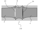
- FIG. 5 is a schematic cross-sectional view showing an example of the dissimilar material joint structure of the present invention.
- one member 2 having a different composition and the other member 4 are integrally solid-phase bonded via an insert material 6. It is characterized in that one member 2 and the insert material 6 are both deformed at the joint interface (1), and the other member 4 and the insert material 6 are both deformed at the joint interface (2). This means that at the joining interface (1) and the joining interface (2), the new surface of the insert material 6 generated by deformation and the new surface of each member are in contact with each other to form a good joining interface.
- the degree of deformation of one member 2, the other member 4, and the insert material 6 is not particularly limited as long as the bonding by contact between the new surfaces is achieved, but the bonding by contact between the new surfaces is the entire area of the surface to be joined. It is preferably achieved in. In order to achieve bonding by contact between new surfaces over the entire area of the surface to be bonded, the area of the surface to be bonded after deformation, including the portion discharged as the burr 8, should be at least twice the original area. Is preferable.
- the thickness of the intermetallic compound layer at the bonding interface (1) and the bonding interface (2) is preferably less than 1 ⁇ m. It is known that when a thick intermetallic compound layer is formed at the bonding interface, the mechanical properties of the joint such as tensile strength and fatigue strength are significantly reduced. Since the thickness of the intermetallic compound layer is less than 1 ⁇ m at both the interface (1) and the bonding interface (2), high mechanical properties can be ensured.
- the thickness of the intermetallic compound layer at the bonding interface (1) and the bonding interface (2) is preferably less than 500 nm, more preferably less than 300 nm, and more preferably 100 nm over the entire solid phase bonding interface. Most preferably less than.
- the solid phase junction interface (22, 24) has high strength and the junction has excellent mechanical properties (strength and toughness). Etc.) can be shown.
- the intermetallic compound layer does not necessarily have to be observed, and when it is not clearly observed, it indicates that the thickness is less than 500 nm.
- the solid phase bonding interface (22, 24) contains recrystallized grains. Since the structure near the bonding interface becomes fine equiaxed recrystallized grains, it is possible to obtain a bonded portion having excellent mechanical properties such as strength, toughness, and reliability.
- one member 2 is an aluminum alloy member and the other member 4 is an iron-based metal member, a copper-based metal member, or a titanium-based metal member.
- a fragile intermetallic compound layer is likely to be formed at the bonding interface between an aluminum alloy and these metals, and it is extremely difficult to obtain a joint having high mechanical properties.
- the aluminum alloy and the insert material 6 and the various metals and the insert material 6 can be solid-phase bonded by abutting each of the new surfaces, so that the formation of an intermetallic compound is suppressed. A good joint can be obtained.
- the width (diameter in the case of a cylinder) of one member 2 and / or the other member 4 is preferably 10 mm or more.
- the width of the material to be bonded becomes large, it becomes difficult to control the bonding temperature at the interface to be bonded, and it is not possible to form a homogeneous bonding interface by the conventional bonding method.
- the width is 10 mm or more (in the case of a cylinder, the diameter is 10 mm or more)
- the intermetallic compound layer is formed over the entire solid phase bonding interface (22, 24).
- the thickness is less than 1 ⁇ m.
- the width (diameter in the case of a cylinder) of one member 2 and / or the other member 4 is preferably 15 mm or more, and more preferably 20 mm or more.
- FIG. 6 shows a schematic view of a dissimilar material solid-state bonding device using the principle of linear friction welding
- FIG. 7 shows a schematic diagram of a dissimilar material solid-state bonding device using the principle of friction welding.
- the conventional linear friction joining device has a simple configuration in which a vibrating joint material is brought into contact with a fixed joint material and a joint pressure is applied.
- the insert material 6 is gripped (fixed) to the vibrating portion, and one member 2 and the other member 4 are brought into contact with each other from the left and right sides of the insert material 6.
- the mechanism is such that the insert material 6 can be slid while applying different joining pressures.
- the insert material 6 is independently fixed to a reference portion different from the one member 2 and the other member 4, and the joining pressure from the left and right can be easily controlled as long as the insert material 6 is not deformed or the like. ..
- the insert material 6 is gripped (fixed) to the rotating shaft, and one member 2 and the other member 4 are brought into contact with each other from the left and right sides of the insert material 6, and different bonding pressures are obtained.
- the mechanism is such that the insert material 6 can be rotated while applying the above.
- the insert material 6 is independently fixed to a reference portion different from one member 2 and the other member 4, but the insert material 6 needs to be slid or rotated. Absent. On the other hand, it is necessary to provide a mechanism for energizing the interface to be joined in a substantially vertical direction and raising the temperature of the interface to be joined by Joule heat generation.
- Example 1 As the material to be joined, an aluminum alloy (A7075-T6) material and a carbon steel (S45C) material were used. The dimensions of the material to be joined were both 65 mmL ⁇ 15 mmW ⁇ 3 mmT, and the 15 mmW ⁇ 3 mmT surface was defined as the surface to be joined.
- the aluminum alloy (A7075-T6) material and the carbon steel (S45C) material are a combination that does not have a temperature at which the strengths are the same.
- a pure nickel material having dimensions of 30 mmL ⁇ 15 mmW ⁇ 3 mmT was used, and the 15 mmW ⁇ 3 mmT surface was brought into contact with an aluminum alloy (A7075-T6) material and a carbon steel (S45C) material.
- the pure nickel material has a temperature at which the strength is the same as that of the aluminum alloy (A7075-T6) material and the carbon steel (S45C) material.
- a pure nickel material is formed by applying bonding pressure to the aluminum alloy material / pure nickel material interface and the carbon steel material / pure nickel material interface by the dissimilar material solid phase bonding device using the principle of linear friction bonding shown in FIG. It was slid to perform solid phase bonding of different materials.
- the bonding pressure is appropriately set in the range of 50 to 300 MPa so that the bonding pressure has different values at the aluminum alloy material / pure nickel material interface and the carbon steel material / pure nickel material interface, and the amplitude is 1 mm, the frequency is 25 Hz, and the deviation is increased.
- the bonding pressure is appropriately set in the range of 50 to 300 MPa so that the bonding pressure has different values at the aluminum alloy material / pure nickel material interface and the carbon steel material / pure nickel material interface, and the amplitude is 1 mm, the frequency is 25 Hz, and the deviation is increased.
- the bonding pressure is appropriately set in the range of 50 to 300 MPa so that the bonding pressure has different values at the aluminum alloy material / pure nickel material interface
- FIG. 9 schematically shows the temperature dependence of the strengths of aluminum alloy (A7075-T6) material, carbon steel (S45C) material, and pure nickel material.
- the temperature at which the strengths of the aluminum alloy (A7075-T6) material and the pure nickel material are the same is lower than the temperature at which the strengths of the carbon steel (S45C) material and the pure nickel material are the same.
- This relationship means that the bonding pressure applied to the aluminum alloy material / pure nickel material interface must be set to a value higher than the bonding pressure applied to the carbon steel material / pure nickel material interface.
- FIG. 10 shows an external photograph of the vicinity of the aluminum alloy material / pure nickel material interface of the dissimilar solid phase joint
- FIG. 11 shows an external photograph of the vicinity of the carbon steel material / pure nickel material interface.
- both the aluminum alloy material and the pure nickel material are deformed at the aluminum alloy material / pure nickel material interface, and the carbon steel material and the pure nickel material are both deformed at the carbon steel material / pure nickel material interface.
- the difference in the state of deformation is due to the difference in temperature dependence and thermal conductivity of the strength of the material to be joined, but the discharge of burrs and / Alternatively, the joining conditions may be set so that the new surfaces come into contact with each other in consideration of the area of the new surfaces formed by the deformation in the vicinity of the interface to be joined.
- the deviation at the aluminum alloy material / pure nickel material interface is 5 mm
- the deviation at the carbon steel material / pure nickel material interface is 4 mm.
- a cross-sectional sample (“joining pressure application direction-sliding direction” plane) was adjusted for the obtained dissimilar solid phase joint, and scanning electron microscope observation of the aluminum alloy material / pure nickel material interface and the carbon steel material / pure nickel material interface ( SEM observation) was performed.
- An SEM photograph of the aluminum alloy material / pure nickel material interface is shown in FIG. 12, and an SEM photograph of the carbon steel material / pure nickel material interface is shown in FIG. 13, respectively.
- a good bonding interface without defects is formed in the entire area of the aluminum alloy material / pure nickel material interface and the carbon steel material / pure nickel material interface.
- the film thickness is extremely thin (less than 1 ⁇ m), and there is also a region that cannot be clearly observed.
- the aluminum alloy material and the pure nickel material are both deformed at the aluminum alloy material / pure nickel material interface by the dissimilar material solid phase bonding method of the present invention, and the carbon steel material and the pure nickel material are deformed at the carbon steel material / pure nickel material interface.
- the carbon steel material and the pure nickel material are deformed at the carbon steel material / pure nickel material interface.
- a good dissimilar solid-phase joint is obtained by abutting the new surfaces.
- an extremely thin intermetallic compound layer is formed over the entire joint interface, which is defect-free. It was confirmed that the condition was realized.
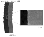
- Example 2 As the material to be joined, a titanium alloy (Ti6Al4V) material and a carbon steel (S45C) material were used. The dimensions of the material to be joined were both 65 mmL ⁇ 25 mmW ⁇ 5 mmT, and the 25 mmW ⁇ 5 mmT surface was used as the surface to be joined. As the insert material, a stainless steel (SUS304) material having dimensions of 30 mmL ⁇ 25 mmW ⁇ 5 mmT was used, and the 25 mmW ⁇ 5 mmT surface was brought into contact with the titanium alloy (Ti6Al4V) material and the carbon steel (S45C) material.
- Ti6Al4V titanium alloy
- S45C carbon steel
- Example 2 In the same manner as in Example 1, a state in which bonding pressure is applied to the titanium alloy material / stainless steel material interface and the carbon steel material / stainless steel material interface, respectively, by the dissimilar material solid phase bonding device using the principle of linear friction bonding shown in FIG. Then, the stainless steel material was slid to perform solid phase bonding of different materials.
- the bonding pressure is appropriately set in the range of 50 to 400 MPa so that the bonding pressure has different values at the titanium alloy / stainless steel interface and the carbon steel / stainless steel interface, and the amplitude is 1 mm, the frequency is 25 Hz, and the deviation is 4 mm. Or 5 mm.
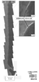
- FIG. 14 shows an SEM photograph of a cross section of the obtained titanium alloy / stainless steel joint interface.
- a good bonding interface without defects is formed in the entire area of the titanium alloy / stainless steel bonding interface.
- the film thickness is extremely thin (less than 1 ⁇ m), and there is also a region that cannot be clearly observed.
- a tensile test piece was cut out so that the obtained titanium alloy / stainless steel joint interface was at the center of the parallel portion, and a tensile test was performed.
- the size of the parallel portion of the tensile test piece is 5 mm in thickness, 6 mm in width, and 25 mm in length.
Abstract
The present invention provides dissimilar material solid phase bonding with which it is possible for a robust bonded portion comprising metal materials having different compositions to be formed efficiently. The present invention also provides a dissimilar material solid phase bonded structure having a dissimilar material solid phase bonded portion in which metal materials having different compositions have been bonded together robustly, and a dissimilar material solid phase bonding device for obtaining the dissimilar material solid phase bonded structure. The dissimilar material solid phase bonding method according to the present invention is a solid phase bonding method for bonding one member and another member, characterized in that: the one member and the other member have different compositions; the one member and the other member are brought into contact with one another by way of an insert material to form an interface (1) to be bonded, at which the one member and the insert material are in contact with one another, and an interface (2) to be bonded, at which the other member and the insert material are in contact with one another; the temperature of the interface (1) to be bonded and the interface (2) to be bonded is raised by means of frictional heat due to sliding between the one member and the other member, on the one hand, and the insert material, on the other hand, and/or by electrical heating; a bonding pressure (1) is applied substantially perpendicular to the interface (1) to be bonded; a bonding pressure (2) is applied substantially perpendicular to the interface (2) to be bonded; and the bonding pressure (1) and the bonding pressure (2) are set to different values.
Description
本発明は金属材同士を固相接合する異材固相接合方法、当該異材固相接合方法によって得られる異材固相接合構造物及び当該異材固相接合方法に用いる異材固相接合装置に関する。
The present invention relates to a dissimilar material solid phase bonding method for solid-phase bonding of metal materials, a dissimilar material solid phase bonding structure obtained by the dissimilar material solid phase bonding method, and a dissimilar material solid phase bonding device used for the dissimilar material solid phase bonding method.
鋼やアルミニウム合金等の金属材料の高強度化に伴い、接合構造物の機械的特性を決定する接合部での強度低下が深刻な問題となっている。これに対し、近年、接合中の最高到達温度が被接合材の融点に達せず、接合部における強度低下が従来の溶融溶接と比較して小さい固相接合法が注目され、急速に実用化が進んでいる。
With the increase in strength of metal materials such as steel and aluminum alloys, the decrease in strength at the joint, which determines the mechanical properties of the joint structure, has become a serious problem. On the other hand, in recent years, attention has been paid to a solid-state bonding method in which the maximum temperature reached during bonding does not reach the melting point of the material to be bonded and the decrease in strength at the joint is smaller than that of conventional melt welding, and it is rapidly put into practical use. It is progressing.
特に、回転する円柱状の被接合材を固定された被接合材に押し当てて接合する「摩擦圧接」及び被接合材を当接させた状態で往復運動させて接合する「線形摩擦接合」は、摩擦攪拌接合のように被接合材に圧入するツールを必要としないことから、鋼やチタンのような高融点・高強度金属に対しても容易に適用することができる。
In particular, "friction pressure welding" in which a rotating cylindrical material to be joined is pressed against a fixed material to be joined and "linear friction welding" in which the material to be joined is reciprocally moved in contact with the material to be joined. Since it does not require a tool for press-fitting into the material to be welded as in friction stir welding, it can be easily applied to high melting point and high strength metals such as steel and titanium.
加えて、本発明者は接合時の印加圧力で接合温度を正確に制御できる接合方法を提案し、接合温度の大幅な低温化にも成功している。例えば、特許文献1(国際公開第2017/022184号)では、2つの金属製被接合材の被接合面同士を当接させた状態で摺動させる摩擦接合方法であって、前記金属製被接合材の少なくとも一方を鉄系材とし、接合中の最高到達温度を前記鉄系材のA3点以下又はAcm点以下とすること、を特徴とする摩擦接合方法、を開示している。
In addition, the present inventor has proposed a joining method in which the joining temperature can be accurately controlled by the applied pressure at the time of joining, and has succeeded in significantly lowering the joining temperature. For example, in Patent Document 1 (International Publication No. 2017/022184), there is a friction joining method in which the surfaces to be joined of two metal materials to be joined are slid in contact with each other, and the metal joint is made of metal. Disclosed is a friction joining method characterized in that at least one of the materials is an iron-based material and the maximum temperature reached during joining is set to A 3 points or less or A cm points or less of the iron-based material.
従来の摩擦接合は摩擦熱を利用した接合方法であるが、上記特許文献1に記載の摩擦接合方法においては、金属製被接合材の塑性変形に起因する加工発熱を積極的に活用することで、低い接合温度においても良好な継手を得ることができる。
The conventional friction stir welding is a bonding method using frictional heat, but in the friction stir welding method described in Patent Document 1, the processing heat generated by the plastic deformation of the metal material to be welded is positively utilized. A good joint can be obtained even at a low joint temperature.
また、特許文献2(特開2018-122344号公報)では、一方の部材を他方の部材に当接させて被接合界面を形成する第一工程と、被接合界面に対して略垂直に圧力を印加した状態で、一方の部材と他方の部材とを同一軌跡上で繰り返し摺動させ、被接合界面からバリを排出させる第二工程と、摺動を停止して接合面を形成する第三工程と、を有し、圧力を、所望する接合温度における一方の部材及び/又は他方の部材の降伏応力以上かつ引張強度以下に設定すること、を特徴とする線形摩擦接合方法、を開示している。
Further, in Patent Document 2 (Japanese Unexamined Patent Publication No. 2018-12234), the first step of bringing one member into contact with the other member to form the interface to be joined and the pressure being applied substantially perpendicular to the interface to be joined. In the applied state, one member and the other member are repeatedly slid on the same locus to discharge burrs from the interface to be joined, and a third step of stopping sliding to form a joint surface. Discloses a linear frictional bonding method, characterized in that the pressure is set to be equal to or greater than the yield stress of one member and / or the other member and equal to or less than the tensile strength at a desired bonding temperature. ..
上記特許文献2に記載の線形摩擦接合方法においては、降伏強度と温度の関係は材料によって略一定であることを利用し、被接合界面からバリを排出させるための印加圧力によって、極めて正確に接合温度を制御することができる。
In the linear friction stir welding method described in Patent Document 2, the relationship between the yield strength and the temperature is substantially constant depending on the material, and the bonding is performed extremely accurately by the applied pressure for discharging burrs from the interface to be bonded. The temperature can be controlled.
しかしながら、各種物性が異なることに加えて接合界面に脆弱な金属間化合物を形成する場合が多い異材接合については適当な接合方法が確立されておらず、接合温度の制御及び低温化が可能な固相接合方法のメリットを十分に享受できていない。また、接合界面に金属間化合物を形成しない場合であっても、例えば、異なる組成の鋼材を接合する場合のように、固相接合中における被接合界面近傍の変形挙動が異なる場合は、固相接合によって良好な継手を得ることが困難である。
However, an appropriate bonding method has not been established for dissimilar material bonding, which often forms fragile intermetallic compounds at the bonding interface in addition to different physical characteristics, and solids capable of controlling the bonding temperature and lowering the temperature. The merits of the phase joining method have not been fully enjoyed. Further, even when an intermetallic compound is not formed at the bonding interface, if the deformation behavior in the vicinity of the interface to be bonded is different during solid phase bonding, for example, when steel materials having different compositions are bonded, the solid phase is formed. It is difficult to obtain a good joint by joining.
以上のような従来技術における問題点に鑑み、本発明の目的は、組成の異なる金属材の強固な接合部を効率的に形成することができる異材固相接合を提供することにある。また、本発明は、組成の異なる金属材が強固に接合された異材固相接合部を有する異材固相接合構造物及び当該異材固相接合構造物を得るための異材固相接合装置を提供することも目的としている。
In view of the above problems in the prior art, an object of the present invention is to provide a dissimilar solid phase joint capable of efficiently forming a strong joint portion of metal materials having different compositions. The present invention also provides a dissimilar solid phase bonding structure having a dissimilar solid phase bonding portion in which metal materials having different compositions are firmly bonded, and a dissimilar solid phase bonding device for obtaining the dissimilar solid phase bonding structure. It is also aimed at.
本発明者は上記目的を達成すべく、異材固相接合中の被接合界面近傍における被接合材の変形挙動等について鋭意研究を重ねた結果、被接合界面にインサート材を配置し、接合圧力の設定によって、インサート材と一方の被接合材の界面及びインサート材と他方の被接合材の界面において、個別の接合圧力を設定することで接合温度をそれぞれ制御し、インサート材を介して組成の異なる被接合材を強固に接合することが極めて重要であることを見出し、本発明に到達した。
In order to achieve the above object, the present inventor has conducted intensive studies on the deformation behavior of the material to be bonded in the vicinity of the interface to be bonded during solid phase bonding of dissimilar materials. Depending on the setting, the bonding temperature is controlled by setting individual bonding pressures at the interface between the insert material and one material to be bonded and the interface between the insert material and the other material to be bonded, and the composition differs through the insert material. We have found that it is extremely important to firmly join the materials to be joined, and arrived at the present invention.
即ち、本発明は、
一方の部材と他方の部材とを接合する固相接合方法であって、
前記一方の部材と前記他方の部材とは組成が異なり、
前記一方の部材と前記他方の部材とをインサート材を介して当接させ、前記一方の部材と前記インサート材とが当接した被接合界面(1)と、前記他方の部材と前記インサート材とが当接した被接合界面(2)と、を形成し、
前記一方の部材及び前記他方の部材と前記インサート材との摺動による摩擦熱、及び/又は通電加熱によって、前記被接合界面(1)及び前記被接合界面(2)を昇温し、
前記被接合界面(1)に対して略垂直に接合圧力(1)を印加し、
前記被接合界面(2)に対して略垂直に接合圧力(2)を印加し、
前記接合圧力(1)と前記接合圧力(2)を異なる値に設定すること、
を特徴とする異材固相接合方法、を提供する。 That is, the present invention
A solid-phase joining method for joining one member and the other member.
The composition of the one member and the other member are different.
The interface (1) to be joined, in which one member and the other member are brought into contact with each other via an insert material, and the other member and the insert material are in contact with each other, and the other member and the insert material. Formed the interface (2) to be joined, which was in contact with
The temperature of the interface to be joined (1) and the interface to be joined (2) is raised by frictional heat due to sliding of the one member and the other member and the insert material, and / or energization heating.
A bonding pressure (1) is applied substantially perpendicular to the interface (1) to be bonded.
A bonding pressure (2) is applied substantially perpendicular to the interface (2) to be bonded.
Setting the bonding pressure (1) and the bonding pressure (2) to different values,
Provided is a method for solid-phase bonding of dissimilar materials, which is characterized by the above.
本発明の異材固相接合方法では、組成が異なる一方の部材と他方の部材とを接合するが、例えば、鋼部材とチタン合金部材のように主元素が異なる場合だけでなく、異なる組成の鋼部材のように、主元素が同一で添加元素が異なる組合せにも適用することができる。
In the dissimilar solid phase bonding method of the present invention, one member having a different composition and the other member are bonded, but not only when the main elements are different, such as a steel member and a titanium alloy member, but also steels having different compositions. It can be applied to a combination having the same main element but different additive elements, such as a member.
本発明の異材固相接合方法は、組成の異なる部材を、インサート材を介して接合する方法であり、インサート材が一方の部材及び他方の部材と「略同一の強度となる温度」を有することが好ましい。金属材料の強度は温度に依存するところ、インサート材と一方の部材の強度、及びインサート材と他方の部材の強度が略同一となる温度において固相接合を施すことによって、被接合界面(1)及び被接合界面(2)でインサート材と各部材を変形させることで、インサート材と各部材の被接合面に新生面が形成され、当該新生面同士が当接することによる良好な接合部を得ることができる。なお、略同一の強度とは、完全に強度を同一とすることを意味するものではなく、被接合界面における新生面の形成が同程度に進行する強度範囲であればよい。よって、「略同一の強度」は、数十MPa程度の差は許容される。
The dissimilar material solid phase joining method of the present invention is a method of joining members having different compositions via an insert material, and the insert material has "a temperature at which the strength becomes substantially the same" as that of one member and the other member. Is preferable. Where the strength of the metal material depends on the temperature, the interface to be bonded (1) is formed by performing solid phase bonding at a temperature at which the strength of the insert material and one member and the strength of the insert material and the other member are substantially the same. By deforming the insert material and each member at the interface (2) to be joined, a new surface is formed on the surface to be joined between the insert material and each member, and a good joint can be obtained by contacting the new surfaces with each other. it can. It should be noted that substantially the same strength does not mean that the strengths are completely the same, and it may be a strength range in which the formation of the new surface at the interface to be joined proceeds to the same extent. Therefore, a difference of about several tens of MPa is allowed for "substantially the same strength".
本発明の異材固相接合方法では接合温度を正確に制御する必要があるが、被接合界面に対して略垂直に印加される接合荷重を適当に設定することで、当該目的を達成することができる。例えば、線形摩擦接合の場合では、線形摩擦接合の印加圧力を増加させると当該摩擦熱は増加するが、軟化した材料はバリとなって連続的に排出されるため、軟化した材料に印加される圧力(バリを排出する力)によって「接合温度」が決定される。つまり、印加圧力を高く設定した場合、より高い強度(降伏強度が高い状態)の被接合材をバリとして排出することができる。ここで、「より降伏強度が高い状態」とは、「より低温の状態」を意味していることから、印加圧力の増加によって「接合温度」が低下することになる。降伏強度と温度の関係は材料によって略一定であることから、極めて正確に接合温度を制御することができる。
In the dissimilar solid phase bonding method of the present invention, it is necessary to accurately control the bonding temperature, but the object can be achieved by appropriately setting the bonding load applied substantially perpendicular to the interface to be bonded. it can. For example, in the case of linear friction stir welding, increasing the applied pressure of linear friction stir welding increases the frictional heat, but the softened material becomes burrs and is continuously discharged, so it is applied to the softened material. The "bonding temperature" is determined by the pressure (force to discharge burrs). That is, when the applied pressure is set high, the material to be joined with higher strength (state in which the yield strength is high) can be discharged as burrs. Here, since the "state of higher yield strength" means the "state of lower temperature", the "joining temperature" is lowered by the increase of the applied pressure. Since the relationship between the yield strength and the temperature is substantially constant depending on the material, the junction temperature can be controlled extremely accurately.
通電加熱によって被接合界面(1)及び被接合界面(2)を昇温する場合であっても、接合圧力による接合温度の制御は同様に達成することができ、印加される接合圧力によって軟化した材料はバリとなって連続的に排出されるため、軟化した材料に印加される圧力(バリを排出する力)によって「接合温度」が決定される。なお、通電加熱を用いる場合、金属の電気抵抗に影響されるため、必ずしも同じ温度でなくてもよい。
Even when the temperature of the interface to be bonded (1) and the interface to be bonded (2) is raised by energization heating, control of the bonding temperature by the bonding pressure can be similarly achieved, and the bonding temperature is softened by the applied bonding pressure. Since the material becomes burrs and is continuously discharged, the "bonding temperature" is determined by the pressure (force to discharge burrs) applied to the softened material. When energization heating is used, the temperature does not necessarily have to be the same because it is affected by the electrical resistance of the metal.
ここで、本発明の効果を損なわない限り被接合界面近傍を昇温する方法は特に限定されず、従来公知の種々の昇温方法(接合方法)を用いることができる。例えば、回転する円柱状の被接合材を固定された被接合材に押し当てて接合する「摩擦圧接」及び被接合材を当接させた状態で往復運動させて接合する「線形摩擦接合」に加えて、通電加熱、高周波加熱、レーザ加熱及び火炎加熱等あるいはこれらの組合せを用いてもよい。また、一方の部材と他方の部材とをインサート材を介して当接させた状態で、インサート材を移動(摺動)させてもよく、一方の部材及び他方の部材を移動(摺動)させてもよい。更に、摩擦圧接を用いて一方の部材と他方の部材とを回転させる場合、当該一方の部材と当該他方の部材を逆方向に回転させてもよい。
Here, the method for raising the temperature in the vicinity of the interface to be joined is not particularly limited as long as the effect of the present invention is not impaired, and various conventionally known raising methods (bonding methods) can be used. For example, "friction pressure welding" in which a rotating cylindrical material to be joined is pressed against a fixed material to be joined, and "linear friction welding" in which the material to be joined is reciprocally moved in contact with the material to be joined. In addition, energization heating, high frequency heating, laser heating, flame heating, or a combination thereof may be used. Further, the insert material may be moved (sliding) in a state where one member and the other member are brought into contact with each other via the insert material, and one member and the other member may be moved (sliding). You may. Further, when the one member and the other member are rotated by friction welding, the one member and the other member may be rotated in opposite directions.
また、本発明の異材固相接合方法においては、前記インサート材と前記一方の部材とが略同一の強度となる温度(1)が存在し、前記インサート材と前記他方の部材とが略同一の強度となる温度(2)が存在し、前記温度(1)と前記温度(2)とが異なる値であること、が好ましい。一方の部材と他方の部材の組成が異なる場合、インサート材と各部材の強度が略同一となる温度は異なることから、接合圧力(1)と接合圧力(2)は異なる値に設定することになる。ここで、接合温度を温度(1)及び/又は温度(2)とすることが好ましいが、必ずしも同一の値とする必要はなく、被接合界面にインサート材と被接合材の新生面が形成されれば、接合を達成することができる。また、接合温度に及ぼす被接合材とインサート材の大きさの影響についても留意することが好ましい。
Further, in the dissimilar material solid phase bonding method of the present invention, there is a temperature (1) at which the insert material and the one member have substantially the same strength, and the insert material and the other member are substantially the same. It is preferable that there is a temperature (2) that becomes an intensity, and that the temperature (1) and the temperature (2) are different values. When the composition of one member and the other member are different, the temperature at which the strengths of the insert material and each member are substantially the same is different, so the joining pressure (1) and the joining pressure (2) are set to different values. Become. Here, the joining temperature is preferably set to temperature (1) and / or temperature (2), but it is not always necessary to set the joining temperature to the same value, and a new surface of the insert material and the joined material is formed at the interface to be joined. For example, joining can be achieved. It is also preferable to pay attention to the influence of the sizes of the material to be joined and the insert material on the joining temperature.
本発明の異材固相接合方法の最大の特徴は、一方の部材とインサート材とが当接した被接合界面(1)及び、他方の部材とインサート材とが当接した被接合界面(2)のそれぞれに対して略垂直に接合圧力(接合圧力(1)及び接合圧力(2))を印加し、接合圧力(1)と接合圧力(2)を異なる値に設定することにある。接合圧力(1)と接合圧力(2)を異なる圧力に設定することで、各被接合界面において新生面同士の接合に適した接合温度をそれぞれ実現することができる。
The greatest feature of the dissimilar solid phase bonding method of the present invention is the interface to be bonded (1) where one member and the insert material are in contact with each other and the interface to be bonded (2) where the other member and the insert material are in contact with each other. The joining pressure (joining pressure (1) and joining pressure (2)) is applied substantially perpendicularly to each of the above, and the joining pressure (1) and the joining pressure (2) are set to different values. By setting the bonding pressure (1) and the bonding pressure (2) to different pressures, it is possible to realize a bonding temperature suitable for bonding the new surfaces at each interface to be bonded.
また、本発明の異材固相接合方法においては、前記接合圧力(1)を前記温度(1)における前記インサート材及び前記一方の部材の降伏応力以上引張強度以下の値とし、前記接合圧力(2)を前記温度(2)における前記インサート材及び前記他方の部材の降伏強度以上引張強度以下の値とすること、が好ましい。固相接合時の圧力を被接合材の降伏応力以上とすることで被接合界面からのバリの排出が開始され、引張強度までの間で当該圧力を増加させると、バリの排出が加速されることになる。降伏応力と同様に、特定の温度における引張強度も被接合材によって略一定であることから、設定した圧力に対応する接合温度を実現することができる。
Further, in the dissimilar material solid phase bonding method of the present invention, the bonding pressure (1) is set to a value equal to or greater than the yield stress of the insert material and the one member at the temperature (1) and equal to or less than the tensile strength, and the bonding pressure (2). ) Is preferably a value equal to or more than the yield strength of the insert material and the other member at the temperature (2) and not more than the tensile strength. When the pressure at the time of solid phase bonding is equal to or higher than the yield stress of the material to be bonded, the discharge of burrs from the interface to be bonded is started, and when the pressure is increased up to the tensile strength, the discharge of burrs is accelerated. It will be. Similar to the yield stress, the tensile strength at a specific temperature is substantially constant depending on the material to be bonded, so that the bonding temperature corresponding to the set pressure can be realized.
また、本発明の異材固相接合においては、一方の部材、他方の部材及びインサート材の組合せによって、基本的に接合温度が決定されるが、被接合材として鉄系金属を用いる場合、接合温度は当該鉄系金属のA1点以下とすることが好ましい。鉄系金属では相変態によって脆いマルテンサイトが形成し、接合が困難な場合及び接合部が脆化してしまう場合が存在する。これに対し、接合温度をA1点以下とすることで、相変態が生じないことから、脆いマルテンサイトの形成を完全に抑制することができる。また、被接合材としてチタン合金を用いる場合は、接合温度を当該チタン合金のβトランザス温度以下とすることが好ましい。接合温度をβトランザス温度以下とすることで、等軸状の微細な再結晶粒組織からなる良好な接合部を得ることができる。更に、被接合材としてニッケル基超合金を用いる場合は、継手の強度低下を抑制することができる。
Further, in the solid-phase bonding of different materials of the present invention, the bonding temperature is basically determined by the combination of one member, the other member and the insert material, but when an iron-based metal is used as the material to be bonded, the bonding temperature is determined. Is preferably A 1 point or less of the iron-based metal. In iron-based metals, brittle martensite is formed by phase transformation, and there are cases where joining is difficult and cases where the joining portion becomes brittle. On the other hand, when the bonding temperature is set to A 1 point or less, phase transformation does not occur, so that the formation of brittle martensite can be completely suppressed. When a titanium alloy is used as the material to be bonded, the bonding temperature is preferably set to be equal to or lower than the β transus temperature of the titanium alloy. By setting the bonding temperature to β-transus temperature or lower, a good bonding portion composed of equiaxed fine recrystallized grain structures can be obtained. Further, when a nickel-based superalloy is used as the material to be joined, it is possible to suppress a decrease in the strength of the joint.
また、本発明の異材固相接合においては、前記一方の部材及び/又は前記他方の部材に外部冷却及び/又は外部加熱を施すことで、前記接合温度を調節してもよい。外部冷却及び/又は外部加熱を用いることで、被接合界面近傍における一方の部材と他方の部材の変形及び/又はバリの排出を制御することができる。
Further, in the solid phase bonding of different materials of the present invention, the bonding temperature may be adjusted by applying external cooling and / or external heating to the one member and / or the other member. By using external cooling and / or external heating, it is possible to control the deformation of one member and / or the discharge of burrs in the vicinity of the interface to be joined.
また、本発明の異材固相接合方法においては、前記一方の部材をアルミニウム合金部材とし、前記他方の部材を鉄系金属部材、銅系金属部材又はチタン系金属部材とすること、が好ましい。アルミニウム合金とこれらの金属部材の接合界面には脆弱な金属間化合物層が形成されやすく、高い機械的性質を有する継手を得ることは極めて困難である。また、被接合材に強度差が存在する場合、強度の弱い被接合材が一方的に変形し、強度の強い被接合材の新生面を形成することが困難である。これに対し、本発明の異材固相接合方法ではアルミニウム合金とインサート材、及び鉄系金属(銅系金属、チタン系金属)とインサート材を、それぞれ新生面同士の当接によって固相接合できることから、新生面同士の接合が達成されるだけでなく、金属間化合物の形成が抑制された良好な継手を得ることができる。なお、本発明において鉄系金属とは、組成において鉄を主とする金属を意味し、例えば、種々の鋼や鋳鉄等が含まれる。また、本発明において銅系金属とは、組成において銅を主とする金属を意味し、チタン系金属とは、組成においてチタンを主とする金属を意味する。
Further, in the dissimilar material solid phase bonding method of the present invention, it is preferable that one of the members is an aluminum alloy member and the other member is an iron-based metal member, a copper-based metal member or a titanium-based metal member. A fragile intermetallic compound layer is likely to be formed at the bonding interface between the aluminum alloy and these metal members, and it is extremely difficult to obtain a joint having high mechanical properties. Further, when there is a difference in strength between the materials to be joined, the material to be joined with weak strength is unilaterally deformed, and it is difficult to form a new surface of the material to be joined with high strength. On the other hand, in the dissimilar solid phase bonding method of the present invention, the aluminum alloy and the insert material, and the iron-based metal (copper-based metal, titanium-based metal) and the insert material can be solid-phase bonded by abutting between the new surfaces. Not only can the new surfaces be joined together, but a good joint in which the formation of intermetallic compounds is suppressed can be obtained. In the present invention, the iron-based metal means a metal mainly composed of iron in its composition, and includes, for example, various steels and cast iron. Further, in the present invention, the copper-based metal means a metal mainly composed of copper in the composition, and the titanium-based metal means a metal mainly composed of titanium in the composition.
また、本発明は、
一方の部材と他方の部材がインサート材を介して一体となった固相接合部を有し、
前記一方の部材と前記他方の部材の少なくとも一方が、前記インサート材とは異なる組成を有し、
前記一方の部材と前記インサート材とが当接した接合界面(1)において、前記一方の部材と前記インサート材とが共に変形し、
前記他方の部材と前記インサート材とが当接した接合界面(2)において、前記他方の部材と前記インサート材とが共に変形していること、
を特徴とする異材固相接合構造物、も提供する。 In addition, the present invention
It has a solid phase joint in which one member and the other member are integrated via an insert material.
At least one of the one member and the other member has a composition different from that of the insert material.
At the joining interface (1) where the one member and the insert material are in contact with each other, both the one member and the insert material are deformed.
At the joining interface (2) where the other member and the insert material are in contact with each other, both the other member and the insert material are deformed.
Also provided is a dissimilar solid phase bonding structure.
本発明の異材固相接合構造物においては、一方の部材とインサート材とが当接した接合界面(1)において、一方の部材とインサート材とが共に変形し、他方の部材とインサート材とが当接した接合界面(2)において、他方の部材とインサート材とが共に変形している。これは、接合界面(1)及び接合界面(2)において、変形によって生成するインサート材の新生面と各部材の新生面が当接し、良好な接合界面が形成されていることを意味している。ここで、「変形」にはバリの形成や塑性変形等が含まれるが、本発明における「変形」は、接合界面において新生面の形成を伴うものを意味する。
In the dissimilar solid phase bonding structure of the present invention, at the bonding interface (1) where one member and the insert material are in contact with each other, both the one member and the insert material are deformed, and the other member and the insert material are separated from each other. At the abutting interface (2), the other member and the insert material are both deformed. This means that at the joint interface (1) and the joint interface (2), the new surface of the insert material generated by deformation and the new surface of each member are in contact with each other to form a good joint interface. Here, the "deformation" includes the formation of burrs, plastic deformation, and the like, but the "deformation" in the present invention means the one accompanied by the formation of a new surface at the joint interface.
一方の部材、他方の部材及びインサート材の変形の程度は、新生面同士の当接による接合が達成される限りにおいて特に限定されないが、新生面同士の当接による接合が被接合面の全域において達成されることが好ましい。新生面同士の当接による接合を被接合面の全域において達成するためには、バリとして排出される部分を含めて、変形後の被接合面の面積が元の面積の2倍以上となるようにすることが好ましい。
The degree of deformation of one member, the other member, and the insert material is not particularly limited as long as the bonding by contact between the new surfaces is achieved, but the bonding by contact between the new surfaces is achieved over the entire surface to be joined. Is preferable. In order to achieve bonding by contact between new surfaces over the entire area of the surface to be bonded, the area of the surface to be bonded after deformation, including the portion discharged as burrs, should be at least twice the original area. It is preferable to do so.
また、本発明の異材固相接合構造物においては、前記一方の部材がアルミニウム合金部材であり、前記他方の部材が鉄系金属部材、銅系金属部材又はチタン系部材であること、が好ましい。アルミニウム合金とこれらの金属の接合界面には脆弱な金属間化合物層が形成されやすく、高い機械的性質を有する継手を得ることは極めて困難である。これに対し、本発明の異材固相接合方法ではアルミニウム合金とインサート材、及び各種金属とインサート材を、それぞれ新生面同士の当接によって固相接合できることから、金属間化合物の形成が抑制された良好な継手を得ることができる。
Further, in the dissimilar solid phase bonding structure of the present invention, it is preferable that one of the members is an aluminum alloy member and the other member is an iron-based metal member, a copper-based metal member or a titanium-based member. A fragile intermetallic compound layer is likely to be formed at the bonding interface between an aluminum alloy and these metals, and it is extremely difficult to obtain a joint having high mechanical properties. On the other hand, in the dissimilar solid phase bonding method of the present invention, the aluminum alloy and the insert material, and various metals and the insert material can be solid-phase bonded by abutting each of the new surfaces, so that the formation of the intermetallic compound is suppressed. Can be obtained.
また、本発明の異材固相接合構造物においては、前記接合界面(1)及び前記接合界面(2)における金属間化合物層の厚さが1μm未満であること、が好ましい。接合界面に厚い金属間化合物層が形成される場合は、引張強度や靭性等の継手の機械的性質が著しく低下することが知られているが、本発明の異材固相接合構造物においては、接合界面(1)及び接合界面(2)の両方において、金属間化合物層の厚さが1μm未満となっていることから、高い機械的性質を担保することができる。
Further, in the dissimilar solid phase bonding structure of the present invention, it is preferable that the thickness of the intermetallic compound layer at the bonding interface (1) and the bonding interface (2) is less than 1 μm. It is known that when a thick intermetallic compound layer is formed at the bonding interface, the mechanical properties of the joint such as tensile strength and toughness are significantly reduced. Since the thickness of the intermetallic compound layer is less than 1 μm at both the bonding interface (1) and the bonding interface (2), high mechanical properties can be ensured.
ここで、接合界面(1)及び接合界面(2)における金属間化合物層の厚さは、固相接合界面の全域において500nm未満となっていることが好ましく、300nm未満となっていることがより好ましく、100nm未満となっていることが最も好ましい。固相接合界面の全域において薄い金属間化合物層が形成する結果、固相接合界面は高い強度を有し、接合部は優れた機械的性質(強度及び靭性等)を示すことができる。
Here, the thickness of the intermetallic compound layer at the bonding interface (1) and the bonding interface (2) is preferably less than 500 nm over the entire solid phase bonding interface, and more preferably less than 300 nm. It is preferably less than 100 nm, most preferably less than 100 nm. As a result of the formation of a thin intermetallic compound layer over the entire solid-phase bonding interface, the solid-phase bonding interface has high strength, and the bonded portion can exhibit excellent mechanical properties (strength, toughness, etc.).
また、本発明の異材接合構造物においては、固相接合界面に再結晶粒が含まれることが好ましい。接合界面近傍の組織が微細等軸の再結晶粒となることで、強度、靱性、信頼性等の機械的特性に優れた接合部とすることができる。
Further, in the dissimilar material bonding structure of the present invention, it is preferable that the solid phase bonding interface contains recrystallized grains. Since the structure near the bonding interface becomes fine equiaxed recrystallized grains, it is possible to obtain a bonded portion having excellent mechanical properties such as strength, toughness, and reliability.
本発明の異材固相接合構造物は、本発明の異材固相接合方法を用いて好適に得ることができる。
The dissimilar solid phase bonding structure of the present invention can be suitably obtained by using the dissimilar solid phase bonding method of the present invention.
更に、本発明は、
一方の部材と他方の部材とを接合する固相接合装置であって、
前記一方の部材と前記他方の部材とをインサート材を介して当接させ、前記一方の部材と前記インサート材とが当接した被接合界面(1)と、前記他方の部材と前記インサート材とが当接した被接合界面(2)と、を形成する把持機構と、
前記一方の部材と前記他方の部材との間で前記インサート材を直線移動又は回転させる摺動機構、及び/又は前記インサート材に当接した状態で前記一方の部材及び前記他方の部材を直線移動又は回転させる摺動機構、及び/又は前記被接合界面(1)及び前記被接合界面(2)を通電加熱する通電加熱機構と、
前記被接合界面(1)に対して略垂直に接合圧力(1)を印加し、前記被接合界面(2)に対して略垂直に接合圧力(2)を印加し、前記接合圧力(1)と前記接合圧力(2)を異なる値に設定することが可能な押圧機構と、を具備すること、
を特徴とする異材固相接合装置、も提供する。 Furthermore, the present invention
A solid-phase joining device that joins one member and the other member.
The interface (1) to be joined, in which one member and the other member are brought into contact with each other via an insert material, and the other member and the insert material are in contact with each other, and the other member and the insert material. A gripping mechanism that forms the interface (2) to be joined with which
A sliding mechanism that linearly moves or rotates the insert material between the one member and the other member, and / or linearly moves the one member and the other member while in contact with the insert material. Or a sliding mechanism that rotates, and / or an energization heating mechanism that energizes and heats the interface to be joined (1) and the interface to be joined (2).
The bonding pressure (1) is applied substantially perpendicular to the interface to be bonded (1), the bonding pressure (2) is applied substantially perpendicular to the interface to be bonded (2), and the bonding pressure (1) is applied. And a pressing mechanism capable of setting the bonding pressure (2) to different values.
Also provided is a dissimilar solid phase bonding apparatus.
本発明の異材固相接合装置は、本発明の異材固相接合方法によって本発明の異材固相接合構造物を得るために、好適に用いることができる装置である。本発明の異材固相接合装置においては、「把持機構」、「摺動機構及び/又は通電加熱機構」及び「押圧機構」が必須であるが、押圧機構において接合圧力(1)と接合圧力(2)を異なる値に設定できることを最大の特徴としている。
The dissimilar material solid phase bonding device of the present invention is a device that can be suitably used for obtaining the dissimilar material solid phase bonding structure of the present invention by the dissimilar material solid phase bonding method of the present invention. In the dissimilar solid phase bonding device of the present invention, a "grasping mechanism", a "sliding mechanism and / or an energizing heating mechanism" and a "pressing mechanism" are indispensable. The biggest feature is that 2) can be set to different values.
接合圧力(1)と接合圧力(2)を異なる値に設定する具体的な方法は、本発明の効果を損なわない限りにおいて特に限定されないが、例えば、インサート材を被接合材(一方の部材及び他方の部材)とは異なる基準部位に固定し、独立に固定されたインサート材の両面から異なる接合圧力を印加すればよい。また、インサート材を固定した部位に別途押圧機構を設けてもよい。
The specific method for setting the joining pressure (1) and the joining pressure (2) to different values is not particularly limited as long as the effect of the present invention is not impaired. It may be fixed at a reference site different from the other member), and different joining pressures may be applied from both sides of the insert material fixed independently. Further, a pressing mechanism may be separately provided at the portion where the insert material is fixed.
より具体的には、例えば、従来一般的な線形摩擦接合装置においては、一方の部材を固定し、当該一方の部材に他方の部材を当接させ、接合圧力を印加すると共に他方の部材を加振する単純な構造となっている。これに対し、本発明の異材固相接合装置においては、例えば、インサート材を加振部に連結し、インサート材の左右から異なる接合圧力を印加すればよい。
More specifically, for example, in a conventional general linear friction stir welding device, one member is fixed, the other member is brought into contact with the one member, a bonding pressure is applied, and the other member is applied. It has a simple structure to shake. On the other hand, in the dissimilar material solid phase bonding apparatus of the present invention, for example, the insert material may be connected to the vibrating portion and different bonding pressures may be applied from the left and right sides of the insert material.
また、本発明の異材固相接合装置においては、
前記インサート材と前記一方の部材とが略同一の強度となる温度(1)が存在し、前記インサート材と前記他方の部材とが略同一の強度となる温度(2)が存在する場合において、
前記温度(1)における前記インサート材及び前記一方の部材の降伏応力以上引張強度以下の値を、前記接合圧力(1)として前記被接合界面(1)に印加することができ、
前記温度(2)における前記インサート材及び前記他方の部材の降伏強度以上引張強度以下の値を、前記接合圧力(2)として前記被接合界面(2)に印加することができること、
が好ましい。 Further, in the dissimilar material solid phase bonding apparatus of the present invention,
When there is a temperature (1) at which the insert material and the one member have substantially the same strength, and there is a temperature (2) at which the insert material and the other member have substantially the same strength.
A value equal to or greater than the yield stress of the insert material and the one member at the temperature (1) and equal to or less than the tensile strength can be applied to the interface to be joined (1) as the bonding pressure (1).
A value of yield strength or more and tensile strength or less of the insert material and the other member at the temperature (2) can be applied to the interface to be joined (2) as the bonding pressure (2).
Is preferable.
固相接合時の圧力を被接合材の降伏応力以上とすることで被接合界面からのバリの排出が開始され、引張強度までの間で当該圧力を増加させると、バリの排出が加速されることになる。降伏応力と同様に、特定の温度における引張強度も被接合材によって略一定であることから、設定した圧力に対応する接合温度を実現することができる。本発明の効果を損なわない限りにおいて、接合圧力の印加方法は特に限定されず、従来公知の種々の方法を用いることができる。
When the pressure at the time of solid phase bonding is equal to or higher than the yield stress of the material to be bonded, the discharge of burrs from the interface to be bonded is started, and when the pressure is increased up to the tensile strength, the discharge of burrs is accelerated. It will be. Similar to the yield stress, the tensile strength at a specific temperature is substantially constant depending on the material to be bonded, so that the bonding temperature corresponding to the set pressure can be realized. As long as the effect of the present invention is not impaired, the method of applying the bonding pressure is not particularly limited, and various conventionally known methods can be used.
更に、本発明の異材固相接合装置においては、接合中の被接合界面(1)近傍及び被接合界面(2)近傍の温度、及び接合荷重を計測し、得られた実測温度と接合条件から予測される接合温度を比較し、実測温度が予測接合温度よりも高い場合は接合荷重を増加させ、実測温度が接合温度よりも低い場合は接合荷重を低下させること、が好ましい。当該フィードバック機構を有することで、より正確に接合温度を制御することができる。
Further, in the dissimilar solid phase bonding apparatus of the present invention, the temperatures in the vicinity of the interface to be bonded (1) and the interface to be bonded (2) during bonding and the bonding load are measured, and the measured temperature and the bonding conditions obtained are used. It is preferable to compare the predicted joining temperatures and increase the joining load when the measured temperature is higher than the predicted joining temperature and decrease the joining load when the measured temperature is lower than the joining temperature. By having the feedback mechanism, the junction temperature can be controlled more accurately.
本発明によれば、組成の異なる金属材の強固な接合部を効率的に形成することができる異材固相接合を提供することができる。また、本発明によれば、組成の異なる金属材が強固に接合された異材固相接合部を有する異材固相接合構造物及び当該異材固相接合構造物を得るための異材固相接合装置を提供することもできる。
According to the present invention, it is possible to provide a dissimilar material solid phase joint capable of efficiently forming a strong joint portion of metal materials having different compositions. Further, according to the present invention, a dissimilar solid phase bonding structure having a dissimilar solid phase bonding portion in which metal materials having different compositions are firmly bonded and a dissimilar solid phase bonding device for obtaining the dissimilar solid phase bonding structure are provided. It can also be provided.
以下、図面を参照しながら本発明の異材固相接合方法、異材固相接合構造物及び異材固相接合装置の代表的な実施形態について、主として線形摩擦接合を代表例として詳細に説明するが、本発明はこれらのみに限定されるものではない。なお、以下の説明では、同一または相当部分には同一符号を付し、重複する説明は省略する場合がある。また、図面は、本発明を概念的に説明するためのものであるから、表された各構成要素の寸法やそれらの比は実際のものとは異なる場合もある。
Hereinafter, a typical embodiment of the dissimilar material solid phase bonding method, the dissimilar material solid phase bonding structure, and the dissimilar material solid phase bonding apparatus of the present invention will be described in detail with reference to the drawings, mainly using linear friction bonding as a representative example. The present invention is not limited to these. In the following description, the same or corresponding parts may be designated by the same reference numerals, and duplicate description may be omitted. Moreover, since the drawings are for conceptually explaining the present invention, the dimensions of each component represented and their ratios may differ from the actual ones.
(1)異材固相接合方法
図1に一般的な線形摩擦接合中の状況を示す模式図を示す。線形摩擦接合は被接合材同士を線形運動で擦りあわせた際に生じる摩擦熱を主な熱源とする固相接合である。従来の線形摩擦接合においては、昇温によって軟化した材料を被接合界面からバリとして排出することで、被接合界面に形成していた酸化被膜を除去し、新生面同士を当接させることで接合部が得られるとされている。 (1) Dissimilar material solid phase bonding method FIG. 1 shows a schematic diagram showing a general situation during linear friction bonding. Linear friction stir welding is a solid phase welding in which the frictional heat generated when the materials to be welded are rubbed against each other by linear motion is the main heat source. In the conventional linear friction stir welding, the material softened by the temperature rise is discharged as burrs from the interface to be welded to remove the oxide film formed at the interface to be welded, and the new surfaces are brought into contact with each other to bring the joints into contact with each other. Is said to be obtained.
図1に一般的な線形摩擦接合中の状況を示す模式図を示す。線形摩擦接合は被接合材同士を線形運動で擦りあわせた際に生じる摩擦熱を主な熱源とする固相接合である。従来の線形摩擦接合においては、昇温によって軟化した材料を被接合界面からバリとして排出することで、被接合界面に形成していた酸化被膜を除去し、新生面同士を当接させることで接合部が得られるとされている。 (1) Dissimilar material solid phase bonding method FIG. 1 shows a schematic diagram showing a general situation during linear friction bonding. Linear friction stir welding is a solid phase welding in which the frictional heat generated when the materials to be welded are rubbed against each other by linear motion is the main heat source. In the conventional linear friction stir welding, the material softened by the temperature rise is discharged as burrs from the interface to be welded to remove the oxide film formed at the interface to be welded, and the new surfaces are brought into contact with each other to bring the joints into contact with each other. Is said to be obtained.
本発明の異材固相接合方法の接合中の状況及び接合温度の関係を模式的に図2に示す。本発明の異材固相接合方法においては、組成が異なる一方の部材2と他方の部材4とをインサート材6を介して当接させ、一方の部材2とインサート材6とが当接した被接合界面(1)と、他方の部材4とインサート材6とが当接した被接合界面(2)と、が形成されている。
FIG. 2 schematically shows the relationship between the state during bonding and the bonding temperature of the dissimilar solid phase bonding method of the present invention. In the dissimilar material solid phase bonding method of the present invention, one member 2 and the other member 4 having different compositions are brought into contact with each other via the insert material 6, and one member 2 and the insert material 6 are brought into contact with each other. An interface (1) and an interface (2) to be joined in which the other member 4 and the insert material 6 are in contact with each other are formed.
当該状態において、線形摩擦接合の原理を用いる場合は、インサート材6を上下に繰り返し摺動させることによって、被接合界面(1)及び被接合界面(2)に摩擦熱を発生させる。なお、摩擦圧接の原理を用いる場合はインサート材6を回転させて摩擦熱を発生させ、通電加熱の原理を用いる場合は被接合界面(1)及び被接合界面(2)に略垂直方向に通電し、ジュール熱を発生させればよい。
In this state, when the principle of linear friction stir welding is used, frictional heat is generated at the interface to be welded (1) and the interface to be welded (2) by repeatedly sliding the insert material 6 up and down. When the principle of friction welding is used, the insert material 6 is rotated to generate frictional heat, and when the principle of energization heating is used, the interface (1) and the interface (2) to be joined are energized in a substantially vertical direction. Then, Joule heat may be generated.
ここで、被接合界面(1)に対して略垂直に接合圧力(1)を印加し、被接合界面(2)に対して略垂直に接合圧力(2)を印加し、接合圧力(1)と接合圧力(2)を異なる値に設定する。図2の上側に示されたグラフは、一方の部材2、他方の部材4及びインサート材6の強度の温度依存性を模式的に示したものである。一方の部材2及び他方の部材4が図2に示すような強度の温度依存性を有する場合、一方の部材2及び他方の部材4の強度が同一となる温度は存在しないことから、被接合界面において一方の部材2及び他方の部材4を同程度変形させることはできない。これに対し、図2に示すような強度の温度依存性を有するインサート材6を用いることで、被接合界面(1)及び被接合界面(2)において、新生面同士が当接することによる良好な継手を得ることができる。
Here, the bonding pressure (1) is applied substantially perpendicular to the interface to be bonded (1), the bonding pressure (2) is applied substantially perpendicular to the interface to be bonded (2), and the bonding pressure (1) is applied. And the joint pressure (2) are set to different values. The graph shown on the upper side of FIG. 2 schematically shows the temperature dependence of the strength of one member 2, the other member 4, and the insert material 6. When one member 2 and the other member 4 have a temperature dependence of the strength as shown in FIG. 2, since there is no temperature at which the strengths of the one member 2 and the other member 4 are the same, the interface to be joined is formed. One member 2 and the other member 4 cannot be deformed to the same extent. On the other hand, by using the insert material 6 having a strength temperature dependence as shown in FIG. 2, a good joint due to the new surfaces coming into contact with each other at the interface to be joined (1) and the interface to be joined (2). Can be obtained.
より具体的には、インサート材6の強度の温度依存性を示す線は、一方の部材2の強度の温度依存性を示す線及び他方の部材4の強度の温度依存性を示す線と共に交点を有している。ここで、被接合界面(1)においては一方の部材2とインサート材6との交点に対応する接合圧力(1)を、被接合界面(2)においては他方の部材4とインサート材6の交点に対応する接合圧力(2)を設定すればよい。
More specifically, the line showing the temperature dependence of the strength of the insert material 6 intersects with the line showing the temperature dependence of the strength of one member 2 and the line showing the temperature dependence of the strength of the other member 4. Have. Here, at the interface to be joined (1), the joining pressure (1) corresponding to the intersection of one member 2 and the insert material 6 is applied, and at the interface to be joined (2), the intersection of the other member 4 and the insert material 6 is applied. The joining pressure (2) corresponding to the above may be set.
なお、図2に示す強度の温度依存性の関係は一例であり、例えば、図3に示すような強度の温度依存性を有する被接合材及びインサート材6の組合せを用いてもよい。インサート材6は一方の部材2及び他方の部材4と「交点」を有していればよく、従来公知の種々の金属材から選定することができる。なお、この限りではないが、一般的にはbcc結晶構造を有する金属は強度の温度依存性が小さいものが多く、fcc結晶構造を有する金属同士を接合する際のインサート材の候補となる。一方で、bcc結晶構造を有する金属同士を接合する場合は、fcc結晶構造を有する金属がインサート材の候補となる。
The temperature-dependent relationship of the strength shown in FIG. 2 is an example. For example, a combination of the material to be joined and the insert material 6 having the temperature dependence of the strength as shown in FIG. 3 may be used. The insert material 6 may have an "intersection" with one member 2 and the other member 4, and can be selected from various conventionally known metal materials. Although not limited to this, in general, many metals having a bcc crystal structure have a small temperature dependence of strength, and are candidates for insert materials when joining metals having an fcc crystal structure to each other. On the other hand, when joining metals having a bcc crystal structure to each other, the metal having an fcc crystal structure is a candidate for an insert material.
また、インサート材6の形状及びサイズは、本発明の効果を損なわない限りにおいて特に限定されず、接合装置への固定のし易さ、摺動のし易さ(摩擦発熱を活用する場合)、継手の特性、及び材料コスト等を勘案して、適宜決定すればよい。ここで、インサート材6は薄い方が継手特性に対するインサート材6の影響を低減することができるが、薄過ぎると接合行程において変形する場合があることから、これらのバランスを考慮することが好ましい。また、インサート材6の強度が一方の部材2及び/又は他方の部材4よりも低い場合であっても、インサート材6の厚さを調整することにより、塑性拘束現象を利用して接合部の強度低下を抑制することができる。
Further, the shape and size of the insert material 6 are not particularly limited as long as the effects of the present invention are not impaired, and the ease of fixing to the joining device, the ease of sliding (when frictional heat generation is utilized), and the like. It may be determined as appropriate in consideration of the characteristics of the joint, the material cost, and the like. Here, when the insert material 6 is thin, the influence of the insert material 6 on the joint characteristics can be reduced, but if it is too thin, it may be deformed in the joining process, so it is preferable to consider the balance between them. Further, even when the strength of the insert material 6 is lower than that of one member 2 and / or the other member 4, the thickness of the insert material 6 is adjusted to utilize the plastic restraint phenomenon of the joint portion. It is possible to suppress a decrease in strength.
図4は異材固相接合方法(線形摩擦接合を用いた場合)の接合工程を示す模式図である。線形摩擦接合を用いる場合は、一方の部材2と他方の部材4とをインサート材6を介して当接させ、一方の部材2とインサート材6とが当接した被接合界面(1)と、他方の部材4とインサート材6とが当接した被接合界面(2)と、を形成する第一工程と、被接合界面(1)に対して略垂直に接合圧力(1)を印加し、被接合界面(2)に対して略垂直に接合圧力(2)を印加し、接合圧力(1)と接合圧力(2)を異なる値に設定し、一方の部材2及び他方の部材4とインサート材6との摺動によって摩擦熱を発生させ、被接合界面(1)及び被接合界面(2)を昇温し、摺動の方向と略平行及び略垂直に被接合界面からバリ8を排出させる第二工程と、摺動を停止して接合面を形成する第三工程と、を有している。接合温度は、被接合界面に対して略垂直に印加する接合荷重によって正確に制御することができる。以下、各工程について詳細に説明する。
FIG. 4 is a schematic view showing the joining process of the dissimilar solid phase joining method (when linear friction joining is used). When linear friction bonding is used, one member 2 and the other member 4 are brought into contact with each other via the insert material 6, and the interface (1) to be joined, in which one member 2 and the insert material 6 are in contact with each other, The first step of forming the interface (2) to be joined where the other member 4 and the insert material 6 are in contact with each other, and the joining pressure (1) are applied substantially perpendicular to the interface (1) to be joined. The joining pressure (2) is applied substantially perpendicular to the interface (2) to be joined, the joining pressure (1) and the joining pressure (2) are set to different values, and one member 2 and the other member 4 are inserted. Friction heat is generated by sliding with the material 6, the temperature of the interface to be bonded (1) and the interface to be bonded (2) is raised, and the burr 8 is discharged from the interface to be bonded substantially parallel to and substantially perpendicular to the sliding direction. It has a second step of causing the joint surface to be formed and a third step of stopping the sliding to form a joint surface. The bonding temperature can be accurately controlled by the bonding load applied substantially perpendicular to the interface to be bonded. Hereinafter, each step will be described in detail.
(1-1)第一工程
第一工程は、一方の部材2と他方の部材4とをインサート材6を介して当接させ、一方の部材2とインサート材6とが当接した被接合界面(1)と、他方の部材4とインサート材6とが当接した被接合界面(2)と、を形成する工程である。接合部の形成を所望する箇所に一方の部材2及び/又は他方の部材4を移動させ、インサート材6を介して被接合面を当接させ、被接合界面10を形成する。 (1-1) First Step In the first step, onemember 2 and the other member 4 are brought into contact with each other via the insert material 6, and one member 2 and the insert material 6 are brought into contact with each other at the interface to be joined. This is a step of forming (1) and an interface (2) to be joined in which the other member 4 and the insert material 6 are in contact with each other. One member 2 and / or the other member 4 is moved to a position where the formation of the joint portion is desired, and the surface to be joined is brought into contact with the insert material 6 to form the interface 10 to be joined.
第一工程は、一方の部材2と他方の部材4とをインサート材6を介して当接させ、一方の部材2とインサート材6とが当接した被接合界面(1)と、他方の部材4とインサート材6とが当接した被接合界面(2)と、を形成する工程である。接合部の形成を所望する箇所に一方の部材2及び/又は他方の部材4を移動させ、インサート材6を介して被接合面を当接させ、被接合界面10を形成する。 (1-1) First Step In the first step, one
一方の部材2及び他方の部材4の形状及びサイズは、本発明の効果を損なわない限りにおいて特に限定されず、インサート材6の摺動や通電加熱等によって、被接合界面10近傍を昇温できるものであればよい。ここで、線形摩擦接合を用いる場合は、被接合界面10を正方形又は長方形とすることが好ましい。被接合界面10を正方形又は長方形とすることで、バリ8の排出状況を指標にして接合(摺動)を停止するタイミングを決定することができる。
The shape and size of one member 2 and the other member 4 are not particularly limited as long as the effects of the present invention are not impaired, and the temperature in the vicinity of the interface to be joined 10 can be raised by sliding the insert material 6, energizing and heating, or the like. Anything is fine. Here, when linear friction stir welding is used, it is preferable that the interface 10 to be welded is square or rectangular. By making the interface 10 to be joined square or rectangular, it is possible to determine the timing at which joining (sliding) is stopped by using the discharge status of the burr 8 as an index.
(1-2)第二工程
第二工程は、被接合界面(1)に対して略垂直に接合圧力(1)を印加し、被接合界面(2)に対して略垂直に接合圧力(2)を印加し、接合圧力(1)と接合圧力(2)を異なる値に設定し、一方の部材2及び他方の部材4とインサート材6との摺動によって摩擦熱を発生させ、被接合界面(1)及び被接合界面(2)を昇温し、摺動の方向と略平行及び略垂直に被接合界面からバリ8を排出させる工程である。 (1-2) Second step In the second step, the joining pressure (1) is applied substantially perpendicular to the interface (1) to be joined, and the joining pressure (2) is substantially perpendicular to the interface (2) to be joined. ) Is applied, the joining pressure (1) and the joining pressure (2) are set to different values, and frictional heat is generated by sliding between onemember 2 and the other member 4 and the insert material 6, and the interface to be joined is formed. This is a step of raising the temperature of (1) and the interface (2) to be joined, and discharging the burr 8 from the interface to be joined substantially parallel to and substantially perpendicular to the sliding direction.
第二工程は、被接合界面(1)に対して略垂直に接合圧力(1)を印加し、被接合界面(2)に対して略垂直に接合圧力(2)を印加し、接合圧力(1)と接合圧力(2)を異なる値に設定し、一方の部材2及び他方の部材4とインサート材6との摺動によって摩擦熱を発生させ、被接合界面(1)及び被接合界面(2)を昇温し、摺動の方向と略平行及び略垂直に被接合界面からバリ8を排出させる工程である。 (1-2) Second step In the second step, the joining pressure (1) is applied substantially perpendicular to the interface (1) to be joined, and the joining pressure (2) is substantially perpendicular to the interface (2) to be joined. ) Is applied, the joining pressure (1) and the joining pressure (2) are set to different values, and frictional heat is generated by sliding between one
一方の部材2と他方の部材4との間でインサート材6を同一軌跡上で繰り返し摺動させる方法は、本発明の効果を損なわない限りにおいて特に限定されず、従来公知の種々の方法を用いることができる。ここで、インサート材6を線形に摺動させる場合は、従来公知の種々の線形摩擦接合方法を用いればよく、インサート材6を回転させて摺動させる場合は、従来公知の種々の摩擦圧接方法を用いればよい。
The method of repeatedly sliding the insert material 6 between one member 2 and the other member 4 on the same locus is not particularly limited as long as the effect of the present invention is not impaired, and various conventionally known methods are used. be able to. Here, when the insert material 6 is slid linearly, various conventionally known linear friction welding methods may be used, and when the insert material 6 is rotated and slid, various conventionally known friction welding methods may be used. Should be used.
ここで、本発明の異材固相接合方法においては、インサート材6と一方の部材2とが略同一の強度となる温度(1)が存在し、インサート材6と他方の部材4とが略同一の強度となる温度(2)が存在し、温度(1)と温度(2)とが異なる値であること、が好ましい。一方の部材2と他方の部材4の組成が異なる場合、インサート材6と各部材の強度が略同一となる温度は異なることから、接合圧力(1)と接合圧力(2)は異なる値に設定することになる。
Here, in the dissimilar material solid phase bonding method of the present invention, there is a temperature (1) at which the insert material 6 and one member 2 have substantially the same strength, and the insert material 6 and the other member 4 are substantially the same. It is preferable that there is a temperature (2) that becomes the intensity of the above, and the temperature (1) and the temperature (2) are different values. When the composition of one member 2 and the composition of the other member 4 are different, the temperature at which the strengths of the insert material 6 and each member are substantially the same is different, so that the joining pressure (1) and the joining pressure (2) are set to different values. Will be done.
また、接合圧力(1)を温度(1)におけるインサート材6及び一方の部材2の降伏応力以上引張強度以下の値とし、接合圧力(2)を温度(2)におけるインサート材6及び他方の部材4の降伏強度以上引張強度以下の値とすること、が好ましい。固相接合時の圧力を被接合材の降伏応力以上とすることで被接合界面10からのバリ8の排出が開始され、引張強度までの間で当該圧力を増加させると、バリ8の排出が加速されることになる。降伏応力と同様に、特定の温度における引張強度も被接合材によって略一定であることから、設定した圧力に対応する接合温度を実現することができる。
Further, the joining pressure (1) is set to a value equal to or more than the yield stress of the insert material 6 and one member 2 at the temperature (1) and not more than the tensile strength, and the joining pressure (2) is set to the value of the insert material 6 and the other member at the temperature (2). It is preferable that the value is equal to or greater than the yield strength of 4 and less than or equal to the tensile strength. When the pressure at the time of solid phase bonding is set to be equal to or higher than the yield stress of the material to be bonded, the burrs 8 are discharged from the interface 10 to be bonded, and when the pressure is increased up to the tensile strength, the burrs 8 are discharged. It will be accelerated. Similar to the yield stress, the tensile strength at a specific temperature is substantially constant depending on the material to be bonded, so that the bonding temperature corresponding to the set pressure can be realized.
被接合界面6で両方の部材が変形し、両方の部材の被接合面に新生面が形成されることで、当該新生面同士が当接することによる良好な接合部を得ることができる。ここで、一方の部材2と他方の部材4では強度の温度依存性が異なることから、被接合界面10近傍での変形挙動及びバリ8の排出状況も異なるが、当該変形及びバリの排出によって、被接合界面10に新生面が形成されればよい。
Both members are deformed at the interface 6 to be joined, and new surfaces are formed on the surfaces to be joined of both members, so that a good joint can be obtained by abutting the new surfaces. Here, since the temperature dependence of the strength is different between the one member 2 and the other member 4, the deformation behavior and the discharge state of the burr 8 in the vicinity of the interface 10 to be joined are also different. A new surface may be formed at the interface 10 to be joined.
本発明の異材固相接合方法においては、圧力以外の接合パラメータも設定する必要があるが、本発明の効果を損なわない限りにおいてこれらの値は制限されず、被接合材の材質、形状及びサイズ等によって適宜設定すればよい。圧力以外の代表的な接合パラメータとしては、線形摩擦接合の場合はインサート材6を加振する周波数及び振幅、接合時間及び寄り代等、摩擦圧接の場合はインサート材6の回転速度、接合時間及び寄り代等、通電加熱を用いる場合は電流値、接合時間及び寄り代等を挙げることができる。
In the dissimilar solid phase bonding method of the present invention, it is necessary to set bonding parameters other than pressure, but these values are not limited as long as the effect of the present invention is not impaired, and the material, shape and size of the material to be bonded are not limited. It may be set appropriately according to the above. Typical joining parameters other than pressure include the frequency and amplitude at which the insert material 6 is vibrated in the case of linear friction welding, the joining time and the shear margin, etc., and in the case of friction welding, the rotation speed, joining time and the joining time of the insert material 6. When energized heating is used, the current value, the joining time, the friction allowance, etc. can be mentioned.
(1-3)第三工程
第三工程は、第二工程における摺動を停止して接合面を形成する工程である。被接合界面10の全面からバリ8が排出された後に摺動を停止させることで、良好な接合体を得ることができる。なお、第二工程において各被接合材に印加した接合圧力(1)と接合圧力(2)はそのまま維持してもよく、バリ8を排出すると共に新生面をより強く当接させる目的で、より高い値としてもよい。 (1-3) Third step The third step is a step of stopping sliding in the second step to form a joint surface. A good bonded body can be obtained by stopping the sliding after theburr 8 is discharged from the entire surface of the interface 10 to be bonded. The bonding pressure (1) and the bonding pressure (2) applied to each material to be bonded in the second step may be maintained as they are, and are higher for the purpose of discharging the burr 8 and making the new surface more strongly contacted. It may be a value.
第三工程は、第二工程における摺動を停止して接合面を形成する工程である。被接合界面10の全面からバリ8が排出された後に摺動を停止させることで、良好な接合体を得ることができる。なお、第二工程において各被接合材に印加した接合圧力(1)と接合圧力(2)はそのまま維持してもよく、バリ8を排出すると共に新生面をより強く当接させる目的で、より高い値としてもよい。 (1-3) Third step The third step is a step of stopping sliding in the second step to form a joint surface. A good bonded body can be obtained by stopping the sliding after the
ここで、被接合界面10の全面からバリ8が排出された後であれば摺動を停止するタイミングは限定されないが、被接合界面(1)及び被接合界面(2)において、これらの接合界面の略全域に新生面が形成されるように、一方の部材2及び他方の部材4の寄り代を設定することが好ましく、一方の部材2及び他方の部材4の両方において、被接合界面10の全域に新生面が形成されることがより好ましい。一方の部材2及び他方の部材4の新生面がインサート材6の新生面に当接することで、強固な接合部を得ることができる。ここで、両方の部材における被接合界面10の全域に新生面が形成されたタイミングで、寄り代の増加を停止することがより好ましい。当該タイミングで接合行程を終了させることで、最も効率的に被接合界面10の全域が新生面同士の当接で接合された良好な継手を得ることができる。排出されたバリ8の表面積と被接合材の変形によって増加した被接合界面10の増加分の合計が、接合前の被接合界面10の面積の略2倍となるようにすることで、被接合界面10全域に新生面を形成させることができる。
Here, the timing at which the sliding is stopped is not limited as long as the burr 8 is discharged from the entire surface of the interface to be bonded 10, but the interface to be bonded (1) and the interface to be bonded (2) have these bonding interfaces. It is preferable to set the deviation of one member 2 and the other member 4 so that a new surface is formed in substantially the entire area of the above, and in both the one member 2 and the other member 4, the entire area of the interface 10 to be joined is formed. It is more preferable that a new surface is formed on the surface. When the new surface of one member 2 and the other member 4 comes into contact with the new surface of the insert material 6, a strong joint can be obtained. Here, it is more preferable to stop the increase of the deviation margin at the timing when the new surface is formed in the entire area of the interface 10 to be joined in both members. By terminating the joining process at this timing, it is possible to obtain a good joint in which the entire area of the interface to be joined 10 is joined by abutting between the new surfaces most efficiently. By making the sum of the surface area of the discharged burrs 8 and the increase of the interface 10 to be joined increased by the deformation of the material to be bonded approximately twice the area of the interface 10 to be bonded before bonding, the bonding is performed. A new surface can be formed over the entire interface 10.
(2)異材接合構造物
図5は、本発明の異材接合構造物の一例を示す概略断面図である。異材接合構造物20は、組成が異なる一方の部材2と他方の部材4とがインサート材6を介して一体に固相接合されたものである。接合界面(1)において一方の部材2とインサート材6が共に変形し、接合界面(2)において他方の部材4とインサート材6が共に変形していることを特徴としている。これは、接合界面(1)及び接合界面(2)において、変形によって生成するインサート材6の新生面と各部材の新生面が当接し、良好な接合界面が形成されていることを意味している。 (2) Dissimilar material joint structure FIG. 5 is a schematic cross-sectional view showing an example of the dissimilar material joint structure of the present invention. In the dissimilarmaterial bonding structure 20, one member 2 having a different composition and the other member 4 are integrally solid-phase bonded via an insert material 6. It is characterized in that one member 2 and the insert material 6 are both deformed at the joint interface (1), and the other member 4 and the insert material 6 are both deformed at the joint interface (2). This means that at the joining interface (1) and the joining interface (2), the new surface of the insert material 6 generated by deformation and the new surface of each member are in contact with each other to form a good joining interface.
図5は、本発明の異材接合構造物の一例を示す概略断面図である。異材接合構造物20は、組成が異なる一方の部材2と他方の部材4とがインサート材6を介して一体に固相接合されたものである。接合界面(1)において一方の部材2とインサート材6が共に変形し、接合界面(2)において他方の部材4とインサート材6が共に変形していることを特徴としている。これは、接合界面(1)及び接合界面(2)において、変形によって生成するインサート材6の新生面と各部材の新生面が当接し、良好な接合界面が形成されていることを意味している。 (2) Dissimilar material joint structure FIG. 5 is a schematic cross-sectional view showing an example of the dissimilar material joint structure of the present invention. In the dissimilar
一方の部材2、他方の部材4及びインサート材6の変形の程度は、新生面同士の当接による接合が達成される限りにおいて特に限定されないが、新生面同士の当接による接合が被接合面の全域において達成されることが好ましい。新生面同士の当接による接合を被接合面の全域において達成するためには、バリ8として排出される部分を含めて、変形後の被接合面の面積が元の面積の2倍以上となるようにすることが好ましい。
The degree of deformation of one member 2, the other member 4, and the insert material 6 is not particularly limited as long as the bonding by contact between the new surfaces is achieved, but the bonding by contact between the new surfaces is the entire area of the surface to be joined. It is preferably achieved in. In order to achieve bonding by contact between new surfaces over the entire area of the surface to be bonded, the area of the surface to be bonded after deformation, including the portion discharged as the burr 8, should be at least twice the original area. Is preferable.
一方の部材2とインサート材6は固相接合界面22を介して冶金的に接合されており、他方の部材4とインサート材6は固相接合界面24を介して冶金的に接合されている。また、接合界面(1)及び接合界面(2)における金属間化合物層の厚さは1μm未満であることが好ましい。接合界面に厚い金属間化合物層が形成される場合は、引張強度や疲労強度等の継手の機械的性質が著しく低下することが知られているが、異材固相接合構造物20においては、接合界面(1)及び接合界面(2)の両方において、金属間化合物層の厚さが1μm未満となっていることから、高い機械的性質を担保することができる。
One member 2 and the insert material 6 are metallurgically bonded via the solid phase bonding interface 22, and the other member 4 and the insert material 6 are metallurgically bonded via the solid phase bonding interface 24. Further, the thickness of the intermetallic compound layer at the bonding interface (1) and the bonding interface (2) is preferably less than 1 μm. It is known that when a thick intermetallic compound layer is formed at the bonding interface, the mechanical properties of the joint such as tensile strength and fatigue strength are significantly reduced. Since the thickness of the intermetallic compound layer is less than 1 μm at both the interface (1) and the bonding interface (2), high mechanical properties can be ensured.
接合界面(1)及び接合界面(2)における金属間化合物層の厚さは、固相接合界面の全域において500nm未満となっていることが好ましく、300nm未満となっていることがより好ましく、100nm未満となっていることが最も好ましい。固相接合界面(22,24)の全域において薄い金属間化合物層が形成する結果、固相接合界面(22,24)は高い強度を有し、接合部は優れた機械的性質(強度及び靭性等)を示すことができる。ここで、金属間化合物層は必ずしも観察される必要はなく、明瞭に観察されない場合は厚さが500nm未満であることを示している。
The thickness of the intermetallic compound layer at the bonding interface (1) and the bonding interface (2) is preferably less than 500 nm, more preferably less than 300 nm, and more preferably 100 nm over the entire solid phase bonding interface. Most preferably less than. As a result of the formation of a thin intermetallic compound layer over the entire solid phase junction interface (22, 24), the solid phase junction interface (22, 24) has high strength and the junction has excellent mechanical properties (strength and toughness). Etc.) can be shown. Here, the intermetallic compound layer does not necessarily have to be observed, and when it is not clearly observed, it indicates that the thickness is less than 500 nm.
また、異材接合構造物20においては、固相接合界面(22,24)に再結晶粒が含まれることが好ましい。接合界面近傍の組織が微細等軸の再結晶粒となることで、強度、靱性、信頼性等の機械的特性に優れた接合部とすることができる。
Further, in the dissimilar material bonding structure 20, it is preferable that the solid phase bonding interface (22, 24) contains recrystallized grains. Since the structure near the bonding interface becomes fine equiaxed recrystallized grains, it is possible to obtain a bonded portion having excellent mechanical properties such as strength, toughness, and reliability.
また、一方の部材2はアルミニウム合金部材であり、他方の部材4は鉄系金属部材、銅系金属部材又はチタン系金属部材であることが好ましい。アルミニウム合金とこれらの金属の接合界面には脆弱な金属間化合物層が形成されやすく、高い機械的性質を有する継手を得ることは極めて困難である。これに対し、本発明の異材固相接合方法ではアルミニウム合金とインサート材6、及び各種金属とインサート材6を、それぞれ新生面同士の当接によって固相接合できることから、金属間化合物の形成が抑制された良好な継手を得ることができる。
Further, it is preferable that one member 2 is an aluminum alloy member and the other member 4 is an iron-based metal member, a copper-based metal member, or a titanium-based metal member. A fragile intermetallic compound layer is likely to be formed at the bonding interface between an aluminum alloy and these metals, and it is extremely difficult to obtain a joint having high mechanical properties. On the other hand, in the dissimilar solid phase bonding method of the present invention, the aluminum alloy and the insert material 6 and the various metals and the insert material 6 can be solid-phase bonded by abutting each of the new surfaces, so that the formation of an intermetallic compound is suppressed. A good joint can be obtained.
また、異材接合構造物20においては、一方の部材2及び/又は他方の部材4の幅(円柱の場合は直径)が10mm以上であることが好ましい。被接合材の幅が大きくなると、被接合界面における接合温度の制御が困難となり、従来の接合方法では均質な接合界面を形成させることができない。これに対し、異材接合構造物20では、幅が10mm以上(円柱の場合は直径が10mm以上)となる場合であっても、固相接合界面(22,24)の全域において金属間化合物層の厚さが1μm未満となっている。ここで、一方の部材2及び/又は他方の部材4の幅(円柱の場合は直径)は15mm以上であることが好ましく、20mm以上であることがより好ましい。
Further, in the dissimilar material joint structure 20, the width (diameter in the case of a cylinder) of one member 2 and / or the other member 4 is preferably 10 mm or more. When the width of the material to be bonded becomes large, it becomes difficult to control the bonding temperature at the interface to be bonded, and it is not possible to form a homogeneous bonding interface by the conventional bonding method. On the other hand, in the dissimilar material bonding structure 20, even when the width is 10 mm or more (in the case of a cylinder, the diameter is 10 mm or more), the intermetallic compound layer is formed over the entire solid phase bonding interface (22, 24). The thickness is less than 1 μm. Here, the width (diameter in the case of a cylinder) of one member 2 and / or the other member 4 is preferably 15 mm or more, and more preferably 20 mm or more.
(3)異材固相接合装置
線形摩擦接合の原理を用いた異材固相接合装置の概略図を図6、摩擦圧接の原理を用いた異材固相接合装置の概略図を図7にそれぞれ示す。 (3) Dissimilar material solid-state bonding device FIG. 6 shows a schematic view of a dissimilar material solid-state bonding device using the principle of linear friction welding, and FIG. 7 shows a schematic diagram of a dissimilar material solid-state bonding device using the principle of friction welding.
線形摩擦接合の原理を用いた異材固相接合装置の概略図を図6、摩擦圧接の原理を用いた異材固相接合装置の概略図を図7にそれぞれ示す。 (3) Dissimilar material solid-state bonding device FIG. 6 shows a schematic view of a dissimilar material solid-state bonding device using the principle of linear friction welding, and FIG. 7 shows a schematic diagram of a dissimilar material solid-state bonding device using the principle of friction welding.
従来の線形摩擦接合装置では、固定した被接合材に振動する被接合材を当接させ、接合圧力を印加する単純な構成となっている。これに対し、図6に示す異材固相接合装置では、インサート材6が振動部に把持(固定)されており、インサート材6の左右から一方の部材2及び他方の部材4を当接させ、異なる接合圧力を印加しつつ、インサート材6を摺動させることができる機構となっている。インサート材6は一方の部材2及び他方の部材4とは異なる基準部位に独立して固定されており、インサート材6が変形等しない限りにおいて、左右からの接合圧力は容易に制御することができる。
The conventional linear friction joining device has a simple configuration in which a vibrating joint material is brought into contact with a fixed joint material and a joint pressure is applied. On the other hand, in the dissimilar material solid phase joining device shown in FIG. 6, the insert material 6 is gripped (fixed) to the vibrating portion, and one member 2 and the other member 4 are brought into contact with each other from the left and right sides of the insert material 6. The mechanism is such that the insert material 6 can be slid while applying different joining pressures. The insert material 6 is independently fixed to a reference portion different from the one member 2 and the other member 4, and the joining pressure from the left and right can be easily controlled as long as the insert material 6 is not deformed or the like. ..
また、図7に示す異材固相接合装置ではインサート材6が回転軸に把持(固定)されており、インサート材6の左右から一方の部材2及び他方の部材4を当接させ、異なる接合圧力を印加しつつ、インサート材6を回転させることができる機構となっている。
Further, in the dissimilar material solid phase bonding device shown in FIG. 7, the insert material 6 is gripped (fixed) to the rotating shaft, and one member 2 and the other member 4 are brought into contact with each other from the left and right sides of the insert material 6, and different bonding pressures are obtained. The mechanism is such that the insert material 6 can be rotated while applying the above.
通電発熱を用いる異材固相接合装置においても、インサート材6は一方の部材2及び他方の部材4とは異なる基準部位に独立して固定されるが、インサート材6を摺動又は回転させる必要がない。一方で、被接合界面に略垂直方向に通電し、ジュール発熱によって被接合界面を昇温する機構を備える必要がある。
Even in a dissimilar solid phase bonding device that uses energization heat generation, the insert material 6 is independently fixed to a reference portion different from one member 2 and the other member 4, but the insert material 6 needs to be slid or rotated. Absent. On the other hand, it is necessary to provide a mechanism for energizing the interface to be joined in a substantially vertical direction and raising the temperature of the interface to be joined by Joule heat generation.
以上、本発明の代表的な実施形態について説明したが、本発明はこれらのみに限定されるものではなく、種々の設計変更が可能であり、それら設計変更は全て本発明の技術的範囲に含まれる。
Although the typical embodiments of the present invention have been described above, the present invention is not limited to these, and various design changes are possible, and all of these design changes are included in the technical scope of the present invention. Is done.
≪実施例1≫
被接合材として、アルミニウム合金(A7075-T6)材及び炭素鋼(S45C)材を用いた。被接合材の寸法は共に65mmL×15mmW×3mmTであり、15mmW×3mmT面を被接合面とした。アルミニウム合金(A7075-T6)材と炭素鋼(S45C)材は強度が同一となる温度を有さない組み合わせである。 << Example 1 >>
As the material to be joined, an aluminum alloy (A7075-T6) material and a carbon steel (S45C) material were used. The dimensions of the material to be joined were both 65 mmL × 15 mmW × 3 mmT, and the 15 mmW × 3 mmT surface was defined as the surface to be joined. The aluminum alloy (A7075-T6) material and the carbon steel (S45C) material are a combination that does not have a temperature at which the strengths are the same.
インサート材には、寸法が30mmL×15mmW×3mmTの純ニッケル材を用い、15mmW×3mmT面をアルミニウム合金(A7075-T6)材及び炭素鋼(S45C)材に当接させた。純ニッケル材は、アルミニウム合金(A7075-T6)材及び炭素鋼(S45C)材と強度が同一となる温度を有している。
As the insert material, a pure nickel material having dimensions of 30 mmL × 15 mmW × 3 mmT was used, and the 15 mmW × 3 mmT surface was brought into contact with an aluminum alloy (A7075-T6) material and a carbon steel (S45C) material. The pure nickel material has a temperature at which the strength is the same as that of the aluminum alloy (A7075-T6) material and the carbon steel (S45C) material.
図8に示す線形摩擦接合の原理を用いた異材固相接合装置によって、アルミニウム合金材/純ニッケル材界面、及び炭素鋼材/純ニッケル材界面にそれぞれ接合圧力を印加した状態で、純ニッケル材を摺動させて異材固相接合を施した。ここで、接合圧力はアルミニウム合金材/純ニッケル材界面と炭素鋼材/純ニッケル材界面で異なる値となるように、50~300MPaの範囲で適宜設定し、振幅を1mm、周波数を25Hz、寄り代を4mm又は5mmとした。
A pure nickel material is formed by applying bonding pressure to the aluminum alloy material / pure nickel material interface and the carbon steel material / pure nickel material interface by the dissimilar material solid phase bonding device using the principle of linear friction bonding shown in FIG. It was slid to perform solid phase bonding of different materials. Here, the bonding pressure is appropriately set in the range of 50 to 300 MPa so that the bonding pressure has different values at the aluminum alloy material / pure nickel material interface and the carbon steel material / pure nickel material interface, and the amplitude is 1 mm, the frequency is 25 Hz, and the deviation is increased. Was 4 mm or 5 mm.
アルミニウム合金(A7075-T6)材、炭素鋼(S45C)材及び純ニッケル材の強度の温度依存性を模式的に図9に示す。アルミニウム合金(A7075-T6)材と純ニッケル材の強度が同一となる温度は炭素鋼(S45C)材と純ニッケル材の強度が同一となる温度よりも低い。当該関係は、アルミニウム合金材/純ニッケル材界面に印加する接合圧力は、炭素鋼材/純ニッケル材界面に印加する接合圧力よりも高い値に設定する必要があることを意味している。
FIG. 9 schematically shows the temperature dependence of the strengths of aluminum alloy (A7075-T6) material, carbon steel (S45C) material, and pure nickel material. The temperature at which the strengths of the aluminum alloy (A7075-T6) material and the pure nickel material are the same is lower than the temperature at which the strengths of the carbon steel (S45C) material and the pure nickel material are the same. This relationship means that the bonding pressure applied to the aluminum alloy material / pure nickel material interface must be set to a value higher than the bonding pressure applied to the carbon steel material / pure nickel material interface.
図9に示す関係から、接合圧力を検討した結果、アルミニウム合金材/純ニッケル材界面に印加する接合圧力を200MPa、炭素鋼材/純ニッケル材界面に印加する接合圧力を50MPaとした場合において、アルミニウム合金材/純ニッケル材界面においてアルミニウム合金材と純ニッケル材が共に変形し、炭素鋼材/純ニッケル材界面において炭素鋼材と純ニッケル材が共に変形した良好な異材固相接合継手が得られた。当該異材固相接合継手のアルミニウム合金材/純ニッケル材界面近傍の外観写真を図10に、炭素鋼材/純ニッケル材界面近傍の外観写真を図11に、それぞれ示す。
As a result of examining the bonding pressure from the relationship shown in FIG. 9, when the bonding pressure applied to the aluminum alloy material / pure nickel material interface is 200 MPa and the bonding pressure applied to the carbon steel material / pure nickel material interface is 50 MPa, aluminum is used. Both the aluminum alloy material and the pure nickel material were deformed at the alloy material / pure nickel material interface, and the carbon steel material and the pure nickel material were both deformed at the carbon steel material / pure nickel material interface, and a good dissimilar solid phase joint was obtained. FIG. 10 shows an external photograph of the vicinity of the aluminum alloy material / pure nickel material interface of the dissimilar solid phase joint, and FIG. 11 shows an external photograph of the vicinity of the carbon steel material / pure nickel material interface.
図10及び図11から、アルミニウム合金材/純ニッケル材界面においてアルミニウム合金材と純ニッケル材が共に変形し、炭素鋼材/純ニッケル材界面において炭素鋼材と純ニッケル材が共に変形していることが分かる。なお、変形の状況(比較的薄いバリの排出や板材自体の変形)に関する差異は、被接合材における強度の温度依存性や熱伝導率が異なることに起因しているが、バリの排出及び/又は被接合界面近傍における変形によって形成される新生面の面積を考慮し、当該新生面同士が当接するように接合条件を設定すればよい。ここで、アルミニウム合金材/純ニッケル材界面における寄り代は5mm、炭素鋼材/純ニッケル材界面における寄り代は4mmとしている。
From FIGS. 10 and 11, it can be seen that both the aluminum alloy material and the pure nickel material are deformed at the aluminum alloy material / pure nickel material interface, and the carbon steel material and the pure nickel material are both deformed at the carbon steel material / pure nickel material interface. I understand. The difference in the state of deformation (emission of relatively thin burrs and deformation of the plate material itself) is due to the difference in temperature dependence and thermal conductivity of the strength of the material to be joined, but the discharge of burrs and / Alternatively, the joining conditions may be set so that the new surfaces come into contact with each other in consideration of the area of the new surfaces formed by the deformation in the vicinity of the interface to be joined. Here, the deviation at the aluminum alloy material / pure nickel material interface is 5 mm, and the deviation at the carbon steel material / pure nickel material interface is 4 mm.
得られた異材固相接合継手に関して断面試料(「接合圧力印加方向-摺動方向」面)を調整し、アルミニウム合金材/純ニッケル材界面及び炭素鋼材/純ニッケル材界面の走査電子顕微鏡観察(SEM観察)を行った。アルミニウム合金材/純ニッケル材界面のSEM写真を図12に、炭素鋼材/純ニッケル材界面のSEM写真を図13に、それぞれ示す。
A cross-sectional sample (“joining pressure application direction-sliding direction” plane) was adjusted for the obtained dissimilar solid phase joint, and scanning electron microscope observation of the aluminum alloy material / pure nickel material interface and the carbon steel material / pure nickel material interface ( SEM observation) was performed. An SEM photograph of the aluminum alloy material / pure nickel material interface is shown in FIG. 12, and an SEM photograph of the carbon steel material / pure nickel material interface is shown in FIG. 13, respectively.
アルミニウム合金材/純ニッケル材界面及び炭素鋼材/純ニッケル材界面の全域において、欠陥のない良好な接合界面が形成されている。また、金属間化合物層であると思われる領域が存在するが、膜厚は極めて薄く(1μm未満)、明瞭には観察できない領域も存在する。
A good bonding interface without defects is formed in the entire area of the aluminum alloy material / pure nickel material interface and the carbon steel material / pure nickel material interface. In addition, although there is a region that seems to be an intermetallic compound layer, the film thickness is extremely thin (less than 1 μm), and there is also a region that cannot be clearly observed.
以上の結果より、本発明の異材固相接合方法によって、アルミニウム合金材/純ニッケル材界面においてアルミニウム合金材と純ニッケル材が共に変形し、炭素鋼材/純ニッケル材界面において炭素鋼材と純ニッケル材が共に変形し、新生面同士の当接による良好な異材固相接合継手が得られ、当該異材固相接合継手においては、接合界面の全域において、極めて薄い金属間化合物層が形成された無欠陥な状態が実現されていることが確認された。
From the above results, the aluminum alloy material and the pure nickel material are both deformed at the aluminum alloy material / pure nickel material interface by the dissimilar material solid phase bonding method of the present invention, and the carbon steel material and the pure nickel material are deformed at the carbon steel material / pure nickel material interface. Are deformed together, and a good dissimilar solid-phase joint is obtained by abutting the new surfaces. In the dissimilar solid-phase joint, an extremely thin intermetallic compound layer is formed over the entire joint interface, which is defect-free. It was confirmed that the condition was realized.
≪実施例2≫
被接合材として、チタン合金(Ti6Al4V)材及び炭素鋼(S45C)材を用いた。被接合材の寸法は共に65mmL×25mmW×5mmTであり、25mmW×5mmT面を被接合面とした。インサート材には、寸法が30mmL×25mmW×5mmTのステンレス鋼(SUS304)材を用い、25mmW×5mmT面をチタン合金(Ti6Al4V)材及び炭素鋼(S45C)材に当接させた。 << Example 2 >>
As the material to be joined, a titanium alloy (Ti6Al4V) material and a carbon steel (S45C) material were used. The dimensions of the material to be joined were both 65 mmL × 25 mmW × 5 mmT, and the 25 mmW × 5 mmT surface was used as the surface to be joined. As the insert material, a stainless steel (SUS304) material having dimensions of 30 mmL × 25 mmW × 5 mmT was used, and the 25 mmW × 5 mmT surface was brought into contact with the titanium alloy (Ti6Al4V) material and the carbon steel (S45C) material.
実施例1と同様にして、図8に示す線形摩擦接合の原理を用いた異材固相接合装置によって、チタン合金材/ステンレス鋼材界面、及び炭素鋼材/ステンレス鋼材界面にそれぞれ接合圧力を印加した状態で、ステンレス鋼材を摺動させて異材固相接合を施した。ここで、接合圧力はチタン合金材/ステンレス鋼材界面と炭素鋼材/ステンレス鋼材界面で異なる値となるように、50~400MPaの範囲で適宜設定し、振幅を1mm、周波数を25Hz、寄り代を4mm又は5mmとした。
In the same manner as in Example 1, a state in which bonding pressure is applied to the titanium alloy material / stainless steel material interface and the carbon steel material / stainless steel material interface, respectively, by the dissimilar material solid phase bonding device using the principle of linear friction bonding shown in FIG. Then, the stainless steel material was slid to perform solid phase bonding of different materials. Here, the bonding pressure is appropriately set in the range of 50 to 400 MPa so that the bonding pressure has different values at the titanium alloy / stainless steel interface and the carbon steel / stainless steel interface, and the amplitude is 1 mm, the frequency is 25 Hz, and the deviation is 4 mm. Or 5 mm.
チタン合金材/ステンレス鋼材界面に着目すると、接合時の印加圧力を400MPaとした場合に、チタン合金材とステンレス鋼材が共に変形し、良好な固相接合部が形成された。得られたチタン合金材/ステンレス鋼材接合界面の断面のSEM写真を図14に示す。
Focusing on the titanium alloy material / stainless steel material interface, when the applied pressure at the time of joining was 400 MPa, both the titanium alloy material and the stainless steel material were deformed, and a good solid phase joint was formed. FIG. 14 shows an SEM photograph of a cross section of the obtained titanium alloy / stainless steel joint interface.
チタン合金材/ステンレス鋼材接合界面の全域において、欠陥のない良好な接合界面が形成されている。また、金属間化合物層であると思われる領域が存在するが、膜厚は極めて薄く(1μm未満)、明瞭には観察できない領域も存在する。
A good bonding interface without defects is formed in the entire area of the titanium alloy / stainless steel bonding interface. In addition, although there is a region that seems to be an intermetallic compound layer, the film thickness is extremely thin (less than 1 μm), and there is also a region that cannot be clearly observed.
得られたチタン合金材/ステンレス鋼材接合界面が平行部の中心となるように引張試験片を切り出して、引張試験を行った。引張試験片の平行部のサイズは板厚5mm、幅6mm、長さ25mmである。当該引張試験片を用いて引張試験を行ったところ、図15に示すようにステンレス鋼材側で破断し、極めて良好な接合部が形成されていることが分かる。
A tensile test piece was cut out so that the obtained titanium alloy / stainless steel joint interface was at the center of the parallel portion, and a tensile test was performed. The size of the parallel portion of the tensile test piece is 5 mm in thickness, 6 mm in width, and 25 mm in length. When a tensile test was performed using the tensile test piece, it can be seen that, as shown in FIG. 15, the stainless steel material side broke and an extremely good joint was formed.
2・・・一方の部材、
4・・・他方の部材、
6・・・インサート材、
8・・・バリ、
10・・・被接合界面、
20・・・異材接合構造物、
22,24・・・固相接合界面。 2 ... One member,
4 ... The other member,
6 ... Insert material,
8 ... Bali,
10 ... Interface to be joined,
20 ... Dissimilar material joint structure,
22, 24 ... Solid phase bonding interface.
4・・・他方の部材、
6・・・インサート材、
8・・・バリ、
10・・・被接合界面、
20・・・異材接合構造物、
22,24・・・固相接合界面。 2 ... One member,
4 ... The other member,
6 ... Insert material,
8 ... Bali,
10 ... Interface to be joined,
20 ... Dissimilar material joint structure,
22, 24 ... Solid phase bonding interface.
Claims (11)
- 一方の部材と他方の部材とを接合する固相接合方法であって、
前記一方の部材と前記他方の部材とは組成が異なり、
前記一方の部材と前記他方の部材とをインサート材を介して当接させ、前記一方の部材と前記インサート材とが当接した被接合界面(1)と、前記他方の部材と前記インサート材とが当接した被接合界面(2)と、を形成し、
前記一方の部材及び前記他方の部材と前記インサート材との摺動による摩擦熱、及び/又は通電加熱によって、前記被接合界面(1)及び前記被接合界面(2)を昇温し、
前記被接合界面(1)に対して略垂直に接合圧力(1)を印加し、
前記被接合界面(2)に対して略垂直に接合圧力(2)を印加し、
前記接合圧力(1)と前記接合圧力(2)を異なる値に設定すること、
を特徴とする異材固相接合方法。 A solid-phase joining method for joining one member and the other member.
The composition of the one member and the other member are different.
The interface (1) to be joined, in which one member and the other member are brought into contact with each other via an insert material, and the other member and the insert material are in contact with each other, and the other member and the insert material. Formed the interface (2) to be joined, which was in contact with
The temperature of the interface to be joined (1) and the interface to be joined (2) is raised by frictional heat due to sliding of the one member and the other member and the insert material, and / or energization heating.
A bonding pressure (1) is applied substantially perpendicular to the interface (1) to be bonded.
A bonding pressure (2) is applied substantially perpendicular to the interface (2) to be bonded.
Setting the bonding pressure (1) and the bonding pressure (2) to different values,
A method for solid-phase bonding of dissimilar materials. - 前記インサート材と前記一方の部材とが略同一の強度となる温度(1)が存在し、
前記インサート材と前記他方の部材とが略同一の強度となる温度(2)が存在し、
前記温度(1)と前記温度(2)とが異なる値であること、
を特徴とする請求項1に記載の異材固相接合方法。 There is a temperature (1) at which the insert material and one of the members have substantially the same strength.
There is a temperature (2) at which the insert material and the other member have substantially the same strength.
The temperature (1) and the temperature (2) are different values.
The dissimilar material solid phase bonding method according to claim 1. - 前記接合圧力(1)を前記温度(1)における前記インサート材及び前記一方の部材の降伏応力以上引張強度以下の値とし、
前記接合圧力(2)を前記温度(2)における前記インサート材及び前記他方の部材の降伏強度以上引張強度以下の値とすること、
を特徴とする請求項1又は2に記載の異材固相接合方法。 The joining pressure (1) is set to a value equal to or greater than the yield stress of the insert material and the one member at the temperature (1) and equal to or less than the tensile strength.
The joining pressure (2) shall be a value equal to or greater than the yield strength of the insert material and the other member at the temperature (2) and less than the tensile strength.
The dissimilar material solid phase bonding method according to claim 1 or 2. - 前記インサート材の直線移動又は回転によって前記摩擦熱を発生させること、
を特徴とする請求項1~3のうちのいずれかに記載の異材固相接合方法。 Generating the frictional heat by linear movement or rotation of the insert material,
The dissimilar material solid phase bonding method according to any one of claims 1 to 3. - 前記一方の部材をアルミニウム合金部材とし、
前記他方の部材を鉄系金属部材、銅系金属部材又はチタン系部材とすること、
を特徴とする請求項1~4のうちのいずれかに記載の異材固相接合方法。 One of the members is an aluminum alloy member.
The other member may be an iron-based metal member, a copper-based metal member, or a titanium-based member.
The method for solid-phase bonding of different materials according to any one of claims 1 to 4. - 一方の部材と他方の部材がインサート材を介して一体となった固相接合部を有し、
前記一方の部材と前記他方の部材の少なくとも一方が、前記インサート材とは異なる組成を有し、
前記一方の部材と前記インサート材とが当接した接合界面(1)において、前記一方の部材と前記インサート材とが共に変形し、
前記他方の部材と前記インサート材とが当接した接合界面(2)において、前記他方の部材と前記インサート材とが共に変形していること、
を特徴とする異材固相接合構造物。 It has a solid phase joint in which one member and the other member are integrated via an insert material.
At least one of the one member and the other member has a composition different from that of the insert material.
At the joining interface (1) where the one member and the insert material are in contact with each other, both the one member and the insert material are deformed.
At the joining interface (2) where the other member and the insert material are in contact with each other, both the other member and the insert material are deformed.
A dissimilar solid phase bonding structure characterized by. - 前記一方の部材がアルミニウム合金部材であり、
前記他方の部材が鉄系金属部材、銅系金属部材又はチタン系部材であること、
を特徴とする請求項6に記載の異材固相接合構造物。 One of the members is an aluminum alloy member.
The other member is an iron-based metal member, a copper-based metal member, or a titanium-based member.
The dissimilar solid phase bonding structure according to claim 6. - 前記一方の部材がアルミニウム合金部材であり、
前記他方の部材が鉄系金属部材であり、
前記インサート材がニッケル系金属部材であること、
を特徴とする請求項6に記載の異材固相接合構造物。 One of the members is an aluminum alloy member.
The other member is an iron-based metal member, and the other member is an iron-based metal member.
The insert material is a nickel-based metal member.
The dissimilar solid phase bonding structure according to claim 6. - 前記接合界面(1)及び前記接合界面(2)における金属間化合物層の厚さが1μm未満であること、
を特徴とする請求項6~8のうちのいずれかに記載の異材固相接合構造物。 The thickness of the intermetallic compound layer at the bonding interface (1) and the bonding interface (2) is less than 1 μm.
The dissimilar solid phase bonding structure according to any one of claims 6 to 8. - 一方の部材と他方の部材とを接合する固相接合装置であって、
前記一方の部材と前記他方の部材とをインサート材を介して当接させ、前記一方の部材と前記インサート材とが当接した被接合界面(1)と、前記他方の部材と前記インサート材とが当接した被接合界面(2)と、を形成する把持機構と、
前記一方の部材と前記他方の部材との間で前記インサート材を直線移動又は回転させる摺動機構、及び/又は前記インサート材に当接した状態で前記一方の部材及び前記他方の部材を直線移動又は回転させる摺動機構、及び/又は前記被接合界面(1)及び前記被接合界面(2)を通電加熱する通電加熱機構と、
前記被接合界面(1)に対して略垂直に接合圧力(1)を印加し、前記被接合界面(2)に対して略垂直に接合圧力(2)を印加し、前記接合圧力(1)と前記接合圧力(2)を異なる値に設定することが可能な押圧機構と、を具備すること、
を特徴とする異材固相接合装置。 A solid-phase joining device that joins one member and the other member.
The interface (1) to be joined, in which one member and the other member are brought into contact with each other via an insert material, and the other member and the insert material are in contact with each other, and the other member and the insert material. A gripping mechanism that forms the interface (2) to be joined with which
A sliding mechanism that linearly moves or rotates the insert material between the one member and the other member, and / or linearly moves the one member and the other member while in contact with the insert material. Or a sliding mechanism that rotates, and / or an energization heating mechanism that energizes and heats the interface to be joined (1) and the interface to be joined (2).
The bonding pressure (1) is applied substantially perpendicular to the interface to be bonded (1), the bonding pressure (2) is applied substantially perpendicular to the interface to be bonded (2), and the bonding pressure (1) is applied. And a pressing mechanism capable of setting the bonding pressure (2) to different values.
A dissimilar solid phase bonding device characterized by. - 前記インサート材と前記一方の部材とが略同一の強度となる温度(1)が存在し、前記インサート材と前記他方の部材とが略同一の強度となる温度(2)が存在する場合において、
前記温度(1)における前記インサート材及び前記一方の部材の降伏応力以上引張強度以下の値を、前記接合圧力(1)として前記被接合界面(1)に印加することができ、
前記温度(2)における前記インサート材及び前記他方の部材の降伏強度以上引張強度以下の値を、前記接合圧力(2)として前記被接合界面(2)に印加することができること、
を特徴とする請求項10に記載の異材固相接合装置。 When there is a temperature (1) at which the insert material and the one member have substantially the same strength, and there is a temperature (2) at which the insert material and the other member have substantially the same strength.
A value equal to or greater than the yield stress of the insert material and the one member at the temperature (1) and equal to or less than the tensile strength can be applied to the interface to be joined (1) as the bonding pressure (1).
A value of yield strength or more and tensile strength or less of the insert material and the other member at the temperature (2) can be applied to the interface to be joined (2) as the bonding pressure (2).
The dissimilar material solid phase bonding apparatus according to claim 10.
Priority Applications (2)
| Application Number | Priority Date | Filing Date | Title |
|---|---|---|---|
| JP2021555996A JP7433663B2 (en) | 2019-11-12 | 2020-10-28 | Dissimilar material solid phase joining method, dissimilar material solid phase joining structure, and dissimilar material solid phase joining device |
| US17/775,421 US11872651B2 (en) | 2019-11-12 | 2020-10-28 | Dissimilar material solid phase bonding method, dissimilar material solid phase bonded structure, and dissimilar material solid phase bonding device |
Applications Claiming Priority (2)
| Application Number | Priority Date | Filing Date | Title |
|---|---|---|---|
| JP2019204361 | 2019-11-12 | ||
| JP2019-204361 | 2019-11-12 |
Publications (1)
| Publication Number | Publication Date |
|---|---|
| WO2021095528A1 true WO2021095528A1 (en) | 2021-05-20 |
Family
ID=75912354
Family Applications (1)
| Application Number | Title | Priority Date | Filing Date |
|---|---|---|---|
| PCT/JP2020/040395 WO2021095528A1 (en) | 2019-11-12 | 2020-10-28 | Dissimilar material solid phase bonding method, dissimilar material solid phase bonded structure, and dissimilar material solid phase bonding device |
Country Status (3)
| Country | Link |
|---|---|
| US (1) | US11872651B2 (en) |
| JP (1) | JP7433663B2 (en) |
| WO (1) | WO2021095528A1 (en) |
Cited By (1)
| Publication number | Priority date | Publication date | Assignee | Title |
|---|---|---|---|---|
| CN114473175A (en) * | 2022-02-10 | 2022-05-13 | 山东大学 | Process for synchronously optimizing forming behavior of dissimilar metal friction welding joint |
Citations (5)
| Publication number | Priority date | Publication date | Assignee | Title |
|---|---|---|---|---|
| JPS61147980A (en) * | 1984-12-22 | 1986-07-05 | Toshiba Corp | Method and device for press welding by electrical heating |
| JPH05318144A (en) * | 1992-05-18 | 1993-12-03 | Suzuki Motor Corp | Diffusion welding method |
| JPH11176268A (en) * | 1997-12-12 | 1999-07-02 | Toshiba Corp | Joining structure of metal members of different kinds |
| JP2012025179A (en) * | 2010-07-20 | 2012-02-09 | Sumitomo Light Metal Ind Ltd | Instrument panel beam and method of manufacturing the same |
| JP2014046803A (en) * | 2012-08-31 | 2014-03-17 | Hitachi Automotive Systems Steering Ltd | Method for manufacturing rack bar, rack bar and electric power steering device |
Family Cites Families (52)
| Publication number | Priority date | Publication date | Assignee | Title |
|---|---|---|---|---|
| US3269002A (en) * | 1959-08-12 | 1966-08-30 | American Mach & Foundry | Friction welding |
| US3134278A (en) * | 1959-08-12 | 1964-05-26 | American Mach & Foundry | Friction welding |
| US3269003A (en) * | 1959-08-12 | 1966-08-30 | American Mach & Foundry | Friction welding |
| US3234646A (en) * | 1959-08-12 | 1966-02-15 | American Mach & Foundry | Friction welding |
| US3185368A (en) * | 1961-01-10 | 1965-05-25 | American Mach & Foundry | Friction welding |
| US3235162A (en) * | 1962-07-02 | 1966-02-15 | American Mach & Foundry | Friction welding |
| US3484926A (en) * | 1963-04-16 | 1969-12-23 | Caterpillar Tractor Co | Friction welding |
| US3235157A (en) * | 1963-10-02 | 1966-02-15 | American Mach & Foundry | Friction welding |
| US3235158A (en) * | 1964-01-30 | 1966-02-15 | American Mach & Foundry | Friction bonding method and apparatus |
| US3337108A (en) * | 1964-10-01 | 1967-08-22 | Wallace D Taylor | Frictional welding apparatus |
| US3504425A (en) * | 1967-03-06 | 1970-04-07 | Pavel Moiseevich Sutovsky | Method of friction welding |
| US3548487A (en) * | 1967-06-30 | 1970-12-22 | Rockwell Standard Co | Method and apparatus for friction welding |
| US3516591A (en) * | 1967-06-30 | 1970-06-23 | Rockwell Standard Co | Friction welding apparatus |
| GB1252923A (en) * | 1968-02-05 | 1971-11-10 | ||
| US3570740A (en) * | 1968-08-16 | 1971-03-16 | Rockwell Standard Co | Apparatus for friction welding |
| US3578232A (en) * | 1968-12-20 | 1971-05-11 | Caterpillar Tractor Co | Hydraulically loaded thrust bearing arrangment for a friction welding machine |
| US3779446A (en) * | 1971-10-13 | 1973-12-18 | J Lemelson | Welding apparatus |
| GB1444467A (en) * | 1974-04-19 | 1976-07-28 | Clarke Chapman Ltd | Friction welding machine |
| GB2093746B (en) * | 1981-02-26 | 1985-08-07 | Gkn Transmissions Ltd | Friction welding |
| US4657626A (en) * | 1982-12-06 | 1987-04-14 | Illinois Tool Works Inc. | Friction welding tool |
| US4552609A (en) * | 1984-09-24 | 1985-11-12 | Homac Mfg. Company | Method and apparatus for friction welding |
| US4691857A (en) * | 1985-11-07 | 1987-09-08 | Trw Inc. | Method of shaping a workpiece |
| DE4436857C2 (en) * | 1994-10-17 | 2003-06-18 | Willi Fischer | Vibration welding head for friction welding or deburring technical components, pipes or profiles |
| JPH09122935A (en) * | 1995-10-26 | 1997-05-13 | Ishikawajima Harima Heavy Ind Co Ltd | Method for bonding aluminum body with ferrous shaft, and bonded body |
| KR100315590B1 (en) | 1997-11-19 | 2002-02-28 | 니시무로 타이죠 | Joint structure of dissimilar metal materials |
| JP4090588B2 (en) * | 1998-08-28 | 2008-05-28 | 株式会社豊田自動織機 | Friction welding method and friction welding apparatus |
| KR100865505B1 (en) * | 2001-03-28 | 2008-10-28 | 유니챰 가부시키가이샤 | Sealing apparatus and manufacturing process of soft article having sealed portion |
| AT413346B (en) * | 2003-03-21 | 2006-02-15 | Voestalpine Schienen Gmbh | DEVICE AND METHOD FOR CONNECTING THE HEADS OF PARTS |
| DE10333783A1 (en) * | 2003-07-24 | 2005-02-17 | Multi Orbital Systems Gmbh | Orbital friction welding method and apparatus for carrying out the method |
| DE102004012653A1 (en) * | 2004-03-16 | 2005-10-06 | Mtu Aero Engines Gmbh | Rotational friction welding and rotary friction welding |
| US7353978B2 (en) * | 2005-10-13 | 2008-04-08 | The Boeing Company | Method of making tailored blanks using linear friction welding |
| JP5060984B2 (en) * | 2008-02-07 | 2012-10-31 | 株式会社豊田自動織機 | Friction welding equipment |
| US8454579B2 (en) * | 2009-03-25 | 2013-06-04 | Icu Medical, Inc. | Medical connector with automatic valves and volume regulator |
| JP6120476B2 (en) | 2011-03-24 | 2017-04-26 | 旭化成株式会社 | Welding joint material |
| US8998067B2 (en) * | 2013-01-10 | 2015-04-07 | Baker Hughes Incorporated | Tubular friction welding joining method without rotation of the tubulars |
| EP2996837B1 (en) * | 2013-05-13 | 2017-04-05 | Dana Automotive Systems Group, LLC | A method of joining workpieces |
| JP6343431B2 (en) * | 2013-06-03 | 2018-06-13 | 高周波熱錬株式会社 | Rack manufacturing method and hollow rack bar |
| DE202014105437U1 (en) * | 2014-11-12 | 2016-02-15 | Kuka Systems Gmbh | Pressure welding apparatus |
| DE202014105432U1 (en) * | 2014-11-12 | 2016-01-25 | Kuka Systems Gmbh | Pressure welding apparatus |
| DE202014105433U1 (en) * | 2014-11-12 | 2016-02-15 | Kuka Systems Gmbh | Pressure welding apparatus |
| DE202014105434U1 (en) * | 2014-11-12 | 2016-02-15 | Kuka Systems Gmbh | Pressure welding apparatus |
| EP3064307A1 (en) * | 2015-03-05 | 2016-09-07 | Laborelec CVBA | System and method for linking by friction welding a first piece of steel to a second piece of steel with use of ni-based alloys adapter |
| JP6087986B2 (en) | 2015-06-12 | 2017-03-01 | 積水化学工業株式会社 | Attached structures and unit buildings |
| US11161199B2 (en) | 2015-07-31 | 2021-11-02 | Osaka University | Friction bonding method |
| CN105665915B (en) * | 2016-03-15 | 2017-01-11 | 陕西理工学院 | Large-tonnage friction welding machine |
| CN106334871A (en) * | 2016-08-30 | 2017-01-18 | 重庆德蚨乐机械制造有限公司 | Friction welding machine and spindle force balancing assembly thereof |
| CN106346128B (en) * | 2016-10-20 | 2019-01-01 | 西北工业大学 | Add the aluminum bronze dissimilar metal spin friction welding method of middle layer |
| JP6819959B2 (en) | 2017-02-02 | 2021-01-27 | 国立大学法人大阪大学 | Linear friction stir welding method |
| CN108608107B (en) * | 2018-05-23 | 2020-02-21 | 江苏科技大学 | Phase friction welding machine and welding method |
| US11065711B2 (en) * | 2018-11-02 | 2021-07-20 | GM Global Technology Operations LLC | High aspect ratio weld face design for dissimilar metal welding |
| RU194005U1 (en) * | 2019-03-29 | 2019-11-22 | Общество с ограниченной ответственностью "КТИАМ" | FRICTION WELDING MACHINE |
| US20220072648A1 (en) * | 2020-09-09 | 2022-03-10 | Kth Parts Industries, Inc. | Balanced welding of dissimilar materials |
-
2020
- 2020-10-28 JP JP2021555996A patent/JP7433663B2/en active Active
- 2020-10-28 WO PCT/JP2020/040395 patent/WO2021095528A1/en active Application Filing
- 2020-10-28 US US17/775,421 patent/US11872651B2/en active Active
Patent Citations (5)
| Publication number | Priority date | Publication date | Assignee | Title |
|---|---|---|---|---|
| JPS61147980A (en) * | 1984-12-22 | 1986-07-05 | Toshiba Corp | Method and device for press welding by electrical heating |
| JPH05318144A (en) * | 1992-05-18 | 1993-12-03 | Suzuki Motor Corp | Diffusion welding method |
| JPH11176268A (en) * | 1997-12-12 | 1999-07-02 | Toshiba Corp | Joining structure of metal members of different kinds |
| JP2012025179A (en) * | 2010-07-20 | 2012-02-09 | Sumitomo Light Metal Ind Ltd | Instrument panel beam and method of manufacturing the same |
| JP2014046803A (en) * | 2012-08-31 | 2014-03-17 | Hitachi Automotive Systems Steering Ltd | Method for manufacturing rack bar, rack bar and electric power steering device |
Cited By (2)
| Publication number | Priority date | Publication date | Assignee | Title |
|---|---|---|---|---|
| CN114473175A (en) * | 2022-02-10 | 2022-05-13 | 山东大学 | Process for synchronously optimizing forming behavior of dissimilar metal friction welding joint |
| CN114473175B (en) * | 2022-02-10 | 2022-12-27 | 山东大学 | Process for synchronously optimizing forming behavior of dissimilar metal friction welding joint |
Also Published As
| Publication number | Publication date |
|---|---|
| JP7433663B2 (en) | 2024-02-20 |
| US11872651B2 (en) | 2024-01-16 |
| JPWO2021095528A1 (en) | 2021-05-20 |
| US20220371120A1 (en) | 2022-11-24 |
Similar Documents
| Publication | Publication Date | Title |
|---|---|---|
| JP6819959B2 (en) | Linear friction stir welding method | |
| Deqing et al. | Study of friction stir welding of aluminum | |
| Leon et al. | Investigation of mechanical properties of aluminium 6061 alloy friction stir welding | |
| JP6819958B2 (en) | Linear friction stir welding method | |
| WO2021024687A1 (en) | Dissimilar material solid phase bonding method, and dissimilar material solid phase bonded structure | |
| JP6739854B2 (en) | Friction welding method | |
| JP2008214704A (en) | Amorphous metal or metal glass joined body | |
| JPWO2019181360A1 (en) | Solid-phase bonding method and solid-phase bonding device for metal materials | |
| Wang et al. | Rotary friction welding on dissimilar metals of aluminum and brass by using pre-heating method | |
| WO2021095528A1 (en) | Dissimilar material solid phase bonding method, dissimilar material solid phase bonded structure, and dissimilar material solid phase bonding device | |
| Nakata | Friction stir welding of copper and copper alloys | |
| US20080041922A1 (en) | Hybrid Resistance/Ultrasonic Welding System and Method | |
| Kim et al. | Mechanical properties of copper to titanium joined by friction welding | |
| JP2008196020A (en) | Tool for friction stir processing and method for producing friction stir processed product | |
| JPWO2017154658A1 (en) | Low temperature bonding method of metal material and bonded structure | |
| Zhou et al. | Interface microstructure and formation mechanism of ultrasonic spot welding for Al-Ti dissimilar metals | |
| Yeni et al. | Comparison of mechanical and microstructural behaviour of TIG, MIG and friction stir welded 7075 aluminium alloy | |
| Krutzlinger et al. | Temperature control for Friction Stir Welding of dissimilar metal joints and influence on the joint properties | |
| Shinde et al. | Review of experimental investigations in friction welding technique | |
| JP4346282B2 (en) | Metal plate joined by friction welding, metal plate joining method by friction welding, and metal plate joining apparatus by friction welding | |
| JP7365646B2 (en) | Linear friction welding method and joined structure | |
| Mehta et al. | Welding and joining of shape memory alloys | |
| WO2022210048A1 (en) | Linear friction-joining method and linear friction-joining structure | |
| WO2022064980A1 (en) | Friction pressure welding method | |
| Mishra | Micro Friction Stir Welding Process: State of the Art |
Legal Events
| Date | Code | Title | Description |
|---|---|---|---|
| 121 | Ep: the epo has been informed by wipo that ep was designated in this application |
Ref document number: 20888472 Country of ref document: EP Kind code of ref document: A1 |
|
| ENP | Entry into the national phase |
Ref document number: 2021555996 Country of ref document: JP Kind code of ref document: A |
|
| NENP | Non-entry into the national phase |
Ref country code: DE |
|
| 122 | Ep: pct application non-entry in european phase |
Ref document number: 20888472 Country of ref document: EP Kind code of ref document: A1 |