WO2021095383A1 - 凝集磁気分離装置および搭載船舶とその運航方法 - Google Patents
凝集磁気分離装置および搭載船舶とその運航方法 Download PDFInfo
- Publication number
- WO2021095383A1 WO2021095383A1 PCT/JP2020/037045 JP2020037045W WO2021095383A1 WO 2021095383 A1 WO2021095383 A1 WO 2021095383A1 JP 2020037045 W JP2020037045 W JP 2020037045W WO 2021095383 A1 WO2021095383 A1 WO 2021095383A1
- Authority
- WO
- WIPO (PCT)
- Prior art keywords
- magnetic
- drum
- flow
- magnetic drum
- plastics
- Prior art date
- Legal status (The legal status is an assumption and is not a legal conclusion. Google has not performed a legal analysis and makes no representation as to the accuracy of the status listed.)
- Ceased
Links
Images

Classifications
-
- B—PERFORMING OPERATIONS; TRANSPORTING
- B03—SEPARATION OF SOLID MATERIALS USING LIQUIDS OR USING PNEUMATIC TABLES OR JIGS; MAGNETIC OR ELECTROSTATIC SEPARATION OF SOLID MATERIALS FROM SOLID MATERIALS OR FLUIDS; SEPARATION BY HIGH-VOLTAGE ELECTRIC FIELDS
- B03C—MAGNETIC OR ELECTROSTATIC SEPARATION OF SOLID MATERIALS FROM SOLID MATERIALS OR FLUIDS; SEPARATION BY HIGH-VOLTAGE ELECTRIC FIELDS
- B03C1/00—Magnetic separation
- B03C1/02—Magnetic separation acting directly on the substance being separated
- B03C1/23—Magnetic separation acting directly on the substance being separated with material carried by oscillating fields; with material carried by travelling fields, e.g. generated by stationary magnetic coils; Eddy-current separators, e.g. sliding ramp
- B03C1/24—Magnetic separation acting directly on the substance being separated with material carried by oscillating fields; with material carried by travelling fields, e.g. generated by stationary magnetic coils; Eddy-current separators, e.g. sliding ramp with material carried by travelling fields
- B03C1/247—Magnetic separation acting directly on the substance being separated with material carried by oscillating fields; with material carried by travelling fields, e.g. generated by stationary magnetic coils; Eddy-current separators, e.g. sliding ramp with material carried by travelling fields obtained by a rotating magnetic drum
-
- B—PERFORMING OPERATIONS; TRANSPORTING
- B63—SHIPS OR OTHER WATERBORNE VESSELS; RELATED EQUIPMENT
- B63B—SHIPS OR OTHER WATERBORNE VESSELS; EQUIPMENT FOR SHIPPING
- B63B35/00—Vessels or similar floating structures specially adapted for specific purposes and not otherwise provided for
- B63B35/32—Vessels or similar floating structures specially adapted for specific purposes and not otherwise provided for for collecting pollution from open water
-
- B—PERFORMING OPERATIONS; TRANSPORTING
- B03—SEPARATION OF SOLID MATERIALS USING LIQUIDS OR USING PNEUMATIC TABLES OR JIGS; MAGNETIC OR ELECTROSTATIC SEPARATION OF SOLID MATERIALS FROM SOLID MATERIALS OR FLUIDS; SEPARATION BY HIGH-VOLTAGE ELECTRIC FIELDS
- B03C—MAGNETIC OR ELECTROSTATIC SEPARATION OF SOLID MATERIALS FROM SOLID MATERIALS OR FLUIDS; SEPARATION BY HIGH-VOLTAGE ELECTRIC FIELDS
- B03C1/00—Magnetic separation
- B03C1/02—Magnetic separation acting directly on the substance being separated
- B03C1/025—High gradient magnetic separators
- B03C1/031—Component parts; Auxiliary operations
- B03C1/033—Component parts; Auxiliary operations characterised by the magnetic circuit
- B03C1/0332—Component parts; Auxiliary operations characterised by the magnetic circuit using permanent magnets
-
- B—PERFORMING OPERATIONS; TRANSPORTING
- B03—SEPARATION OF SOLID MATERIALS USING LIQUIDS OR USING PNEUMATIC TABLES OR JIGS; MAGNETIC OR ELECTROSTATIC SEPARATION OF SOLID MATERIALS FROM SOLID MATERIALS OR FLUIDS; SEPARATION BY HIGH-VOLTAGE ELECTRIC FIELDS
- B03C—MAGNETIC OR ELECTROSTATIC SEPARATION OF SOLID MATERIALS FROM SOLID MATERIALS OR FLUIDS; SEPARATION BY HIGH-VOLTAGE ELECTRIC FIELDS
- B03C1/00—Magnetic separation
- B03C1/02—Magnetic separation acting directly on the substance being separated
- B03C1/10—Magnetic separation acting directly on the substance being separated with cylindrical material carriers
- B03C1/12—Magnetic separation acting directly on the substance being separated with cylindrical material carriers with magnets moving during operation; with movable pole pieces
-
- B—PERFORMING OPERATIONS; TRANSPORTING
- B03—SEPARATION OF SOLID MATERIALS USING LIQUIDS OR USING PNEUMATIC TABLES OR JIGS; MAGNETIC OR ELECTROSTATIC SEPARATION OF SOLID MATERIALS FROM SOLID MATERIALS OR FLUIDS; SEPARATION BY HIGH-VOLTAGE ELECTRIC FIELDS
- B03C—MAGNETIC OR ELECTROSTATIC SEPARATION OF SOLID MATERIALS FROM SOLID MATERIALS OR FLUIDS; SEPARATION BY HIGH-VOLTAGE ELECTRIC FIELDS
- B03C1/00—Magnetic separation
- B03C1/02—Magnetic separation acting directly on the substance being separated
- B03C1/30—Combinations with other devices, not otherwise provided for
-
- B—PERFORMING OPERATIONS; TRANSPORTING
- B63—SHIPS OR OTHER WATERBORNE VESSELS; RELATED EQUIPMENT
- B63B—SHIPS OR OTHER WATERBORNE VESSELS; EQUIPMENT FOR SHIPPING
- B63B13/00—Conduits for emptying or ballasting; Self-bailing equipment; Scuppers
-
- B—PERFORMING OPERATIONS; TRANSPORTING
- B63—SHIPS OR OTHER WATERBORNE VESSELS; RELATED EQUIPMENT
- B63B—SHIPS OR OTHER WATERBORNE VESSELS; EQUIPMENT FOR SHIPPING
- B63B79/00—Monitoring properties or operating parameters of vessels in operation
- B63B79/40—Monitoring properties or operating parameters of vessels in operation for controlling the operation of vessels, e.g. monitoring their speed, routing or maintenance schedules
-
- G—PHYSICS
- G08—SIGNALLING
- G08G—TRAFFIC CONTROL SYSTEMS
- G08G3/00—Traffic control systems for marine craft
Definitions
- the rotation direction of a magnetic drum having a magnet is set to be opposite to the flow direction.
- Patent Documents 1 to 4 as background technologies in this technical field.
- Patent Document 1 discloses a magnetic drum type cohesive magnetic separation device that rotates in the same direction as the fluid flow direction.
- Patent Document 2 discloses a ballast water treatment method in which when plankton or the like in the ocean is sucked into a ballast tank by a pump, the plankton is broken by a slit and further ozone-sterilized.
- Patent Document 3 discloses a method in which a ballast water treatment system is subjected to a water quality inspection, and if the inspection result does not satisfy the ballast water discharge regulation value, the ballast water treatment is performed again.
- Patent Document 4 discloses a method of generating a planned route that reduces the occurrence of a matchmaking relationship between ships while maintaining economic efficiency in selecting a route.
- JP 2016-101539 Japanese Patent Application Laid-Open No. 2008-86892 JP 2015-51764 JP-A-2018-73075
- Plastics discarded in the ocean have become a global marine pollution problem.
- the plastic is finely decomposed by ultraviolet rays, fluid force, etc., and the plastic and microplastic, which are the cause of the generation of microplastic with a size of several tens of microns to several mm, are mistakenly fed by aquatic organisms such as fish. It has been reported that there are marine organisms that die because of their uptake into the body. Furthermore, harmful substances may be attached to the microplastic, and there is a concern that eating fish or the like containing the microplastic may have a great impact on human health. ing. Therefore, a method for removing plastics and microplastics floating in the ocean is desired.
- Patent Document 1 suspended solids and magnetite in raw water are aggregated to form flocs, and a fluid containing the flocs flows into a magnetic drum that rotates in the same direction as the flow of the fluid, and the flow rate is controlled. A weir is provided to separate and recover the flocs from the water by magnetic force.
- the fluid since the flow direction of the fluid and the rotation direction of the magnetic drum are the same, the fluid is viscous, and the speed of the fluid is accelerated in the flow direction from the drum.
- the fluid that has passed over the weir is accelerated by the rotation of the drum, so that a peeling phenomenon occurs at the corners of the weir, a shearing force acts on the flocs around the weir, and the flocs are easily destroyed. Therefore, in order to prevent the destruction of the flocs, it is necessary to reduce the rotation speed of the drum and the flow velocity of the pump.
- the size of the floc is several hundred microns to several millimeters, which is much larger than that of a fluid molecule, for example, a water molecule, so that the fluid resistance is large.
- Patent Document 2 in order to kill aquatic organisms such as plankton in water, when ballast water is sucked by a pump, the plankton or the like is broken by a slit, and then the plankton or the like is sterilized with ozone or the like to sterilize the ballast. I was treating the water. However, this method has a problem that it cannot solve marine pollution caused by plastics and microplastics.
- Patent Document 3 as a ballast water purification system, ballast water was treated by agglomerated magnetic separation while monitoring the water quality.
- no consideration was given to removing plastics or solving marine pollution problems.
- the flocs are not destroyed and the cost is low.
- a small recovery device can be provided.
- the problem of marine pollution can be solved by destroying and recovering plastic floating in the ocean with a slit and recovering microplastic that cannot be broken by the slit by cohesive magnetic separation.
- the route is determined toward the sea area where a large amount of plastic is floating, and the marine plastic is collected in the sea area where a large amount of plastic is floating, so that marine pollution can be efficiently removed.
- FIG. 1 shows an example of a magnetic separation unit of the cohesive magnetic separation device of the present invention.
- the magnetic drum 1 in which the magnet is arranged near the surface of the drum and the floc 4 containing a magnetic substance such as magnetite along the flow 8a from the agglomerate portion, which is not shown, are the magnetic. It flows toward the drum 1 in the ascending direction, which is the opposite direction of the gravity direction 99.
- the flow velocity distribution 3a in the flow 8a has the highest flow velocity at the center and the slowest flow velocity on the wall surface. Therefore, according to Bernoulli's equation, the flocs gather in a place where the flow velocity is high and the pressure is low.
- the direction of the flow is changed by about 180 degrees at the protrusion 5a having an arbitrary curvature.
- the flow in the vicinity of the protrusion 5a flows along the wall surface 6b having a curvature.
- the flock 4 rises to become a flock 4a on a stream close to the water surface due to the flow of the protrusion 5a, and flows toward the magnetic drum 1. Since the rotation direction of the magnetic drum 1 is opposite to the flow of the fluid 3b, a fine vortex 10 is created, the vortices 10 cancel each other out, and the floc 4a has almost zero flow velocity and the surface of the water surface.
- the flock 4a on the water surface is attracted by the magnetic force of the magnet of the magnetic drum 1, approaches the magnetic drum 1 by the magnetic force, and is attracted to the magnetic drum 1 by the magnetic force.
- the forces acting on the flocs are surface tension and magnetic force. Since the surface tension is a weak force, the floc 4a is not broken.
- the magnetic drum 1 rotates in the direction 2 opposite to the flow 3b, so that the flock 4b on the drum is immediately separated from the water. Therefore, the area of the magnetic drum 1 required for the magnetic drum 1 to magnetically separate the flocs 4a is small.
- the magnetic drum 1 can be miniaturized because it is not necessary to consider the moving time until the floc 4a adheres to the magnetic drum 1 by magnetic force against the fluid resistance.
- the flock 4b moves by the rotation of the magnetic drum 1 and collides with the scraper 9.
- the flocs 4c on the magnetic drum 1 are separated from the magnetic drum 1 by a scraper 9 that is in pressure contact with the magnetic drum 1 and a brush roller 7 that rotates in a rotation direction 7b opposite to the rotation direction 2. Since the scraper 9 is diagonally supported from a high position to a low position, the flock 4d moved from the magnetic drum 1 onto the scraper 9 moves on the scraper 9 by gravity, and the flock 4d moves on the scraper 9 by gravity. Flocks are collected by free-falling.
- the treated water from which the flocs have been removed from the fluid flows through the flow path formed by the magnetic drum 1 and the wall surface 6b as shown in the flow 3b, and the direction of the flow is changed by about 180 degrees by the protrusion 5b for processing.
- the water falls freely and is discharged in the flow 8b with the flow velocity distribution 3c.
- the flock 4e is discharged in the flow 8c. Since the flow velocity between the protrusion 5b and the magnetic drum 1 is also close to zero and slow, even if there is a flock 4 that could not be removed in the vicinity of the protrusion 5a, it adheres to the magnetic drum 1 in the vicinity of the protrusion 5b. Then, it is removed from the treated water.
- FIG. 2 shows an example of a separation portion of a cohesive magnetic device using a rotating drum 11a and one magnetic drum 11b that apply a flow velocity to the fluid of the present invention.
- the non-magnetic rotating drum 11a rotates in a rotation direction 12a in the same direction as the flow 18a including the floc 14.
- the rotation speed is such that the peripheral speed is at least equal to or higher than the average speed of the flow velocity 13a.
- the purpose is to increase the probability that the flocs will gather in a place where the flow velocity is high, that is, where the pressure is low, and will be arranged in the subsequent stage so that the flocs will flow toward the magnetic drum 12b rotating in the opposite direction.
- a fluid containing flocs flows from the agglomerate portion toward the rotating drum 11a in a direction 18a opposite to the direction of gravity 99. Since the flow velocity is the fastest in the center of the flow path as in the velocity distribution 13a in the fluid, the flocs 14 gather in the center. The direction of the flow is changed by about 180 degrees at the protrusion 15a having an arbitrary curvature.
- the rotational force of the rotating drum 11a accelerates the flow, so that the flow including the flocs flows toward the wall surface 16a without staying around the rotating drum 11a.
- the position where the flow velocity is high is closer to the rotating drum 11a than when the rotating drum 11a does not rotate because of the peripheral speed of the rotating drum 11a. Therefore, in the flow 13d in the vicinity of the protrusion 15b having a curvature, the position near the outer circumference has the highest flow velocity, and the flocs 14c gather at the position where the flow velocity is high, so that the flow tends toward the magnetic drum 11b.
- the floc 14b is attracted to the magnetic drum 11a rotating in the rotation direction 12a, and the magnetic drum 11a It is separated from the magnetic drum 11b by the scraper 19 which moves with rotation and is rotated in the rotation direction 17b opposite to the rotation direction 12b and the scraper 19 arranged obliquely. Since the scraper 9 is diagonally supported from a high position to a low position, the flock that has moved from the magnetic drum 11b onto the scraper 19 moves on the scraper 19 due to gravity, and the flock is like the flock 14e due to gravity. In addition, the flock is collected by free-falling.
- the treated water from which the flocs have been removed flows around the magnetic drum 11b, the direction of the flow is changed by about 180 degrees by the protrusion 15c, and is discharged by the flow 18b in the flow velocity distribution 13e due to gravity. Further, the flock 14e is discharged in the flow 18c.
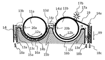
- FIG. 3 shows an example of a magnetic separation portion of a cohesive magnetic device using the two magnetic drums of the present invention.
- the magnetic drum 21b in which the magnetic drum 21a rotating in the rotation direction 22a in the direction opposite to the flow including the flocs rotates in the same direction 22b, is arranged in the front-rear direction.
- a fluid containing flocs from the agglomerates flows toward the magnetic drum 21a in a direction 28a opposite to the direction of gravity 99. Since the center of the flow path is the fastest, as in the velocity distribution 23a in the fluid, the flocs 24 gather in the center.
- the floc 24a heads toward the magnetic drum 21a on the flow toward the magnetic drum 21a, and is further attracted by the magnetic force of the magnet on the surface of the magnetic drum 21a. Is adsorbed on.
- the flocs 24b attracted by magnetic force to the surface of the magnetic drum 21a adhere to the magnetic drum 21a rotating in the rotation direction 22a and are separated from the magnetic drum 21a by the scraper 29a and the brush 27a pressed against the magnetic drum 21a.
- the flock 24c is collected by the flock collection unit 30 by being moved on the scraper 29a.
- the rotation speed of the magnetic drum 21a needs to be low so that the vortex does not destroy the flocs, which is controlled by observing the aggregated state of the flocs.
- the flow direction of the fluid can be greatly changed by the protrusion 25b, and as a result.
- the flock advances toward the magnetic drum 21b, and the flock 24d adheres to the magnetic drum 21b by magnetic force.
- the flow directions of the fluid and the magnetic drum 21b are the same, no force such as shearing is applied from the fluid, so that the flocs 24d on the surface of the magnetic drum 21b are not peeled off by the fluid.
- the magnetic drum 21b rotates in the rotation direction 22b, and the flock 24d on the magnetic drum 21b is written down by the scraper 29b and the brush 27b that are in pressure contact with each other, and is collected by the flock collection unit 30 as shown in the flock 24c.
- the flock collection unit 30 can be integrated into one, so that the cost can be reduced.
- filter separation as shown in FIG. 8 may be used. The same effect can be achieved by reducing the mesh of the filter to 47 microns or less to meet the removal criteria of the ballast water purifier.
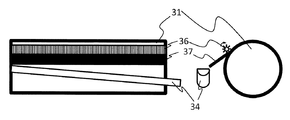
- FIG. 4 shows an example of a flock recovery unit of the cohesive magnetic separation device of the present invention.
- the magnetic drum 31, the scraper 37 that has been pressure-welded, and the brush roller 36 for peeling off the flocs attracted by magnetic force on the surface of the magnetic drum 31 are mainly composed of the collecting unit 34.
- the flock moved from the magnetic drum 31 onto the scraper 37 by the brush roller 36 is further moved by gravity and collected by the flock recovery unit 34. Since the flock recovery section 34 is arranged obliquely, the flock moves by gravity and is discharged from the end portion of the flock recovery section 34.
- the flock recovery unit 34 has a semi-cylindrical shape in order to recover the flock, but may have a concave shape or an inverted triangular cross section.
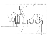
- FIG. 5 shows an example of a block diagram of the cohesive magnetic separation device of the present invention.
- the fluid 59 flows into the coagulation magnetic separation device 55, an appropriate amount of coagulant is charged from the coagulant storage tank 40, and an appropriate amount of magnetite is charged from the magnetite solution storage tank 41, and the fluid 59 is stirred by the stirring unit 43 in the rapid stirring device 42.
- Make microflock The order of adding the inorganic flocculant and magnetite is arbitrary, and they may be added at the same time.
- an organic flocculant 46 such as a polymer is added and stirred by the stirring unit 45 in the slow speed stirring device 44 to form a floc having a size of several hundred microns to several millimeters.
- the flocs enter the separation section, and the fluid containing the flocs accelerated by the rotational force of the non-magnetic rotating drum 49 goes toward the magnetic drum 50.
- the scraper 52 that is in pressure contact with the surface of the magnetic drum 50 and the flocs that are attached by the brush roller 51 are written off from the surface. Plankton and microflocs in the fluid 59 are aggregated into flocs, which are removed from the fluid by the magnetic drum 50.
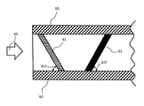
- FIG. 6 shows an example of the slit mechanism for breaking the plastic floating in the sea of the present invention.
- the seawater 63 is sucked into the take-in pipe 60 by the ballast pump, although not shown.
- the slit portion 61 is installed at an arbitrary angle 611 with respect to the fluid to be sucked.
- a slit 62 is provided in the subsequent stage at an arbitrary angle 622 different from the angle 611 with respect to the fluid to be sucked.
- the angle 611 and the angle 622 have an acute angle and an obtuse angle in order to prevent the drifting plastic from being clogged between the slit 61 and the slit 62, and the inflow so that a shearing force acts. It is arranged at an arbitrary angle in the direction.
- the angle 611 and the angle 622 may be right angles. Further, the number of slit portions may be singular.
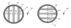
- FIG. 7 shows an embodiment of the slit portion of the slit mechanism for breaking the plastic floating in the sea of the present invention.
- the slit 61 portion shown in FIG. 6 is composed of slit plates 61a, 61b and 61c.
- the slit portion 62 shown in FIG. 6 is composed of slit plates 62a, 62b, and 62c.
- the cross sections of the slit plates 61a, 61b, 61c, 62a, 62b, 62c have acute angles 61x, 65x in the inflow direction. It is sharpened to break the inflowing plastic.
- intervals 65a, 65b, 65c, 65d of the slits 61a, 61b, 61c, 62a, 62b, 62c are evenly spaced. However, considering that the central flow is the maximum flow, the intervals 65a and 65d may be wider than the intervals 65b and 65c. This has the effect of reducing the probability that the plastic waste will be clogged with the slits.
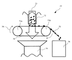
- FIG. 8 shows an embodiment of the broken plastic recovery mechanism of the present invention.
- a fluid 73 such as seawater containing the plastic 77 broken by the slit mechanism described above flows in from the pipe 72.
- the endless belt filter 70 made of an arbitrary mesh size filter continuously rotates between the rollers 71a and 71b, and the fluid 73 containing the broken plastic passes between the rollers 71a and 71b.
- the endless belt filter 70 holds and moves the broken plastic 77, is separated by the scraper 75 that is in pressure contact with the endless belt filter 70, and is placed in the flock recovery tank 76. Further, the fluid 73 from which the broken plastic 77 has been removed flows into the pipe 74.
- the fluid 73 contains fine suspended matter such as microplastic or plankton, and the fluid 73 is sent to the above-mentioned cohesive magnetic separation device 55 and is coagulated magnetically separated as the fluid 59.
- the recovery mechanism is installed after the magnetic separation mechanism, and an object that cannot be magnetically separated is removed by a filter.
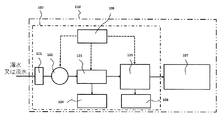
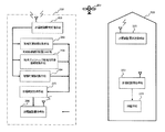
- FIG. 9 shows an example of the marine plastic, microplastic and ballast water purification system of the present invention.
- the marine plastic, microplastic and ballast water purification system 100 is mounted on a ship and has a slit mechanism 101 for breaking the plastic, a pump 102 for supplying and draining seawater or fresh water, and a number of broken plastics and the like.
- a recovery mechanism 103 that collects large suspended matter of 10 mm or more, a recovery tank 104 that temporarily stores the collected suspended matter, and a small suspended matter of less than several tens of mm such as microplastic and plankton.
- the cohesive magnetic separation device 105 may have a mechanism that combines a filter such as a ceramic filter with ozone or ultraviolet rays.
- the treated water is temporarily loaded in the ballast tank 107.
- FIG. 10 shows an example of an operation method of the marine plastic, microplastic and ballast water purification system of the present invention.
- the planned route information center 210 from the sea area traffic information acquisition means 202, the marine plastic information collection means 203, the geographical information collection means 204, the planned route generation means 295, the planned route request receiving means 201, and the planned route provision 206. It is made up.
- the sea area traffic information acquisition means 202 collects information such as an automatic identification system for ships collected from a base station.
- the marine plastic information collecting means 203 collects information on the pollution status of marine plastic in the sea area collected by the satellite 200.
- the geographical information acquisition means 202 acquires the geographical information of the position of the own ship, the destination port, and the sea area between them included in the planned route request signal.
- the planned route generation means 205 generates a planned route based on the information collected by the above-mentioned regional traffic information acquisition means 202, the marine pollution information collecting means 203 such as marine plastic, and the geographical information collecting means 204.
- the ship 220 has a planned route request transmitting means 221 and a planned route receiving means 222, and has a steering means 223 that reflects the result.
- Marine pollution removal work for marine plastics, etc. The results of marine pollution removal work (removed sea area, amount of removed marine pollutants, etc.) are transmitted to the Planned Route Information Center 210.
- the Planned Route Information Center transmits this information to public organizations such as the International Maritime Organization (IMO) and environmental protection groups.
- International organizations such as the International Maritime Organization and environmental protection groups will disclose this information and formulate strategies for marine pollution control.
- IMO International Maritime Organization
- the recovered marine pollutants such as marine plastics are purchased as industrial waste by the government and local governments at the port of call, and the vessels equipped with the marine plastics, microplastics and ballast water purification system are valuable resources such as oil.
- the vessels equipped with the marine plastics, microplastics and ballast water purification system are valuable resources such as oil.
- he is in charge of marine cleaning work.
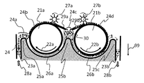
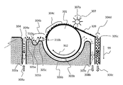
- FIG. 11 shows an example of a magnetic separation unit of the cohesive magnetic separation device of the present invention.
- a magnetic drum 301 in which a magnet is arranged near the surface and a floc 304 containing a magnetic substance such as magnetite are attached to the magnetic drum 301 along a flow 308a from an agglomerate portion (not shown). It flows in the direction opposite to the direction of gravity 99.
- the flow velocity distribution 303a in the flow 308a has the highest flow velocity in the center and the slowest flow velocity on the wall surface. Therefore, according to Bernoulli's equation, the flocs are gathered in the central flow with a high flow velocity.
- the direction of the flow is changed by about 180 degrees by the protrusion 305a having an arbitrary curvature, and the arbitrary curvature is changed in the subsequent stage. It flows along the recess 305b.
- the recess 305b has a structure like a protrusion 305c and a waterfall basin, and forms a vortex 310a. Due to the vortex 310a, the floc 304b floats on the water surface due to the fluid resistance generated because it is larger than the fluid molecule. The flock flows toward the magnetic drum 301.
- the rotation direction of the magnetic drum 301 is opposite to that of the fluid flow 303b, a vortex 310b is created, the fluid velocities cancel each other out, and the flow velocity of the floc 4a becomes low.
- the floc 304a having a low flow velocity is attracted by the magnetic force of the magnet of the magnetic drum 1, approaches the magnetic drum 301 by the magnetic force, and is attracted by the magnetic force. Since the resistance acting on the flock 304a is mainly surface tension, the flock 304a is not easily broken.
- the magnetic drum 301 rotates 302 in the direction opposite to the flow 303b, so that the flock 304b on the drum is immediately separated from the water.
- the contact area of the magnetic drum 301 required for the magnetic drum 301 to magnetically separate the flocs 304a may be as small as several mm above and below the water surface. The reason is that when the flock 304 is attached, the magnetic drum 301 rotates and a new surface to which the flock is not attached appears. Therefore, in order to attach the flock by magnetic force, the actual with the flock of the magnetic drum 310 is necessary. The contact area is small.
- the magnetic drum 1 does not have to be broken due to fluid resistance, and it is not necessary to consider the moving time until the flocs adhere to the magnetic drum 1 by magnetic force against the fluid resistance as shown in [Patent Document 1]. Therefore, the magnetic drum 310 can be miniaturized.
- the flock 304c on the magnetic drum 301 is separated from the magnetic drum 301 by the scraper 309 pressed against the magnetic drum 301 and the brush roller 307 rotating in the rotation direction 307b opposite to the rotation direction 302, and the flock 304b is separated from the magnetic drum 301 by the scraper 309. Move up.
- the flock 304b is recovered by free fall due to gravity like the flock 304d.
- the treated water from which the flocs have been removed flows along the magnetic drum 301 as shown in the flow 303b, and the direction of the flow can be changed by about 180 degrees at the protrusion 305c.
- the treated water flows in the flow velocity distribution 303c and is discharged in the flow 8b. Further, the floc 4c is discharged in the flow 308c.
- ballast water and sediments of the ship are used by the International Maritime Organization (IMO).
- IMO International Maritime Organization
- a treaty for regulation and control (hereinafter referred to as the treaty) has been enacted.
- the mainstream ballast water treatment method is a sterilization method using ultraviolet rays, ozone, hypochlorous acid, etc.
- the problem of marine pollution caused by the above plastics and microplastics cannot be solved.
- the present invention provides a method for simultaneously solving the problem of ecosystem destruction caused by ballast water and the problem of marine pollution caused by plastics and microplastics.
Landscapes
- Engineering & Computer Science (AREA)
- Ocean & Marine Engineering (AREA)
- Chemical & Material Sciences (AREA)
- Combustion & Propulsion (AREA)
- Mechanical Engineering (AREA)
- Environmental & Geological Engineering (AREA)
- Health & Medical Sciences (AREA)
- Public Health (AREA)
- Radar, Positioning & Navigation (AREA)
- Remote Sensing (AREA)
- Physics & Mathematics (AREA)
- General Physics & Mathematics (AREA)
- Separation Of Suspended Particles By Flocculating Agents (AREA)
- Traffic Control Systems (AREA)
Priority Applications (1)
| Application Number | Priority Date | Filing Date | Title |
|---|---|---|---|
| US17/595,216 US11857980B2 (en) | 2019-11-14 | 2020-09-23 | Flocculation and magnetic separation device; system for purifying marine plastic, microplastic, and ballast water having the flocculation and magnetic separation device; ship equipped with the system; and operation method of the ship |
Applications Claiming Priority (2)
| Application Number | Priority Date | Filing Date | Title |
|---|---|---|---|
| JP2019217469A JP7065530B2 (ja) | 2019-11-14 | 2019-11-14 | 凝集磁気分離装置、その凝集磁気分離装置を備えた海洋プラスチック・マイクロプラスチック及びバラスト水浄化システム、およびそれを搭載した船舶、並びにその船舶の運航方法 |
| JP2019-217469 | 2019-11-14 |
Publications (1)
| Publication Number | Publication Date |
|---|---|
| WO2021095383A1 true WO2021095383A1 (ja) | 2021-05-20 |
Family
ID=75912223
Family Applications (1)
| Application Number | Title | Priority Date | Filing Date |
|---|---|---|---|
| PCT/JP2020/037045 Ceased WO2021095383A1 (ja) | 2019-11-14 | 2020-09-23 | 凝集磁気分離装置および搭載船舶とその運航方法 |
Country Status (3)
| Country | Link |
|---|---|
| US (1) | US11857980B2 (https=) |
| JP (1) | JP7065530B2 (https=) |
| WO (1) | WO2021095383A1 (https=) |
Cited By (4)
| Publication number | Priority date | Publication date | Assignee | Title |
|---|---|---|---|---|
| CN114430942A (zh) * | 2022-01-19 | 2022-05-06 | 杨梨 | 一种改善水环境的生态修复装置 |
| CN114920415A (zh) * | 2022-05-13 | 2022-08-19 | 中国科学院生态环境研究中心 | 水环境中纳塑料的分离富集方法以及测定方法 |
| DE102022001154A1 (de) | 2022-04-01 | 2023-10-05 | Mitra Nikpay | Verfahren und Vorrichtung zur Abtrennung von Kunststoffpartikeln mit Magnetfilter |
| CN118206198A (zh) * | 2024-05-20 | 2024-06-18 | 江苏江洲环保科技有限公司 | 一种电镀污水处理设备及处理方法 |
Families Citing this family (7)
| Publication number | Priority date | Publication date | Assignee | Title |
|---|---|---|---|---|
| JP6948742B1 (ja) | 2021-05-13 | 2021-10-13 | 株式会社Ambitious Technologies | 凝集サイクロン装置、それを用いた海洋プラスチック除去システム及びそのシステムを搭載した船舶並びにその船舶の運航方法 |
| CN114917671A (zh) * | 2022-05-13 | 2022-08-19 | 中国水产科学研究院渔业机械仪器研究所 | 一种池塘污物收集去除设备 |
| CN116142374B (zh) * | 2022-12-13 | 2026-02-10 | 中国船舶重工集团公司第七一九研究所 | 格栅、自流循环系统及船舶系统 |
| KR102899228B1 (ko) * | 2022-12-28 | 2025-12-12 | (주)코아이 | 싱글 친수 래쳇 드럼 유회수기 |
| KR102899225B1 (ko) * | 2022-12-28 | 2025-12-11 | (주)코아이 | 듀얼 친수 래쳇 드럼 유회수기 |
| WO2024143902A1 (ko) * | 2022-12-28 | 2024-07-04 | (주)코아이 | 친수 래쳇 드럼 유회수기 |
| CN119080185B (zh) * | 2024-11-04 | 2025-01-03 | 山东省水利科学研究院 | 一种机械制砂用高效废水处理装置 |
Citations (6)
| Publication number | Priority date | Publication date | Assignee | Title |
|---|---|---|---|---|
| JP2008513779A (ja) * | 2004-09-22 | 2008-05-01 | ケネス リトヴァック, | 航行支援方法およびシステム |
| JP2009101341A (ja) * | 2007-10-01 | 2009-05-14 | Hitachi Plant Technologies Ltd | 磁気ディスク及びその製作方法並びに磁気分離装置 |
| JP2011143330A (ja) * | 2010-01-12 | 2011-07-28 | Hitachi Plant Technologies Ltd | 廃水処理方法及び廃水処理装置 |
| JP2011183271A (ja) * | 2010-03-05 | 2011-09-22 | Hitachi Plant Technologies Ltd | 磁気分離装置及び廃水処理装置 |
| JP2013166544A (ja) * | 2013-02-25 | 2013-08-29 | Mitsubishi Heavy Ind Ltd | バラスト水処理システム |
| CN209619975U (zh) * | 2018-12-11 | 2019-11-12 | 杨睿瑄 | 海洋塑料垃圾收集栏板 |
Family Cites Families (9)
| Publication number | Priority date | Publication date | Assignee | Title |
|---|---|---|---|---|
| JP4413027B2 (ja) * | 2004-02-03 | 2010-02-10 | 株式会社日立製作所 | 船舶搭載型汚濁水浄化装置 |
| JP4798691B2 (ja) * | 2005-02-01 | 2011-10-19 | 三井造船株式会社 | バラスト水の処理装置 |
| JP4272669B2 (ja) | 2006-09-29 | 2009-06-03 | 社団法人日本海難防止協会 | 船舶バラスト水の処理装置 |
| CA2805925A1 (en) * | 2013-02-06 | 2014-08-06 | Jonathan K. Biley | Method and apparatus for removing seaweed from the ocean and beach |
| JP5945309B2 (ja) | 2014-10-09 | 2016-07-05 | 三菱重工業株式会社 | バラスト水処理システム |
| JP2016101539A (ja) | 2014-11-27 | 2016-06-02 | 株式会社日立製作所 | 磁気分離装置、及び原水処理装置 |
| JP7042469B2 (ja) | 2016-10-28 | 2022-03-28 | 国立研究開発法人 海上・港湾・航空技術研究所 | 船舶の衝突リスク低減方法、船舶の衝突リスク低減システム、及び計画航路情報提供センター |
| JP2018089561A (ja) * | 2016-12-01 | 2018-06-14 | 住友重機械ファインテック株式会社 | マグネットセパレータ |
| US11273580B2 (en) * | 2018-05-30 | 2022-03-15 | Philip John Milanovich | Waste management system |
-
2019
- 2019-11-14 JP JP2019217469A patent/JP7065530B2/ja active Active
-
2020
- 2020-09-23 WO PCT/JP2020/037045 patent/WO2021095383A1/ja not_active Ceased
- 2020-09-23 US US17/595,216 patent/US11857980B2/en active Active
Patent Citations (6)
| Publication number | Priority date | Publication date | Assignee | Title |
|---|---|---|---|---|
| JP2008513779A (ja) * | 2004-09-22 | 2008-05-01 | ケネス リトヴァック, | 航行支援方法およびシステム |
| JP2009101341A (ja) * | 2007-10-01 | 2009-05-14 | Hitachi Plant Technologies Ltd | 磁気ディスク及びその製作方法並びに磁気分離装置 |
| JP2011143330A (ja) * | 2010-01-12 | 2011-07-28 | Hitachi Plant Technologies Ltd | 廃水処理方法及び廃水処理装置 |
| JP2011183271A (ja) * | 2010-03-05 | 2011-09-22 | Hitachi Plant Technologies Ltd | 磁気分離装置及び廃水処理装置 |
| JP2013166544A (ja) * | 2013-02-25 | 2013-08-29 | Mitsubishi Heavy Ind Ltd | バラスト水処理システム |
| CN209619975U (zh) * | 2018-12-11 | 2019-11-12 | 杨睿瑄 | 海洋塑料垃圾收集栏板 |
Non-Patent Citations (1)
| Title |
|---|
| KANEDA, TAKESHI: "Current State and Challenges of Marine Plastic Waste Problem", JMC JOURNAL, vol. 67, no. 5, pages 1 - 16 * |
Cited By (6)
| Publication number | Priority date | Publication date | Assignee | Title |
|---|---|---|---|---|
| CN114430942A (zh) * | 2022-01-19 | 2022-05-06 | 杨梨 | 一种改善水环境的生态修复装置 |
| CN114430942B (zh) * | 2022-01-19 | 2024-03-26 | 安能重庆建设发展有限公司 | 一种改善水环境的生态修复装置 |
| DE102022001154A1 (de) | 2022-04-01 | 2023-10-05 | Mitra Nikpay | Verfahren und Vorrichtung zur Abtrennung von Kunststoffpartikeln mit Magnetfilter |
| CN114920415A (zh) * | 2022-05-13 | 2022-08-19 | 中国科学院生态环境研究中心 | 水环境中纳塑料的分离富集方法以及测定方法 |
| CN114920415B (zh) * | 2022-05-13 | 2024-02-02 | 中国科学院生态环境研究中心 | 水环境中纳塑料的分离富集方法以及测定方法 |
| CN118206198A (zh) * | 2024-05-20 | 2024-06-18 | 江苏江洲环保科技有限公司 | 一种电镀污水处理设备及处理方法 |
Also Published As
| Publication number | Publication date |
|---|---|
| US20220219176A1 (en) | 2022-07-14 |
| JP2021079930A (ja) | 2021-05-27 |
| US11857980B2 (en) | 2024-01-02 |
| JP7065530B2 (ja) | 2022-05-12 |
Similar Documents
| Publication | Publication Date | Title |
|---|---|---|
| JP7065530B2 (ja) | 凝集磁気分離装置、その凝集磁気分離装置を備えた海洋プラスチック・マイクロプラスチック及びバラスト水浄化システム、およびそれを搭載した船舶、並びにその船舶の運航方法 | |
| JP2021079930A5 (https=) | ||
| Devi et al. | Removal of nanoplastics in water treatment processes: A review | |
| Pramanik et al. | Understanding the fragmentation of microplastics into nano-plastics and removal of nano/microplastics from wastewater using membrane, air flotation and nano-ferrofluid processes | |
| JP4186523B2 (ja) | 排水浄化装置および排水浄化システム | |
| JP6948742B1 (ja) | 凝集サイクロン装置、それを用いた海洋プラスチック除去システム及びそのシステムを搭載した船舶並びにその船舶の運航方法 | |
| US20080073279A1 (en) | High Rate Clarification of Cooling Water Using Magnetite Seeding and Separation | |
| EP1676818A1 (en) | Filtering and purifying system | |
| Ning et al. | Tandom reverse osmosis process for zero-liquid discharge | |
| KR101020238B1 (ko) | 나노 입자 공기 부상을 이용한 하ㆍ폐수 처리 장치 및 방법 | |
| JP2005111424A (ja) | 流体内からの被除去物除去処理方法及び装置と汚泥分離回収装置 | |
| CN209428272U (zh) | 一种钢铁工业浓盐水处理装置 | |
| AU2020378058B2 (en) | Accelerated settlement of flocs after electrocoagulation/electrochemical process using ballasted flocculation | |
| JP2012152708A (ja) | 凝集磁気分離装置 | |
| Rao et al. | Review on an integrated pre-treatment system to reduce membrane accelerated biofouling during red tide occurrences in Oman | |
| Colic et al. | Case study: fish processing plant wastewater treatment | |
| JP2003334562A (ja) | 浄水処理方法及びその装置 | |
| US20210086193A1 (en) | Process and apparatus for cleaning and discharging waste solids from contaminated fluids | |
| JPS5966393A (ja) | 廃水処理における懸濁物の分離装置 | |
| JP4381154B2 (ja) | 水中の凝集物の回収方法とこれに用いる水中の凝集物の回収具 | |
| CN204625429U (zh) | 污水处理成套设备 | |
| Kaur et al. | Enhanced removal of microplastics using microflotation | |
| JP4655466B2 (ja) | 濾過浄化装置 | |
| JP4142504B2 (ja) | 高速浮上分離方法及び装置 | |
| US20150376044A1 (en) | Water purification process with water pretratment |
Legal Events
| Date | Code | Title | Description |
|---|---|---|---|
| 121 | Ep: the epo has been informed by wipo that ep was designated in this application |
Ref document number: 20888470 Country of ref document: EP Kind code of ref document: A1 |
|
| NENP | Non-entry into the national phase |
Ref country code: DE |
|
| 122 | Ep: pct application non-entry in european phase |
Ref document number: 20888470 Country of ref document: EP Kind code of ref document: A1 |