WO2021090913A1 - 光ファイバ - Google Patents
光ファイバ Download PDFInfo
- Publication number
- WO2021090913A1 WO2021090913A1 PCT/JP2020/041539 JP2020041539W WO2021090913A1 WO 2021090913 A1 WO2021090913 A1 WO 2021090913A1 JP 2020041539 W JP2020041539 W JP 2020041539W WO 2021090913 A1 WO2021090913 A1 WO 2021090913A1
- Authority
- WO
- WIPO (PCT)
- Prior art keywords
- optical fiber
- less
- coating layer
- glass portion
- outer diameter
- Prior art date
- Legal status (The legal status is an assumption and is not a legal conclusion. Google has not performed a legal analysis and makes no representation as to the accuracy of the status listed.)
- Ceased
Links
Images


Classifications
-
- G—PHYSICS
- G02—OPTICS
- G02B—OPTICAL ELEMENTS, SYSTEMS OR APPARATUS
- G02B6/00—Light guides; Structural details of arrangements comprising light guides and other optical elements, e.g. couplings
- G02B6/02—Optical fibres with cladding with or without a coating
- G02B6/02395—Glass optical fibre with a protective coating, e.g. two layer polymer coating deposited directly on a silica cladding surface during fibre manufacture
-
- C—CHEMISTRY; METALLURGY
- C03—GLASS; MINERAL OR SLAG WOOL
- C03C—CHEMICAL COMPOSITION OF GLASSES, GLAZES OR VITREOUS ENAMELS; SURFACE TREATMENT OF GLASS; SURFACE TREATMENT OF FIBRES OR FILAMENTS MADE FROM GLASS, MINERALS OR SLAGS; JOINING GLASS TO GLASS OR OTHER MATERIALS
- C03C25/00—Surface treatment of fibres or filaments made from glass, minerals or slags
- C03C25/10—Coating
- C03C25/104—Coating to obtain optical fibres
- C03C25/106—Single coatings
-
- G—PHYSICS
- G02—OPTICS
- G02B—OPTICAL ELEMENTS, SYSTEMS OR APPARATUS
- G02B6/00—Light guides; Structural details of arrangements comprising light guides and other optical elements, e.g. couplings
- G02B6/44—Mechanical structures for providing tensile strength and external protection for fibres, e.g. optical transmission cables
- G02B6/4401—Optical cables
- G02B6/4407—Optical cables with internal fluted support member
- G02B6/4409—Optical cables with internal fluted support member for ribbons
-
- G—PHYSICS
- G02—OPTICS
- G02B—OPTICAL ELEMENTS, SYSTEMS OR APPARATUS
- G02B6/00—Light guides; Structural details of arrangements comprising light guides and other optical elements, e.g. couplings
- G02B6/44—Mechanical structures for providing tensile strength and external protection for fibres, e.g. optical transmission cables
- G02B6/4401—Optical cables
- G02B6/4429—Means specially adapted for strengthening or protecting the cables
- G02B6/443—Protective covering
- G02B6/4432—Protective covering with fibre reinforcements
- G02B6/4433—Double reinforcement laying in straight line with optical transmission element
Definitions
- the present invention relates to an optical fiber, specifically, an optical fiber that can be used for an optical fiber cable.
- the optical fiber As a means of increasing the number of mounting cores and mounting density of the optical fiber, it is conceivable to reduce the diameter of the optical fiber.
- the optical fiber is easily affected by the lateral pressure, and the microbend loss, which is the optical loss caused by the so-called minute bending in which the axis of the optical fiber is slightly bent, can be increased.
- the elastic modulus of the optical fiber coating and the glass transition point are adjusted to reduce the coating thickness of the optical fiber, whereby microbend loss is suppressed even when the diameter of the optical fiber is reduced. It is stated that it can be done.
- the microbend loss propagates the optical fiber with parameters related to the optical fiber geometry such as the coating thickness of the optical fiber, the outer diameter of the glass forming the core and the clad, the Young ratio of the glass, and the Young ratio of the coating. It tends to be affected by parameters related to the optical characteristics of the optical fiber, such as the propagation constant of the light.
- the coating thickness is taken into consideration as the above parameter in terms of suppressing microbend loss, but parameters other than the coating thickness are not taken into consideration. Therefore, there is a demand for an optical fiber capable of suppressing microbend loss in consideration of various parameters that affect microbend loss.
- an object of the present invention is to provide an optical fiber capable of suppressing microbend loss.
- the present invention is an optical fiber including a core and a glass portion including a clad surrounding the core, a primary coating layer covering the clad, and a secondary coating layer covering the primary coating layer.
- the spring coefficient of the primary coating layer is ⁇ s (MPa)
- the bending rigidity of the glass portion is H f (MPa ⁇ ⁇ m 4 )
- the deformation resistance of the secondary coating layer is D 0 (MPa)
- the bending rigidity of the secondary coating layer is ⁇ s (MPa)
- the outer diameter of the glass portion is d f ( ⁇ m), the radius of the outer peripheral surface of the primary coating layer is R p ( ⁇ m), the radius of the outer peripheral surface of the secondary coating layer is R s ( ⁇ m), and the primary coating layer is When the thickness of the secondary coating layer is t p ( ⁇ m) and the thickness of the secondary coating layer is t s ( ⁇ m), Propagation constant in the represented geometry microbend loss characteristics F MyuBL_G of the optical fiber (GPa -1 ⁇ ⁇ m -10.5 ⁇ 10 -27), the propagation constant and the radiation mode in the waveguide mode propagating through the optical fiber When the difference from is the propagation constant difference ⁇ (rad / m), Optical microbend loss characteristic F ⁇ BL_ ⁇ (1 / (rad / ⁇ m) 8 ) of the optical fiber represented by Using, The value of the microbend loss characteristic factor F ⁇ BL_G ⁇ ([GPa -1 ⁇ ⁇ m -2.5 / rad 8 ] ⁇
- Non-Patent Document 1 J. Baldauf, et al., “Relationship of Mechanical Characteristics of Dual Coated Single Mode Optical Fibers and Microbending Loss,” IEICE Trans. Communi., Vol. E76-B, vol. No. 4, 1993.
- Non-Patent Document 2 K. Petermann, et al., “Upper and Lower Limits for the Microbending Loss in Arbitrary Single-Mode Fibers,” J. Lightwave technology, vol. LT-4, no .1, pp.
- Non-Patent Document 3 Ogoshi et al., “Optical Fiber,” Ohm, pp.235-239, 1989.
- Non-Patent Document 4 P. Sillard, et. Effects of both optical fiber geometry and optical properties, as described in al., “Micro-Bend Losses of Trench-Assisted Single-Mode Fibers,” ECOC2010, We.8.F.3, 2010.) Tend to receive.
- the geometry of the optical fiber is a parameter related to the structure of the optical fiber, and in the present invention, the spring coefficient ⁇ s of the primary coating layer in the optical fiber, the flexural rigidity H f of the glass portion, and the deformation resistance D of the secondary coating layer D.
- microbend loss is a phenomenon caused by mode coupling in which the waveguide mode propagating in the optical fiber is coupled with the radiation mode.
- mode coupling is considered to occur due to the above-mentioned minute bending, and is a propagation constant difference which is a difference between the propagation constant of the light propagating in the optical fiber in the waveguide mode and the propagation constant in the radiation mode. It is said to be determined by ( ⁇ ).
- the above-mentioned optical characteristics of the optical fiber are parameters related to the characteristics of light propagating in the optical fiber, and in the present invention, the above-mentioned propagation constant difference ⁇ (rad / m) is meant.
- the microbend loss of such an optical fiber is a transmission loss measured in a state where the optical fiber is wound in one layer with a predetermined tension on a roughened bobbin body portion, and the optical fiber is unwound from the bobbin. It may be represented by the value of sandpaper tension winding loss increase, which is the difference from the transmission loss measured with almost no tension applied. The smaller the value of such sandpaper tension winding loss increase, the smaller the microbend loss of the optical fiber.
- a so-called tape slot type cable configured by accommodating a plurality of tape core wires in each of a plurality of slots formed in a holder for holding the tape core wire.
- Ribbon Slotted Core Cable and a small-diameter high-density cable (UHDC: Ultra-High Density Cable) configured by densely arranging tape core wires inside the cable without using the above holder are known.
- UHDC Ultra-High Density Cable
- the present inventor has diligently studied the relationship between the increase in sandpaper tension winding loss and the above-mentioned various parameters in the optical fiber used for the optical fiber cable. As a result, it was found that the value of the microbend loss characteristic factor F ⁇ BL_G ⁇ represented by the above formula has a high correlation with the value of the increase in sandpaper tension winding loss. That is, the present inventor has found that the value of the microbend loss characteristic factor has a substantially positive proportional relationship with the value of the increase in sandpaper tension winding loss.
- the present inventor conducted sandpaper when the value of the microbend loss characteristic factor was 6.1 ([GPa -1 ⁇ ⁇ m ⁇ 2.5 / rad 8 ] ⁇ 10-12). It was found that the value of the increase in tension winding loss was slightly smaller than 0.6 dB / km. As described above, the value of the microbend loss characteristic factor and the value of the sandpaper tension winding loss increase are generally in a positive proportional relationship with each other. Therefore, by setting the value of the microbend loss characteristic factor of the optical fiber to 7183 GPa 3 ⁇ nm 2.5 ⁇ rad 8 or less, the microbend loss can be suppressed to the extent that it can be applied to the tape slot type cable.
- microbend loss can be suppressed.
- the value of the microbend loss characteristic factor is 4.1 ([GPa -1 ⁇ ⁇ m ⁇ 2.5 / rad 8 ] ⁇ 10-12) or less.
- the tape core wires are densely arranged as described above in the small diameter high density cable. Therefore, similarly to the tape slot type cable, the optical fiber constituting the tape core wire receives lateral pressure, and microbend loss may occur.
- the small-diameter high-density cable is slotless as described above, and since all the tape core wires are densely arranged inside the cable, the tape core wires are arranged in a plurality of grooves. The optical fiber tends to be subjected to a large lateral pressure. Therefore, it is recommended to use an optical fiber having a smaller microbend loss than the optical fiber used for the tape slot type cable in the small diameter high density cable. From this point of view, it is preferable to use an optical fiber in which the sandpaper tension winding loss increase value is suppressed to 0.34 dB / km or less in the small-diameter high-density cable.
- the value of the microbend loss characteristic factor corresponding to the value of the increase in sandpaper tension winding loss (0.34 dB / km) is 4.1 ([GPa -1 ⁇ ⁇ m -2.5 / km). rad 8 ] ⁇ 10-12 ) was found. Therefore, by setting the value of the microbend loss characteristic factor of the optical fiber to 4.1 ([GPa -1 ⁇ ⁇ m -2.5 / rad 8 ] ⁇ 10-12 ) or less, it can be applied to small-diameter high-density cables. Microbend loss can be suppressed to the extent possible.
- the coating thickness which is the sum of the thickness of the primary coating layer and the thickness of the secondary coating layer, is 42.0 ⁇ m or less.
- the optical fiber used for the optical fiber cable constituting the communication infrastructure generally has a coating thickness of about 60 ⁇ m. Therefore, if the coating thickness is 42.0 ⁇ m or less, it is possible to realize an optical fiber having a smaller diameter than a general optical fiber constituting a communication infrastructure.
- the value of the microbend loss characteristic factor is determined by various parameters as described above, and the parameters include the thickness of the primary coating layer and the thickness of the secondary coating layer.
- the value of the microbend loss characteristic factor can be set to 6.1 ([GPa] by adjusting other parameters. -1 ⁇ ⁇ m -2.5 / rad 8 ] ⁇ 10-12 ) or less, and 4.1 ([GPa -1 ⁇ ⁇ m -2.5 / rad 8 ] ⁇ 10-12 ) or less It can also be. Therefore, even if the coating thickness of the optical fiber of the present invention is 42.0 ⁇ m or less, microbend loss can be suppressed to such an extent that it can be used for a tape slot type cable or a small diameter high density cable.
- the coating thickness is 38.0 ⁇ m or less.
- the coating thickness is 36.5 ⁇ m or less.
- the coating thickness is 34.5 ⁇ m or less.
- the coating thickness is 34.0 ⁇ m or less.
- microbend loss can be suppressed to the extent that it can be used for tape slot type cables and small-diameter high-density cables, and an optical fiber with a smaller diameter can be realized. ..
- the outer diameter of the glass portion may be 65 ⁇ m or more and 100 ⁇ m or less.
- the optical fiber used for the optical fiber cable constituting the communication infrastructure is generally formed so that the outer diameter of the glass portion is 125 ⁇ m. Therefore, if the coating thickness is 42.0 ⁇ m or less and the outer diameter of the glass portion is 100 ⁇ m or less, an optical fiber having a smaller diameter than the general optical fiber constituting the communication infrastructure can be realized. ..
- the value of the microbend loss characteristic factor is determined by various parameters as described above, and the parameters include the coating thickness and the outer diameter of the glass portion.
- the value of the microbend loss characteristic factor is set to 6.1 ([GPa] by adjusting other parameters. -1 ⁇ ⁇ m -2.5 / rad 8 ] ⁇ 10-12 ) or less, and 4.1 ([GPa -1 ⁇ ⁇ m -2.5 / rad 8 ] ⁇ 10-12 ) or less It can also be. Therefore, even if the coating thickness of the optical fiber of the present invention is 42.0 ⁇ m or less and the outer diameter of the glass portion is 100 ⁇ m or less, microbend loss is suppressed to the extent that it can be used for tape slot type cables and small diameter high density cables. Can be done.
- the mechanical bending resistance of the optical fiber can be increased by the amount of the brittle glass being thinned.
- the outer diameter of the glass portion is 90 ⁇ m or less.
- the outer diameter of the glass portion is 80 ⁇ m or less.
- the outer diameter of the glass portion is 75 ⁇ m or less.
- the outer diameter of the glass portion is 70 ⁇ m or less.
- the coating thickness is 42.0 ⁇ m or less
- the mode field diameter at a wavelength of 1310 nm is 7.6 ⁇ m or more and 8.7 ⁇ m or less
- the cable cutoff wavelength is 1260 nm or less
- the zero dispersion wavelength is 1300 nm or more and 1324 nm.
- the zero dispersion slope may be 0.073 ps / km / nm or more and 0.092 ps / km / nm.
- the macrobend loss at a wavelength of 1625 nm when bent at a radius of 10 mm may be 1.5 dB / turn or less.
- the macrobend loss at a wavelength of 1625 nm when bent at a radius of 10 mm may be 0.2 dB / turn or less.
- the macrobend loss at a wavelength of 1625 nm when bent at a radius of 10 mm may be 0.1 dB / turn or less.
- an optical fiber capable of suppressing microbend loss is provided.
- FIG. 3 shows schematic the structure of the cross section perpendicular to the longitudinal direction of the optical fiber cable which concerns on 1st Embodiment of this invention. It is a perspective view which shows typically an example of the optical fiber tape core wire included in the optical fiber cable shown in FIG. It is a figure which shows schematic the structure of the cross section perpendicular to the longitudinal direction of the optical fiber included in the optical fiber tape core wire shown in FIG. It is a figure which shows the structure of the cross section perpendicular to the longitudinal direction of the optical fiber cable which concerns on 2nd Embodiment of this invention. It is a figure which shows the relationship between the value of the microbend loss characteristic factor in the optical fiber shown in FIG. 3 and the increase in sandpaper tension winding loss.
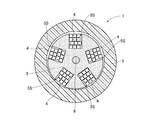
- FIG. 1 is a diagram schematically showing a structure having a cross section perpendicular to the longitudinal direction of the optical fiber cable 1 according to the first embodiment.
- the optical fiber cable 1 is a so-called tape slot type cable (RSCC: Ribbon Slotted Core Cable).
- the optical fiber cable 1 mainly includes a sheath 3, a plurality of tape core wires 4, a holding body 5, and a tensile strength body 6.
- the sheath 3 is a tubular member and may be formed of a thermoplastic resin such as polyethylene.
- the holding body 5 is housed in the internal space of the sheath 3. In this way, the sheath 3 houses the holding body 5 inside and protects the holding body 5.
- the holding body 5 is a member that holds a plurality of tape core wires 4.
- a plurality of slots 5S are formed in the holding body 5, and a plurality of tape core wires 4 are accommodated in each of the slots 5S.
- the tensile strength body 6 is embedded in the substantially center of the holding body 5 in the cross-sectional view of FIG. Such a tensile strength body 6 can prevent the tape core wire 4 from being stretched more than necessary when tension is applied in the longitudinal direction of the tape core wire 4.
- FIG. 2 is a perspective view schematically showing an example of the tape core wire 4.
- the tape core wire 4 of the present embodiment is a so-called intermittent adhesive type tape core wire.
- the tape core wire 4 has a configuration in which a plurality of optical fibers 10 are arranged along a direction perpendicular to the longitudinal direction, and the arranged optical fibers 10 are bonded to each other.
- the tape core wire 4 includes an adhesive portion 4A and a single core portion 4B.
- the adhesive portion 4A is a portion where adjacent optical fibers 10 are adhered to each other, and is provided intermittently at a constant pitch along the longitudinal direction.
- the single core portion 4B is a portion located between the adhesive portions 4A, and is a portion where the optical fibers 10 are not adhered to each other.
- FIG. 1 schematically shows a state in which each tape core wire 4 is bundled in a substantially cylindrical shape.
- FIG. 2 shows an example in which the tape core wire 4 is composed of four optical fibers 10, but this is an example. That is, the number of optical fibers 10 constituting the tape core wire 4 is not particularly limited, and may be less than 4 or more than 4.
- the tape core wire 4 may be composed of a 12-core optical fiber 10. Further, the tape core wire 4 is not limited to the intermittent adhesive type.
- FIG. 3 is a diagram showing a structure of a cross section perpendicular to the longitudinal direction of the optical fiber 10 constituting the tape core wire 4.
- the optical fiber 10 of this embodiment is a single mode optical fiber.
- the optical fiber 10 includes a core 11, a clad 12 that surrounds the core 11 without gaps, a primary coating layer 14 that covers the clad 12, and a secondary coating layer 15 that covers the primary coating layer 14. Is provided as the main configuration.
- the clad 12 has a lower refractive index than the core 11.
- the core 11 may be formed from pure quartz to which no dopant is added, or may be formed from quartz to which germanium (Ge) or the like that increases the refractive index is added as a dopant.
- the clad 12 has a lower refractive index than the core 11.
- the clad 12 may be formed of quartz to which fluorine (F), boron (B), or the like that lowers the refractive index is added as a dopant.
- fluorine (F) fluorine
- B boron
- the clad 12 may be formed of quartz to which chlorine (Cl2) has been added.
- the clad 12 may be a single layer, may be composed of a plurality of layers having different refractive indexes, or may be a pore-assisted type.
- both the core 11 and the clad 12 are formed of quartz (glass). Therefore, the core 11 and the clad 12 are collectively referred to as the glass portion 13. That is, the glass portion 13 includes the core 11 and the clad 12, and the glass portion 13 is covered with the primary coating layer 14.
- the glass portion 13 may also be referred to as an optical fiber bare wire portion.
- the outer diameter (diameter) d f of such a glass portion 13 is generally 125 ⁇ m. However, in the present embodiment, the outer diameter d f of the glass portion 13 can be made smaller than this.
- it can be 65 ⁇ m or more and 100 ⁇ m or less, 65 ⁇ m or more and 90 ⁇ m or less, 65 ⁇ m or more and 80 ⁇ m or less, 65 ⁇ m or more and 75 ⁇ m or less, or 65 ⁇ m or more and 70 ⁇ m or less.
- the reason why the outer diameter d f of the glass portion 13 can be reduced in this way will be described later.
- Primary coating layer 14 is formed, for example, an ultraviolet curable resin or a thermosetting resin, is formed to a thickness on the outside of the glass portion 13 of t p ( ⁇ m).
- the Young's modulus E g of the primary coating layer 14 is lower than the Young's modulus E s of the secondary coating layer 15.
- the radius of the outer peripheral surface of the primary coating layer 14 is R p ( ⁇ m)
- the outer diameter of the primary coating layer 14 is represented by 2 R p
- the radius of the glass portion (d f ⁇ 1/2) is R.
- the secondary coating layer 15 is a layer forming the outermost layer of the optical fiber 10, and is formed of, for example, an ultraviolet curable resin or a thermosetting resin different from the resin forming the primary coating layer 14, and is primary. It is formed on the outside of the coating layer 14 with a thickness of t s ( ⁇ m).
- the secondary coating layer 15 may be formed of an ultraviolet curable resin different from the ultraviolet curable resin forming the primary coating layer 14, and the primary coating layer 14 may be formed of an ultraviolet curable resin. Is formed from a thermosetting resin, it may be formed from a thermosetting resin different from the primary coating layer 14.
- the Young's modulus E s of the secondary coating layer 15 is higher than the Young's modulus E g of the primary coating layer 14.
- the secondary coating layer 15 forming the outermost layer of the optical fiber 10 has a high Young's modulus, so that the glass portion 13 can be appropriately protected from an external force.
- the radius of the outer peripheral surface of the secondary coating layer 15 is R s
- the outer diameter of the secondary coating layer 15, that is, the outer diameter of the optical fiber 10 is represented by 2 R s
- the thickness of the secondary coating layer 15 is described above.
- the outer diameter of the optical fiber used for the optical fiber cable is generally about 240 ⁇ m to 250 ⁇ m. Therefore, the outer diameter of the secondary coating layer 15 may be approximately 240 ⁇ m. However, in the present embodiment, the outer diameter of the secondary coating layer 15 can be made smaller than 240 ⁇ m. For example, it can be about 190 ⁇ m, about 150 ⁇ m to about 160 ⁇ m, or about 125 ⁇ m. The reason why the outer diameter of the secondary coating layer 15, that is, the outer diameter of the optical fiber 10 can be reduced in this way will be described later.
- the coating thickness of the optical fiber used for the optical fiber cable is generally 60 ⁇ m. Degree. Therefore, the coating thickness t of the optical fiber 10 may be about 60 ⁇ m. However, in the present embodiment, the coating thickness t of the optical fiber 10 can be made smaller than 60 ⁇ m. For example, it can be 42.5 ⁇ m or less, 38.0 ⁇ m or less, 36.5 ⁇ m or less, 34.5 ⁇ m or less, or 34.0 ⁇ m or less. be able to. The reason why the coating thickness of the optical fiber 10 can be reduced in this way will be described later.
- the tape core wire 4 including a plurality of such optical fibers 10 is densely housed in the slot 5S of the holder 5.
- the optical fiber cable 1 can accommodate a large number of optical fibers.
- the optical fiber cable 1 accommodates 1000 or more optical fibers.
- the glass portion 13 can be formed to have an outer diameter smaller than that of the glass portion of the general optical fiber, and the coating thickness is the coating of the general optical fiber. It can be formed smaller than the thickness. Therefore, the outer diameter of the optical fiber 10 can be made smaller than the outer diameter of a general optical fiber, and the diameter of the optical fiber 10 can be reduced.
- the size of the tape core wire 4 can be made smaller than the size of a general tape core wire. Therefore, by accommodating the tape core wire 4 having such a small size in the slot 5S, the number of optical fiber cores accommodated in the optical fiber cable 1 can be further increased. Alternatively, the size of the optical fiber cable 1 can be reduced by accommodating the tape core wire 4 having such a small size in the slot 5S.
- the lateral pressure acting on the optical fiber tends to increase.
- the shaft of the optical fiber is slightly bent, and microbend loss may occur.
- the glass portion is susceptible to lateral pressure, and microbend loss may also occur.
- the value of the microbend loss characteristic factor F ⁇ BL_G ⁇ which will be described later, is 6.1 ([GPa -1 ⁇ ⁇ m ⁇ 2.5 / rad 8 ] ⁇ 10-12 ) or less. Is formed in. Therefore, even when the outer diameter and the coating thickness of the glass portion are reduced and the number of cores of the optical fiber 10 accommodated in the slot 5S is increased, the microbend loss can be suppressed. The reason for this will be described in detail below.
- Non-Patent Document 1 J. Baldauf, et al., “Relationship of Mechanical Characteristics of Dual Coated Single Mode Optical Fibers and Microbending Loss,” IEICE Trans. Communi., Vol. E76-B, vol. No. 4, 1993.
- Non-Patent Document 2 K. Petermann, et al., “Upper and Lower Limits for the Microbending Loss in Arbitrary Single-Mode Fibers,” J. Lightwave technology, vol. LT-4, no .1, pp.
- Non-Patent Document 3 Ogoshi et al., “Optical Fiber,” Ohm, pp.235-239, 1989.
- Non-Patent Document 4 P. Sillard, et. Effects of both optical fiber geometry and optical properties, as described in al., “Micro-Bend Losses of Trench-Assisted Single-Mode Fibers,” ECOC2010, We.8.F.3, 2010.) Tend to receive.
- the geometry of the optical fiber is a parameter related to the structure of the optical fiber, and in the present embodiment, the spring coefficient ⁇ s of the primary coating layer in the optical fiber, the flexural rigidity H f of the glass portion, and the deformation resistance of the secondary coating layer.
- D flexural rigidity H 0 of the secondary coating layer, the Young's modulus of the glass portion E g, the Young's modulus E p of the primary coating layer, the Young's modulus E s of the secondary coating layer, the outer diameter d f (glass portion of the glass portion diameter ),
- microbend loss is a phenomenon caused by mode coupling in which the waveguide mode propagating in the optical fiber is coupled with the radiation mode.
- This waveguide mode is, for example, LP01 mode. It is said that such mode coupling is caused by so-called minute bending in which the axis of the optical fiber is slightly bent, and the propagation constant is the difference between the propagation constant in the waveguide mode and the propagation constant in the radiation mode. It is believed to be determined by the difference ( ⁇ ).
- the above-mentioned optical characteristics of the optical fiber are parameters related to the characteristics of light propagating in the optical fiber, and in the present invention, the above-mentioned propagation constant difference ⁇ (rad / m) is meant.
- the microbend loss of such an optical fiber is a transmission loss measured in a state where the optical fiber is wound in one layer with a predetermined tension on a roughened bobbin body portion, and the optical fiber is unwound from the bobbin. It may be represented by the value of sandpaper tension winding loss increase, which is the difference from the transmission loss measured with almost no tension applied. The smaller the value of such sandpaper tension winding loss increase, the smaller the microbend loss of the optical fiber.
- a tape slot type cable such as the optical fiber cable 1 of the present embodiment may cause microbend loss as described above. Therefore, the tape slot type cable has a required characteristic that the value of the increase in sandpaper tension winding loss is 0.6 dB / km or less in consideration of such microbend loss.
- the present inventor has diligently studied the relationship between the increase in sandpaper tension winding loss and the above-mentioned various parameters in the optical fiber used for the optical fiber cable.
- the spring coefficient ⁇ s of the primary coating layer, the bending rigidity H f of the glass portion, the deformation resistance D 0 of the secondary coating layer, the bending rigidity H 0 of the secondary coating layer, and the young ratio E g of the glass portion which are parameters related to the geometry.
- Non-Patent Document 5 K. Kobayashi, et al., “Study of Microbending loss in thin coated fibers and fiber ribbons,” IWCS, pp.386 – 392, 1993.
- the typical value of the constant ⁇ in 1) is “3”. Therefore, the above equation (1) becomes the following equation (4).
- Non-Patent Document 2 and Non-Patent Document 6 CD Hussey, et al., “characterization and design of single-mode optical fiber,” Optical and Quantum Electronics, vol. 14, no. 4, pp. 347 &# According to 8211; 358, 1982.
- the typical value of the constant p in the above equation (2) is "4". Therefore, the above equation (2) becomes the following equation (5).
- the present inventor found that the value of the microbend loss characteristic factor was 6.1 ([GPa -1 ⁇ ⁇ m ⁇ 2.5 / rad 8 ] ⁇ 10-12 ). It was found that the value of the increase in sandpaper tension winding loss was slightly smaller than 0.6 dB / km. As described above, the value of the microbend loss characteristic factor and the value of the sandpaper tension winding loss increase are generally in a positive proportional relationship with each other. Therefore, by setting the value of the microbend loss characteristic factor of the optical fiber to 6.1 ([GPa -1 ⁇ ⁇ m -2.5 / rad 8 ] ⁇ 10-12 ) or less, the required characteristics of the tape slot type cable can be obtained. Microbend loss can be suppressed to the extent that it is satisfied.
- the value of the microbend loss characteristic factor F ⁇ BL_G ⁇ is 6.1 ([GPa -1 ⁇ ⁇ m ⁇ 2.5 / rad 8 ] ⁇ 10-12 ) or less. Is formed as follows. Therefore, in the optical fiber 10 of the present embodiment, the microbend loss can be suppressed to the extent that the required characteristics of the tape slot type cable are satisfied. Therefore, the optical fiber cable 1 using the optical fiber 10 can exhibit good optical characteristics.
- the optical fiber 10 of the present embodiment the outer diameter d f of the glass portion 13 or smaller than 125 [mu] m, the coating thickness t even when or smaller than 60 [mu] m, the glass portion Parameters other than the outer diameter d f and the coating thickness t are adjusted so that the value of the microbend loss characteristic factor F ⁇ BL_G ⁇ is 6.1 ([GPa -1 ⁇ ⁇ m -2.5 / rad 8 ] ⁇ 10-12 ) or less. Therefore, the microbend loss can be suppressed to the extent that the required characteristics of the tape slot type cable are satisfied.
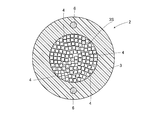
- FIG. 4 is a diagram schematically showing a structure having a cross section perpendicular to the longitudinal direction of the optical fiber cable 2 of the present embodiment.
- the same or equivalent components as those in the first embodiment are designated by the same reference numerals and duplicated description will be omitted unless otherwise specified.
- the optical fiber cable 2 of the first embodiment is the optical fiber cable 1 of the first embodiment in that a tape core wire 4 having substantially the same configuration as that of the first embodiment is housed therein. It has the same configuration as. However, the optical fiber cable 2 is mainly different from the optical fiber cable 1 in the following points.
- the optical fiber cable 1 is a tape slot type cable (RSCC) as described above.
- the optical fiber cable 2 of the present embodiment does not have the holding body 5. That is, the optical fiber cable 2 is a so-called small-diameter high-density cable (UHDC: Ultra-High Density Cable) in which the tape core wire is not accommodated in the slot of the holder but is directly accommodated in the sheath. That is, an accommodation space 3S is formed inside the sheath 3 of the optical fiber cable 2, and a plurality of tape core wires 4 are arranged in the accommodation space 3S.
- the tensile strength body 6 may be embedded in the sheath 3 of the optical fiber cable 2 at positions facing each other with the center of the optical fiber cable 2 interposed therebetween.
- the tape core wire 4 of the present embodiment has substantially the same configuration as the tape core wire 4 of the first embodiment.
- the value of the microbend loss characteristic factor F ⁇ BL_G ⁇ of the optical fiber 10 included in the tape core wire 4 of the present embodiment is 4.1 ([GPa -1 ⁇ ⁇ m ⁇ 2.5 / rad 8 ] for the reason described later. ] ⁇ 10-12 ) The following.
- the tape core wires 4 are densely arranged in the accommodation space 3S of the sheath 3. Can be done. Therefore, a large number of tape core wires can be accommodated as compared with a tape slot type cable such as the optical fiber cable 1.
- the small-diameter high-density cable since many tape core wires are densely arranged in one place as described above, a large lateral pressure tends to be applied to the optical fiber as compared with the tape slot type cable. Therefore, it is recommended to use an optical fiber having a smaller microbend loss than the optical fiber used for the tape slot type cable in the small diameter high density cable. From this point of view, the small-diameter high-density cable has a required characteristic that the value of the sandpaper tension winding loss increase is 0.34 dB / km or less.
- the present inventor calculated the value of the microbend loss characteristic factor F ⁇ BL_G ⁇ corresponding to the value of the increase in sandpaper tension winding loss (0.34 dB / km) based on the above equations (3) to (5). As a result, it was found that the value was 4.1 ([GPa -1 ⁇ ⁇ m ⁇ 2.5 / rad 8 ] ⁇ 10-12). That is, by setting the value of the microbend loss characteristic factor F ⁇ BL_G ⁇ to 4.1 ([GPa -1 ⁇ ⁇ m- 2.5 / rad 8 ] ⁇ 10-12 ) or less, the required characteristics of the small-diameter high-density cable can be obtained. It was found that the microbend loss can be suppressed to the extent that it is satisfied.
- the optical fiber 10 of the present embodiment has a microbend loss characteristic factor F ⁇ BL_G ⁇ of 4.1 ([GPa -1 ⁇ ⁇ m ⁇ 2.5 / rad 8 ] ⁇ 10-12 ) or less.
- F ⁇ BL_G ⁇ 4.1 ([GPa -1 ⁇ ⁇ m ⁇ 2.5 / rad 8 ] ⁇ 10-12 ) or less.
- the various parameters are adjusted and configured. Therefore, the microbend loss can be suppressed to the extent that the required characteristics of the small-diameter high-density cable are satisfied. Therefore, the optical fiber cable 2 using the optical fiber 10 can exhibit good optical characteristics.
- the optical fiber 10 of the present embodiment the outer diameter d f of the glass portion 13 or smaller than 125 [mu] m, the optical fiber 10 the coating thickness t to or less than 60 ⁇ m fine Even when the diameter is increased, the microbend loss can be suppressed to the extent that the required characteristics of the small diameter high density cable are satisfied. Therefore, by using the optical fiber 10 having a reduced diameter in this way, it is possible to construct a small-diameter high-density cable having excellent optical characteristics that realizes an increase in the number of cores and a reduction in size.
- the present inventor performed the following Examples 1 to 48 in order to verify the relationship between the value of the microbend loss characteristic factor F ⁇ BL_G ⁇ and the value of the sandpaper tension winding loss increase ⁇ BL.
- the embodiment of the present invention is not limited to Examples 1 to 48.
- the present inventor prepares optical fiber samples 1 to 22 in which the above-mentioned various parameters are changed, measures the value of sandpaper tension winding loss increase for each sample 1 to 22, and the above equations (3) to (3).
- the value of the microbend loss characteristic factor F ⁇ BL_G ⁇ was calculated based on (5).
- the optical fiber of sample 1 is the optical fiber of Example 1
- the optical fiber of sample 2 is the optical fiber of Example 2.
- the sample numbers of the optical fibers correspond to the numbers of the examples.
- the optical fiber of sample 8 is an optical fiber generally used for an optical fiber cable constituting a communication infrastructure, and has an outer diameter of a glass portion of 125 ⁇ m and a coating thickness of 57.5 ⁇ m. An optical fiber such as this sample 8 is sometimes referred to as a "general optical fiber".
- the sandpaper tension winding loss increase test was performed as follows. That is, first, sandpaper (SiC having an average particle diameter of 50 ⁇ m (for example, model number # 360)) is wound around the body of a bobbin having a body diameter of 380 mm, and one layer of an optical fiber wire is wound around the bobbin at 100 gf. Propagates light with a wavelength of 1550 nm. The transmission loss at this time is measured. After that, the optical fiber wire is unwound from the bobbin, light having a wavelength of 1550 nm is propagated with almost no tension applied, and the transmission loss is measured. Then, the difference between these transmission losses was obtained, and the value of this difference was defined as the sandpaper tension winding loss increase ⁇ ⁇ BL .
- Tables 1 to 5 below show the parameter specifications for each of the samples 1 to 22, the value of the microbend loss characteristic factor F ⁇ BL_G ⁇ for each of the samples 1 to 22, and the increase in sandpaper tension winding loss for each of the samples 1 to 22.
- the value of ⁇ ⁇ BL is shown.
- the mode field diameter is the mode field diameter of the LP01 mode light when the light having a wavelength of 1310 nm is propagated through the optical fiber.
- the mode field diameter is determined by the ITU-T recommendation G.I. In 650.1, it is represented by the definition formula of Petermann II (the following formula (6)).
- E (r) represents the electric field strength at the point where the distance from the central axis of the optical fiber is r.
- the cutoff wavelength indicates the minimum wavelength at which the higher-order mode is sufficiently attenuated.
- This higher-order mode refers to, for example, the LP11 mode. Specifically, it is the minimum wavelength at which the loss in the higher-order mode is 19.3 dB.
- the cutoff wavelength includes a fiber cutoff wavelength and a cable cutoff wavelength.
- the ITU-T recommendation G.I. It can be measured by the measuring method described in 650.
- the cutoff wavelengths shown in Tables 1 to 5 are cable cutoff wavelengths.
- the MAC value is the ratio of the mode field diameter of light having a wavelength of 1310 nm to the cable cutoff wavelength.
- the mode field diameter is 2w and the cable cutoff wavelength is ⁇ cc , it is defined as 2w / ⁇ cc.
- the macro bend loss is a bending loss caused by light having a wavelength of 1625 nm propagating through the bent portion when the optical fiber is bent with a radius of 10 mm. “/ Turn” in the unit of macrobend loss means “per turn of optical fiber”.
- the propagation constant difference is the difference between the propagation constant of light having a wavelength of 1550 nm in the waveguide mode and the propagation constant of light having a wavelength of 1550 nm in the radiation mode. In this experiment, the propagation constant of light having a wavelength of 1550 nm in LP01 mode.
- the propagation constant is based on the refractive index distribution of the prototype optical fiber, and is based on Non-Patent Document 7 (K. Saitoh and M. Koshiba, “Full-Vectorial Imaginary-Distance Beam Propagation Method Based on a Finite Element Scheme: Application to Photonic Crystal). It was calculated using the two-dimensional finite element method described in Fibers, ”IEEE J. Quant. Elect. Vol. 38, pp. 9 27-933, 2002.).
- the zero dispersion wavelength refers to a wavelength at which the value of the wavelength dispersion becomes zero.
- the wavelength dispersion is the sum of the material dispersion and the waveguide dispersion.
- the zero dispersion slope refers to the rate of change of wavelength dispersion with respect to the wavelength at the zero dispersion wavelength.
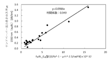
- the present inventor has a coordinate system in which the value of the microbend loss characteristic factor F ⁇ BL_G ⁇ is on the horizontal axis (X-axis) and the value of sandpaper tension winding loss increase ⁇ BL is on the vertical axis (Y-axis).
- the values of each of the 22 microbend loss characteristic factors F ⁇ BL_G ⁇ and the sandpaper tension winding loss increase ⁇ ⁇ BL were plotted. As a result, a scatter plot as shown in FIG. 5 was obtained.
- a linear function having a positive slope represented by the following equation (7) was obtained.
- the correlation coefficient of the data of FIG. 5 was 94% or more.
- the value of the microbend loss characteristic factor F ⁇ BL_G ⁇ and the value of the sandpaper tension winding loss increase ⁇ BL have a high correlation.
- the value of the microbend loss characteristic factor F ⁇ BL_G ⁇ is the sandpaper tension winding. It was found that there is a proportional relationship with the value of loss increase ⁇ ⁇ BL, which has a generally positive slope.
- the tape slot type cable has a required characteristic that the value of the sandpaper tension winding loss increase ⁇ ⁇ BL is 0.60 (dm / km) or less.
- the small-diameter high-density cable has a required characteristic that the value of the sandpaper tension winding loss increase ⁇ ⁇ BL is 0.34 (dm / km) or less. Therefore, Table 6 below shows the values of the microbend loss characteristic factor F ⁇ BL_G ⁇ , the value of the sandpaper tension winding loss increase ⁇ BL , the pass / fail of the required characteristics of the tape slot type cable (RSCC), and the small diameter in each of Examples 1 to 22. Shows pass / fail for the required characteristics of high-density cable (UHDC). In Table 6, Y means that the required characteristics are satisfied, and N means that the required characteristics are not satisfied.
- the sandpaper tension winding loss increase ⁇ ⁇ BL If the value of the microbend loss characteristic factor F ⁇ BL_G ⁇ is 4.1 ([GPa -1 ⁇ ⁇ m -2.5 / rad 8 ] ⁇ 10-12 ) or less, the sandpaper tension winding loss increase ⁇ ⁇ BL When the value becomes about 0.34 or less and the value of the microbend loss characteristic factor F ⁇ BL_G ⁇ becomes larger than 4.1 ([GPa -1 ⁇ ⁇ m ⁇ 2.5 / rad 8 ] ⁇ 10-12 ), the sandpaper It was found that the value of the tension winding loss increase ⁇ ⁇ BL tended to exceed 0.34.
- the samples satisfying the required characteristics of the tape slot type cable were the samples excluding the samples 1, 5, and 6. Further, the samples satisfying the required characteristics of the small-diameter high-density cable in addition to the required characteristics of the tape slot type cable were the samples excluding Examples 1, 2, 5, 6, 13, and 18.
- the samples other than Samples 4, 7, and 8 are smaller than the outer diameter (125 ⁇ m) of the glass portion of a general optical fiber. It has an outer diameter of 80 ⁇ m or 90 ⁇ m glass part.
- Samples 2, 3, 9 to 14, and 18 to 22 have an outer diameter of a glass portion of 80 ⁇ m
- Samples 15 to 17 have an outer diameter of a glass portion of 90 ⁇ m. That is, by adjusting the parameters as in Samples 2, 3, and 9 to 22, light that at least satisfies the required characteristics of the tape slot type cable and has an outer diameter of the glass portion smaller than that of a general optical fiber. It has been found that fibers can be formed.
- Samples 1 to 22 have a coating thickness smaller than the coating thickness of a general optical fiber (approximately 60 ⁇ m) except for Sample 8. It was. Specifically, Samples 3, 9, and 12 have a coating thickness of 42.0 ⁇ m, and Samples 10, 11, 13, 14, 18, and 20-22 have a coating thickness of 36.5 ⁇ m. It was found that Sample 2 had a coating thickness of 36.0 ⁇ m, Samples 15 to 17 had a coating thickness of 34.5 ⁇ m, and Samples 4 and 7 had a coating thickness of 34.0 ⁇ m.
- the samples other than the samples 1, 5, 6 and 8 satisfy at least the required characteristics of the tape slot type cable and are outside the glass portion smaller than the general optical fiber. It was found to have a diameter and a coating thickness. By forming both the outer diameter and the coating thickness of the glass portion to be smaller than the outer diameter and the coating thickness of the glass portion of a general optical fiber, it is possible to effectively reduce the diameter of the optical fiber.
- the optical fibers of Samples 1 to 22 have an MFD of 7.6 ⁇ m or more. If the MFD is too small, a mismatch of the MFD when connected to a general-purpose optical fiber may occur. However, if the MFD of the optical fiber is 7.6 ⁇ m or more, the mismatch of the MFD when connected to the general-purpose optical fiber can be reduced. Therefore, the occurrence of connection loss can be effectively suppressed.
- the optical fibers of Samples 5 to 8 satisfy the international standard ITU-. G.657.A1. That is, the MFD having a wavelength of 1310 nm is 8.2 ⁇ m or more and 9.6 ⁇ m or less, the cable cutoff wavelength is 1260 nm or less, the zero dispersion wavelength is 1300 nm or more and 1324 nm or less, and the zero dispersion slope is 0.073 ps / km / nm. It is 0.092 ps / km / nm or less, and the macrobend loss at a wavelength of 1625 nm when bent at a radius of 10 mm is 1.5 dB / turn or less.
- the optical fibers of Samples 1 to 4 satisfy ITU-T.G.657.A2. That is, the MFD having a wavelength of 1310 nm is 8.2 ⁇ m or more and 9.6 ⁇ m or less, the cable cutoff wavelength is 1260 nm or less, the zero dispersion wavelength is 1300 nm or more and 1324 nm or less, and the zero dispersion slope is 0.073 ps / km / nm. It is 0.092 ps / km / nm or less, and the macrobend loss at a wavelength of 1625 nm when bent at a radius of 10 mm is 0.2 dB / turn or less.
- the optical fibers of Samples 13 to 15 satisfy ITU-T.G.657.B3. That is, the MFD having a wavelength of 1310 nm is 8.26 ⁇ m or more and 9.6 ⁇ m or less, the cable cutoff wavelength is 1260 nm or less, the zero dispersion wavelength is 1300 nm or more and 1324 nm, and the zero dispersion slope is 0.073 ps / km / nm or more. It is 0.092 ps / km / nm or less, and the macrobend loss at a wavelength of 1625 nm when bent at a radius of 10 mm is 0.1 dB / turn or less.
- Example 23 to 28 the present inventor has the same optical characteristics as the samples 16, 17, and 19, specifically, the same MFD, cable cutoff wavelength, MAC value, macrobend loss (bending loss), and propagation constant as those of these samples. Assuming an optical fiber having a difference, a zero dispersion wavelength, and a zero dispersion slope, having the same primary coating layer thickness and secondary coating layer thickness as sample 19, and having an outer diameter of a glass portion of 65 ⁇ m. , The value of the microbend loss characteristic factor F ⁇ BL_G ⁇ of the optical fiber samples 23 to 28 prepared as shown in Table 7 below was determined.
- each of the samples 23 to 28 has an outer diameter of a glass portion of 65 ⁇ m and a coating thickness of 42 ⁇ m.
- the values of the microbend loss characteristic factor F ⁇ BL_G ⁇ of samples 25 to 28 are all 6.1 ([GPa -1 ⁇ ⁇ m -2.5 / rad 8 ] ⁇ 10-12 ) or less, and samples 25 to 28 are tapes. It was found that the required characteristics of the slot type cable were satisfied.
- the values of the microbend loss characteristic factor F ⁇ BL_G ⁇ of the samples 27 and 28 are 4.1 ([GPa -1 ⁇ ⁇ m ⁇ 2.5 / rad 8 ] ⁇ 10-12 ) or less, and the samples 27 and 28 are tapes.
- the required characteristics of the small diameter high density cable were satisfied. Similar to the samples 25 to 28, the samples 23 and 24 have an outer diameter of the glass portion of 65 ⁇ m and a coating layer thickness of 42 ⁇ m, but the value of the microbend loss characteristic factor F ⁇ BL_G ⁇ is 6.1 ([[ GPa -1 ⁇ ⁇ m -2.5 / rad 8 ] ⁇ 10-12 ) was exceeded, and neither the required characteristics of the tape slot type cable nor the required characteristics of the small diameter high density cable were satisfied.
- Example 29 to 36 Further, the present inventor has the same optical characteristics as the samples 15, 16, 17, and 19, specifically, the same MFD, cable cutoff wavelength, MAC value, macro bend loss, and propagation constant difference as those samples.
- the table assumes an optical fiber having a zero dispersion wavelength and a zero dispersion slope, having the same primary coating layer thickness and secondary coating layer thickness as sample 19, and having an outer diameter of 70 ⁇ m in the glass portion.
- the values of the microbend loss characteristic factor F ⁇ BL_G ⁇ of the optical fiber samples 29 to 36 adjusted as shown in 8 and 9 were determined.
- each of the samples 29 to 36 has an outer diameter of a glass portion of 70 ⁇ m and a coating thickness of 42 ⁇ m.
- the values of the microbend loss characteristic factor F ⁇ BL_G ⁇ of samples 26 to 28 are all 6.1 ([GPa -1 ⁇ ⁇ m -2.5 / rad 8 ] ⁇ 10-12 ) or less, and samples 29 to 36 are tapes. It was found that the required characteristics of the slot type cable were satisfied.
- the values of the microbend loss characteristic factor F ⁇ BL_G ⁇ of samples 31, 33, 35 and 36 are all 4.1 ([GPa -1 ⁇ ⁇ m -2.5 / rad 8 ] ⁇ 10-12 ) or less. It was found that the samples 31, 33, 35 and 36 satisfy the required characteristics of the small diameter high density cable in addition to the required characteristics of the tape slot type cable.
- the present inventor has the same optical characteristics as the samples 15, 17, and 19, specifically, the same MFD, cable cutoff wavelength, MAC value, macrobend loss, propagation constant difference, and zero dispersion as those of these samples.
- the following table assumes an optical fiber having a wavelength and a zero dispersion slope, the same primary coating layer thickness and secondary coating layer thickness as sample 19, and an outer diameter of the glass portion of 75 ⁇ m.
- the value of the microbend loss characteristic factor F ⁇ BL_G ⁇ of the optical fiber samples 37 to 42 adjusted as shown in 10 was determined.
- each of the samples 37 to 42 has an outer diameter of a glass portion of 75 ⁇ m and a coating thickness of 42 ⁇ m.
- the values of the microbend loss characteristic factor F ⁇ BL_G ⁇ of samples 37 to 42 are all 4.1 ([GPa -1 ⁇ ⁇ m -2.5 / rad 8 ] ⁇ 10-12 ) or less, and samples 37 to 42 are tapes. It was found that in addition to the required characteristics of the slot type cable, the required characteristics of the small diameter high density cable were satisfied.
- Example 43 to 48 the present inventor has the same optical characteristics as the samples 15, 17, and 19, specifically, the same MFD, cable cutoff wavelength, MAC value, macrobend loss, propagation constant difference, and zero dispersion as those of these samples.
- the following table assumes an optical fiber having a wavelength and a zero dispersion slope, the same primary coating layer thickness and secondary coating layer thickness as sample 19, and an outer diameter of a glass portion of 80 ⁇ m.
- the value of the microbend loss characteristic factor F ⁇ BL_G ⁇ of the optical fiber samples 43 to 48 adjusted as shown in No. 11 was determined.
- each of the samples 45 to 48 has an outer diameter of the glass portion of 80 ⁇ m, an outer diameter of the secondary coating layer of 125 ⁇ m, and a thickness of the coating layer of 22.5 ⁇ m.
- the values of the microbend loss characteristic factor F ⁇ BL_G ⁇ of samples 45 to 48 are all 6.1 ([GPa -1 ⁇ ⁇ m -2.5 / rad 8 ] ⁇ 10-12 ) or less, and samples 45 to 48 are tapes. It was found that the required characteristics of the slot type cable were satisfied.
- the value of the microbend loss characteristic factor F ⁇ BL_G ⁇ of sample 47 is 4.1 ([GPa -1 ⁇ ⁇ m ⁇ 2.5 / rad 8 ] ⁇ 10-12 ) or less, and sample 47 is of a tape slot type cable. In addition to the required characteristics, it was found to meet the required characteristics of the small diameter high density cable. Similar to the samples 45 to 48, the samples 43 and 44 have an outer diameter of the glass portion of 80 ⁇ m, an outer diameter of the secondary coating layer of 125 ⁇ m, and a thickness of the coating layer of 22.5 ⁇ m, but microbend.
- the value of the loss characteristic factor F ⁇ BL_G ⁇ exceeds 6.1 ([GPa -1 ⁇ ⁇ m -2.5 / rad 8 ] ⁇ 10-12 ), and the required characteristics of the tape slot type cable are also those of the small diameter high density cable. It also did not meet the required characteristics.
- the secondary coating layer is the outermost layer of the optical fiber.
- the secondary coating layer and the colored layer are used as long as the Young's modulus of the colored layer is not significantly different from the Young's modulus of the secondary coating layer. It is possible to apply it to the present invention by regarding it as a second coating layer, that is, a secondary coating layer.
- an optical fiber capable of suppressing microbend loss is provided, and can be used in a field such as a communication infrastructure.
Landscapes
- Physics & Mathematics (AREA)
- General Physics & Mathematics (AREA)
- Optics & Photonics (AREA)
- Chemical & Material Sciences (AREA)
- Life Sciences & Earth Sciences (AREA)
- Engineering & Computer Science (AREA)
- General Life Sciences & Earth Sciences (AREA)
- Chemical Kinetics & Catalysis (AREA)
- General Chemical & Material Sciences (AREA)
- Geochemistry & Mineralogy (AREA)
- Materials Engineering (AREA)
- Organic Chemistry (AREA)
- Optical Fibers, Optical Fiber Cores, And Optical Fiber Bundles (AREA)
Priority Applications (6)
| Application Number | Priority Date | Filing Date | Title |
|---|---|---|---|
| CN202080006055.7A CN113099725B (zh) | 2019-11-08 | 2020-11-06 | 光纤 |
| US17/297,716 US11860406B2 (en) | 2019-11-08 | 2020-11-06 | Optical fiber |
| EP20883675.9A EP3869252A4 (en) | 2019-11-08 | 2020-11-06 | OPTICAL FIBER |
| JP2021513356A JPWO2021090913A1 (ja) | 2019-11-08 | 2020-11-06 | 光ファイバ |
| JP2022069510A JP7403574B2 (ja) | 2019-11-08 | 2022-04-20 | 光ファイバ |
| US17/743,884 US11808972B2 (en) | 2019-11-08 | 2022-05-13 | Optical fiber |
Applications Claiming Priority (2)
| Application Number | Priority Date | Filing Date | Title |
|---|---|---|---|
| JP2019-203556 | 2019-11-08 | ||
| JP2019203556 | 2019-11-08 |
Related Child Applications (2)
| Application Number | Title | Priority Date | Filing Date |
|---|---|---|---|
| US17/297,716 A-371-Of-International US11860406B2 (en) | 2019-11-08 | 2020-11-06 | Optical fiber |
| US17/743,884 Continuation-In-Part US11808972B2 (en) | 2019-11-08 | 2022-05-13 | Optical fiber |
Publications (1)
| Publication Number | Publication Date |
|---|---|
| WO2021090913A1 true WO2021090913A1 (ja) | 2021-05-14 |
Family
ID=75849163
Family Applications (1)
| Application Number | Title | Priority Date | Filing Date |
|---|---|---|---|
| PCT/JP2020/041539 Ceased WO2021090913A1 (ja) | 2019-11-08 | 2020-11-06 | 光ファイバ |
Country Status (5)
| Country | Link |
|---|---|
| US (1) | US11860406B2 (https=) |
| EP (1) | EP3869252A4 (https=) |
| JP (2) | JPWO2021090913A1 (https=) |
| CN (1) | CN113099725B (https=) |
| WO (1) | WO2021090913A1 (https=) |
Cited By (3)
| Publication number | Priority date | Publication date | Assignee | Title |
|---|---|---|---|---|
| JPWO2022085244A1 (https=) * | 2020-10-19 | 2022-04-28 | ||
| JP2022101633A (ja) * | 2019-11-08 | 2022-07-06 | 株式会社フジクラ | 光ファイバ |
| US11808972B2 (en) | 2019-11-08 | 2023-11-07 | Fujikura Ltd. | Optical fiber |
Citations (5)
| Publication number | Priority date | Publication date | Assignee | Title |
|---|---|---|---|---|
| US20040042750A1 (en) * | 2002-08-09 | 2004-03-04 | Gillberg Gunilla E. | Clay nanocomposite optical fiber coating |
| JP2008203495A (ja) * | 2007-02-20 | 2008-09-04 | Kyocera Mita Corp | 画像形成装置 |
| JP2012508395A (ja) | 2008-11-07 | 2012-04-05 | ドラカ・コムテツク・ベー・ベー | 小径光ファイバ |
| CN104503020A (zh) * | 2014-12-19 | 2015-04-08 | 华中科技大学 | 一种纵向螺旋模式转移光纤 |
| JP2018081328A (ja) * | 2016-04-01 | 2018-05-24 | 株式会社フジクラ | 光ファイバ |
Family Cites Families (18)
| Publication number | Priority date | Publication date | Assignee | Title |
|---|---|---|---|---|
| US4105284A (en) * | 1976-05-10 | 1978-08-08 | Corning Glass Works | Buffered optical waveguide fiber |
| JP2008203496A (ja) * | 2007-02-20 | 2008-09-04 | Fujikura Ltd | ダブルコアファイバ、これを用いた光結合デバイス、信号光励起光結合デバイス、ファイバアンプ及びファイバレーザ |
| US8467650B2 (en) * | 2007-11-09 | 2013-06-18 | Draka Comteq, B.V. | High-fiber-density optical-fiber cable |
| DK2581770T3 (da) | 2008-02-22 | 2014-06-30 | Sumitomo Electric Industries | Optisk fiber og optisk kabel |
| US20110188822A1 (en) | 2010-02-04 | 2011-08-04 | Ofs Fitel, Llc | Optical fiber coatings for reducing microbend losses |
| ES2539824T3 (es) * | 2010-03-17 | 2015-07-06 | Draka Comteq B.V. | Fibra óptica de modo único con reducidas pérdidas por curvatura |
| JP5790942B2 (ja) * | 2012-06-22 | 2015-10-07 | 住友電気工業株式会社 | 光ファイバ素線 |
| JP6273847B2 (ja) | 2014-01-09 | 2018-02-07 | 住友電気工業株式会社 | 光ファイバおよび光ケーブル |
| WO2018022031A1 (en) * | 2016-07-27 | 2018-02-01 | Prysmian S.P.A. | Flexible optical-fiber ribbon |
| CN109562989B (zh) | 2016-08-02 | 2021-10-26 | 住友电气工业株式会社 | 光纤以及光纤的制造方法 |
| JP7214352B2 (ja) | 2018-03-08 | 2023-01-30 | 古河電気工業株式会社 | 光ファイバ |
| JP7384827B2 (ja) | 2018-04-30 | 2023-11-21 | コーニング インコーポレイテッド | 小径の低減衰光ファイバ |
| WO2019212800A1 (en) | 2018-04-30 | 2019-11-07 | Corning Incorporated | Small outer diameter low attenuation optical fiber |
| US11181686B2 (en) | 2018-04-30 | 2021-11-23 | Corning Incorporated | Small diameter low attenuation optical fiber |
| US11808972B2 (en) * | 2019-11-08 | 2023-11-07 | Fujikura Ltd. | Optical fiber |
| CN113099726B (zh) * | 2019-11-08 | 2023-08-04 | 株式会社藤仓 | 光纤 |
| US11803007B2 (en) * | 2019-11-08 | 2023-10-31 | Fujikura Ltd. | Optical fiber |
| JPWO2021090913A1 (ja) | 2019-11-08 | 2021-11-25 | 株式会社フジクラ | 光ファイバ |
-
2020
- 2020-11-06 JP JP2021513356A patent/JPWO2021090913A1/ja not_active Ceased
- 2020-11-06 CN CN202080006055.7A patent/CN113099725B/zh active Active
- 2020-11-06 EP EP20883675.9A patent/EP3869252A4/en active Pending
- 2020-11-06 WO PCT/JP2020/041539 patent/WO2021090913A1/ja not_active Ceased
- 2020-11-06 US US17/297,716 patent/US11860406B2/en active Active
-
2022
- 2022-04-20 JP JP2022069510A patent/JP7403574B2/ja active Active
Patent Citations (5)
| Publication number | Priority date | Publication date | Assignee | Title |
|---|---|---|---|---|
| US20040042750A1 (en) * | 2002-08-09 | 2004-03-04 | Gillberg Gunilla E. | Clay nanocomposite optical fiber coating |
| JP2008203495A (ja) * | 2007-02-20 | 2008-09-04 | Kyocera Mita Corp | 画像形成装置 |
| JP2012508395A (ja) | 2008-11-07 | 2012-04-05 | ドラカ・コムテツク・ベー・ベー | 小径光ファイバ |
| CN104503020A (zh) * | 2014-12-19 | 2015-04-08 | 华中科技大学 | 一种纵向螺旋模式转移光纤 |
| JP2018081328A (ja) * | 2016-04-01 | 2018-05-24 | 株式会社フジクラ | 光ファイバ |
Non-Patent Citations (8)
| Title |
|---|
| C. D. HUSSEY ET AL.: "Characterization and design of single-mode optical fibres", OPTICAL AND QUANTUM ELECTRONICS, vol. 14, no. 4, 1982, pages 347 - 358 |
| J. BALDAUF ET AL.: "Relationship of Mechanical Characteristics of Dual Coated Single Mode Optical Fibers and Microbending Loss", IEICE TRANS. COMMUN., vol. E76-B, no. 4, 1993, XP000378265 |
| K. KOBAYASHI ET AL.: "Study of Microbending loss in thin coated fibers and fiber ribbons", IWCS, 1993, pages 386 - 392 |
| K. PETERMANN ET AL.: "Upper and Lower Limits for the Microbending Loss in Arbitrary Single-Mode Fibers", J. LIGHTWAVE TECHNOLOGY, vol. 4, no. l, 7 February 1986 (1986-02-07) |
| K. SAITOHM. KOSHIBA: "Full-Vectorial Imaginary-Distance Beam Propagation Method Based on a Finite Element Scheme: Application to Photonic Crystal Fibers", IEEE J. QUANT. ELECT., vol. 38, 2002, pages 27 - 933, XP011065225 |
| OKOSHI ET AL.: "Optical Fiber", OHMSHA, 1989, pages 235 - 239 |
| P. SILLARD ET AL.: "Micro-Bend Losses of Trench-Assisted Single-Mode Fibers", ECOC2010, WE.8.F.3, 2010 |
| PETERMANN ET AL.: "Upper and Lower Limits for the Microbending Loss in Arbitrary Single-Mode Fibers", J. LIGHTWAVE TECHNOLOGY, vol. LT-4, no. l, 1986, pages 2 - 7 |
Cited By (7)
| Publication number | Priority date | Publication date | Assignee | Title |
|---|---|---|---|---|
| JP2022101633A (ja) * | 2019-11-08 | 2022-07-06 | 株式会社フジクラ | 光ファイバ |
| US11808972B2 (en) | 2019-11-08 | 2023-11-07 | Fujikura Ltd. | Optical fiber |
| JP7403574B2 (ja) | 2019-11-08 | 2023-12-22 | 株式会社フジクラ | 光ファイバ |
| US11860406B2 (en) | 2019-11-08 | 2024-01-02 | Fujikura Ltd. | Optical fiber |
| JPWO2022085244A1 (https=) * | 2020-10-19 | 2022-04-28 | ||
| WO2022085244A1 (ja) * | 2020-10-19 | 2022-04-28 | 株式会社フジクラ | 光ファイバケーブル |
| JP7499867B2 (ja) | 2020-10-19 | 2024-06-14 | 株式会社フジクラ | 光ファイバケーブル |
Also Published As
| Publication number | Publication date |
|---|---|
| JP2022101633A (ja) | 2022-07-06 |
| US20220026632A1 (en) | 2022-01-27 |
| JPWO2021090913A1 (ja) | 2021-11-25 |
| CN113099725B (zh) | 2023-08-04 |
| JP7403574B2 (ja) | 2023-12-22 |
| EP3869252A4 (en) | 2022-01-05 |
| EP3869252A1 (en) | 2021-08-25 |
| US11860406B2 (en) | 2024-01-02 |
| CN113099725A (zh) | 2021-07-09 |
Similar Documents
| Publication | Publication Date | Title |
|---|---|---|
| CN113099726B (zh) | 光纤 | |
| JP6486533B2 (ja) | 光ファイバ | |
| JP7403574B2 (ja) | 光ファイバ | |
| CN106054330B (zh) | 光缆 | |
| WO2015001990A1 (ja) | マルチコア光ファイバおよびマルチコア光ファイバケーブル | |
| KR102848777B1 (ko) | 광섬유 케이블 | |
| WO2020004230A1 (ja) | 光ファイバケーブル | |
| US11808972B2 (en) | Optical fiber | |
| US11803007B2 (en) | Optical fiber | |
| KR102848778B1 (ko) | 광섬유 케이블 | |
| CA3195858C (en) | Optical fiber cable |
Legal Events
| Date | Code | Title | Description |
|---|---|---|---|
| ENP | Entry into the national phase |
Ref document number: 2021513356 Country of ref document: JP Kind code of ref document: A |
|
| ENP | Entry into the national phase |
Ref document number: 2020883675 Country of ref document: EP Effective date: 20210517 |
|
| 121 | Ep: the epo has been informed by wipo that ep was designated in this application |
Ref document number: 20883675 Country of ref document: EP Kind code of ref document: A1 |
|
| NENP | Non-entry into the national phase |
Ref country code: DE |