WO2021090897A1 - 情報処理装置、情報処理方法及び情報処理プログラム - Google Patents
情報処理装置、情報処理方法及び情報処理プログラム Download PDFInfo
- Publication number
- WO2021090897A1 WO2021090897A1 PCT/JP2020/041428 JP2020041428W WO2021090897A1 WO 2021090897 A1 WO2021090897 A1 WO 2021090897A1 JP 2020041428 W JP2020041428 W JP 2020041428W WO 2021090897 A1 WO2021090897 A1 WO 2021090897A1
- Authority
- WO
- WIPO (PCT)
- Prior art keywords
- information
- model
- basis
- input
- unit
- Prior art date
- Legal status (The legal status is an assumption and is not a legal conclusion. Google has not performed a legal analysis and makes no representation as to the accuracy of the status listed.)
- Ceased
Links
Images





Classifications
-
- G—PHYSICS
- G06—COMPUTING OR CALCULATING; COUNTING
- G06N—COMPUTING ARRANGEMENTS BASED ON SPECIFIC COMPUTATIONAL MODELS
- G06N3/00—Computing arrangements based on biological models
- G06N3/02—Neural networks
-
- G—PHYSICS
- G08—SIGNALLING
- G08G—TRAFFIC CONTROL SYSTEMS
- G08G1/00—Traffic control systems for road vehicles
- G08G1/16—Anti-collision systems
- G08G1/166—Anti-collision systems for active traffic, e.g. moving vehicles, pedestrians, bikes
-
- G—PHYSICS
- G06—COMPUTING OR CALCULATING; COUNTING
- G06N—COMPUTING ARRANGEMENTS BASED ON SPECIFIC COMPUTATIONAL MODELS
- G06N3/00—Computing arrangements based on biological models
- G06N3/02—Neural networks
- G06N3/04—Architecture, e.g. interconnection topology
- G06N3/045—Combinations of networks
-
- B—PERFORMING OPERATIONS; TRANSPORTING
- B60—VEHICLES IN GENERAL
- B60W—CONJOINT CONTROL OF VEHICLE SUB-UNITS OF DIFFERENT TYPE OR DIFFERENT FUNCTION; CONTROL SYSTEMS SPECIALLY ADAPTED FOR HYBRID VEHICLES; ROAD VEHICLE DRIVE CONTROL SYSTEMS FOR PURPOSES NOT RELATED TO THE CONTROL OF A PARTICULAR SUB-UNIT
- B60W60/00—Drive control systems specially adapted for autonomous road vehicles
- B60W60/001—Planning or execution of driving tasks
- B60W60/0015—Planning or execution of driving tasks specially adapted for safety
- B60W60/0017—Planning or execution of driving tasks specially adapted for safety of other traffic participants
-
- G—PHYSICS
- G06—COMPUTING OR CALCULATING; COUNTING
- G06N—COMPUTING ARRANGEMENTS BASED ON SPECIFIC COMPUTATIONAL MODELS
- G06N3/00—Computing arrangements based on biological models
- G06N3/02—Neural networks
- G06N3/04—Architecture, e.g. interconnection topology
- G06N3/0464—Convolutional networks [CNN, ConvNet]
-
- G—PHYSICS
- G06—COMPUTING OR CALCULATING; COUNTING
- G06N—COMPUTING ARRANGEMENTS BASED ON SPECIFIC COMPUTATIONAL MODELS
- G06N3/00—Computing arrangements based on biological models
- G06N3/02—Neural networks
- G06N3/08—Learning methods
- G06N3/084—Backpropagation, e.g. using gradient descent
-
- G—PHYSICS
- G06—COMPUTING OR CALCULATING; COUNTING
- G06N—COMPUTING ARRANGEMENTS BASED ON SPECIFIC COMPUTATIONAL MODELS
- G06N20/00—Machine learning
- G06N20/10—Machine learning using kernel methods, e.g. support vector machines [SVM]
Definitions
- This disclosure relates to an information processing device, an information processing method, and an information processing program.
- Patent Document 1 a technique has been proposed in which when an emergency signal is received, a very necessary behavior registered in advance by the driver is activated.
- Patent Document 2 there has been proposed a technique of aggregating driving behavior data, associating it with a road network, managing and storing it in order to support automatic driving.
- the prior art provides a technique in which the computer operates very much, but does not consider how the computer judges.
- the information processing apparatus of one form according to the present disclosure includes a model having a neural network structure, an acquisition unit for acquiring input information input to the model, and an acquisition unit for the model.
- the generation unit Based on the state information indicating the state of the model after the input of the input information, the generation unit includes a generation unit for generating the basis information indicating the basis for the output of the model after the input of the input information to the model.
- Embodiment 1-1 Outline of information processing according to the embodiment of the present disclosure 1-1-1. Issues and effects in autonomous driving 1-1-2.
- Other visualization examples 1-1-2-1 Visualization analysis method by compound algorithm 1-1-3.
- AI ethics 1-2 Configuration of mobile device according to the embodiment 1-2-1.
- Model example 1-3 Information processing procedure according to the embodiment 1-4.
- Other information processing examples 1-5 Conceptual diagram of the configuration of the in-vehicle system 2.
- Embodiments 2-1 Other configuration examples 2-2. Structure of mobile body 2-3. Others 3. Effect of this disclosure 4.
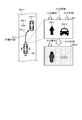
- FIG. 1 is a diagram showing an example of information processing according to the embodiment of the present disclosure.
- the information processing according to the embodiment of the present disclosure is realized by the mobile device 100 shown in FIG.
- the mobile device 100 is an information processing device that executes information processing according to the embodiment.
- the mobile device 100 is a mobile device that travels by automatic operation.
- the mobile device 100 is a mobile device that automatically travels by appropriately using various conventional techniques related to automatic driving.
- the mobile device 100 may be a vehicle that is automated at any level 0 to 5 defined in SAE (Society of Automotive Engineers).
- SAE Society of Automotive Engineers
- the mobile device 100 shows a case where the vehicle is automated at level 3. That is, in the example of FIG. 1, the mobile device 100 is a vehicle in which the mobile device 100 itself autonomously controls traveling and can be operated by a user riding on the mobile device 100 as needed. Indicates the case where.
- the mobile device 100 may be a highly automated vehicle of level 4 or higher, which does not require the driver to board, or may be level 2 or lower.
- a vehicle traveling by automatic driving a so-called automobile
- a moving body device 100 is shown as an example of a moving body, but any moving body can be used as long as it travels autonomously.
- the moving body is not limited to four wheels, but various types such as a moving body having wheels other than four such as two wheels and three wheels, a moving body having no wheels, a drone, a bot, and the like. It may be a moving body of.
- a moving body in which a person rides is shown as an example, but the moving body may be suitable in a form in which an unmanned and autonomous movement is performed without a person riding on it. To do.
- FIG. 2 is a diagram showing an example of the flow of information processing according to the embodiment.
- a user hereinafter, also referred to as “user U”
- the mobile device 100 is traveling on the road RD11.
- the direction from the mobile device 100 toward the objects OB11 and OB12, which will be described later, is in front of the mobile device 100, and the mobile device 100 is traveling forward.
- the side portion of the road RD11 is an area such as a wall surface where the mobile device 100 cannot enter.
- the mobile device 100 detects by the sensor unit 14 (see FIG.
- step S11 The mobile device 100 detects image information (also simply referred to as “image”) by the image sensor 141 (see FIG. 3). In the example of FIG. 1, the mobile device 100 detects (images) the image IM1 by the image sensor 141.
- image information also simply referred to as “image”
- the mobile device 100 detects (images) the image IM1 by the image sensor 141.
- the mobile device 100 performs the recognition process (step S12).
- the mobile device 100 performs recognition processing based on the image IM1 captured by the image sensor 141.
- the mobile device 100 performs a process of recognizing an object or the like included in the image IM1.
- the mobile device 100 performs recognition processing using the model M1 for image recognition as shown in FIG.
- the moving body device 100 inputs the image IM1 as the input information IND1 to the model M1 to cause the model M1 to output the recognition result.
- the model M1 outputs information corresponding to the input of the model M2 as a recognition result.
- the model M1 outputs information indicating the type (class) of the object included in the image and information indicating the position (area) of the object in response to the input of the image.
- the model M1 may output any information as long as it corresponds to the input of the model M2. For example, information indicating the status of the captured image such as "the signal is red”. May be output.
- the model M1 is a multi-layer neural network, and has a structure such as a deep neural network having four or more layers as shown in FIG. 6, a so-called deep neural network (deep learning). Further, the model M1 is a model that includes a CNN (Convolutional Neural Network) and outputs information indicating an object included in the image and its position in response to an image input. Model M1 is a model having a neural network structure. For example, model M1 is a model having a CNN structure having a so-called convolution layer.
- CNN Convolutional Neural Network
- the moving body device 100 indicates that the model M1 has an object OB11 of the type "human” at a position (region) on the left side of the image IM1 by inputting the image IM1 into the model M1. Output information. Further, by inputting the image IM1 into the model M1, the moving body device 100 causes the model M1 to output information indicating that the object OB12 of the type "vehicle” exists in the position (area) on the right side of the image IM1. .. Then, the mobile device 100 performs the processes of steps S13 to S16. In the example of FIG. 1, for convenience of explanation, steps S13 to S16 are added to each process, but it does not indicate that step S15 is performed after step S14. For example, the processes of steps S13 to S14 and the processes of steps S15 to S16 are performed in parallel.
- the mobile device 100 performs a generation process (step S13).
- the mobile device 100 generates basis information indicating the basis for the output of the model after the input information is input to the model, based on the state information indicating the state of the model M1 after the input information is input to the model M1.
- the mobile device 100 generates evidence information indicating the basis for the output of the model M1 after the input of the image IM1 to the model M1 based on the state information indicating the state of the model M1 after the input of the image IM1 to the model M1. To do.
- the mobile device 100 generates basis information indicating the basis for the output of the model M1 after the input of the image IM1 by the Grad-CAM (Gradient-weighted Class Activation Mapping).
- the mobile device 100 generates rationale information showing the rationale for the output of the model M1 after the input of the image IM1 by the processing related to Grad-CAM as disclosed in the following documents.
- the mobile device 100 uses the technology of Grad-CAM, which is a visualization method applicable to the entire network including CNN, to generate evidence information showing the basis for the output of the model M1 after the input of the image IM1.
- the mobile device 100 can visualize the part that affects each class by calculating the weight of each channel from the final layer of the CNN and multiplying the weights. In this way, the mobile device 100 can visualize which part of the image was focused on in the neural network including the CNN.
- the mobile device 100 generates ground information by the method of the Grad-CAM (see the above document). For example, the mobile device 100 specifies a target type (class) and generates information (image) corresponding to the specified class. For example, the mobile device 100 generates information (image) for a designated class by various processes such as backpropagation using the technology of Grad-CAM.
- the mobile device 100 specifies a class of the type "person” and generates an image related to the basis information in the basis information generation unit RSD1 (see FIG. 2) corresponding to the type "person".
- the rationale information generation unit RSD1 generates, for example, an image showing a range (area) being watched for recognition (classification) of the type "person” in the form of a so-called heat map (color map).
- heat map color map
- the basis information generation unit RSD1 is based on the image showing that the position of the human object OB11 in the image IM1 is most closely watched and the human object OB11 is recognized. Generated as information RINF1. Further, in the example of FIG. 1, it is assumed that the mobile device 100 also appropriately recognizes the object OB12 which is a vehicle.
- the mobile device 100 performs the display process (step S14).
- the mobile device 100 displays the ground information RINF1 generated by the ground information generation unit RSD1 on the display unit 11 (see FIG. 3).
- the mobile device 100 realizes visualization by the display DP related to the ground information generated by the ground information generation unit RSD1.
- the mobile device 100 can explain the rationale for the output of the model having the structure of the neural network. In this way, the mobile device 100 can explain the grounds for processing by the mobile device 100, which is an information processing device.
- the user U who rides on the mobile device 100 can grasp the basis information regarding the models M1 to M3 in real time. For example, when the user U riding on the mobile device 100 has a discrepancy between the actual state and the ground information of the ground information generation unit RSD1, the user U himself stops the automatic operation and operates the mobile device 100. It becomes possible to do.
- the human object OB11 is appropriately recognized as shown in the ground information generation unit RSD1, the user U may maintain the automatic operation state of the mobile device 100.
- the mobile device 100 stores the ground information generated in the ground information generation unit RSD1 as a history in the storage unit 12 (see FIG. 3) in association with the image IM1 which is the input information IND1 which is the base thereof.
- the mobile device 100 stores the input information IND1 and the basis information such as the basis information RINF1 in association with each other in the log information storage unit 122 (see FIG. 3). This makes it possible to verify what kind of input the mobile device 100 has determined to perform the subsequent operation.
- step S15 is performed as soon as the process of step S12 is completed.
- the mobile device 100 performs a prediction process based on the recognition result of the recognition process (step S15).
- the mobile device 100 performs prediction processing based on the output of the model M1.
- the mobile device 100 performs a process of predicting an action (movement mode) such as movement of an object included in the image IM1.
- the mobile device 100 performs prediction processing using the prediction model M2 as shown in FIG.
- the mobile device 100 causes the model M2 to output the prediction result by inputting the information (recognition result information) output by the model M1 into the model M2.
- the model M2 outputs information indicating the moving direction and speed of the object included in the recognition result information in response to the input of the recognition result information.
- the model M2 is a multi-layer neural network, and has a structure such as a deep neural network having four or more layers as shown in FIG. 6, a so-called deep neural network (deep learning).
- the model M2 is not limited to the information output by the model M1, and may perform prediction processing by inputting various information such as sensor information.
- the mobile device 100 predicts the motion mode of the human object OB11.
- the mobile device 100 predicts the moving direction and speed of the object OB11. In the example of FIG. 1, the mobile device 100 predicts that the object OB 11 is moving toward the mobile device 100.
- the moving body device 100 predicts the motion mode of the object OB12 which is a vehicle.
- the mobile device 100 predicts the moving direction and speed of the object OB12. In the example of FIG. 1, the mobile device 100 predicts that the object OB 12 is moving toward the mobile device 100.
- the mobile device 100 performs a process of determining an action plan based on the prediction result of the prediction process (step S16).
- the mobile device 100 performs a process of generating an action plan based on the output of the model M2.
- the mobile device 100 determines an action plan based on the predicted motion mode of the object OB11 and the object OB12.
- the mobile device 100 uses the model M3 for the action plan as shown in FIG. 2 to perform a process of determining the action plan.
- the mobile device 100 causes the model M3 to output an action plan by inputting the information (prediction result information) output by the model M2 into the model M3.
- the model M3 outputs information indicating the action plan of the mobile device 100 in response to the input of the prediction result information.
- the model M3 is a multi-layer neural network, and has a structure such as a deep neural network having four or more layers as shown in FIG. 6, a so-called deep neural network (deep learning).
- the model M3 is not limited to the information output by the model M2, and may perform a process of generating an action plan by inputting various information such as sensor information.
- the mobile device 100 is an information processing device that performs actions with models M1 to M3, which are models learned by machine learning (machine learning model).
- the action referred to here includes various actions such as information processing executed by the information processing device and actions by a robot, a moving body, or the like.
- the objects OB11 and OB12 are located in the traveling direction of the moving body device 100 and are approaching the moving body device 100, and both the objects OB11 and OB12 cannot be avoided.
- Determine an action plan to avoid Specifically, the mobile device 100 plans a path PP11 traveling to the right in the traveling direction in order to avoid a collision with the object OB11 located on the left side in the traveling direction.
- the mobile device 100 generates action plan information indicating the route PP11. Then, the mobile device 100 controls the automatic operation based on the action plan information indicating the route PP11.
- the mobile device 100 stores the input information IND1 in association with the travel information of the actual mobile device 100 based on the route PP11 and the route PP11 in the log information storage unit 122 (see FIG. 3). This makes it possible for the mobile device 100 to verify what kind of input the mobile device 100 has made and what kind of plan the mobile device 100 has traveled.
- the moving body device 100 detects (recognizes) the pedestrian object OB11 by the image IM1 detected by the image sensor 141, and is a heat map in which the object OB11 is highlighted.
- the rationale information generated by the rationale information generation unit RSD1 is displayed on the display unit 11.
- the pedestrian is detected from the sensor in the automatic driving, and the pedestrian is highlighted by the heat map by the visualization display device (for example, the display unit 11 or the like).
- the mobile device 100 takes a course toward the object OB12, which is a vehicle, and approaches the object OB12 in order to avoid the object OB11, which is a pedestrian.
- the mobile device 100 displays the ground information in real time, which is the heat map in which the pedestrian object OB11 is highlighted.
- the passenger of the mobile device 100 can recognize that the mobile device 100 is taking a course toward the vehicle in order to avoid a person.
- the passenger of the mobile device 100 can see that the mobile device 100 traveling by automatic driving is trying to avoid pedestrians. Therefore, the occupant of the mobile device 100 can avoid an accident with an oncoming vehicle by switching to the emergency manual operation, stopping the automatic operation, and operating the steering wheel portion and the brake portion by himself / herself. it can.
- the moving body device 100 collides with the oncoming object OB12 because the automatic driving determines that the moving body device 100 moves to the right in order to avoid the pedestrian who is the object OB11. Even in such a case, the moving body device 100 stores the ground information generated by the ground information generation unit RSD1 which is a heat map highlighting the pedestrian object OB11 in the storage unit 12. Therefore, it is possible to provide information indicating the reason (rationale) that the collision with the object OB12 is to avoid the object OB11 which is a pedestrian.
- various information recorded by the sensor unit 14 for example, the speed and acceleration of the mobile device 100, the ambient outside temperature, the road surface condition (wetting by rain, freezing, etc.), and the physical condition (awareness) of the driver in the company. It is also possible to provide sensor information such as presence / absence, blood pressure, body temperature, heart rate, posture, etc.).
- the mobile device 100 uses sensor information such as speed, acceleration, ambient outside temperature, road surface condition, and physical condition of a driver in the company detected by the sensor unit 14, and information indicating the basis of the action of the mobile device 100. It may be output as. That is, it can be proved from the log data that the mobile device 100 comprehensively considers this information and is for avoiding pedestrians as an explanation of the collision accident with the oncoming vehicle.
- the mobile device 100 includes a rationale information generation unit RSD1 having a plurality of rationale generation algorithms for generating rationale information for an action.
- the basis information generation unit RSD1 corresponds to the generation unit 136 in FIG. 3, the storage unit 12 in which a plurality of basis generation algorithms are stored, and the like.
- the storage unit 12 stores a plurality of computer programs (also simply referred to as “programs”) in which each of the plurality of basis generation algorithms is implemented. In this way, a program in which an algorithm is implemented may be described as an algorithm.
- the plurality of basis generation algorithms referred to here include algorithms using methods such as Grad-CAM, LIMIT (Local Interpretable Model-agnostic Explanations), and TCAV (Testing with Concept Activation Vectors), which will be described later.
- the plurality of rationale generation algorithms include three algorithms: an algorithm based on the Grad-CAM method, an algorithm based on the LIMIT method, and an algorithm based on the TCAV method.
- the basis generation algorithm is not limited to Grad-CAM, LIMIT, and TCAV, and may be an algorithm using various methods.
- the mobile device 100 generates the basis information of the action by using one of the basis generation algorithms among the plurality of basis generation algorithms.
- the mobile device 100 selects one of the rationale generation algorithms among the plurality of rationale generation algorithms, and generates the rationale information of the action using the selected rationale generation algorithm.
- the mobile device 100 selects an algorithm based on the Grad-CAM method from among a plurality of basis generation algorithms, and takes an action using the algorithm based on the selected Grad-CAM method. Generate rationale information for.
- the mobile device 100 wants to obtain a locally approximated basis, it selects an algorithm based on the LIMIT method and generates the basis information of the action using the algorithm based on the selected LIMIT method.
- the mobile device 100 wants to add a direction for validating the concept, it selects an algorithm based on the TCAV method and generates ground information for the action using the algorithm based on the selected TCAV method.
- the mobile device 100 outputs information indicating the basis of the action based on the basis information generated based on one or more basis generation algorithms and / or the sensor information.
- the mobile device 100 has a first rationale information generated by an algorithm based on the Grad-CAM method, a second rationale information generated by an algorithm based on the LIMIT method, and a first rationale information generated by an algorithm based on the TCAV method.
- 3 Output the basis information as information indicating the basis of the action.
- the mobile device 100 outputs the basis information of the action generated by using the selected basis generation algorithm.
- the mobile device 100 selects an algorithm based on the Grad-CAM method and outputs the basis information of the action generated by using the algorithm based on the selected Grad-CAM method. To do.
- the mobile device 100 has a stop function.
- the mobile device 100 detects an abnormality and executes an emergency switch from automatic operation to manual operation.
- the concept of stopping AI for automatic driving is very important.
- the AI itself detects an abnormality and switches from automatic driving to manual driving for humans (passengers, etc.). To request. Then, by specifically visualizing what is the problem, the mobile device 100 can prevent an accident by paying attention to a part to be watched by a human being.
- Such a mobile device 100 corresponds to a system in which the AI pushes the emergency stop button by itself and the AI explains what is the problem by visualization.
- the mobile device 100 uses a model (neural network) learned by using the data of the area where the mobile device 100 is used (operated) as a learning data set. For example, the situation in Japan and the United States is different. Therefore, when the mobile device 100 is run in Japan, a network that collects and learns data in Japan is used for the mobile device 100. As a result, the mobile device 100 can realize automatic driving that appropriately copes with the situation where the left side traffic and the road in Japan are narrow. For example, if datasets from different regions are used, a network will be created based on unfavorable data such as learning data for right-hand traffic and data with different traffic rules for right-turn and left-turn.
- the mobile device 100 depending on the area where the mobile device 100 is used, it is possible to use a model trained using a data set optimal for that area. An appropriate model corresponding to the usage situation of the mobile device 100 can be used. Then, it can be explained that the learning data used for learning the model used in the mobile device 100 is the data corresponding to an appropriate environment.
- the mobile device 100 can realize safer driving by adding it to the judgment basis based on sound, odor, etc., not limited to the image. For example, if you hear the sound of the horn from the right side, humans will be interested in (attention) to that sound. Therefore, when the mobile device 100 interlocks with a sound sensor that detects sound and detects a sound such as an abnormal sound, for example, imaging (detection by an image sensor) is also concentrated in the same direction as the sound source. By imaging the direction, the accuracy of a specific direction is improved. Judgment is also necessary based on the smell. For example, if you notice a strange smell from your car, you can detect a car breakdown early.
- the odor sensor also feeds back to the control system for automatic driving and conveys the abnormality to humans.
- the abnormality detection system by deep learning can be determined by sound and odor. That is, in the mobile device 100, not only the image (visual) but also the sensor information corresponding to various sensations such as voice (auditory) and odor (smell), that is, multimodal information can be used for judgment. To do. As a result, the mobile device 100 can approach a car driven by a human and drive with peace of mind.
- Grad-Cam which operates in real time, is one means of visualizing the judgment basis of deep learning.
- Grad-Cam expresses the basis of CNN's judgment with a heat map, but the means of visualization is not limited to this.
- there are various other means for interpreting deep learning and each means has a different view, so the basis for judgment is different.
- LIMIT specifies a certain category and performs a large number of forward calculations on test images.
- Grad-Cam specifies a certain category and performs the calculation in the completely opposite direction to the backward calculation.
- the explanation algorithm is such that the optimum explanation algorithm (grounds generation algorithm) is selected according to the situation.
- the optimum explanation algorithm grounds generation algorithm
- techniques for avoiding accidents are being researched day and night. It is still in the process of investigating the cause when an accident occurs.
- a system that analyzes from logs using multiple basis generation algorithms is useful. Therefore, the mobile device 100 makes it possible to appropriately explain the grounds by using a plurality of grounds generation algorithms. For example, even if the calculation takes time, sufficient time can be secured in the case of investigating the cause of the accident after the accident occurs.
- automatic driving levels 1 and 2 are defined as driving assistance, and level 3 is defined as being able to perform manual driving in an emergency. At these levels, if the judgment basis of artificial intelligence can be visualized in real time, useful information can be provided to the driver.
- the mobile device 100 visualizes the grounds determined by the neural network including deep learning.
- the mobile device 100 can provide useful information to the driver of the mobile device 100 by visualizing the basis of the judgment by the neural network in real time.
- the moving body device 100 shows the local part that is the basis for the judgment of the model M1 which is deep learning in the form of a heat map.
- the rationale information generated by the rationale information generation unit RSD1 can be displayed.
- the mobile device 100 can visualize the judgment in the convolutional neural network (CNN) included in the model M1 that solves the image classification problem, and the driver (human) of the mobile device 100 knows the judgment basis. Can be done.
- CNN convolutional neural network
- the above-mentioned visualization includes a method capable of real-time operation (including a method not in real time), it can be applied to an automatic driving system such as the mobile device 100, and thus the driver of the mobile device 100. Can know the reason (rationale) for the movement of the mobile device 100 in real time. In this way, by incorporating the visualization algorithm of the judgment basis of deep learning into the vehicle driving system, the driver can know the reason for the movement of the autonomous driving vehicle in real time.
- the mobile device 100 even if an accident should occur in automatic driving, what kind of judgment the automatic driving was based on should be explained by deep learning visualization technology. Can be done. Further, in the case of the mobile device 100 as described above, even if an accident should occur, for example, the log information stored in the log information storage unit 122 or the like and the sensor unit as needed. Based on the sensor information of 14, it is possible to show the basis of the operation of the autonomous driving vehicle. As described above, in the case of the mobile device 100 as described above, in the unlikely event that an accident occurs, it is possible to explain from the visualization display of the judgment basis and the sensor information stored in the log.
- the mobile device 100 visualizes the basis for determining deep learning in automatic driving.
- the mobile device 100 can assist the driver, avoid an accident, and investigate the cause of the accident.
- the mobile device 100 indicates in real time a heat map a location determined by deep learning in the analysis of the traveling image data acquired by the sensor.
- the mobile device 100 can avoid an accident by allowing a human to switch to manual operation by visualizing the judgment basis of deep learning in real time.
- the mobile device 100 may be stopped while ensuring safety as a system.
- the mobile device 100 may generate the basis information by appropriately using various techniques, not limited to Grad-CAM, as a method of generating the basis information in the basis information generation unit RSD1.
- the mobile device 100 may generate evidence information using the technology of LIMIT.
- the mobile device 100 may generate rationale information by processing related to LIFE as disclosed in the following documents.
- the mobile device 100 generates the basis information by the method of LIMIT (see the above-mentioned document). For example, the mobile device 100 generates another model (rationale model) that locally approximates to show the reason (rationale) why the model made such a decision. The mobile device 100 generates a basis model that locally approximates the combination of the input information and the output result corresponding to the input information. Then, the mobile device 100 uses the basis model to generate the basis information. Further, the mobile device 100 is a method of calculating basis information (generation method) such as "Testing with Concept Activation Vectors" called TCAV as disclosed in the following documents. ) May be used. ⁇ Interpretability Beyond Feature Attribution: Quantitative Testing with Concept Activation Vectors (TCAV) ⁇ https://arxiv.org/pdf/1711.11279.pdf>
- the mobile device 100 generates a plurality of input information by duplicating or changing basic input information (target input information) such as an image. Then, the mobile device 100 inputs each of the plurality of input information into the model (explanation target model) for which the basis information is generated, and outputs a plurality of output information corresponding to each input information from the explanation target model. .. Then, the mobile device 100 learns the basis model by using the combination (pair) of each of the plurality of input information and each of the corresponding plurality of output information as learning data. In this way, the mobile device 100 generates a rationale model that locally approximates the target input information with another interpretable model (such as a linear model).
- target input information such as an image.
- the mobile device 100 when it obtains the output of the model for a certain input, it generates a basis model for showing the basis (local explanation) of the output.
- the mobile device 100 generates an interpretable model such as a linear model as a basis model.
- the mobile device 100 generates base information based on information such as each parameter of a base model such as a linear model.
- the mobile device 100 generates base information indicating that, among the features of a base model such as a linear model, the feature amount having a large weight has a large influence.
- the mobile device 100 generates the basis information based on the basis model learned by using the input information and the output result of the model. As described above, the mobile device 100 may generate the basis information based on the state information including the output result of the model after the input information is input to the model.
- the mobile device 100 may generate basis information not only for the model M1 but also for the models M2 and M3.
- the mobile device 100 may generate the basis information for the prediction of the model M2 based on the basis model learned by using the input information and the output result of the model M2.
- the mobile device 100 may generate the basis information of the action plan of the model M3 based on the basis model learned by using the input information and the output result of the model M3.
- the mobile device 100 may generate evidence information for the model M2 by using the technology of LIMIT.
- the mobile device 100 may use the LIMIT technique to generate evidence information indicating the basis for the prediction of the model M2, which is a model that takes the output of the model M1 as an input.
- the mobile device 100 may generate evidence information for the model M3 by using the technology of LIMIT.
- the mobile device 100 may use the LIMIT technique to generate evidence information indicating the basis of the action plan of the model M3, which is a model that receives the output of the model M2 as an input.
- the mobile device 100 may realize visualization by combining a plurality of algorithms. In this way, the analysis by combining a plurality of visualization algorithms has further advantages. For example, the mobile device 100 may combine a first algorithm for visualizing the judgment basis and a second algorithm different from the first algorithm to analyze the judgment basis from a complex viewpoint.
- the mobile device 100 combines a plurality of algorithms such as Grad-Cam, which is the first algorithm, and LIMIT, which is the second algorithm, and analyzes the judgment basis from a complex viewpoint according to the situation and characteristics. You may.
- the mobile device 100 generates a Grad-Cam that visualizes the judgment basis based on the features of deep learning, and a LIMIT that generates a large amount of sample data and visualizes the judgment basis from the mask image as a local classification problem. It may be combined.
- Grad-Cam can visualize the point of interest from the features of the convolution layer (convolution layer).
- LIMIT is a visualization technique obtained by inferring using a large amount of sample data. As described above, the mobile device 100 can improve the analysis accuracy by combining different visualization techniques.
- the mobile device 100 may provide the user with the first rationale information generated by Grad-Cam and the second rationale information generated by LIMITE.
- the mobile device 100 may display the first rationale information generated by Grad-Cam and the second rationale information generated by LIMITE.
- the automatic operation shown in FIG. 1 is an example, and may be applied not only to the automatic operation but also to various techniques.
- the mobile device 100 is not limited to an automobile, and may be another form of mobile such as an electric bicycle, a motorcycle, or a drone.
- the image sensor 141 looks at the whole celestial sphere widely (imaging), but when it recognizes a target object, it crops to that part and performs zoom shooting. You may go.
- the information processing device that generates the basis information may be a device used in a technical field such as an entertainment robot, a robot, a cooking robot, a medical robot, or a humanoid.
- the information processing device that generates the basis information may generate the basis information indicating where the entertainment robot sees (recognizes) and takes an action by the image sensor.
- the information processing device that generates the ground information may generate the ground information indicating what the medical robot recognized by the image sensor and performed the action related to the surgery.
- the information processing device that generates the basis information may generate the basis information indicating the basis of the behavior of the medical robot when a medical accident occurs. This makes it possible to determine whether the medical accident caused by the medical robot is due to a mistake of the medical robot.
- the information processing device that generates the basis information is not limited to a form having a moving mechanism such as the mobile device 100, a robot, or the like, and may be an information processing device 100A that performs only information processing as shown in FIG. Good.
- the information processing device that generates the evidence information may be applied to the field of finance.
- an information processing device that generates evidence information may be applied to the prediction of an index related to finance (financial index).
- an information processing device that generates evidence information may be applied to stock price forecasting, which is an example of a financial index.
- the information processing device that generates the basis information may generate the basis information indicating the basis of the predicted stock price.
- an information processing device that generates evidence information uses LIME technology for a model that outputs stock price forecast information by inputting weather information such as climate and social information such as politics. Basis information showing the rationale may be generated.
- the autonomous driving vehicle detects four objects (object group A) of the same type (category X) in the traveling direction, and detects two objects (object group B) of category X on the right side of the traveling direction.
- the category X may be any category such as living things such as dogs and humans, and inanimate objects such as utility poles, cars and houses.
- the autonomous driving vehicle selects (determines) an action that involves contact with either the object group A or the object group B.
- the person can recognize what kind of basis information the autonomous driving vehicle has selected the action based on.
- the visualization technique whether the self-driving vehicle correctly recognized both the object group A and the object group B. That is, in the above example, the self-driving vehicle correctly recognizes both the object group A and the object group B, and then selects (determines) the action, or the object group A or the object group B cannot be correctly recognized. Then, it is possible to explain whether or not the action is selected (decided).
- AI artificial intelligence
- the action is performed after the AI correctly recognizes the action. It is possible to properly determine whether the person took the action or acted without proper recognition.
- the mobile device 100 determines whether the selected (decided) action is caused by the judgment (decision-making) or the recognition is incomplete and the cause is not the judgment but the previous recognition (sensing). Can be explainable. For example, when the action taken by the mobile device 100 has a problem from the viewpoint of ethics, the mobile device 100 is incompletely aware of whether the action is due to the judgment (decision making), and the judgment is made. It is possible to explain whether the cause is the recognition (sensing) before that.
- objects of the same type (same category) have been described as an example for simplification of explanation, but the above-mentioned points can be similarly applied to objects of different types.
- FIG. 3 is a diagram showing a configuration example of the mobile device 100 according to the embodiment.
- the mobile device 100 includes a display unit 11, a storage unit 12, a control unit 13, a sensor unit 14, and a drive unit 15.
- the mobile device 100 has a configuration for realizing a function of accepting a driving operation by a user such as a user U, but the description thereof will be omitted as appropriate because it is a configuration of a normal vehicle (automobile).
- the mobile device 100 has a handle unit (operation unit), a brake unit, an accelerator unit, and the like that receive various driving operations by the user.
- the mobile device 100 may have a communication unit when transmitting / receiving information to / from an external device.
- the communication unit is realized by, for example, a NIC (Network Interface Card), a communication circuit, or the like.
- the communication unit is connected to the network N (Internet, etc.) by wire or wirelessly, and transmits / receives information to / from other devices via the network N.
- the display unit 11 displays various information.
- the display unit 11 is a display device (display unit) such as a display, and displays various information.
- the display unit 11 may be arranged inside the mobile device 100.
- the display unit 11 may be arranged at a position visible to the user in the mobile device 100, for example, on the front side inside the mobile device 100.
- the display unit 11 may be the windshield of the mobile device 100 or the like.
- the display unit 11 may display various information by using techniques related to AR (Augmented Reality) and MR (Mixed Reality).
- the display unit 11 which is a windshield displays the basis information in a transparent manner. For example, the display unit 11 superimposes the image on the captured range and displays the ground information having transparency.
- the display unit 11 displays the basis information RINF1 by matching the position of the object OB11 with the corresponding area in the basis information RINF1 which is a heat map.
- the display unit 11 displays the information recognized by the recognition unit 132.
- the display unit 11 displays the information predicted by the prediction unit 133.
- the display unit 11 displays the information generated by the generation unit 136.
- the display unit 11 displays the basis information.
- the display unit 11 displays the basis information as a figure.
- the display unit 11 displays the basis information which is the image information.
- the display unit 11 displays the basis information which is a heat map.
- the display unit 11 displays the basis information as characters.
- the display unit 11 displays the basis information as a numerical value.
- the display unit 11 displays the basis information RINF1.
- the display unit 11 realizes visualization of the ground information by displaying the ground information RINF1.
- the display unit 11 displays information indicating the rationale for the action based on the rationale information generated based on one or more rationale generation algorithms and / or the sensor information.
- the mobile device 100 is not limited to the display unit 11, and may have a functional configuration for outputting information.
- the mobile device 100 may have a function of outputting information as voice.
- the mobile device 100 may have an audio output unit such as a speaker that outputs audio.
- the storage unit 12 is realized by, for example, a semiconductor memory element such as a RAM (Random Access Memory) or a flash memory (Flash Memory), or a storage device such as a hard disk or an optical disk.
- the storage unit 12 has a model information storage unit 121 and a log information storage unit 122.
- the storage unit 12 is not limited to the model information storage unit 121 and the log information storage unit 122, and various types of information are stored.
- the storage unit 12 stores various information related to the road and the map on which the mobile device 100, which is an automobile, travels.
- the storage unit 12 has a map information storage unit that stores various information related to the map.
- the map information storage unit stores various information related to the map.
- the map information storage unit stores various information related to the map required for automatic driving.
- the model information storage unit 121 stores information about the model.
- the model information storage unit 121 stores information (model data) indicating the structure of the model (network).
- FIG. 4 is a diagram showing an example of a model information storage unit according to the embodiment of the present disclosure.
- FIG. 4 shows an example of the model information storage unit 121 according to the embodiment.
- the model information storage unit 121 includes items such as "model ID", "use", and "model data”.
- Model ID indicates identification information for identifying the model.
- User indicates the use of the corresponding model.
- Model data indicates model data.
- FIG. 4 an example in which conceptual information such as “MDT1" is stored in “model data” is shown, but in reality, various information constituting the model such as information and functions related to the network included in the model are stored. included.
- the model (model M1) identified by the model ID "M1" indicates that the use is "image recognition”. Further, it is shown that the model data of the model M1 is the model data MDT1.
- the model data MDT1 of the model M1 includes various information such as a network structure of the model M1 such as a deep neural network and parameters such as weights.
- model (model M2) identified by the model ID "M2" indicates that the use is "prediction”. Further, it is shown that the model data of the model M2 is the model data MDT2.
- the model data MDT2 of the model M2 includes various information such as a network structure of the model M2 such as a deep neural network and parameters such as weights.
- model (model M3) identified by the model ID "M3" indicates that the use is an "action plan”. Further, it is shown that the model data of the model M3 is the model data MDT3.
- the model data MDT3 of the model M3 includes various information such as a network structure of the model M3 such as a deep neural network and parameters such as weights.
- the model information storage unit 121 is not limited to the above, and may store various information depending on the purpose.
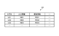
- the log information storage unit 122 stores information related to the log (history). For example, the log information storage unit 122 stores information indicating a history of recognition, prediction, and action planning in automatic driving. The log information storage unit 122 stores information in which the input information to the model in the automatic operation and the basis information regarding the output of the model are associated with each other.
- FIG. 5 is a diagram showing an example of a log information storage unit according to the embodiment of the present disclosure. In the example shown in FIG. 5, the log information storage unit 122 includes items such as "log ID", "input information", and "foundation information".
- Log ID indicates identification information for identifying the log (history).
- Input information indicates the corresponding input information.
- FIG. 5 an example in which conceptual information such as “IND1” is stored in “input information” is shown, but in reality, various data such as input images themselves or a file path name indicating the storage location thereof is shown. Etc. are stored.
- Basis information indicates the corresponding basis information.
- FIG. 5 an example in which conceptual information such as "RINF1" is stored in “ground information” is shown, but in reality, various data such as images generated as ground information or their storage locations are shown. File path name etc. are stored.
- the log (log LG1) identified by the log ID "LG1" indicates that the input information is "IND1" and the basis information is "RINF1".
- the log LG1 indicates that the rationale information indicating the rationale for the output corresponding to the input information IND1 is the rationale information RINF1.
- the log information storage unit 122 is not limited to the above, and may store various information depending on the purpose.
- the log information storage unit 122 stores not only the basis information but also various information in association with the input information.
- the log information storage unit 122 stores the input information in association with the recognition result, the prediction result, the action plan, the traveling information of the moving body, and the like corresponding to the input information.
- the log information storage unit 122 stores the travel information of the actual mobile device 100 based on the route PP11 and the route PP11 in association with the input information IND1.
- control unit 13 for example, a program (for example, an information processing program according to the present disclosure) stored inside the mobile device 100 by a CPU (Central Processing Unit), an MPU (Micro Processing Unit), or the like is stored in a RAM (Random Access Memory). ) Etc. are executed as a work area. Further, the control unit 13 is a controller, and may be realized by an integrated circuit such as an ASIC (Application Specific Integrated Circuit) or an FPGA (Field Programmable Gate Array).
- ASIC Application Specific Integrated Circuit
- FPGA Field Programmable Gate Array
- control unit 13 includes an acquisition unit 131, a recognition unit 132, a prediction unit 133, an action planning unit 134, an execution unit 135, and a generation unit 136, which will be described below. Realize or execute information processing functions and actions.
- the internal configuration of the control unit 13 is not limited to the configuration shown in FIG. 3, and may be another configuration as long as it is a configuration for performing information processing described later.
- the acquisition unit 131 acquires various information.
- the acquisition unit 131 acquires various information from an external information processing device.
- the acquisition unit 131 acquires various information from the storage unit 12.
- the acquisition unit 131 acquires various information from the model information storage unit 121 and the log information storage unit 122.
- the acquisition unit 131 acquires the sensor information detected by the sensor unit 14.
- the acquisition unit 131 stores the acquired information in the storage unit 12.
- the acquisition unit 131 acquires the image information detected by the image sensor 141.
- the acquisition unit 131 acquires the sensor information detected by the distance measuring sensor.
- the acquisition unit 131 acquires a model having a neural network structure and input information input to the model.
- the acquisition unit 131 acquires a model used for controlling a device that acts autonomously.
- the acquisition unit 131 acquires a model used for controlling an autonomously movable moving body.
- the acquisition unit 131 acquires a model used for controlling a moving body which is a vehicle operated by automatic driving.
- the acquisition unit 131 acquires a model that outputs in response to input of sensor information and input information that is sensor information detected by the sensor.
- the acquisition unit 131 acquires a model that outputs the recognition result of the image information in response to the input of the image information and the input information that is the image information.
- the acquisition unit 131 acquires a model including a CNN.
- the acquisition unit 131 acquires a model that outputs in response to the input of output information output by another model and input information that is output information output by the other model.
- the acquisition unit 131 acquires the models M1 to M3 and the like from the model information storage unit 121.
- the acquisition unit 131 acquires the model M1 used for the recognition process.
- the acquisition unit 131 acquires the model M2 used for the prediction process.
- the acquisition unit 131 acquires the model M3 used for processing the action plan.
- the acquisition unit 131 acquires the image IM1 detected by the image sensor 141.
- the acquisition unit 131 acquires the image IM1 as the input information IND1 to the model M1.
- the recognition unit 132 performs recognition processing.
- the recognition unit 132 performs various recognitions.
- the recognition unit 132 recognizes an object.
- the recognition unit 132 recognizes an object by using various information.
- the recognition unit 132 generates various information regarding the recognition result of the object.
- the recognition unit 132 recognizes an object based on the information acquired by the acquisition unit 131.
- the recognition unit 132 recognizes an object by using various sensor information detected by the sensor unit 14.
- the recognition unit 132 recognizes an object by using the image information (sensor information) captured by the image sensor 141.
- the recognition unit 132 recognizes an object included in the image information.
- the recognition unit 132 recognizes various types of information based on the information stored in the model information storage unit 121 and the log information storage unit 122.
- the recognition unit 132 performs recognition processing based on the image IM1 captured by the image sensor 141.
- the recognition unit 132 performs a process of recognizing an object or the like included in the image IM1.
- the recognition unit 132 performs recognition processing using the model M1. For example, the recognition unit 132 inputs the image IM1 as the input information IND1 to the model M1 to cause the model M1 to output the recognition result.
- Prediction unit 133 performs prediction processing.
- the prediction unit 133 predicts various types of information.
- the prediction unit 133 predicts various types of information based on the information acquired from the external information processing device.
- the prediction unit 133 predicts various types of information based on the information stored in the storage unit 12.
- the prediction unit 133 predicts various types of information based on the information stored in the model information storage unit 121 and the log information storage unit 122.
- the prediction unit 133 performs prediction processing based on the output of the model M1.
- the prediction unit 133 performs a process of predicting an action (movement mode) such as movement of an object included in the image IM1.
- the prediction unit 133 performs prediction processing using the model M2.
- the prediction unit 133 causes the model M2 to output the prediction result by inputting the information (recognition result information) output by the model M1 into the model M2.
- the prediction unit 133 predicts the motion mode of the human object OB11.
- the prediction unit 133 predicts the moving direction and speed of the object OB11.
- the prediction unit 133 predicts that the object OB 11 is moving toward the prediction unit 133.
- the prediction unit 133 predicts the motion mode of the object OB12 which is a vehicle.
- the prediction unit 133 predicts the moving direction and speed of the object OB12.
- the prediction unit 133 predicts that the object OB 12 is moving toward the mobile device 100.
- the action planning department 134 makes various plans.
- the action planning unit 134 determines the action plan.
- the action planning unit 134 generates various information regarding the action plan.
- the action planning unit 134 makes various plans based on the information acquired by the acquisition unit 131.
- the action planning unit 134 makes various plans using the information predicted by the prediction unit 133.
- the action planning unit 134 makes an action plan by using various techniques related to the action plan.
- the action planning unit 134 determines the action plan based on the information predicted by the prediction unit 133.
- the action planning unit 134 determines an action plan to move so as to avoid obstacles included in the obstacle map based on the information predicted by the prediction unit 133.
- the action planning unit 134 performs a process of generating an action plan based on the output of the model M2.
- the action planning unit 134 determines the action plan based on the predicted motion mode of the object OB11 and the object OB12.
- the action planning unit 134 performs a process of determining an action plan using the model M3.
- the action planning unit 134 causes the model M3 to output the action plan by inputting the information (prediction result information) output by the model M2 into the model M3.
- the action planning unit 134 plans the action to avoid the objects OB11. To determine.
- the action planning unit 134 plans a path PP11 traveling to the right side in the traveling direction in order to avoid a collision with the object OB11 located on the left side in the traveling direction.
- the action planning unit 134 generates action plan information indicating the route PP11.
- Execution unit 135 executes various information.
- the execution unit 135 executes various processes based on information from an external information processing device.
- the execution unit 135 executes various processes based on the information stored in the storage unit 12.
- the execution unit 135 executes various information based on the information stored in the map information storage unit.
- the execution unit 135 determines various information based on the information acquired by the acquisition unit 131.
- the execution unit 135 executes various processes based on the information predicted by the prediction unit 133.
- the execution unit 135 executes various processes based on the action plan planned by the action planning unit 134.
- the execution unit 135 executes a process related to the action based on the information of the action plan generated by the action planning unit 134.
- the execution unit 135 controls the driving unit 15 to execute an action corresponding to the action plan based on the information of the action plan generated by the action planning unit 134.
- the execution unit 135 executes the movement process of the mobile device 100 according to the action plan under the control of the drive unit 15 based on the information of the action plan.
- the execution unit 135 controls the automatic operation based on the action plan information indicating the route PP11.
- the execution unit 135 controls the movement of the mobile device 100 so as to avoid the human object OB11 based on the action plan information indicating the route PP11.
- Generation unit 136 performs various generations.
- the generation unit 136 generates various information based on the information stored in the storage unit 12.
- the generation unit 136 generates various information based on the information stored in the model information storage unit 121 and the log information storage unit 122.
- the generation unit 136 generates various information based on the sensor information detected by the sensor unit 14.
- the generation unit 136 generates various information based on the image information detected by the image sensor 142.
- the generation unit 136 generates various information based on the information acquired by the acquisition unit 131.
- the generation unit 136 generates various information based on the recognition result by the recognition unit 132.
- the generation unit 136 generates various information based on the prediction result by the prediction unit 133.
- the generation unit 136 generates various information based on the action plan by the action planning unit 134.
- the generation unit 136 generates basis information indicating the basis for the output of the model after the input information is input to the model, based on the state information indicating the state of the model after the input information is input to the model.
- the generation unit 136 generates rationale information indicating the rationale for processing using the output of the model.
- the generation unit 136 generates the basis information indicating the basis of the control of the device after the input information is input to the model.
- the generation unit 136 generates ground information indicating the grounds for controlling the moving body after inputting the input information to the model.
- the generation unit 136 generates basis information indicating the basis of the moving direction of the moving body.
- the generation unit 136 generates the basis information of the model in which the input information is input according to the detection by the sensor.
- the generation unit 136 generates image information indicating the basis for the output of the model as the basis information.
- the generation unit 136 generates a heat map showing the basis for the output of the model as the basis information.
- the generation unit 136 generates the basis information based on the state information including the state of the convolution layer of the model.
- the generation unit 136 generates the basis information by the processing related to CAM (Class Activation Mapping).
- the generation unit 136 generates the basis information by Grad-CAM.
- the generation unit 136 generates the basis information of the model in which the input information is input according to the output by the other model.
- the generation unit 136 generates the basis information based on the state information including the output result of the model after the input information is input to the model.
- the generation unit 136 generates the rationale information based on the rationale model learned by using the input information and the output result.
- the generation unit 136 generates the rationale information by using the rationale model that locally approximates the combination of the input information and the output result.
- the generation unit 136 generates the basis information by the processing related to LIMIT.
- the generation unit 136 stores the log information in which the input information and the basis information are associated with each other in the storage unit.
- the generation unit 136 generates various information to be displayed on the display unit 11.
- the generation unit 136 generates various information such as character information to be displayed on the display unit 11 and image information such as a graph.
- the generation unit 136 may generate information (images) related to the screen such as the basis information RINF1 which is the heat map shown in FIG. 1 by appropriately using various conventional techniques related to the images.
- the generation unit 136 generates an image such as the graph GR11 shown in FIG. 1 by appropriately using various conventional techniques related to GUI.
- the generation unit 136 may generate an image such as a heat map HM11 in CSS, Javascript (registered trademark), HTML, or any language capable of describing information processing such as information display and operation reception described above. ..
- the generation unit 136 shows the basis for showing the basis for the output of the model after the input information is input to the model, based on the state information indicating the state of the model M1 after the input information is input to the model M1. Generate information.
- the generation unit 136 generates basis information indicating the basis for the output of the model M1 after the input of the image IM1 to the model M1 based on the state information indicating the state of the model M1 after the input of the image IM1 to the model M1. ..
- the generation unit 136 generates ground information indicating the grounds regarding the output of the model M1 after the input of the image IM1 by Grad-CAM.
- the generation unit 136 generates the basis information indicating the basis for the output of the model M1 after the input of the image IM1 by the above-mentioned processing related to Grad-CAM.
- the generation unit 136 specifies the target type (class) and generates information (image) corresponding to the specified class. For example, the generation unit 136 generates information (image) for the specified class by various processes such as inverse error propagation using the technology of Grad-CAM.
- the generation unit 136 specifies a class of the type "person” and generates an image having the basis information RINF1 corresponding to the type "person”.
- the generation unit 136 generates the basis information RINF1 which is an image showing the range (area) being watched for the recognition (classification) of the type "person” in the form of a heat map (color map).
- the generation unit 136 generates the basis information RINF1 indicating that the position of the human object OB11 in the image IM1 is the most closely watched and the human object OB11 is recognized.
- the generation unit 136 functions as a rationale information generation unit that generates rationale information for an action based on a plurality of rationale generation algorithms.
- the generation unit 136 generates the basis information of the action based on a plurality of basis generation algorithms such as an algorithm based on the Grad-CAM method, an algorithm based on the LIMIT method, and an algorithm based on the TCAV method.
- the generation unit 136 generates the basis information of the action by using one of the basis generation algorithms among the plurality of basis generation algorithms.
- the generation unit 136 selects one of the rationale generation algorithms among the plurality of rationale generation algorithms, and generates the rationale information of the action using the selected rationale generation algorithm.
- the generation unit 136 selects an algorithm based on the Grad-CAM method from among a plurality of basis generation algorithms, and uses the selected algorithm based on the Grad-CAM method to perform an action. Generate rationale information.
- the sensor unit 14 detects predetermined information.
- the sensor unit 14 has an image sensor 141.
- the image sensor 141 functions as an imaging means for capturing an image.
- the image sensor 141 detects image information.
- the sensor unit 14 is not limited to the image sensor 141, and may have various sensors.
- the sensor unit 14 includes a position sensor, a distance measuring sensor, a sound sensor, an acceleration sensor, a gyro sensor, a temperature sensor, a humidity sensor, an illuminance sensor, a pressure sensor, a proximity sensor, and a living body such as odor, sweat, heartbeat, pulse, and brain wave. It may have various sensors such as a sensor for acquiring information.
- the distance measuring sensor detects the distance between the object to be measured and the distance measuring sensor.
- the distance measuring sensor detects the distance information between the object to be measured and the distance measuring sensor.
- the distance measuring sensor may be an optical sensor.
- the sensor unit 14 has LiDAR (Light Detection and Ringing, Laser Imaging Detection and Ringing) as a range finder.
- the distance measuring sensor is not limited to LiDAR, and may be various sensors such as a ToF (Time of Flight) sensor and a stereo camera. Further, the distance measuring sensor may be a distance measuring sensor using a millimeter wave radar.
- the distance measuring sensor is not limited to LiDAR, and may be various sensors such as a ToF sensor and a stereo camera.
- the position sensor detects the position of the mobile device 100.
- the position sensor may be various sensors such as a GPS (Global Positioning System) sensor. Further, the sensors that detect the above-mentioned various information in the sensor unit 14 may be common sensors, or may be realized by different sensors.
- GPS Global Positioning System
- the drive unit 15 has a function of driving the physical configuration of the mobile device 100.
- the drive unit 15 has a function for moving the position of the mobile device 100.
- the drive unit 15 has a function for moving the position of the mobile device 100, which is an automobile.
- the drive unit 15 is, for example, a motor or the like.
- the drive unit 15 drives the tires and the like of the mobile device 100, which is an automobile.
- the drive unit 15 may have any configuration as long as the mobile device 100 can realize a desired operation.
- the drive unit 15 may have any configuration as long as the position of the mobile device 100 can be moved.
- the drive unit 15 moves the mobile device 100 and changes the position of the mobile device 100 by driving the moving mechanism of the mobile device 100 in response to a driving operation by the user or an instruction by the execution unit 135. To do.
- the mobile device 100 may use various types of models (functions).
- the mobile device 100 may use a regression model such as an SVM (Support Vector Machine) or a model (function) of any form such as a neural network.
- the mobile device 100 may use various regression models such as a non-linear regression model and a linear regression model.
- FIG. 6 is a diagram showing an example of a model according to the embodiment of the present disclosure.
- the network NW1 shown in FIG. 6 shows a neural network including a plurality of (multilayer) intermediate layers between the input layer INL and the output layer OUTL.
- the network NW1 has a structure such as a deep neural network having four or more layers, a so-called deep neural network (deep learning).
- the network NW1 shown in FIG. 6 is a conceptual diagram showing a neural network (model) used for image recognition, corresponding to, for example, the network of the model M1.
- model used for image recognition
- the network NW1 outputs the recognition result from the output layer OUTL.
- the mobile device 100 inputs information to the input layer INL in the network NW1 to output the recognition result corresponding to the input from the output layer OUTL.
- the network NW1 is shown as an example of the model (network), but the network NW1 may be in various formats depending on the application and the like. Further, not only the model M1 but also the models M2, M3 and the like have the same structure such as a deep neural network (deep learning).
- deep learning deep neural network
- FIG. 7 is a flowchart showing an information processing procedure according to the embodiment.
- the mobile device 100 acquires a model having a neural network structure (step S101).
- the mobile device 100 acquires the model M1 from the model information storage unit 121 (see FIG. 3).
- the mobile device 100 acquires the input information input to the model (step S102). For example, the mobile device 100 acquires the image IM1 as the input information IND1 input to the model M1.
- the mobile device 100 generates basis information indicating the basis for the output of the model after the input information is input to the model, based on the state information indicating the state of the model after the input information is input to the model (Ste S103).
- the mobile device 100 is a basis for showing the basis for the output of the model M1 after the input information is input to the model M1 based on the state information indicating the state of the model M1 after the input information IND1 is input to the model M1.
- Information RINF1 is generated.
- the mobile device 100 displays the generated basis information RINF1.
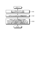
- FIG. 8 is a flowchart showing the procedure of the control process of the moving body.
- the mobile device 100 acquires an image from the sensor (step S201).
- the mobile device 100 acquires an image from the image sensor 141.
- the mobile device 100 stores the acquired image as log data (step S202).
- the mobile device 100 stores the image as log data in the log information storage unit 122.
- the mobile device 100 displays a heat map on the pedestrian (step S204). For example, when a pedestrian is detected, the mobile device 100 generates and displays ground information which is a heat map of an aspect in which the position of the pedestrian is noticed.
- the mobile device 100 stores the generated basis information as log data (step S202).
- the mobile device 100 stores the generated basis information in the log information storage unit 122 in association with the image as the generation base.
- the mobile device 100 executes a steering wheel operation to avoid pedestrians (step S205).
- the mobile device 100 receives a steering wheel operation by the user and executes the movement control according to the received steering wheel operation.
- the mobile device 100 stores the received handle operation information as log data (step S202).
- the mobile device 100 stores the received handle operation information in the log information storage unit 122 in association with the corresponding image and ground information.
- step S203 if the mobile device 100 does not detect a pedestrian (step S203: No), the mobile device 100 ends without performing the processes of steps S204 and S205.
- FIG. 9 is a diagram showing another example of information processing according to the embodiment. The same points as in FIG. 1 will be omitted as appropriate.
- a user (user U) is on board the mobile device 100, and the mobile device 100 is traveling on the road RD21.
- the direction from the mobile device 100 toward the objects OB21 and OB22, which will be described later, is in front of the mobile device 100, and the mobile device 100 is traveling forward. Is shown. It is assumed that the side portion of the road RD 21 is an area such as a wall surface where the mobile device 100 cannot enter.
- the mobile device 100 detects by the sensor unit 14 (see FIG. 3) (step S21). In the example of FIG. 9, the mobile device 100 detects (images) the image IM 21 by the image sensor 141.
- the mobile device 100 performs the recognition process (step S22).
- the mobile device 100 performs recognition processing based on the image IM21 captured by the image sensor 141.
- the mobile device 100 performs a process of recognizing an object or the like included in the image IM21.
- the mobile device 100 performs the recognition process using the model M1 in the same manner as in FIG.
- the moving body device 100 indicates that the object OB21 of the type “human” exists in the model M1 at the position (region) on the left side of the image IM21 by inputting the image IM21 into the model M1. Output information. Further, by inputting the image IM21 into the model M1, the moving body device 100 causes the model M1 to output information indicating that the object OB22 of the type "vehicle” exists at the position (area) on the right side of the image IM21. .. Then, the mobile device 100 performs the processes of steps S23 to S26. In the example of FIG. 9, steps S23 to S26 are added to each process for convenience of explanation, but it does not indicate that step S25 is performed after step S24. For example, the processes of steps S23 to S24 and the processes of steps S25 to S26 are performed in parallel.
- the mobile device 100 performs a generation process (step S23).
- the mobile device 100 generates basis information indicating the basis for the output of the model after the input information is input to the model, based on the state information indicating the state of the model M1 after the input information is input to the model M1.
- the mobile device 100 generates evidence information indicating the basis for the output of the model M1 after the input of the image IM21 to the model M1 based on the state information indicating the state of the model M1 after the input of the image IM21 to the model M1. To do.
- the mobile device 100 uses Grad-CAM to generate evidence information indicating the basis for the output of the model M1 after the input of the image IM21.
- the mobile device 100 specifies a class of the type "person” and generates an image having the basis information RINF21 corresponding to the type "person".
- the ground information RINF21 is an image showing a range (area) being watched for recognition (classification) of the type "person” in the form of a so-called heat map (color map). is there.
- FIG. 1 the ground information RINF21 is an image showing a range (area) being watched for recognition (classification) of the type "person” in the form of a so-called heat map (color map). is there.
- the basis information RINF21 indicates that the position of the human object OB21 in the image IM21 is not being watched, and the human object OB21 is not properly recognized. Further, in the example of FIG. 9, it is assumed that the mobile device 100 appropriately recognizes the object OB12 which is a vehicle.
- the mobile device 100 performs display processing (step S24).
- the mobile device 100 displays the generated basis information RINF 21 on the display unit 11 (see FIG. 3).
- the user U since the human object OB21 is not properly recognized as shown in the basis information RINF21, the user U switches the automatic operation state of the mobile device 100 to manual operation and operates by himself / herself. You may switch to driving.
- the mobile device 100 stores the basis information RINF21 as a history in the storage unit 12 (see FIG. 3) in association with the image IM21 which is the input information (input information IND21) as the basis thereof.
- the mobile device 100 stores the input information IND21 and the basis information RINF21 in association with each other in the log information storage unit 122 (see FIG. 3). This makes it possible to verify what kind of input the mobile device 100 has determined to perform the subsequent operation.
- step S25 is performed as soon as the process of step S22 is completed.
- the mobile device 100 performs a prediction process based on the recognition result of the recognition process (step S25).
- the mobile device 100 performs prediction processing based on the output of the model M1.
- the mobile device 100 performs a process of predicting an action (movement mode) such as movement of an object included in the image IM21. Similar to FIG. 1, the mobile device 100 performs prediction processing using the model M2.
- the mobile device 100 predicts the motion mode of the recognized vehicle object OB22.
- the mobile device 100 predicts the moving direction and speed of the object OB22. In the example of FIG. 9, the mobile device 100 predicts that the object OB 22 is moving toward the mobile device 100.
- the mobile device 100 performs a process of determining an action plan based on the prediction result of the prediction process (step S26).
- the mobile device 100 performs a process of generating an action plan based on the output of the model M2.
- the mobile device 100 determines an action plan based on the predicted motion mode of the object OB22. Similar to FIG. 1, the mobile device 100 performs a process of determining an action plan using the model M3. In the example of FIG. 9, since the object OB22 is located in the traveling direction of the moving body device 100 and is approaching the moving body device 100, the action plan is determined so as to avoid the object OB22.
- the moving body device 100 plans a path PP21 traveling to the left side in the traveling direction in order to avoid a collision with the object OB22 located on the right side in the traveling direction.
- the mobile device 100 generates action plan information indicating the route PP21.
- the mobile device 100 controls the automatic operation based on the action plan information indicating the route PP21.
- the mobile device 100 stores the input information IND21 in association with the travel information of the actual mobile device 100 based on the route PP21 and the route PP21 in the log information storage unit 122 (see FIG. 3). This makes it possible for the mobile device 100 to verify what kind of input the mobile device 100 has made and what kind of plan the mobile device 100 has traveled.
- the moving body device 100 could not detect (recognize) the pedestrian object OB21 by the image IM21 detected by the image sensor 141, so that the object OB21 is not highlighted.
- the ground information RINF21 which is a map is displayed on the display unit 11.
- the pedestrian since the pedestrian could not be detected from the sensor in the automatic driving, the pedestrian is not highlighted by the heat map by the visualization display device (for example, the display unit 11 or the like).
- the moving body device 100 since the moving body device 100 cannot properly recognize the pedestrian object OB21, in order to avoid the vehicle object OB22, the moving body device 100 takes a path toward the pedestrian object OB21 and is an object. Approach OB21.
- the mobile device 100 displays the ground information RINF21, which is a heat map in which the pedestrian object OB21 is not highlighted, in real time.
- the occupant of the mobile device 100 can recognize that the mobile device 100 is not recognizing a person and therefore is taking a course toward the person.
- the passenger of the mobile device 100 tries to take a course in the direction in which the person is in order to avoid the oncoming vehicle because the mobile device 100 traveling by automatic driving cannot properly recognize the person. You can see that there is. Therefore, the occupant of the mobile device 100 can avoid an accident in contact with a person by switching to the emergency manual operation, stopping the automatic operation, and operating the handle portion and the brake portion by himself / herself. it can.
- the moving body device 100 comes into contact with the pedestrian object OB21 because the automatic driving determines that the moving body device 100 moves to the left in order to avoid the oncoming vehicle which is the object OB22.
- the moving body device 100 is a pedestrian object because the ground information RINF21, which is a heat map in which the pedestrian object OB21 is not highlighted, is stored in the storage unit 12. It is possible to provide information indicating the reason (rationale) that the contact with the OB 21 is due to the fact that the object OB 21 was not properly recognized. That is, the mobile device 100 can prove from the log data that it was caused by the automatic driving system (sensor system) not being able to recognize the pedestrian as an explanation of the contact accident with a person.
- FIG. 10 is a diagram showing an example of a conceptual diagram of the configuration of the in-vehicle system.
- the in-vehicle system FCB1 shown in FIG. 10 is a system mounted on a vehicle (moving body) for automatic driving.
- the mobile device 100 is an automobile equipped with the in-vehicle system FCB1 as shown in FIG.
- the in-vehicle system FCB1 shown in FIG. 10 includes a sensor unit, artificial intelligence, an automatic driving control unit, and the like. In addition, the in-vehicle system FCB1 performs processes such as visualization display, log storage, and emergency manual driving.
- the sensor unit of the in-vehicle system FCB1 detects, for example, information outside the vehicle.
- the sensor unit of the in-vehicle system FCB1 corresponds to the sensor unit 14 and the like of the mobile device 100.
- the sensor unit of the in-vehicle system FCB1 captures an image.
- the artificial intelligence of the in-vehicle system FCB1 includes a cognitive system and a judgment system.
- the cognitive system of the in-vehicle system FCB1 performs processing of external world recognition and prediction.
- the recognition system of the in-vehicle system FCB1 corresponds to the recognition unit 132, the prediction unit 133, and the like of the mobile device 100.
- the recognition system of the in-vehicle system FCB1 recognizes the outside world based on the information (sensor information) detected by the sensor unit of the in-vehicle system FCB1. Further, the cognitive system of the in-vehicle system FCB1 makes a prediction based on the result of the recognition of the outside world.
- the judgment system of the in-vehicle system FCB1 processes the action plan.
- the determination system of the in-vehicle system FCB1 corresponds to the action planning unit 134 and the like of the mobile device 100.
- the judgment system of the in-vehicle system FCB1 makes an action plan based on the prediction result of the cognitive system of the in-vehicle system FCB1.
- the automatic driving control unit of the in-vehicle system FCB1 controls automatic driving.
- the automatic driving control unit of the in-vehicle system FCB1 corresponds to the execution unit 135 of the mobile device 100, each configuration for controlling driving, and the like.
- the automatic driving control unit of the in-vehicle system FCB1 controls the driving based on the action plan generated by the judgment system of the in-vehicle system FCB1.
- the visualization display of the in-vehicle system FCB1 is a process of displaying various types of information.
- the visualization display of the in-vehicle system FCB1 is realized by the functions of the display unit 11 and the generation unit 136 of the mobile device 100.
- the visualization display of the in-vehicle system FCB1 displays information on the sensor unit and artificial intelligence.
- the visualization display of the in-vehicle system FCB1 displays the basis information indicating the basis for the judgment of artificial intelligence. For example, the visualization display of the in-vehicle system FCB1 generates and displays the basis information based on the information of artificial intelligence.
- Log saving of the in-vehicle system FCB1 is a process of saving various information as a log.
- the log storage of the in-vehicle system FCB1 is realized by the function of the storage unit 12 or the like of the mobile device 100.
- the log storage of the in-vehicle system FCB1 saves the information of the visualization display and the judgment system of the in-vehicle system FCB1 as a log.
- the log storage of the in-vehicle system FCB1 stores the sensor information as a log in association with the information of the outside world recognition, prediction, and action plan based on the sensor information.
- the emergency manual driving of the in-vehicle system FCB1 is a process of performing control according to the manual driving by a user (passenger) who gets on the vehicle equipped with the in-vehicle system FCB1.
- the emergency manual operation of the in-vehicle system FCB1 is realized by a configuration that accepts various driving operations by the user such as the bundle unit, the accelerator unit, and the brake unit of the mobile device 100.
- the control is stopped by the automatic driving control unit, and the running of the vehicle equipped with the in-vehicle system FCB1 is controlled according to the manual driving by the user. Is done.
- the in-vehicle system FCB1 as described above visualizes the grounds on which deep learning, which is called a black box, makes a judgment in automatic driving by AI.
- the artificial intelligence unit in the in-vehicle system FCB1 is composed of a cognitive system and a judgment system.
- the cognitive system recognizes and predicts the outside world and provides the information that is the basis for the judgment system.
- the image that is the basis for the judgment can be visualized by highlighting it with a heat map.
- the driver of the vehicle detects a dangerous situation by looking at the visualization display, he / she can avoid an accident by switching from automatic driving to emergency manual driving.
- the driver can know the judgment basis of artificial intelligence, which was conventionally called a black box, in real time, and can support driving for safe driving. For example, when autonomous driving suddenly tries to turn to the left, it is possible to know whether it is to avoid people or obstacles by the visualization technology of the judgment basis of deep learning. For example, a sudden change of direction to the left may lead to the presence of an object such as a person. If the driver is driving in the direction of an obstacle without turning the steering wheel to the left by automatic driving, it is possible to avoid a property damage accident and a personal injury accident. In addition, in the unlikely event that an accident occurs, the basis for judgment in automatic driving is recorded, so it is possible to prove the negligence in automatic driving.
- the processing according to each of the above-described embodiments may be carried out in various different forms (modifications) other than each of the above-described embodiments.
- the information processing device that performs information processing is the mobile device 100, but the information processing device may be a server device.
- the information processing device may be a server device that generates ground information using information received from another device. That is, the information processing apparatus may have only the configuration necessary for performing the process of generating the basis information.
- An information processing system including an information processing device that generates ground information may be configured.
- the information processing system may be configured to include an information processing device that generates ground information and a display device that displays the ground information generated by the information processing device. That is, the information processing system may be configured to include a device for generating ground information and a device for displaying ground information.
- FIG. 11 is a diagram showing a configuration example of an information processing system according to a modified example of the present disclosure.
- FIG. 12 is a diagram showing a configuration example of an information processing device according to a modified example of the present disclosure.
- the information processing system 1 includes a mobile device 10 and an information processing device 100A.
- the mobile device 10 and the information processing device 100A are connected to each other via a network N so as to be communicable by wire or wirelessly.
- the information processing system 1 shown in FIG. 11 may include a plurality of mobile devices 10 and a plurality of information processing devices 100A.
- the information processing device 100A communicates with the mobile device 10 via the network N, and gives an instruction to control the mobile device 10 based on the information collected by the mobile device 10 and various sensors. May be good.
- the information processing device 100A may be arranged at any place.
- the information processing device 100A may be arranged outside the mobile device 10 or may be mounted on the mobile device 10.
- the mobile device 10 is an automobile that travels by automatic driving.
- the mobile device 10 transmits sensor information detected by a sensor such as an image sensor to the information processing device 100A.
- the mobile device 10 transmits the image captured by the image sensor to the information processing device 100A.
- the information processing device 100A acquires the image captured by the image sensor.
- the mobile device 10 may be any device as long as it can transmit and receive information to and from the information processing device 100A, and may be, for example, various mobile bodies such as an autonomous mobile robot and a drone. You may.
- the information processing device 100A is an information processing device that performs various types of information processing using information received from the mobile device 10.
- the information processing device 100A provides the mobile device 10 with information for controlling the mobile device 10, such as information on an action plan.
- the mobile device 10 that has received the action plan information from the information processing device 100A controls and moves based on the action plan information.
- the information processing device 100A provides the generated basis information to the mobile device 10.
- the mobile device 10 that has received the ground information from the information processing device 100A displays the ground information.
- the information processing device 100A includes a storage unit 12, a control unit 13A, and a communication unit 16.
- the communication unit 16 is connected to the network N (Internet or the like) by wire or wirelessly, and transmits / receives information to / from the mobile device 10 via the network N.
- the storage unit 12 stores information for controlling the movement of the mobile device 10, various information received from the mobile device 10, and various information to be transmitted to the mobile device 10.
- the information processing device 100A has a configuration for transmitting and receiving information to and from an external device such as the mobile device 10.
- the information processing device 100A does not have a sensor unit, a drive unit, or the like, and does not have to have a configuration for realizing a function as a mobile device.
- the information processing device 100A includes an input unit (for example, a keyboard, a mouse, etc.) that receives various operations from an administrator or the like that manages the information processing device 100A, and a display unit (for example, a liquid crystal display, etc.) for displaying various information. ) May have.
- the control unit 13A has an acquisition unit 131, a recognition unit 132, a prediction unit 133, an action planning unit 134, an execution unit 135, a generation unit 136, and a transmission unit 137.
- the transmission unit 137 transmits various information.
- the transmission unit 137 provides various types of information.
- the transmission unit 137 provides various information to an external information processing device.
- the transmission unit 137 transmits various information to an external information processing device.
- the transmission unit 137 transmits the information stored in the storage unit 12.
- the transmission unit 137 transmits the information generated by the generation unit 136.
- the transmission unit 137 transmits information to the mobile device 10.
- the transmission unit 137 transmits the information of the action plan generated by the action planning unit 134 to the mobile device 10.
- the transmission unit 137 controls the operation of the mobile device 10 by transmitting the information of the action plan generated by the action planning unit 134 to the mobile device 10.
- the transmission unit 137 controls the automatic operation of the mobile device 10 by transmitting the information of the action plan to the mobile device 10.
- the mobile device 100 and the information processing system 1 described above may have a configuration as shown in FIG.
- the mobile device 100 may have the following configurations in addition to the configurations shown in FIG.
- each part shown below may be included in the structure shown in FIG. 3, for example.
- FIG. 13 is a block diagram showing a configuration example of a schematic function of a mobile control system to which the present technology can be applied.
- the automatic driving control unit 212 and the motion control unit 235 of the vehicle control system 200 correspond to the execution unit 135 of the mobile device 100.
- the detection unit 231 of the automatic operation control unit 212, the self-position estimation unit 232, and the situation analysis unit 233 correspond to the recognition unit 132 and the prediction unit 133 of the mobile device 100.
- the planning unit 234 of the automatic operation control unit 212 corresponds to the action planning unit 134 of the mobile device 100.
- the automatic operation control unit 212 may have blocks corresponding to each processing unit of the control unit 13 in addition to the blocks shown in FIG.
- a vehicle provided with the vehicle control system 200 is distinguished from other vehicles, it is referred to as a own vehicle or a own vehicle.
- the vehicle control system 200 includes an input unit 201, a data acquisition unit 202, a communication unit 203, an in-vehicle device 204, an output control unit 205, an output unit 206, a drive system control unit 207, a drive system system 208, a body system control unit 209, and a body. It includes a system system 210, a storage unit 211, and an automatic operation control unit 212.
- the input unit 201, the data acquisition unit 202, the communication unit 203, the output control unit 205, the drive system control unit 207, the body system control unit 209, the storage unit 211, and the automatic operation control unit 212 are via the communication network 221. They are interconnected.
- the communication network 221 is, for example, from an in-vehicle communication network or bus that conforms to any standard such as CAN (Controller Area Network), LIN (Local Interconnect Network), LAN (Local Area Network), or FlexRay (registered trademark). Become. Each part of the vehicle control system 200 may be directly connected without going through the communication network 221.
- CAN Controller Area Network
- LIN Local Interconnect Network
- LAN Local Area Network
- FlexRay registered trademark
- the description of the communication network 221 shall be omitted.
- the input unit 201 and the automatic operation control unit 212 communicate with each other via the communication network 221, it is described that the input unit 201 and the automatic operation control unit 212 simply communicate with each other.
- the input unit 201 includes a device used by the passenger to input various data, instructions, and the like.
- the input unit 201 includes an operation device such as a touch panel, a button, a microphone, a switch, and a lever, and an operation device capable of inputting by a method other than manual operation by voice or gesture.
- the input unit 201 may be a remote control device using infrared rays or other radio waves, or an externally connected device such as a mobile device or a wearable device corresponding to the operation of the vehicle control system 200.
- the input unit 201 generates an input signal based on data, instructions, and the like input by the passenger, and supplies the input signal to each unit of the vehicle control system 200.
- the data acquisition unit 202 includes various sensors and the like that acquire data used for processing of the vehicle control system 200, and supplies the acquired data to each unit of the vehicle control system 200.
- the data acquisition unit 202 includes various sensors for detecting the state of the own vehicle and the like.
- the data acquisition unit 202 includes a gyro sensor, an acceleration sensor, an inertial measurement unit (IMU), an accelerator pedal operation amount, a brake pedal operation amount, a steering wheel steering angle, and an engine speed. It is equipped with a sensor or the like for detecting the rotation speed of the motor, the rotation speed of the wheels, or the like.
- IMU inertial measurement unit
- the data acquisition unit 202 includes various sensors for detecting information outside the own vehicle.
- the data acquisition unit 202 includes an imaging device such as a ToF (Time Of Flight) camera, a stereo camera, a monocular camera, an infrared camera, and other cameras.
- the data acquisition unit 202 includes an environment sensor for detecting the weather or the weather, and a surrounding information detection sensor for detecting an object around the own vehicle.
- the environmental sensor includes, for example, a raindrop sensor, a fog sensor, a sunshine sensor, a snow sensor, and the like.
- the ambient information detection sensor includes, for example, an ultrasonic sensor, a radar, a LiDAR (Light Detection and Ringing, a Laser Imaging Detection and Ringing), a sonar, and the like.
- the data acquisition unit 202 is provided with various sensors for detecting the current position of the own vehicle.
- the data acquisition unit 202 includes a GNSS receiver or the like that receives a GNSS signal from a GNSS (Global Navigation Satellite System) satellite.
- GNSS Global Navigation Satellite System
- the data acquisition unit 202 includes various sensors for detecting information in the vehicle.
- the data acquisition unit 202 includes an imaging device that images the driver, a biosensor that detects the driver's biological information, a microphone that collects sound in the vehicle interior, and the like.
- the biosensor is provided on, for example, the seat surface or the steering wheel, and detects the biometric information of the passenger sitting on the seat or the driver holding the steering wheel.
- the communication unit 203 communicates with the in-vehicle device 204 and various devices, servers, base stations, etc. outside the vehicle, transmits data supplied from each unit of the vehicle control system 200, and transmits the received data to the vehicle control system. It is supplied to each part of 200.
- the communication protocol supported by the communication unit 203 is not particularly limited, and the communication unit 203 may support a plurality of types of communication protocols.
- the communication unit 203 wirelessly communicates with the in-vehicle device 204 by wireless LAN, Bluetooth (registered trademark), NFC (Near Field Communication), WUSB (Wireless USB), or the like. Further, for example, the communication unit 203 uses USB (Universal Serial Bus), HDMI (registered trademark) (High-Definition Multimedia Interface) (registered trademark), via a connection terminal (and a cable if necessary) (not shown). Alternatively, wire communication is performed with the in-vehicle device 204 by MHL (Mobile High-definition Link) or the like.
- MHL Mobile High-definition Link
- the communication unit 203 with a device (for example, an application server or a control server) existing on an external network (for example, the Internet, a cloud network or a network peculiar to a business operator) via a base station or an access point.
- a device for example, an application server or a control server
- an external network for example, the Internet, a cloud network or a network peculiar to a business operator
- the communication unit 203 uses P2P (Peer To Peer) technology to connect with a terminal (for example, a pedestrian or store terminal, or an MTC (Machine Type Communication) terminal) existing in the vicinity of the own vehicle. Communicate.
- P2P Peer To Peer
- a terminal for example, a pedestrian or store terminal, or an MTC (Machine Type Communication) terminal
- the communication unit 203 can be used for vehicle-to-vehicle (Vehicle to Vehicle) communication, road-to-vehicle (Vehicle to Infrastructure) communication, vehicle-to-house (Vehicle to Home) communication, and pedestrian-to-vehicle (Vehicle to Pedestrian) communication. ) Perform V2X communication such as communication.
- the communication unit 203 is provided with a beacon receiving unit, receives radio waves or electromagnetic waves transmitted from a radio station or the like installed on the road, and acquires information such as the current position, traffic congestion, traffic regulation, or required time. To do.
- the in-vehicle device 204 includes, for example, a mobile device or a wearable device owned by a passenger, an information device carried in or attached to the own vehicle, a navigation device for searching a route to an arbitrary destination, and the like.
- the output control unit 205 controls the output of various information to the passengers of the own vehicle or the outside of the vehicle.
- the output control unit 205 generates an output signal including at least one of visual information (for example, image data) and auditory information (for example, audio data) and supplies the output signal to the output unit 206.
- the output control unit 205 synthesizes image data captured by different imaging devices of the data acquisition unit 202 to generate a bird's-eye view image, a panoramic image, or the like, and outputs an output signal including the generated image. It is supplied to the output unit 206.
- the output control unit 205 generates voice data including a warning sound or a warning message for dangers such as collision, contact, and entry into a danger zone, and outputs an output signal including the generated voice data to the output unit 206.
- Supply for example, the output control unit 205 generates voice data including a warning sound or a warning message for dangers such as collision, contact, and entry into
- the output unit 206 is provided with a device capable of outputting visual information or auditory information to the passengers of the own vehicle or the outside of the vehicle.
- the output unit 206 includes a display device, an instrument panel, an audio speaker, headphones, a wearable device such as a spectacle-type display worn by a passenger, a projector, a lamp, and the like.
- the display device included in the output unit 206 displays visual information in the driver's field of view, such as a head-up display, a transmissive display, and a device having an AR (Augmented Reality) display function, in addition to the device having a normal display. It may be a display device.
- the drive system control unit 207 controls the drive system system 208 by generating various control signals and supplying them to the drive system system 208. Further, the drive system control unit 207 supplies control signals to each unit other than the drive system system 208 as necessary, and notifies the control state of the drive system system 208.
- the drive system system 208 includes various devices related to the drive system of the own vehicle.
- the drive system system 208 includes a drive force generator for generating a drive force of an internal combustion engine or a drive motor, a drive force transmission mechanism for transmitting the drive force to the wheels, a steering mechanism for adjusting the steering angle, and the like. It is equipped with a braking device that generates braking force, ABS (Antilock Brake System), ESC (Electronic Stability Control), an electric power steering device, and the like.
- the body system control unit 209 controls the body system 210 by generating various control signals and supplying them to the body system 210. Further, the body system control unit 209 supplies a control signal to each unit other than the body system 210 as necessary, and notifies the control state of the body system 210 and the like.
- the body system 210 includes various body devices equipped on the vehicle body.
- the body system 210 includes a keyless entry system, a smart key system, a power window device, a power seat, a steering wheel, an air conditioner, and various lamps (for example, head lamps, back lamps, brake lamps, winkers, fog lamps, etc.). Etc. are provided.
- the storage unit 211 includes, for example, a magnetic storage device such as a ROM (Read Only Memory), a RAM (Random Access Memory), an HDD (Hard Disc Drive), a semiconductor storage device, an optical storage device, an optical magnetic storage device, and the like. ..
- the storage unit 211 stores various programs, data, and the like used by each unit of the vehicle control system 200.
- the storage unit 211 has map data such as a three-dimensional high-precision map such as a dynamic map, a global map which is less accurate than the high-precision map and covers a wide area, and a local map including information around the own vehicle.
- map data such as a three-dimensional high-precision map such as a dynamic map, a global map which is less accurate than the high-precision map and covers a wide area, and a local map including information around the own vehicle.
- the automatic driving control unit 212 controls automatic driving such as autonomous driving or driving support. Specifically, for example, the automatic driving control unit 212 issues collision avoidance or impact mitigation of the own vehicle, follow-up running based on the inter-vehicle distance, vehicle speed maintenance running, collision warning of the own vehicle, lane deviation warning of the own vehicle, and the like. Collision control is performed for the purpose of realizing the functions of ADAS (Advanced Driver Assistance System) including. Further, for example, the automatic driving control unit 212 performs cooperative control for the purpose of automatic driving that autonomously travels without depending on the operation of the driver.
- the automatic operation control unit 212 includes a detection unit 231, a self-position estimation unit 232, a situation analysis unit 233, a planning unit 234, and an operation control unit 235.
- the detection unit 231 detects various types of information necessary for controlling automatic operation.
- the detection unit 231 includes an outside information detection unit 241, an inside information detection unit 242, and a vehicle state detection unit 243.
- the vehicle outside information detection unit 241 performs detection processing of information outside the own vehicle based on data or signals from each unit of the vehicle control system 200. For example, the vehicle outside information detection unit 241 performs detection processing, recognition processing, tracking processing, and distance detection processing for an object around the own vehicle. Objects to be detected include, for example, vehicles, people, obstacles, structures, roads, traffic lights, traffic signs, road markings, and the like. Further, for example, the vehicle outside information detection unit 241 performs detection processing of the environment around the own vehicle. The surrounding environment to be detected includes, for example, weather, temperature, humidity, brightness, road surface condition, and the like.
- the vehicle outside information detection unit 241 outputs data indicating the result of the detection process to the self-position estimation unit 232, the map analysis unit 251 of the situation analysis unit 233, the traffic rule recognition unit 252, the situation recognition unit 253, and the operation control unit 235. It is supplied to the emergency situation avoidance unit 271 and the like.
- the in-vehicle information detection unit 242 performs in-vehicle information detection processing based on data or signals from each unit of the vehicle control system 200.
- the vehicle interior information detection unit 242 performs driver authentication processing and recognition processing, driver status detection processing, passenger detection processing, vehicle interior environment detection processing, and the like.
- the state of the driver to be detected includes, for example, physical condition, arousal level, concentration level, fatigue level, line-of-sight direction, and the like.
- the environment inside the vehicle to be detected includes, for example, temperature, humidity, brightness, odor, and the like.
- the in-vehicle information detection unit 242 supplies data indicating the result of the detection process to the situation recognition unit 253 of the situation analysis unit 233, the emergency situation avoidance unit 271 of the operation control unit 235, and the like.
- the vehicle state detection unit 243 performs the state detection process of the own vehicle based on the data or signals from each part of the vehicle control system 200.
- the states of the own vehicle to be detected include, for example, speed, acceleration, steering angle, presence / absence and content of abnormality, driving operation state, power seat position / tilt, door lock state, and other in-vehicle devices. The state etc. are included.
- the vehicle state detection unit 243 supplies data indicating the result of the detection process to the situation recognition unit 253 of the situation analysis unit 233, the emergency situation avoidance unit 271 of the operation control unit 235, and the like.
- the self-position estimation unit 232 estimates the position and attitude of the own vehicle based on data or signals from each unit of the vehicle control system 200 such as the vehicle exterior information detection unit 241 and the situation recognition unit 253 of the situation analysis unit 233. Perform processing. In addition, the self-position estimation unit 232 generates a local map (hereinafter, referred to as a self-position estimation map) used for self-position estimation, if necessary.
- the map for self-position estimation is, for example, a highly accurate map using a technique such as SLAM (Simultaneous Localization and Mapping).
- the self-position estimation unit 232 supplies data indicating the result of the estimation process to the map analysis unit 251 of the situation analysis unit 233, the traffic rule recognition unit 252, the situation recognition unit 253, and the like. Further, the self-position estimation unit 232 stores the self-position estimation map in the storage unit 211.
- the situation analysis unit 233 analyzes the situation of the own vehicle and the surroundings.
- the situation analysis unit 233 includes a map analysis unit 251, a traffic rule recognition unit 252, a situation recognition unit 253, and a situation prediction unit 254.
- the map analysis unit 251 uses data or signals from each unit of the vehicle control system 200 such as the self-position estimation unit 232 and the vehicle exterior information detection unit 241 as necessary, and uses data or signals of various maps stored in the storage unit 211. Perform analysis processing and build a map containing information necessary for automatic driving processing.
- the map analysis unit 251 applies the constructed map to the traffic rule recognition unit 252, the situation recognition unit 253, the situation prediction unit 254, the route planning unit 261 of the planning unit 234, the action planning unit 262, the operation planning unit 263, and the like. Supply to.
- the traffic rule recognition unit 252 determines the traffic rules around the vehicle based on data or signals from each unit of the vehicle control system 200 such as the self-position estimation unit 232, the vehicle outside information detection unit 241 and the map analysis unit 251. Perform recognition processing. By this recognition process, for example, the position and state of the signal around the own vehicle, the content of the traffic regulation around the own vehicle, the lane in which the vehicle can travel, and the like are recognized.
- the traffic rule recognition unit 252 supplies data indicating the result of the recognition process to the situation prediction unit 254 and the like.
- the situation recognition unit 253 can be used for data or signals from each unit of the vehicle control system 200 such as the self-position estimation unit 232, the vehicle exterior information detection unit 241, the vehicle interior information detection unit 242, the vehicle condition detection unit 243, and the map analysis unit 251. Based on this, the situation recognition process related to the own vehicle is performed. For example, the situational awareness unit 253 recognizes the situation of the own vehicle, the situation around the own vehicle, the situation of the driver of the own vehicle, and the like. In addition, the situation recognition unit 253 generates a local map (hereinafter, referred to as a situation recognition map) used for recognizing the situation around the own vehicle, if necessary.
- the situational awareness map is, for example, an Occupancy Grid Map.
- the status of the own vehicle to be recognized includes, for example, the position, posture, movement (for example, speed, acceleration, moving direction, etc.) of the own vehicle, and the presence / absence and contents of an abnormality.
- the surrounding conditions of the vehicle to be recognized include, for example, the type and position of surrounding stationary objects, the type, position and movement of surrounding animals (for example, speed, acceleration, moving direction, etc.), and the surrounding roads.
- the composition and road surface condition, as well as the surrounding weather, temperature, humidity, brightness, etc. are included.
- the state of the driver to be recognized includes, for example, physical condition, alertness, concentration, fatigue, eye movement, and driving operation.
- the situational awareness unit 253 supplies data indicating the result of the recognition process (including a situational awareness map, if necessary) to the self-position estimation unit 232, the situation prediction unit 254, and the like. Further, the situational awareness unit 253 stores the situational awareness map in the storage unit 211.
- the situational awareness unit 254 performs situational awareness processing related to the own vehicle based on data or signals from each unit of the vehicle control system 200 such as the map analysis unit 251 and the traffic rule recognition unit 252 and the situational awareness unit 253.
- the situation prediction unit 254 performs prediction processing such as the situation of the own vehicle, the situation around the own vehicle, and the situation of the driver.
- the situation of the own vehicle to be predicted includes, for example, the behavior of the own vehicle, the occurrence of an abnormality, the mileage, and the like.
- the situation around the own vehicle to be predicted includes, for example, the behavior of the animal body around the own vehicle, the change in the signal state, the change in the environment such as the weather, and the like.
- the driver's situation to be predicted includes, for example, the driver's behavior and physical condition.
- the situation prediction unit 254 together with the data from the traffic rule recognition unit 252 and the situation recognition unit 253, displays the data showing the result of the prediction processing, the route planning unit 261 of the planning unit 234, the action planning unit 262, and the operation planning unit 263. And so on.
- the route planning unit 261 plans a route to the destination based on data or signals from each unit of the vehicle control system 200 such as the map analysis unit 251 and the situation prediction unit 254. For example, the route planning unit 261 sets a route from the current position to the specified destination based on the global map. Further, for example, the route planning unit 261 changes the route as appropriate based on the conditions such as traffic congestion, accidents, traffic restrictions, construction work, and the physical condition of the driver. The route planning unit 261 supplies data indicating the planned route to the action planning unit 262 and the like.
- the action planning unit 262 safely completes the route planned by the route planning unit 261 within the planned time based on the data or signals from each unit of the vehicle control system 200 such as the map analysis unit 251 and the situation prediction unit 254. Plan your vehicle's actions to drive. For example, the action planning unit 262 plans starting, stopping, traveling direction (for example, forward, backward, left turn, right turn, change of direction, etc.), traveling lane, traveling speed, and overtaking. The action planning unit 262 supplies data indicating the planned behavior of the own vehicle to the action planning unit 263 and the like.
- the motion planning unit 263 is the operation of the own vehicle for realizing the action planned by the action planning unit 262 based on the data or signals from each unit of the vehicle control system 200 such as the map analysis unit 251 and the situation prediction unit 254. Plan. For example, the motion planning unit 263 plans acceleration, deceleration, traveling track, and the like. The motion planning unit 263 supplies data indicating the planned operation of the own vehicle to the acceleration / deceleration control unit 272 and the direction control unit 273 of the motion control unit 235.
- the motion control unit 235 controls the motion of the own vehicle.
- the operation control unit 235 includes an emergency situation avoidance unit 271, an acceleration / deceleration control unit 272, and a direction control unit 273.
- the emergency situation avoidance unit 271 is based on the detection results of the vehicle exterior information detection unit 241 and the vehicle interior information detection unit 242, and the vehicle condition detection unit 243, and is based on the detection results of collision, contact, entry into a danger zone, driver abnormality, vehicle Performs emergency detection processing such as abnormalities.
- the emergency situation avoidance unit 271 detects the occurrence of an emergency situation, the emergency situation avoidance unit 271 plans the operation of the own vehicle to avoid an emergency situation such as a sudden stop or a sharp turn.
- the emergency situation avoidance unit 271 supplies data indicating the planned operation of the own vehicle to the acceleration / deceleration control unit 272, the direction control unit 273, and the like.
- the acceleration / deceleration control unit 272 performs acceleration / deceleration control for realizing the operation of the own vehicle planned by the motion planning unit 263 or the emergency situation avoidance unit 271. For example, the acceleration / deceleration control unit 272 calculates a control target value of a driving force generator or a braking device for realizing a planned acceleration, deceleration, or sudden stop, and drives a control command indicating the calculated control target value. It is supplied to the system control unit 207.
- the direction control unit 273 performs direction control for realizing the operation of the own vehicle planned by the motion planning unit 263 or the emergency situation avoidance unit 271. For example, the direction control unit 273 calculates the control target value of the steering mechanism for realizing the traveling track or the sharp turn planned by the motion planning unit 263 or the emergency situation avoidance unit 271, and controls to indicate the calculated control target value.
- the command is supplied to the drive system control unit 207.
- each component of each device shown in the figure is a functional concept, and does not necessarily have to be physically configured as shown in the figure. That is, the specific form of distribution / integration of each device is not limited to the one shown in the figure, and all or part of them may be functionally or physically distributed / physically in arbitrary units according to various loads and usage conditions. Can be integrated and configured.
- the present invention is not limited to mobile objects, but uses a machine learning model to provide a TV (television) that provides functions such as program recommendation, a camera that provides functions such as autofocus and automatic shutter, other home appliances, and a smartphone. It can also be applied to.
- the information processing device that realizes the information processing according to the present disclosure is not limited to the mobile device, but may be applied as various devices such as the above-mentioned TVs, cameras, other home appliances, and device devices such as smartphones. Can be done.
- the information processing devices include an acquisition unit (acquisition unit 131 in the embodiment) and a generation unit (generation unit 136 in the embodiment). To be equipped.
- the acquisition unit acquires a model having a neural network structure and input information input to the model.
- the generation unit generates basis information indicating the basis for the output of the model after the input information is input to the model, based on the state information indicating the state of the model after the input information is input to the model.
- the information processing apparatus can show the basis for the output of the model when the input information is input to the model having the structure of the neural network, and the output of the model having the structure of the neural network.
- the rationale can be explained. That is, the information processing device can explain the grounds for processing by the information processing device.
- the generation unit generates rationale information indicating the rationale for processing using the output of the model.
- the information processing apparatus can show the rationale for the output of the model by using the output of the model, and can explain the rationale for the processing by the information processing apparatus.
- the acquisition unit acquires a model used for controlling a device that acts autonomously.
- the generation unit generates rationale information indicating the rationale for controlling the device after inputting the input information to the model.
- the information processing device can show the rationale for the output of the model in the control of the device that acts autonomously, and can explain the rationale for the processing by the information processing device.
- the acquisition unit acquires a model used for controlling an autonomously movable moving body.
- the generation unit generates rationale information indicating the rationale for controlling the moving body after inputting the input information to the model.
- the information processing apparatus can show the rationale for the output of the model in the control of the autonomously movable mobile body, and can explain the rationale for the processing by the information processing apparatus.
- the generation unit acquires a model used for controlling a moving body, which is a vehicle that operates by automatic driving.
- the information processing device can show the rationale for the output of the model in the control of the vehicle operated by the automatic driving, and can explain the rationale for the processing by the information processing device.
- the generation unit generates basis information indicating the basis of the moving direction of the moving body.
- the information processing device can show the basis of the moving direction of the moving body, and can explain the basis for the processing by the information processing device.
- the acquisition unit acquires a model that outputs in response to input of sensor information and input information that is sensor information detected by the sensor.
- the generation unit generates the basis information of the model in which the input information is input according to the detection by the sensor.
- the information processing device can show the rationale for the output of the model when the sensor information is input to the model having the structure of the neural network, and can explain the rationale for the processing by the information processing device. it can.
- the acquisition unit acquires a model that outputs the recognition result of the image information in response to the input of the image information and the input information that is the image information.
- the information processing device can show the rationale for the output of the model when the image information is input to the model having the structure of the neural network, and can explain the rationale for the processing by the information processing device. it can.
- the generation unit generates image information indicating the basis for the output of the model as the basis information.
- the information processing apparatus can explain the basis for processing by the information processing apparatus by generating image information indicating the basis for the output of the model.
- the generation unit generates a heat map showing the basis for the output of the model as the basis information.
- the information processing apparatus can explain the rationale for processing by the information processing apparatus by generating a heat map showing the rationale for the output of the model.
- the acquisition department acquires the model including CNN.
- the information processing apparatus can show the rationale for the output of the model including the CNN, and can explain the rationale for the processing by the information processing apparatus.
- the generation unit generates the basis information based on the state information including the state of the convolution layer of the model.
- the information processing apparatus can show the rationale for the output of the model based on the state of the convolution layer of the model, and can explain the rationale for the processing by the information processing apparatus.
- the generation unit generates the basis information by Grad-CAM.
- the information processing apparatus can show the rationale for the output of the model by the technology of Grad-CAM, and can explain the rationale for the processing by the information processing apparatus.
- the acquisition unit acquires a model that outputs according to the input of output information output by another model and input information that is output information output by the other model.
- the generation unit generates the basis information of the model to which the input information is input according to the output by another model.
- the information processing apparatus can show the rationale for the output of the model that takes the output of the other model as the input, and can explain the rationale for the processing by the information processing apparatus.
- the basis information is generated based on the state information including the output result of the model after the input information is input to the model.
- the information processing apparatus can show the rationale for the output of the model by using the output of the model based on the output result of the model, and can explain the rationale for the processing by the information processing apparatus.
- the generation unit generates the basis information by the processing related to LIMIT.
- the information processing apparatus can show the rationale for the output of the model by the technology of LIMIT, and can explain the rationale for the processing by the information processing apparatus.
- the information processing device has a display unit (display unit 11 in the embodiment).
- the display unit displays the basis information.
- the information processing apparatus can provide appropriate information on the basis for the output of the model.
- the generation unit stores log information in which the input information and the basis information are associated with each other in the storage unit.
- the information processing apparatus can appropriately provide information indicating the basis for the output at a certain point in time by making it possible to manage the input and the basis for the output in association with each other.
- the information processing device is an information processing device that performs an action using a machine learning model, and is provided with a sensor unit (sensor unit 14 in the embodiment) and a plurality of basis information generation algorithms for generating the basis information of the action.
- a unit in the embodiment, the basis information generation unit RSD1 is provided, and information indicating the basis of the action is output based on the basis information generated based on one or more basis generation algorithms and / or the sensor information.
- the information processing device indicates the basis of the action of the information processing device by outputting information indicating the basis of the action based on the basis information generated based on the basis generation algorithm and / or the sensor information. be able to. Therefore, the information processing apparatus can explain the grounds for processing by the information processing apparatus.
- FIG. 14 is a hardware configuration diagram showing an example of a computer 1000 that realizes the functions of an information processing device such as the mobile device 100 and the information processing device 100A.
- the computer 1000 includes a CPU 1100, a RAM 1200, a ROM (Read Only Memory) 1300, an HDD (Hard Disk Drive) 1400, a communication interface 1500, and an input / output interface 1600.
- Each part of the computer 1000 is connected by a bus 1050.
- the CPU 1100 operates based on the program stored in the ROM 1300 or the HDD 1400, and controls each part. For example, the CPU 1100 expands the program stored in the ROM 1300 or the HDD 1400 into the RAM 1200 and executes processing corresponding to various programs.
- the ROM 1300 stores a boot program such as a BIOS (Basic Input Output System) executed by the CPU 1100 when the computer 1000 is started, a program that depends on the hardware of the computer 1000, and the like.
- BIOS Basic Input Output System
- the HDD 1400 is a computer-readable recording medium that non-temporarily records a program executed by the CPU 1100 and data used by such a program.
- the HDD 1400 is a recording medium for recording an information processing program according to the present disclosure, which is an example of program data 1450.
- the communication interface 1500 is an interface for the computer 1000 to connect to an external network 1550 (for example, the Internet).
- the CPU 1100 receives data from another device or transmits data generated by the CPU 1100 to another device via the communication interface 1500.
- the input / output interface 1600 is an interface for connecting the input / output device 1650 and the computer 1000.
- the CPU 1100 receives data from an input device such as a keyboard or mouse via the input / output interface 1600. Further, the CPU 1100 transmits data to an output device such as a display, a speaker, or a printer via the input / output interface 1600. Further, the input / output interface 1600 may function as a media interface for reading a program or the like recorded on a predetermined recording medium (media).
- the media is, for example, an optical recording medium such as a DVD (Digital Versatile Disc) or PD (Phase change rewritable Disk), a magneto-optical recording medium such as an MO (Magneto-Optical disk), a tape medium, a magnetic recording medium, or a semiconductor memory.
- an optical recording medium such as a DVD (Digital Versatile Disc) or PD (Phase change rewritable Disk)
- a magneto-optical recording medium such as an MO (Magneto-Optical disk)
- a tape medium such as a magnetic tape
- magnetic recording medium such as a magnetic tape
- semiconductor memory for example, an optical recording medium such as a DVD (Digital Versatile Disc) or PD (Phase change rewritable Disk), a magneto-optical recording medium such as an MO (Magneto-Optical disk), a tape medium, a magnetic recording medium, or a semiconductor memory.
- the CPU 1100 of the computer 1000 realizes the functions of the control unit 13 and the like by executing the information processing program loaded on the RAM 1200.
- the information processing program according to the present disclosure and the data in the storage unit 12 are stored in the HDD 1400.
- the CPU 1100 reads the program data 1450 from the HDD 1400 and executes the program, but as another example, these programs may be acquired from another device via the external network 1550.
- the present technology can also have the following configurations.
- a model having a neural network structure an acquisition unit that acquires input information input to the model, and an acquisition unit.
- a generator that generates basis information indicating the basis for the output of the model after the input information is input to the model, based on the state information indicating the state of the model after the input information is input to the model.
- Information processing device equipped with (2) The generator The information processing apparatus according to (1) above, which generates the basis information indicating the basis of processing using the output of the model.
- the acquisition unit Obtain the model used to control a device that behaves autonomously, The generator The information processing apparatus according to (1) or (2) above, which generates the basis information indicating the basis for controlling the device after inputting the input information into the model.
- the acquisition unit Obtaining the model used to control an autonomously movable mobile body,
- the generator The information processing apparatus according to any one of (1) to (3) above, which generates the basis information indicating the basis for controlling the moving body after the input information is input to the model.
- the acquisition unit The information processing device according to (4), which acquires the model used for controlling the moving body, which is a vehicle operated by automatic driving.
- the generator The information processing device according to (4) or (5), which generates the basis information indicating the basis of the moving direction of the moving body.
- the acquisition unit The model that outputs in response to the input of sensor information and the input information that is the sensor information detected by the sensor are acquired.
- the generator The information processing device according to any one of (1) to (6) above, which generates the basis information of the model to which the input information is input in response to detection by the sensor.
- the acquisition unit The information processing according to any one of (1) to (7), wherein the model that outputs the recognition result of the image information in response to the input of the image information and the input information that is the image information are acquired. apparatus.
- the generator The information processing apparatus according to any one of (1) to (8) above, which generates image information indicating the basis for the output of the model as the basis information.
- the generator The information processing apparatus according to (9) above, which generates a heat map showing the basis for the output of the model as the basis information.
- the acquisition unit The information processing apparatus according to any one of (1) to (10) above, which acquires the model including a CNN (Convolutional Neural Network).
- the generator The information processing apparatus according to (11), wherein the basis information is generated based on the state information including the state of the convolution layer of the model.
- the generator The information processing apparatus according to (11) or (12) above, which generates the basis information by processing related to CAM (Class Activation Mapping).
- the generator The information processing apparatus according to (13), wherein the basis information is generated by Grad-CAM (Gradient-weighted Class Activation Mapping).
- the acquisition unit The model that outputs according to the input of the output information output by the other model and the input information that is the output information output by the other model are acquired.
- the generator The information processing apparatus according to any one of (1) to (14), which generates the basis information of the model to which the input information is input according to the output of the other model.
- the generator The information processing apparatus according to any one of (1) to (15), which generates the basis information based on the state information including the output result of the model after the input information is input to the model. ..
- the generator The information processing apparatus according to (16), wherein the basis information is generated based on the basis model learned by using the input information and the output result.
- the generator The information processing apparatus according to (17), wherein the basis information is generated by using the basis model that locally approximates the combination of the input information and the output result.
- the generator The information processing apparatus according to (17) or (18) above, which generates the basis information by processing related to LIMIT (Local Interpretable Model-agnostic Explanations).
- the display unit The information processing device according to (22) above, which displays the ground information which is a heat map.
- the display unit The information processing apparatus according to any one of (20) to (23), which displays the ground information as characters.
- the display unit The information processing apparatus according to any one of (20) to (24), which displays the basis information as a numerical value.
- the generator The information processing device according to any one of (1) to (25), which stores log information in which the input information and the basis information are associated with each other in a storage unit.
- the model having the structure of the neural network and the input information input to the model are acquired, and the model is obtained. Based on the state information indicating the state of the model after the input information is input to the model, the basis information indicating the basis for the output of the model after the input information is input to the model is generated. An information processing method that executes processing.
- the model having the structure of the neural network and the input information input to the model are acquired, and the model is obtained.
- the basis information indicating the basis for the output of the model after the input information is input to the model is generated.
- An information processing program that executes processing. (29)
- An information processing device that performs actions with a machine learning model Sensor part and A rationale information generation unit provided with a plurality of rationale generation algorithms for generating rationale information for the action, With An information processing device that outputs information indicating the basis of the action based on the basis information generated based on one or a plurality of basis generation algorithms and / or the sensor information.
- 100 Mobile device 100A Information processing device 11 Display unit 12 Storage unit 121 Model information storage unit 122 Log information storage unit 13, 13A Control unit 131 Acquisition unit 132 Recognition unit 133 Prediction unit 134 Action planning unit 135 Execution unit 136 Generation unit 137 Transmission Unit 14 Sensor unit 141 Image sensor 15 Drive unit 16 Communication unit
Landscapes
- Engineering & Computer Science (AREA)
- Physics & Mathematics (AREA)
- Theoretical Computer Science (AREA)
- General Physics & Mathematics (AREA)
- Computing Systems (AREA)
- Mathematical Physics (AREA)
- Biophysics (AREA)
- Computational Linguistics (AREA)
- Data Mining & Analysis (AREA)
- Evolutionary Computation (AREA)
- General Health & Medical Sciences (AREA)
- Molecular Biology (AREA)
- Artificial Intelligence (AREA)
- General Engineering & Computer Science (AREA)
- Life Sciences & Earth Sciences (AREA)
- Biomedical Technology (AREA)
- Software Systems (AREA)
- Health & Medical Sciences (AREA)
- Automation & Control Theory (AREA)
- Human Computer Interaction (AREA)
- Transportation (AREA)
- Mechanical Engineering (AREA)
- Image Analysis (AREA)
- Traffic Control Systems (AREA)
- Control Of Driving Devices And Active Controlling Of Vehicle (AREA)
Priority Applications (5)
| Application Number | Priority Date | Filing Date | Title |
|---|---|---|---|
| EP20884294.8A EP4057252A4 (en) | 2019-11-08 | 2020-11-05 | INFORMATION PROCESSING DEVICE, INFORMATION PROCESSING METHOD AND INFORMATION PROCESSING PROGRAM |
| JP2021555113A JP7593328B2 (ja) | 2019-11-08 | 2020-11-05 | 情報処理装置、情報処理方法及び情報処理プログラム |
| CN202080073821.1A CN114586044A (zh) | 2019-11-08 | 2020-11-05 | 信息处理装置、信息处理方法及信息处理程序 |
| US17/768,852 US20230045416A1 (en) | 2019-11-08 | 2020-11-05 | Information processing device, information processing method, and information processing program |
| JP2024197551A JP2025026911A (ja) | 2019-11-08 | 2024-11-12 | 情報処理装置、情報処理方法及び情報処理プログラム |
Applications Claiming Priority (2)
| Application Number | Priority Date | Filing Date | Title |
|---|---|---|---|
| JP2019203462 | 2019-11-08 | ||
| JP2019-203462 | 2019-11-08 |
Publications (1)
| Publication Number | Publication Date |
|---|---|
| WO2021090897A1 true WO2021090897A1 (ja) | 2021-05-14 |
Family
ID=75849081
Family Applications (1)
| Application Number | Title | Priority Date | Filing Date |
|---|---|---|---|
| PCT/JP2020/041428 Ceased WO2021090897A1 (ja) | 2019-11-08 | 2020-11-05 | 情報処理装置、情報処理方法及び情報処理プログラム |
Country Status (5)
| Country | Link |
|---|---|
| US (1) | US20230045416A1 (https=) |
| EP (1) | EP4057252A4 (https=) |
| JP (2) | JP7593328B2 (https=) |
| CN (1) | CN114586044A (https=) |
| WO (1) | WO2021090897A1 (https=) |
Cited By (7)
| Publication number | Priority date | Publication date | Assignee | Title |
|---|---|---|---|---|
| JP2022182149A (ja) * | 2021-05-27 | 2022-12-08 | 株式会社日立ハイテク | 情報処理装置、画像処理方法 |
| JP2023005037A (ja) * | 2021-06-28 | 2023-01-18 | エヌ・ティ・ティ・コミュニケーションズ株式会社 | 要因分析装置、要因分析方法、及びプログラム |
| JP2023097183A (ja) * | 2021-12-27 | 2023-07-07 | トヨタ自動車株式会社 | 走行制御装置および走行制御方法 |
| WO2024090444A1 (ja) * | 2022-10-24 | 2024-05-02 | ソフトバンクグループ株式会社 | 情報処理装置、車両、情報処理方法及びプログラム |
| WO2024090443A1 (ja) * | 2022-10-24 | 2024-05-02 | ソフトバンクグループ株式会社 | 情報処理装置、車両及びプログラム |
| WO2024106349A1 (ja) * | 2022-11-14 | 2024-05-23 | ソフトバンクグループ株式会社 | 情報処理装置及びプログラム |
| US20240393131A1 (en) * | 2023-05-25 | 2024-11-28 | Kabushiki Kaisha Toshiba | Information processing apparatus, system, and storage medium |
Families Citing this family (3)
| Publication number | Priority date | Publication date | Assignee | Title |
|---|---|---|---|---|
| US20220340161A1 (en) * | 2021-04-26 | 2022-10-27 | Steering Solutions Ip Holding Corporation | Always-on motion controller |
| JP7682980B1 (ja) | 2023-11-28 | 2025-05-26 | ソフトバンク株式会社 | 情報処理装置、方法、及びプログラム |
| CN120047424B (zh) * | 2025-02-19 | 2025-10-14 | 合肥综合性国家科学中心能源研究院(安徽省能源实验室) | 一种具有多维可解释性的钢丝绳缺陷检测方法 |
Citations (3)
| Publication number | Priority date | Publication date | Assignee | Title |
|---|---|---|---|---|
| JP2018154140A (ja) | 2017-03-15 | 2018-10-04 | パナソニックIpマネジメント株式会社 | 電子機器および車両 |
| WO2019087561A1 (ja) * | 2017-10-31 | 2019-05-09 | 株式会社デンソー | 推論装置、推論方法、プログラムおよび持続的有形コンピュータ読み取り媒体 |
| JP2019109675A (ja) | 2017-12-18 | 2019-07-04 | 株式会社豊田中央研究所 | 運転行動データ生成装置、運転行動データベース |
Family Cites Families (25)
| Publication number | Priority date | Publication date | Assignee | Title |
|---|---|---|---|---|
| US9568611B2 (en) * | 2014-08-20 | 2017-02-14 | Nec Corporation | Detecting objects obstructing a driver's view of a road |
| JP6528139B2 (ja) * | 2014-10-29 | 2019-06-12 | パナソニックIpマネジメント株式会社 | 表示制御装置及び表示制御プログラム |
| US20170046613A1 (en) * | 2015-08-10 | 2017-02-16 | Facebook, Inc. | Systems and methods for content classification and detection using convolutional neural networks |
| JP2017091431A (ja) * | 2015-11-17 | 2017-05-25 | ソニー株式会社 | 情報処理装置、情報処理方法およびプログラム |
| JP6575818B2 (ja) * | 2016-03-25 | 2019-09-18 | パナソニックIpマネジメント株式会社 | 運転支援方法およびそれを利用した運転支援装置、自動運転制御装置、車両、運転支援システム、プログラム |
| CN108885722A (zh) * | 2016-03-25 | 2018-11-23 | 索尼公司 | 信息处理设备 |
| US20180017799A1 (en) * | 2016-07-13 | 2018-01-18 | Ford Global Technologies, Llc | Heads Up Display For Observing Vehicle Perception Activity |
| CN106292705B (zh) * | 2016-09-14 | 2019-05-31 | 东南大学 | 基于蓝牙脑电耳机的多旋翼无人机意念遥操作系统及操作方法 |
| JP6888950B2 (ja) * | 2016-12-16 | 2021-06-18 | フォルシアクラリオン・エレクトロニクス株式会社 | 画像処理装置、外界認識装置 |
| FR3063557B1 (fr) * | 2017-03-03 | 2022-01-14 | Valeo Comfort & Driving Assistance | Dispositif de determination de l'etat d'attention d'un conducteur de vehicule, systeme embarque comportant un tel dispositif, et procede associe |
| DE102017204404B3 (de) * | 2017-03-16 | 2018-06-28 | Audi Ag | Verfahren und Vorhersagevorrichtung zum Vorhersagen eines Verhaltens eines Objekts in einer Umgebung eines Kraftfahrzeugs und Kraftfahrzeug |
| US20180350459A1 (en) * | 2017-06-05 | 2018-12-06 | University Of Florida Research Foundation, Inc. | Methods and apparatuses for implementing a semantically and visually interpretable medical diagnosis network |
| JP7133927B2 (ja) * | 2018-01-15 | 2022-09-09 | キヤノン株式会社 | 情報処理装置及びその制御方法及びプログラム |
| JP6843780B2 (ja) * | 2018-01-18 | 2021-03-17 | ヤフー株式会社 | 情報処理装置、学習済みモデル、情報処理方法、およびプログラム |
| DE102018200876A1 (de) * | 2018-01-19 | 2019-07-25 | Zf Friedrichshafen Ag | Fahrzeugsystem zum Identifizieren und Lokalisieren von nicht-automobilen Verkehrsteilnehmern mittels Geräuschen |
| US10997429B2 (en) * | 2018-04-11 | 2021-05-04 | Micron Technology, Inc. | Determining autonomous vehicle status based on mapping of crowdsourced object data |
| CN110414631B (zh) * | 2019-01-29 | 2022-02-01 | 腾讯科技(深圳)有限公司 | 基于医学图像的病灶检测方法、模型训练的方法及装置 |
| EP3948821B1 (en) * | 2019-04-05 | 2024-09-25 | NEC Corporation | Method and system for supporting autonomous driving of an autonomous vehicle |
| WO2020241922A1 (ko) * | 2019-05-29 | 2020-12-03 | 엘지전자 주식회사 | 차량 제어 장치 |
| US11378962B2 (en) * | 2019-07-22 | 2022-07-05 | Zoox, Inc. | System and method for effecting a safety stop release in an autonomous vehicle |
| US11087477B2 (en) * | 2019-07-29 | 2021-08-10 | Honda Motor Co., Ltd. | Trajectory prediction |
| US11914368B2 (en) * | 2019-08-13 | 2024-02-27 | Zoox, Inc. | Modifying limits on vehicle dynamics for trajectories |
| US12120384B2 (en) * | 2019-09-27 | 2024-10-15 | Mcafee, Llc | Methods and apparatus to improve deepfake detection with explainability |
| WO2021067935A1 (en) * | 2019-10-04 | 2021-04-08 | Waymo Llc | Spatio-temporal embeddings |
| KR20210050925A (ko) * | 2019-10-29 | 2021-05-10 | 엘지전자 주식회사 | 차량 충돌 회피 장치 및 방법 |
-
2020
- 2020-11-05 EP EP20884294.8A patent/EP4057252A4/en active Pending
- 2020-11-05 WO PCT/JP2020/041428 patent/WO2021090897A1/ja not_active Ceased
- 2020-11-05 US US17/768,852 patent/US20230045416A1/en active Pending
- 2020-11-05 CN CN202080073821.1A patent/CN114586044A/zh active Pending
- 2020-11-05 JP JP2021555113A patent/JP7593328B2/ja active Active
-
2024
- 2024-11-12 JP JP2024197551A patent/JP2025026911A/ja active Pending
Patent Citations (3)
| Publication number | Priority date | Publication date | Assignee | Title |
|---|---|---|---|---|
| JP2018154140A (ja) | 2017-03-15 | 2018-10-04 | パナソニックIpマネジメント株式会社 | 電子機器および車両 |
| WO2019087561A1 (ja) * | 2017-10-31 | 2019-05-09 | 株式会社デンソー | 推論装置、推論方法、プログラムおよび持続的有形コンピュータ読み取り媒体 |
| JP2019109675A (ja) | 2017-12-18 | 2019-07-04 | 株式会社豊田中央研究所 | 運転行動データ生成装置、運転行動データベース |
Non-Patent Citations (5)
| Title |
|---|
| KIM JINKYU ET AL.: "Interpretable Learning for Self-Driving Cars by Visualizing Causal Attention", IEEE, 2017, pages 2961 - 2969, XP033283163, Retrieved from the Internet <URL:https://openaccess.thecvf.com/content_ICCV_2017/papers/Kim_Interpretable_Learning_for_ICCV_2017_paper.pdf> [retrieved on 20201202] * |
| MORI KEISUKE ET AL.: "Visual Explanation by Attention Branch Network for End-to-end Learning-based Self-driving", 2019 IEEE INTELLIGENT VEHICLES SYMPOSIUM (IV, 9 June 2019 (2019-06-09), XP033606038 * |
| RIEGER LAURA ET AL.: "Aggregating explainability methods for neural networks stabilizes explanations", ARXIV.ORG, 1 March 2019 (2019-03-01), pages 1 - 10, XP081570146, Retrieved from the Internet <URL:https://arxiv.org/pdf/1903.00519v1.pdf> [retrieved on 20201202] * |
| See also references of EP4057252A4 |
| SELVARAJU RAMPRASAATH R. ET AL.: "Grad-CAM: Visual explanations from Deep Networks via Gradient-based Localization", 2017, pages 618 - 626, XP033282917, Retrieved from the Internet <URL:https://openaccess.thecvf.com/content_ICCV_2017/papers/Selvaraju_Grad-CAMVisualExplanations_ICCV_2017_paper.pdf> [retrieved on 20201202] * |
Cited By (10)
| Publication number | Priority date | Publication date | Assignee | Title |
|---|---|---|---|---|
| JP2022182149A (ja) * | 2021-05-27 | 2022-12-08 | 株式会社日立ハイテク | 情報処理装置、画像処理方法 |
| JP7597646B2 (ja) | 2021-05-27 | 2024-12-10 | 株式会社日立ハイテク | 情報処理装置、画像処理方法 |
| JP2023005037A (ja) * | 2021-06-28 | 2023-01-18 | エヌ・ティ・ティ・コミュニケーションズ株式会社 | 要因分析装置、要因分析方法、及びプログラム |
| JP7673522B2 (ja) | 2021-06-28 | 2025-05-09 | エヌ・ティ・ティ・コミュニケーションズ株式会社 | 要因分析装置、要因分析方法、及びプログラム |
| JP2023097183A (ja) * | 2021-12-27 | 2023-07-07 | トヨタ自動車株式会社 | 走行制御装置および走行制御方法 |
| JP7674237B2 (ja) | 2021-12-27 | 2025-05-09 | トヨタ自動車株式会社 | 走行制御装置および走行制御方法 |
| WO2024090444A1 (ja) * | 2022-10-24 | 2024-05-02 | ソフトバンクグループ株式会社 | 情報処理装置、車両、情報処理方法及びプログラム |
| WO2024090443A1 (ja) * | 2022-10-24 | 2024-05-02 | ソフトバンクグループ株式会社 | 情報処理装置、車両及びプログラム |
| WO2024106349A1 (ja) * | 2022-11-14 | 2024-05-23 | ソフトバンクグループ株式会社 | 情報処理装置及びプログラム |
| US20240393131A1 (en) * | 2023-05-25 | 2024-11-28 | Kabushiki Kaisha Toshiba | Information processing apparatus, system, and storage medium |
Also Published As
| Publication number | Publication date |
|---|---|
| CN114586044A (zh) | 2022-06-03 |
| EP4057252A4 (en) | 2023-05-31 |
| JP7593328B2 (ja) | 2024-12-03 |
| JP2025026911A (ja) | 2025-02-26 |
| US20230045416A1 (en) | 2023-02-09 |
| JPWO2021090897A1 (https=) | 2021-05-14 |
| EP4057252A1 (en) | 2022-09-14 |
Similar Documents
| Publication | Publication Date | Title |
|---|---|---|
| JP7593328B2 (ja) | 情報処理装置、情報処理方法及び情報処理プログラム | |
| JP7136106B2 (ja) | 車両走行制御装置、および車両走行制御方法、並びにプログラム | |
| US10459440B2 (en) | System and method for remotely assisting autonomous vehicle operation | |
| JP7382327B2 (ja) | 情報処理装置、移動体、情報処理方法及びプログラム | |
| US20210116930A1 (en) | Information processing apparatus, information processing method, program, and mobile object | |
| CN111613091A (zh) | 利用外部驾驶员数据增强移动设备操作 | |
| KR20200128480A (ko) | 자율 주행 차량과 이를 이용한 보행자 안내 시스템 및 방법 | |
| US20230289980A1 (en) | Learning model generation method, information processing device, and information processing system | |
| US12091042B2 (en) | Method and system for training an autonomous vehicle motion planning model | |
| WO2019150918A1 (ja) | 情報処理装置、情報処理方法、プログラム、及び移動体 | |
| WO2021241189A1 (ja) | 情報処理装置、情報処理方法、およびプログラム | |
| WO2021193099A1 (ja) | 情報処理装置、情報処理方法、及びプログラム | |
| JPWO2019039281A1 (ja) | 情報処理装置、情報処理方法、プログラム、及び、移動体 | |
| JPWO2020116204A1 (ja) | 情報処理装置、情報処理方法、プログラム、移動体制御装置、及び、移動体 | |
| US12503141B2 (en) | Streamlined proposal for remote assistance system of an autonomous vehicle | |
| US20230121905A1 (en) | Information processing apparatus, information processing method, and program | |
| WO2020203241A1 (ja) | 情報処理方法、プログラム、及び、情報処理装置 | |
| JP7367014B2 (ja) | 信号処理装置、信号処理方法、プログラム、及び、撮像装置 | |
| CN114763156A (zh) | 使用基于关注度的事件结构的认知情境意识的方法 | |
| US12067761B2 (en) | Information processing device, information processing method, and program | |
| US20230199450A1 (en) | Autonomous Vehicle Communication Gateway Architecture | |
| WO2021241261A1 (ja) | 情報処理装置、情報処理方法、プログラム、及び、学習方法 | |
| US12528407B2 (en) | Automated honking system for collision prevention | |
| US20250131330A1 (en) | Computer implemented method for providing insight into machine learning models | |
| US12579802B1 (en) | Variable compute image backbones |
Legal Events
| Date | Code | Title | Description |
|---|---|---|---|
| 121 | Ep: the epo has been informed by wipo that ep was designated in this application |
Ref document number: 20884294 Country of ref document: EP Kind code of ref document: A1 |
|
| ENP | Entry into the national phase |
Ref document number: 2021555113 Country of ref document: JP Kind code of ref document: A |
|
| NENP | Non-entry into the national phase |
Ref country code: DE |
|
| ENP | Entry into the national phase |
Ref document number: 2020884294 Country of ref document: EP Effective date: 20220608 |