WO2021090713A1 - Layered body and extrusion-molded article - Google Patents
Layered body and extrusion-molded article Download PDFInfo
- Publication number
- WO2021090713A1 WO2021090713A1 PCT/JP2020/039986 JP2020039986W WO2021090713A1 WO 2021090713 A1 WO2021090713 A1 WO 2021090713A1 JP 2020039986 W JP2020039986 W JP 2020039986W WO 2021090713 A1 WO2021090713 A1 WO 2021090713A1
- Authority
- WO
- WIPO (PCT)
- Prior art keywords
- fluororubber
- layer
- group
- laminate
- ptfe
- Prior art date
Links
Images


Classifications
-
- C—CHEMISTRY; METALLURGY
- C08—ORGANIC MACROMOLECULAR COMPOUNDS; THEIR PREPARATION OR CHEMICAL WORKING-UP; COMPOSITIONS BASED THEREON
- C08F—MACROMOLECULAR COMPOUNDS OBTAINED BY REACTIONS ONLY INVOLVING CARBON-TO-CARBON UNSATURATED BONDS
- C08F214/00—Copolymers of compounds having one or more unsaturated aliphatic radicals, each having only one carbon-to-carbon double bond, and at least one being terminated by a halogen
- C08F214/18—Monomers containing fluorine
- C08F214/24—Trifluorochloroethene
- C08F214/242—Trifluorochloroethene with fluorinated vinyl ethers
-
- B—PERFORMING OPERATIONS; TRANSPORTING
- B29—WORKING OF PLASTICS; WORKING OF SUBSTANCES IN A PLASTIC STATE IN GENERAL
- B29C—SHAPING OR JOINING OF PLASTICS; SHAPING OF MATERIAL IN A PLASTIC STATE, NOT OTHERWISE PROVIDED FOR; AFTER-TREATMENT OF THE SHAPED PRODUCTS, e.g. REPAIRING
- B29C48/00—Extrusion moulding, i.e. expressing the moulding material through a die or nozzle which imparts the desired form; Apparatus therefor
- B29C48/001—Combinations of extrusion moulding with other shaping operations
- B29C48/0021—Combinations of extrusion moulding with other shaping operations combined with joining, lining or laminating
-
- B—PERFORMING OPERATIONS; TRANSPORTING
- B29—WORKING OF PLASTICS; WORKING OF SUBSTANCES IN A PLASTIC STATE IN GENERAL
- B29C—SHAPING OR JOINING OF PLASTICS; SHAPING OF MATERIAL IN A PLASTIC STATE, NOT OTHERWISE PROVIDED FOR; AFTER-TREATMENT OF THE SHAPED PRODUCTS, e.g. REPAIRING
- B29C48/00—Extrusion moulding, i.e. expressing the moulding material through a die or nozzle which imparts the desired form; Apparatus therefor
- B29C48/022—Extrusion moulding, i.e. expressing the moulding material through a die or nozzle which imparts the desired form; Apparatus therefor characterised by the choice of material
-
- B—PERFORMING OPERATIONS; TRANSPORTING
- B29—WORKING OF PLASTICS; WORKING OF SUBSTANCES IN A PLASTIC STATE IN GENERAL
- B29C—SHAPING OR JOINING OF PLASTICS; SHAPING OF MATERIAL IN A PLASTIC STATE, NOT OTHERWISE PROVIDED FOR; AFTER-TREATMENT OF THE SHAPED PRODUCTS, e.g. REPAIRING
- B29C48/00—Extrusion moulding, i.e. expressing the moulding material through a die or nozzle which imparts the desired form; Apparatus therefor
- B29C48/03—Extrusion moulding, i.e. expressing the moulding material through a die or nozzle which imparts the desired form; Apparatus therefor characterised by the shape of the extruded material at extrusion
- B29C48/09—Articles with cross-sections having partially or fully enclosed cavities, e.g. pipes or channels
-
- B—PERFORMING OPERATIONS; TRANSPORTING
- B29—WORKING OF PLASTICS; WORKING OF SUBSTANCES IN A PLASTIC STATE IN GENERAL
- B29C—SHAPING OR JOINING OF PLASTICS; SHAPING OF MATERIAL IN A PLASTIC STATE, NOT OTHERWISE PROVIDED FOR; AFTER-TREATMENT OF THE SHAPED PRODUCTS, e.g. REPAIRING
- B29C48/00—Extrusion moulding, i.e. expressing the moulding material through a die or nozzle which imparts the desired form; Apparatus therefor
- B29C48/15—Extrusion moulding, i.e. expressing the moulding material through a die or nozzle which imparts the desired form; Apparatus therefor incorporating preformed parts or layers, e.g. extrusion moulding around inserts
-
- B—PERFORMING OPERATIONS; TRANSPORTING
- B29—WORKING OF PLASTICS; WORKING OF SUBSTANCES IN A PLASTIC STATE IN GENERAL
- B29C—SHAPING OR JOINING OF PLASTICS; SHAPING OF MATERIAL IN A PLASTIC STATE, NOT OTHERWISE PROVIDED FOR; AFTER-TREATMENT OF THE SHAPED PRODUCTS, e.g. REPAIRING
- B29C48/00—Extrusion moulding, i.e. expressing the moulding material through a die or nozzle which imparts the desired form; Apparatus therefor
- B29C48/16—Articles comprising two or more components, e.g. co-extruded layers
- B29C48/18—Articles comprising two or more components, e.g. co-extruded layers the components being layers
- B29C48/21—Articles comprising two or more components, e.g. co-extruded layers the components being layers the layers being joined at their surfaces
-
- B—PERFORMING OPERATIONS; TRANSPORTING
- B32—LAYERED PRODUCTS
- B32B—LAYERED PRODUCTS, i.e. PRODUCTS BUILT-UP OF STRATA OF FLAT OR NON-FLAT, e.g. CELLULAR OR HONEYCOMB, FORM
- B32B1/00—Layered products having a general shape other than plane
-
- B—PERFORMING OPERATIONS; TRANSPORTING
- B32—LAYERED PRODUCTS
- B32B—LAYERED PRODUCTS, i.e. PRODUCTS BUILT-UP OF STRATA OF FLAT OR NON-FLAT, e.g. CELLULAR OR HONEYCOMB, FORM
- B32B1/00—Layered products having a general shape other than plane
- B32B1/08—Tubular products
-
- B—PERFORMING OPERATIONS; TRANSPORTING
- B32—LAYERED PRODUCTS
- B32B—LAYERED PRODUCTS, i.e. PRODUCTS BUILT-UP OF STRATA OF FLAT OR NON-FLAT, e.g. CELLULAR OR HONEYCOMB, FORM
- B32B25/00—Layered products comprising a layer of natural or synthetic rubber
- B32B25/02—Layered products comprising a layer of natural or synthetic rubber with fibres or particles being present as additives in the layer
-
- B—PERFORMING OPERATIONS; TRANSPORTING
- B32—LAYERED PRODUCTS
- B32B—LAYERED PRODUCTS, i.e. PRODUCTS BUILT-UP OF STRATA OF FLAT OR NON-FLAT, e.g. CELLULAR OR HONEYCOMB, FORM
- B32B25/00—Layered products comprising a layer of natural or synthetic rubber
- B32B25/04—Layered products comprising a layer of natural or synthetic rubber comprising rubber as the main or only constituent of a layer, which is next to another layer of the same or of a different material
- B32B25/042—Layered products comprising a layer of natural or synthetic rubber comprising rubber as the main or only constituent of a layer, which is next to another layer of the same or of a different material of natural rubber or synthetic rubber
-
- B—PERFORMING OPERATIONS; TRANSPORTING
- B32—LAYERED PRODUCTS
- B32B—LAYERED PRODUCTS, i.e. PRODUCTS BUILT-UP OF STRATA OF FLAT OR NON-FLAT, e.g. CELLULAR OR HONEYCOMB, FORM
- B32B25/00—Layered products comprising a layer of natural or synthetic rubber
- B32B25/04—Layered products comprising a layer of natural or synthetic rubber comprising rubber as the main or only constituent of a layer, which is next to another layer of the same or of a different material
- B32B25/08—Layered products comprising a layer of natural or synthetic rubber comprising rubber as the main or only constituent of a layer, which is next to another layer of the same or of a different material of synthetic resin
-
- B—PERFORMING OPERATIONS; TRANSPORTING
- B32—LAYERED PRODUCTS
- B32B—LAYERED PRODUCTS, i.e. PRODUCTS BUILT-UP OF STRATA OF FLAT OR NON-FLAT, e.g. CELLULAR OR HONEYCOMB, FORM
- B32B25/00—Layered products comprising a layer of natural or synthetic rubber
- B32B25/14—Layered products comprising a layer of natural or synthetic rubber comprising synthetic rubber copolymers
-
- B—PERFORMING OPERATIONS; TRANSPORTING
- B32—LAYERED PRODUCTS
- B32B—LAYERED PRODUCTS, i.e. PRODUCTS BUILT-UP OF STRATA OF FLAT OR NON-FLAT, e.g. CELLULAR OR HONEYCOMB, FORM
- B32B27/00—Layered products comprising a layer of synthetic resin
- B32B27/06—Layered products comprising a layer of synthetic resin as the main or only constituent of a layer, which is next to another layer of the same or of a different material
- B32B27/08—Layered products comprising a layer of synthetic resin as the main or only constituent of a layer, which is next to another layer of the same or of a different material of synthetic resin
-
- B—PERFORMING OPERATIONS; TRANSPORTING
- B32—LAYERED PRODUCTS
- B32B—LAYERED PRODUCTS, i.e. PRODUCTS BUILT-UP OF STRATA OF FLAT OR NON-FLAT, e.g. CELLULAR OR HONEYCOMB, FORM
- B32B27/00—Layered products comprising a layer of synthetic resin
- B32B27/18—Layered products comprising a layer of synthetic resin characterised by the use of special additives
- B32B27/20—Layered products comprising a layer of synthetic resin characterised by the use of special additives using fillers, pigments, thixotroping agents
-
- B—PERFORMING OPERATIONS; TRANSPORTING
- B32—LAYERED PRODUCTS
- B32B—LAYERED PRODUCTS, i.e. PRODUCTS BUILT-UP OF STRATA OF FLAT OR NON-FLAT, e.g. CELLULAR OR HONEYCOMB, FORM
- B32B27/00—Layered products comprising a layer of synthetic resin
- B32B27/18—Layered products comprising a layer of synthetic resin characterised by the use of special additives
- B32B27/26—Layered products comprising a layer of synthetic resin characterised by the use of special additives using curing agents
-
- B—PERFORMING OPERATIONS; TRANSPORTING
- B32—LAYERED PRODUCTS
- B32B—LAYERED PRODUCTS, i.e. PRODUCTS BUILT-UP OF STRATA OF FLAT OR NON-FLAT, e.g. CELLULAR OR HONEYCOMB, FORM
- B32B27/00—Layered products comprising a layer of synthetic resin
- B32B27/28—Layered products comprising a layer of synthetic resin comprising synthetic resins not wholly covered by any one of the sub-groups B32B27/30 - B32B27/42
-
- B—PERFORMING OPERATIONS; TRANSPORTING
- B32—LAYERED PRODUCTS
- B32B—LAYERED PRODUCTS, i.e. PRODUCTS BUILT-UP OF STRATA OF FLAT OR NON-FLAT, e.g. CELLULAR OR HONEYCOMB, FORM
- B32B27/00—Layered products comprising a layer of synthetic resin
- B32B27/30—Layered products comprising a layer of synthetic resin comprising vinyl (co)polymers; comprising acrylic (co)polymers
- B32B27/304—Layered products comprising a layer of synthetic resin comprising vinyl (co)polymers; comprising acrylic (co)polymers comprising vinyl halide (co)polymers, e.g. PVC, PVDC, PVF, PVDF
-
- B—PERFORMING OPERATIONS; TRANSPORTING
- B32—LAYERED PRODUCTS
- B32B—LAYERED PRODUCTS, i.e. PRODUCTS BUILT-UP OF STRATA OF FLAT OR NON-FLAT, e.g. CELLULAR OR HONEYCOMB, FORM
- B32B27/00—Layered products comprising a layer of synthetic resin
- B32B27/32—Layered products comprising a layer of synthetic resin comprising polyolefins
- B32B27/322—Layered products comprising a layer of synthetic resin comprising polyolefins comprising halogenated polyolefins, e.g. PTFE
-
- C—CHEMISTRY; METALLURGY
- C08—ORGANIC MACROMOLECULAR COMPOUNDS; THEIR PREPARATION OR CHEMICAL WORKING-UP; COMPOSITIONS BASED THEREON
- C08K—Use of inorganic or non-macromolecular organic substances as compounding ingredients
- C08K5/00—Use of organic ingredients
- C08K5/04—Oxygen-containing compounds
- C08K5/14—Peroxides
-
- C—CHEMISTRY; METALLURGY
- C08—ORGANIC MACROMOLECULAR COMPOUNDS; THEIR PREPARATION OR CHEMICAL WORKING-UP; COMPOSITIONS BASED THEREON
- C08K—Use of inorganic or non-macromolecular organic substances as compounding ingredients
- C08K5/00—Use of organic ingredients
- C08K5/16—Nitrogen-containing compounds
- C08K5/17—Amines; Quaternary ammonium compounds
-
- C—CHEMISTRY; METALLURGY
- C08—ORGANIC MACROMOLECULAR COMPOUNDS; THEIR PREPARATION OR CHEMICAL WORKING-UP; COMPOSITIONS BASED THEREON
- C08K—Use of inorganic or non-macromolecular organic substances as compounding ingredients
- C08K5/00—Use of organic ingredients
- C08K5/16—Nitrogen-containing compounds
- C08K5/29—Compounds containing one or more carbon-to-nitrogen double bonds
-
- C—CHEMISTRY; METALLURGY
- C08—ORGANIC MACROMOLECULAR COMPOUNDS; THEIR PREPARATION OR CHEMICAL WORKING-UP; COMPOSITIONS BASED THEREON
- C08L—COMPOSITIONS OF MACROMOLECULAR COMPOUNDS
- C08L27/00—Compositions of homopolymers or copolymers of compounds having one or more unsaturated aliphatic radicals, each having only one carbon-to-carbon double bond, and at least one being terminated by a halogen; Compositions of derivatives of such polymers
- C08L27/02—Compositions of homopolymers or copolymers of compounds having one or more unsaturated aliphatic radicals, each having only one carbon-to-carbon double bond, and at least one being terminated by a halogen; Compositions of derivatives of such polymers not modified by chemical after-treatment
- C08L27/12—Compositions of homopolymers or copolymers of compounds having one or more unsaturated aliphatic radicals, each having only one carbon-to-carbon double bond, and at least one being terminated by a halogen; Compositions of derivatives of such polymers not modified by chemical after-treatment containing fluorine atoms
- C08L27/16—Homopolymers or copolymers or vinylidene fluoride
-
- F—MECHANICAL ENGINEERING; LIGHTING; HEATING; WEAPONS; BLASTING
- F16—ENGINEERING ELEMENTS AND UNITS; GENERAL MEASURES FOR PRODUCING AND MAINTAINING EFFECTIVE FUNCTIONING OF MACHINES OR INSTALLATIONS; THERMAL INSULATION IN GENERAL
- F16L—PIPES; JOINTS OR FITTINGS FOR PIPES; SUPPORTS FOR PIPES, CABLES OR PROTECTIVE TUBING; MEANS FOR THERMAL INSULATION IN GENERAL
- F16L11/00—Hoses, i.e. flexible pipes
- F16L11/04—Hoses, i.e. flexible pipes made of rubber or flexible plastics
-
- B—PERFORMING OPERATIONS; TRANSPORTING
- B29—WORKING OF PLASTICS; WORKING OF SUBSTANCES IN A PLASTIC STATE IN GENERAL
- B29K—INDEXING SCHEME ASSOCIATED WITH SUBCLASSES B29B, B29C OR B29D, RELATING TO MOULDING MATERIALS OR TO MATERIALS FOR MOULDS, REINFORCEMENTS, FILLERS OR PREFORMED PARTS, e.g. INSERTS
- B29K2027/00—Use of polyvinylhalogenides or derivatives thereof as moulding material
- B29K2027/12—Use of polyvinylhalogenides or derivatives thereof as moulding material containing fluorine
- B29K2027/18—PTFE, i.e. polytetrafluorethene, e.g. ePTFE, i.e. expanded polytetrafluorethene
-
- B—PERFORMING OPERATIONS; TRANSPORTING
- B32—LAYERED PRODUCTS
- B32B—LAYERED PRODUCTS, i.e. PRODUCTS BUILT-UP OF STRATA OF FLAT OR NON-FLAT, e.g. CELLULAR OR HONEYCOMB, FORM
- B32B2250/00—Layers arrangement
- B32B2250/02—2 layers
-
- B—PERFORMING OPERATIONS; TRANSPORTING
- B32—LAYERED PRODUCTS
- B32B—LAYERED PRODUCTS, i.e. PRODUCTS BUILT-UP OF STRATA OF FLAT OR NON-FLAT, e.g. CELLULAR OR HONEYCOMB, FORM
- B32B2250/00—Layers arrangement
- B32B2250/03—3 layers
-
- B—PERFORMING OPERATIONS; TRANSPORTING
- B32—LAYERED PRODUCTS
- B32B—LAYERED PRODUCTS, i.e. PRODUCTS BUILT-UP OF STRATA OF FLAT OR NON-FLAT, e.g. CELLULAR OR HONEYCOMB, FORM
- B32B2250/00—Layers arrangement
- B32B2250/24—All layers being polymeric
-
- B—PERFORMING OPERATIONS; TRANSPORTING
- B32—LAYERED PRODUCTS
- B32B—LAYERED PRODUCTS, i.e. PRODUCTS BUILT-UP OF STRATA OF FLAT OR NON-FLAT, e.g. CELLULAR OR HONEYCOMB, FORM
- B32B2250/00—Layers arrangement
- B32B2250/24—All layers being polymeric
- B32B2250/242—All polymers belonging to those covered by group B32B27/32
-
- B—PERFORMING OPERATIONS; TRANSPORTING
- B32—LAYERED PRODUCTS
- B32B—LAYERED PRODUCTS, i.e. PRODUCTS BUILT-UP OF STRATA OF FLAT OR NON-FLAT, e.g. CELLULAR OR HONEYCOMB, FORM
- B32B2250/00—Layers arrangement
- B32B2250/40—Symmetrical or sandwich layers, e.g. ABA, ABCBA, ABCCBA
-
- B—PERFORMING OPERATIONS; TRANSPORTING
- B32—LAYERED PRODUCTS
- B32B—LAYERED PRODUCTS, i.e. PRODUCTS BUILT-UP OF STRATA OF FLAT OR NON-FLAT, e.g. CELLULAR OR HONEYCOMB, FORM
- B32B2264/00—Composition or properties of particles which form a particulate layer or are present as additives
-
- B—PERFORMING OPERATIONS; TRANSPORTING
- B32—LAYERED PRODUCTS
- B32B—LAYERED PRODUCTS, i.e. PRODUCTS BUILT-UP OF STRATA OF FLAT OR NON-FLAT, e.g. CELLULAR OR HONEYCOMB, FORM
- B32B2264/00—Composition or properties of particles which form a particulate layer or are present as additives
- B32B2264/02—Synthetic macromolecular particles
- B32B2264/0214—Particles made of materials belonging to B32B27/00
- B32B2264/0257—Polyolefin particles, e.g. polyethylene or polypropylene homopolymers or ethylene-propylene copolymers
-
- B—PERFORMING OPERATIONS; TRANSPORTING
- B32—LAYERED PRODUCTS
- B32B—LAYERED PRODUCTS, i.e. PRODUCTS BUILT-UP OF STRATA OF FLAT OR NON-FLAT, e.g. CELLULAR OR HONEYCOMB, FORM
- B32B2264/00—Composition or properties of particles which form a particulate layer or are present as additives
- B32B2264/10—Inorganic particles
- B32B2264/102—Oxide or hydroxide
- B32B2264/1021—Silica
-
- B—PERFORMING OPERATIONS; TRANSPORTING
- B32—LAYERED PRODUCTS
- B32B—LAYERED PRODUCTS, i.e. PRODUCTS BUILT-UP OF STRATA OF FLAT OR NON-FLAT, e.g. CELLULAR OR HONEYCOMB, FORM
- B32B2264/00—Composition or properties of particles which form a particulate layer or are present as additives
- B32B2264/10—Inorganic particles
- B32B2264/104—Oxysalt, e.g. carbonate, sulfate, phosphate or nitrate particles
-
- B—PERFORMING OPERATIONS; TRANSPORTING
- B32—LAYERED PRODUCTS
- B32B—LAYERED PRODUCTS, i.e. PRODUCTS BUILT-UP OF STRATA OF FLAT OR NON-FLAT, e.g. CELLULAR OR HONEYCOMB, FORM
- B32B2264/00—Composition or properties of particles which form a particulate layer or are present as additives
- B32B2264/12—Mixture of at least two particles made of different materials
-
- B—PERFORMING OPERATIONS; TRANSPORTING
- B32—LAYERED PRODUCTS
- B32B—LAYERED PRODUCTS, i.e. PRODUCTS BUILT-UP OF STRATA OF FLAT OR NON-FLAT, e.g. CELLULAR OR HONEYCOMB, FORM
- B32B2264/00—Composition or properties of particles which form a particulate layer or are present as additives
- B32B2264/30—Particles characterised by physical dimension
- B32B2264/305—Particle size distribution, e.g. unimodal size distribution
-
- B—PERFORMING OPERATIONS; TRANSPORTING
- B32—LAYERED PRODUCTS
- B32B—LAYERED PRODUCTS, i.e. PRODUCTS BUILT-UP OF STRATA OF FLAT OR NON-FLAT, e.g. CELLULAR OR HONEYCOMB, FORM
- B32B2264/00—Composition or properties of particles which form a particulate layer or are present as additives
- B32B2264/30—Particles characterised by physical dimension
- B32B2264/307—Surface area of particles
-
- B—PERFORMING OPERATIONS; TRANSPORTING
- B32—LAYERED PRODUCTS
- B32B—LAYERED PRODUCTS, i.e. PRODUCTS BUILT-UP OF STRATA OF FLAT OR NON-FLAT, e.g. CELLULAR OR HONEYCOMB, FORM
- B32B2307/00—Properties of the layers or laminate
- B32B2307/50—Properties of the layers or laminate having particular mechanical properties
- B32B2307/538—Roughness
-
- B—PERFORMING OPERATIONS; TRANSPORTING
- B32—LAYERED PRODUCTS
- B32B—LAYERED PRODUCTS, i.e. PRODUCTS BUILT-UP OF STRATA OF FLAT OR NON-FLAT, e.g. CELLULAR OR HONEYCOMB, FORM
- B32B2307/00—Properties of the layers or laminate
- B32B2307/70—Other properties
- B32B2307/724—Permeability to gases, adsorption
- B32B2307/7242—Non-permeable
-
- B—PERFORMING OPERATIONS; TRANSPORTING
- B32—LAYERED PRODUCTS
- B32B—LAYERED PRODUCTS, i.e. PRODUCTS BUILT-UP OF STRATA OF FLAT OR NON-FLAT, e.g. CELLULAR OR HONEYCOMB, FORM
- B32B2307/00—Properties of the layers or laminate
- B32B2307/70—Other properties
- B32B2307/726—Permeability to liquids, absorption
- B32B2307/7265—Non-permeable
-
- B—PERFORMING OPERATIONS; TRANSPORTING
- B32—LAYERED PRODUCTS
- B32B—LAYERED PRODUCTS, i.e. PRODUCTS BUILT-UP OF STRATA OF FLAT OR NON-FLAT, e.g. CELLULAR OR HONEYCOMB, FORM
- B32B2307/00—Properties of the layers or laminate
- B32B2307/70—Other properties
- B32B2307/732—Dimensional properties
- B32B2307/734—Dimensional stability
- B32B2307/736—Shrinkable
-
- B—PERFORMING OPERATIONS; TRANSPORTING
- B32—LAYERED PRODUCTS
- B32B—LAYERED PRODUCTS, i.e. PRODUCTS BUILT-UP OF STRATA OF FLAT OR NON-FLAT, e.g. CELLULAR OR HONEYCOMB, FORM
- B32B2327/00—Polyvinylhalogenides
- B32B2327/12—Polyvinylhalogenides containing fluorine
- B32B2327/18—PTFE, i.e. polytetrafluoroethylene
-
- B—PERFORMING OPERATIONS; TRANSPORTING
- B32—LAYERED PRODUCTS
- B32B—LAYERED PRODUCTS, i.e. PRODUCTS BUILT-UP OF STRATA OF FLAT OR NON-FLAT, e.g. CELLULAR OR HONEYCOMB, FORM
- B32B2439/00—Containers; Receptacles
-
- B—PERFORMING OPERATIONS; TRANSPORTING
- B32—LAYERED PRODUCTS
- B32B—LAYERED PRODUCTS, i.e. PRODUCTS BUILT-UP OF STRATA OF FLAT OR NON-FLAT, e.g. CELLULAR OR HONEYCOMB, FORM
- B32B2439/00—Containers; Receptacles
- B32B2439/40—Closed containers
-
- B—PERFORMING OPERATIONS; TRANSPORTING
- B32—LAYERED PRODUCTS
- B32B—LAYERED PRODUCTS, i.e. PRODUCTS BUILT-UP OF STRATA OF FLAT OR NON-FLAT, e.g. CELLULAR OR HONEYCOMB, FORM
- B32B2597/00—Tubular articles, e.g. hoses, pipes
-
- B—PERFORMING OPERATIONS; TRANSPORTING
- B32—LAYERED PRODUCTS
- B32B—LAYERED PRODUCTS, i.e. PRODUCTS BUILT-UP OF STRATA OF FLAT OR NON-FLAT, e.g. CELLULAR OR HONEYCOMB, FORM
- B32B2601/00—Upholstery
-
- B—PERFORMING OPERATIONS; TRANSPORTING
- B32—LAYERED PRODUCTS
- B32B—LAYERED PRODUCTS, i.e. PRODUCTS BUILT-UP OF STRATA OF FLAT OR NON-FLAT, e.g. CELLULAR OR HONEYCOMB, FORM
- B32B2605/00—Vehicles
-
- B—PERFORMING OPERATIONS; TRANSPORTING
- B32—LAYERED PRODUCTS
- B32B—LAYERED PRODUCTS, i.e. PRODUCTS BUILT-UP OF STRATA OF FLAT OR NON-FLAT, e.g. CELLULAR OR HONEYCOMB, FORM
- B32B2605/00—Vehicles
- B32B2605/003—Interior finishings
-
- B—PERFORMING OPERATIONS; TRANSPORTING
- B32—LAYERED PRODUCTS
- B32B—LAYERED PRODUCTS, i.e. PRODUCTS BUILT-UP OF STRATA OF FLAT OR NON-FLAT, e.g. CELLULAR OR HONEYCOMB, FORM
- B32B2605/00—Vehicles
- B32B2605/08—Cars
-
- C—CHEMISTRY; METALLURGY
- C08—ORGANIC MACROMOLECULAR COMPOUNDS; THEIR PREPARATION OR CHEMICAL WORKING-UP; COMPOSITIONS BASED THEREON
- C08K—Use of inorganic or non-macromolecular organic substances as compounding ingredients
- C08K3/00—Use of inorganic substances as compounding ingredients
- C08K3/02—Elements
- C08K3/04—Carbon
-
- C—CHEMISTRY; METALLURGY
- C08—ORGANIC MACROMOLECULAR COMPOUNDS; THEIR PREPARATION OR CHEMICAL WORKING-UP; COMPOSITIONS BASED THEREON
- C08K—Use of inorganic or non-macromolecular organic substances as compounding ingredients
- C08K5/00—Use of organic ingredients
- C08K5/49—Phosphorus-containing compounds
Definitions
- the present disclosure relates to a laminate having a polymer layer and a fluororubber layer, and an extruded product containing fluororubber.
- laminated hoses (rubber other than the barrier layer) using fluororesin as a barrier layer are used in order to improve low fuel permeability. Further fuel low permeability is required.
- Patent Document 1 describes a laminate including a fluororubber layer (A) and a fluororesin layer (B) laminated on the fluororubber layer (A), wherein the fluororubber layer (A) is fluorine.
- the fluororesin layer (B) has a fuel permeation coefficient of 2.
- a laminate characterized by being composed of a fluororesin (b1) having a thickness of 0 g ⁇ mm / m 2 / day or less is described.
- An object of the present disclosure is to provide a laminate in which the fluororubber layer and the polymer layer are adhered with sufficient adhesive strength, and the shrinkage of the fluororubber layer when the fluororubber is crosslinked can be suppressed. And. Another object of the present disclosure is to provide an extruded product capable of suppressing shrinkage during cross-linking.
- a laminate comprising a fluororubber layer and a polymer layer, wherein the fluororubber layer contains a fluororubber, a basic polyfunctional compound, and polytetrafluoroethylene.
- the fluororubber layer contains a fluororubber, a basic polyfunctional compound, and polytetrafluoroethylene.
- a laminate comprising a fluororubber layer and a polymer layer, wherein the fluororubber layer contains a fluororubber, a basic polyfunctional compound, and polytetrafluoroethylene.
- the fluororubber layer contains a fluororubber, a basic polyfunctional compound, and polytetrafluoroethylene.
- the melt viscosity of the polytetrafluoroethylene at 380 ° C. is preferably 1 ⁇ 10 1 to 7 ⁇ 10 5 Pa ⁇ s.
- the fluororubber composition further contains a peroxide cross-linking agent.
- the polymer layer contains a fluororesin.
- the fuel permeability coefficient of the fluororesin is preferably 2.0 g ⁇ mm / m 2 / day or less.
- the fluororubber layer and the polymer layer are directly adhered to each other.
- the laminate of the present disclosure is preferably a tube or hose.
- an extruded product containing fluororubber and polytetrafluoroethylene wherein the specific surface area of the polytetrafluoroethylene is less than 8 m 2 / g. ..
- the melt viscosity of the polytetrafluoroethylene at 380 ° C. is preferably 1 ⁇ 10 1 to 7 ⁇ 10 5 Pa ⁇ s.
- it is preferably formed from a fluororubber composition containing the fluororubber, the polytetrafluoroethylene and a basic polyfunctional compound.
- the fluororubber composition further contains a peroxide cross-linking agent.
- the extruded product of the present disclosure is preferably a tube or hose.
- an extruded laminate including a fluororubber layer formed from the above-mentioned extruded product and a polymer layer is provided.
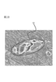
- FIG. 1A is an electron micrograph of a cross section of the fluororubber sheet produced in Example 2.
- FIG. 1B is an image in which an element mapping image is superimposed on an electron micrograph of a cross section of the fluororubber sheet produced in Example 2.
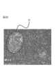
- FIG. 2A is an electron micrograph of a cross section of the fluororubber sheet produced in Comparative Example 1.
- FIG. 2B is an image in which an element mapping image is superimposed on an electron micrograph of a cross section of the fluororubber sheet produced in Comparative Example 1.
- the laminate of the present disclosure includes a fluororubber layer and a polymer layer.
- a fluororubber layer and a polymer layer.
- the fluororubber layer is a layer formed from a fluororubber composition.
- the fluororubber layer is usually obtained by molding a fluororubber composition to obtain an uncrosslinked fluororubber layer and then subjecting it to a cross-linking treatment.
- the fluororubber composition contains fluororubber, a basic polyfunctional compound, and polytetrafluoroethylene.
- Fluororubber is usually composed of an amorphous polymer having a fluorine atom bonded to a carbon atom constituting a main chain and having rubber elasticity.
- the fluororubber may be made of one kind of polymer or may be made of two or more kinds of polymers. Fluororubbers usually do not have a definite melting point.
- Fluoro rubber is a vinylidene fluoride (VdF) / hexafluoropropylene (HFP) copolymer, VdF / HFP / tetrafluoroethylene (TFE) copolymer, TFE / propylene copolymer, TFE / propylene / VdF copolymer.
- VdF vinylidene fluoride
- HFP hexafluoropropylene
- TFE tetrafluoroethylene
- the fluororubber is preferably a non-perfluorofluororubber, and more preferably a copolymer containing a polymerization unit (VdF unit) derived from vinylidene fluoride.
- the copolymer containing the VdF unit includes a VdF unit and a copolymerization unit derived from a fluorine-containing ethylenic monomer (however, the VdF unit is excluded. Hereinafter, it is also referred to as “fluorine-containing ethylene monomer unit (a)”. It is preferable that it is a copolymer containing.).
- the copolymer containing VdF units may be a copolymer consisting of only VdF units and a fluorine-containing ethylenic monomer unit (a), and further, VdF and a fluorine-containing ethylenic monomer (provided that the copolymer contains VdF and a fluorine-containing ethylene monomer unit (a)). VdF is excluded.
- it may be a copolymer containing a copolymerization unit derived from a monomer copolymerizable with "fluoroethylene-containing monomer (a)").
- the copolymer containing VdF unit 30 to 90 mol% of VdF unit and 70 to 10 mol% of fluorine are contained with respect to 100 mol% of the total of VdF unit and fluorine-containing ethylenic monomer unit (a). It preferably contains an ethylenically monomeric unit (a), more preferably 30 to 85 mol% of VdF units and 70 to 15 mol% of a fluoroethylene monomeric unit (a), and more preferably 30 to 15 mol%. It is more preferred to contain 80 mol% VdF units and 70-20 mol% fluoroethylene monomer units (a).
- the copolymerization unit derived from the monomer copolymerizable with VdF and the fluoroethylene monomer unit (a) (excluding the VdF unit) is the VdF unit and the fluoroethylene monomer (a). It is preferably 0 to 10 mol% with respect to the total amount of the derived copolymerization units.
- fluorine-containing ethylenic monomer (a) examples include TFE, CTFE, trifluoroethylene, HFP, trifluoropropylene, tetrafluoropropylene, pentafluoropropylene, trifluorobutene, tetrafluoroisobutene, PAVE and vinyl fluoride.
- General formula (1): CHX 1 CX 2 Rf 1 (1) (In the formula, X 1 and X 2 have H on one side and F on the other side, and Rf 1 is a linear or branched fluoroalkyl group having 1 to 12 carbon atoms), a general formula.
- CFX CXOCF 2 OR 1 (2)
- X represents the same or different, H, F or CF 3
- R 1 represents at least one atom selected from the group consisting of linear or branched H, Cl, Br and I. It may contain 1 to 2 fluoroalkyl groups having 1 to 6 carbon atoms, or 1 to 2 atoms of at least one selected from the group consisting of H, Cl, Br and I. Examples thereof include fluorine-containing monomers such as fluorovinyl ether represented by (representing a cyclic fluoroalkyl group having 5 or 6 carbon atoms).
- CH 2 CFCF 3 , preferably at least one selected from the group consisting of fluorovinyl ether represented by the formula (2), TFE, HFP and PAVE, and consisting of TFE, HFP and PAVE. More preferably, it is at least one selected from the group.
- CF 2 CFO (CF 2 CFY 1 O) p- (CF 2 CF 2 CF 2 O) q- Rf (3)
- Y 1 represents F or CF 3
- Rf represents a perfluoroalkyl group having 1 to 5 carbon atoms
- p represents an integer of 0 to 5
- q represents an integer of 0 to 5.
- the PAVE is more preferably perfluoro (methyl vinyl ether) or perfluoro (propyl vinyl ether), and even more preferably perfluoro (methyl vinyl ether). These can be used alone or in any combination.
- Examples of the monomer copolymerizable with VdF and the fluorine-containing ethylenic monomer (a) include ethylene, propylene, and alkyl vinyl ether.
- VdF / HFP copolymers examples include VdF / HFP copolymers, VdF / HFP / TFE copolymers, VdF / CTFE copolymers, VdF / CTFE / TFE copolymers, and VdF.
- the copolymers containing these VdF units at least one copolymer selected from the group consisting of VdF / HFP copolymers and VdF / HFP / TFE copolymers from the viewpoint of heat resistance. Is particularly preferable. It is preferable that the copolymer containing these VdF units satisfies the composition ratio of the above-mentioned VdF units and the fluorine-containing ethylenic monomer unit (a).
- the VdF / HFP copolymer preferably has a VdF / HFP molar ratio of 45 to 85/55 to 15, more preferably 50 to 80/50 to 20, and even more preferably 60 to 80/40. ⁇ 20.
- the molar ratio of VdF / HFP / TFE is preferably 30 to 85/5 to 50/5 to 40, and the molar ratio of VdF / HFP / TFE is 35 to 80/80. It is more preferably 8 to 45/8 to 35, further preferably the molar ratio of VdF / HFP / TFE is 40 to 80/10 to 40/10 to 30, and the molar ratio of VdF / HFP / TFE is. Most preferably, it is 40 to 80/10 to 35/10 to 30.
- the VdF / PAVE copolymer preferably has a VdF / PAVE molar ratio of 65 to 90/10 to 35.
- the VdF / TFE / PAVE copolymer preferably has a molar ratio of VdF / TFE / PAVE of 40 to 80/3 to 40/15 to 35.
- the VdF / HFP / PAVE copolymer preferably has a molar ratio of VdF / HFP / PAVE of 65 to 90/3 to 25/3 to 25.
- the VdF / HFP / TFE / PAVE copolymer preferably has a molar ratio of VdF / HFP / TFE / PAVE of 40 to 90/0 to 25/0 to 40/3 to 35, more preferably 40 to. It is 80/3 to 25/3 to 40/3 to 25.
- the fluororubber is composed of a copolymer containing a copolymer-derived copolymer derived from a monomer that provides a crosslinked site.
- the monomer that gives the cross-linking site include perfluoro (6,6-dihydro-6-iodo-3-oxa-1-) as described in JP-A-5-63482 and JP-A-7-316234.
- Iodine-containing monomers such as hexene) and perfluoro (5-iodo-3-oxa-1-pentene), bromine-containing monomers described in JP-A-4-505341A, JP-A-4-505345, Examples thereof include a cyano group-containing monomer, a carboxyl group-containing monomer, and an alkoxycarbonyl group-containing monomer as described in JP-A-5-500070.
- the fluororubber is also preferably a fluororubber having an iodine atom or a bromine atom at the end of the main chain.
- Fluororubbers having an iodine atom or a bromine atom at the end of the main chain are produced by emulsion polymerization of a monomer by adding a radical initiator in the presence of a halogen compound in an aqueous medium under substantially anoxic conditions. it can.
- halogen compound used include, for example, the general formula: R 2 I x Br y (In the formula, x and y are integers of 0 to 2 and satisfy 1 ⁇ x + y ⁇ 2, respectively, and R 2 is a saturated or unsaturated fluorohydrocarbon group having 1 to 16 carbon atoms and carbon. Saturated or unsaturated chlorofluorohydrocarbon groups of numbers 1 to 16, hydrocarbon groups of 1 to 3 carbon atoms, or cyclic hydrocarbon groups of 3 to 10 carbon atoms which may be substituted with iodine or bromine atoms. These include compounds represented by (which may contain an oxygen atom).
- halogen compound examples include 1,3-diiodoperfluoropropane, 1,3-diiod-2-chloroperfluoropropane, 1,4-diiodoperfluorobutane, and 1,5-diiod-2,4-.
- 1,4-diiodoperfluorobutane or diiodomethane is preferably used from the viewpoints of polymerization reactivity, cross-linking reactivity, availability, and the like.
- the fluorororubber preferably has a Mooney viscosity (ML 1 + 10 (100 ° C.)) of 5 to 200, preferably 10 to 150, from the viewpoint of good processability when producing a fluororubber composition. More preferably, it is more preferably 20 to 100. Mooney viscosity can be measured according to ASTM-D1646. Measuring equipment: MV2000E type rotor speed: 2 rpm manufactured by ALPHA TECHNOLOGIES Measurement temperature: 100 ° C
- the fluororubber composition preferably contains only the above-mentioned fluororubber as a rubber component.
- the fluororubber composition contains polytetrafluoroethylene (PTFE).
- the fluororubber layer provided in the laminate of the present disclosure is characterized by the fact that PTFE is dispersed in the fluororubber layer in the form of a single particle. Since the fluororubber layer has such characteristics, in the laminate of the present disclosure, the fluororubber layer and the polymer layer are adhered with sufficient adhesive strength, and the fluororubber layer is formed when the fluororubber is crosslinked. Shrinkage can be suppressed.
- the shape of fluororubber is not regulated.
- the shrinkage of the fluororubber layer is particularly large when the fluororubber is molded and crosslinked without using a mold, for example, when the fluororubber is extruded and then the obtained extrusion is crosslinked by heating. Observed.
- PTFE is dispersed in the fluororubber layer in the form of single particles, shrinkage during cross-linking is suppressed even in the fluororubber layer formed by extrusion molding.
- FIGS. 2A and 2B are electron micrographs of a cross section of the fluororubber sheet produced in Comparative Example 1 and show the dispersed state in the fluororubber layer containing PTFE included in the conventional laminate.
- the fluororubber layer included in the laminate of one embodiment of the present disclosure contains PTFE dispersed in the fluororubber, and the cross section of the PTFE is observed. This confirms that it is a single particle.
- the fluororubber layer provided in the conventional laminate also contains PTFE dispersed in the fluororubber, but when the cross section of the PTFE in the fluororubber is observed, , A large number of microparticles that are bound to each other via elongated branches can be confirmed.
- the PTFE dispersed in the fluororubber is not dispersed in the state of agglomerated fine particles unlike the conventional laminate, and the PTFE is a single particle in the fluororubber layer. Since it is dispersed in the state, it is possible to suppress the shrinkage of the fluororubber layer when the fluororubber is crosslinked.
- the fluororubber layer included in the laminate of the present disclosure is characterized by having a specific surface area of PTFE contained in the fluororubber layer of less than 8 m 2 / g. Since the fluororubber layer has such characteristics, in the laminate of the present disclosure, the fluororubber layer and the polymer layer are adhered with sufficient adhesive strength, and the fluororubber layer is formed when the fluororubber is crosslinked. Shrinkage can be suppressed.
- the specific surface area of PTFE contained in the fluororubber layer is preferably 7.0 m 2 / g or less, more preferably 6.0 m 2 / g or less, and further preferably 5.2 m 2 / g or less. Even more preferably 4.0 m 2 / g or less, particularly preferably 3.0 m 2 / g or less, most preferably 2.5 m 2 / g or less, preferably 0.5 m 2 / g or more. It is more preferably 1.0 m 2 / g or more, and further preferably 1.4 m 2 / g or more.
- a surface analyzer (trade name: BELSORP-miniII, manufactured by Microtrac Bell), use a mixed gas of 30% nitrogen and 70% helium as the carrier gas, and use liquid nitrogen for cooling, BET. Measure by method.
- the specific surface area of PTFE can be adjusted within the above range by adjusting the polymerization conditions of TFE when producing PTFE. For example, by producing PTFE by suspension polymerization or heat-treating it, PTFE having a specific surface area within the above range can be easily produced. Further, by using PTFE having a specific surface area within the above range, PTFE can be easily dispersed in the fluororubber in the state of a single particle.
- PTFE has melt processability.
- the melt viscosity of PTFE at 380 ° C. is preferably 1 ⁇ 10 1 to 7 ⁇ 10 5 Pa ⁇ s.
- a PTFE having a melt viscosity within the above range has a low molecular weight, for example, a PTFE having a number average molecular weight of 600,000 or less.
- "Ultra-high molecular weight PTFE” having a number average molecular weight of more than 600,000 exhibits fibrillation characteristics peculiar to PTFE (see, for example, Japanese Patent Application Laid-Open No. 10-147617).
- High molecular weight PTFE has a high melt viscosity and is non-melt processable. It is preferable that the PTFE contained in the fluororubber layer does not exhibit fibrillation characteristics to the extent that paste extrusion molding is possible.
- the melt viscosity and number average molecular weight of PTFE can be adjusted by adjusting the polymerization conditions of TFE when producing PTFE or by irradiating PTFE with an electron beam.
- the melt viscosity conforms to ASTM D1238, and a 2 g sample preheated at 380 ° C. for 5 minutes using a flow tester (manufactured by Shimadzu Corporation) and a 2 ⁇ -8L die under a load of 0.7 MPa. It is a value measured while maintaining the above temperature.
- the number average molecular weight is a value calculated from each of the melt viscosities measured by the above measuring method.
- the apparent density of PTFE is preferably 0.15 to 0.80 g / cm 3 , and more preferably 0.25 to 0.55 g / cm 3 .
- the apparent density can be measured in accordance with JIS K 6891.
- the average particle size of PTFE is preferably 0.01 to 1000 ⁇ m, more preferably 0.1 to 100 ⁇ m, still more preferably 0.3 to 50 ⁇ m, and particularly preferably 0.5 to 20 ⁇ m. ..
- the average particle size was obtained by measuring the particle size distribution using a laser diffraction type particle size distribution measuring device (for example, manufactured by Nippon Laser Co., Ltd.) at a pressure of 0.1 MPa and a measurement time of 3 seconds without using a cascade.
- the value corresponding to 50% of the integration is defined as the average particle size.
- the melting point of PTFE is preferably 324 to 333 ° C.
- the melting point of PTFE is made of aluminum with about 3 mg of PTFE powder after temperature calibration using differential scanning calorimetry RDC220 (DSC) manufactured by SII Nanotechnology Co., Ltd. using indium and lead as standard samples in advance. Put it in a pan (crimp container), raise the temperature range of 250 to 380 ° C at 10 ° C / min under an air flow of 200 ml / min, measure the differential scanning calorimetry, and determine the minimum point of the heat of fusion in the above range. Let it be the melting point.
- DSC differential scanning calorimetry
- the melt flow rate (MFR) of PTFE at 372 ° C. (load 1.2 kg) is preferably 0.01 to 10 g / 10 minutes.
- the MFR uses a melt indexer (for example, manufactured by Toyo Seiki Seisakusho Co., Ltd.), and the weight (g) of the polymer flowing out from a nozzle having a diameter of 2 mm and a length of 8 mm at 372 ° C. under a load of 1.2 kg per unit time (10 minutes). ) Can be identified by measuring.
- a melt indexer for example, manufactured by Toyo Seiki Seisakusho Co., Ltd.
- the burning weight loss (ignition weight loss) of PTFE at 300 ° C. is preferably 0.05% by mass or more, more preferably 0.09% by mass or more, because the shrinkage of the fluororubber layer can be further suppressed. It is more preferably 0.15% by mass or more, and particularly preferably 0.30% by mass or more.
- Burning weight loss is specified by heating PTFE (sample) at 300 ° C. for 2 hours, measuring the mass of the sample after heating, and calculating the ratio of weight loss of the sample after heating to the mass of the sample before heating. it can.
- the PTFE may be a homopolymer of TFE, or may be a modified PTFE containing a TFE unit and a modified monomer unit copolymerizable with TFE.
- the content of the modified monomer unit copolymerizable with TFE of the modified PTFE is preferably 0.01 to 1% by mass, more preferably 0.01 to 0.5% by mass, based on all the monomer units. It is preferably 0.03 to 0.3% by mass, most preferably 0.03 to 0.3% by mass.
- the modified monomer unit means a part of the molecular structure of the modified PTFE and derived from the modified monomer, and the total monomer unit means all the monomers in the molecular structure of the modified PTFE. It means the part from which it is derived.
- the content of the modified monomer unit is a value measured by infrared spectroscopic analysis or NMR (nuclear magnetic resonance).
- the modified monomer in the modified PTFE is not particularly limited as long as it can be copolymerized with TFE, and is, for example, a perfluoroolefin such as hexafluoropropylene [HFP]; a chlorofluoroethylene such as chlorotrifluoroethylene [CTFE]. Olefins; hydrogen-containing fluoroolefins such as trifluoroethylene and vinylidene fluoride [VDF]; perfluorovinyl ethers; perfluoroalkylethylene: ethylene and the like. Further, the modified monomer used may be one kind or a plurality of kinds.
- Rf represents a perfluoroorganic group.
- perfluoroorganic group means an organic group in which all hydrogen atoms bonded to carbon atoms are replaced with fluorine atoms.
- the perfluoroorganic group may have ether oxygen.
- perfluorovinyl ether examples include perfluoro (alkyl vinyl ether) [PAVE] in which Rf represents a perfluoroalkyl group having 1 to 10 carbon atoms in the general formula (I). The number of carbon atoms of the perfluoroalkyl group is preferably 1 to 5.
- Examples of the perfluoroalkyl group in PAVE include a perfluoromethyl group, a perfluoroethyl group, a perfluoropropyl group, a perfluorobutyl group, a perfluoropentyl group, a perfluorohexyl group, and the like.
- Purple olopropyl vinyl ether [PPVE] in which the group is a perfluoropropyl group is preferable.
- Rf is a perfluoro (alkoxyalkyl) group having 4 to 9 carbon atoms, and Rf is the following formula:
- Rf is the following formula:
- n an integer of 1 to 4
- n represents an integer of 1 to 4
- the perfluoroalkylethylene is not particularly limited, and examples thereof include perfluorobutylethylene (PFBE), perfluorohexylethylene, and perfluorooctylethylene.
- PFBE perfluorobutylethylene
- PFBE perfluorohexylethylene
- perfluorooctylethylene perfluorooctylethylene
- the modified monomer in the modified PTFE at least one monomer selected from the group consisting of HFP, CTFE, VDF, PPVE, PFBE and ethylene is preferable, and HFP is more preferable.
- the PTFE is preferably a modified PTFE, and more preferably a modified PTFE containing a TFE unit and a polymerization unit (HFP unit) derived from HFP.
- HFP unit polymerization unit
- the content of PTFE in the fluororubber composition is preferably 0.5 to 100 parts by mass with respect to 100 parts by mass of the fluororubber because the fluororubber layer and the polymer layer adhere more firmly. It is preferably 10 parts by mass or more, more preferably 20 parts by mass or more, more preferably 80 parts by mass or less, further preferably 60 parts by mass or less, and particularly preferably 45 parts by mass or less.
- the fluororubber composition contains a basic polyfunctional compound, which allows the fluororubber layer and the polymer layer to adhere more firmly.
- a basic polyfunctional compound is a compound that has two or more functional groups having the same or different structures in one molecule and exhibits basicity.
- R 1 and R 2 are independently organic groups having 0 to 12 carbon atoms)
- -NR 3 R 4 in the formula, R 3 and R 4 are independently having 0 to 12 carbon atoms
- -NR 3 R 4 R 5 in the formula, R 3 , R 4 and R 5 are independently organic groups with 0-12 carbon atoms
- the number of functional groups contained in the polyfunctional compound is not particularly limited as long as it is 2 or more, but is preferably 2 to 8, more preferably 2 to 4, still more preferably 2 or 3, and particularly preferably. It is 2.
- R 1 , R 2 , R 3 , R 4 and R 5 are preferably ⁇ H or an organic group having 1 to 12 carbon atoms independently, and —H or 1 to 12 carbon atoms. It is preferably a hydrocarbon group of.
- the hydrocarbon group may have one or more carbon-carbon double bonds.
- the hydrocarbon group preferably has 1 to 8 carbon atoms.
- R 1 is -H or -CH 3
- R 6 is a phenyl group (-C 6 H 5 ), a benzyl group (-CH 2- C 6 H 5).
- Examples of the basic polyfunctional compound include ethylenediamine, propanediamine, putresin, cadaberin, hexamethylenediamine, heptanediamine, octanediamine, nonanediamine, decanediamine, undecanediamine, dodecanediamine, phenylenediamine, N, N'-dicinnamylidene-. 1,6-Hexamethylenediamine, N, N, N', N'-tetramethyl-1,6-hexamethylenediamine, N, N'-dimethyl-1,6-hexamethylenediamine, 6-aminohexylcarbamide acid And so on.
- the basic polyfunctional compound contains at least two nitrogen atoms in the molecule and the interatomic distance between nitrogen and nitrogen is 5.70 ⁇ or more.
- the interatomic distance between nitrogen and nitrogen is more preferably 6.30 ⁇ or more, further preferably 7.60 ⁇ or more, and particularly preferably 8.60 ⁇ or more.
- the wide interatomic distance between nitrogen increases the flexibility of the basic polyfunctional compound and facilitates cross-linking.
- the interatomic distance between nitrogen and nitrogen is calculated according to the following method. That is, the structure optimization of each base is calculated using the density functional theory (program is Gaussian03, density functional is B3LYP, basis function is 6-31G *).
- the basic polyfunctional compounds include N, N'-dicinnamylidene-1,6-hexamethylenediamine and NH 2- (CH 2 ) n- NH 2 (CH 2) n-NH 2 (in terms of adhesiveness between the fluororubber layer and the polymer layer.
- n is preferably at least one selected from the group consisting of 5 to 12), and at least selected from the group consisting of hexamethylenediamine and N, N'-dicinnamilyden-1,6-hexamethylenediamine.
- One is more preferable.
- the content of the basic polyfunctional compound is preferably 0.5 parts by mass with respect to 100 parts by mass of the fluororubber because the fluororubber layer and the polymer layer adhere more firmly.
- the above is more preferably 0.6 parts by mass or more, further preferably 0.8 parts by mass or more, particularly preferably 1.0 part by mass or more, and most preferably 1.5 parts by mass or more. is there.
- the content of the basic polyfunctional compound is preferably 10 parts by mass or less, more preferably 6 parts by mass or less, and further preferably 6 parts by mass or less from the viewpoint of cross-linking inhibition and cost. It is 5 parts by mass or less, and particularly preferably 3 parts by mass or less.
- the fluororubber composition contains at least one selected from the group consisting of a phosphorus compound and silica.
- the fluororubber composition may contain a phosphorus compound.
- the fluororubber composition contains a phosphorus compound, the fluororubber layer and the polymer layer are more firmly adhered to each other.
- the phosphorus compound is a compound containing at least one phosphorus atom in one molecule, and examples thereof include phosphines, phosphoric acid esters, phosphazenes, phosphine oxides, phosphonic acid esters, and phosphinic acid esters.
- the general formula: PR 3 (in the formula, three Rs represent the same or different halogen atom or organic group). At least one selected from the group consisting of the represented phosphine compound, phosphonium salt, and phosphine oxides is preferable, and the above phosphine compound is more preferable.
- the phosphine compound is represented by the general formula: PR 3 , and the three Rs in the formula may be the same or different, and represent a halogen atom or an organic group, respectively.
- the above phosphine compound, triphenylphosphine hydrochloride, triphenylphosphine borane, triphenylphosphine - compound comprising a structure represented by PR 3, such as triphenyl borane complexes are also included.
- Examples of the organic group include hydrocarbon groups having 1 to 30 carbon atoms which may have a substituent.
- the hydrocarbon group may be linear, branched, monocyclic or polycyclic, may have an unsaturated bond, may be aromatic, and may contain a heteroatom.
- Examples of the substituent include an alkoxy group, an amino group, a cyano group, an aldehyde group, a carboxylic acid group, a halogen atom, a phosphine group, a phosphone group, a diphenylphosphino group and the like.
- Examples of the phosphine compound include the following compounds.
- phosphine compound any of the following compounds is preferable.
- the phosphine compound one kind or two or more kinds can be used.
- a quaternary phosphonium salt is preferable, for example, tetrabutylphosphonium chloride, benzyltriphenylphosphonium chloride, benzyltrimethylphosphonium chloride, benzyltributylphosphonium chloride, tributylallylphosphonium chloride, tributyl-2-methoxypropylphosphonium chloride. , Benzylphenyl (dimethylamino) phosphonium chloride, tributyl (cyanomethyl) phosphonium chloride and the like.
- Examples of the organic group include hydrocarbon groups having 1 to 30 carbon atoms which may have a substituent.
- the hydrocarbon group may be linear, branched, monocyclic or polycyclic, may have an unsaturated bond, may be aromatic, and may contain a heteroatom.
- Examples of the substituent include an alkoxy group, an amino group, a cyano group, an aldehyde group, a carboxylic acid group, a halogen atom, a phosphine group, a phosphone group, a diphenylphosphino group and the like.
- the following compounds are preferable.
- the content of the phosphorus compound in the fluororubber composition is preferably 0.01 to 20 parts by mass with respect to 100 parts by mass of the fluororubber because the fluororubber layer and the polymer layer adhere more firmly. It is more preferably 0.05 to 10 parts by mass, further preferably 0.1 to 5 parts by mass, particularly preferably 0.2 to 3 parts by mass, and most preferably 0.2 to 1 part by mass. is there.
- the fluororubber composition may contain silica.
- silica basic silica and acidic silica can be used, and it is preferable to use basic silica from the viewpoint of adhesiveness.
- the basic silica include Carplex 1120 (manufactured by DSL Japan), Sidestar R300 (manufactured by Elchem), Sirene732D (manufactured by PPG Industries), and Inhibisil75 (manufactured by PPG Industries).
- silica having a large average particle size examples include Sidestar R300 (manufactured by Elchem), Sidestar T120U (manufactured by Elchem), Admafine series (manufactured by Admatex), and Celica series (manufactured by Tokuyama).
- the content of silica in the fluororubber composition is preferably 5 to 100 parts by mass, more preferably 5 to 100 parts by mass, with respect to 100 parts by mass of the fluororubber because the fluororubber layer and the polymer layer adhere more firmly. It is 10 to 70 parts by mass, more preferably 15 to 50 parts by mass, and most preferably 15 to 30 parts by mass.
- the fluororubber composition further contains a cross-linking agent because the fluororubber layer and the polymer layer are more firmly adhered to each other.
- a cross-linking agent a peroxide cross-linking agent or the like can be selected according to the purpose.
- the fluororubber composition preferably contains a peroxide cross-linking agent.
- the peroxide cross-linking agent is not particularly limited, and examples thereof include organic peroxides.
- organic peroxide those that easily generate peroxy radicals in the presence of heat or an oxidation-reduction system are preferable, and for example, 1,1-bis (t-butylperoxy) -3,5,5-trimethyl Cyclohexane, 2,5-dimethylhexane-2,5-dihydroxyperoxide, di-t-butylperoxide, t-butylcumylperoxide, dicumylperoxide, ⁇ , ⁇ '-bis (t-butylperoxy) -P-diisopropylbenzene, 2,5-dimethyl-2,5-di (t-butylperoxy) hexane, 2,5-dimethyl-2,5-di (t-butylperoxy) hexin-3, benzoylper Examples thereof include oxide, t-butylperoxybenzene, 2,5-di
- the amount of the peroxide cross-linking agent used is appropriately selected from the amount of activity-O-O-, the decomposition temperature, and the like.
- the content of the peroxide cross-linking agent in the fluororubber composition is usually 0.1 to 15 parts by mass, preferably 0.3 to 5 parts by mass, more preferably with respect to 100 parts by mass of the fluororubber. Is 1 to 4 parts by mass, more preferably 1 to 2 parts by mass.
- the fluororubber composition preferably contains a cross-linking aid.
- the cross-linking aid include triallyl cyanurate, trimetalyl isocyanurate, triallyl isocyanurate (TAIC), triallylic formal, triallyl trimellitate, N, N'-m-phenylene bismaleimide, and dipropagil.
- the content of the cross-linking aid in the fluororubber composition is preferably 0.2 to 10 parts by mass, more preferably 0.5 to 9 parts by mass, still more preferably, with respect to 100 parts by mass of the fluororubber. Is 2 to 8 parts by mass, most preferably 3 to 7 parts by mass.
- the fluororubber composition is used as an acid receiving agent or as a compounding agent for improving the adhesiveness between the fluororubber layer and the polymer layer, as a metal oxide, a metal hydroxide, a weak acid salt of an alkali metal, and an alkaline soil. It may contain at least one compound selected from the group consisting of weak acid salts of similar metals.
- metal oxides, metal hydroxides, alkali metal weak salts and alkaline earth metal weak acid salts include oxides, hydroxides, carbonates, carboxylates and silicates of Group (II) metal of the periodic table.
- examples thereof include acid salts, borates, phosphites, oxides of Group (IV) metal of the periodic table, basic carbonates, basic carboxylic acid salts, basic sulphates, and basic sulfites. ..
- metal oxides, metal hydroxides, alkali metal weak salts and alkaline earth metal weak salts include magnesium oxide, zinc oxide, magnesium hydroxide, barium hydroxide, magnesium carbonate, barium carbonate, etc.
- examples thereof include calcium oxide (quick lime), calcium hydroxide (slaked lime), calcium carbonate, calcium silicate, calcium stearate, zinc stearate, calcium phthalate, calcium phosphite, tin oxide, and basic tin phosphite.
- the content of the metal oxide, the metal hydroxide, the weak acid salt of the alkali metal, and the weak acid salt of the alkaline earth metal is preferably 5 parts by mass or less. , More preferably 3 parts by mass or less, and further preferably not contained from the viewpoint of acid resistance.
- the fluororubber composition is a usual additive to be blended in the fluororubber composition as needed, for example, a filler, a processing aid, a plasticizer, a colorant, a stabilizer, an adhesive aid, and an acid receiving agent. , Mold release agent, conductivity imparting agent, thermal conductivity imparting agent, surface non-adhesive agent, flexibility imparting agent, heat resistance improving agent, flame retardant, and various other additives can be blended. It may contain one or more different commonly used cross-linking agents and cross-linking accelerators.
- Examples of the filler include carbon black.
- the content of carbon black is preferably 0 to 100 parts by mass, more preferably 2 to 60 parts by mass, still more preferably 5 to 40 parts by mass, and particularly preferably 5 to 40 parts by mass with respect to 100 parts by mass of the fluororubber. Is 10 to 30 parts by mass.
- the use of carbon black has the advantage of improving mechanical properties and heat resistance.
- the fluororubber composition can be obtained by kneading each component using a commonly used rubber kneading device.
- a rubber kneading device a roll, a kneader, a Banbury mixer, an internal mixer, a twin-screw extruder and the like can be used.
- the polymer layer is a layer different from the fluororubber layer and is formed from a polymer (excluding fluororubber).
- the polymer forming the polymer layer may be resin or rubber (excluding fluororubber), but resin is preferable.
- the rubber examples include acrylonitrile-butadiene rubber (NBR) or a hydride thereof (HNBR), styrene-butadiene rubber (SBR), chloroprene rubber (CR), butadiene rubber (BR), natural rubber (NR), and isoprene rubber (Diene rubber such as IR), ethylene-propylene-ter monomer copolymer rubber, silicone rubber, butyl rubber, epichlorohydrin rubber, acrylic rubber, chlorinated polyethylene (CPE), acrylonitrile-butadiene rubber and vinyl chloride polyblend ( PVC-NBR), ethylene propylene diene rubber (EPDM), chlorosulfonated polyethylene (CSM) and the like.
- NBR acrylonitrile-butadiene rubber
- HNBR hydride thereof
- SBR styrene-butadiene rubber
- CR chloroprene rubber
- BR butadiene rubber
- NR natural rubber
- the resin examples include fluororesins, polyamide resins, polyolefin resins, vinyl chloride resins, polyurethane resins, polyester resins, polyaramid resins, polyimide resins, polyamideimide resins, polyphenylene oxide resins, polyacetal resins, polycarbonate resins, and acrylic resins.
- Resin styrene resin, acrylonitrile / butadiene / styrene resin (ABS), cellulose resin, polyether ether ketone resin (PEEK), polysulfone resin, polyethersulfone resin (PES), polyetherimide resin, ethylene / vinyl alcohol
- PEEK polyether ether ketone resin
- PES polyethersulfone resin
- PPA polyphthalamide
- fluororesin is preferable because it is excellent in chemical resistance, low fuel permeability, and the like.
- the fluororesin preferably has a low fuel permeability coefficient.
- the fuel permeation coefficient of the fluororesin is preferably 2.0 g ⁇ mm / m 2 / day or less, more preferably 1.5 g ⁇ mm / m 2 / day or less, and even more preferably 0.8 g ⁇ mm. It is / m 2 / day or less, particularly preferably 0.55 g ⁇ mm / m 2 / day or less, and most preferably 0.5 g ⁇ mm / m 2 / day or less.
- the polymer layer contains a fluororesin having a fuel permeability coefficient within the above range, the polymer layer exhibits excellent fuel low permeability, and the laminate can be suitably used as a fuel hose or the like.
- the fuel permeation coefficient was measured in a SUS316 fuel permeation coefficient measuring cup having an inner diameter of 40 mm ⁇ and a height of 20 mm containing 18 mL of an isooctane / toluene / ethanol mixed solvent in which isooctane, toluene and ethanol were mixed at a volume ratio of 45:45:10. It is a value calculated from the mass change measured at 60 ° C. by incorporating a fluororesin sheet (diameter 45 mm, thickness 120 ⁇ m) prepared from the measurement target resin by the following method.
- PCTFE polychlorotrifluoroethylene
- CTFE-based copolymers TFE / HFP / VdF copolymers.
- TFE / HFP / VdF copolymers At least one selected is preferable, and at least one selected from the group consisting of polychlorotrifluoroethylene (PCTFE) and CTFE-based copolymers is more preferable, and CTFE-based from the viewpoint of low fuel permeability and flexibility. Copolymers are more preferred.
- monomers include perfluoro (methyl vinyl ether), perfluoro (ethyl vinyl ether), perfluoro (propyl vinyl ether), chlorotrifluoroethylene, 2-chloropentafluoropropene, and perfluorinated vinyl ether (eg CF 3 OCF).
- PCTFE is a homopolymer of chlorotrifluoroethylene.
- Monomer represented by 4 in the formula, X 3 is H or F, X 4 is H, F or Cl, n is an integer of 1 to 10), ethylene, propylene, 1-butene, 2-butene, It preferably contains vinyl chloride and a copolymerization unit derived from at least one monomer selected from the group consisting of vinylidene chloride. Further, the CTFE-based copolymer is more preferably
- the CTFE-based copolymer more preferably contains a CTFE unit and a copolymerization unit derived from at least one monomer selected from the group consisting of TFE, HFP and PAVE, and substantially these. It is more preferable that it comprises only the copolymerization unit of. Further, from the viewpoint of low fuel permeability, it is preferable not to contain a monomer having a CH bond such as ethylene, vinylidene fluoride, and vinyl fluoride.
- a monomer-free perhalopolymer having a CH bond is usually difficult to adhere to a fluororubber, but according to the configuration of the present disclosure, even when the polymer layer contains a perhalopolymer, the fluororubber layer The adhesion between the layer and the polymer layer is strong.
- the CTFE-based copolymer preferably has 10 to 90 mol% of CTFE units of all monomer units.
- CTFE-based copolymer those containing a CTFE unit, a TFE unit, and a monomer ( ⁇ ) unit derived from a monomer ( ⁇ ) copolymerizable with these are particularly preferable.
- CTFE unit and "TFE unit”, the molecular structure of the CTFE copolymer, respectively, portions derived from CTFE (-CFCl-CF 2 -) , moieties derived from TFE (-CF 2 -CF 2 - ), And the "monomer ( ⁇ ) unit” is similarly a portion to which the monomer ( ⁇ ) is added due to the molecular structure of the CTFE-based copolymer.
- Rf 2 is a perfluoroalkyl group having 1 to 8 carbon atoms) PAVE
- CX 5 X 6 CX 7 (CF 2 ) n X 8 (In the formula, X 5 , X 6 and X 7 are the same.
- the monomer ( ⁇ ) is preferably at least one selected from the group consisting of PAVE, the above-mentioned vinyl monomer, and an alkyl perfluorovinyl ether derivative, and more preferably than the group consisting of PAVE and HFP. It is more preferably at least one selected, and PAVE is particularly preferable.
- the ratio of the CTFE unit to the TFE unit in the CTFE-based copolymer is 15 to 90 mol% for the CTFE unit and 85 to 10 mol% for the TFE unit, more preferably 20 to 90 mol% for the CTFE unit. %, And the TFE unit is 80-10 mol%. Further, those composed of 15 to 25 mol% of CTFE units and 85 to 75 mol% of TFE units are also preferable.
- the total of CTFE units and TFE units of the CTFE-based copolymer is 90 to 99.9 mol%, and the monomer ( ⁇ ) unit is preferably 0.1 to 10 mol%. If the monomer ( ⁇ ) unit is less than 0.1 mol%, the moldability, environmental stress cracking resistance and fuel cracking resistance are likely to be inferior, and if it exceeds 10 mol%, fuel low permeability and heat resistance, It tends to be inferior in mechanical properties.
- At least one selected from the group consisting of PCTFE, CTFE / TFE / PAVE copolymer and TFE / HFP / VdF copolymer is more preferable from the viewpoint of low fuel permeability and adhesiveness, and CTFE is more preferable.
- At least one selected from the group consisting of / TFE / PAVE copolymers and TFE / HFP / VdF copolymers is more preferable, and CTFE / TFE / PAVE copolymers are particularly preferable.
- the CTFE / TFE / PAVE copolymer is a copolymer consisting substantially only of CTFE, TFE and PAVE.
- the above-mentioned PAVE includes perfluoro (methyl vinyl ether) (PMVE), perfluoro (ethyl vinyl ether) (PEVE), perfluoro (propyl vinyl ether) (PPVE), and perfluoro (butyl vinyl ether). ), Etc., and among them, at least one selected from the group consisting of PMVE, PEVE and PPVE is preferable.
- the PAVE unit is preferably 0.5 mol% or more and preferably 5 mol% or less of all the monomer units.
- Constituent units such as CTFE units are values obtained by performing 19 F-NMR analysis.
- the fluororesin is obtained by introducing at least one reactive functional group selected from the group consisting of a carbonyl group, a hydroxyl group, a heterocyclic group, and an amino group into the main chain terminal and / or side chain of the polymer. You may.
- the hydrogen atom bonded to the nitrogen atom may be substituted with a hydrocarbon group such as an alkyl group. ..
- Reactive functional groups are amide groups, carbamoyl groups, hydroxyl groups, carboxyl groups, and carbonate groups because they are easy to introduce and the fluororesin has appropriate heat resistance and good adhesion at relatively low temperatures.
- Carboxylic acid halide group, acid anhydride bond is preferable, and further, amide group, carbamoyl group, hydroxyl group, carbonate group, carboxylic acid halide group and acid anhydride bond are preferable.
- Fluororesin can be obtained by conventionally known polymerization methods such as suspension polymerization, solution polymerization, emulsion polymerization and bulk polymerization. In the polymerization, each condition such as temperature and pressure, the polymerization initiator and other additives can be appropriately set according to the composition and amount of the fluororesin.
- the melting point of the fluororesin is not particularly limited, but is preferably 160 to 270 ° C.
- the melting point of the fluororesin is determined as a temperature corresponding to the maximum value in the heat of fusion curve when the temperature is raised at a rate of 10 ° C./min using a DSC device (manufactured by Seiko Co., Ltd.).
- the molecular weight of the fluororesin is preferably in a range in which the obtained laminate can exhibit good mechanical properties, low fuel permeability, and the like.
- melt flow rate MFR
- the MFR at an arbitrary temperature in the range of about 230 to 350 ° C. which is the general molding temperature range of fluororesin, is preferably 0.5 to 100 g / 10 minutes. It is more preferably 1 to 50 g / 10 minutes, and even more preferably 2 to 35 g / 10 minutes.
- the fluororesin is a PCTFE, CTFE-based copolymer or TFE / HFP / VdF copolymer
- the MFR is measured at 297 ° C.
- the MFR uses a melt indexer (manufactured by Toyo Seiki Seisakusho Co., Ltd.) to determine the weight (g) of the polymer flowing out from a nozzle having a diameter of 2 mm and a length of 8 mm in a unit time (10 minutes) at 297 ° C. under a load of 5 kg. It can be identified by measuring.
- a melt indexer manufactured by Toyo Seiki Seisakusho Co., Ltd.
- the polymer layer may contain one kind of these fluororesins, or may contain two or more kinds of these fluororesins.
- a perhalopolymer is a polymer in which halogen atoms are bonded to all of the carbon atoms constituting the main chain of the polymer.
- the polymer layer may further contain various fillers such as inorganic powder, glass fiber, carbon powder, carbon fiber, and metal oxide, depending on the purpose and application, as long as the performance is not impaired. ..
- smectite-based layered viscosity minerals such as montmorillonite, biderite, saponite, nontronite, hectorite, saponite, and stibunsite, and microlayer minerals with a high aspect ratio such as mica are used. It may be added.
- a conductive filler may be added in order to impart conductivity.
- the conductive filler is not particularly limited, and examples thereof include a conductive single powder such as metal and carbon or a conductive single fiber; a powder of a conductive compound such as zinc oxide; and a surface conductive treated powder.
- a conductive single powder such as metal and carbon or a conductive single fiber
- a powder of a conductive compound such as zinc oxide
- a surface conductive treated powder When the conductive filler is blended, it is preferable to prepare pellets in advance by melt-kneading.
- the conductive single powder or the conductive single fiber is not particularly limited, and is described in, for example, a metal powder such as copper and nickel; a metal fiber such as iron and stainless steel; carbon black, carbon fiber, JP-A-3-174018 and the like. Carbon fibrils and the like.
- the surface conductive treatment powder is a powder obtained by subjecting the surface of a non-conductive powder such as glass beads or titanium oxide to a conductive treatment.
- the method of surface conductivity treatment is not particularly limited, and examples thereof include metal sputtering and electroless plating.
- carbon black is preferably used because it is advantageous from the viewpoint of economy and prevention of static charge accumulation.
- the volume resistivity of the fluororesin composition was formed by blending a conductive filler is preferably 1 ⁇ 10 0 ⁇ 1 ⁇ 10 9 ⁇ ⁇ cm.
- a more preferable lower limit is 1 ⁇ 10 2 ⁇ ⁇ cm, and a more preferable upper limit is 1 ⁇ 10 8 ⁇ ⁇ cm.
- a heat stabilizer In addition to the filler, a heat stabilizer, a reinforcing agent, an ultraviolet absorber, a pigment, and any other additive may be blended.
- the thickness of the fluororubber layer is not limited, but is preferably 100 ⁇ m or more, for example.
- the upper limit of the thickness of the fluororubber layer is, for example, 5000 ⁇ m.
- the thickness of the polymer layer is not limited, but is preferably 10 ⁇ m or more, for example.
- the upper limit of the thickness of the polymer layer is, for example, 1000 ⁇ m.
- the adhesive strength between the fluororubber layer and the polymer layer in the laminate is preferably 7 N / cm or more, more preferably 11 N / cm or more, still more preferably 12 N / cm or more, and particularly preferably 15 N / cm or more. It is cm or more.
- the adhesive strength is within the above range, there are advantages that the hose is less likely to be displaced when the hose is crosslinked with a specific shape, and that the hose is not peeled off when an impact is applied.
- the laminated body of the present disclosure can have the adhesive strength in the above-mentioned range.
- the adhesive strength is determined by cutting the laminate into strips of width 10 mm x length 40 mm x 3 sets to prepare a sample piece, and for this test piece, the effect of the adhesive strength on the interface between the fluororubber layer and the polymer layer.
- the interface between the fluororubber layer and the polymer layer is slowly pulled once by hand to increase the grip margin by 2 to 3 mm, and then Autograph (Shimadzu Seisakusho Co., Ltd.) AGS-J 5kN) is used to perform a peeling test at a tensile speed of 50 mm / min at 25 ° C. in accordance with the method described in JIS-K-6256 (adhesion test method for fluoropolymer), and a peeling mode is performed. It is a value to be measured by observing.
- the fluororubber layer and the polymer layer are preferably directly bonded, and more preferably directly crosslinked.
- a laminate can be obtained by laminating an uncrosslinked fluororubber layer and a polymer layer and then subjecting them to crosslinking.
- the laminate of the present disclosure may be a crosslinked laminate.
- cross-linking treatment conventionally known cross-linking methods and conditions for fluorororubber compositions can be adopted.
- a method of cross-linking an uncrosslinked laminate for a long time a method of heat-treating an uncrosslinked laminate as a pretreatment in a relatively short time (crosslinking has also occurred), and then a method of performing crosslinking over a long period of time is there.
- the method in which the uncrosslinked laminate is heat-treated as a pretreatment in a relatively short time and then crosslinked over a long period of time facilitates the adhesion between the fluororubber layer and the polymer layer in the pretreatment.
- various methods for holding the laminate in the subsequent crosslinking can be selected, which is preferable.
- the conditions of the cross-linking treatment are not particularly limited and can be carried out under normal conditions, but at 140 to 180 ° C. for 2 to 80 minutes, steam, press, oven, air bath, infrared rays, microwaves, subject. It is preferable to carry out the treatment using lead cross-linking or the like. More preferably, it is carried out at 150 to 170 ° C. for 5 to 60 minutes.
- the cross-linking treatment may be divided into a primary cross-linking and a secondary cross-linking.
- the laminate of the present disclosure is, for example, a step of mixing a fluororubber, a basic polyfunctional compound, and polytetrafluoroethylene to obtain a fluororubber composition, and is not obtained by molding the above-mentioned fluororubber composition. It can be preferably produced by a method for producing a laminated body, which includes a step of laminating the crosslinked fluororubber layer and the polymer layer, and a step of crosslinking the laminated uncrosslinked fluororubber layer and the polymer layer. In the above production method, the conditions of the crosslinking treatment are the same as those described above.
- fluororubber, basic polyfunctional compound, and polytetrafluoroethylene are, for example, rubber kneading of fluororubber, basic polyfunctional compound, and polytetrafluoroethylene, which are generally used. This can be done by kneading with an apparatus.
- the rubber kneading device a roll, a kneader, a Banbury mixer, an internal mixer, a twin-screw extruder and the like can be used.
- the mixture is made of fluororubber, a basic polyfunctional compound, polytetrafluoroethylene, and other additives such as a cross-linking agent, a cross-linking aid, a co-cross-linking agent, a cross-linking accelerator, and a filler, if necessary. It may be mixed with.
- the mixing temperature is, for example, 20-200 ° C.
- the mixing time is, for example, 2 to 80 minutes.
- Lamination of the uncrosslinked fluororubber layer and the polymer layer is a method in which the uncrosslinked fluororubber layer and the polymer layer are separately molded and then laminated by means such as pressure bonding, or the uncrosslinked fluororubber layer and the polymer layer are simultaneously molded and laminated. Either method or a method of applying a polymer to an uncrosslinked fluororubber layer to form a polymer layer may be used.
- the uncrosslinked fluororubber layer uses various methods such as a heat compression molding method, a transfer molding method, an extrusion molding method, an injection molding method, a calendar molding method, and a coating method to form a fluororubber composition in a sheet shape or a tube shape. It can be manufactured by molding into a shape.
- a commonly used polymer molding machine such as an injection molding machine, a blow molding machine, an extrusion molding machine, various coating devices, etc. can be used for molding, and it is possible to manufacture a laminate of various shapes such as a sheet shape and a tube shape. Is. Of these, the extrusion molding method is preferable from the viewpoint of excellent productivity.
- the polymer layer shall be molded into various shapes such as sheet shape and tube shape by using methods such as compression molding method, extrusion molding method, injection molding method, calendar molding method, and coating method (including powder coating method).
- Can be produced by A commonly used polymer molding machine such as an injection molding machine, a blow molding machine, an extrusion molding machine, various coating devices, etc. can be used for molding, and it is possible to manufacture a laminate of various shapes such as a sheet shape and a tube shape. Is. Of these, the extrusion molding method is preferable from the viewpoint of excellent productivity.
- a fluororubber composition for forming an uncrosslinked fluororubber layer and a polymer for forming a polymer layer are used, and a multi-layer compression molding method or a multilayer is used.
- Examples thereof include a method of laminating at the same time as molding by a method such as a transfer molding method, a multi-layer extrusion molding method, a multi-layer injection molding method, or a doubling method.
- the step of bringing the uncrosslinked fluororubber layer and the polymer layer into close contact with each other is not particularly necessary, and the subsequent cross-linking step It is suitable for obtaining strong adhesion in the above. If the adhesion is insufficient, an adhesion process such as wrapping may be performed. Of these, the multilayer extrusion molding method is preferable from the viewpoint of excellent productivity.
- the laminate of the present disclosure includes the above-mentioned fluororubber layer (hereinafter, sometimes referred to as fluororubber layer (A)) and the above-mentioned polymer layer (hereinafter, sometimes referred to as polymer layer (B)).
- the laminate of the present disclosure may have a two-layer structure of a fluororubber layer (A) and a polymer layer (B), or may have fluororubber layers (A) laminated on both sides of the polymer layer (B). Alternatively, the polymer layers (B) may be laminated on both sides of the fluororubber layer (A).
- a three-layer structure such as a fluororubber layer (A) -polymer layer (B) -fluororubber layer (A) or a polymer layer (B) -fluororubber layer (A) -polymer layer (B) may be used.
- it may have a multilayer structure of three or more layers in which a polymer layer (C) other than the fluororubber layer (A) and the polymer layer (B) is adhered, or the fluororubber layer (A) and the polymer layer (B).
- the polymer layer (D) may be provided on one side or both sides of the three-layered multi-layer structure to which the polymer layer (C) other than the above is adhered.
- the polymer layer (C) and the polymer layer (D) may be the same or different.
- the laminate of the present disclosure may have a polymer layer (C) on one side or both sides of a three-layer structure of a fluororubber layer (A) -polymer layer (B) -fluororubber layer (A).
- the polymer layers (C) and (D) may be rubber layers (C1) or (D1) other than the fluororubber layer (A).
- Examples of the rubber layer (C1) or (D1) include a non-fluororubber layer (C1a) or (D1a) formed of a non-fluororubber.
- Non-fluororubber is preferable because it has good cold resistance and is excellent in terms of cost.
- the non-fluororubber layer (C1a) and the non-fluororubber layer (D1a) may be formed of the same non-fluororubber rubber or may be formed of different non-fluororubber rubbers.
- the laminate of the present disclosure may be one in which the fluororubber layer (A) -polymer layer (B) -non-fluororubber layer (C1a) is laminated in this order.
- the laminate of the present disclosure contains a non-fluororubber layer (D1a), and the fluororubber is in the order of non-fluororubber layer (D1a) -fluororubber layer (A) -polymer layer (B) -non-fluororubber layer (C1a).
- Layer (A) -polymer layer (B) -non-fluororubber layer (D1a) -non-fluororubber layer (C1a), or fluororubber layer (A) -polymer layer (B) -non-fluororubber layer (C1a) ) -The non-fluororubber layer (D1a) may be laminated in this order.
- non-fluorinated rubber examples include acrylonitrile-butadiene rubber (NBR) or a hydride thereof (HNBR), styrene-butadiene rubber (SBR), chloroprene rubber (CR), butadiene rubber (BR), and natural rubber (NR).
- NBR acrylonitrile-butadiene rubber
- HNBR hydride thereof
- SBR styrene-butadiene rubber
- CR chloroprene rubber
- BR butadiene rubber
- NR natural rubber
- Diene rubber such as isoprene rubber (IR), ethylene-propylene-ter monomer copolymer rubber, silicone rubber, butyl rubber, epichlorohydrin rubber, acrylic rubber, chlorinated polyethylene (CPE), acrylonitrile-butadiene rubber and vinyl chloride Examples thereof include polyblend (PVC-NBR), ethylene propylene diene rubber (EPDM), and chlorosulfonated polyethylene (CSM).
- PVC-NBR polyblend
- EPDM ethylene propylene diene rubber
- CSM chlorosulfonated polyethylene
- the rubber which mixed these non-fluororubber and fluororubber in an arbitrary ratio can also be mentioned.
- a diene-based rubber or epichlorohydrin rubber is preferable from the viewpoint of good heat resistance, oil resistance, weather resistance, and extrusion moldability. More preferably, it is NBR, HNBR or epichlorohydrin rubber.
- the rubber layer (C1) is preferably made of NBR, HNBR or epichlorohydrin rubber.
- the rubber layer (D1) has acrylonitrile-butadiene rubber, epichlorohydrin rubber, chlorinated polyethylene (CPE), acrylonitrile-butadiene rubber and vinyl chloride polyblend (PVC-NBR), and ethylene propylene diene from the viewpoint of weather resistance and cost. It preferably consists of rubber (EPDM), acrylic rubber, or a mixture thereof. A cross-linking agent or other compounding agent may also be added to the uncross-linked rubber composition forming the rubber layers (C1) and (D1).
- Two-layer structure of fluororubber layer (A) -polymer layer (B) This is a basic structure, and conventionally, in order to laminate the polymer layer (B) and the fluororubber layer (A), the layers (fluororubber layer-) are laminated. Due to insufficient adhesion of the fluororesin layer), the process tends to be complicated, such as applying surface treatment on the resin side, applying a separate adhesive between the layers, and wrapping a tape-shaped film to fix it. However, by cross-linking without assembling such a complicated process, cross-linking adhesion occurs and chemically strong adhesion can be obtained.
- the rubber layer (C1) is acrylonitrile butadiene rubber, hydride acrylonitrile butadiene rubber, epichlorohydrin rubber, or acrylonitrile butadiene rubber. It is preferably a layer composed of a mixture of and acrylic rubber.
- the fuel pipe has a three-layer structure of fluororubber layer (A) -polymer layer (B) -rubber layer (C1), a fluororubber layer is provided as the rubber layer (C1), and the rubber layer (C1) is the inner layer of the pipe. By doing so, chemical resistance and low fuel permeability are improved.
- Three-layer structure of resin layer-fluororubber layer (A) -resin layer A three-layer structure of polymer layer (B) -fluororubber layer (A) -polymer layer (B) can be mentioned.
- the resin layers of the inner and outer layers may be of the same type or different types.
- any fluorororubber layer (A), rubber layer (C1), or polymer layer (B) is further laminated according to the purpose. You may. Further, a layer such as a metal foil may be provided, or an adhesive layer may be interposed other than the layer between the fluororubber layer (A) and the polymer layer (B).
- each layer may be appropriately selected depending on the purpose of use, the form of use, and the like. Further, for the purpose of improving the pressure resistance, a reinforcing layer such as a reinforcing thread may be appropriately provided.
- the present disclosure also relates to an extruded product containing fluororubber and PTFE, in which PTFE is dispersed in a single particle state in the extruded product.
- the extruded product of the present disclosure since PTFE is dispersed in the extruded product in the form of a single particle, shrinkage of the extruded product can be suppressed when the fluororubber is crosslinked.
- the extruded product of the present disclosure may be a cross-linked extruded product.
- the present disclosure also relates to an extruded product containing fluororubber and PTFE, which has a specific surface area of PTFE of less than 8 m 2 / g.
- the extruded product of the present disclosure may be a cross-linked extruded product.
- the preferred configurations of the fluororubber and PTFE contained in the extruded product of the present disclosure are the same as the configurations of the fluororubber and PTFE forming the fluororubber layer included in the laminate of the present disclosure.
- the content of PTFE in the extruded product is preferably 0.5 to 100 parts by mass, more preferably 10 parts by mass or more, and further preferably 20 parts by mass or more with respect to 100 parts by mass of the fluororubber. Yes, more preferably 80 parts by mass or less, further preferably 60 parts by mass or less, and particularly preferably 45 parts by mass or less.
- the extruded product of the present disclosure is formed from a fluororubber composition containing fluororubber, PTFE and a basic polyfunctional compound.
- the preferred configuration of the fluororubber composition for forming the extruded product is the same as that for the fluororubber composition for forming the fluororubber layer included in the laminate of the present disclosure.
- the extruded product of the present disclosure can be used by laminating it with a polymer (excluding fluororubber).
- the present disclosure also relates to an extruded laminate comprising a fluororubber layer and a polymer layer formed from the extruded product.
- the extruded laminate of the present disclosure includes an uncrosslinked fluororubber layer (extruded product) and a polymer layer by a multi-layer extrusion molding method in which a fluororubber composition containing fluororubber and PTFE and a polymer are coextruded.
- the extruded laminate of the present disclosure is a co-extruded laminate (co-extruded crosslinked laminate).
- the laminate and extruded product of the present disclosure are excellent in low fuel permeability, heat resistance, oil resistance, fuel oil resistance, LLC resistance, steam resistance, weather resistance, ozone resistance, and also. It can withstand use under harsh conditions and can be used for various purposes.
- the engine body of an automobile engine main movement system, valve train, lubrication / cooling system, fuel system, intake / exhaust system, drive system transmission system, chassis steering system, brake system, and other electrical components.
- Gaskets and non-contact and contact type packings self-sealing that require heat resistance, oil resistance, fuel oil resistance, LLC resistance, and steam resistance for basic electrical components, control system electrical components, equipment electrical components, etc. It has suitable characteristics as seals such as packings, piston rings, split ring type packings, mechanical seals, oil seals, bellows, diaphragms, hoses, tubes, electric wires, etc.
- Engine body cylinder head gasket, cylinder head cover gasket, oil pan packing, general gasket and other gaskets, O-rings, packing, timing belt cover gasket and other seals, control hose and other hoses, engine mount anti-vibration rubber, hydrogen Sealing material for high-pressure valves in storage systems.
- Shaft seals such as crankshaft seals and camshaft seals for the main movement system.
- Lubrication / cooling system engine oil cooler hose, oil return hose, seal gasket, etc. of engine oil cooler, water hose around radiator, vacuum pump oil hose of vacuum pump, etc.
- Fuel system fuel pump oil seals, diaphragms, valves, fuel hoses such as filler (neck) hoses, fuel supply hoses, fuel return hoses, vapor hoses, fuel tank in-tank hoses, filler seals, tanks
- fuel hoses such as filler (neck) hoses, fuel supply hoses, fuel return hoses, vapor hoses, fuel tank in-tank hoses, filler seals, tanks
- carburetors such as packing, in-tank fuel pump mount, fuel piping tube tube body and connector O-ring, fuel injection device injector cushion ring, injector seal ring, injector O-ring, pressure regulator diaphragm, check valves, etc.
- CAC
- Intake / exhaust system manifold intake manifold packing, exhaust manifold packing, etc., EGR (exhaust gas recirculation) diaphragm, control hose, emission control hose, BPT diaphragm, AB valve afterburn prevention valve seat, throttle, etc.
- Throttle body packing turbocharger turbo oil hose (supply), turbo oil hose (return), turbo air hose, intercooler hose, turbine shaft seal, etc.
- Transmission-related bearing seals oil seals, O-rings, packings, torque converter hoses, etc., AT mission oil hoses, ATF hoses, O-rings, packings, etc.
- Brake system oil seals O-rings, packings, brake oil hoses, master back air valves, vacuum valves, diaphragms, master cylinder piston cups (rubber cups), caliper seals, boots, etc.
- Basic electrical parts such as wire (harness) insulators and sheaths, harness exterior parts tubes, etc.
- Equipment electrical components such as car air conditioner O-rings, packing, cooler hoses, and exterior wiper blades.
- oil-resistant, chemical-resistant, heat-resistant, steam-resistant, or weather-resistant packings for example, oil-resistant, chemical-resistant, heat-resistant, steam-resistant, or weather-resistant packings, O-rings, hoses, other sealing materials, diaphragms, valves, and chemicals in transportation such as ships and aircraft.
- O-rings, sealants, diaphragms, valves, hoses, rolls, tubes chemical resistant coatings and linings in plants, for hoses or gaskets in the chemical processing field, food plant equipment and food equipment (household products)
- O-rings, hoses, sealants, belts, diaphragms, valves, rolls, tubes in for similar packings, O-rings, hoses, sealants, diaphragms, valves, tubes in nuclear plant equipment.
- Rubber sealing material for pharmaceuticals and chemicals The rubber material has a problem of swelling in the solvent as a sealing material for pipes that use a solvent, but this can be improved by coating with a resin by using the laminate of the present disclosure.
- it can be suitably used for, for example, rubber rolls, O-rings, packings, sealing materials, etc. for the purpose of improving the strength, slipperiness, chemical resistance, and permeability of rubber materials.
- it can be suitably used for packing applications of lithium ion batteries because both chemical resistance and sealing can be maintained at the same time.
- it can be suitably used in applications that require slidability due to low friction.
- medicine plugs, bottle cap seals, can seals, medicated tapes, medicated pads, syringe syringe packing, percutaneous absorption medicated base materials, mouthpieces for baby bottles, medical bags, catheters, infusions Set, mixed injection tube, cap liner, vacuum blood collection tube cap, syringe gasket, infusion tube, medical device gasket cap, syringe tip, grommet, blood collection tube cap, cap seal, backing, O-ring, sheath introducer, Dilator, guiding sheath, blood circuit, artificial cardiopulmonary circuit, rotor tube, indwelling needle, infusion set, infusion tube, closed infusion system, infusion bag, blood bag, blood component separation bag, blood component separation Bag tube, artificial blood vessel, arterial cannula, stent, endoscopic treatment tool protective tube, endoscopic scope tube, endoscopic topover tube, pharyngeal passage guide tube, coronary artery bypass tube, ireus tube, trans Examples include a tube for transdermal hepat
- Examples of offshore molded products to which the laminate of the present disclosure can be applied include tubes or hoses for offshore oil fields (including injection tubes and crude oil transfer tubes).
- laminates and extruded products are particularly preferably used as tubes or hoses. That is, the laminate and the extruded product are preferably tubes or hoses. Among the tubes or hoses, it can be suitably used as a fuel piping tube or hose for automobiles in terms of heat resistance and low fuel permeability.
- a tube or hose having a laminated structure is preferably manufactured by a multi-layer extrusion molding method because it can be manufactured with high productivity. Even when the tube or hose of the present disclosure is manufactured by the multi-layer extrusion molding method, the fluororubber layer is less likely to shrink when the fluororubber is crosslinked, and the fluororubber layer and the polymer layer have sufficient adhesive strength. can get.
- ⁇ Average particle size of PTFE> Using a laser diffraction type particle size distribution measuring device (manufactured by Nippon Laser Co., Ltd.), the particle size distribution is measured at a pressure of 0.1 MPa and a measurement time of 3 seconds without using a cascade, and corresponds to 50% of the obtained particle size distribution integration. The value was taken as the average particle size.
- ⁇ Melting point of PTFE> Using the differential scanning calorimetry RDC220 (DSC) manufactured by SII Nanotechnology, temperature calibration was performed using indium and lead as standard samples in advance, and then approximately 3 mg of PTFE powder was placed in an aluminum pan (crimp container). In the air flow of 200 ml / min, the temperature range of 250 to 380 ° C. was raised at 10 ° C./min to measure the differential scanning calorimetry, and the minimum point of the heat of fusion in the above range was taken as the melting point.
- DSC differential scanning calorimetry
- ⁇ Burning weight loss of PTFE> The PTFE was heated at 300 ° C. for 2 hours in a hot air circulation electric furnace, and the ratio of the weight loss of the sample after heating to the mass of the sample before heating was calculated.
- MFR Melt flow rate of CTFE / TFE / PPVE copolymer
- the MFR of the CTFE / TFE / PPVE copolymer is discharged from a nozzle having a diameter of 2 mm and a length of 8 mm at 297 ° C. under a load of 5 kg in a unit time (10 minutes) using a melt indexer (manufactured by Toyo Seiki Seisakusho Co., Ltd.). The weight (g) of the polymer was measured.
- ⁇ Fuel permeability coefficient> The pellets of the CTFE / TFE / PPVE copolymer were placed in a mold having a diameter of 120 mm, set in a press machine heated to 300 ° C., melt-pressed at a pressure of about 2.9 MPa, and a sheet having a thickness of 0.12 mm. Got The obtained sheet was processed into a sheet having a diameter of 45 mm and a thickness of 120 ⁇ m.
- CE10 a fuel in which 10% by volume of ethanol is mixed with a mixture of isooctane and toluene in a volume ratio of 50:50.
- the mass change at 60 ° C. was measured up to 1000 hours.
- the fuel permeability coefficient (g ⁇ mm / m 2 / day) was calculated from the mass change per hour (the portion where the mass change at the initial stage of measurement is constant), the surface area of the sheet in the wetted part, and the thickness of the sheet.
- ⁇ Adhesive strength of laminated body> The obtained laminate was cut into strips of width 10 mm ⁇ length 40 mm ⁇ 3 sets, and the fluororesin sheet was peeled off to prepare a sample piece to be gripped.
- the interface between the fluororubber layer and the fluororesin layer is slowly manually touched once.
- fluororubber sheet (fluororubber composition)) Details of the materials used to prepare the fluororubber composition are shown below.
- Fluorororubber Daiel G902, Daikin Industries, Ltd. Carbon black: Thermax N-990, Cancurve, Inc.
- Cross-linking aid Triallyl isocyanurate (TAIC), Nihon Kasei, Ltd.
- Cross-linking agent Peroxide cross-linking agent, Perhexa 25B, Nihon Kasei Basic polyfunctional compound manufactured by N, N'-dicinnamylidene-1,6-hexamethylenediamine (V-3), phosphine manufactured by Daikin Industries, Ltd .: chlorodiphenylphosphine, silica manufactured by Tokyo Kasei Kogyo Co., Ltd. Sidistar R300, Elchem Co., Ltd. Made
- T10 is the time for ⁇ (MH)-(ML) ⁇ x 0.1 + ML
- T90 is the time for ⁇ (MH)-(ML) ⁇ x 0.9 + ML
- MH and ML are JIS. It is a value measured according to K 6300-2.
- FIG. 1A is an electron micrograph of a cross section of the fluororubber sheet produced in Example 2.
- FIG. 1B is an image in which an element mapping image of a carbon element and a fluorine element is superimposed on an electron micrograph of a cross section of the fluororubber sheet produced in Example 2.
- FIG. 2A is an electron micrograph of a cross section of the fluororubber sheet produced in Comparative Example 1.
- FIG. 2B is an image in which an element mapping image of a carbon element and a fluorine element is superimposed on an electron micrograph of a cross section of the fluororubber sheet produced in Comparative Example 1.
- the method for confirming the dispersed state of PTFE in the fluororubber layer is not particularly limited, but in the examples and comparative examples of the present disclosure, the element mapping images of carbon element and fluorine element (FIGS. 1B and 2B) are referred to.
- the cross section of PTFE shown in the electron micrograph was specified, and the dispersed state of PTFE was confirmed by observing the cross section.
- the content ratio of the carbon element of PTFE is lower than the content ratio of the carbon element of the fluorine rubber used in Examples and Comparative Examples, and the content ratio of the fluorine element of PTFE is the fluorine of the fluorine rubber used in Examples and Comparative Examples.
- the region where the carbon element is distributed less than the other regions and the fluorine element is distributed more than the other regions is dispersed in the fluorine rubber layer. It can be specified as a cross section of the treated PTFE.
- a scanning electron microscope SU8020 manufactured by Hitachi High Technology Co., Ltd.
- EDS energy dispersive X-ray analyzer
- the fluororubber sheet produced in Example 2 contains PTFE10 dispersed in the fluororubber, and when the cross section of the PTFE10 is observed, it is single. It turns out that it is a particle of.
- PTFE20 dispersed in the fluororubber is observed as in the fluororubber sheet prepared in Example 2. ..
- a large number of fine particles bonded to each other via elongated branches can be confirmed.
- the fluororubber sheet of Example 2 in which the PTFE 10 is dispersed in the fluororubber in the state of a single particle, the PTFE 20 is dispersed so that a large number of fine particles form one lump in the fluororubber. It can be seen that the shrinkage rate of the fluororubber sheet at the time of cross-linking is very low as compared with the fluororubber sheet of Comparative Example 1. Further, in Examples other than Example 2, it was confirmed that PTFE was dispersed in the fluororubber in the form of a single particle as in Example 2. It can be seen that the fluororubber sheet of each example has a very low shrinkage rate of the fluororubber sheet at the time of cross-linking as compared with the fluororubber sheet of each comparative example.
Abstract
Provided is a layered body comprising a fluororubber layer and a polymer layer, the layered body being such that the fluororubber layer is formed from a fluororubber composition that contains a basic polyfunctional compound and polytetrafluoroethylene, and the polytetrafluoroethylene is scattered within the fluororubber layer in the form of individual particles.
Description
本開示は、ポリマー層とフッ素ゴム層とを備える積層体、および、フッ素ゴムを含有する押出成形品に関する。
The present disclosure relates to a laminate having a polymer layer and a fluororubber layer, and an extruded product containing fluororubber.
従来、昨今の環境意識の高まりから、燃料揮発を防止するための法整備が進み、特に自動車業界では米国を中心に燃料揮発抑制の傾向が著しく、燃料低透過性に優れた材料へのニーズが大きくなりつつある。
In the past, due to the recent increase in environmental awareness, legislation to prevent fuel volatilization has progressed, and especially in the automobile industry, there is a remarkable tendency to suppress fuel volatilization, especially in the United States, and there is a need for materials with excellent fuel low permeability. It's getting bigger.
特に、燃料輸送ゴムホースにおいて、燃料低透過性を良好にするためにフッ素樹脂をバリア層とした積層ホース(バリア層以外はゴム)が使用されているが、昨今の環境負荷低減の強い要求により、一層の燃料低透過性が必要とされる。
In particular, in fuel transport rubber hoses, laminated hoses (rubber other than the barrier layer) using fluororesin as a barrier layer are used in order to improve low fuel permeability. Further fuel low permeability is required.
特許文献1には、フッ素ゴム層(A)と、フッ素ゴム層(A)上に積層されたフッ素樹脂層(B)と、を備える積層体であって、フッ素ゴム層(A)は、フッ素ゴム組成物から形成される層であり、上記フッ素ゴム組成物は、フッ素ゴム、塩基性の多官能化合物、並びに、フッ素樹脂(a1)およびリン化合物(a2)からなる群より選択される少なくとも1種の化合物(a)を含み、化合物(a)の含有量が上記フッ素ゴム100質量部に対して0.01~120質量部であり、フッ素樹脂層(B)は、燃料透過係数が2.0g・mm/m2/day以下であるフッ素樹脂(b1)から構成されることを特徴とする積層体が記載されている。
Patent Document 1 describes a laminate including a fluororubber layer (A) and a fluororesin layer (B) laminated on the fluororubber layer (A), wherein the fluororubber layer (A) is fluorine. A layer formed from a rubber composition, wherein the fluororubber composition is at least one selected from the group consisting of fluororubbers, basic polyfunctional compounds, and fluororesins (a1) and phosphorus compounds (a2). The fluororesin layer (B) has a fuel permeation coefficient of 2. A laminate characterized by being composed of a fluororesin (b1) having a thickness of 0 g · mm / m 2 / day or less is described.
本開示では、フッ素ゴム層とポリマー層とが十分な接着強度で接着しており、なおかつ、フッ素ゴムを架橋させる際のフッ素ゴム層の収縮を抑制することができる積層体を提供することを目的とする。
また、本開示では、架橋させる際の収縮を抑制することができる押出成形品を提供することを目的とする。 An object of the present disclosure is to provide a laminate in which the fluororubber layer and the polymer layer are adhered with sufficient adhesive strength, and the shrinkage of the fluororubber layer when the fluororubber is crosslinked can be suppressed. And.
Another object of the present disclosure is to provide an extruded product capable of suppressing shrinkage during cross-linking.
本開示によれば、フッ素ゴム層とポリマー層とを備える積層体であって、前記フッ素ゴム層が、フッ素ゴム、塩基性の多官能化合物、および、ポリテトラフルオロエチレンを含有するフッ素ゴム組成物から形成されており、前記ポリテトラフルオロエチレンが、前記フッ素ゴム層中で単一粒子の状態で分散している積層体が提供される。
According to the present disclosure, a laminate comprising a fluororubber layer and a polymer layer, wherein the fluororubber layer contains a fluororubber, a basic polyfunctional compound, and polytetrafluoroethylene. Provided is a laminate in which the polytetrafluoroethylene is dispersed in the fluororubber layer in the form of single particles.
また、本開示によれば、フッ素ゴム層とポリマー層とを備える積層体であって、前記フッ素ゴム層が、フッ素ゴム、塩基性の多官能化合物、および、ポリテトラフルオロエチレンを含有するフッ素ゴム組成物から形成されており、前記ポリテトラフルオロエチレンの比表面積が8m2/g未満である積層体が提供される。
Further, according to the present disclosure, a laminate comprising a fluororubber layer and a polymer layer, wherein the fluororubber layer contains a fluororubber, a basic polyfunctional compound, and polytetrafluoroethylene. Provided is a laminate formed from the composition and having a specific surface area of the polytetrafluoroethylene of less than 8 m 2 / g.
本開示の積層体において、前記ポリテトラフルオロエチレンの380℃における溶融粘度が、1×101~7×10⁵Pa・sであることが好ましい。
本開示の積層体において、前記フッ素ゴム組成物が、さらに、パーオキサイド架橋剤を含有することが好ましい。
本開示の積層体において、前記ポリマー層が、フッ素樹脂を含有することが好ましい。
本開示の積層体において、前記フッ素樹脂の燃料透過係数が2.0g・mm/m2/day以下であることが好ましい。
本開示の積層体において、前記フッ素ゴム層と前記ポリマー層とが直接接着していることが好ましい。
本開示の積層体は、チューブまたはホースであることが好ましい。 In the laminate of the present disclosure, the melt viscosity of the polytetrafluoroethylene at 380 ° C. is preferably 1 × 10 1 to 7 × 10 5 Pa · s.
In the laminate of the present disclosure, it is preferable that the fluororubber composition further contains a peroxide cross-linking agent.
In the laminate of the present disclosure, it is preferable that the polymer layer contains a fluororesin.
In the laminate of the present disclosure, the fuel permeability coefficient of the fluororesin is preferably 2.0 g · mm / m 2 / day or less.
In the laminate of the present disclosure, it is preferable that the fluororubber layer and the polymer layer are directly adhered to each other.
The laminate of the present disclosure is preferably a tube or hose.
また、本開示によれば、フッ素ゴム、および、ポリテトラフルオロエチレンを含有する押出成形品であって、前記ポリテトラフルオロエチレンが前記押出成形品中で単一粒子の状態で分散している押出成形品が提供される。
Further, according to the present disclosure, an extruded product containing fluororubber and polytetrafluoroethylene in which the polytetrafluoroethylene is dispersed in a single particle state in the extruded product. Molded articles are provided.
また、本開示によれば、フッ素ゴム、および、ポリテトラフルオロエチレンを含有する押出成形品であって、前記ポリテトラフルオロエチレンの比表面積が8m2/g未満である押出成形品が提供される。
Further, according to the present disclosure, there is provided an extruded product containing fluororubber and polytetrafluoroethylene, wherein the specific surface area of the polytetrafluoroethylene is less than 8 m 2 / g. ..
本開示の押出成形品において、前記ポリテトラフルオロエチレンの380℃における溶融粘度が、1×101~7×10⁵Pa・sであることが好ましい。
本開示の押出成形品において、前記フッ素ゴム、前記ポリテトラフルオロエチレンおよび塩基性の多官能化合物を含有するフッ素ゴム組成物から形成されることが好ましい。
本開示の押出成形品において、前記フッ素ゴム組成物が、さらに、パーオキサイド架橋剤を含有することが好ましい。
本開示の押出成形品は、チューブまたはホースであることが好ましい。 In the extruded product of the present disclosure, the melt viscosity of the polytetrafluoroethylene at 380 ° C. is preferably 1 × 10 1 to 7 × 10 5 Pa · s.
In the extruded product of the present disclosure, it is preferably formed from a fluororubber composition containing the fluororubber, the polytetrafluoroethylene and a basic polyfunctional compound.
In the extruded product of the present disclosure, it is preferable that the fluororubber composition further contains a peroxide cross-linking agent.
The extruded product of the present disclosure is preferably a tube or hose.
また、本開示によれば、上記の押出成形品から形成されるフッ素ゴム層と、ポリマー層とを備える押出積層体が提供される。
Further, according to the present disclosure, an extruded laminate including a fluororubber layer formed from the above-mentioned extruded product and a polymer layer is provided.
本開示によれば、フッ素ゴム層とポリマー層とが十分な接着強度で接着しており、なおかつ、フッ素ゴムを架橋させる際のフッ素ゴム層の収縮を抑制することができる積層体を提供することができる。
また、本開示によれば、架橋させる際の収縮を抑制することができる押出成形品を提供することができる。 According to the present disclosure, it is provided a laminate in which the fluororubber layer and the polymer layer are adhered with sufficient adhesive strength, and the shrinkage of the fluororubber layer when the fluororubber is crosslinked can be suppressed. Can be done.
Further, according to the present disclosure, it is possible to provide an extruded product capable of suppressing shrinkage during cross-linking.
以下、本開示の具体的な実施形態について詳細に説明するが、本開示は、以下の実施形態に限定されるものではない。
Hereinafter, specific embodiments of the present disclosure will be described in detail, but the present disclosure is not limited to the following embodiments.
本開示の積層体は、フッ素ゴム層とポリマー層とを備える。以下、各構成要素について説明する。
The laminate of the present disclosure includes a fluororubber layer and a polymer layer. Hereinafter, each component will be described.
(A)フッ素ゴム層
フッ素ゴム層は、フッ素ゴム組成物から形成される層である。フッ素ゴム層は、通常、フッ素ゴム組成物を成形して未架橋フッ素ゴム層を得た後、架橋処理して得られるものである。 (A) Fluororubber layer The fluororubber layer is a layer formed from a fluororubber composition. The fluororubber layer is usually obtained by molding a fluororubber composition to obtain an uncrosslinked fluororubber layer and then subjecting it to a cross-linking treatment.
フッ素ゴム層は、フッ素ゴム組成物から形成される層である。フッ素ゴム層は、通常、フッ素ゴム組成物を成形して未架橋フッ素ゴム層を得た後、架橋処理して得られるものである。 (A) Fluororubber layer The fluororubber layer is a layer formed from a fluororubber composition. The fluororubber layer is usually obtained by molding a fluororubber composition to obtain an uncrosslinked fluororubber layer and then subjecting it to a cross-linking treatment.
フッ素ゴム組成物は、フッ素ゴム、塩基性の多官能化合物、および、ポリテトラフルオロエチレンを含有する。
The fluororubber composition contains fluororubber, a basic polyfunctional compound, and polytetrafluoroethylene.
〔フッ素ゴム〕
フッ素ゴムは、通常、主鎖を構成する炭素原子に結合しているフッ素原子を有し、且つゴム弾性を有する非晶質の重合体からなる。上記フッ素ゴムは、1種の重合体からなるものであってもよいし、2種以上の重合体からなるものであってもよい。フッ素ゴムは、通常、明確な融点を有さないものである。 [Fluororubber]
Fluororubber is usually composed of an amorphous polymer having a fluorine atom bonded to a carbon atom constituting a main chain and having rubber elasticity. The fluororubber may be made of one kind of polymer or may be made of two or more kinds of polymers. Fluororubbers usually do not have a definite melting point.
フッ素ゴムは、ビニリデンフルオライド(VdF)/ヘキサフルオロプロピレン(HFP)共重合体、VdF/HFP/テトラフルオロエチレン(TFE)共重合体、TFE/プロピレン共重合体、TFE/プロピレン/VdF共重合体、エチレン/HFP共重合体、エチレン/HFP/VdF共重合体、エチレン/HFP/TFE共重合体、VdF/TFE/パーフルオロ(アルキルビニルエーテル)(PAVE)共重合体、VdF/クロロトリフルオロエチレン(CTFE)共重合体、および、VdF/CHX1=CX2Rf1(式中、X1およびX2は、一方がHであり、他方がFであり、Rf1は、炭素数1~12の直鎖または分岐したフルオロアルキル基)共重合体からなる群より選択される少なくとも1種であることが好ましい。フッ素ゴムは、非パーフルオロフッ素ゴムであることが好ましく、ビニリデンフルオライドに由来する重合単位(VdF単位)を含む共重合体であることがより好ましい。
Fluoro rubber is a vinylidene fluoride (VdF) / hexafluoropropylene (HFP) copolymer, VdF / HFP / tetrafluoroethylene (TFE) copolymer, TFE / propylene copolymer, TFE / propylene / VdF copolymer. , Tetra-HFP copolymer, ethylene / HFP / VdF copolymer, ethylene / HFP / TFE copolymer, VdF / TFE / perfluoro (alkyl vinyl ether) (PAVE) copolymer, VdF / chlorotrifluoroethylene ( CTFE) Copolymer and VdF / CHX 1 = CX 2 Rf 1 (In the formula, X 1 and X 2 have H on one side and F on the other side, and Rf 1 has 1 to 12 carbon atoms. It is preferably at least one selected from the group consisting of linear or branched fluoroalkyl group copolymers. The fluororubber is preferably a non-perfluorofluororubber, and more preferably a copolymer containing a polymerization unit (VdF unit) derived from vinylidene fluoride.
VdF単位を含む共重合体としては、VdF単位および含フッ素エチレン性単量体由来の共重合単位(但し、VdF単位は除く。以下、「含フッ素エチレン性単量体単位(a)」ともいう。)を含む共重合体であることが好ましい。VdF単位を含む共重合体は、VdF単位および含フッ素エチレン性単量体単位(a)のみからなる共重合体であってもよいし、更に、VdFおよび含フッ素エチレン性単量体(但し、VdFは除く。以下、「含フッ素エチレン性単量体(a)」ともいう。)と共重合可能な単量体由来の共重合単位を含む共重合体であってもよい。
The copolymer containing the VdF unit includes a VdF unit and a copolymerization unit derived from a fluorine-containing ethylenic monomer (however, the VdF unit is excluded. Hereinafter, it is also referred to as “fluorine-containing ethylene monomer unit (a)”. It is preferable that it is a copolymer containing.). The copolymer containing VdF units may be a copolymer consisting of only VdF units and a fluorine-containing ethylenic monomer unit (a), and further, VdF and a fluorine-containing ethylenic monomer (provided that the copolymer contains VdF and a fluorine-containing ethylene monomer unit (a)). VdF is excluded. Hereinafter, it may be a copolymer containing a copolymerization unit derived from a monomer copolymerizable with "fluoroethylene-containing monomer (a)").
VdF単位を含む共重合体としては、VdF単位および含フッ素エチレン性単量体単位(a)の合計100モル%に対して、30~90モル%のVdF単位および70~10モル%の含フッ素エチレン性単量体単位(a)を含むことが好ましく、30~85モル%のVdF単位および70~15モル%の含フッ素エチレン性単量体単位(a)を含むことがより好ましく、30~80モル%のVdF単位および70~20モル%の含フッ素エチレン性単量体単位(a)を含むことが更に好ましい。
VdFおよび含フッ素エチレン性単量体単位(a)と共重合可能な単量体由来の共重合単位(但し、VdF単位は除く。)は、VdF単位と含フッ素エチレン性単量体(a)由来の共重合単位の合計量に対して、0~10モル%であることが好ましい。 As the copolymer containing VdF unit, 30 to 90 mol% of VdF unit and 70 to 10 mol% of fluorine are contained with respect to 100 mol% of the total of VdF unit and fluorine-containing ethylenic monomer unit (a). It preferably contains an ethylenically monomeric unit (a), more preferably 30 to 85 mol% of VdF units and 70 to 15 mol% of a fluoroethylene monomeric unit (a), and more preferably 30 to 15 mol%. It is more preferred to contain 80 mol% VdF units and 70-20 mol% fluoroethylene monomer units (a).
The copolymerization unit derived from the monomer copolymerizable with VdF and the fluoroethylene monomer unit (a) (excluding the VdF unit) is the VdF unit and the fluoroethylene monomer (a). It is preferably 0 to 10 mol% with respect to the total amount of the derived copolymerization units.
含フッ素エチレン性単量体(a)としては、たとえばTFE、CTFE、トリフルオロエチレン、HFP、トリフルオロプロピレン、テトラフルオロプロピレン、ペンタフルオロプロピレン、トリフルオロブテン、テトラフルオロイソブテン、PAVE、フッ化ビニル、一般式(1):
CHX1=CX2Rf1 (1)
(式中、X1およびX2は、一方がHであり、他方がFであり、Rf1は、炭素数1~12の直鎖または分岐したフルオロアルキル基)で表される化合物、一般式(2):
CFX=CXOCF2OR1 (2)
(式中、Xは、同一または異なり、H、FまたはCF3を表し、R1は、直鎖または分岐した、H、Cl、BrおよびIからなる群より選択される少なくとも1種の原子を1~2個含んでいてもよい炭素数が1~6のフルオロアルキル基、若しくは、H、Cl、BrおよびIからなる群より選択される少なくとも1種の原子を1~2個含んでいてもよい炭素数が5または6の環状フルオロアルキル基を表す。)で表されるフルオロビニルエーテルなどの含フッ素単量体が挙げられる。これらのなかでも、CH2=CFCF3、式(2)で表されるフルオロビニルエーテル、TFE、HFPおよびPAVEからなる群より選択される少なくとも1種であることが好ましく、TFE、HFPおよびPAVEからなる群より選択される少なくとも1種であることがより好ましい。 Examples of the fluorine-containing ethylenic monomer (a) include TFE, CTFE, trifluoroethylene, HFP, trifluoropropylene, tetrafluoropropylene, pentafluoropropylene, trifluorobutene, tetrafluoroisobutene, PAVE and vinyl fluoride. General formula (1):
CHX 1 = CX 2 Rf 1 (1)
(In the formula, X 1 and X 2 have H on one side and F on the other side, and Rf 1 is a linear or branched fluoroalkyl group having 1 to 12 carbon atoms), a general formula. (2):
CFX = CXOCF 2 OR 1 (2)
(In the formula, X represents the same or different, H, F or CF 3 , and R 1 represents at least one atom selected from the group consisting of linear or branched H, Cl, Br and I. It may contain 1 to 2 fluoroalkyl groups having 1 to 6 carbon atoms, or 1 to 2 atoms of at least one selected from the group consisting of H, Cl, Br and I. Examples thereof include fluorine-containing monomers such as fluorovinyl ether represented by (representing a cyclic fluoroalkyl group having 5 or 6 carbon atoms). Among these, CH 2 = CFCF 3 , preferably at least one selected from the group consisting of fluorovinyl ether represented by the formula (2), TFE, HFP and PAVE, and consisting of TFE, HFP and PAVE. More preferably, it is at least one selected from the group.
PAVEとしては、一般式(3):
CF2=CFO(CF2CFY1O)p-(CF2CF2CF2O)q-Rf (3)
(式中、Y1はFまたはCF3を表し、Rfは炭素数1~5のパーフルオロアルキル基を表す。pは0~5の整数を表し、qは0~5の整数を表す。)で表される化合物であることが好ましい。
PAVEとしては、パーフルオロ(メチルビニルエーテル)またはパーフルオロ(プロピルビニルエーテル)であることがより好ましく、パーフルオロ(メチルビニルエーテル)であることが更に好ましい。これらをそれぞれ単独で、または任意に組み合わせて用いることができる。 As PAVE, the general formula (3):
CF 2 = CFO (CF 2 CFY 1 O) p- (CF 2 CF 2 CF 2 O) q- Rf (3)
(In the formula, Y 1 represents F or CF 3 , Rf represents a perfluoroalkyl group having 1 to 5 carbon atoms, p represents an integer of 0 to 5, and q represents an integer of 0 to 5.) It is preferably a compound represented by.
The PAVE is more preferably perfluoro (methyl vinyl ether) or perfluoro (propyl vinyl ether), and even more preferably perfluoro (methyl vinyl ether). These can be used alone or in any combination.
VdFおよび含フッ素エチレン性単量体(a)と共重合可能な単量体としては、たとえばエチレン、プロピレン、アルキルビニルエーテルなどが挙げられる。
Examples of the monomer copolymerizable with VdF and the fluorine-containing ethylenic monomer (a) include ethylene, propylene, and alkyl vinyl ether.
このようなVdF単位を含む共重合体として、具体的には、VdF/HFP共重合体、VdF/HFP/TFE共重合体、VdF/CTFE共重合体、VdF/CTFE/TFE共重合体、VdF/PAVE共重合体、VdF/TFE/PAVE共重合体、VdF/HFP/PAVE共重合体、VdF/HFP/TFE/PAVE共重合体、VdF/CH2=CFCF3共重合体、および、VdF/TFE/CH2=CFCF3共重合体からなる群より選択される少なくとも1種の共重合体が好ましい。これらのVdF単位を含む共重合体のなかでも、耐熱性の点から、VdF/HFP共重合体、および、VdF/HFP/TFE共重合体からなる群より選択される少なくとも1種の共重合体が特に好ましい。これらのVdF単位を含む共重合体は、上述したVdF単位と含フッ素エチレン性単量体単位(a)との組成割合を満足することが好ましい。
Specific examples of the copolymer containing such VdF units include VdF / HFP copolymers, VdF / HFP / TFE copolymers, VdF / CTFE copolymers, VdF / CTFE / TFE copolymers, and VdF. / PAVE copolymer, VdF / TFE / PAVE copolymer, VdF / HFP / PAVE copolymer, VdF / HFP / TFE / PAVE copolymer, VdF / CH 2 = CFCF 3 copolymer, and VdF / At least one copolymer selected from the group consisting of TFE / CH 2 = CFCF 3 copolymer is preferable. Among the copolymers containing these VdF units, at least one copolymer selected from the group consisting of VdF / HFP copolymers and VdF / HFP / TFE copolymers from the viewpoint of heat resistance. Is particularly preferable. It is preferable that the copolymer containing these VdF units satisfies the composition ratio of the above-mentioned VdF units and the fluorine-containing ethylenic monomer unit (a).
VdF/HFP共重合体としては、VdF/HFPのモル比が45~85/55~15であるものが好ましく、より好ましくは50~80/50~20であり、更に好ましくは60~80/40~20である。
The VdF / HFP copolymer preferably has a VdF / HFP molar ratio of 45 to 85/55 to 15, more preferably 50 to 80/50 to 20, and even more preferably 60 to 80/40. ~ 20.
VdF/HFP/TFE共重合体としては、VdF/HFP/TFEのモル比が30~85/5~50/5~40であることが好ましく、VdF/HFP/TFEのモル比が35~80/8~45/8~35であることがより好ましく、VdF/HFP/TFEのモル比が40~80/10~40/10~30であることが更に好ましく、VdF/HFP/TFEのモル比が40~80/10~35/10~30であるものが最も好ましい。
As the VdF / HFP / TFE copolymer, the molar ratio of VdF / HFP / TFE is preferably 30 to 85/5 to 50/5 to 40, and the molar ratio of VdF / HFP / TFE is 35 to 80/80. It is more preferably 8 to 45/8 to 35, further preferably the molar ratio of VdF / HFP / TFE is 40 to 80/10 to 40/10 to 30, and the molar ratio of VdF / HFP / TFE is. Most preferably, it is 40 to 80/10 to 35/10 to 30.
VdF/PAVE共重合体としては、VdF/PAVEのモル比が65~90/10~35であるものが好ましい。
The VdF / PAVE copolymer preferably has a VdF / PAVE molar ratio of 65 to 90/10 to 35.
VdF/TFE/PAVE共重合体としては、VdF/TFE/PAVEのモル比が40~80/3~40/15~35であるものが好ましい。
The VdF / TFE / PAVE copolymer preferably has a molar ratio of VdF / TFE / PAVE of 40 to 80/3 to 40/15 to 35.
VdF/HFP/PAVE共重合体としては、VdF/HFP/PAVEのモル比が65~90/3~25/3~25であるものが好ましい。
The VdF / HFP / PAVE copolymer preferably has a molar ratio of VdF / HFP / PAVE of 65 to 90/3 to 25/3 to 25.
VdF/HFP/TFE/PAVE共重合体としては、VdF/HFP/TFE/PAVEのモル比が40~90/0~25/0~40/3~35であるものが好ましく、より好ましくは40~80/3~25/3~40/3~25である。
The VdF / HFP / TFE / PAVE copolymer preferably has a molar ratio of VdF / HFP / TFE / PAVE of 40 to 90/0 to 25/0 to 40/3 to 35, more preferably 40 to. It is 80/3 to 25/3 to 40/3 to 25.
上記フッ素ゴムは、架橋部位を与えるモノマー由来の共重合単位を含む共重合体からなることも好ましい。架橋部位を与えるモノマーとしては、たとえば特公平5-63482号公報、特開平7-316234号公報に記載されているようなパーフルオロ(6,6-ジヒドロ-6-ヨード-3-オキサ-1-ヘキセン)やパーフルオロ(5-ヨード-3-オキサ-1-ペンテン)などのヨウ素含有モノマー、特表平4-505341号公報に記載されている臭素含有モノマー、特表平4-505345号公報、特表平5-500070号公報に記載されているようなシアノ基含有モノマー、カルボキシル基含有モノマー、アルコキシカルボニル基含有モノマーなどが挙げられる。
It is also preferable that the fluororubber is composed of a copolymer containing a copolymer-derived copolymer derived from a monomer that provides a crosslinked site. Examples of the monomer that gives the cross-linking site include perfluoro (6,6-dihydro-6-iodo-3-oxa-1-) as described in JP-A-5-63482 and JP-A-7-316234. Iodine-containing monomers such as hexene) and perfluoro (5-iodo-3-oxa-1-pentene), bromine-containing monomers described in JP-A-4-505341A, JP-A-4-505345, Examples thereof include a cyano group-containing monomer, a carboxyl group-containing monomer, and an alkoxycarbonyl group-containing monomer as described in JP-A-5-500070.
フッ素ゴムは、主鎖末端にヨウ素原子または臭素原子を有するフッ素ゴムであることも好ましい。主鎖末端にヨウ素原子または臭素原子を有するフッ素ゴムは、実質的に無酸素下で、水媒体中でハロゲン化合物の存在下に、ラジカル開始剤を添加してモノマーの乳化重合を行うことにより製造できる。使用するハロゲン化合物の代表例としては、たとえば、一般式:
R2IxBry
(式中、xおよびyはそれぞれ0~2の整数であり、かつ1≦x+y≦2を満たすものであり、R2は、炭素数1~16の飽和若しくは不飽和のフルオロ炭化水素基、炭素数1~16の飽和若しくは不飽和のクロロフルオロ炭化水素基、炭素数1~3の炭化水素基、または、ヨウ素原子若しくは臭素原子で置換されていてもよい炭素数3~10の環状炭化水素基であり、これらは酸素原子を含んでいてもよい)で表される化合物が挙げられる。 The fluororubber is also preferably a fluororubber having an iodine atom or a bromine atom at the end of the main chain. Fluororubbers having an iodine atom or a bromine atom at the end of the main chain are produced by emulsion polymerization of a monomer by adding a radical initiator in the presence of a halogen compound in an aqueous medium under substantially anoxic conditions. it can. Typical examples of the halogen compound used include, for example, the general formula:
R 2 I x Br y
(In the formula, x and y are integers of 0 to 2 and satisfy 1 ≦ x + y ≦ 2, respectively, and R 2 is a saturated or unsaturated fluorohydrocarbon group having 1 to 16 carbon atoms and carbon. Saturated or unsaturated chlorofluorohydrocarbon groups of numbers 1 to 16, hydrocarbon groups of 1 to 3 carbon atoms, or cyclic hydrocarbon groups of 3 to 10 carbon atoms which may be substituted with iodine or bromine atoms. These include compounds represented by (which may contain an oxygen atom).
ハロゲン化合物としては、たとえば、1,3-ジヨードパーフルオロプロパン、1,3-ジヨード-2-クロロパーフルオロプロパン、1,4-ジヨードパーフルオロブタン、1,5-ジヨード-2,4-ジクロロパーフルオロペンタン、1,6-ジヨードパーフルオロヘキサン、1,8-ジヨードパーフルオロオクタン、1,12-ジヨードパーフルオロドデカン、1,16-ジヨードパーフルオロヘキサデカン、ジヨードメタン、1,2-ジヨードエタン、1,3-ジヨード-n-プロパン、CF2Br2、BrCF2CF2Br、CF3CFBrCF2Br、CFClBr2、BrCF2CFClBr、CFBrClCFClBr、BrCF2CF2CF2Br、BrCF2CFBrOCF3、1-ブロモ-2-ヨードパーフルオロエタン、1-ブロモ-3-ヨードパーフルオロプロパン、1-ブロモ-4-ヨードパーフルオロブタン、2-ブロモ-3-ヨードパーフルオロブタン、3-ブロモ-4-ヨードパーフルオロブテン-1、2-ブロモ-4-ヨードパーフルオロブテン-1、ベンゼンのモノヨードモノブロモ置換体、ベンゼンのジヨードモノブロモ置換体、ならびに、ベンゼンの(2-ヨードエチル)および(2-ブロモエチル)置換体などがあげられ、これらの化合物は、単独で使用してもよく、相互に組み合わせて使用することもできる。
Examples of the halogen compound include 1,3-diiodoperfluoropropane, 1,3-diiod-2-chloroperfluoropropane, 1,4-diiodoperfluorobutane, and 1,5-diiod-2,4-. Dichloroperfluoropentane, 1,6-diiodoperfluorohexane, 1,8-diiodoperfluorooctane, 1,12-diiodoperfluorododecane, 1,16-diiodoperfluorohexadecan, diiodomethane, 1,2 - diiodoethane, 1,3-diiodo -n- propane, CF 2 Br 2, BrCF 2 CF 2 Br, CF 3 CFBrCF 2 Br, CFClBr 2, BrCF 2 CFClBr, CFBrClCFClBr, BrCF 2 CF 2 CF 2 Br, BrCF 2 CFBrOCF 3 , 1-bromo-2-iodoperfluoroethane, 1-bromo-3-iodoperfluoropropane, 1-bromo-4-iodoperfluorobutane, 2-bromo-3-iodoperfluorobutane, 3-bromo- 4-iodoperfluorobutene-1, 2-bromo-4-iodoperfluorobutene-1, monoiodomonobromosubstituted benzene, diiodomonobromo substituted benzene, and (2-iodoethyl) and benzene. Examples thereof include (2-bromoethyl) substituents, and these compounds may be used alone or in combination with each other.
これらのなかでも、重合反応性、架橋反応性、入手容易性などの点から、1,4-ジヨードパーフルオロブタンまたはジヨードメタンを用いるのが好ましい。
Among these, 1,4-diiodoperfluorobutane or diiodomethane is preferably used from the viewpoints of polymerization reactivity, cross-linking reactivity, availability, and the like.
上記フッ素ゴムは、フッ素ゴム組成物を製造する際の加工性が良好である点から、ムーニー粘度(ML1+10(100℃))が5~200であることが好ましく、10~150であることがより好ましく、20~100であることが更に好ましい。
ムーニー粘度は、ASTM-D1646に準拠して測定することができる。
測定機器:ALPHA TECHNOLOGIES社製のMV2000E型
ローター回転数:2rpm
測定温度:100℃ The fluororubber preferably has a Mooney viscosity (ML 1 + 10 (100 ° C.)) of 5 to 200, preferably 10 to 150, from the viewpoint of good processability when producing a fluororubber composition. More preferably, it is more preferably 20 to 100.
Mooney viscosity can be measured according to ASTM-D1646.
Measuring equipment: MV2000E type rotor speed: 2 rpm manufactured by ALPHA TECHNOLOGIES
Measurement temperature: 100 ° C
フッ素ゴム組成物は、ゴム成分が上記フッ素ゴムのみからなるものであることが好ましい。
The fluororubber composition preferably contains only the above-mentioned fluororubber as a rubber component.
〔ポリテトラフルオロエチレン〕
フッ素ゴム組成物は、ポリテトラフルオロエチレン(PTFE)を含有する。 [Polytetrafluoroethylene]
The fluororubber composition contains polytetrafluoroethylene (PTFE).
フッ素ゴム組成物は、ポリテトラフルオロエチレン(PTFE)を含有する。 [Polytetrafluoroethylene]
The fluororubber composition contains polytetrafluoroethylene (PTFE).
本開示の積層体が備えるフッ素ゴム層は、PTFEがフッ素ゴム層中で単一粒子の状態で分散していることにより、特徴づけられる。フッ素ゴム層がこのような特徴を有することによって、本開示の積層体は、フッ素ゴム層とポリマー層とが十分な接着強度で接着しており、なおかつ、フッ素ゴムを架橋させる際にフッ素ゴム層の収縮を抑制することができる。
The fluororubber layer provided in the laminate of the present disclosure is characterized by the fact that PTFE is dispersed in the fluororubber layer in the form of a single particle. Since the fluororubber layer has such characteristics, in the laminate of the present disclosure, the fluororubber layer and the polymer layer are adhered with sufficient adhesive strength, and the fluororubber layer is formed when the fluororubber is crosslinked. Shrinkage can be suppressed.
金型を用いることなく、フッ素ゴムを成形および架橋する場合、フッ素ゴムの形状が規制されない。フッ素ゴム層の収縮は、金型を用いることなく、フッ素ゴムを成形および架橋する場合、たとえば、フッ素ゴムを押出成形した後、得られた押出物を加熱することにより架橋させる場合などに、特に観察される。しかしながら、PTFEがフッ素ゴム層中で単一粒子の状態で分散している場合には、押出成形により成形されたフッ素ゴム層であっても、架橋の際の収縮が抑制される。
When molding and cross-linking fluororubber without using a mold, the shape of fluororubber is not regulated. The shrinkage of the fluororubber layer is particularly large when the fluororubber is molded and crosslinked without using a mold, for example, when the fluororubber is extruded and then the obtained extrusion is crosslinked by heating. Observed. However, when PTFE is dispersed in the fluororubber layer in the form of single particles, shrinkage during cross-linking is suppressed even in the fluororubber layer formed by extrusion molding.
フッ素ゴム層中のPTFEの分散状態を、フッ素ゴム層断面の電子顕微鏡写真を参照しながら、より詳細に説明する。図1Aおよび図1Bは、実施例2で作製したフッ素ゴムシートの断面の電子顕微鏡写真であり、本開示の一実施形態の積層体が備えるフッ素ゴム層中のPTFEの分散状態を示している。一方、図2Aおよび図2Bは、比較例1で作製したフッ素ゴムシートの断面の電子顕微鏡写真であり、従来の積層体が備えるPTFEを含有するフッ素ゴム層中の分散状態を示している。
The dispersed state of PTFE in the fluororubber layer will be described in more detail with reference to the electron micrograph of the cross section of the fluororubber layer. 1A and 1B are electron micrographs of a cross section of the fluororubber sheet produced in Example 2, showing the dispersed state of PTFE in the fluororubber layer included in the laminate of one embodiment of the present disclosure. On the other hand, FIGS. 2A and 2B are electron micrographs of a cross section of the fluororubber sheet produced in Comparative Example 1 and show the dispersed state in the fluororubber layer containing PTFE included in the conventional laminate.
図1Aおよび図1Bの電子顕微鏡写真が示すように、本開示の一実施形態の積層体が備えるフッ素ゴム層には、フッ素ゴム中に分散したPTFEが含まれており、PTFEの断面を観察することによって、単一の粒子であることが確認できる。図2Aおよび図2Bの電子顕微鏡写真が示すように、従来の積層体が備えるフッ素ゴム層にも、フッ素ゴム中に分散したPTFEが含まれているが、フッ素ゴム中のPTFEの断面を観察すると、お互いに細長い枝を介して結合している多数の微小粒子が確認できる。
As shown by the electron micrographs of FIGS. 1A and 1B, the fluororubber layer included in the laminate of one embodiment of the present disclosure contains PTFE dispersed in the fluororubber, and the cross section of the PTFE is observed. This confirms that it is a single particle. As shown by the electron micrographs of FIGS. 2A and 2B, the fluororubber layer provided in the conventional laminate also contains PTFE dispersed in the fluororubber, but when the cross section of the PTFE in the fluororubber is observed, , A large number of microparticles that are bound to each other via elongated branches can be confirmed.
本開示の積層体は、フッ素ゴム中に分散したPTFEが、従来の積層体のように、一塊となった微小粒子の状態で分散しておらず、PTFEがフッ素ゴム層中で単一粒子の状態で分散していることから、フッ素ゴムを架橋させる際にフッ素ゴム層の収縮を抑制することができる。
In the laminate of the present disclosure, the PTFE dispersed in the fluororubber is not dispersed in the state of agglomerated fine particles unlike the conventional laminate, and the PTFE is a single particle in the fluororubber layer. Since it is dispersed in the state, it is possible to suppress the shrinkage of the fluororubber layer when the fluororubber is crosslinked.
また、本開示の積層体が備えるフッ素ゴム層は、フッ素ゴム層に含まれるPTFEの比表面積が8m2/g未満であることにより、特徴づけられる。フッ素ゴム層がこのような特徴を有することによって、本開示の積層体は、フッ素ゴム層とポリマー層とが十分な接着強度で接着しており、なおかつ、フッ素ゴムを架橋させる際にフッ素ゴム層の収縮を抑制することができる。
Further, the fluororubber layer included in the laminate of the present disclosure is characterized by having a specific surface area of PTFE contained in the fluororubber layer of less than 8 m 2 / g. Since the fluororubber layer has such characteristics, in the laminate of the present disclosure, the fluororubber layer and the polymer layer are adhered with sufficient adhesive strength, and the fluororubber layer is formed when the fluororubber is crosslinked. Shrinkage can be suppressed.
フッ素ゴム層に含まれるPTFEの比表面積としては、好ましくは7.0m2/g以下であり、より好ましくは6.0m2/g以下であり、さらに好ましくは5.2m2/g以下であり、尚さらに好ましくは4.0m2/g以下であり、特に好ましくは3.0m2/g以下であり、最も好ましくは2.5m2/g以下であり、好ましくは0.5m2/g以上であり、より好ましくは1.0m2/g以上であり、さらに好ましくは1.4m2/g以上である。
The specific surface area of PTFE contained in the fluororubber layer is preferably 7.0 m 2 / g or less, more preferably 6.0 m 2 / g or less, and further preferably 5.2 m 2 / g or less. Even more preferably 4.0 m 2 / g or less, particularly preferably 3.0 m 2 / g or less, most preferably 2.5 m 2 / g or less, preferably 0.5 m 2 / g or more. It is more preferably 1.0 m 2 / g or more, and further preferably 1.4 m 2 / g or more.
比表面積は、表面分析計(商品名:BELSORP-miniII、マイクロトラック・ベル社製)を用い、キャリアガスとして窒素30%、ヘリウム70%の混合ガスを用い、冷却に液体窒素を用いて、BET法により測定する。
For the specific surface area, use a surface analyzer (trade name: BELSORP-miniII, manufactured by Microtrac Bell), use a mixed gas of 30% nitrogen and 70% helium as the carrier gas, and use liquid nitrogen for cooling, BET. Measure by method.
PTFEの比表面積は、PTFEを製造する際のTFEの重合条件を調整することにより、上記の範囲内に調整することができる。たとえば、PTFEを懸濁重合により製造したり、加熱処理したりすることで、上記の範囲内の比表面積を有するPTFEを容易に製造することができる。
さらに、上記の範囲内の比表面積を有するPTFEを用いることによって、フッ素ゴム中にPTFEを単一粒子の状態で容易に分散させることができる。 The specific surface area of PTFE can be adjusted within the above range by adjusting the polymerization conditions of TFE when producing PTFE. For example, by producing PTFE by suspension polymerization or heat-treating it, PTFE having a specific surface area within the above range can be easily produced.
Further, by using PTFE having a specific surface area within the above range, PTFE can be easily dispersed in the fluororubber in the state of a single particle.
PTFEは溶融加工性を有することが好ましい。また、PTFEの380℃における溶融粘度としては、好ましくは1×101~7×10⁵Pa・sである。
It is preferable that PTFE has melt processability. The melt viscosity of PTFE at 380 ° C. is preferably 1 × 10 1 to 7 × 10 5 Pa · s.
上記の範囲内の溶融粘度を有するPTFEは、分子量が低く、たとえば、数平均分子量が60万以下のPTFEである。数平均分子量が60万を超える「高分子量PTFE」は、PTFE特有のフィブリル化特性が発現する(たとえば、特開平10-147617号公報参照。)。高分子量PTFEは、溶融粘度が高く、非溶融加工性である。フッ素ゴム層に含まれるPTFEは、ペースト押出成形が可能な程度のフィブリル化特性を示さないことが好ましい。PTFEの溶融粘度および数平均分子量は、PTFEを製造する際のTFEの重合条件を調製したり、PTFEに電子線を照射したりすることにより、調整することができる。
A PTFE having a melt viscosity within the above range has a low molecular weight, for example, a PTFE having a number average molecular weight of 600,000 or less. "Ultra-high molecular weight PTFE" having a number average molecular weight of more than 600,000 exhibits fibrillation characteristics peculiar to PTFE (see, for example, Japanese Patent Application Laid-Open No. 10-147617). High molecular weight PTFE has a high melt viscosity and is non-melt processable. It is preferable that the PTFE contained in the fluororubber layer does not exhibit fibrillation characteristics to the extent that paste extrusion molding is possible. The melt viscosity and number average molecular weight of PTFE can be adjusted by adjusting the polymerization conditions of TFE when producing PTFE or by irradiating PTFE with an electron beam.
溶融粘度は、ASTM D 1238に準拠し、フローテスター(島津製作所社製)および2φ-8Lのダイを用い、予め380℃で5分間加熱しておいた2gの試料を0.7MPaの荷重にて上記温度に保って測定する値である。上記数平均分子量は、上記測定方法により測定した溶融粘度から、それぞれ算出した値である。
The melt viscosity conforms to ASTM D1238, and a 2 g sample preheated at 380 ° C. for 5 minutes using a flow tester (manufactured by Shimadzu Corporation) and a 2φ-8L die under a load of 0.7 MPa. It is a value measured while maintaining the above temperature. The number average molecular weight is a value calculated from each of the melt viscosities measured by the above measuring method.
PTFEの見掛密度としては、好ましくは0.15~0.80g/cm3であり、より好ましくは0.25~0.55g/cm3である。
The apparent density of PTFE is preferably 0.15 to 0.80 g / cm 3 , and more preferably 0.25 to 0.55 g / cm 3 .
見掛密度は、JIS K 6891に準拠して測定することができる。
The apparent density can be measured in accordance with JIS K 6891.
PTFEの平均粒径としては、好ましくは0.01~1000μmであり、より好ましくは0.1~100μmであり、さらに好ましくは0.3~50μmであり、特に好ましくは0.5~20μmである。
The average particle size of PTFE is preferably 0.01 to 1000 μm, more preferably 0.1 to 100 μm, still more preferably 0.3 to 50 μm, and particularly preferably 0.5 to 20 μm. ..
平均粒径は、レーザー回折式粒度分布測定装置(たとえば、日本レーザー社製)を用い、カスケードは使用せず、圧力0.1MPa、測定時間3秒で粒度分布を測定し、得られた粒度分布積算の50%に対応する値を、平均粒径とする。
The average particle size was obtained by measuring the particle size distribution using a laser diffraction type particle size distribution measuring device (for example, manufactured by Nippon Laser Co., Ltd.) at a pressure of 0.1 MPa and a measurement time of 3 seconds without using a cascade. The value corresponding to 50% of the integration is defined as the average particle size.
PTFEの融点としては、好ましくは324~333℃である。
The melting point of PTFE is preferably 324 to 333 ° C.
PTFEの融点は、エスアイアイ・ナノテクノロジー社製の示差走査熱量測定機RDC220(DSC)を用い、事前に標準サンプルとして、インジウム、鉛を用いて温度校正した上で、PTFE粉末約3mgをアルミ製パン(クリンプ容器)に入れ、200ml/分のエアー気流下で、250~380℃の温度領域を10℃/分で昇温させて示差走査熱量測定を行い、上記領域における融解熱量の極小点を融点とする。
The melting point of PTFE is made of aluminum with about 3 mg of PTFE powder after temperature calibration using differential scanning calorimetry RDC220 (DSC) manufactured by SII Nanotechnology Co., Ltd. using indium and lead as standard samples in advance. Put it in a pan (crimp container), raise the temperature range of 250 to 380 ° C at 10 ° C / min under an air flow of 200 ml / min, measure the differential scanning calorimetry, and determine the minimum point of the heat of fusion in the above range. Let it be the melting point.
PTFEの372℃(荷重1.2kg)におけるメルトフローレート(MFR)としては、好ましくは0.01~10g/10分である。
The melt flow rate (MFR) of PTFE at 372 ° C. (load 1.2 kg) is preferably 0.01 to 10 g / 10 minutes.
MFRは、メルトインデクサー(たとえば、東洋精機製作所社製)を用い、372℃、1.2kg荷重下で直径2mm、長さ8mmのノズルから単位時間(10分間)に流出するポリマーの重量(g)を測定することにより特定できる。
The MFR uses a melt indexer (for example, manufactured by Toyo Seiki Seisakusho Co., Ltd.), and the weight (g) of the polymer flowing out from a nozzle having a diameter of 2 mm and a length of 8 mm at 372 ° C. under a load of 1.2 kg per unit time (10 minutes). ) Can be identified by measuring.
PTFEの300℃での灼熱減量(強熱減量)としては、フッ素ゴム層の収縮をより一層抑制できることから、好ましくは0.05質量%以上であり、より好ましくは0.09質量%以上であり、さらに好ましくは0.15質量%以上であり、特に好ましくは0.30質量%以上である。
The burning weight loss (ignition weight loss) of PTFE at 300 ° C. is preferably 0.05% by mass or more, more preferably 0.09% by mass or more, because the shrinkage of the fluororubber layer can be further suppressed. It is more preferably 0.15% by mass or more, and particularly preferably 0.30% by mass or more.
灼熱減量は、PTFE(試料)を300℃で2時間加熱して、加熱後の試料の質量を測定し、加熱前の試料の質量に対する加熱後の試料の減量の割合を算出することにより、特定できる。
Burning weight loss is specified by heating PTFE (sample) at 300 ° C. for 2 hours, measuring the mass of the sample after heating, and calculating the ratio of weight loss of the sample after heating to the mass of the sample before heating. it can.
PTFEは、TFEの単独重合体であってもよいし、TFE単位とTFEと共重合可能な変性モノマー単位とを含む変性PTFEであってもよい。
The PTFE may be a homopolymer of TFE, or may be a modified PTFE containing a TFE unit and a modified monomer unit copolymerizable with TFE.
変性PTFEは、TFEと共重合可能な変性モノマー単位の含有量が全単量体単位の0.01~1質量%であることが好ましく、0.01~0.5質量%であることが更に好ましく、0.03~0.3質量%であることが最も好ましい。
The content of the modified monomer unit copolymerizable with TFE of the modified PTFE is preferably 0.01 to 1% by mass, more preferably 0.01 to 0.5% by mass, based on all the monomer units. It is preferably 0.03 to 0.3% by mass, most preferably 0.03 to 0.3% by mass.
本開示において、変性モノマー単位とは、変性PTFEの分子構造の一部分であって変性モノマーに由来する部分を意味し、全単量体単位とは、変性PTFEの分子構造における全ての単量体に由来する部分を意味する。上記変性モノマー単位の含有量は、赤外分光分析またはNMR(核磁気共鳴)を行うことにより測定する値である。
In the present disclosure, the modified monomer unit means a part of the molecular structure of the modified PTFE and derived from the modified monomer, and the total monomer unit means all the monomers in the molecular structure of the modified PTFE. It means the part from which it is derived. The content of the modified monomer unit is a value measured by infrared spectroscopic analysis or NMR (nuclear magnetic resonance).
変性PTFEにおける変性モノマーとしては、TFEとの共重合が可能なものであれば特に限定されず、たとえば、ヘキサフルオロプロピレン〔HFP〕などのパーフルオロオレフィン;クロロトリフルオロエチレン〔CTFE〕などのクロロフルオロオレフィン;トリフルオロエチレン、フッ化ビニリデン〔VDF〕などの水素含有フルオロオレフィン;パーフルオロビニルエーテル;パーフルオロアルキルエチレン:エチレンなどが挙げられる。また、用いる変性モノマーは1種であってもよいし、複数種であってもよい。
The modified monomer in the modified PTFE is not particularly limited as long as it can be copolymerized with TFE, and is, for example, a perfluoroolefin such as hexafluoropropylene [HFP]; a chlorofluoroethylene such as chlorotrifluoroethylene [CTFE]. Olefins; hydrogen-containing fluoroolefins such as trifluoroethylene and vinylidene fluoride [VDF]; perfluorovinyl ethers; perfluoroalkylethylene: ethylene and the like. Further, the modified monomer used may be one kind or a plurality of kinds.
上記パーフルオロビニルエーテルとしては特に限定されず、たとえば、一般式(I):
CF2=CF-ORf (I)
(式中、Rfは、パーフルオロ有機基を表す。)で表されるパーフルオロ不飽和化合物などが挙げられる。本明細書において、上記「パーフルオロ有機基」とは、炭素原子に結合する水素原子が全てフッ素原子に置換されてなる有機基を意味する。上記パーフルオロ有機基は、エーテル酸素を有していてもよい。 The perfluorovinyl ether is not particularly limited, and for example, the general formula (I):
CF 2 = CF-ORf (I)
(In the formula, Rf represents a perfluoroorganic group.) Examples thereof include perfluorounsaturated compounds represented by. In the present specification, the above-mentioned "perfluoroorganic group" means an organic group in which all hydrogen atoms bonded to carbon atoms are replaced with fluorine atoms. The perfluoroorganic group may have ether oxygen.
上記パーフルオロビニルエーテルとしては、たとえば、一般式(I)において、Rfが炭素数1~10のパーフルオロアルキル基を表すものであるパーフルオロ(アルキルビニルエーテル)〔PAVE〕が挙げられる。上記パーフルオロアルキル基の炭素数は、好ましくは1~5である。
Examples of the perfluorovinyl ether include perfluoro (alkyl vinyl ether) [PAVE] in which Rf represents a perfluoroalkyl group having 1 to 10 carbon atoms in the general formula (I). The number of carbon atoms of the perfluoroalkyl group is preferably 1 to 5.
上記PAVEにおけるパーフルオロアルキル基としては、たとえば、パーフルオロメチル基、パーフルオロエチル基、パーフルオロプロピル基、パーフルオロブチル基、パーフルオロペンチル基、パーフルオロヘキシル基などが挙げられるが、パーフルオロアルキル基がパーフルオロプロピル基であるパープルオロプロピルビニルエーテル〔PPVE〕が好ましい。
Examples of the perfluoroalkyl group in PAVE include a perfluoromethyl group, a perfluoroethyl group, a perfluoropropyl group, a perfluorobutyl group, a perfluoropentyl group, a perfluorohexyl group, and the like. Purple olopropyl vinyl ether [PPVE] in which the group is a perfluoropropyl group is preferable.
上記パーフルオロビニルエーテルとしては、更に、一般式(I)において、Rfが炭素数4~9のパーフルオロ(アルコキシアルキル)基であるもの、Rfが下記式:
Further, as the perfluorovinyl ether, in the general formula (I), Rf is a perfluoro (alkoxyalkyl) group having 4 to 9 carbon atoms, and Rf is the following formula:

CF3CF2CF2-(O-CF(CF3)-CF2)n-
(式中、nは、1~4の整数を表す。)で表される基であるものなどが挙げられる。 CF 3 CF 2 CF 2- (O-CF (CF 3 ) -CF 2 ) n-
(In the formula, n represents an integer of 1 to 4), and the like is a group represented by.
(式中、nは、1~4の整数を表す。)で表される基であるものなどが挙げられる。 CF 3 CF 2 CF 2- (O-CF (CF 3 ) -CF 2 ) n-
(In the formula, n represents an integer of 1 to 4), and the like is a group represented by.
パーフルオロアルキルエチレンとしては特に限定されず、たとえば、パーフルオロブチルエチレン(PFBE)、パーフルオロヘキシルエチレン、パーフルオロオクチルエチレンなどが挙げられる。
The perfluoroalkylethylene is not particularly limited, and examples thereof include perfluorobutylethylene (PFBE), perfluorohexylethylene, and perfluorooctylethylene.
変性PTFEにおける変性モノマーとしては、HFP、CTFE、VDF、PPVE、PFBEおよびエチレンからなる群より選択される少なくとも1種の単量体が好ましく、HFPがより好ましい。
As the modified monomer in the modified PTFE, at least one monomer selected from the group consisting of HFP, CTFE, VDF, PPVE, PFBE and ethylene is preferable, and HFP is more preferable.
PTFEは、変性PTFEであることが好ましく、TFE単位とHFPに由来する重合単位(HFP単位)とを含む変性PTFEであることがより好ましい。
The PTFE is preferably a modified PTFE, and more preferably a modified PTFE containing a TFE unit and a polymerization unit (HFP unit) derived from HFP.
フッ素ゴム組成物におけるPTFEの含有量としては、フッ素ゴム層とポリマー層とがより強固に接着することから、フッ素ゴム100質量部に対して、好ましくは0.5~100質量部であり、より好ましくは10質量部以上であり、さらに好ましくは20質量部以上であり、より好ましくは80質量部以下であり、さらに好ましくは60質量部以下であり、特に好ましくは45質量部以下である。
The content of PTFE in the fluororubber composition is preferably 0.5 to 100 parts by mass with respect to 100 parts by mass of the fluororubber because the fluororubber layer and the polymer layer adhere more firmly. It is preferably 10 parts by mass or more, more preferably 20 parts by mass or more, more preferably 80 parts by mass or less, further preferably 60 parts by mass or less, and particularly preferably 45 parts by mass or less.
〔塩基性の多官能化合物〕
フッ素ゴム組成物は、塩基性の多官能化合物を含有し、これによって、フッ素ゴム層とポリマー層とがより強固に接着する。塩基性の多官能化合物は、1つの分子中に同一または異なる構造の2つ以上の官能基を有し、塩基性を示す化合物である。 [Basic polyfunctional compound]
The fluororubber composition contains a basic polyfunctional compound, which allows the fluororubber layer and the polymer layer to adhere more firmly. A basic polyfunctional compound is a compound that has two or more functional groups having the same or different structures in one molecule and exhibits basicity.
塩基性の多官能化合物が有する官能基としては、塩基性を示すものであることが好ましく、たとえば、-NH2、-NH3
+、-NHCOOH、-NHCOO-、-N=CR1R2(式中、R1およびR2は、独立して、炭素数0~12の有機基である)、-NR3R4(式中、R3およびR4は、独立して、炭素数0~12の有機基である)、-NR3R4R5(式中、R3、R4およびR5は、独立して、炭素数0~12の有機基である)、および、加熱によって上記官能基に変化する官能基からなる群より選択される少なくとも1種が好ましく、-NH2、-NH3
+、-N=CR1R2(式中、R1およびR2は、上記と同じ)、および、-NR3R4R5(式中、R3、R4およびR5は、上記と同じ)からなる群より選択される少なくとも1種がより好ましく、-NH2、-NH3
+および-N=CR1R2(式中、R1およびR2は、上記と同じ)からなる群より選択される少なくとも1種が更に好ましい。多官能化合物が有する官能基の数は、2以上であれば特に限定されないが、好ましくは2~8であり、より好ましくは2~4であり、さらに好ましくは2または3であり、特に好ましくは2である。
The functional groups of the polyfunctional compound basic, preferably shows a basic, for example, -NH 2, -NH 3 +, -NHCOOH, -NHCOO -, -N = CR 1 R 2 ( In the formula, R 1 and R 2 are independently organic groups having 0 to 12 carbon atoms), -NR 3 R 4 (in the formula, R 3 and R 4 are independently having 0 to 12 carbon atoms). (12 organic groups), -NR 3 R 4 R 5 (in the formula, R 3 , R 4 and R 5 are independently organic groups with 0-12 carbon atoms), and above by heating. At least one selected from the group consisting of functional groups that change into functional groups is preferable, and -NH 2 , -NH 3 + , -N = CR 1 R 2 (in the formula, R 1 and R 2 are the same as above. ), And -NR 3 R 4 R 5 (in the formula, R 3 , R 4 and R 5 are the same as above), more preferably at least one selected from the group consisting of -NH 2 , -NH 3 More preferably, at least one selected from the group consisting of + and −N = CR 1 R 2 (where R 1 and R 2 are the same as above). The number of functional groups contained in the polyfunctional compound is not particularly limited as long as it is 2 or more, but is preferably 2 to 8, more preferably 2 to 4, still more preferably 2 or 3, and particularly preferably. It is 2.
上記R1、R2、R3、R4およびR5は、独立して、-H、または、炭素数1~12の有機基であることが好ましく、-H、または、炭素数1~12の炭化水素基であることが好ましい。上記炭化水素基は、1または2以上の炭素-炭素二重結合を有するものであってもよい。上記炭化水素基の炭素数は、1~8であることが好ましい。
The above R 1 , R 2 , R 3 , R 4 and R 5 are preferably −H or an organic group having 1 to 12 carbon atoms independently, and —H or 1 to 12 carbon atoms. It is preferably a hydrocarbon group of. The hydrocarbon group may have one or more carbon-carbon double bonds. The hydrocarbon group preferably has 1 to 8 carbon atoms.
上記R1は-H、または、-CH3であり、R2は、-CH=CHR6(R6は、フェニル基(-C6H5)、ベンジル基(-CH2-C6H5)、または、-Hである)であることが好ましく、上記R1は-Hであり、R2は、-CH=CH-C6H5であることがより好ましい。
The above R 1 is -H or -CH 3 , and R 2 is -CH = CHR 6 (R 6 is a phenyl group (-C 6 H 5 ), a benzyl group (-CH 2- C 6 H 5). ) Or -H), more preferably R 1 is -H and R 2 is -CH = CH-C 6 H 5 .
上記塩基性の多官能化合物としては、エチレンジアミン、プロパンジアミン、プトレシン、カダベリン、ヘキサメチレンジアミン、ヘプタンジアミン、オクタンジアミン、ノナンジアミン、デカンジアミン、ウンデカンジアミン、ドデカンジアミン、フェニレンジアミン、N,N’-ジシンナミリデン-1,6-ヘキサメチレンジアミン、N,N,N’,N’-テトラメチル-1,6-ヘキサメチレンジアミン、N,N’-ジメチル-1,6-ヘキサメチレンジアミン、6-アミノヘキシルカルバミド酸などが挙げられる。
Examples of the basic polyfunctional compound include ethylenediamine, propanediamine, putresin, cadaberin, hexamethylenediamine, heptanediamine, octanediamine, nonanediamine, decanediamine, undecanediamine, dodecanediamine, phenylenediamine, N, N'-dicinnamylidene-. 1,6-Hexamethylenediamine, N, N, N', N'-tetramethyl-1,6-hexamethylenediamine, N, N'-dimethyl-1,6-hexamethylenediamine, 6-aminohexylcarbamide acid And so on.
上記塩基性の多官能化合物は、分子中に少なくとも2個の窒素原子を含有し、窒素-窒素間の原子間距離が5.70Å以上であることが好ましい。上記窒素-窒素間の原子間距離は、6.30Å以上であることがより好ましく、7.60Å以上であることが更に好ましく、8.60Å以上であることが特に好ましい。窒素-窒素間の原子間距離が広いことによって塩基性の多官能化合物の柔軟性が増し、架橋が容易となる。
It is preferable that the basic polyfunctional compound contains at least two nitrogen atoms in the molecule and the interatomic distance between nitrogen and nitrogen is 5.70 Å or more. The interatomic distance between nitrogen and nitrogen is more preferably 6.30 Å or more, further preferably 7.60 Å or more, and particularly preferably 8.60 Å or more. The wide interatomic distance between nitrogen increases the flexibility of the basic polyfunctional compound and facilitates cross-linking.
ここで、窒素-窒素間の原子間距離は下記の方法に従って計算する。すなわち、各塩基の構造最適化は密度汎関数法(プログラムはGaussian03、密度汎関数はB3LYP、基底関数は6-31G*)を用いて算出する。
Here, the interatomic distance between nitrogen and nitrogen is calculated according to the following method. That is, the structure optimization of each base is calculated using the density functional theory (program is Gaussian03, density functional is B3LYP, basis function is 6-31G *).
塩基性の多官能化合物としては、フッ素ゴム層とポリマー層との接着性の点で、N,N’-ジシンナミリデン-1,6-ヘキサメチレンジアミンおよびNH2-(CH2)n-NH2(式中、nは5~12)からなる群より選択される少なくとも1種が好ましく、ヘキサメチレンジアミン、および、N,N’-ジシンナミリデン-1,6-ヘキサメチレンジアミンからなる群より選択される少なくとも1種がより好ましい。
The basic polyfunctional compounds include N, N'-dicinnamylidene-1,6-hexamethylenediamine and NH 2- (CH 2 ) n- NH 2 (CH 2) n-NH 2 (in terms of adhesiveness between the fluororubber layer and the polymer layer. In the formula, n is preferably at least one selected from the group consisting of 5 to 12), and at least selected from the group consisting of hexamethylenediamine and N, N'-dicinnamilyden-1,6-hexamethylenediamine. One is more preferable.
フッ素ゴム組成物において、塩基性の多官能化合物の含有量としては、フッ素ゴム層とポリマー層とがより強固に接着することから、フッ素ゴム100質量部に対して、好ましくは0.5質量部以上であり、より好ましくは0.6質量部以上であり、さらに好ましくは0.8質量部以上であり、特に好ましくは1.0質量部以上であり、最も好ましくは1.5質量部以上である。
In the fluororubber composition, the content of the basic polyfunctional compound is preferably 0.5 parts by mass with respect to 100 parts by mass of the fluororubber because the fluororubber layer and the polymer layer adhere more firmly. The above is more preferably 0.6 parts by mass or more, further preferably 0.8 parts by mass or more, particularly preferably 1.0 part by mass or more, and most preferably 1.5 parts by mass or more. is there.
また、フッ素ゴム組成物において、塩基性の多官能化合物の含有量としては、架橋阻害、コストの観点から、好ましくは10質量部以下であり、より好ましくは6質量部以下であり、さらに好ましくは5質量部以下であり、特に好ましくは3質量部以下である。
Further, in the fluororubber composition, the content of the basic polyfunctional compound is preferably 10 parts by mass or less, more preferably 6 parts by mass or less, and further preferably 6 parts by mass or less from the viewpoint of cross-linking inhibition and cost. It is 5 parts by mass or less, and particularly preferably 3 parts by mass or less.
フッ素ゴム組成物は、リン化合物およびシリカからなる群より選択される少なくとも1種を含有することも好ましい。
It is also preferable that the fluororubber composition contains at least one selected from the group consisting of a phosphorus compound and silica.
〔リン化合物〕
フッ素ゴム組成物は、リン化合物を含有してもよい。フッ素ゴム組成物がリン化合物を含有することによって、フッ素ゴム層とポリマー層とが一層強固に接着する。リン化合物は、1分子中に少なくとも1つのリン原子を含む化合物であり、たとえば、ホスフィン類、リン酸エステル類、ホスファゼン類、ホスフィンオキシド類、ホスホン酸エステル類、ホスフィン酸エステル類などが挙げられる。 [Phosphorus compound]
The fluororubber composition may contain a phosphorus compound. When the fluororubber composition contains a phosphorus compound, the fluororubber layer and the polymer layer are more firmly adhered to each other. The phosphorus compound is a compound containing at least one phosphorus atom in one molecule, and examples thereof include phosphines, phosphoric acid esters, phosphazenes, phosphine oxides, phosphonic acid esters, and phosphinic acid esters.
リン化合物としては、フッ素ゴム層とポリマー層とがより一層強固に接着することから、一般式:PR3(式中、3つのRは、同一または異なって、ハロゲン原子または有機基を表す)で表されるホスフィン化合物、ホスホニウム塩、および、ホスフィンオキシド類からなる群より選択される少なくとも1種が好ましく、上記ホスフィン化合物がより好ましい。
As a phosphorus compound, since the fluororubber layer and the polymer layer adhere more firmly, the general formula: PR 3 (in the formula, three Rs represent the same or different halogen atom or organic group). At least one selected from the group consisting of the represented phosphine compound, phosphonium salt, and phosphine oxides is preferable, and the above phosphine compound is more preferable.
上記ホスフィン化合物は、一般式:PR3で表され、式中の3つのRは、同一または異なっていてよく、それぞれハロゲン原子または有機基を表す。上記ホスフィン化合物には、トリフェニルホスフィン塩酸塩、トリフェニルホスフィンボラン、トリフェニルホスフィン-トリフェニルボラン錯体などのPR3で表される構造を含む化合物も含まれる。
The phosphine compound is represented by the general formula: PR 3 , and the three Rs in the formula may be the same or different, and represent a halogen atom or an organic group, respectively. The above phosphine compound, triphenylphosphine hydrochloride, triphenylphosphine borane, triphenylphosphine - compound comprising a structure represented by PR 3, such as triphenyl borane complexes are also included.
上記有機基としては、置換基を有していてもよい炭素数1~30の炭化水素基が挙げられる。上記炭化水素基は、直鎖、分岐鎖、単環または多環であってもよく、不飽和結合を有していてもよく、芳香族性を有していてもよく、ヘテロ原子を含んでもよい。上記置換基としては、アルコキシ基、アミノ基、シアノ基、アルデヒド基、カルボン酸基、ハロゲン原子、ホスフィン基、ホスホン基、ジフェニルホスフィノ基などが挙げられる。
Examples of the organic group include hydrocarbon groups having 1 to 30 carbon atoms which may have a substituent. The hydrocarbon group may be linear, branched, monocyclic or polycyclic, may have an unsaturated bond, may be aromatic, and may contain a heteroatom. Good. Examples of the substituent include an alkoxy group, an amino group, a cyano group, an aldehyde group, a carboxylic acid group, a halogen atom, a phosphine group, a phosphone group, a diphenylphosphino group and the like.
上記ホスフィン化合物としては、次の化合物などが挙げられる。
Examples of the phosphine compound include the following compounds.
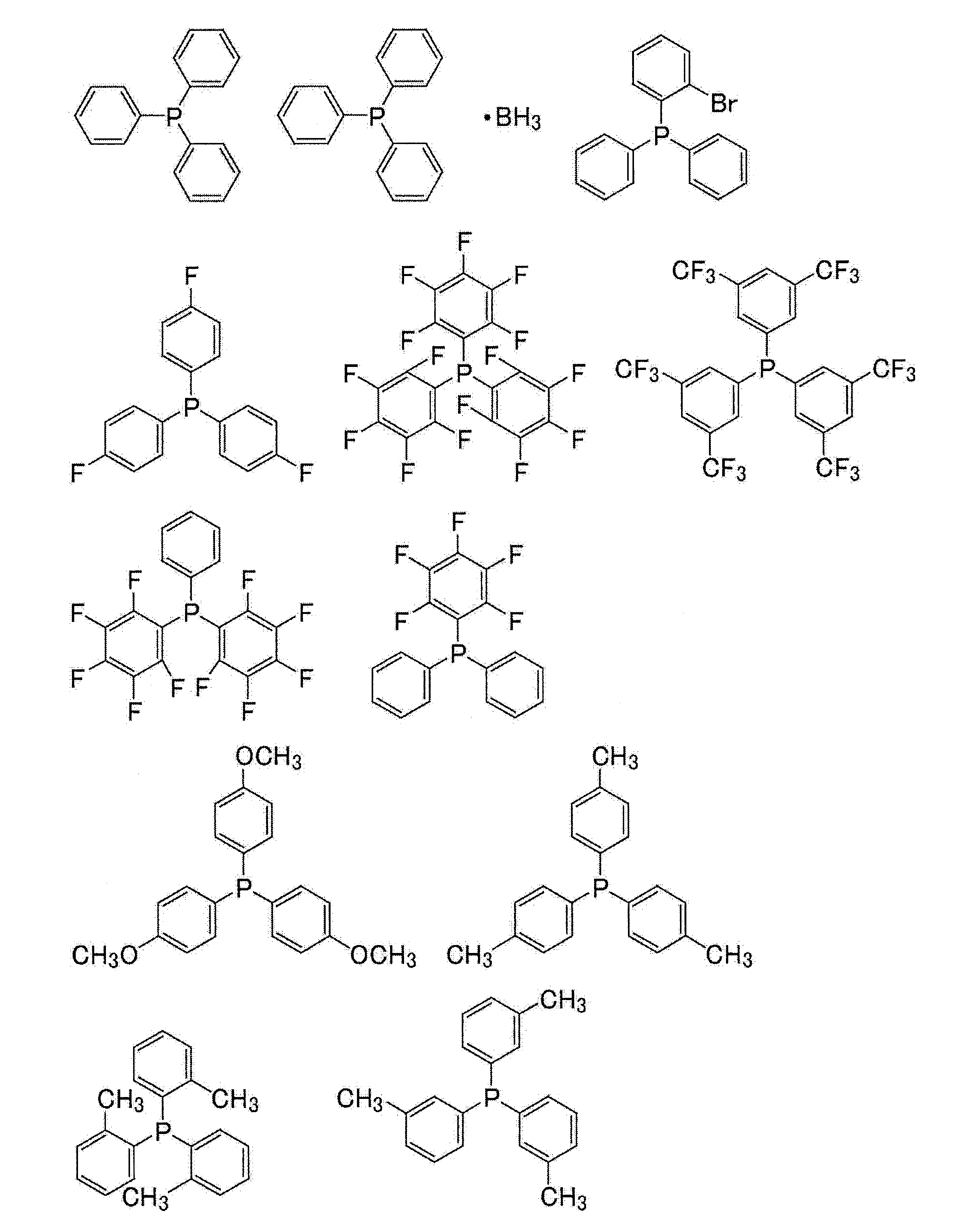


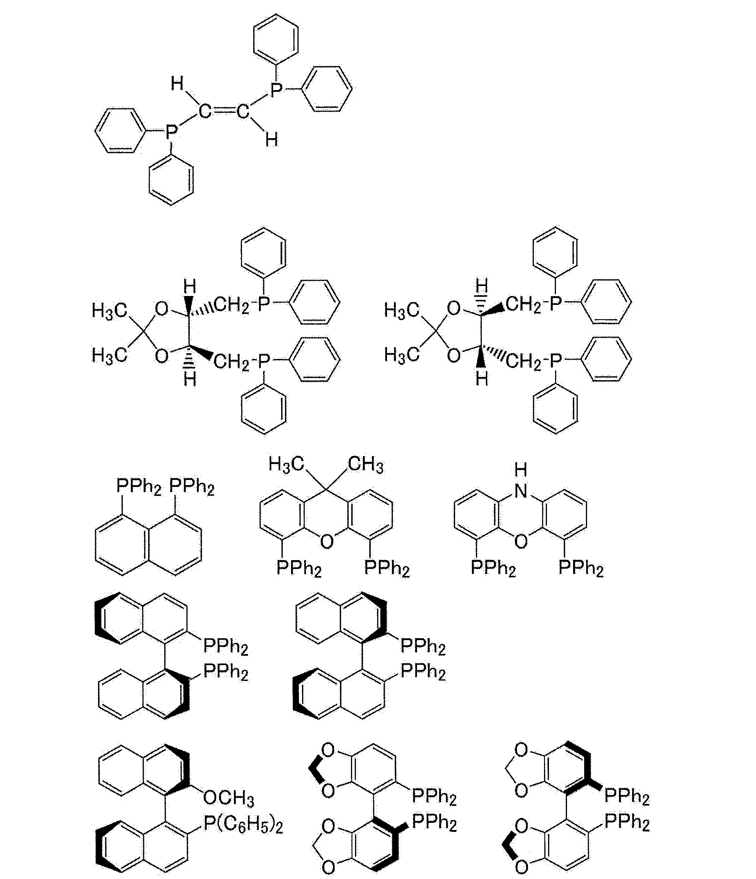

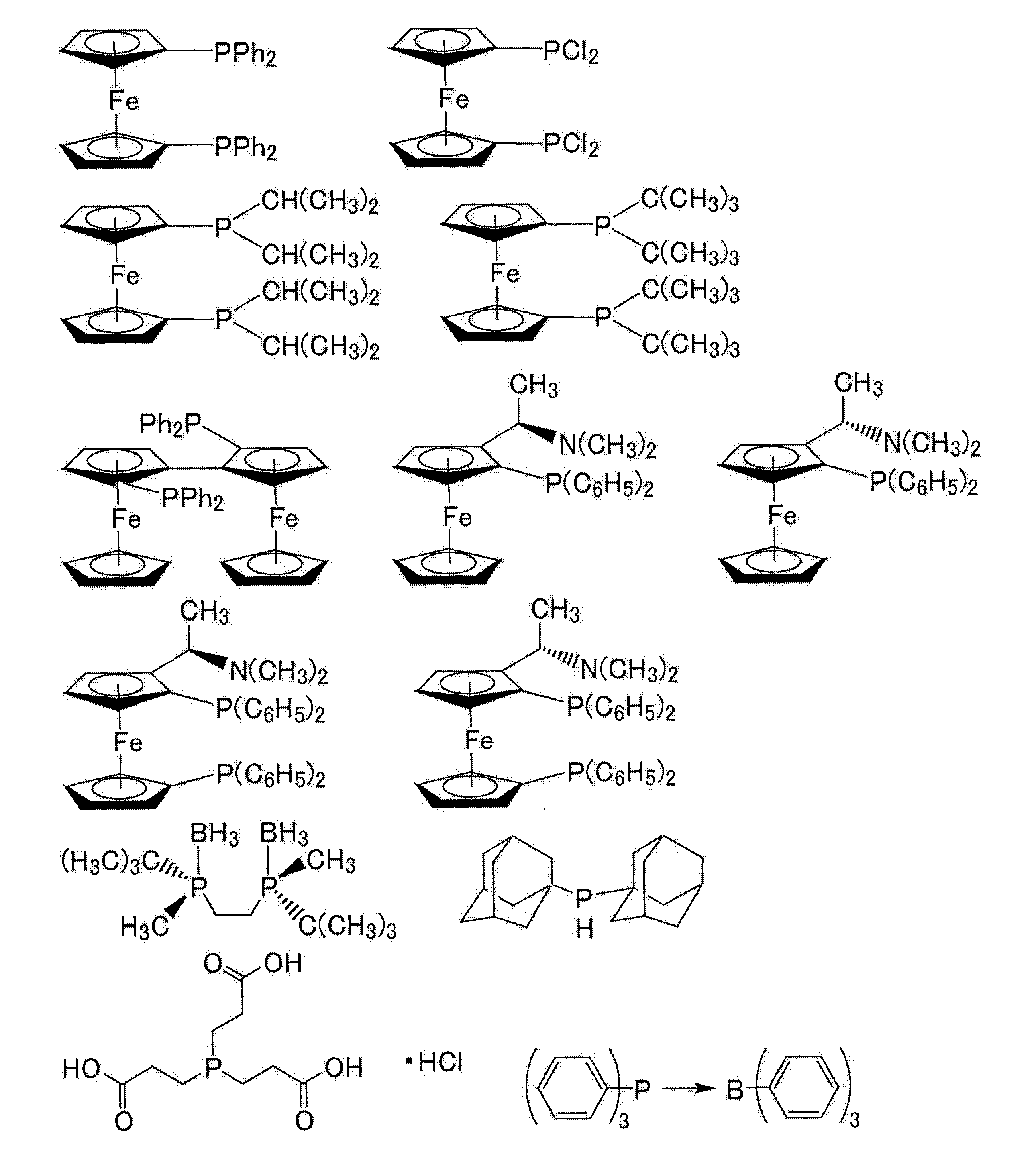
上記ホスフィン化合物としては、なかでも、次の化合物のいずれかが好ましい。上記ホスフィン化合物として、1種または2種以上を使用することができる。
As the phosphine compound, any of the following compounds is preferable. As the phosphine compound, one kind or two or more kinds can be used.

上記ホスホニウム塩としては、第4級ホスホニウム塩が好ましく、たとえば、テトラブチルホスホニウムクロリド、ベンジルトリフェニルホスホニウムクロリド、ベンジルトリメチルホスホニウムクロリド、ベンジルトリブチルホスホニウムクロリド、トリブチルアリルホスホニウムクロリド、トリブチル-2-メトキシプロピルホスホニウムクロリド、ベンジルフェニル(ジメチルアミノ)ホスホニウムクロリド、トリブチル(シアノメチル)ホスホニウムクロリドなどが挙げられる。
As the phosphonium salt, a quaternary phosphonium salt is preferable, for example, tetrabutylphosphonium chloride, benzyltriphenylphosphonium chloride, benzyltrimethylphosphonium chloride, benzyltributylphosphonium chloride, tributylallylphosphonium chloride, tributyl-2-methoxypropylphosphonium chloride. , Benzylphenyl (dimethylamino) phosphonium chloride, tributyl (cyanomethyl) phosphonium chloride and the like.
上記ホスフィンオキシド類としては、一般式:R3P(=O)(式中、3つのRは、同一または異なって、ハロゲン原子または有機基を表す)で表される化合物が好ましい。
As the phosphine oxides, compounds represented by the general formula: R 3 P (= O) (in the formula, the three Rs represent the same or different halogen atoms or organic groups) are preferable.
上記有機基としては、置換基を有していてもよい炭素数1~30の炭化水素基が挙げられる。上記炭化水素基は、直鎖、分岐鎖、単環または多環であってもよく、不飽和結合を有していてもよく、芳香族性を有していてもよく、ヘテロ原子を含んでもよい。上記置換基としては、アルコキシ基、アミノ基、シアノ基、アルデヒド基、カルボン酸基、ハロゲン原子、ホスフィン基、ホスホン基、ジフェニルホスフィノ基などが挙げられる。
Examples of the organic group include hydrocarbon groups having 1 to 30 carbon atoms which may have a substituent. The hydrocarbon group may be linear, branched, monocyclic or polycyclic, may have an unsaturated bond, may be aromatic, and may contain a heteroatom. Good. Examples of the substituent include an alkoxy group, an amino group, a cyano group, an aldehyde group, a carboxylic acid group, a halogen atom, a phosphine group, a phosphone group, a diphenylphosphino group and the like.
上記ホスフィンオキシド類としては、なかでも、次の化合物が好ましい。
Among the above phosphine oxides, the following compounds are preferable.

フッ素ゴム組成物におけるリン化合物の含有量としては、フッ素ゴム層とポリマー層とがより強固に接着することから、フッ素ゴム100質量部に対して、好ましくは0.01~20質量部であり、より好ましくは0.05~10質量部であり、さらに好ましくは0.1~5質量部であり、特に好ましくは0.2~3質量部であり、最も好ましくは0.2~1質量部である。
The content of the phosphorus compound in the fluororubber composition is preferably 0.01 to 20 parts by mass with respect to 100 parts by mass of the fluororubber because the fluororubber layer and the polymer layer adhere more firmly. It is more preferably 0.05 to 10 parts by mass, further preferably 0.1 to 5 parts by mass, particularly preferably 0.2 to 3 parts by mass, and most preferably 0.2 to 1 part by mass. is there.
〔シリカ〕
フッ素ゴム組成物は、シリカを含有してもよい。フッ素ゴム組成物がシリカを含有することによって、フッ素ゴム層とポリマー層とが一層強固に接着する。シリカとしては、塩基性シリカ、酸性シリカを用いることができ、接着性の観点から、塩基性シリカを用いる方が好ましい。塩基性シリカとしては、カープレックス1120(DSLジャパン社製)、Sidistar R300(エルケム社製)、Silene732D(PPG Industries社製)、Inhibisil75(PPG Industries社製)などが挙げられる。また、フッ素ゴム層とポリマー層が一層強固に接着することから、平均粒径が大きなシリカを用いることが好ましい。平均粒径が大きなシリカとしては、Sidistar R300(エルケム社製)、Sidistar T120U(エルケム社製)、アドマファインシリーズ(アドマテックス社製)、エクセリカシリーズ(トクヤマ社製)などが挙げられる。 〔silica〕
The fluororubber composition may contain silica. When the fluororubber composition contains silica, the fluororubber layer and the polymer layer are more firmly adhered to each other. As the silica, basic silica and acidic silica can be used, and it is preferable to use basic silica from the viewpoint of adhesiveness. Examples of the basic silica include Carplex 1120 (manufactured by DSL Japan), Sidestar R300 (manufactured by Elchem), Sirene732D (manufactured by PPG Industries), and Inhibisil75 (manufactured by PPG Industries). Further, since the fluororubber layer and the polymer layer are more firmly adhered to each other, it is preferable to use silica having a large average particle size. Examples of silica having a large average particle size include Sidestar R300 (manufactured by Elchem), Sidestar T120U (manufactured by Elchem), Admafine series (manufactured by Admatex), and Celica series (manufactured by Tokuyama).
フッ素ゴム組成物におけるシリカの含有量としては、フッ素ゴム層とポリマー層とがより強固に接着することから、フッ素ゴム100質量部に対して、好ましくは5~100質量部であり、より好ましくは10~70質量部であり、さらに好ましくは15~50質量部であり、最も好ましくは15~30質量部である。
The content of silica in the fluororubber composition is preferably 5 to 100 parts by mass, more preferably 5 to 100 parts by mass, with respect to 100 parts by mass of the fluororubber because the fluororubber layer and the polymer layer adhere more firmly. It is 10 to 70 parts by mass, more preferably 15 to 50 parts by mass, and most preferably 15 to 30 parts by mass.
〔その他の成分〕
フッ素ゴム組成物は、フッ素ゴム層とポリマー層とがより強固に接着することから、さらに、架橋剤を含むことも好ましい。架橋剤としては、パーオキサイド架橋剤などを目的に応じて選択することができる。上記フッ素ゴム組成物は、パーオキサイド架橋剤を含むことが好ましい。 [Other ingredients]
It is also preferable that the fluororubber composition further contains a cross-linking agent because the fluororubber layer and the polymer layer are more firmly adhered to each other. As the cross-linking agent, a peroxide cross-linking agent or the like can be selected according to the purpose. The fluororubber composition preferably contains a peroxide cross-linking agent.
パーオキサイド架橋剤としては特に限定されず、たとえば、有機過酸化物を挙げることができる。上記有機過酸化物としては、熱や酸化還元系の存在下で容易にパーオキシラジカルを発生するものが好ましく、たとえば1,1-ビス(t-ブチルパーオキシ)-3,5,5-トリメチルシクロヘキサン、2,5-ジメチルヘキサン-2,5-ジヒドロキシパーオキシド、ジ-t-ブチルパーオキシド、t-ブチルクミルパーオキシド、ジクミルパーオキシド、α,α’-ビス(t-ブチルパーオキシ)-p-ジイソプロピルベンゼン、2,5-ジメチル-2,5-ジ(t-ブチルパーオキシ)ヘキサン、2,5-ジメチル-2,5-ジ(t-ブチルパーオキシ)ヘキシン-3、ベンゾイルパーオキシド、t-ブチルパーオキシベンゼン、2,5-ジメチル-2,5-ジ(ベンゾイルパーオキシ)ヘキサン、t-ブチルパーオキシマレイン酸、t-ブチルパーオキシイソプロピルカーボネートなどを例示することができる。なかでも、ジアルキル化合物がより好ましい。
The peroxide cross-linking agent is not particularly limited, and examples thereof include organic peroxides. As the organic peroxide, those that easily generate peroxy radicals in the presence of heat or an oxidation-reduction system are preferable, and for example, 1,1-bis (t-butylperoxy) -3,5,5-trimethyl Cyclohexane, 2,5-dimethylhexane-2,5-dihydroxyperoxide, di-t-butylperoxide, t-butylcumylperoxide, dicumylperoxide, α, α'-bis (t-butylperoxy) -P-diisopropylbenzene, 2,5-dimethyl-2,5-di (t-butylperoxy) hexane, 2,5-dimethyl-2,5-di (t-butylperoxy) hexin-3, benzoylper Examples thereof include oxide, t-butylperoxybenzene, 2,5-dimethyl-2,5-di (benzoylperoxy) hexane, t-butylperoxymaleic acid, t-butylperoxyisopropyl carbonate and the like. Of these, dialkyl compounds are more preferable.
一般に、パーオキサイド架橋剤の使用量は、活性-O-O-の量、分解温度などから適宜選択される。フッ素ゴム組成物におけるパーオキサイド架橋剤の含有量としては、フッ素ゴム100質量部に対して、通常、0.1~15質量部であり、好ましくは0.3~5質量部であり、より好ましくは1~4質量部であり、さらに好ましくは1~2質量部である。
Generally, the amount of the peroxide cross-linking agent used is appropriately selected from the amount of activity-O-O-, the decomposition temperature, and the like. The content of the peroxide cross-linking agent in the fluororubber composition is usually 0.1 to 15 parts by mass, preferably 0.3 to 5 parts by mass, more preferably with respect to 100 parts by mass of the fluororubber. Is 1 to 4 parts by mass, more preferably 1 to 2 parts by mass.
架橋剤が有機過酸化物である場合、フッ素ゴム組成物は架橋助剤を含むことが好ましい。架橋助剤としては、例えば、トリアリルシアヌレート、トリメタリルイソシアヌレート、トリアリルイソシアヌレート(TAIC)、トリアクリルホルマール、トリアリルトリメリテート、N,N’-m-フェニレンビスマレイミド、ジプロパギルテレフタレート、ジアリルフタレート、テトラアリルテレフタレートアミド、トリアリルホスフェート、ビスマレイミド、フッ素化トリアリルイソシアヌレート(1,3,5-トリス(2,3,3-トリフルオロ-2-プロペニル)-1,3,5-トリアジン-2,4,6-トリオン)、トリス(ジアリルアミン)-S-トリアジン、亜リン酸トリアリル、N,N-ジアリルアクリルアミド、1,6-ジビニルドデカフルオロヘキサン、ヘキサアリルホスホルアミド、N,N,N’,N’-テトラアリルフタルアミド、N,N,N’,N’-テトラアリルマロンアミド、トリビニルイソシアヌレート、2,4,6-トリビニルメチルトリシロキサン、トリ(5-ノルボルネン-2-メチレン)シアヌレート、トリアリルホスファイトなどが挙げられる。これらの中でも、架橋性および架橋物の物性が優れる点から、トリアリルイソシアヌレート(TAIC)が好ましい。
When the cross-linking agent is an organic peroxide, the fluororubber composition preferably contains a cross-linking aid. Examples of the cross-linking aid include triallyl cyanurate, trimetalyl isocyanurate, triallyl isocyanurate (TAIC), triallylic formal, triallyl trimellitate, N, N'-m-phenylene bismaleimide, and dipropagil. Telephthalate, diallyl phthalate, tetraallyl terephthalate amide, triallyl phosphate, bismaleimide, fluorinated triallyl isocyanurate (1,3,5-tris (2,3,3-trifluoro-2-propenyl) -1,3, 5-Triazine-2,4,6-trione), Tris (diallylamine) -S-triazine, Triallyl phosphite, N, N-diallylacrylamide, 1,6-divinyldodecafluorohexane, Hexaallyl phosphoramide, N , N, N', N'-tetraallyl phthalamide, N, N, N', N'-tetraallyl malonamide, trivinyl isocyanurate, 2,4,6-trivinylmethyltrisiloxane, tri (5- Norbornen-2-methylene) cyanurate, triallyl phosphite and the like can be mentioned. Among these, triallyl isocyanurate (TAIC) is preferable from the viewpoint of excellent crosslinkability and physical properties of the crosslinked product.
フッ素ゴム組成物における架橋助剤の含有量としては、フッ素ゴム100質量部に対して、好ましくは0.2~10質量部であり、より好ましくは0.5~9質量部であり、さらに好ましくは2~8質量部であり、最も好ましくは3~7質量部である。
The content of the cross-linking aid in the fluororubber composition is preferably 0.2 to 10 parts by mass, more preferably 0.5 to 9 parts by mass, still more preferably, with respect to 100 parts by mass of the fluororubber. Is 2 to 8 parts by mass, most preferably 3 to 7 parts by mass.
フッ素ゴム組成物は、受酸剤として、またはフッ素ゴム層とポリマー層との接着性を向上させるための配合剤として、金属酸化物、金属水酸化物、アルカリ金属の弱酸塩、および、アルカリ土類金属の弱酸塩からなる群より選択される少なくとも1種の化合物を含有してもよい。
The fluororubber composition is used as an acid receiving agent or as a compounding agent for improving the adhesiveness between the fluororubber layer and the polymer layer, as a metal oxide, a metal hydroxide, a weak acid salt of an alkali metal, and an alkaline soil. It may contain at least one compound selected from the group consisting of weak acid salts of similar metals.
上記金属酸化物、金属水酸化物、アルカリ金属の弱酸塩およびアルカリ土類金属の弱酸塩としては、周期表第(II)族金属の酸化物、水酸化物、炭酸塩、カルボン酸塩、ケイ酸塩、ホウ酸塩、亜リン酸塩、周期表第(IV)族金属の酸化物、塩基性炭酸塩、塩基性カルボン酸塩、塩基性亜リン酸塩、塩基性亜硫酸塩などが挙げられる。
Examples of the metal oxides, metal hydroxides, alkali metal weak salts and alkaline earth metal weak acid salts include oxides, hydroxides, carbonates, carboxylates and silicates of Group (II) metal of the periodic table. Examples thereof include acid salts, borates, phosphites, oxides of Group (IV) metal of the periodic table, basic carbonates, basic carboxylic acid salts, basic sulphates, and basic sulfites. ..
金属酸化物、金属水酸化物、アルカリ金属の弱酸塩およびアルカリ土類金属の弱酸塩の具体的な例としては、酸化マグネシウム、酸化亜鉛、水酸化マグネシウム、水酸化バリウム、炭酸マグネシウム、炭酸バリウム、酸化カルシウム(生石灰)、水酸化カルシウム(消石灰)、炭酸カルシウム、ケイ酸カルシウム、ステアリン酸カルシウム、ステアリン酸亜鉛、フタル酸カルシウム、亜リン酸カルシウム、酸化錫、塩基性亜リン酸錫などをあげることができる。
Specific examples of metal oxides, metal hydroxides, alkali metal weak salts and alkaline earth metal weak salts include magnesium oxide, zinc oxide, magnesium hydroxide, barium hydroxide, magnesium carbonate, barium carbonate, etc. Examples thereof include calcium oxide (quick lime), calcium hydroxide (slaked lime), calcium carbonate, calcium silicate, calcium stearate, zinc stearate, calcium phthalate, calcium phosphite, tin oxide, and basic tin phosphite.
有機過酸化物を架橋剤として使用する場合には、上記金属酸化物、金属水酸化物、アルカリ金属の弱酸塩、アルカリ土類金属の弱酸塩の含有量は、好ましくは5質量部以下であり、より好ましくは3質量部以下であり、耐酸性の観点からは、含まないことが更に好ましい。
When an organic peroxide is used as a cross-linking agent, the content of the metal oxide, the metal hydroxide, the weak acid salt of the alkali metal, and the weak acid salt of the alkaline earth metal is preferably 5 parts by mass or less. , More preferably 3 parts by mass or less, and further preferably not contained from the viewpoint of acid resistance.
上記フッ素ゴム組成物は、必要に応じてフッ素ゴム組成物中に配合される通常の添加物、たとえば、充填剤、加工助剤、可塑剤、着色剤、安定剤、接着助剤、受酸剤、離型剤、導電性付与剤、熱伝導性付与剤、表面非粘着剤、柔軟性付与剤、耐熱性改善剤、難燃剤などの各種添加剤を配合することができ、上述のものとは異なる常用の架橋剤や架橋促進剤を1種またはそれ以上含有してもよい。
The fluororubber composition is a usual additive to be blended in the fluororubber composition as needed, for example, a filler, a processing aid, a plasticizer, a colorant, a stabilizer, an adhesive aid, and an acid receiving agent. , Mold release agent, conductivity imparting agent, thermal conductivity imparting agent, surface non-adhesive agent, flexibility imparting agent, heat resistance improving agent, flame retardant, and various other additives can be blended. It may contain one or more different commonly used cross-linking agents and cross-linking accelerators.
上記充填剤としては、カーボンブラックが挙げられる。カーボンブラックの含有量は、フッ素ゴム100質量部に対して、好ましくは0~100質量部であり、より好ましくは2~60質量部であり、さらに好ましくは5~40質量部であり、特に好ましくは10~30質量部である。カーボンブラックを使用することで、機械物性、耐熱性などの向上という利点がある。
Examples of the filler include carbon black. The content of carbon black is preferably 0 to 100 parts by mass, more preferably 2 to 60 parts by mass, still more preferably 5 to 40 parts by mass, and particularly preferably 5 to 40 parts by mass with respect to 100 parts by mass of the fluororubber. Is 10 to 30 parts by mass. The use of carbon black has the advantage of improving mechanical properties and heat resistance.
フッ素ゴム組成物は、各成分を、一般に使用されているゴム混練り装置を用いて混練りすることにより得ることができる。上記ゴム混練り装置としては、ロール、ニーダー、バンバリーミキサー、インターナルミキサー、二軸押し出し機などを用いることができる。
The fluororubber composition can be obtained by kneading each component using a commonly used rubber kneading device. As the rubber kneading device, a roll, a kneader, a Banbury mixer, an internal mixer, a twin-screw extruder and the like can be used.
(B)ポリマー層
ポリマー層とは、フッ素ゴム層とは異なる層であって、ポリマー(ただし、フッ素ゴムを除く)から形成される層である。 (B) Polymer layer The polymer layer is a layer different from the fluororubber layer and is formed from a polymer (excluding fluororubber).
ポリマー層とは、フッ素ゴム層とは異なる層であって、ポリマー(ただし、フッ素ゴムを除く)から形成される層である。 (B) Polymer layer The polymer layer is a layer different from the fluororubber layer and is formed from a polymer (excluding fluororubber).
ポリマー層を形成するポリマーとしては、樹脂であっても、ゴム(ただし、フッ素ゴムを除く)であってもよいが、樹脂であることが好ましい。
The polymer forming the polymer layer may be resin or rubber (excluding fluororubber), but resin is preferable.
ゴムとしては、たとえば、アクリロニトリル-ブタジエンゴム(NBR)またはその水素化物(HNBR)、スチレン-ブタジエンゴム(SBR)、クロロプレンゴム(CR)、ブタジエンゴム(BR)、天然ゴム(NR)、イソプレンゴム(IR)等などのジエン系ゴム、エチレン-プロピレン-ターモノマー共重合体ゴム、シリコーンゴム、ブチルゴム、エピクロルヒドリンゴム、アクリル系ゴム、塩素化ポリエチレン(CPE)、アクリロニトリル-ブタジエンゴムと塩化ビニルのポリブレンド(PVC-NBR)、エチレンプロピレンジエンゴム(EPDM)、クロロスルホン化ポリエチレン(CSM)などがあげられる。
Examples of the rubber include acrylonitrile-butadiene rubber (NBR) or a hydride thereof (HNBR), styrene-butadiene rubber (SBR), chloroprene rubber (CR), butadiene rubber (BR), natural rubber (NR), and isoprene rubber ( Diene rubber such as IR), ethylene-propylene-ter monomer copolymer rubber, silicone rubber, butyl rubber, epichlorohydrin rubber, acrylic rubber, chlorinated polyethylene (CPE), acrylonitrile-butadiene rubber and vinyl chloride polyblend ( PVC-NBR), ethylene propylene diene rubber (EPDM), chlorosulfonated polyethylene (CSM) and the like.
樹脂としては、たとえば、フッ素樹脂、ポリアミド系樹脂、ポリオレフィン系樹脂、塩化ビニル系樹脂、ポリウレタン樹脂、ポリエステル樹脂、ポリアラミド樹脂、ポリイミド樹脂、ポリアミドイミド樹脂、ポリフェニレンオキサイド樹脂、ポリアセタール樹脂、ポリカーボネート樹脂、アクリル系樹脂、スチレン系樹脂、アクリロニトリル/ブタジエン/スチレン樹脂(ABS)、セルロース系樹脂、ポリエーテルエーテルケトン樹脂(PEEK)、ポリスルホン樹脂、ポリエーテルスルホン樹脂(PES)、ポリエーテルイミド樹脂、エチレン/ビニルアルコール共重合体からなる樹脂、ポリフェニレンスルフィド樹脂、ポリブチレンナフタレート樹脂、ポリブチレンテレフタレート樹脂、ポリフタルアミド(PPA)などがあげられる。
Examples of the resin include fluororesins, polyamide resins, polyolefin resins, vinyl chloride resins, polyurethane resins, polyester resins, polyaramid resins, polyimide resins, polyamideimide resins, polyphenylene oxide resins, polyacetal resins, polycarbonate resins, and acrylic resins. Resin, styrene resin, acrylonitrile / butadiene / styrene resin (ABS), cellulose resin, polyether ether ketone resin (PEEK), polysulfone resin, polyethersulfone resin (PES), polyetherimide resin, ethylene / vinyl alcohol Examples thereof include a resin composed of a polymer, a polyphenylene sulfide resin, a polybutylene naphthalate resin, a polybutylene terephthalate resin, and a polyphthalamide (PPA).
ポリマー層を形成するポリマーとしては、なかでも、耐薬品性、燃料低透過性などに優れることから、フッ素樹脂が好ましい。
As the polymer forming the polymer layer, fluororesin is preferable because it is excellent in chemical resistance, low fuel permeability, and the like.
フッ素樹脂としては、低い燃料透過係数を有するものが好ましい。フッ素樹脂の燃料透過係数としては、好ましくは2.0g・mm/m2/day以下であり、より好ましくは1.5g・mm/m2/day以下であり、さらに好ましくは0.8g・mm/m2/day以下であり、特に好ましくは0.55g・mm/m2/day以下であり、最も好ましくは0.5g・mm/m2/day以下である。ポリマー層が上記の範囲内の燃料透過係数を有するフッ素樹脂を含有することによって、ポリマー層が優れた燃料低透過性を示し、積層体を燃料用ホースなどとして好適に使用することができる。
The fluororesin preferably has a low fuel permeability coefficient. The fuel permeation coefficient of the fluororesin is preferably 2.0 g · mm / m 2 / day or less, more preferably 1.5 g · mm / m 2 / day or less, and even more preferably 0.8 g · mm. It is / m 2 / day or less, particularly preferably 0.55 g · mm / m 2 / day or less, and most preferably 0.5 g · mm / m 2 / day or less. When the polymer layer contains a fluororesin having a fuel permeability coefficient within the above range, the polymer layer exhibits excellent fuel low permeability, and the laminate can be suitably used as a fuel hose or the like.
燃料透過係数は、イソオクタン、トルエンおよびエタノールを45:45:10の容積比で混合したイソオクタン/トルエン/エタノール混合溶媒18mLを投入した内径40mmφ、高さ20mmのSUS316製の燃料透過係数測定用カップに測定対象樹脂から下記方法により作製したフッ素樹脂シート(直径45mm、厚み120μm)を組み入れ、60℃において測定した質量変化から算出される値である。
(フッ素樹脂シートの作製方法)
樹脂ペレットを、それぞれ、直径120mmの金型に入れ、300℃に加熱したプレス機にセットし、約2.9MPaの圧力で溶融プレスして、厚さ0.12mmのフッ素樹脂シートを得、そのシートを直径45mm、厚み120μmに加工する。 The fuel permeation coefficient was measured in a SUS316 fuel permeation coefficient measuring cup having an inner diameter of 40 mmφ and a height of 20 mm containing 18 mL of an isooctane / toluene / ethanol mixed solvent in which isooctane, toluene and ethanol were mixed at a volume ratio of 45:45:10. It is a value calculated from the mass change measured at 60 ° C. by incorporating a fluororesin sheet (diameter 45 mm, thickness 120 μm) prepared from the measurement target resin by the following method.
(Method of manufacturing fluororesin sheet)
Each resin pellet was placed in a mold having a diameter of 120 mm, set in a press machine heated to 300 ° C., and melt-pressed at a pressure of about 2.9 MPa to obtain a fluororesin sheet having a thickness of 0.12 mm. The sheet is processed to a diameter of 45 mm and a thickness of 120 μm.
フッ素樹脂としては、優れた燃料低透過性を有する積層体が得られることから、ポリクロロトリフルオロエチレン(PCTFE)、CTFE系共重合体、および、TFE/HFP/VdF共重合体からなる群より選択される少なくとも1種が好ましく、ポリクロロトリフルオロエチレン(PCTFE)およびCTFE系共重合体からなる群より選択される少なくとも1種がより好ましく、燃料低透過性および柔軟性の観点から、CTFE系共重合体がさらに好ましい。
As the fluororesin, a laminate having excellent low fuel permeability can be obtained. Therefore, from the group consisting of polychlorotrifluoroethylene (PCTFE), CTFE-based copolymers, and TFE / HFP / VdF copolymers. At least one selected is preferable, and at least one selected from the group consisting of polychlorotrifluoroethylene (PCTFE) and CTFE-based copolymers is more preferable, and CTFE-based from the viewpoint of low fuel permeability and flexibility. Copolymers are more preferred.
TFE/HFP/VdF共重合体は、VdF含有率が少ないと燃料低透過性が優れることから、TFE、HFPおよびVdFの共重合割合(モル%比)がTFE/HFP/VdF=75~95/0.1~10/0.1~19であることが好ましく、77~95/1~8/1~17(モル比)であることがより好ましく、77~95/2~8/2~15.5(モル比)であることがさらに好ましく、79~90/5~8/5~15(モル比)であることが最も好ましい。また、TFE/HFP/VdF共重合体はその他のモノマーを0~20モル%含んでいてもよい。他のモノマーとしては、パーフルオロ(メチルビニルエーテル)、パーフルオロ(エチルビニルエーテル)、パーフルオロ(プロピルビニルエーテル)、クロロトリフルオロエチレン、2-クロロペンタフルオロプロペン、過フッ素化されたビニルエーテル(たとえばCF3OCF2CF2CF2OCF=CF2などのペルフルオロアルコキシビニルエーテル)などのフッ素含有モノマー、ペルフルオロアルキルビニルエーテル、ペルフルオロ-1,3-ブタジエン、トリフルオロエチレン、ヘキサフルオロイソブテン、フッ化ビニル、エチレン、プロピレン、および、アルキルビニルエーテルからなる群より選択される少なくとも一種のモノマーなどが挙げられ、パーフルオロ(メチルビニルエーテル)、パーフルオロ(エチルビニルエーテル)、パーフルオロ(プロピルビニルエーテル)であることが好ましい。
Since the TFE / HFP / VdF copolymer is excellent in low fuel permeability when the VdF content is low, the copolymerization ratio (mol% ratio) of TFE, HFP and VdF is TFE / HFP / VdF = 75 to 95 /. It is preferably 0.1 to 10 / 0.1 to 19, more preferably 77 to 95/1 to 8/1 to 17 (molar ratio), and 77 to 95/2 to 8/2 to 15 It is more preferably .5 (molar ratio), and most preferably 79 to 90/5 to 8/5 to 15 (molar ratio). Further, the TFE / HFP / VdF copolymer may contain 0 to 20 mol% of other monomers. Other monomers include perfluoro (methyl vinyl ether), perfluoro (ethyl vinyl ether), perfluoro (propyl vinyl ether), chlorotrifluoroethylene, 2-chloropentafluoropropene, and perfluorinated vinyl ether (eg CF 3 OCF). Fluorine-containing monomers such as 2 CF 2 CF 2 OCF = perfluoroalkoxyvinyl ethers such as CF 2 ), perfluoroalkyl vinyl ethers, perfluoro-1,3-butadiene, trifluoroethylene, hexafluoroisobutene, vinyl fluoride, ethylene, propylene, and , At least one monomer selected from the group consisting of alkyl vinyl ethers, and the like, preferably perfluoro (methyl vinyl ether), perfluoro (ethyl vinyl ether), and perfluoro (propyl vinyl ether).
PCTFEは、クロロトリフルオロエチレンの単独重合体である。
PCTFE is a homopolymer of chlorotrifluoroethylene.
CTFE系共重合体としては、CTFEに由来する共重合単位(CTFE単位)と、TFE、HFP、PAVE、VdF、フッ化ビニル、ヘキサフルオロイソブテン、式:CH2=CX3(CF2)nX4(式中、X3はHまたはF、X4はH、FまたはCl、nは1~10の整数である)で示される単量体、エチレン、プロピレン、1-ブテン、2-ブテン、塩化ビニル、および、塩化ビニリデンからなる群より選択される少なくとも1種の単量体に由来する共重合単位と、を含むことが好ましい。また、CTFE系共重合体は、パーハロポリマーであることがより好ましい。
The CTFE-based copolymer includes a copolymerization unit (CTFE unit) derived from CTFE, TFE, HFP, PAVE, VdF, vinyl fluoride, hexafluoroisobutene, and formula: CH 2 = CX 3 (CF 2 ) n X. Monomer represented by 4 (in the formula, X 3 is H or F, X 4 is H, F or Cl, n is an integer of 1 to 10), ethylene, propylene, 1-butene, 2-butene, It preferably contains vinyl chloride and a copolymerization unit derived from at least one monomer selected from the group consisting of vinylidene chloride. Further, the CTFE-based copolymer is more preferably a perhalopolymer.
CTFE系共重合体としては、CTFE単位と、TFE、HFPおよびPAVEからなる群より選択される少なくとも1種の単量体に由来する共重合単位と、を含むことがより好ましく、実質的にこれらの共重合単位のみからなることが更に好ましい。また、燃料低透過性の観点から、エチレン、フッ化ビニリデン、フッ化ビニルなどのCH結合を有するモノマーを含まないことが好ましい。
The CTFE-based copolymer more preferably contains a CTFE unit and a copolymerization unit derived from at least one monomer selected from the group consisting of TFE, HFP and PAVE, and substantially these. It is more preferable that it comprises only the copolymerization unit of. Further, from the viewpoint of low fuel permeability, it is preferable not to contain a monomer having a CH bond such as ethylene, vinylidene fluoride, and vinyl fluoride.
CH結合を有するモノマーを含まないパーハロポリマーはフッ素ゴムとの接着が通常困難であるが、本開示の構成によれば、ポリマー層がパーハロポリマーを含有する場合であっても、フッ素ゴム層とポリマー層との層間の接着は強固である。
A monomer-free perhalopolymer having a CH bond is usually difficult to adhere to a fluororubber, but according to the configuration of the present disclosure, even when the polymer layer contains a perhalopolymer, the fluororubber layer The adhesion between the layer and the polymer layer is strong.
CTFE系共重合体は、全単量体単位の10~90モル%のCTFE単位を有することが好ましい。
The CTFE-based copolymer preferably has 10 to 90 mol% of CTFE units of all monomer units.
CTFE系共重合体としては、CTFE単位、TFE単位およびこれらと共重合可能な単量体(α)に由来する単量体(α)単位を含むものが特に好ましい。
As the CTFE-based copolymer, those containing a CTFE unit, a TFE unit, and a monomer (α) unit derived from a monomer (α) copolymerizable with these are particularly preferable.
「CTFE単位」および「TFE単位」は、CTFE系共重合体の分子構造上、それぞれ、CTFEに由来する部分(-CFCl-CF2-)、TFEに由来する部分(-CF2-CF2-)であり、前記「単量体(α)単位」は、同様に、CTFE系共重合体の分子構造上、単量体(α)が付加してなる部分である。
"CTFE unit" and "TFE unit", the molecular structure of the CTFE copolymer, respectively, portions derived from CTFE (-CFCl-CF 2 -) , moieties derived from TFE (-CF 2 -CF 2 - ), And the "monomer (α) unit" is similarly a portion to which the monomer (α) is added due to the molecular structure of the CTFE-based copolymer.
単量体(α)としては、CTFEおよびTFEと共重合可能な単量体であれば特に限定されず、エチレン(Et)、ビニリデンフルオライド(VdF)、CF2=CF-ORf2(式中、Rf2は、炭素数1~8のパーフルオロアルキル基)で表されるPAVE、CX5X6=CX7(CF2)nX8(式中、X5、X6およびX7は同一もしくは異なって、水素原子またはフッ素原子;X8は、水素原子、フッ素原子または塩素原子;nは、1~10の整数)で表されるビニル単量体、CF2=CF-O-Rf3(式中、Rf3は、炭素数1~5のパーフルオロアルキル基)で表されるアルキルパーフルオロビニルエーテル誘導体などがあげられる。
The monomer (α) is not particularly limited as long as it is a monomer copolymerizable with CTFE and TFE, and ethylene (Et), vinylidene fluoride (VdF), CF 2 = CF-ORf 2 (in the formula). , Rf 2 is a perfluoroalkyl group having 1 to 8 carbon atoms) PAVE, CX 5 X 6 = CX 7 (CF 2 ) n X 8 (In the formula, X 5 , X 6 and X 7 are the same. Or differently, a vinyl monomer represented by a hydrogen atom or a fluorine atom; X 8 is a hydrogen atom, a fluorine atom or a chlorine atom; n is an integer of 1 to 10), CF 2 = CF-O-Rf 3 (In the formula, Rf 3 is a perfluoroalkyl group having 1 to 5 carbon atoms), and examples thereof include an alkyl perfluorovinyl ether derivative.
上記アルキルパーフルオロビニルエーテル誘導体としては、Rf3が炭素数1~3のパーフルオロアルキル基であるものが好ましく、CF2=CF-OCF2-CF2CF3がより好ましい。
As the alkyl perfluorovinyl ether derivative, those in which Rf 3 is a perfluoroalkyl group having 1 to 3 carbon atoms are preferable, and CF 2 = CF-OCF 2 -CF 2 CF 3 is more preferable.
単量体(α)としては、なかでも、PAVE、上記ビニル単量体、および、アルキルパーフルオロビニルエーテル誘導体からなる群より選択される少なくとも1種であることが好ましく、PAVEおよびHFPからなる群より選択される少なくとも1種であることがより好ましく、PAVEが特に好ましい。
The monomer (α) is preferably at least one selected from the group consisting of PAVE, the above-mentioned vinyl monomer, and an alkyl perfluorovinyl ether derivative, and more preferably than the group consisting of PAVE and HFP. It is more preferably at least one selected, and PAVE is particularly preferable.
CTFE系共重合体における、CTFE単位とTFE単位との比率は、CTFE単位が15~90モル%に対し、TFE単位が85~10モル%であり、より好ましくは、CTFE単位が20~90モル%であり、TFE単位が80~10モル%である。また、CTFE単位15~25モル%と、TFE単位85~75モル%とから構成されるものも好ましい。
The ratio of the CTFE unit to the TFE unit in the CTFE-based copolymer is 15 to 90 mol% for the CTFE unit and 85 to 10 mol% for the TFE unit, more preferably 20 to 90 mol% for the CTFE unit. %, And the TFE unit is 80-10 mol%. Further, those composed of 15 to 25 mol% of CTFE units and 85 to 75 mol% of TFE units are also preferable.
CTFE系共重合体は、CTFE単位とTFE単位との合計が90~99.9モル%であり、単量体(α)単位が0.1~10モル%であるものが好ましい。単量体(α)単位が0.1モル%未満であると、成形性、耐環境応力割れ性および耐燃料クラック性に劣りやすく、10モル%を超えると、燃料低透過性、耐熱性、機械特性に劣る傾向にある。
The total of CTFE units and TFE units of the CTFE-based copolymer is 90 to 99.9 mol%, and the monomer (α) unit is preferably 0.1 to 10 mol%. If the monomer (α) unit is less than 0.1 mol%, the moldability, environmental stress cracking resistance and fuel cracking resistance are likely to be inferior, and if it exceeds 10 mol%, fuel low permeability and heat resistance, It tends to be inferior in mechanical properties.
フッ素樹脂としては、燃料低透過性、接着性の観点から、PCTFE、CTFE/TFE/PAVE共重合体およびTFE/HFP/VdF共重合体からなる群より選択される少なくとも1種がより好ましく、CTFE/TFE/PAVE共重合体およびTFE/HFP/VdF共重合体からなる群より選択される少なくとも1種がさらに好ましく、CTFE/TFE/PAVE共重合体が特に好ましい。
CTFE/TFE/PAVE共重合体とは、実質的にCTFE、TFEおよびPAVEのみからなる共重合体である。 As the fluororesin, at least one selected from the group consisting of PCTFE, CTFE / TFE / PAVE copolymer and TFE / HFP / VdF copolymer is more preferable from the viewpoint of low fuel permeability and adhesiveness, and CTFE is more preferable. At least one selected from the group consisting of / TFE / PAVE copolymers and TFE / HFP / VdF copolymers is more preferable, and CTFE / TFE / PAVE copolymers are particularly preferable.
The CTFE / TFE / PAVE copolymer is a copolymer consisting substantially only of CTFE, TFE and PAVE.
CTFE/TFE/PAVE共重合体において、上記PAVEとしては、パーフルオロ(メチルビニルエーテル)(PMVE)、パーフルオロ(エチルビニルエーテル)(PEVE)、パーフルオロ(プロピルビニルエーテル)(PPVE)、パーフルオロ(ブチルビニルエーテル)などがあげられ、なかでもPMVE、PEVEおよびPPVEからなる群より選択される少なくとも1種が好ましい。
CTFE/TFE/PAVE共重合体において、PAVE単位は、全単量体単位の0.5モル%以上であることが好ましく、5モル%以下であることが好ましい。 In the CTFE / TFE / PAVE copolymer, the above-mentioned PAVE includes perfluoro (methyl vinyl ether) (PMVE), perfluoro (ethyl vinyl ether) (PEVE), perfluoro (propyl vinyl ether) (PPVE), and perfluoro (butyl vinyl ether). ), Etc., and among them, at least one selected from the group consisting of PMVE, PEVE and PPVE is preferable.
In the CTFE / TFE / PAVE copolymer, the PAVE unit is preferably 0.5 mol% or more and preferably 5 mol% or less of all the monomer units.
CTFE単位などの構成単位は、19F-NMR分析を行うことにより得られる値である。
Constituent units such as CTFE units are values obtained by performing 19 F-NMR analysis.
フッ素樹脂は、ポリマーの主鎖末端および/または側鎖に、カルボニル基、ヒドロキシル基、ヘテロ環基、およびアミノ基からなる群より選択される少なくとも1種の反応性官能基を導入したものであってもよい。
The fluororesin is obtained by introducing at least one reactive functional group selected from the group consisting of a carbonyl group, a hydroxyl group, a heterocyclic group, and an amino group into the main chain terminal and / or side chain of the polymer. You may.
本開示において、「カルボニル基」は、炭素-酸素二重結合から構成される炭素2価の基であり、-C(=O)-で表されるものに代表される。カルボニル基を含む反応性官能基としては特に限定されず、たとえば、カーボネート基、カルボン酸ハライド基(ハロゲノホルミル基)、ホルミル基、カルボキシル基、エステル結合(-C(=O)O-)、酸無水物結合(-C(=O)O-C(=O)-)、イソシアネート基、アミド基、イミド基(-C(=O)-NH-C(=O)-)、ウレタン結合(-NH-C(=O)O-)、カルバモイル基(NH2-C(=O)-)、カルバモイルオキシ基(NH2-C(=O)O-)、ウレイド基(NH2-C(=O)-NH-)、オキサモイル基(NH2-C(=O)-C(=O)-)など、化学構造上の一部としてカルボニル基を含むものがあげられる。
In the present disclosure, the "carbonyl group" is a carbon divalent group composed of a carbon-oxygen double bond, and is represented by a group represented by -C (= O)-. The reactive functional group containing a carbonyl group is not particularly limited, and for example, a carbonate group, a carboxylic acid halide group (halogenoformyl group), a formyl group, a carboxyl group, an ester bond (-C (= O) O-), an acid. Anhydrous bond (-C (= O) OC (= O)-), isocyanate group, amide group, imide group (-C (= O) -NH-C (= O)-), urethane bond (-) NH-C (= O) O- ), a carbamoyl group (NH 2 -C (= O) -), a carbamoyloxy group (NH 2 -C (= O) O-), a ureido group (NH 2 -C (= O) -NH-), oxamoyl group (NH 2 -C (= O) -C (= O) -) , etc., it can be mentioned those containing a carbonyl group as part of the chemical structure.
アミド基、イミド基、ウレタン結合、カルバモイル基、カルバモイルオキシ基、ウレイド基、オキサモイル基などにおいては、その窒素原子に結合する水素原子は、たとえばアルキル基などの炭化水素基で置換されていてもよい。
In the amide group, imide group, urethane bond, carbamoyl group, carbamoyloxy group, ureido group, oxamoyl group and the like, the hydrogen atom bonded to the nitrogen atom may be substituted with a hydrocarbon group such as an alkyl group. ..
反応性官能基は、導入が容易である点、フッ素樹脂が適度な耐熱性と比較的低温での良好な接着性とを有する点から、アミド基、カルバモイル基、ヒドロキシル基、カルボキシル基、カーボネート基、カルボン酸ハライド基、酸無水物結合が好ましく、さらにはアミド基、カルバモイル基、ヒドロキシル基、カーボネート基、カルボン酸ハライド基、酸無水物結合が好ましい。
Reactive functional groups are amide groups, carbamoyl groups, hydroxyl groups, carboxyl groups, and carbonate groups because they are easy to introduce and the fluororesin has appropriate heat resistance and good adhesion at relatively low temperatures. , Carboxylic acid halide group, acid anhydride bond is preferable, and further, amide group, carbamoyl group, hydroxyl group, carbonate group, carboxylic acid halide group and acid anhydride bond are preferable.
フッ素樹脂は、懸濁重合、溶液重合、乳化重合、塊状重合など、従来公知の重合方法により得ることができる。前記重合において、温度、圧力などの各条件、重合開始剤やその他の添加剤は、フッ素樹脂の組成や量に応じて適宜設定することができる。
Fluororesin can be obtained by conventionally known polymerization methods such as suspension polymerization, solution polymerization, emulsion polymerization and bulk polymerization. In the polymerization, each condition such as temperature and pressure, the polymerization initiator and other additives can be appropriately set according to the composition and amount of the fluororesin.
フッ素樹脂の融点は特に限定されないが、好ましくは160~270℃である。フッ素樹脂の融点は、DSC装置(セイコー社製)を用い、10℃/分の速度で昇温したときの融解熱曲線における極大値に対応する温度として求める。
The melting point of the fluororesin is not particularly limited, but is preferably 160 to 270 ° C. The melting point of the fluororesin is determined as a temperature corresponding to the maximum value in the heat of fusion curve when the temperature is raised at a rate of 10 ° C./min using a DSC device (manufactured by Seiko Co., Ltd.).
また、フッ素樹脂の分子量は、得られる積層体が良好な機械特性や燃料低透過性などを発現できるような範囲であることが好ましい。たとえば、メルトフローレート(MFR)を分子量の指標とする場合、フッ素樹脂一般の成形温度範囲である約230~350℃の範囲の任意の温度におけるMFRは、好ましくは0.5~100g/10分であり、より好ましくは1~50g/10分であり、更に好ましくは、2~35g/10分である。たとえば、フッ素樹脂が、PCTFE、CTFE系共重合体またはTFE/HFP/VdF共重合体である場合には、297℃でMFRを測定する。
Further, the molecular weight of the fluororesin is preferably in a range in which the obtained laminate can exhibit good mechanical properties, low fuel permeability, and the like. For example, when melt flow rate (MFR) is used as an index of molecular weight, the MFR at an arbitrary temperature in the range of about 230 to 350 ° C., which is the general molding temperature range of fluororesin, is preferably 0.5 to 100 g / 10 minutes. It is more preferably 1 to 50 g / 10 minutes, and even more preferably 2 to 35 g / 10 minutes. For example, when the fluororesin is a PCTFE, CTFE-based copolymer or TFE / HFP / VdF copolymer, the MFR is measured at 297 ° C.
MFRは、メルトインデクサー(東洋精機製作所社製)を用い、たとえば、297℃、5kg荷重下で直径2mm、長さ8mmのノズルから単位時間(10分間)に流出するポリマーの重量(g)を測定することにより特定できる。
The MFR uses a melt indexer (manufactured by Toyo Seiki Seisakusho Co., Ltd.) to determine the weight (g) of the polymer flowing out from a nozzle having a diameter of 2 mm and a length of 8 mm in a unit time (10 minutes) at 297 ° C. under a load of 5 kg. It can be identified by measuring.
ポリマー層は、これらのフッ素樹脂を1種含有するものであってもよいし、2種以上含有するものであってもよい。
The polymer layer may contain one kind of these fluororesins, or may contain two or more kinds of these fluororesins.
なお、フッ素樹脂がパーハロポリマーである場合、耐薬品性および燃料低透過性がより優れたものとなる。パーハロポリマーとは、重合体の主鎖を構成する炭素原子の全部にハロゲン原子が結合している重合体である。
When the fluororesin is a perhalopolymer, the chemical resistance and low fuel permeability are more excellent. A perhalopolymer is a polymer in which halogen atoms are bonded to all of the carbon atoms constituting the main chain of the polymer.
ポリマー層は、さらに、目的や用途に応じてその性能を損なわない範囲で、無機質粉末、ガラス繊維、炭素粉末、炭素繊維、金属酸化物などの種々の充填剤を配合したものであってもよい。
The polymer layer may further contain various fillers such as inorganic powder, glass fiber, carbon powder, carbon fiber, and metal oxide, depending on the purpose and application, as long as the performance is not impaired. ..
たとえば、燃料透過性をさらに低減させるために、モンモリロナイト、バイデライト、サポナイト、ノントロナイト、ヘクトライト、ソーコナイト、スチブンサイトなどのスメクタイト系の層状粘度鉱物や、雲母などの高アスペクト比を有する微小層状鉱物を添加してもよい。
For example, in order to further reduce fuel permeability, smectite-based layered viscosity minerals such as montmorillonite, biderite, saponite, nontronite, hectorite, saponite, and stibunsite, and microlayer minerals with a high aspect ratio such as mica are used. It may be added.
また、導電性を付与するために、導電性フィラーを添加してもよい。導電性フィラーとしては特に限定されず、たとえば金属、炭素などの導電性単体粉末または導電性単体繊維;酸化亜鉛などの導電性化合物の粉末;表面導電化処理粉末などがあげられる。導電性フィラーを配合する場合、溶融混練して予めペレットを作製することが好ましい。
Further, a conductive filler may be added in order to impart conductivity. The conductive filler is not particularly limited, and examples thereof include a conductive single powder such as metal and carbon or a conductive single fiber; a powder of a conductive compound such as zinc oxide; and a surface conductive treated powder. When the conductive filler is blended, it is preferable to prepare pellets in advance by melt-kneading.
導電性単体粉末または導電性単体繊維としては特に限定されず、たとえば銅、ニッケルなどの金属粉末;鉄、ステンレススチールなどの金属繊維;カーボンブラック、炭素繊維、特開平3-174018号公報などに記載の炭素フィブリルなどがあげられる。
The conductive single powder or the conductive single fiber is not particularly limited, and is described in, for example, a metal powder such as copper and nickel; a metal fiber such as iron and stainless steel; carbon black, carbon fiber, JP-A-3-174018 and the like. Carbon fibrils and the like.
表面導電化処理粉末は、ガラスビーズ、酸化チタンなどの非導電性粉末の表面に導電化処理を施して得られる粉末である。
The surface conductive treatment powder is a powder obtained by subjecting the surface of a non-conductive powder such as glass beads or titanium oxide to a conductive treatment.
表面導電化処理の方法としては特に限定されず、たとえば金属スパッタリング、無電解メッキなどがあげられる。
The method of surface conductivity treatment is not particularly limited, and examples thereof include metal sputtering and electroless plating.
導電性フィラーのなかでもカーボンブラックは、経済性や静電荷蓄積防止の観点で有利であるので好適に用いられる。
Among the conductive fillers, carbon black is preferably used because it is advantageous from the viewpoint of economy and prevention of static charge accumulation.
導電性フィラーを配合してなるフッ素樹脂組成物の体積抵抗率は、1×100~1×10⁹Ω・cmであることが好ましい。より好ましい下限は、1×10²Ω・cmであり、より好ましい上限は、1×10⁸Ω・cmである。
The volume resistivity of the fluororesin composition was formed by blending a conductive filler is preferably 1 × 10 0 ~ 1 × 10 9 Ω · cm. A more preferable lower limit is 1 × 10 2 Ω · cm, and a more preferable upper limit is 1 × 10 8 Ω · cm.
また、充填剤以外に、熱安定化剤、補強剤、紫外線吸収剤、顔料、その他任意の添加剤を配合してもよい。
In addition to the filler, a heat stabilizer, a reinforcing agent, an ultraviolet absorber, a pigment, and any other additive may be blended.
(積層体)
フッ素ゴム層の厚みは限定されないが、たとえば、100μm以上であることが好ましい。フッ素ゴム層の厚みの上限としては、たとえば、5000μmである。 (Laminated body)
The thickness of the fluororubber layer is not limited, but is preferably 100 μm or more, for example. The upper limit of the thickness of the fluororubber layer is, for example, 5000 μm.
フッ素ゴム層の厚みは限定されないが、たとえば、100μm以上であることが好ましい。フッ素ゴム層の厚みの上限としては、たとえば、5000μmである。 (Laminated body)
The thickness of the fluororubber layer is not limited, but is preferably 100 μm or more, for example. The upper limit of the thickness of the fluororubber layer is, for example, 5000 μm.
ポリマー層の厚みは限定されないが、たとえば、10μm以上であることが好ましい。ポリマー層の厚みの上限としては、たとえば、1000μmである。
The thickness of the polymer layer is not limited, but is preferably 10 μm or more, for example. The upper limit of the thickness of the polymer layer is, for example, 1000 μm.
積層体におけるフッ素ゴム層とポリマー層との接着強度としては、好ましくは7N/cm以上であり、より好ましくは11N/cm以上であり、さらに好ましくは12N/cm以上であり、特に好ましくは15N/cm以上である。接着強度が上記範囲にあると、ホースを特定の形状で架橋する際にズレが起こりにくい、衝撃が加わった際に剥がれが起こらないという利点がある。本開示の積層体は、上記構成を有することによって、接着強度を上記範囲にすることができる。
The adhesive strength between the fluororubber layer and the polymer layer in the laminate is preferably 7 N / cm or more, more preferably 11 N / cm or more, still more preferably 12 N / cm or more, and particularly preferably 15 N / cm or more. It is cm or more. When the adhesive strength is within the above range, there are advantages that the hose is less likely to be displaced when the hose is crosslinked with a specific shape, and that the hose is not peeled off when an impact is applied. By having the above-mentioned structure, the laminated body of the present disclosure can have the adhesive strength in the above-mentioned range.
接着強度は、積層体を幅10mm×長さ40mm×3セットの短冊状に切断し、試料片を作成し、この試験片について、フッ素ゴム層とポリマー層との境界面の接着強度の影響を排除して、接着面のみの接着強度を測定するために、フッ素ゴム層とポリマー層との界面を一度ゆっくりと手で引っ張ることにより2~3mm掴みしろを増やしてから、オートグラフ(島津製作所社製 AGS-J 5kN)を使用して、JIS-K-6256(加硫ゴムの接着試験方法)に記載の方法に準拠し、25℃において50mm/分の引張速度で剥離試験を行い、剥離モードを観測して測定する値である。
The adhesive strength is determined by cutting the laminate into strips of width 10 mm x length 40 mm x 3 sets to prepare a sample piece, and for this test piece, the effect of the adhesive strength on the interface between the fluororubber layer and the polymer layer. In order to eliminate and measure the adhesive strength of only the adhesive surface, the interface between the fluororubber layer and the polymer layer is slowly pulled once by hand to increase the grip margin by 2 to 3 mm, and then Autograph (Shimadzu Seisakusho Co., Ltd.) AGS-J 5kN) is used to perform a peeling test at a tensile speed of 50 mm / min at 25 ° C. in accordance with the method described in JIS-K-6256 (adhesion test method for fluoropolymer), and a peeling mode is performed. It is a value to be measured by observing.
本開示の積層体においては、フッ素ゴム層とポリマー層とが直接接着していることが好ましく、直接架橋接着していることがより好ましい。このような積層体は、未架橋のフッ素ゴム層とポリマー層とを積層した後、架橋処理することにより得られる。本開示の積層体は、架橋積層体であってよい。
In the laminate of the present disclosure, the fluororubber layer and the polymer layer are preferably directly bonded, and more preferably directly crosslinked. Such a laminate can be obtained by laminating an uncrosslinked fluororubber layer and a polymer layer and then subjecting them to crosslinking. The laminate of the present disclosure may be a crosslinked laminate.
架橋処理は、従来公知のフッ素ゴム組成物の架橋方法と条件が採用できる。たとえば、未架橋の積層体を長時間架橋する方法、未架橋の積層体を比較的短時間で前処理としての熱処理を行い(架橋も生じている)、ついで長時間かけて架橋を行う方法がある。これらのうち、未架橋の積層体を比較的短時間で前処理としての熱処理を行い、ついで長時間かけて架橋を行う方法が、前処理でフッ素ゴム層とポリマー層との接着性が容易に得られ、また、前処理で既にフッ素ゴム層が架橋しており形状が安定化しているので、その後の架橋における積層体の保持方法をさまざまに選択することができるので好適である。
For the cross-linking treatment, conventionally known cross-linking methods and conditions for fluororubber compositions can be adopted. For example, a method of cross-linking an uncrosslinked laminate for a long time, a method of heat-treating an uncrosslinked laminate as a pretreatment in a relatively short time (crosslinking has also occurred), and then a method of performing crosslinking over a long period of time is there. Of these, the method in which the uncrosslinked laminate is heat-treated as a pretreatment in a relatively short time and then crosslinked over a long period of time facilitates the adhesion between the fluororubber layer and the polymer layer in the pretreatment. Further, since the fluororubber layer has already been crosslinked in the pretreatment and the shape is stabilized, various methods for holding the laminate in the subsequent crosslinking can be selected, which is preferable.
架橋処理の条件は特に制限されるものではなく、通常の条件で行うことができるが、140~180℃で、2分~80分、スチーム、プレス、オーブン、エアーバス、赤外線、マイクロウェーブ、被鉛架橋などを用いて処理を行うことが好ましい。より好ましくは、150~170℃で、5~60分かけて行う。架橋処理を1次架橋と2次架橋に分けて行ってもよい。
The conditions of the cross-linking treatment are not particularly limited and can be carried out under normal conditions, but at 140 to 180 ° C. for 2 to 80 minutes, steam, press, oven, air bath, infrared rays, microwaves, subject. It is preferable to carry out the treatment using lead cross-linking or the like. More preferably, it is carried out at 150 to 170 ° C. for 5 to 60 minutes. The cross-linking treatment may be divided into a primary cross-linking and a secondary cross-linking.
本開示の積層体は、たとえば、フッ素ゴムと、塩基性の多官能化合物と、ポリテトラフルオロエチレンとを混合してフッ素ゴム組成物を得る工程、上記フッ素ゴム組成物を成形して得られる未架橋フッ素ゴム層と、ポリマー層とを積層する工程、積層された未架橋フッ素ゴム層とポリマー層とを架橋処理する工程、を含む積層体の製造方法により、好適に製造することができる。上記の製造方法において、架橋処理の条件は上述したものと同じである。
The laminate of the present disclosure is, for example, a step of mixing a fluororubber, a basic polyfunctional compound, and polytetrafluoroethylene to obtain a fluororubber composition, and is not obtained by molding the above-mentioned fluororubber composition. It can be preferably produced by a method for producing a laminated body, which includes a step of laminating the crosslinked fluororubber layer and the polymer layer, and a step of crosslinking the laminated uncrosslinked fluororubber layer and the polymer layer. In the above production method, the conditions of the crosslinking treatment are the same as those described above.
フッ素ゴムと、塩基性の多官能化合物と、ポリテトラフルオロエチレンとの混合は、たとえば、フッ素ゴムと、塩基性の多官能化合物と、ポリテトラフルオロエチレンとを、一般に使用されているゴム混練り装置を用いて混練りすることにより、行うことできる。
ゴム混練り装置としては、ロール、ニーダー、バンバリーミキサー、インターナルミキサー、二軸押し出し機などを用いることができる。
混合は、フッ素ゴムと、塩基性の多官能化合物と、ポリテトラフルオロエチレンとに加え、必要に応じて、架橋剤、架橋助剤、共架橋剤、架橋促進剤、充填剤などのその他添加剤とともに混合するものであってよい。
混合の温度は、たとえば、20~200℃である。また、上記混合の時間は、たとえば、2~80分である。 Mixing of fluororubber, basic polyfunctional compound, and polytetrafluoroethylene is, for example, rubber kneading of fluororubber, basic polyfunctional compound, and polytetrafluoroethylene, which are generally used. This can be done by kneading with an apparatus.
As the rubber kneading device, a roll, a kneader, a Banbury mixer, an internal mixer, a twin-screw extruder and the like can be used.
The mixture is made of fluororubber, a basic polyfunctional compound, polytetrafluoroethylene, and other additives such as a cross-linking agent, a cross-linking aid, a co-cross-linking agent, a cross-linking accelerator, and a filler, if necessary. It may be mixed with.
The mixing temperature is, for example, 20-200 ° C. The mixing time is, for example, 2 to 80 minutes.
未架橋フッ素ゴム層とポリマー層の積層は、未架橋フッ素ゴム層とポリマー層を別々に成形した後に圧着などの手段で積層する方法、未架橋フッ素ゴム層とポリマー層とを同時に成形して積層する方法、未架橋フッ素ゴム層にポリマーを塗布してポリマー層を形成する方法のいずれでもよい。
Lamination of the uncrosslinked fluororubber layer and the polymer layer is a method in which the uncrosslinked fluororubber layer and the polymer layer are separately molded and then laminated by means such as pressure bonding, or the uncrosslinked fluororubber layer and the polymer layer are simultaneously molded and laminated. Either method or a method of applying a polymer to an uncrosslinked fluororubber layer to form a polymer layer may be used.
未架橋フッ素ゴム層とポリマー層とを別々に成形した後に圧着などの手段で積層する方法では、フッ素ゴム組成物およびポリマーの成形方法のそれぞれ単独での成形方法が採用できる。
In the method of separately molding the uncrosslinked fluororubber layer and the polymer layer and then laminating them by means such as pressure bonding, it is possible to adopt the individual molding methods of the fluororubber composition and the polymer molding method.
未架橋フッ素ゴム層は、フッ素ゴム組成物を加熱圧縮成形法、トランスファー成形法、押出成形法、射出成形法、カレンダー成形法、塗装法などの方法を用いて、シート状、チューブ状などの各種形状に成形することにより、作製することができる。成形には通常用いられるポリマーの成形機、たとえば射出成形機、ブロー成形機、押出成形機、各種塗装装置などが使用でき、シート状、チューブ状など、各種形状の積層体を製造することが可能である。これらのうち、生産性が優れている点から、押出成形法が好ましい。
The uncrosslinked fluororubber layer uses various methods such as a heat compression molding method, a transfer molding method, an extrusion molding method, an injection molding method, a calendar molding method, and a coating method to form a fluororubber composition in a sheet shape or a tube shape. It can be manufactured by molding into a shape. A commonly used polymer molding machine such as an injection molding machine, a blow molding machine, an extrusion molding machine, various coating devices, etc. can be used for molding, and it is possible to manufacture a laminate of various shapes such as a sheet shape and a tube shape. Is. Of these, the extrusion molding method is preferable from the viewpoint of excellent productivity.
ポリマー層は、圧縮成形法、押出成形法、射出成形法、カレンダー成形法、塗装法(粉体塗装法を含む)などの方法を用いて、シート状、チューブ状などの各種形状に成形することにより、作製することができる。成形には通常用いられるポリマーの成形機、たとえば射出成形機、ブロー成形機、押出成形機、各種塗装装置などが使用でき、シート状、チューブ状など、各種形状の積層体を製造することが可能である。これらのうち、生産性が優れている点から、押出成形法が好ましい。
The polymer layer shall be molded into various shapes such as sheet shape and tube shape by using methods such as compression molding method, extrusion molding method, injection molding method, calendar molding method, and coating method (including powder coating method). Can be produced by A commonly used polymer molding machine such as an injection molding machine, a blow molding machine, an extrusion molding machine, various coating devices, etc. can be used for molding, and it is possible to manufacture a laminate of various shapes such as a sheet shape and a tube shape. Is. Of these, the extrusion molding method is preferable from the viewpoint of excellent productivity.
未架橋フッ素ゴム層とポリマー層を同時に成形して積層する方法としては、未架橋フッ素ゴム層を形成するフッ素ゴム組成物、および、ポリマー層を形成するポリマーを用いて、多層圧縮成形法、多層トランスファー成形法、多層押出成形法、多層射出成形法、ダブリング法などの方法により成形と同時に積層する方法があげられる。この方法では、未架橋成形体である未架橋フッ素ゴム層とポリマー層とを同時に積層できるため、未架橋フッ素ゴム層とポリマー層とを密着させる工程が特に必要ではなく、また、後の架橋工程において強固な接着を得るのに好適である。密着が不足している場合はラッピングなどの密着工程を行ってもよい。これらのうち、生産性が優れている点から、多層押出成形法が好ましい。
As a method of simultaneously molding and laminating an uncrosslinked fluororubber layer and a polymer layer, a fluororubber composition for forming an uncrosslinked fluororubber layer and a polymer for forming a polymer layer are used, and a multi-layer compression molding method or a multilayer is used. Examples thereof include a method of laminating at the same time as molding by a method such as a transfer molding method, a multi-layer extrusion molding method, a multi-layer injection molding method, or a doubling method. In this method, since the uncrosslinked fluororubber layer and the polymer layer, which are uncrosslinked molded products, can be laminated at the same time, the step of bringing the uncrosslinked fluororubber layer and the polymer layer into close contact with each other is not particularly necessary, and the subsequent cross-linking step It is suitable for obtaining strong adhesion in the above. If the adhesion is insufficient, an adhesion process such as wrapping may be performed. Of these, the multilayer extrusion molding method is preferable from the viewpoint of excellent productivity.
(積層体の積層構造)
本開示の積層体は、上述したフッ素ゴム層(以下、フッ素ゴム層(A)ということがある)および上述したポリマー層(以下、ポリマー層(B)ということがある)を備える。 (Laminated structure of laminated body)
The laminate of the present disclosure includes the above-mentioned fluororubber layer (hereinafter, sometimes referred to as fluororubber layer (A)) and the above-mentioned polymer layer (hereinafter, sometimes referred to as polymer layer (B)).
本開示の積層体は、フッ素ゴム層(A)とポリマー層(B)の2層構造でもよいし、ポリマー層(B)の両側にフッ素ゴム層(A)が積層されたものであってもよいし、フッ素ゴム層(A)の両側にポリマー層(B)が積層されたものであってもよい。
The laminate of the present disclosure may have a two-layer structure of a fluororubber layer (A) and a polymer layer (B), or may have fluororubber layers (A) laminated on both sides of the polymer layer (B). Alternatively, the polymer layers (B) may be laminated on both sides of the fluororubber layer (A).
たとえば、フッ素ゴム層(A)-ポリマー層(B)-フッ素ゴム層(A)またはポリマー層(B)-フッ素ゴム層(A)-ポリマー層(B)といった3層構造でもよい。
For example, a three-layer structure such as a fluororubber layer (A) -polymer layer (B) -fluororubber layer (A) or a polymer layer (B) -fluororubber layer (A) -polymer layer (B) may be used.
さらに、フッ素ゴム層(A)およびポリマー層(B)以外のポリマー層(C)が接着された3層以上の多層構造であってもよいし、フッ素ゴム層(A)およびポリマー層(B)以外のポリマー層(C)が接着された3層の多層構造の片側もしくは両側にポリマー層(D)を有していてもよい。ポリマー層(C)とポリマー層(D)は同じであってもよいし、異なっていてもよい。
Further, it may have a multilayer structure of three or more layers in which a polymer layer (C) other than the fluororubber layer (A) and the polymer layer (B) is adhered, or the fluororubber layer (A) and the polymer layer (B). The polymer layer (D) may be provided on one side or both sides of the three-layered multi-layer structure to which the polymer layer (C) other than the above is adhered. The polymer layer (C) and the polymer layer (D) may be the same or different.
本開示の積層体は、フッ素ゴム層(A)-ポリマー層(B)-フッ素ゴム層(A)の3層構造の片側もしくは両側にポリマー層(C)を有してもよい。
The laminate of the present disclosure may have a polymer layer (C) on one side or both sides of a three-layer structure of a fluororubber layer (A) -polymer layer (B) -fluororubber layer (A).
ポリマー層(C)、(D)としては、フッ素ゴム層(A)以外のゴム層(C1)または(D1)でもよい。ゴム層(C1)または(D1)としては、非フッ素ゴムから形成される非フッ素ゴム層(C1a)または(D1a)があげられる。非フッ素ゴムは、耐寒性が良好な点や、コスト面で優れていることから好ましい。非フッ素ゴム層(C1a)と非フッ素ゴム層(D1a)は同じ非フッ素ゴムから形成されたものでもよいし、異なる非フッ素ゴムから形成されたものでもよい。
The polymer layers (C) and (D) may be rubber layers (C1) or (D1) other than the fluororubber layer (A). Examples of the rubber layer (C1) or (D1) include a non-fluororubber layer (C1a) or (D1a) formed of a non-fluororubber. Non-fluororubber is preferable because it has good cold resistance and is excellent in terms of cost. The non-fluororubber layer (C1a) and the non-fluororubber layer (D1a) may be formed of the same non-fluororubber rubber or may be formed of different non-fluororubber rubbers.
本開示の積層体は、フッ素ゴム層(A)-ポリマー層(B)-非フッ素ゴム層(C1a)の順に積層されているものであってもよい。
The laminate of the present disclosure may be one in which the fluororubber layer (A) -polymer layer (B) -non-fluororubber layer (C1a) is laminated in this order.
本開示の積層体は、非フッ素ゴム層(D1a)を含み、非フッ素ゴム層(D1a)-フッ素ゴム層(A)-ポリマー層(B)-非フッ素ゴム層(C1a)の順、フッ素ゴム層(A)-ポリマー層(B)-非フッ素ゴム層(D1a)-非フッ素ゴム層(C1a)の順、または、フッ素ゴム層(A)-ポリマー層(B)-非フッ素ゴム層(C1a)-非フッ素ゴム層(D1a)の順、に積層されているものであってもよい。
The laminate of the present disclosure contains a non-fluororubber layer (D1a), and the fluororubber is in the order of non-fluororubber layer (D1a) -fluororubber layer (A) -polymer layer (B) -non-fluororubber layer (C1a). Layer (A) -polymer layer (B) -non-fluororubber layer (D1a) -non-fluororubber layer (C1a), or fluororubber layer (A) -polymer layer (B) -non-fluororubber layer (C1a) ) -The non-fluororubber layer (D1a) may be laminated in this order.
非フッ素ゴムの具体例としては、たとえばアクリロニトリル-ブタジエンゴム(NBR)またはその水素化物(HNBR)、スチレン-ブタジエンゴム(SBR)、クロロプレンゴム(CR)、ブタジエンゴム(BR)、天然ゴム(NR)、イソプレンゴム(IR)などのジエン系ゴム、エチレン-プロピレン-ターモノマー共重合体ゴム、シリコーンゴム、ブチルゴム、エピクロルヒドリンゴム、アクリル系ゴム、塩素化ポリエチレン(CPE)、アクリロニトリル-ブタジエンゴムと塩化ビニルのポリブレンド(PVC-NBR)、エチレンプロピレンジエンゴム(EPDM)、クロロスルホン化ポリエチレン(CSM)などがあげられる。また、これらの非フッ素ゴムおよびフッ素ゴムを任意の割合で混合したゴムもあげられる。
Specific examples of non-fluorinated rubber include acrylonitrile-butadiene rubber (NBR) or a hydride thereof (HNBR), styrene-butadiene rubber (SBR), chloroprene rubber (CR), butadiene rubber (BR), and natural rubber (NR). , Diene rubber such as isoprene rubber (IR), ethylene-propylene-ter monomer copolymer rubber, silicone rubber, butyl rubber, epichlorohydrin rubber, acrylic rubber, chlorinated polyethylene (CPE), acrylonitrile-butadiene rubber and vinyl chloride Examples thereof include polyblend (PVC-NBR), ethylene propylene diene rubber (EPDM), and chlorosulfonated polyethylene (CSM). Moreover, the rubber which mixed these non-fluororubber and fluororubber in an arbitrary ratio can also be mentioned.
非フッ素ゴムとしては、耐熱性、耐油性、耐候性、押出成形性が良好な点から、ジエン系のゴム、またはエピクロルヒドリンゴムであることが好ましい。より好ましくは、NBR、HNBRまたはエピクロルヒドリンゴムである。ゴム層(C1)は、NBR、HNBRまたはエピクロルヒドリンゴムからなることが好ましい。
As the non-fluororubber, a diene-based rubber or epichlorohydrin rubber is preferable from the viewpoint of good heat resistance, oil resistance, weather resistance, and extrusion moldability. More preferably, it is NBR, HNBR or epichlorohydrin rubber. The rubber layer (C1) is preferably made of NBR, HNBR or epichlorohydrin rubber.
また、ゴム層(D1)は耐候性、コストの点から、アクリロニトリル-ブタジエンゴム、エピクロルヒドリンゴム、塩素化ポリエチレン(CPE)、アクリロニトリル-ブタジエンゴムと塩化ビニルのポリブレンド(PVC-NBR)、エチレンプロピレンジエンゴム(EPDM)、アクリル系ゴム、またはこれらの混合物からなることが好ましい。なお、ゴム層(C1)、(D1)を形成する未架橋ゴム組成物中にも、架橋剤や、その他の配合剤を配合してもよい。
The rubber layer (D1) has acrylonitrile-butadiene rubber, epichlorohydrin rubber, chlorinated polyethylene (CPE), acrylonitrile-butadiene rubber and vinyl chloride polyblend (PVC-NBR), and ethylene propylene diene from the viewpoint of weather resistance and cost. It preferably consists of rubber (EPDM), acrylic rubber, or a mixture thereof. A cross-linking agent or other compounding agent may also be added to the uncross-linked rubber composition forming the rubber layers (C1) and (D1).
つぎに本開示の積層体の積層構造についてさらに詳細に説明する。
Next, the laminated structure of the laminated body of the present disclosure will be described in more detail.
(1)フッ素ゴム層(A)-ポリマー層(B)の2層構造
基本構造であり、従来、ポリマー層(B)とフッ素ゴム層(A)を積層させるには、層間(フッ素ゴム層-フッ素樹脂層)の接着が不充分なため、樹脂側において表面処理を施したり、別途接着剤を層間に塗布したり、テープ状のフィルムを巻き付けて固定したりなどと工程が複雑になりがちであったが、そのような複雑な工程を組まずに、架橋することにより架橋接着が起こり化学的に強固な接着が得られる。 (1) Two-layer structure of fluororubber layer (A) -polymer layer (B) This is a basic structure, and conventionally, in order to laminate the polymer layer (B) and the fluororubber layer (A), the layers (fluororubber layer-) are laminated. Due to insufficient adhesion of the fluororesin layer), the process tends to be complicated, such as applying surface treatment on the resin side, applying a separate adhesive between the layers, and wrapping a tape-shaped film to fix it. However, by cross-linking without assembling such a complicated process, cross-linking adhesion occurs and chemically strong adhesion can be obtained.
基本構造であり、従来、ポリマー層(B)とフッ素ゴム層(A)を積層させるには、層間(フッ素ゴム層-フッ素樹脂層)の接着が不充分なため、樹脂側において表面処理を施したり、別途接着剤を層間に塗布したり、テープ状のフィルムを巻き付けて固定したりなどと工程が複雑になりがちであったが、そのような複雑な工程を組まずに、架橋することにより架橋接着が起こり化学的に強固な接着が得られる。 (1) Two-layer structure of fluororubber layer (A) -polymer layer (B) This is a basic structure, and conventionally, in order to laminate the polymer layer (B) and the fluororubber layer (A), the layers (fluororubber layer-) are laminated. Due to insufficient adhesion of the fluororesin layer), the process tends to be complicated, such as applying surface treatment on the resin side, applying a separate adhesive between the layers, and wrapping a tape-shaped film to fix it. However, by cross-linking without assembling such a complicated process, cross-linking adhesion occurs and chemically strong adhesion can be obtained.
(2)ゴム層-ポリマー層(B)-ゴム層の3層構造
フッ素ゴム層(A)-ポリマー層(B)-フッ素ゴム層(A)の3層構造、および、フッ素ゴム層(A)-ポリマー層(B)-ゴム層(C1)の3層構造がある。
シール性が要求される場合、たとえば燃料配管などの接合部は、シール性保持のためにゴム層を両側に配置することが望ましい。内外層のゴム層は同じ種類であっても、違う種類であってもよい。
フッ素ゴム層(A)-ポリマー層(B)-ゴム層(C1)の3層構造の場合、ゴム層(C1)は、アクリロニトリルブタジエンゴム、水素化アクリロニトリルブタジエンゴム、エピクロルヒドリンゴム、または、アクリロニトリルブタジエンゴムとアクリル系ゴムの混合物からなる層であることが好ましい。
また、燃料配管をフッ素ゴム層(A)-ポリマー層(B)-ゴム層(C1)の3層構造とし、ゴム層(C1)としてフッ素ゴム層を設け、ゴム層(C1)を配管の内層にすることにより、耐薬品性、燃料低透過性が向上する。 (2) Three-layer structure of rubber layer-polymer layer (B) -rubber layer Fluororubber layer (A) -polymer layer (B) -fluororubber layer (A) three-layer structure and fluororubber layer (A) There is a three-layer structure of -polymer layer (B) -rubber layer (C1).
When sealing property is required, it is desirable to arrange rubber layers on both sides in order to maintain sealing property at a joint such as a fuel pipe. The rubber layers of the inner and outer layers may be of the same type or different types.
In the case of a three-layer structure of a fluororubber layer (A) -polymer layer (B) -rubber layer (C1), the rubber layer (C1) is acrylonitrile butadiene rubber, hydride acrylonitrile butadiene rubber, epichlorohydrin rubber, or acrylonitrile butadiene rubber. It is preferably a layer composed of a mixture of and acrylic rubber.
Further, the fuel pipe has a three-layer structure of fluororubber layer (A) -polymer layer (B) -rubber layer (C1), a fluororubber layer is provided as the rubber layer (C1), and the rubber layer (C1) is the inner layer of the pipe. By doing so, chemical resistance and low fuel permeability are improved.
(3)樹脂層-フッ素ゴム層(A)-樹脂層の3層構造
ポリマー層(B)-フッ素ゴム層(A)-ポリマー層(B)の3層構造が挙げられる。内外層の樹脂層は同じ種類であっても、違う種類であってもよい。 (3) Three-layer structure of resin layer-fluororubber layer (A) -resin layer A three-layer structure of polymer layer (B) -fluororubber layer (A) -polymer layer (B) can be mentioned. The resin layers of the inner and outer layers may be of the same type or different types.
ポリマー層(B)-フッ素ゴム層(A)-ポリマー層(B)の3層構造が挙げられる。内外層の樹脂層は同じ種類であっても、違う種類であってもよい。 (3) Three-layer structure of resin layer-fluororubber layer (A) -resin layer A three-layer structure of polymer layer (B) -fluororubber layer (A) -polymer layer (B) can be mentioned. The resin layers of the inner and outer layers may be of the same type or different types.
(4)ポリマー層(B)-フッ素ゴム層(A)-ゴム層(C1)の3層構造
(4) Three-layer structure of polymer layer (B) -fluororubber layer (A) -rubber layer (C1)
(5)4層構造以上
(2)~(4)の3層構造に加えて、さらに任意のフッ素ゴム層(A)またはゴム層(C1)、ポリマー層(B)を目的に応じて積層してもよい。また、金属箔などの層を設けてもよいし、フッ素ゴム層(A)とポリマー層(B)との層間以外には接着剤層を介在させてもよい。 (5) Four-layer structure In addition to the three-layer structure of (2) to (4), any fluororubber layer (A), rubber layer (C1), or polymer layer (B) is further laminated according to the purpose. You may. Further, a layer such as a metal foil may be provided, or an adhesive layer may be interposed other than the layer between the fluororubber layer (A) and the polymer layer (B).
(2)~(4)の3層構造に加えて、さらに任意のフッ素ゴム層(A)またはゴム層(C1)、ポリマー層(B)を目的に応じて積層してもよい。また、金属箔などの層を設けてもよいし、フッ素ゴム層(A)とポリマー層(B)との層間以外には接着剤層を介在させてもよい。 (5) Four-layer structure In addition to the three-layer structure of (2) to (4), any fluororubber layer (A), rubber layer (C1), or polymer layer (B) is further laminated according to the purpose. You may. Further, a layer such as a metal foil may be provided, or an adhesive layer may be interposed other than the layer between the fluororubber layer (A) and the polymer layer (B).
またさらに、ポリマー層(C)と積層してライニング体とすることもできる。
Furthermore, it can be laminated with the polymer layer (C) to form a lining body.
なお、各層の厚さ、形状などは、使用目的、使用形態などによって適宜選定すればよい。
また、耐圧向上の目的で、補強糸などの補強層を適宜設けてもよい。 The thickness and shape of each layer may be appropriately selected depending on the purpose of use, the form of use, and the like.
Further, for the purpose of improving the pressure resistance, a reinforcing layer such as a reinforcing thread may be appropriately provided.
また、本開示は、フッ素ゴム、および、PTFEを含有する押出成形品であって、PTFEが押出成形品中で単一粒子の状態で分散している押出成形品にも関する。
The present disclosure also relates to an extruded product containing fluororubber and PTFE, in which PTFE is dispersed in a single particle state in the extruded product.
押出成形においては、金型を用いてフッ素ゴムの形状を規制しないことから、フッ素ゴムおよびPTFEを含有する従来のフッ素ゴム組成物を押出成形により成形し、得られる押出物を架橋させると、架橋する際に押出物が収縮して、所望の形状を有する押出成形品が得られないことがあった。
In extrusion molding, since the shape of the fluororubber is not regulated by using a mold, a conventional fluororubber composition containing fluororubber and PTFE is formed by extrusion molding, and the obtained extrusion is crosslinked. In some cases, the extruded product shrinks and an extruded product having a desired shape cannot be obtained.
本開示の押出成形品は、PTFEが押出成形品中で単一粒子の状態で分散していることから、フッ素ゴムを架橋させる際に押出成形品の収縮を抑制することができる。本開示の押出成形品は、架橋押出成形品であってよい。
In the extruded product of the present disclosure, since PTFE is dispersed in the extruded product in the form of a single particle, shrinkage of the extruded product can be suppressed when the fluororubber is crosslinked. The extruded product of the present disclosure may be a cross-linked extruded product.
また、本開示は、フッ素ゴム、および、PTFEを含有する押出成形品であって、PTFEの比表面積が8m2/g未満である押出成形品にも関する。
The present disclosure also relates to an extruded product containing fluororubber and PTFE, which has a specific surface area of PTFE of less than 8 m 2 / g.
本開示の押出成形品は、PTFEの比表面積が8m2/g未満であることから、フッ素ゴムを架橋させる際に押出成形品の収縮を抑制することができる。本開示の押出成形品は、架橋押出成形品であってよい。
Since the specific surface area of PTFE of the extruded product of the present disclosure is less than 8 m 2 / g, shrinkage of the extruded product can be suppressed when the fluororubber is crosslinked. The extruded product of the present disclosure may be a cross-linked extruded product.
本開示の押出成形品に含まれるフッ素ゴムおよびPTFEの好適な構成は、本開示の積層体が備えるフッ素ゴム層を形成するフッ素ゴムおよびPTFEの構成と同様である。
The preferred configurations of the fluororubber and PTFE contained in the extruded product of the present disclosure are the same as the configurations of the fluororubber and PTFE forming the fluororubber layer included in the laminate of the present disclosure.
押出成形品におけるPTFEの含有量としては、フッ素ゴム100質量部に対して、好ましくは0.5~100質量部であり、より好ましくは10質量部以上であり、さらに好ましくは20質量部以上であり、より好ましくは80質量部以下であり、さらに好ましくは60質量部以下であり、特に好ましくは45質量部以下である。
The content of PTFE in the extruded product is preferably 0.5 to 100 parts by mass, more preferably 10 parts by mass or more, and further preferably 20 parts by mass or more with respect to 100 parts by mass of the fluororubber. Yes, more preferably 80 parts by mass or less, further preferably 60 parts by mass or less, and particularly preferably 45 parts by mass or less.
また、本開示の押出成形品は、フッ素ゴム、PTFEおよび塩基性の多官能化合物を含有するフッ素ゴム組成物から形成されることも好ましい。押出成形品を形成するフッ素ゴム組成物の好適な構成は、本開示の積層体が備えるフッ素ゴム層を形成するフッ素ゴム組成物と同様である。
It is also preferable that the extruded product of the present disclosure is formed from a fluororubber composition containing fluororubber, PTFE and a basic polyfunctional compound. The preferred configuration of the fluororubber composition for forming the extruded product is the same as that for the fluororubber composition for forming the fluororubber layer included in the laminate of the present disclosure.
本開示の押出成形品は、ポリマー(ただし、フッ素ゴムを除く)と積層して用いることができる。本開示は、上記の押出成形品から形成されるフッ素ゴム層と、ポリマー層とを備える押出積層体にも関する。
The extruded product of the present disclosure can be used by laminating it with a polymer (excluding fluororubber). The present disclosure also relates to an extruded laminate comprising a fluororubber layer and a polymer layer formed from the extruded product.
本開示の押出成形品は、押出成形品と強固に接着させることができ、フッ素ゴムを架橋させる際に収縮しにくい。したがって、本開示の押出積層体は、フッ素ゴムおよびPTFEを含有するフッ素ゴム組成物とポリマーとを共押出する多層押出成形法により、未架橋フッ素ゴム層(押出成形品)とポリマー層とを備える未架橋積層体を得た後、未架橋積層体を架橋処理することによって、高い生産性で好適に製造することができる。未架橋積層体を架橋処理する際にも、フッ素ゴム層が収縮しにくく、フッ素ゴム層とポリマー層との形状にずれが生じにくい。このことから、本開示の押出積層体は、共押出積層体(共押出架橋積層体)であることも好ましい。
The extruded product of the present disclosure can be firmly adhered to the extruded product and does not easily shrink when the fluororubber is crosslinked. Therefore, the extruded laminate of the present disclosure includes an uncrosslinked fluororubber layer (extruded product) and a polymer layer by a multi-layer extrusion molding method in which a fluororubber composition containing fluororubber and PTFE and a polymer are coextruded. By obtaining the uncrosslinked laminate and then cross-linking the uncrosslinked laminate, it can be suitably produced with high productivity. Even when the uncrosslinked laminate is crosslinked, the fluororubber layer is less likely to shrink, and the shapes of the fluororubber layer and the polymer layer are less likely to deviate. From this, it is also preferable that the extruded laminate of the present disclosure is a co-extruded laminate (co-extruded crosslinked laminate).
本開示の積層体および押出成形品は、燃料低透過性に優れるほか、耐熱性・耐油性・耐燃料油性・耐LLC性・耐スチーム性、耐侯性、耐オゾン性に優れており、また、苛酷な条件下での使用に充分耐えうるものであり、各種の用途に使用可能である。
The laminate and extruded product of the present disclosure are excellent in low fuel permeability, heat resistance, oil resistance, fuel oil resistance, LLC resistance, steam resistance, weather resistance, ozone resistance, and also. It can withstand use under harsh conditions and can be used for various purposes.
たとえば、自動車用エンジンのエンジン本体、主運動系、動弁系、潤滑・冷却系、燃料系、吸気・排気系など、駆動系のトランスミッション系など、シャーシのステアリング系、ブレーキ系など、電装品の基本電装部品、制御系電装部品、装備電装部品などの、耐熱性・耐油性・耐燃料油性・耐LLC性・耐スチーム性が要求されるガスケットや非接触型および接触型のパッキン類(セルフシールパッキン、ピストンリング、割リング形パッキン、メカニカルシール、オイルシールなど)などのシール、ベローズ、ダイヤフラム、ホース、チューブ、電線などとして好適な特性を備えている。
For example, the engine body of an automobile engine, main movement system, valve train, lubrication / cooling system, fuel system, intake / exhaust system, drive system transmission system, chassis steering system, brake system, and other electrical components. Gaskets and non-contact and contact type packings (self-sealing) that require heat resistance, oil resistance, fuel oil resistance, LLC resistance, and steam resistance for basic electrical components, control system electrical components, equipment electrical components, etc. It has suitable characteristics as seals such as packings, piston rings, split ring type packings, mechanical seals, oil seals, bellows, diaphragms, hoses, tubes, electric wires, etc.
具体的には、以下に列記する用途に使用可能である。
Specifically, it can be used for the purposes listed below.
エンジン本体の、シリンダーヘッドガスケット、シリンダーヘッドカバーガスケット、オイルパンパッキン、一般ガスケットなどのガスケット、O-リング、パッキン、タイミングベルトカバーガスケットなどのシール、コントロールホースなどのホース、エンジンマウントの防振ゴム、水素貯蔵システム内の高圧弁用シール材など。
Engine body, cylinder head gasket, cylinder head cover gasket, oil pan packing, general gasket and other gaskets, O-rings, packing, timing belt cover gasket and other seals, control hose and other hoses, engine mount anti-vibration rubber, hydrogen Sealing material for high-pressure valves in storage systems.
主運動系の、クランクシャフトシール、カムシャフトシールなどのシャフトシールなど。
Shaft seals such as crankshaft seals and camshaft seals for the main movement system.
動弁系の、エンジンバルブのバルブステムシールなど。
Valve stem seals for engine valves, etc. for valve trains.
潤滑・冷却系の、エンジンオイルクーラーのエンジンオイルクーラーホース、オイルリターンホース、シールガスケットなどや、ラジエータ周辺のウォーターホース、バキュームポンプのバキュームポンプオイルホースなど。
Lubrication / cooling system, engine oil cooler hose, oil return hose, seal gasket, etc. of engine oil cooler, water hose around radiator, vacuum pump oil hose of vacuum pump, etc.
燃料系の、燃料ポンプのオイルシール、ダイヤフラム、バルブなど、フィラー(ネック)ホース、燃料供給ホース、燃料リターンホース、ベーパー(エバポ)ホースなどの燃料ホース、燃料タンクのインタンクホース、フィラーシール、タンクパッキン、インタンクフューエルポンプマウントなど、燃料配管チューブのチューブ本体やコネクターO-リングなど、燃料噴射装置のインジェクタークッションリング、インジェクターシールリング、インジェクターO-リング、プレッシャーレギュレーターダイヤフラム、チェックバルブ類など、キャブレターのニードルバルブ花弁、加速ポンプピストン、フランジガスケット、コントロールホースなど、複合空気制御装置(CAC)のバルブシート、ダイヤフラムなど。中でも、燃料ホースおよび燃料タンクのインタンクホースとして好適である。
Fuel system, fuel pump oil seals, diaphragms, valves, fuel hoses such as filler (neck) hoses, fuel supply hoses, fuel return hoses, vapor hoses, fuel tank in-tank hoses, filler seals, tanks For carburetors such as packing, in-tank fuel pump mount, fuel piping tube tube body and connector O-ring, fuel injection device injector cushion ring, injector seal ring, injector O-ring, pressure regulator diaphragm, check valves, etc. Needle valve petals, acceleration pump pistons, flange gaskets, control hoses, compound air control (CAC) valve seats, diaphragms, etc. Above all, it is suitable as an in-tank hose for a fuel hose and a fuel tank.
吸気・排気系の、マニホールドの吸気マニホールドパッキン、排気マニホールドパッキンなど、EGR(排気際循環)のダイヤフラム、コントロールホース、エミッションコントロールホースなど、BPTのダイヤフラムなど、ABバルブのアフターバーン防止バルブシートなど、スロットルのスロットルボディパッキン、ターボチャージャーのターボオイルホース(供給)、ターボオイルホース(リターン)、ターボエアホース、インタークーラーホース、タービンシャフトシールなど。
Intake / exhaust system, manifold intake manifold packing, exhaust manifold packing, etc., EGR (exhaust gas recirculation) diaphragm, control hose, emission control hose, BPT diaphragm, AB valve afterburn prevention valve seat, throttle, etc. Throttle body packing, turbocharger turbo oil hose (supply), turbo oil hose (return), turbo air hose, intercooler hose, turbine shaft seal, etc.
トランスミッション系の、トランスミッション関連のベアリングシール、オイルシール、O-リング、パッキン、トルコンホースなど、ATのミッションオイルホース、ATFホース、O-リング、パッキン類など。
Transmission-related bearing seals, oil seals, O-rings, packings, torque converter hoses, etc., AT mission oil hoses, ATF hoses, O-rings, packings, etc.
ステアリング系の、パワーステアリングオイルホースなど。
Steering system, power steering oil hose, etc.
ブレーキ系の、オイルシール、O-リング、パッキン、ブレーキオイルホースなど、マスターバックの大気弁、真空弁、ダイヤフラムなど、マスターシリンダーのピストンカップ(ゴムカップ)など、キャリパーシール、ブーツ類など。
Brake system oil seals, O-rings, packings, brake oil hoses, master back air valves, vacuum valves, diaphragms, master cylinder piston cups (rubber cups), caliper seals, boots, etc.
基本電装部品の、電線(ハーネス)の絶縁体やシースなど、ハーネス外装部品のチューブなど。
Basic electrical parts such as wire (harness) insulators and sheaths, harness exterior parts tubes, etc.
制御系電装部品の、各種センサー線の被覆材料など。
Coating materials for various sensor wires of control system electrical components, etc.
装備電装部品の、カーエアコンのO-リング、パッキン、クーラーホース、外装品のワイパーブレードなど。
Equipment electrical components such as car air conditioner O-rings, packing, cooler hoses, and exterior wiper blades.
また自動車用以外では、たとえば、船舶、航空機などの輸送機関における耐油、耐薬品、耐熱、耐スチーム、あるいは耐候用のパッキン、O-リング、ホース、その他のシール材、ダイヤフラム、バルブに、また化学プラントにおける同様のパッキン、O-リング、シール材、ダイヤフラム、バルブ、ホース、ロール、チューブ、耐薬品用コーティング、ライニングに、化学処理分野におけるホースまたはガスケットに、食品プラント機器および食品機器(家庭用品を含む)における同様のパッキン、O-リング、ホース、シール材、ベルト、ダイヤフラム、バルブ、ロール、チューブに、原子力プラント機器における同様のパッキン、O-リング、ホース、シール材、ダイヤフラム、バルブ、チューブに、OA機器、一般工業部品における同様のパッキン、O-リング、ホース、シール材、ダイヤフラム、バルブ、ロール、チューブ、ライニング、マンドレル、電線、フレキシブルジョイント、ベルト、ゴム板、ウエザーストリップ、PPC複写機のロールブレードなどへの用途に好適である。たとえば、PTFEダイヤフラムのバックアップゴム材は滑り性が悪いため、使用している間にすり減ったり、破れたりする問題があったが、本開示の積層体を用いることにより、この問題を改善でき、好適に使用できる。
In addition to automobiles, for example, oil-resistant, chemical-resistant, heat-resistant, steam-resistant, or weather-resistant packings, O-rings, hoses, other sealing materials, diaphragms, valves, and chemicals in transportation such as ships and aircraft. For similar packings, O-rings, sealants, diaphragms, valves, hoses, rolls, tubes, chemical resistant coatings and linings in plants, for hoses or gaskets in the chemical processing field, food plant equipment and food equipment (household products) For similar packings, O-rings, hoses, sealants, belts, diaphragms, valves, rolls, tubes in), for similar packings, O-rings, hoses, sealants, diaphragms, valves, tubes in nuclear plant equipment. , OA equipment, similar packing in general industrial parts, O-rings, hoses, sealing materials, diaphragms, valves, rolls, tubes, linings, mandrel, electric wires, flexible joints, belts, rubber plates, weather strips, PPC copying machines. Suitable for use in roll blades and the like. For example, since the backup rubber material of the PTFE diaphragm has poor slipperiness, there is a problem that it is worn or torn during use. However, by using the laminate of the present disclosure, this problem can be improved, which is preferable. Can be used for.
また、食品ゴムシール材用途においては、従来ゴムシール材において着香性やゴムの欠片などが食品中に混入するトラブルがあるが、本開示の積層体を用いることにより、この問題を改善でき、好適に使用できる。医薬・ケミカル用途のゴムシール材溶剤を使用する配管のシール材としてゴム材料は溶剤に膨潤する問題があるが、本開示の積層体を用いることにより、樹脂を被覆する事で改善される。一般工業分野では、ゴム材料の強度、すべり性、耐薬品性、透過性を改善する目的において、たとえば、ゴムロール、O-リング、パッキン、シール材などに好適に用いることができる。特に、リチウムイオン電池のパッキン用途には耐薬品性とシールの両方を同時に維持できることから好適に使用できる。その他、低摩擦による摺動性が要求される用途においては、好適に使用できる。
Further, in the application of a food rubber sealing material, there is a problem that flavoring property and rubber fragments are mixed in the food in the conventional rubber sealing material, but by using the laminate of the present disclosure, this problem can be improved, which is preferable. Can be used. Rubber sealing material for pharmaceuticals and chemicals The rubber material has a problem of swelling in the solvent as a sealing material for pipes that use a solvent, but this can be improved by coating with a resin by using the laminate of the present disclosure. In the general industrial field, it can be suitably used for, for example, rubber rolls, O-rings, packings, sealing materials, etc. for the purpose of improving the strength, slipperiness, chemical resistance, and permeability of rubber materials. In particular, it can be suitably used for packing applications of lithium ion batteries because both chemical resistance and sealing can be maintained at the same time. In addition, it can be suitably used in applications that require slidability due to low friction.
また、医療用用途としては、薬栓、ボトルのキャップシール、缶シール、薬用テープ、薬用パッド、注射器シリンジパッキン、経皮吸収薬用基材、ほ乳びんなどの吸い口、医療用バッグ、カテーテル、輸液セット、混注管、キャップライナー、真空採血管のキャップ、シリンジ用ガスケット、輸液チューブ、医療機器のガスケット・キャップ、シリンジチップ、グロメット、採血管キャップ、キャップシール、バッキング、O-リング、シースイントロデューサー、ダイレーター、ガイディングシース、血液回路、人工心肺回路、ロ-タブレーター用チューブ、留置針、インフュージョンセット、輸液チューブ、閉鎖式輸液システム、輸液バッグ、血液バッグ、血液成分分離バッグ、血液成分分離バッグ用チューブ、人工血管、動脈カニューレ、ステント、内視鏡処置具保護チューブ、内視鏡スコープチューブ、内視鏡トップオーバーチューブ、咽頭部通過用ガイドチューブ、冠動脈バイパス術用チューブ、イレウスチューブ、経皮経肝胆道ドレナージ術用チューブ、電気メス外装チューブ、超音波メス外装チューブ、剥離鉗子外装チューブ、細胞培養用バッグなどが挙げられる。
For medical applications, medicine plugs, bottle cap seals, can seals, medicated tapes, medicated pads, syringe syringe packing, percutaneous absorption medicated base materials, mouthpieces for baby bottles, medical bags, catheters, infusions Set, mixed injection tube, cap liner, vacuum blood collection tube cap, syringe gasket, infusion tube, medical device gasket cap, syringe tip, grommet, blood collection tube cap, cap seal, backing, O-ring, sheath introducer, Dilator, guiding sheath, blood circuit, artificial cardiopulmonary circuit, rotor tube, indwelling needle, infusion set, infusion tube, closed infusion system, infusion bag, blood bag, blood component separation bag, blood component separation Bag tube, artificial blood vessel, arterial cannula, stent, endoscopic treatment tool protective tube, endoscopic scope tube, endoscopic topover tube, pharyngeal passage guide tube, coronary artery bypass tube, ireus tube, trans Examples include a tube for transdermal hepatobiliary drainage, an electric scalpel outer tube, an ultrasonic scalpel outer tube, a peeling forceps outer tube, and a cell culture bag.
また、本開示の積層体が適用できるオフショア用成形品としては、海底油田用チューブ若しくはホース(インジェクションチューブ、原油移送チューブ含む)が挙げられる。
Examples of offshore molded products to which the laminate of the present disclosure can be applied include tubes or hoses for offshore oil fields (including injection tubes and crude oil transfer tubes).
これらの中でも、特に積層体および押出成形品は、チューブまたはホースとして好適に用いられる。すなわち、積層体および押出成形品は、チューブまたはホースであることが好ましい。チューブまたはホースの中でも、耐熱性、燃料低透過性の点で自動車用の燃料配管チューブまたはホースとして好適に利用できる。
Among these, laminates and extruded products are particularly preferably used as tubes or hoses. That is, the laminate and the extruded product are preferably tubes or hoses. Among the tubes or hoses, it can be suitably used as a fuel piping tube or hose for automobiles in terms of heat resistance and low fuel permeability.
積層構造を有するチューブまたはホースは、多層押出成形法により製造することが、高い生産性で製造できることから好ましい。本開示のチューブまたはホースは、多層押出成形法により製造する場合であっても、フッ素ゴムを架橋させる際にフッ素ゴム層の収縮が生じにくく、フッ素ゴム層とポリマー層との十分な接着強度が得られる。
A tube or hose having a laminated structure is preferably manufactured by a multi-layer extrusion molding method because it can be manufactured with high productivity. Even when the tube or hose of the present disclosure is manufactured by the multi-layer extrusion molding method, the fluororubber layer is less likely to shrink when the fluororubber is crosslinked, and the fluororubber layer and the polymer layer have sufficient adhesive strength. can get.
また、単層のチューブまたはホースについても、押出成形法により製造することが、高い生産性で製造できることから好ましい。本開示のチューブまたはホースは、押出成形法により製造する場合であっても、フッ素ゴムを架橋させる際にフッ素ゴム層の収縮が生じにくい。
It is also preferable to manufacture a single-layer tube or hose by an extrusion molding method because it can be manufactured with high productivity. Even when the tube or hose of the present disclosure is manufactured by an extrusion molding method, the fluororubber layer is less likely to shrink when the fluororubber is crosslinked.
以上、実施形態を説明したが、特許請求の範囲の趣旨および範囲から逸脱することなく、形態や詳細の多様な変更が可能なことが理解されるであろう。
Although the embodiments have been described above, it will be understood that various modifications of the forms and details are possible without deviating from the purpose and scope of the claims.
つぎに本開示の実施形態について実施例をあげて説明するが、本開示はかかる実施例のみに限定されるものではない。
Next, the embodiments of the present disclosure will be described with examples, but the present disclosure is not limited to such examples.
実施例の各数値は以下の方法により測定した。
Each numerical value of the example was measured by the following method.
<PTFEの平均粒径>
レーザー回折式粒度分布測定装置(日本レーザー社製)を用い、カスケードは使用せず、圧力0.1MPa、測定時間3秒で粒度分布を測定し、得られた粒度分布積算の50%に対応する値を平均粒径とした。 <Average particle size of PTFE>
Using a laser diffraction type particle size distribution measuring device (manufactured by Nippon Laser Co., Ltd.), the particle size distribution is measured at a pressure of 0.1 MPa and a measurement time of 3 seconds without using a cascade, and corresponds to 50% of the obtained particle size distribution integration. The value was taken as the average particle size.
<PTFEの比表面積>
BET法により、表面分析計(商品名:BELSORP-miniII、マイクロトラック・ベル社製)を用いて測定した。尚、キャリアガスとして、窒素30%、ヘリウム70%の混合ガスを用い、冷却は液体窒素を用いて行った。 <Specific surface area of PTFE>
The measurement was performed by the BET method using a surface analyzer (trade name: BELSORP-miniII, manufactured by Microtrac Bell). A mixed gas of 30% nitrogen and 70% helium was used as the carrier gas, and liquid nitrogen was used for cooling.
<PTFEの融点>
エスアイアイ・ナノテクノロジー社製の示差走査熱量測定機RDC220(DSC)を用い、事前に標準サンプルとして、インジウム、鉛を用いて温度校正した上で、PTFE粉末約3mgをアルミ製パン(クリンプ容器)に入れ、200ml/分のエアー気流下で、250~380℃の温度領域を10℃/分で昇温させて示差走査熱量測定を行い、上記領域における融解熱量の極小点を融点とした。 <Melting point of PTFE>
Using the differential scanning calorimetry RDC220 (DSC) manufactured by SII Nanotechnology, temperature calibration was performed using indium and lead as standard samples in advance, and then approximately 3 mg of PTFE powder was placed in an aluminum pan (crimp container). In the air flow of 200 ml / min, the temperature range of 250 to 380 ° C. was raised at 10 ° C./min to measure the differential scanning calorimetry, and the minimum point of the heat of fusion in the above range was taken as the melting point.
<PTFEの溶融粘度>
ASTM D 1238に準拠し、フローテスター(島津製作所社製)および2φ-8Lのダイを用い、予め380℃で5分間加熱しておいた2gの試料を0.7MPaの荷重にて上記温度に保って測定を行った。 <Teflon melt viscosity>
In accordance with ASTM D 1238, using a flow tester (manufactured by Shimadzu Corporation) and a 2φ-8L die, a 2 g sample that had been preheated at 380 ° C. for 5 minutes was maintained at the above temperature under a load of 0.7 MPa. The measurement was performed.
<PTFEの灼熱減量>
熱風循環式電気炉中で、PTFEを300℃で2時間加熱して、加熱前の試料の質量に対する加熱後の試料の減量の割合を算出した。 <Burning weight loss of PTFE>
The PTFE was heated at 300 ° C. for 2 hours in a hot air circulation electric furnace, and the ratio of the weight loss of the sample after heating to the mass of the sample before heating was calculated.
熱風循環式電気炉中で、PTFEを300℃で2時間加熱して、加熱前の試料の質量に対する加熱後の試料の減量の割合を算出した。 <Burning weight loss of PTFE>
The PTFE was heated at 300 ° C. for 2 hours in a hot air circulation electric furnace, and the ratio of the weight loss of the sample after heating to the mass of the sample before heating was calculated.
<CTFE/TFE/PPVE共重合体の組成>
19F-NMR分析により測定した。 <Composition of CTFE / TFE / PPVE copolymer>
19 Measured by F-NMR analysis.
19F-NMR分析により測定した。 <Composition of CTFE / TFE / PPVE copolymer>
19 Measured by F-NMR analysis.
<CTFE/TFE/PPVE共重合体のメルトフローレート(MFR)>
CTFE/TFE/PPVE共重合体のMFRは、メルトインデクサー(東洋精機製作所社製)を用い、297℃、5kg加重下で直径2mm、長さ8mmのノズルから単位時間(10分間)に流出するポリマーの重量(g)を測定した。 <Melt flow rate (MFR) of CTFE / TFE / PPVE copolymer>
The MFR of the CTFE / TFE / PPVE copolymer is discharged from a nozzle having a diameter of 2 mm and a length of 8 mm at 297 ° C. under a load of 5 kg in a unit time (10 minutes) using a melt indexer (manufactured by Toyo Seiki Seisakusho Co., Ltd.). The weight (g) of the polymer was measured.
<燃料透過係数>
CTFE/TFE/PPVE共重合体のペレットを、直径120mmの金型に入れ、300℃に加熱したプレス機にセットし、約2.9MPaの圧力で溶融プレスして、厚さ0.12mmのシートを得た。得られたシートを、直径45mm、厚み120μmのシートに加工した。CE10(イソオクタンとトルエンとの容量比50:50の混合物にエタノール10容量%を混合した燃料)を18mL投入した内径40mmφ、高さ20mmのSUS316製の透過係数測定用カップに得られたシートを組み入れ、60℃における質量変化を1000時間まで測定した。時間あたりの質量変化(測定初期における質量変化が一定の部分)、接液部のシートの表面積およびシートの厚さから燃料透過係数(g・mm/m2/day)を算出した。 <Fuel permeability coefficient>
The pellets of the CTFE / TFE / PPVE copolymer were placed in a mold having a diameter of 120 mm, set in a press machine heated to 300 ° C., melt-pressed at a pressure of about 2.9 MPa, and a sheet having a thickness of 0.12 mm. Got The obtained sheet was processed into a sheet having a diameter of 45 mm and a thickness of 120 μm. Incorporate the sheet obtained in a SUS316 transmission coefficient measurement cup with an inner diameter of 40 mmφ and a height of 20 mm containing 18 mL of CE10 (a fuel in which 10% by volume of ethanol is mixed with a mixture of isooctane and toluene in a volume ratio of 50:50). , The mass change at 60 ° C. was measured up to 1000 hours. The fuel permeability coefficient (g · mm / m 2 / day) was calculated from the mass change per hour (the portion where the mass change at the initial stage of measurement is constant), the surface area of the sheet in the wetted part, and the thickness of the sheet.
<積層体の接着強度>
得られた積層体を幅10mm×長さ40mm×3セットの短冊状に切断し、フッ素樹脂シートを剥がして掴みしろとした試料片を作成した。この試験片について、フッ素ゴム層とフッ素樹脂層との境界面の接着強度を含まず、接着面のみの接着強度を測定するために、フッ素ゴム層とフッ素樹脂層の界面を一度ゆっくりと手で引っ張ることにより2~3mm掴みしろを増やしてから、オートグラフ(島津製作所社製 AGS-J 5kN)を使用して、JIS K-6256(加硫ゴムの接着試験方法)に記載の方法に準拠し、25℃において50mm/minの引張速度で剥離試験を行い、接着強度を測定し、得られたN=3のデータの平均値を算出した。 <Adhesive strength of laminated body>
The obtained laminate was cut into strips ofwidth 10 mm × length 40 mm × 3 sets, and the fluororesin sheet was peeled off to prepare a sample piece to be gripped. For this test piece, in order to measure the adhesive strength of only the adhesive surface without including the adhesive strength of the interface between the fluororubber layer and the fluororesin layer, the interface between the fluororubber layer and the fluororesin layer is slowly manually touched once. After increasing the grip margin by 2 to 3 mm by pulling, use an autograph (AGS-J 5kN manufactured by Shimadzu Corporation) and comply with the method described in JIS K-6256 (adhesion test method for fluoropolymer). , A peeling test was performed at a tensile speed of 50 mm / min at 25 ° C., the adhesive strength was measured, and the average value of the obtained N = 3 data was calculated.
得られた積層体を幅10mm×長さ40mm×3セットの短冊状に切断し、フッ素樹脂シートを剥がして掴みしろとした試料片を作成した。この試験片について、フッ素ゴム層とフッ素樹脂層との境界面の接着強度を含まず、接着面のみの接着強度を測定するために、フッ素ゴム層とフッ素樹脂層の界面を一度ゆっくりと手で引っ張ることにより2~3mm掴みしろを増やしてから、オートグラフ(島津製作所社製 AGS-J 5kN)を使用して、JIS K-6256(加硫ゴムの接着試験方法)に記載の方法に準拠し、25℃において50mm/minの引張速度で剥離試験を行い、接着強度を測定し、得られたN=3のデータの平均値を算出した。 <Adhesive strength of laminated body>
The obtained laminate was cut into strips of
<フッ素ゴム層の収縮率>
実施例および比較例で作製したフッ素ゴムシートを押出し方向に対して、幅70mm×長さ40mmに切断し、得られた試験片を、電気炉加熱により、170℃で30分間架橋させた。架橋後の試験片の長さを測定して、次式により収縮率を算出した。
収縮率(%)=(架橋前の試験片の長さ-架橋後の試験片の長さ)/(架橋前の試験片の長さ) <Shrinkage rate of fluororubber layer>
The fluororubber sheets produced in Examples and Comparative Examples were cut into a width of 70 mm and a length of 40 mm in the extrusion direction, and the obtained test pieces were crosslinked at 170 ° C. for 30 minutes by heating in an electric furnace. The length of the test piece after cross-linking was measured, and the shrinkage rate was calculated by the following formula.
Shrinkage rate (%) = (length of test piece before cross-linking-length of test piece after cross-linking) / (length of test piece before cross-linking)
実施例および比較例
(フッ素樹脂シートの作製)
以下の物性を有するCTFE/TFE/PPVE共重合体を、280℃で10分プレスすることによって、フッ素樹脂シート(厚み0.12mm)を作製した。
CTFE/TFE/PPVE=21.3/76.3/2.4(モル%)
MFR=29.2g/10分
燃料透過係数=0.4g・mm/m2/day Examples and Comparative Examples (Preparation of Fluororesin Sheet)
A fluororesin sheet (thickness 0.12 mm) was prepared by pressing a CTFE / TFE / PPVE copolymer having the following physical properties at 280 ° C. for 10 minutes.
CTFE / TFE / PPVE = 21.3 / 76.3 / 2.4 (mol%)
MFR = 29.2 g / 10 minutes Fuel permeability coefficient = 0.4 g ・ mm / m 2 / day
(フッ素ゴムシート(フッ素ゴム組成物)の作製)
フッ素ゴム組成物の作製に用いた材料の詳細を以下に示す。 (Preparation of fluororubber sheet (fluororubber composition))
Details of the materials used to prepare the fluororubber composition are shown below.
フッ素ゴム組成物の作製に用いた材料の詳細を以下に示す。 (Preparation of fluororubber sheet (fluororubber composition))
Details of the materials used to prepare the fluororubber composition are shown below.
フッ素ゴム:ダイエルG902、ダイキン工業社製
カーボンブラック:Thermax N-990、カンカーブ社製
架橋助剤:トリアリルイソシアヌレート(TAIC)、日本化成社製
架橋剤:パーオキサイド架橋剤、パーヘキサ25B、日油社製
塩基性多官能化合物:N,N’-ジシンナミリデン-1,6-ヘキサメチレンジアミン(V-3)、ダイキン工業社製
ホスフィン:クロロジフェニルホスフィン、東京化成工業社製
シリカ:Sidistar R300、エルケム社製 Fluororubber: Daiel G902, Daikin Industries, Ltd. Carbon black: Thermax N-990, Cancurve, Inc. Cross-linking aid: Triallyl isocyanurate (TAIC), Nihon Kasei, Ltd. Cross-linking agent: Peroxide cross-linking agent, Perhexa 25B, Nihon Kasei Basic polyfunctional compound manufactured by N, N'-dicinnamylidene-1,6-hexamethylenediamine (V-3), phosphine manufactured by Daikin Industries, Ltd .: chlorodiphenylphosphine, silica manufactured by Tokyo Kasei Kogyo Co., Ltd. Sidistar R300, Elchem Co., Ltd. Made

(フッ素ゴム組成物(フッ素ゴムシート)の作製)
表2に示す材料を、8インチオープンロールを用いて混練することにより、約2mmの厚みのシート状のフッ素ゴム組成物(フッ素ゴムシート)を得た。 (Preparation of fluororubber composition (fluororubber sheet))
The materials shown in Table 2 were kneaded using an 8-inch open roll to obtain a sheet-shaped fluororubber composition (fluororubber sheet) having a thickness of about 2 mm.
また、フッ素ゴム組成物に対して、MDR(型番:MDR2000、Alpha Technologies社製)を用いて、170℃にて最大トルク値(MH)と最少トルク値(ML)を測定し、誘導時間(T10)および最適加硫時間(T90)を求めた。測定結果を表2に示す。T10は、{(MH)-(ML)}×0.1+MLとなる時間であり、T90は、{(MH)-(ML)}×0.9+MLとなる時間であり、MHおよびMLは、JIS K 6300-2に準じて測定した値である。
Further, the maximum torque value (MH) and the minimum torque value (ML) were measured at 170 ° C. using MDR (model number: MDR2000, manufactured by Alpha Technologies) for the fluororubber composition, and the induction time (T10) was measured. ) And the optimum vulcanization time (T90) were determined. The measurement results are shown in Table 2. T10 is the time for {(MH)-(ML)} x 0.1 + ML, T90 is the time for {(MH)-(ML)} x 0.9 + ML, and MH and ML are JIS. It is a value measured according to K 6300-2.
(積層体の製造)
厚み約2mmのフッ素ゴムシートと、厚み約0.12mmのフッ素樹脂シートを重ね合わせ、片方の端部に幅約50mmのフッ素樹脂フィルム(厚さ10μm)を両シートの間に挟んだ後、170℃で30分間プレスすることにより、シート状の積層体を得た。結果を表2に示す。 (Manufacturing of laminate)
After stacking a fluororubber sheet with a thickness of about 2 mm and a fluororesin sheet with a thickness of about 0.12 mm and sandwiching a fluororesin film (thickness 10 μm) with a width of about 50 mm between both sheets at one end, 170 By pressing at ° C. for 30 minutes, a sheet-like laminate was obtained. The results are shown in Table 2.
厚み約2mmのフッ素ゴムシートと、厚み約0.12mmのフッ素樹脂シートを重ね合わせ、片方の端部に幅約50mmのフッ素樹脂フィルム(厚さ10μm)を両シートの間に挟んだ後、170℃で30分間プレスすることにより、シート状の積層体を得た。結果を表2に示す。 (Manufacturing of laminate)
After stacking a fluororubber sheet with a thickness of about 2 mm and a fluororesin sheet with a thickness of about 0.12 mm and sandwiching a fluororesin film (

図1Aは、実施例2で作製したフッ素ゴムシートの断面の電子顕微鏡写真である。図1Bは、実施例2で作製したフッ素ゴムシートの断面の電子顕微鏡写真に、炭素元素およびフッ素元素の元素マッピング画像を重ねた画像である。図2Aは、比較例1で作製したフッ素ゴムシートの断面の電子顕微鏡写真である。図2Bは、比較例1で作製したフッ素ゴムシートの断面の電子顕微鏡写真に、炭素元素およびフッ素元素の元素マッピング画像を重ねた画像である。
FIG. 1A is an electron micrograph of a cross section of the fluororubber sheet produced in Example 2. FIG. 1B is an image in which an element mapping image of a carbon element and a fluorine element is superimposed on an electron micrograph of a cross section of the fluororubber sheet produced in Example 2. FIG. 2A is an electron micrograph of a cross section of the fluororubber sheet produced in Comparative Example 1. FIG. 2B is an image in which an element mapping image of a carbon element and a fluorine element is superimposed on an electron micrograph of a cross section of the fluororubber sheet produced in Comparative Example 1.
フッ素ゴム層中のPTFEの分散状態を確認する方法に、特に制限はないが、本開示の実施例および比較例においては、炭素元素およびフッ素元素の元素マッピング画像(図1Bおよび図2B)を参考にしながら、電子顕微鏡写真に写るPTFEの断面を特定し、断面を観察することによりPTFEの分散状態を確認した。PTFEの炭素元素の含有割合は、実施例および比較例で用いたフッ素ゴムの炭素元素の含有割合よりも低く、PTFEのフッ素元素の含有割合は、実施例および比較例で用いたフッ素ゴムのフッ素元素の含有割合よりも高いため、元素マッピング画像において、炭素元素が他の領域よりも少なく分布しており、フッ素元素が他の領域よりも多く分布している領域を、フッ素ゴム層中に分散したPTFEの断面として特定できる。電子顕微鏡写真および元素マッピング画像の取得には、エネルギー分散型X線分析装置(EDS)を備える走査型電子顕微鏡SU8020(日立ハイテクノロジー社製)を用いた。
The method for confirming the dispersed state of PTFE in the fluororubber layer is not particularly limited, but in the examples and comparative examples of the present disclosure, the element mapping images of carbon element and fluorine element (FIGS. 1B and 2B) are referred to. The cross section of PTFE shown in the electron micrograph was specified, and the dispersed state of PTFE was confirmed by observing the cross section. The content ratio of the carbon element of PTFE is lower than the content ratio of the carbon element of the fluorine rubber used in Examples and Comparative Examples, and the content ratio of the fluorine element of PTFE is the fluorine of the fluorine rubber used in Examples and Comparative Examples. Since the content ratio is higher than the element content, in the element mapping image, the region where the carbon element is distributed less than the other regions and the fluorine element is distributed more than the other regions is dispersed in the fluorine rubber layer. It can be specified as a cross section of the treated PTFE. A scanning electron microscope SU8020 (manufactured by Hitachi High Technology Co., Ltd.) equipped with an energy dispersive X-ray analyzer (EDS) was used to acquire electron micrographs and element mapping images.
図1Aおよび図1Bの電子顕微鏡写真が示すように、実施例2で作製したフッ素ゴムシートには、フッ素ゴム中に分散したPTFE10が含まれており、PTFE10の断面を観察した場合に、単一の粒子であることが分かる。図2Aおよび図2Bの電子顕微鏡写真が示すように、比較例1で作製したフッ素ゴムシートにも、実施例2で作製したフッ素ゴムシートと同様に、フッ素ゴム中に分散したPTFE20が観察される。しかしながら、フッ素ゴム中のPTFE20の断面を観察すると、お互いに細長い枝を介して結合している多数の微小粒子が確認できる。そして、フッ素ゴム中に単一粒子の状態でPTFE10が分散している実施例2のフッ素ゴムシートは、フッ素ゴム中に多数の微小粒子が一つの塊を形成するようにPTFE20が分散している比較例1のフッ素ゴムシートと比較して、架橋の際のフッ素ゴムシートの収縮率が非常に低いことが分かる。
さらに、実施例2以外の実施例においても、実施例2と同様に、フッ素ゴム中に単一粒子の状態でPTFEが分散していることが確認された。各実施例のフッ素ゴムシートは、各比較例のフッ素ゴムシートと比較して、架橋の際のフッ素ゴムシートの収縮率が非常に低いことが分かる。 As shown by the electron micrographs of FIGS. 1A and 1B, the fluororubber sheet produced in Example 2 contains PTFE10 dispersed in the fluororubber, and when the cross section of the PTFE10 is observed, it is single. It turns out that it is a particle of. As shown by the electron micrographs of FIGS. 2A and 2B, in the fluororubber sheet prepared in Comparative Example 1, PTFE20 dispersed in the fluororubber is observed as in the fluororubber sheet prepared in Example 2. .. However, when observing the cross section of thePTFE 20 in the fluororubber, a large number of fine particles bonded to each other via elongated branches can be confirmed. Then, in the fluororubber sheet of Example 2 in which the PTFE 10 is dispersed in the fluororubber in the state of a single particle, the PTFE 20 is dispersed so that a large number of fine particles form one lump in the fluororubber. It can be seen that the shrinkage rate of the fluororubber sheet at the time of cross-linking is very low as compared with the fluororubber sheet of Comparative Example 1.
Further, in Examples other than Example 2, it was confirmed that PTFE was dispersed in the fluororubber in the form of a single particle as in Example 2. It can be seen that the fluororubber sheet of each example has a very low shrinkage rate of the fluororubber sheet at the time of cross-linking as compared with the fluororubber sheet of each comparative example.
さらに、実施例2以外の実施例においても、実施例2と同様に、フッ素ゴム中に単一粒子の状態でPTFEが分散していることが確認された。各実施例のフッ素ゴムシートは、各比較例のフッ素ゴムシートと比較して、架橋の際のフッ素ゴムシートの収縮率が非常に低いことが分かる。 As shown by the electron micrographs of FIGS. 1A and 1B, the fluororubber sheet produced in Example 2 contains PTFE10 dispersed in the fluororubber, and when the cross section of the PTFE10 is observed, it is single. It turns out that it is a particle of. As shown by the electron micrographs of FIGS. 2A and 2B, in the fluororubber sheet prepared in Comparative Example 1, PTFE20 dispersed in the fluororubber is observed as in the fluororubber sheet prepared in Example 2. .. However, when observing the cross section of the
Further, in Examples other than Example 2, it was confirmed that PTFE was dispersed in the fluororubber in the form of a single particle as in Example 2. It can be seen that the fluororubber sheet of each example has a very low shrinkage rate of the fluororubber sheet at the time of cross-linking as compared with the fluororubber sheet of each comparative example.
以上の結果から、フッ素ゴム層中で単一粒子の状態でPTFEを分散させることによって、ポリマー層とフッ素ゴム層とが十分な接着強度で接着しており、なおかつ、フッ素ゴムを架橋させる際のフッ素ゴム層の収縮を抑制することができる積層体を提供できることが分かる。
また、以上の結果から、フッ素ゴム層中で単一粒子の状態でPTFEを分散させることによって、架橋させる際の収縮を抑制することができる押出成形品を提供できることが分かる。 From the above results, by dispersing PTFE in the form of single particles in the fluororubber layer, the polymer layer and the fluororubber layer are adhered with sufficient adhesive strength, and the fluororubber is crosslinked. It can be seen that it is possible to provide a laminate capable of suppressing the shrinkage of the fluororubber layer.
Further, from the above results, it can be seen that by dispersing PTFE in the form of single particles in the fluororubber layer, it is possible to provide an extruded product capable of suppressing shrinkage during cross-linking.
Claims (15)
- フッ素ゴム層とポリマー層とを備える積層体であって、
前記フッ素ゴム層が、フッ素ゴム、塩基性の多官能化合物、および、ポリテトラフルオロエチレンを含有するフッ素ゴム組成物から形成されており、
前記ポリテトラフルオロエチレンが、前記フッ素ゴム層中で単一粒子の状態で分散している積層体。 A laminate having a fluororubber layer and a polymer layer.
The fluororubber layer is formed of a fluororubber composition containing fluororubber, a basic polyfunctional compound, and polytetrafluoroethylene.
A laminate in which the polytetrafluoroethylene is dispersed in the fluororubber layer in the form of single particles. - フッ素ゴム層とポリマー層とを備える積層体であって、
前記フッ素ゴム層が、フッ素ゴム、塩基性の多官能化合物、および、ポリテトラフルオロエチレンを含有するフッ素ゴム組成物から形成されており、
前記ポリテトラフルオロエチレンの比表面積が8m2/g未満である積層体。 A laminate having a fluororubber layer and a polymer layer.
The fluororubber layer is formed of a fluororubber composition containing fluororubber, a basic polyfunctional compound, and polytetrafluoroethylene.
A laminate having a specific surface area of less than 8 m 2 / g of the polytetrafluoroethylene. - 前記ポリテトラフルオロエチレンの380℃における溶融粘度が、1×101~7×10⁵Pa・sである請求項1または2に記載の積層体。 The laminate according to claim 1 or 2, wherein the melt viscosity of the polytetrafluoroethylene at 380 ° C. is 1 × 10 1 to 7 × 10 5 Pa · s.
- 前記フッ素ゴム組成物が、さらに、パーオキサイド架橋剤を含有する請求項1~3のいずれかに記載の積層体。 The laminate according to any one of claims 1 to 3, wherein the fluororubber composition further contains a peroxide cross-linking agent.
- 前記ポリマー層が、フッ素樹脂を含有する請求項1~4のいずれかに記載の積層体。 The laminate according to any one of claims 1 to 4, wherein the polymer layer contains a fluororesin.
- 前記フッ素樹脂の燃料透過係数が2.0g・mm/m2/day以下である請求項5に記載の積層体。 The laminate according to claim 5, wherein the fluororesin has a fuel permeability coefficient of 2.0 g · mm / m 2 / day or less.
- 前記フッ素ゴム層と前記ポリマー層とが直接接着している請求項1~6のいずれかに記載の積層体。 The laminate according to any one of claims 1 to 6, wherein the fluororubber layer and the polymer layer are directly adhered to each other.
- チューブまたはホースである請求項1~7のいずれかに記載の積層体。 The laminate according to any one of claims 1 to 7, which is a tube or hose.
- フッ素ゴム、および、ポリテトラフルオロエチレンを含有する押出成形品であって、前記ポリテトラフルオロエチレンが前記押出成形品中で単一粒子の状態で分散している押出成形品。 An extruded product containing fluororubber and polytetrafluoroethylene in which the polytetrafluoroethylene is dispersed in a single particle state in the extruded product.
- フッ素ゴム、および、ポリテトラフルオロエチレンを含有する押出成形品であって、前記ポリテトラフルオロエチレンの比表面積が8m2/g未満である押出成形品。 An extruded product containing fluororubber and polytetrafluoroethylene, wherein the specific surface area of the polytetrafluoroethylene is less than 8 m 2 / g.
- 前記ポリテトラフルオロエチレンの380℃における溶融粘度が、1×101~7×10⁵Pa・sである請求項9または10に記載の押出成形品。 The extruded product according to claim 9 or 10, wherein the melt viscosity of the polytetrafluoroethylene at 380 ° C. is 1 × 10 1 to 7 × 10 5 Pa · s.
- 前記フッ素ゴム、前記ポリテトラフルオロエチレンおよび塩基性の多官能化合物を含有するフッ素ゴム組成物から形成される請求項9~11のいずれかに記載の押出成形品。 The extruded product according to any one of claims 9 to 11, which is formed from a fluororubber composition containing the fluororubber, the polytetrafluoroethylene and a basic polyfunctional compound.
- 前記フッ素ゴム組成物が、さらに、パーオキサイド架橋剤を含有する請求項12に記載の押出成形品。 The extruded product according to claim 12, wherein the fluororubber composition further contains a peroxide cross-linking agent.
- チューブまたはホースである請求項9~13のいずれかに記載の押出成形品。 The extruded product according to any one of claims 9 to 13, which is a tube or hose.
- 請求項9~14のいずれかに記載の押出成形品から形成されるフッ素ゴム層と、ポリマー層とを備える押出積層体。 An extruded laminate comprising a fluororubber layer formed from the extruded product according to any one of claims 9 to 14 and a polymer layer.
Priority Applications (5)
| Application Number | Priority Date | Filing Date | Title |
|---|---|---|---|
| CN202080076011.1A CN114641391A (en) | 2019-11-05 | 2020-10-23 | Laminate and extrusion molded article |
| KR1020227014778A KR20220070033A (en) | 2019-11-05 | 2020-10-23 | Laminates and Extrusions |
| EP20885222.8A EP4056366A4 (en) | 2019-11-05 | 2020-10-23 | Layered body and extrusion-molded article |
| US17/736,513 US20220266494A1 (en) | 2019-11-05 | 2022-05-04 | Layered body and extrusion-molded article |
| US17/849,530 US20230001616A1 (en) | 2019-11-05 | 2022-06-24 | Layered body and extrusion-molded article |
Applications Claiming Priority (2)
| Application Number | Priority Date | Filing Date | Title |
|---|---|---|---|
| JP2019-200567 | 2019-11-05 | ||
| JP2019200567 | 2019-11-05 |
Related Child Applications (1)
| Application Number | Title | Priority Date | Filing Date |
|---|---|---|---|
| US17/736,513 Continuation US20220266494A1 (en) | 2019-11-05 | 2022-05-04 | Layered body and extrusion-molded article |
Publications (1)
| Publication Number | Publication Date |
|---|---|
| WO2021090713A1 true WO2021090713A1 (en) | 2021-05-14 |
Family
ID=75848380
Family Applications (1)
| Application Number | Title | Priority Date | Filing Date |
|---|---|---|---|
| PCT/JP2020/039986 WO2021090713A1 (en) | 2019-11-05 | 2020-10-23 | Layered body and extrusion-molded article |
Country Status (6)
| Country | Link |
|---|---|
| US (2) | US20220266494A1 (en) |
| EP (1) | EP4056366A4 (en) |
| JP (1) | JP7032676B2 (en) |
| KR (1) | KR20220070033A (en) |
| CN (1) | CN114641391A (en) |
| WO (1) | WO2021090713A1 (en) |
Families Citing this family (3)
| Publication number | Priority date | Publication date | Assignee | Title |
|---|---|---|---|---|
| US11731400B2 (en) * | 2019-10-07 | 2023-08-22 | David Samuel Ross | Microwave heatable compositions and articles made therefrom |
| CN115609989B (en) * | 2022-12-20 | 2023-03-28 | 四川省众望科希盟科技有限公司 | Polytetrafluoroethylene sealing material with low friction coefficient and low wear |
| CN116655982B (en) * | 2023-06-29 | 2023-12-29 | 上海芯密科技有限公司 | Preparation method of perfluoro rubber product with non-adhesive surface |
Citations (9)
| Publication number | Priority date | Publication date | Assignee | Title |
|---|---|---|---|---|
| JPH03174018A (en) | 1984-12-06 | 1991-07-29 | Hyperion Catalysis Internatl Inc | Carbon fibril, its production and composition containing same |
| JPH0563482A (en) | 1991-02-04 | 1993-03-12 | Motorola Inc | Sealing device package for microelectronic frequency selective part |
| JPH07316234A (en) | 1994-05-18 | 1995-12-05 | Ausimont Spa | New peroxide-curable fluoroelastomer especially suitable forproducing o-ring |
| JPH09157616A (en) * | 1995-12-08 | 1997-06-17 | Daikin Ind Ltd | Fluorine-containing adhesive, bonding film using the adhesive and laminated body |
| JPH10147617A (en) | 1996-09-18 | 1998-06-02 | Daikin Ind Ltd | Polytetrafluoroethylene powder and its production |
| JP2002054768A (en) * | 2000-05-31 | 2002-02-20 | Tokai Rubber Ind Ltd | Fuel hose |
| JP2010280103A (en) * | 2009-06-03 | 2010-12-16 | Daikin Ind Ltd | Laminate, molding, fuel hose and method for manufacturing the laminate |
| JP2015214145A (en) * | 2014-04-24 | 2015-12-03 | ダイキン工業株式会社 | Laminate |
| WO2018123448A1 (en) | 2016-12-27 | 2018-07-05 | ダイキン工業株式会社 | Laminate |
Family Cites Families (4)
| Publication number | Priority date | Publication date | Assignee | Title |
|---|---|---|---|---|
| US7176265B2 (en) * | 2002-11-22 | 2007-02-13 | E. I. Du Pont De Nemours And Company | Directly polymerized low molecular weight granular polytetrafluoroethylene |
| JP6018444B2 (en) * | 2011-08-16 | 2016-11-02 | 三菱電線工業株式会社 | Fluorine-containing elastomer composition and rubber member |
| KR101662007B1 (en) * | 2015-03-26 | 2016-10-04 | 한국신발피혁연구원 | An abrasion resistive rubber composition for shoes outsole and method for thereof |
| WO2018026012A1 (en) * | 2016-08-04 | 2018-02-08 | ダイキン工業株式会社 | Method for producing low molecular weight polytetrafluoroethylene, low molecular weight polytetrafluoroethylene, and powder |
-
2020
- 2020-10-23 CN CN202080076011.1A patent/CN114641391A/en active Pending
- 2020-10-23 EP EP20885222.8A patent/EP4056366A4/en active Pending
- 2020-10-23 JP JP2020178295A patent/JP7032676B2/en active Active
- 2020-10-23 WO PCT/JP2020/039986 patent/WO2021090713A1/en unknown
- 2020-10-23 KR KR1020227014778A patent/KR20220070033A/en unknown
-
2022
- 2022-05-04 US US17/736,513 patent/US20220266494A1/en active Pending
- 2022-06-24 US US17/849,530 patent/US20230001616A1/en active Pending
Patent Citations (9)
| Publication number | Priority date | Publication date | Assignee | Title |
|---|---|---|---|---|
| JPH03174018A (en) | 1984-12-06 | 1991-07-29 | Hyperion Catalysis Internatl Inc | Carbon fibril, its production and composition containing same |
| JPH0563482A (en) | 1991-02-04 | 1993-03-12 | Motorola Inc | Sealing device package for microelectronic frequency selective part |
| JPH07316234A (en) | 1994-05-18 | 1995-12-05 | Ausimont Spa | New peroxide-curable fluoroelastomer especially suitable forproducing o-ring |
| JPH09157616A (en) * | 1995-12-08 | 1997-06-17 | Daikin Ind Ltd | Fluorine-containing adhesive, bonding film using the adhesive and laminated body |
| JPH10147617A (en) | 1996-09-18 | 1998-06-02 | Daikin Ind Ltd | Polytetrafluoroethylene powder and its production |
| JP2002054768A (en) * | 2000-05-31 | 2002-02-20 | Tokai Rubber Ind Ltd | Fuel hose |
| JP2010280103A (en) * | 2009-06-03 | 2010-12-16 | Daikin Ind Ltd | Laminate, molding, fuel hose and method for manufacturing the laminate |
| JP2015214145A (en) * | 2014-04-24 | 2015-12-03 | ダイキン工業株式会社 | Laminate |
| WO2018123448A1 (en) | 2016-12-27 | 2018-07-05 | ダイキン工業株式会社 | Laminate |
Also Published As
| Publication number | Publication date |
|---|---|
| KR20220070033A (en) | 2022-05-27 |
| CN114641391A (en) | 2022-06-17 |
| EP4056366A1 (en) | 2022-09-14 |
| JP7032676B2 (en) | 2022-03-09 |
| EP4056366A4 (en) | 2023-11-15 |
| JP2021075053A (en) | 2021-05-20 |
| US20230001616A1 (en) | 2023-01-05 |
| US20220266494A1 (en) | 2022-08-25 |
Similar Documents
| Publication | Publication Date | Title |
|---|---|---|
| JP7004916B2 (en) | Laminate | |
| WO2021090713A1 (en) | Layered body and extrusion-molded article | |
| JP5880760B2 (en) | Laminated body | |
| EP3069870B1 (en) | Laminate, method for manufacturing same, and fluororubber composition | |
| JP6855738B2 (en) | Laminate | |
| JP5401954B2 (en) | Laminated body comprising rubber layer and fluororesin layer and rubber composition for vulcanization | |
| JP2015178258A (en) | Laminate and production method of the same | |
| JP2018015935A (en) | Laminate, method for producing laminate and fluororubber composition | |
| JP7389398B1 (en) | laminate | |
| KR102643996B1 (en) | laminate | |
| JP2024052525A (en) | Laminate | |
| JP2013163286A (en) | Laminate |
Legal Events
| Date | Code | Title | Description |
|---|---|---|---|
| 121 | Ep: the epo has been informed by wipo that ep was designated in this application |
Ref document number: 20885222 Country of ref document: EP Kind code of ref document: A1 |
|
| ENP | Entry into the national phase |
Ref document number: 20227014778 Country of ref document: KR Kind code of ref document: A |
|
| NENP | Non-entry into the national phase |
Ref country code: DE |
|
| ENP | Entry into the national phase |
Ref document number: 2020885222 Country of ref document: EP Effective date: 20220607 |