WO2021090468A1 - 緩み検出構造、緩み検出システム、および、緩み検出方法 - Google Patents
緩み検出構造、緩み検出システム、および、緩み検出方法 Download PDFInfo
- Publication number
- WO2021090468A1 WO2021090468A1 PCT/JP2019/043797 JP2019043797W WO2021090468A1 WO 2021090468 A1 WO2021090468 A1 WO 2021090468A1 JP 2019043797 W JP2019043797 W JP 2019043797W WO 2021090468 A1 WO2021090468 A1 WO 2021090468A1
- Authority
- WO
- WIPO (PCT)
- Prior art keywords
- bolt
- looseness
- steel plate
- looseness detection
- detection structure
- Prior art date
- Legal status (The legal status is an assumption and is not a legal conclusion. Google has not performed a legal analysis and makes no representation as to the accuracy of the status listed.)
- Ceased
Links
Images


Classifications
-
- G—PHYSICS
- G01—MEASURING; TESTING
- G01L—MEASURING FORCE, STRESS, TORQUE, WORK, MECHANICAL POWER, MECHANICAL EFFICIENCY, OR FLUID PRESSURE
- G01L5/00—Apparatus for, or methods of, measuring force, work, mechanical power, or torque, specially adapted for specific purposes
- G01L5/24—Apparatus for, or methods of, measuring force, work, mechanical power, or torque, specially adapted for specific purposes for determining value of torque or twisting moment for tightening a nut or other member which is similarly stressed
- G01L5/243—Apparatus for, or methods of, measuring force, work, mechanical power, or torque, specially adapted for specific purposes for determining value of torque or twisting moment for tightening a nut or other member which is similarly stressed using washers
-
- G—PHYSICS
- G01—MEASURING; TESTING
- G01L—MEASURING FORCE, STRESS, TORQUE, WORK, MECHANICAL POWER, MECHANICAL EFFICIENCY, OR FLUID PRESSURE
- G01L1/00—Measuring force or stress, in general
- G01L1/20—Measuring force or stress, in general by measuring variations in ohmic resistance of solid materials or of electrically-conductive fluids; by making use of electrokinetic cells, i.e. liquid-containing cells wherein an electrical potential is produced or varied upon the application of stress
- G01L1/22—Measuring force or stress, in general by measuring variations in ohmic resistance of solid materials or of electrically-conductive fluids; by making use of electrokinetic cells, i.e. liquid-containing cells wherein an electrical potential is produced or varied upon the application of stress using resistance strain gauges
- G01L1/2206—Special supports with preselected places to mount the resistance strain gauges; Mounting of supports
- G01L1/2231—Special supports with preselected places to mount the resistance strain gauges; Mounting of supports the supports being disc- or ring-shaped, adapted for measuring a force along a single direction
-
- G—PHYSICS
- G01—MEASURING; TESTING
- G01L—MEASURING FORCE, STRESS, TORQUE, WORK, MECHANICAL POWER, MECHANICAL EFFICIENCY, OR FLUID PRESSURE
- G01L5/00—Apparatus for, or methods of, measuring force, work, mechanical power, or torque, specially adapted for specific purposes
- G01L5/24—Apparatus for, or methods of, measuring force, work, mechanical power, or torque, specially adapted for specific purposes for determining value of torque or twisting moment for tightening a nut or other member which is similarly stressed
-
- G—PHYSICS
- G01—MEASURING; TESTING
- G01N—INVESTIGATING OR ANALYSING MATERIALS BY DETERMINING THEIR CHEMICAL OR PHYSICAL PROPERTIES
- G01N22/00—Investigating or analysing materials by the use of microwaves or radio waves, i.e. electromagnetic waves with a wavelength of one millimetre or more
Definitions
- the present invention relates to a looseness detection structure, a looseness detection system, and a looseness detection method.
- Non-Patent Document 1 discloses a method of detecting looseness of a bolt using ultrasonic waves.
- Non-Patent Document 1 since the bolt to be inspected is specified and the looseness of the bolt is detected, when it is difficult to specify the bolt to be inspected such as a bolt located in a hard-to-see place, Non-Patent Document 1 There was a problem that the method of was not available. In addition, since Non-Patent Document 1 uses ultrasonic waves, there is also a problem that inspection by an unskilled person is difficult.
- the present invention has been made in view of the above circumstances, and an object of the present invention is to provide a technique capable of easily detecting loosening of a bolt.
- the looseness detection structure of one aspect of the present invention is arranged between the steel plate to be fixed and the head of the metallic bolt for fixing the steel plate in the looseness detection structure used for detecting the looseness of the bolt. It is attached to the seating surface of the head of the bolt or attached to a washer arranged between the steel plate and the head of the bolt, and the electrical characteristics change according to the fluctuation of the force for tightening the bolt with respect to the steel plate. Equipped with materials.
- the looseness detection structure used for detecting looseness of a bolt
- the looseness detection structure includes a metallic inner layer formed inside the bolt and a metallic outer layer forming the outer layer of the bolt.
- a material is provided which is arranged between the two and whose electrical characteristics change according to fluctuations in the force for tightening the bolt with respect to the steel plate to be fixed.
- the looseness detection system is a looseness detection system including a looseness detection structure used for detecting looseness of a bolt and a looseness detection device for detecting looseness of the bolt. , Placed between the steel plate to be fixed and the head of the metallic bolt that fixes the steel plate, attached to the seating surface of the head of the bolt, or placed between the steel plate and the head of the bolt. A material that is attached to a washer and whose electrical properties change according to fluctuations in the force that tightens the bolt against the steel plate, or a metallic inner layer formed inside the bolt and the outside of the bolt are formed.
- a material is provided between the metal outer layer and whose electrical characteristics change according to fluctuations in the force of tightening the bolt with respect to the steel plate to be fixed, and the looseness detecting device detects looseness of the bolt.
- the output unit that outputs the electromagnetic wave used for the above, the input unit that inputs the electromagnetic wave returned through the material, and the measured value of the input electromagnetic wave are compared with the measured value of the electromagnetic wave measured at the time of tightening the bolt, and the resonance frequency is compared.
- the bolt is provided with a determination unit for determining looseness of the bolt based on whether or not the bolt has shifted or whether or not the resonance frequency is within a predetermined frequency range.
- the looseness detection structure used for detecting the looseness of the bolt is used, and the looseness detection method for detecting the looseness of the bolt, the looseness detection structure is the same as the steel plate to be fixed. It is placed between the head of a metallic bolt that fixes the steel plate and is attached to the seating surface of the head of the bolt or attached to a washer placed between the steel plate and the head of the bolt.
- FIG. 1 is a diagram showing a configuration of a looseness detection structure according to the first embodiment.
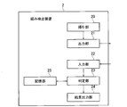
- FIG. 2 is a diagram showing a configuration of a looseness detection device according to the first embodiment.
- FIG. 3 is a diagram showing a configuration of a looseness detection system according to the first embodiment.
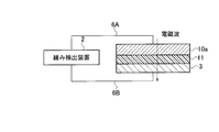
- FIG. 4 is a diagram showing an electric circuit formed in the first embodiment.
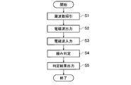
- FIG. 5 is a diagram showing an operation flow of the looseness detection method according to the first embodiment.
- FIG. 6 is a diagram showing the state transition of the bolt with the passage of time.
- FIG. 7 is a diagram showing an example of a method for determining looseness of bolts.
- FIG. 8 is a diagram showing an example of a method for determining looseness of bolts.
- FIG. 1 is a diagram showing a configuration of a looseness detection structure according to the first embodiment.
- FIG. 2 is a diagram showing a configuration of a looseness detection device according to the first embodiment.
- FIG. 3 is a diagram showing
- FIG. 9 is a diagram showing a configuration of a looseness detection structure according to a second embodiment.
- FIG. 10 is a diagram showing a configuration of a looseness detection system according to a second embodiment.
- FIG. 11 is a diagram showing a configuration of a looseness detection structure according to a third embodiment.
- FIG. 12 is a diagram showing a configuration of a looseness detection system according to a third embodiment.
- FIG. 13 is a diagram showing an electric circuit formed in the third embodiment.
- FIG. 14 is a diagram showing a configuration of a looseness detection structure according to a fourth embodiment.
- FIG. 15 is a diagram showing a configuration of a looseness detection structure according to a fifth embodiment.
- FIG. 16 is a diagram showing a configuration of a looseness detection system according to a fifth embodiment.
- FIG. 17 is a diagram showing a construction example of a looseness detection device.
- the present invention works on a hygroscopic resin material or the like on the seat surface or the like of the head of the bolt.
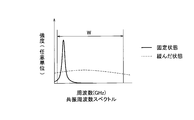
- a bolt is loosened, its hygroscopic resin material or the like continues to take in moisture in the air. Therefore, it is detected by electromagnetic waves such as microwaves that the dielectric constant of the hygroscopic resin material or the like has changed, and the looseness of the bolt is determined.
- FIG. 1 is a diagram showing a configuration of a looseness detection structure 1 according to the first embodiment.
- FIG. 1A is a side view and a partial cross-sectional view of the looseness detection structure 1.
- FIG. 1B is a cross-sectional view of the looseness detection structure 1 in AA'of FIG. 1A.
- the looseness detection structure 1 includes a looseness detection structure used for detecting looseness of a bolt fixing a steel plate to be fixed.
- the looseness detection structure 1 includes a metal bolt 10, a hygroscopic resin material 11, a first sealing material 12, and a second sealing material 13.
- the metallic bolt 10 includes a head portion 10a for rotating the bolt 10 about the body portion 10b as a central axis, and a body portion 10b on which a thread is formed.
- the bolt 10 can be realized by, for example, a general-purpose bolt distributed in the market.
- the hygroscopic resin material (hereinafter, hygroscopic material) 11 is arranged between the steel plate to be fixed and the head portion 10a of the bolt 10 for fixing the steel plate.
- the hygroscopic material 11 is attached to substantially the entire seat surface (the surface on the side having the body portion 10b) of the head portion 10a of the bolt 10 with an adhesive or the like, and is integrally attached to the bolt 10 as a part of the bolt 10. It has been incorporated.
- the hygroscopic material 11 is a material whose electrical characteristics change according to fluctuations in the force for tightening the bolt 10 with respect to the steel sheet.
- the hygroscopic material 11 is a hygroscopic resin material that takes in moisture in the air from an exposed surface as the force for tightening the bolt 10 decreases.
- the hygroscopic material 11 can be realized by using a material such as polyacrylate-based, polysulfonate-based, maleic anhydride-based, polyacrylamide-based, polyvinyl alcohol-based, polyethylene oxide-based, or polyamine-based material.
- the first sealing material 12 surrounds all the side surfaces of the hygroscopic material 11 so that the side surfaces of the hygroscopic material 11 are not exposed. It is arranged (attached / filled) on the side surface of the hygroscopic material 11 so as to cover the side surface of the hygroscopic material 11.
- the first sealing material 12 can be realized by, for example, a general-purpose sealing material distributed in the market.
- the second sealing material 13 is provided so that the lower surface of the hygroscopic material 11 (the surface on the side of the head portion 10a of the bolt 10 that is not in contact with the seating surface) is not exposed. It is arranged (attached / filled) on the lower surface of the hygroscopic material 11 so as to surround all the lower surfaces of the hygroscopic material 11 and to cover all the lower surfaces of the hygroscopic material 11.
- the second sealing material 13 can be realized by, for example, a general-purpose sealing material distributed in the market.
- the second sealing material 13 is for preventing the hygroscopic material 11 from taking in moisture in the air from the surface of the lower surface when the looseness detection structure 1 is not used (before tightening the bolt 10 and before construction). At the start of use of the looseness detection structure 1 (when the bolt 10 is tightened, during construction), the looseness detection structure 1 is peeled off to expose the lower surface of the hygroscopic material 11.
- FIG. 2 is a diagram showing a configuration of a looseness detection device 2 according to the first embodiment.
- the looseness detection device 2 is a looseness detection device that detects looseness of bolts.
- the looseness detection device 2 includes a sweep unit 20, an output unit 21, an input unit 22, a determination unit 23, a result output unit 24, and a storage unit 25.
- the sweep unit 20 is a functional unit that sweeps frequencies in a predetermined range.
- the output unit 21 is an electromagnetic wave having a frequency swept by the sweep unit 20, and is a functional unit that generates an electromagnetic wave used for detecting looseness of the bolt 10 and outputs the electromagnetic wave to the looseness detection structure 1. ..
- the output unit 21 generates an electromagnetic wave (high frequency signal) in a high frequency band such as a microwave, and propagates the electromagnetic wave to the head portion 10a of the bolt 10.
- the input unit 22 has a function of inputting an electromagnetic wave output from the output unit 21 to the looseness detection structure 1 and returned from the looseness detection structure 1.
- the input unit 22 inputs the electromagnetic wave returned through the steel plate to be fixed via the hygroscopic material 11.
- the determination unit 23 reads out the measured value of the electromagnetic wave measured at the start of use of the looseness detection structure 1 (when the bolt 10 is tightened, during construction) from the storage unit 25, and reads the measured value of the electromagnetic wave input from the input unit 22. It is a functional unit that determines looseness of the bolt 10 based on whether or not the resonance frequency is shifted or whether or not the resonance frequency is within a predetermined frequency range by comparing with the measured value of the electromagnetic wave at the start of use.
- the result output unit 24 is a functional unit that outputs the determination result of the looseness of the bolt 10 performed by the determination unit 23 to a display, a printing device, or the like.
- the storage unit 25 has a function of readablely storing the measured value of the electromagnetic wave measured at the start of use of the looseness detection structure 1 (when the bolt 10 is tightened, at the time of construction) in association with the measurement time.
- the storage unit 25 has a function of readablely storing the measured value of the electromagnetic wave input from the input unit 22 in association with the measurement time.
- Such a sweep unit 20, an output unit 21, and an input unit 22 can be realized by, for example, an electromagnetic wave control device, an electromagnetic wave control circuit, or the like that generates and inputs / outputs electromagnetic waves.
- the determination unit 23, the result output unit 24, and the storage unit 25 can be realized by a computer including a CPU, a memory, and the like.
- FIG. 3 is a diagram showing a configuration of a looseness detection system according to the first embodiment.
- the looseness detection system is configured by combining the looseness detection structure 1 shown in FIG. 1 and the looseness detection device 2 shown in FIG.
- the user peels off the second sealing material 13 to expose the lower surface of the hygroscopic material 11. Then, the user overlaps the first steel plate 3 and the second steel plate 4 to be fixed, penetrates the body portion 10b of the bolt 10 through the holes H1 and holes H2 for fixing them, and heads the bolt 10.
- the first steel plate 3 and the second steel plate 4 are fixed by rotating the portion 10a or the nut 5. As a result, the lower surface of the hygroscopic material 11 becomes unexposed again at the time of construction. Further, the side surface of the hygroscopic material 11 is also in an unexposed state by the first sealing material 12.
- the user connects the looseness detection device 2 and the head portion 10a of the bolt 10 by the first transmission line 6A, and connects the looseness detection device 2 and the first steel plate 3 by the second transmission line 6B.
- the looseness detection device 2 As a result, as shown in FIG. 4, the looseness detection device 2, the first transmission line 6A, the head portion 10a of the bolt 10, the hygroscopic material 11, the first steel plate 3, and the second transmission line With 6B, one electric circuit capable of propagating electromagnetic waves is formed.
- FIG. 5 is a diagram showing an operation flow of a looseness detection method performed by the looseness detection device 2 according to the first embodiment.
- Step S1 First, the sweep unit 20 sweeps frequencies in a predetermined range.
- an electromagnetic wave microwave or the like
- Step S3 Next, the input unit 22 inputs the electromagnetic wave returned from the first steel plate 3 via the second transmission line 6B.
- Step S4 the determination unit 23 reads the measured value of the electromagnetic wave measured at the time of construction from the storage unit 25, compares the measured value of the electromagnetic wave input in step S3 with the measured value of the electromagnetic wave at the time of the construction, and compares the resonance frequency.
- the looseness of the bolt 10 is determined based on whether or not the frequency has shifted or whether or not the resonance frequency is within a predetermined frequency range.
- Step S5 Finally, the result output unit 24 outputs the determination result of step S4 to the screen of the display.
- the lower surface of the hygroscopic material 11 comes into contact with air, and the hygroscopic material 11 absorbs moisture and rain in the air from the surface of the exposed lower surface.
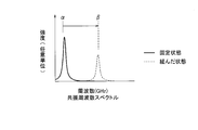
- the dielectric constant of the hygroscopic material 11 fluctuates, or the hygroscopic material 11 expands. Therefore, an electromagnetic wave such as a microwave is propagated to the hygroscopic material 11 to detect the presence or absence of a resonance frequency shift (peak shift) due to a difference in the dielectric constant of the hygroscopic material 11. That is, when the hygroscopic material 11 absorbs moisture, its own dielectric constant increases, so that the effective wavelength of the propagating electromagnetic wave becomes short, and the resonance frequency shifts to the short wavelength side. The presence or absence of this resonance frequency shift is detected.
- the first sealing material 12 In the present embodiment, the case where the first sealing material 12 is arranged on the side surface of the hygroscopic material 11 has been described. On the other hand, when the bolt 10 is tightened, the thickness of the hygroscopic material 11 becomes very thin, so that the amount of water taken in from the side surface of the hygroscopic material 11 is extremely small compared to the amount of water taken in from the lower surface of the hygroscopic material 11. .. Therefore, if the measured value when a small amount of water is taken in from the side surface of the hygroscopic material 11 is defined as the measured value at the time of construction, the first sealing material 12 does not necessarily have to be used.
- the hygroscopic material 11 has been described as an example.
- any material other than the hygroscopic material 11 may be used as long as it is a material whose electrical characteristics change according to fluctuations in the force for tightening the bolt 10 with respect to the steel plate.
- an insulator such as a piezoelectric material or a ferroelectric material that conducts electricity when pressure is applied is arranged on the seat surface of the head portion 10a of the bolt 10.
- the ferroelectric substance can be realized, for example, by using a relaxor ferroelectric substance as a material.
- the dielectric constant of the insulator is low because pressure is applied between the head portion 10a of the bolt 10 and the first steel plate 3.
- the applied pressure is reduced, so that the dielectric constant of the insulator is increased. Therefore, electromagnetic waves such as microwaves are propagated, and the presence or absence of a shift in the resonance frequency due to the difference in the dielectric constant of the insulator is detected.
- the hygroscopic material 11 has been described as an example.
- any material other than the hygroscopic material 11 may be used as long as it is a material whose electrical characteristics change according to fluctuations in the force for tightening the bolt 10 with respect to the steel plate.
- an insulator such as a Mott insulator (Mott insulator) whose electrical resistance is reduced by pressurization is arranged on the seat surface of the head portion 10a of the bolt 10.
- Mott insulator can be realized by using a material such as ReNiO 3.
- FIG. 9 is a diagram showing the configuration of the looseness detection structure 1 according to the second embodiment.
- the antenna 7 is added to the looseness detection structure 1 described in the first embodiment.
- the antenna 7 is connected to the head portion 10a of the bolt 10 by using the first transmission line 6A.
- the antenna 7 has a function of wirelessly receiving an electromagnetic wave used for detecting looseness of the bolt 10 and wirelessly transmitting an electromagnetic wave that has passed through the hygroscopic material 11.
- the antenna 7 can be realized by, for example, a general-purpose antenna rod distributed in the market. If necessary, a transmission / reception circuit for transmitting / receiving electromagnetic waves wirelessly may be further provided.
- the configuration of the looseness detection structure 1 other than the antenna 7 and the transmission / reception circuit is the same as the configuration of the looseness detection structure 1 described in the first embodiment.
- FIG. 10 is a diagram showing a configuration of a looseness detection system according to a second embodiment.
- the looseness detection device 2 according to the second embodiment is arranged inside an unmanned aerial vehicle and a drone 30 which is an unmanned aerial vehicle.
- an antenna that wirelessly transmits an electromagnetic wave used for detecting the looseness of the bolt 10 to the looseness detection structure 1 and wirelessly receives the electromagnetic wave returned from the looseness detection structure 1. to add.
- a transmission / reception circuit for transmitting / receiving electromagnetic waves wirelessly may be further provided.
- This antenna and transmission / reception circuit can also be realized by, for example, a general-purpose antenna rod and a wireless transmission / reception circuit distributed in the market.
- the configuration of the looseness detection device 2 other than the antenna and the transmission / reception circuit is the same as the configuration of the looseness detection device 2 described in the first embodiment.
- the antenna 7 added to the looseness detection structure 1 is connected to the head portion 10a of the bolt 10 by using the first transmission line 6A, and is connected to the first steel plate 3 by using the second transmission line 6B. Be connected.
- the looseness detection device 2 and the looseness detection structure 1 wirelessly transmit and receive electromagnetic waves to each other.
- the other operations are the same as the operations described in the first embodiment.
- the looseness detection device 2 is arranged inside the drone 30 .
- the looseness detection device 2 may be mounted on an external medium such as a mobile inspection vehicle.
- FIG. 11 is a diagram showing the configuration of the looseness detection structure 1 according to the third embodiment.
- FIG. 11A is a side view and a cross-sectional view of the looseness detection structure 1.
- FIG. 1B is a bottom view of FIG. 1A.
- the looseness detection structure 1 includes a looseness detection structure used for detecting looseness of a bolt fixing a steel plate to be fixed.
- the loosening detection structure 1 includes a metallic bolt 10.
- the metallic bolt 10 includes a head portion 10a for rotating the bolt 10 about the body portion 10b as a central axis, and a body portion 10b on which a thread is formed.
- the bolt 10 can be realized by, for example, a general-purpose bolt distributed in the market.
- the bolt 10 is composed of a metallic inner layer 14, a hygroscopic material 11, a metallic outer layer 15, and a second sealing material 13.
- the inner layer 14 is formed inside the bolt 10.
- the inner layer 14 can be realized, for example, by pouring a metal material into a T-shaped mold.
- the hygroscopic material 11 is arranged in a hollow region between the inner layer 14 of the bolt 10 and the outer layer 15 of the bolt 10.
- the hygroscopic material 11 is sealed in the hollow region by the inner layer 14 of the bolt 10 and the outer layer 15 of the bolt 10, and is integrally incorporated in the bolt 10 as a part of the bolt 10.
- the hygroscopic material 11 is a material whose electrical characteristics change according to fluctuations in the force for tightening the bolt 10 with respect to the steel sheet.
- the hygroscopic material 11 is a hygroscopic resin material that takes in moisture in the air from an exposed surface as the force for tightening the bolt 10 decreases, as in the first embodiment.
- the hygroscopic material 11 can be realized by using a material such as polyacrylate-based, polysulfonate-based, maleic anhydride-based, polyacrylamide-based, polyvinyl alcohol-based, polyethylene oxide-based, or polyamine-based material.
- the outer layer 15 forms the outside of the bolt 10.
- the outer layer 15 is formed with a plurality of air holes H3 for passing and inputting air at a portion forming the seating surface of the head portion 10a of the bolt 10.
- the outer layer 15 can be realized by pouring a metal material into a bolt-shaped mold.
- the second sealing material 13 is arranged (attached / filled) inside a plurality of air holes H3 so that the hygroscopic material 11 arranged inside the bolt 10 is not exposed.
- the second sealing material 13 can be realized by, for example, a general-purpose sealing material distributed in the market.
- the second sealing material 13 prevents the hygroscopic material 11 from taking in moisture in the air through the air holes H3 when the looseness detection structure 1 is not used (before tightening the bolt 10 and before construction). This is for the purpose, and at the start of use of the looseness detection structure 1 (when the bolt 10 is tightened, at the time of construction), it is removed to expose the hygroscopic material 11 in the bolt 10.
- the configuration of the looseness detection device 2 according to the third embodiment is the same as the configuration of the looseness detection device 2 according to the first embodiment.
- FIG. 12 is a diagram showing a configuration of a looseness detection system according to a third embodiment.
- the user When fixing the steel plate to be fixed with the bolt 10, the user removes the second sealing material 13 to expose the hygroscopic material 11 in the bolt 10. Then, the user overlaps the first steel plate 3 and the second steel plate 4 to be fixed, penetrates the body portion 10b of the bolt 10 through the holes H1 and holes H2 for fixing them, and heads the bolt 10. The first steel plate 3 and the second steel plate 4 are fixed by rotating the portion 10a or the nut 5. As a result, the hygroscopic material 11 is again in an unexposed state at the time of construction.
- the user connects the looseness detection device 2 and the inner layer 14 of the bolt 10 with the first transmission line 6A, and connects the looseness detection device 2 and the outer layer 15 of the bolt 10 with the second transmission line 6B.
- the looseness detection device 2 As a result, as shown in FIG. 13, the looseness detection device 2, the first transmission line 6A, the inner layer 14 of the bolt 10, the hygroscopic material 11, the outer layer 15 of the bolt 10, and the second transmission line 6B
- one electric circuit capable of propagating electromagnetic waves is formed.
- the hygroscopic material 11 comes into contact with air, and the hygroscopic material 11 absorbs moisture and rain in the air from the exposed surface. As a result, the hygroscopic material 11 expands, and the dielectric constant of the hygroscopic material 11 fluctuates. Therefore, the surface of the head portion 10a of the bolt 10 is grounded, a voltage is induced between the surface of the head portion 10a of the bolt 10 and the hygroscopic material 11 embedded in the bolt 10, and the frequency characteristics of the electromagnetic wave propagating to the hygroscopic material 11 are observed. Then, it is determined that the bolt 10 is loosened and the dielectric constant of the hygroscopic material 11 is changed by the shift of the resonance frequency or the presence or absence of the resonance frequency in the observation frequency range.
- the specific operation of the looseness detection device 2 according to the third embodiment is the same as the operation described in the first embodiment.
- an insulator such as a piezoelectric material or a ferroelectric material that conducts electricity when pressure is applied may be arranged (embedded) in the bolt 10.
- the pressure on the insulator also fluctuates, so that the dielectric constant of the insulator changes. Therefore, electromagnetic waves such as microwaves are propagated, and the presence or absence of a shift in the resonance frequency due to the difference in the dielectric constant of the insulator is detected.
- the insulator In the case of the insulator, it is determined based on the presence or absence of pressure on the insulator, and the uptake of moisture in the air such as the hygroscopic material 11 is not a determination factor, so that it is not necessary to provide the air hole H3.
- an insulator such as a Mott insulator (Mott insulator) whose electrical resistance is reduced by pressurization is arranged (embedded) in the bolt 10. May be good.
- Mott insulator Mott insulator
- the pressure on the insulator also fluctuates, so that the dielectric constant of the insulator changes. Therefore, electromagnetic waves such as microwaves are propagated, and the presence or absence of a shift in the resonance frequency due to the difference in the dielectric constant of the insulator is detected.
- the insulator In the case of the insulator, it is determined based on the presence or absence of pressure on the insulator, and the uptake of moisture in the air such as the hygroscopic material 11 is not a determination factor, so that it is not necessary to provide the air hole H3.
- FIG. 14 is a diagram showing the configuration of the looseness detection structure 1 according to the fourth embodiment.
- the antenna 7 is added to the looseness detection structure 1 described in the third embodiment as in the second embodiment.
- the antenna 7 is connected to the inner layer 14 of the bolt 10 by using the first transmission line 6A, and is connected to the outer layer 15 of the bolt 10 by using the second transmission line 6B.
- the antenna 7 can be realized by, for example, a general-purpose antenna rod distributed in the market. If necessary, a transmission / reception circuit for transmitting / receiving electromagnetic waves wirelessly may be further provided.
- the configuration of the looseness detection structure 1 other than the antenna 7 and the transmission / reception circuit is the same as the configuration of the looseness detection structure 1 described in the first embodiment.
- the looseness detection device 2 according to the fourth embodiment is arranged inside the drone 30 which is an unmanned aerial vehicle and an unmanned flying object, as in the second embodiment.
- an antenna that wirelessly transmits an electromagnetic wave used for detecting the looseness of the bolt 10 to the looseness detection structure 1 and wirelessly receives the electromagnetic wave returned from the looseness detection structure 1. to add.
- a transmission / reception circuit for transmitting / receiving electromagnetic waves wirelessly may be further provided.
- This antenna and transmission / reception circuit can also be realized by, for example, a general-purpose antenna rod and a wireless transmission / reception circuit distributed in the market.
- the configuration of the looseness detection device 2 other than the antenna and the transmission / reception circuit is the same as the configuration of the looseness detection device 2 described in the first embodiment.
- the looseness detection device 2 and the looseness detection structure 1 wirelessly transmit and receive electromagnetic waves to each other, as in the second embodiment.
- the other operations are the same as the operations described in the first embodiment.
- the looseness detection device 2 may be mounted on an external medium such as a mobile inspection vehicle instead of the drone 30.
- the washer Since the washer is arranged between the head of the bolt and the steel plate, it is positionally the same as the hygroscopic material 11 is arranged between the head of the bolt and the steel plate. Therefore, even when the hygroscopic material 11 is incorporated as a part of the washer, the same effect as that of the first to fourth embodiments can be obtained.
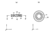
- FIG. 15 is a diagram showing the configuration of the looseness detection structure 1 according to the fifth embodiment.
- FIG. 15A is a side view and a partial cross-sectional view of the looseness detection structure 1.
- 15 (b) is a cross-sectional view of the looseness detection structure 1 in BB'of FIG. 15 (a).
- the looseness detection structure 1 includes a looseness detection structure used for detecting looseness of a bolt fixing a steel plate to be fixed.
- the loosening detection structure 1 includes a metallic washer 51, a hygroscopic material 11, and a second sealing material 13.
- the washer 51 has a donut-shaped shape as shown in FIG. 1 (b).
- the outer diameter of the washer 51 is larger than the diameter of the head portion 10a of the bolt 10.
- the inner diameter of the washer 51 is smaller than the diameter of the head portion 10a of the bolt 10.
- the washer 51 can be realized by, for example, a general-purpose washer distributed in the market.
- the hygroscopic material 11 has a donut-shaped shape and is arranged inside the washer 51.
- the hygroscopic material 11 is attached to the inner surface of the washer 51 with an adhesive or the like, and is integrally incorporated in the washer as a part of the washer.
- the hygroscopic material 11 is a material whose electrical characteristics change according to fluctuations in the force for tightening the bolt 10 with respect to the steel sheet.
- the hygroscopic material 11 is a hygroscopic resin material that takes in moisture in the air from an exposed surface as the force for tightening the bolt 10 decreases.
- the hygroscopic material 11 can be realized by using a material such as polyacrylate-based, polysulfonate-based, maleic anhydride-based, polyacrylamide-based, polyvinyl alcohol-based, polyethylene oxide-based, or polyamine-based material.
- the hygroscopic material 11 is arranged (attached / filled) on the upper surface and the lower surface of the hygroscopic material 11 so as to cover all the upper surfaces and all the lower surfaces of the hygroscopic material 11.
- the second sealing material 13 can be realized by, for example, a general-purpose sealing material distributed in the market.
- the second sealing material 13 prevents the hygroscopic material 11 from taking in moisture in the air from the surface of the upper surface or the surface of the lower surface when the looseness detection structure 1 is not used (before tightening the bolt 10 and before construction). This is to prevent the looseness detection structure 1 from being peeled off at the start of use (when the bolt 10 is tightened or during construction) to expose the upper and lower surfaces of the hygroscopic material 11.
- the configuration of the looseness detection device 2 according to the fifth embodiment is the same as the configuration of the looseness detection device 2 according to the first embodiment.
- FIG. 16 is a diagram showing a configuration of a looseness detection system according to a fifth embodiment.
- the user When fixing the steel plate to be fixed with the bolt 10, the user removes the second sealing material 13 to expose the upper surface and the lower surface of the hygroscopic material 11 in the washer 51. Then, the user superimposes the first steel plate 3 and the second steel plate 4 to be fixed, penetrates the body portion 10b of the bolt 10 through the washer 51 and the holes H1 and holes H2 for fixing them, and bolts. The head portion 10a or the nut 5 of the 10 is rotated to fix the first steel plate 3 and the second steel plate 4. As a result, the hygroscopic material 11 in the washer 51 becomes unexposed again at the time of construction.
- the user connects the looseness detection device 2 and the head portion 10a of the bolt 10 by the first transmission line 6A, and connects the looseness detection device 2 and the first steel plate 3 by the second transmission line 6B.
- electromagnetic waves can be propagated by the looseness detection device 2, the first transmission line 6A, the head portion 10a of the bolt 10, the hygroscopic material 11, the first steel plate 3, and the second transmission line 6B.
- An electric circuit is formed.
- the hygroscopic material 11 comes into contact with air, and the hygroscopic material 11 absorbs moisture and rain in the air from the exposed surface.
- the dielectric constant of the hygroscopic material 11 fluctuates, or the hygroscopic material 11 expands. Therefore, an electromagnetic wave such as a microwave is propagated to the hygroscopic material 11 to detect the presence or absence of a shift in the resonance frequency due to the difference in the dielectric constant of the hygroscopic material 11. That is, when the hygroscopic material 11 absorbs moisture, its own dielectric constant increases, so that the effective wavelength of the propagating electromagnetic wave becomes short, and the resonance frequency shifts to the short wavelength side. The presence or absence of this resonance frequency shift is detected.
- the specific operation of the looseness detection device 2 according to the fifth embodiment is the same as the operation described in the first embodiment.
- an insulator such as a piezoelectric material or a ferroelectric material that conducts electricity when pressure is applied may be arranged (embedded) in the washer 51.
- the thickness of the insulator is made larger than the thickness of the washer 51 so that pressure is applied to the insulator when the bolt 10 is tightened.
- the pressure on the insulator also fluctuates, so that the dielectric constant of the insulator changes. Therefore, electromagnetic waves such as microwaves are propagated, and the presence or absence of a shift in the resonance frequency due to the difference in the dielectric constant of the insulator is detected.
- an insulator such as a Mott insulator (Mott insulator) whose electrical resistance is reduced by pressurization is arranged (embedded) in the bolt 10. May be good.
- the thickness of the insulator is made larger than the thickness of the washer 51 so that pressure is applied to the insulator when the bolt 10 is tightened.
- the pressure on the insulator also fluctuates, so that the dielectric constant of the insulator changes. Therefore, electromagnetic waves such as microwaves are propagated, and the presence or absence of a shift in the resonance frequency due to the difference in the dielectric constant of the insulator is detected.
- an antenna for wirelessly transmitting and receiving electromagnetic waves and a transmission / reception circuit used for wirelessly transmitting and receiving electromagnetic waves may be added to the looseness detection structure 1 and the looseness detection device 2, respectively.
- the bolt 10 itself may be made of a material such as an insulator that conducts electricity when pressure is applied and an insulator whose electrical resistance decreases when pressure is applied.
- all the configurations of the first to fifth embodiments may be combined.
- the steel plate 3 to be fixed is arranged between the head portion 10a of the metallic bolt 10 for fixing the steel plate 3. It is attached to the seat surface of the head portion 10a of the bolt 10 or attached to the washer 51 arranged between the steel plate 3 and the head portion 10a of the bolt 10, and is electrically attached according to the fluctuation of the force for tightening the bolt 10 with respect to the steel plate 3. Since the material 11 whose characteristics change is provided, it is possible to provide a technique capable of easily detecting looseness of a bolt.
- the bolt 10 or the washer 51 Since it is integrally incorporated as a part, that is, since the bolt 10 main body or the washer 51 main body has a loosening detection structure, it is necessary to detect looseness of the bolt at the time of tightening the bolt to fix the steel plate. Since it is not necessary to bother to attach the material 11 used for the above and it is sufficient to replace the bolt, it is possible to inspect the looseness of the bolt with a simple operation. Further, since the loosened gap portion expands due to the expansion of the material 11, the tightening force can be returned with a certain weak force. Further, at the time of inspection, the material 11 is dried and the resin of the material 11 is dehumidified so that the material 11 can be reused by tightening again.
- the material 11 is a hygroscopic resin material that takes in moisture in the air from an exposed surface as the force for tightening the bolt 10 decreases, and an insulator that conducts electricity when pressure is applied. Since it is one of the insulators whose electrical resistance is reduced by pressurization, it is possible to provide a technique capable of easily and surely detecting loosening of bolts.
- the metallic inner layer 14 formed inside the bolt 10 and the metallic outer layer 15 forming the outside of the bolt 10 Since the material 11 is provided between the materials and whose electrical characteristics change according to the fluctuation of the force for tightening the bolt with respect to the steel plate to be fixed, it is possible to provide a technique capable of easily detecting the looseness of the bolt.
- the material 11 is a hygroscopic resin material that takes in moisture in the air from an exposed surface as the force for tightening the bolt 10 decreases, and an insulator that conducts electricity when pressure is applied.
- a hygroscopic resin material which is one of the insulators whose electrical resistance is reduced by pressurization, an air hole H3 for passing air is formed in the outer layer 15 constituting the seating surface of the head portion 10a of the bolt 10. Therefore, it is possible to provide a technique that can easily and surely detect loosening of bolts.
- the loosening detection structure 1 further includes an antenna 7 that wirelessly receives the electromagnetic wave used for detecting the looseness of the bolt and wirelessly transmits the electromagnetic wave that has passed through the material 11, so that the loosening of the bolt is provided.
- it is sufficient to connect the antenna 7 only to the bolt 10 it is possible to eliminate the trouble of connecting the looseness detection device 2 to the steel plate 3 to be fixed. It is only necessary to tighten the bolts 10, and it is possible to easily inspect a huge number of bolts for looseness from a remote location at a time.
- the looseness detection structure 1 is It is arranged between the steel plate 3 to be fixed and the head portion 10a of the metallic bolt 10 that fixes the steel plate 3, and is attached to the seat surface of the head portion 10a of the bolt 10 or with the steel plate 3 and the head portion 10a of the bolt 10.
- the material 11 attached to the washer 51 arranged between the steel plates 3 and whose electrical characteristics change according to the fluctuation of the force for tightening the bolt 10 with respect to the steel plate 3, or the metallic inner layer 14 formed inside the bolt 10.
- a looseness detection device 2 is provided with a material 11 which is arranged between the metal outer layer 15 forming the outside of the bolt 10 and whose electrical characteristics change according to fluctuations in the force for tightening the bolt 10 with respect to the steel plate 3 to be fixed. Measures the output unit 21 that outputs an electromagnetic wave used for detecting the looseness of the bolt 10, the input unit 22 that inputs the electromagnetic wave returned via the material 11, and the measured value of the input electromagnetic wave when the bolt 10 is tightened. Since it is provided with a determination unit 23 for determining looseness of the bolt 10 based on whether or not the resonance frequency is shifted or whether or not the resonance frequency is within a predetermined frequency range as compared with the measured value of the electromagnetic wave. It is possible to provide a technique that can easily detect loosening of a bolt.
- the looseness detection structure 1 is the steel plate 3 and the steel plate 3 to be fixed.
- a washer 51 that is placed between the head portion 10a of the metal bolt 10 and attached to the seat surface of the head portion 10a of the bolt 10 or placed between the steel plate 3 and the head portion 10a of the bolt 10.
- a material 11 whose electrical characteristics change according to fluctuations in the force for tightening the bolt 10 with respect to the steel plate 3, or a metal forming an inner layer 14 formed inside the bolt 10 and a metal forming the outside of the bolt 10.
- a material 11 is provided between the outer layer 15 and the material 11 whose electrical characteristics change according to fluctuations in the force for tightening the bolt 10 with respect to the steel plate 3 to be fixed, and the looseness detecting device 2 detects the looseness of the bolt 10.
- the step of outputting the electromagnetic wave used for the bolt 10 and the step of inputting the electromagnetic wave returned through the material 11 and the measured value of the input electromagnetic wave are compared with the measured value of the electromagnetic wave measured when the bolt 10 is tightened, and the resonance frequency is determined. Since the step of determining the looseness of the bolt is performed based on whether or not the bolt has been shifted or whether or not the resonance frequency is within a predetermined frequency range, it is possible to provide a technique capable of easily detecting the looseness of the bolt.
- the present invention is not limited to the above embodiment, and many modifications can be made within the scope of the gist thereof.
- the looseness detection device 2 of the present embodiment described above has, for example, as shown in FIG. 17, a CPU (Central Processing Unit) 901, a memory 902, and a storage 903 (HDD; Hard Disk Drive, SSD; Solid State Drive).
- a general-purpose computer system including a communication device 904, an input device 905, and an output device 906 can be used.
- the memory 902 and the storage 903 are storage devices.
- each function of the looseness detection device 2 is realized by the CPU 901 executing a predetermined program loaded on the memory 902.
- the looseness detection device 2 may be mounted on one computer or may be mounted on a plurality of computers. Further, the looseness detection device 2 may be a virtual machine mounted on a computer.
- the program for the looseness detection device 2 can be stored in a computer-readable recording medium such as an HDD, SSD, USB (Universal Serial Bus) memory, CD (Compact Disc), or DVD (Digital Versatile Disc), or via a network. It can also be delivered.
- Loose detection structure 10 Bolt 10a: Bolt head 10b: Bolt body 11: Moisture absorbing material 12: First sealing material 13: Second sealing material 14: Bolt inner layer 15: Bolt outer layer 2 : Looseness detection device 20: Sweep unit 21: Output unit 22: Input unit 23: Judgment unit 24: Result output unit 25: Storage unit 3: First steel plate 4: Second steel plate 5: Nut 6A: First transmission Line 6B: Second transmission line 7: Antenna 30: Drone 51: Washer 901: CPU 902: Memory 903: Storage 904: Communication device 905: Input device 906: Output device H1: Hole for fixing the first steel plate H2: Hole for fixing the second steel plate H3: Air hole in the outer layer of the bolt
Landscapes
- Physics & Mathematics (AREA)
- General Physics & Mathematics (AREA)
- Electromagnetism (AREA)
- Health & Medical Sciences (AREA)
- Life Sciences & Earth Sciences (AREA)
- Chemical & Material Sciences (AREA)
- Analytical Chemistry (AREA)
- Biochemistry (AREA)
- General Health & Medical Sciences (AREA)
- Immunology (AREA)
- Pathology (AREA)
- Geophysics And Detection Of Objects (AREA)
- Testing Of Devices, Machine Parts, Or Other Structures Thereof (AREA)
Priority Applications (3)
| Application Number | Priority Date | Filing Date | Title |
|---|---|---|---|
| JP2021554528A JP7376813B2 (ja) | 2019-11-08 | 2019-11-08 | 緩み検出構造、緩み検出システム、および、緩み検出方法 |
| US17/774,670 US11976993B2 (en) | 2019-11-08 | 2019-11-08 | Loosening detection structure, loosening detection system and method |
| PCT/JP2019/043797 WO2021090468A1 (ja) | 2019-11-08 | 2019-11-08 | 緩み検出構造、緩み検出システム、および、緩み検出方法 |
Applications Claiming Priority (1)
| Application Number | Priority Date | Filing Date | Title |
|---|---|---|---|
| PCT/JP2019/043797 WO2021090468A1 (ja) | 2019-11-08 | 2019-11-08 | 緩み検出構造、緩み検出システム、および、緩み検出方法 |
Publications (1)
| Publication Number | Publication Date |
|---|---|
| WO2021090468A1 true WO2021090468A1 (ja) | 2021-05-14 |
Family
ID=75848290
Family Applications (1)
| Application Number | Title | Priority Date | Filing Date |
|---|---|---|---|
| PCT/JP2019/043797 Ceased WO2021090468A1 (ja) | 2019-11-08 | 2019-11-08 | 緩み検出構造、緩み検出システム、および、緩み検出方法 |
Country Status (3)
| Country | Link |
|---|---|
| US (1) | US11976993B2 (https=) |
| JP (1) | JP7376813B2 (https=) |
| WO (1) | WO2021090468A1 (https=) |
Cited By (1)
| Publication number | Priority date | Publication date | Assignee | Title |
|---|---|---|---|---|
| CN113311026A (zh) * | 2021-05-27 | 2021-08-27 | 宁夏海豚智能科技有限公司 | 螺栓松动检测系统及方法 |
Families Citing this family (3)
| Publication number | Priority date | Publication date | Assignee | Title |
|---|---|---|---|---|
| CN115931204A (zh) * | 2022-12-29 | 2023-04-07 | 安徽精亘机械科技有限公司 | 一种基于振荡电路的智慧螺栓预紧力测量装置 |
| CN117823804B (zh) * | 2023-12-14 | 2026-02-24 | 湖北三江航天江北机械工程有限公司 | 车载lng气瓶保护罩盖板及安装方法 |
| CN120008790B (zh) * | 2025-04-14 | 2025-06-24 | 北京交通大学 | 频率-应力映射的螺栓紧固状态无源无线检测装置及方法 |
Citations (6)
| Publication number | Priority date | Publication date | Assignee | Title |
|---|---|---|---|---|
| JPS6039523A (ja) * | 1983-08-12 | 1985-03-01 | Yahata Tekko Kk | 締結部の緩み検出方法 |
| JPH03114031A (ja) * | 1989-09-28 | 1991-05-15 | Toshiba Corp | 有機非線形光学材料 |
| JP2013210234A (ja) * | 2012-03-30 | 2013-10-10 | Seiko Epson Corp | 締め付け緩み検出センサー及び締め付け緩み検出システム |
| US20140190267A1 (en) * | 2013-01-09 | 2014-07-10 | King Abdulaziz City For Science And Technology | Fastener tension monitoring system |
| JP2014228465A (ja) * | 2013-05-24 | 2014-12-08 | イナバゴム株式会社 | 締付固定部材の緩み検出装置 |
| JP2015025477A (ja) * | 2013-07-24 | 2015-02-05 | 信弘 人見 | 螺子の点検用塗膜及び螺子の点検用塗膜の塗布方法 |
Family Cites Families (6)
| Publication number | Priority date | Publication date | Assignee | Title |
|---|---|---|---|---|
| US4637391A (en) * | 1986-04-03 | 1987-01-20 | Schlein Allen P | Surgical saw blade |
| JPH03114031U (https=) * | 1990-03-08 | 1991-11-22 | ||
| US6925395B2 (en) * | 2002-10-15 | 2005-08-02 | Canberra Aquila, Inc. | Apparatus and method for measuring the torque applied to bolts |
| JP4039965B2 (ja) * | 2003-03-10 | 2008-01-30 | 財団法人鉄道総合技術研究所 | 構造物外力検知装置、及び構造物の外力検知方法 |
| GB0525691D0 (en) * | 2005-12-16 | 2006-01-25 | Airbus Uk Ltd | A fastener assembly |
| US10740577B2 (en) * | 2016-07-12 | 2020-08-11 | Palo Alto Research Center Incorporated | Passive sensor tag system |
-
2019
- 2019-11-08 US US17/774,670 patent/US11976993B2/en active Active
- 2019-11-08 WO PCT/JP2019/043797 patent/WO2021090468A1/ja not_active Ceased
- 2019-11-08 JP JP2021554528A patent/JP7376813B2/ja active Active
Patent Citations (6)
| Publication number | Priority date | Publication date | Assignee | Title |
|---|---|---|---|---|
| JPS6039523A (ja) * | 1983-08-12 | 1985-03-01 | Yahata Tekko Kk | 締結部の緩み検出方法 |
| JPH03114031A (ja) * | 1989-09-28 | 1991-05-15 | Toshiba Corp | 有機非線形光学材料 |
| JP2013210234A (ja) * | 2012-03-30 | 2013-10-10 | Seiko Epson Corp | 締め付け緩み検出センサー及び締め付け緩み検出システム |
| US20140190267A1 (en) * | 2013-01-09 | 2014-07-10 | King Abdulaziz City For Science And Technology | Fastener tension monitoring system |
| JP2014228465A (ja) * | 2013-05-24 | 2014-12-08 | イナバゴム株式会社 | 締付固定部材の緩み検出装置 |
| JP2015025477A (ja) * | 2013-07-24 | 2015-02-05 | 信弘 人見 | 螺子の点検用塗膜及び螺子の点検用塗膜の塗布方法 |
Cited By (1)
| Publication number | Priority date | Publication date | Assignee | Title |
|---|---|---|---|---|
| CN113311026A (zh) * | 2021-05-27 | 2021-08-27 | 宁夏海豚智能科技有限公司 | 螺栓松动检测系统及方法 |
Also Published As
| Publication number | Publication date |
|---|---|
| JP7376813B2 (ja) | 2023-11-09 |
| US11976993B2 (en) | 2024-05-07 |
| US20220390307A1 (en) | 2022-12-08 |
| JPWO2021090468A1 (https=) | 2021-05-14 |
Similar Documents
| Publication | Publication Date | Title |
|---|---|---|
| WO2021090468A1 (ja) | 緩み検出構造、緩み検出システム、および、緩み検出方法 | |
| US7725269B2 (en) | Sensor infrastructure | |
| JP7144705B2 (ja) | トランスデューサ、緩み検出システム、および緩み検出方法 | |
| CN110346700A (zh) | 变压器放油阀式局放监测与定位系统用复合传感器 | |
| US10161919B2 (en) | Acoustic emission sensors with integral acoustic generators | |
| KR102135587B1 (ko) | 가스량 측정이 가능한 고감도 초음파 센서 | |
| US20120286764A1 (en) | Apparatus for detecting partial discharge for electric power devices | |
| US11105788B2 (en) | Apparatus for detecting internal defect in transformer | |
| KR101877769B1 (ko) | 복합 다중 주파수 초음파 위상배열 영상화 장치 | |
| KR101158540B1 (ko) | 전력설비 열화진단용 광대역 초음파 스캐너 | |
| JP2010096571A (ja) | 検査装置、ならびに、検査方法 | |
| EP4032624A1 (en) | Flexoelectricity ultrasonic transducer imaging system | |
| US12187082B2 (en) | Tire with built-in antenna | |
| Ramesh et al. | Life prediction analysis on underwater acoustic sensors and its experimental validation | |
| CN210775337U (zh) | 一种可调频超声波探头 | |
| RU2601270C1 (ru) | Преобразователь акустической эмиссии повышенной надежности | |
| US9316622B2 (en) | Microwave vibration sensors | |
| Du et al. | A high sensitivity and signal-to-noise ratio vector hydrophone combined with flexoelectricity and piezoelectricity | |
| CN118393001A (zh) | 一种空气耦合声发射传感器 | |
| WO2015155522A1 (en) | Device for inspecting a structure | |
| CN116609436A (zh) | 基于压电换能原理的管道缺陷超声导波检测装置及检测方法 | |
| KR101479898B1 (ko) | 흡음재를 이용한 수중청음기 신호조절판 제작방법 | |
| KR20230167121A (ko) | 초음파 검사 장치 | |
| Paget et al. | Behavior of an embedded piezoceramic transducer for Lamb wave generation in mechanical loading | |
| KR101258416B1 (ko) | 구조물 손상 감지장치 |
Legal Events
| Date | Code | Title | Description |
|---|---|---|---|
| 121 | Ep: the epo has been informed by wipo that ep was designated in this application |
Ref document number: 19951877 Country of ref document: EP Kind code of ref document: A1 |
|
| ENP | Entry into the national phase |
Ref document number: 2021554528 Country of ref document: JP Kind code of ref document: A |
|
| NENP | Non-entry into the national phase |
Ref country code: DE |
|
| 122 | Ep: pct application non-entry in european phase |
Ref document number: 19951877 Country of ref document: EP Kind code of ref document: A1 |