WO2021085467A1 - 店舗監視システム、店舗監視装置、店舗監視方法及び記録媒体 - Google Patents
店舗監視システム、店舗監視装置、店舗監視方法及び記録媒体 Download PDFInfo
- Publication number
- WO2021085467A1 WO2021085467A1 PCT/JP2020/040412 JP2020040412W WO2021085467A1 WO 2021085467 A1 WO2021085467 A1 WO 2021085467A1 JP 2020040412 W JP2020040412 W JP 2020040412W WO 2021085467 A1 WO2021085467 A1 WO 2021085467A1
- Authority
- WO
- WIPO (PCT)
- Prior art keywords
- image
- shelf
- product
- store
- captured
- Prior art date
- Legal status (The legal status is an assumption and is not a legal conclusion. Google has not performed a legal analysis and makes no representation as to the accuracy of the status listed.)
- Ceased
Links
Images


Classifications
-
- G—PHYSICS
- G06—COMPUTING OR CALCULATING; COUNTING
- G06T—IMAGE DATA PROCESSING OR GENERATION, IN GENERAL
- G06T5/00—Image enhancement or restoration
- G06T5/80—Geometric correction
-
- G—PHYSICS
- G06—COMPUTING OR CALCULATING; COUNTING
- G06V—IMAGE OR VIDEO RECOGNITION OR UNDERSTANDING
- G06V10/00—Arrangements for image or video recognition or understanding
- G06V10/20—Image preprocessing
- G06V10/26—Segmentation of patterns in the image field; Cutting or merging of image elements to establish the pattern region, e.g. clustering-based techniques; Detection of occlusion
- G06V10/273—Segmentation of patterns in the image field; Cutting or merging of image elements to establish the pattern region, e.g. clustering-based techniques; Detection of occlusion removing elements interfering with the pattern to be recognised
-
- A—HUMAN NECESSITIES
- A47—FURNITURE; DOMESTIC ARTICLES OR APPLIANCES; COFFEE MILLS; SPICE MILLS; SUCTION CLEANERS IN GENERAL
- A47F—SPECIAL FURNITURE, FITTINGS, OR ACCESSORIES FOR SHOPS, STOREHOUSES, BARS, RESTAURANTS OR THE LIKE; PAYING COUNTERS
- A47F5/00—Show stands, hangers, or shelves characterised by their constructional features
-
- G—PHYSICS
- G06—COMPUTING OR CALCULATING; COUNTING
- G06Q—INFORMATION AND COMMUNICATION TECHNOLOGY [ICT] SPECIALLY ADAPTED FOR ADMINISTRATIVE, COMMERCIAL, FINANCIAL, MANAGERIAL OR SUPERVISORY PURPOSES; SYSTEMS OR METHODS SPECIALLY ADAPTED FOR ADMINISTRATIVE, COMMERCIAL, FINANCIAL, MANAGERIAL OR SUPERVISORY PURPOSES, NOT OTHERWISE PROVIDED FOR
- G06Q30/00—Commerce
- G06Q30/06—Buying, selling or leasing transactions
-
- G—PHYSICS
- G06—COMPUTING OR CALCULATING; COUNTING
- G06T—IMAGE DATA PROCESSING OR GENERATION, IN GENERAL
- G06T5/00—Image enhancement or restoration
- G06T5/20—Image enhancement or restoration using local operators
-
- G—PHYSICS
- G06—COMPUTING OR CALCULATING; COUNTING
- G06V—IMAGE OR VIDEO RECOGNITION OR UNDERSTANDING
- G06V10/00—Arrangements for image or video recognition or understanding
- G06V10/20—Image preprocessing
- G06V10/24—Aligning, centring, orientation detection or correction of the image
-
- G—PHYSICS
- G06—COMPUTING OR CALCULATING; COUNTING
- G06V—IMAGE OR VIDEO RECOGNITION OR UNDERSTANDING
- G06V20/00—Scenes; Scene-specific elements
- G06V20/50—Context or environment of the image
- G06V20/52—Surveillance or monitoring of activities, e.g. for recognising suspicious objects
-
- H—ELECTRICITY
- H04—ELECTRIC COMMUNICATION TECHNIQUE
- H04N—PICTORIAL COMMUNICATION, e.g. TELEVISION
- H04N23/00—Cameras or camera modules comprising electronic image sensors; Control thereof
- H04N23/60—Control of cameras or camera modules
- H04N23/61—Control of cameras or camera modules based on recognised objects
-
- H—ELECTRICITY
- H04—ELECTRIC COMMUNICATION TECHNIQUE
- H04N—PICTORIAL COMMUNICATION, e.g. TELEVISION
- H04N23/00—Cameras or camera modules comprising electronic image sensors; Control thereof
- H04N23/95—Computational photography systems, e.g. light-field imaging systems
- H04N23/951—Computational photography systems, e.g. light-field imaging systems by using two or more images to influence resolution, frame rate or aspect ratio
-
- H—ELECTRICITY
- H04—ELECTRIC COMMUNICATION TECHNIQUE
- H04N—PICTORIAL COMMUNICATION, e.g. TELEVISION
- H04N7/00—Television systems
- H04N7/18—Closed-circuit television [CCTV] systems, i.e. systems in which the video signal is not broadcast
- H04N7/183—Closed-circuit television [CCTV] systems, i.e. systems in which the video signal is not broadcast for receiving images from a single remote source
-
- G—PHYSICS
- G06—COMPUTING OR CALCULATING; COUNTING
- G06T—IMAGE DATA PROCESSING OR GENERATION, IN GENERAL
- G06T2207/00—Indexing scheme for image analysis or image enhancement
- G06T2207/30—Subject of image; Context of image processing
- G06T2207/30232—Surveillance
Definitions
- the present invention relates to a technical field of a store monitoring system, a store monitoring device, a store monitoring method, and a recording medium for monitoring a store's product shelves.
- Patent Documents 1 to 3 A store monitoring system for monitoring the product shelves of stores such as supermarkets and convenience stores is known (see, for example, Patent Documents 1 to 3).
- Patent Document 4 is mentioned as a prior art document related to the present invention.
- the store monitoring system typically includes an imaging device installed in the store and a store monitoring device that monitors the product shelves using the image captured by the imaging device.
- the store monitoring device generates an image suitable for monitoring the product shelf from the captured image and monitors the product shelf using the generated image.
- the store monitoring system described in Patent Documents 1 to 4 described above has room for improvement in that an image suitable for monitoring a store is generated from a captured image.
- An object of the present invention is to provide a store monitoring system, a store monitoring device, a store monitoring method, and a recording medium capable of solving the above-mentioned technical problems.
- An example of a store monitoring system for solving the problem includes an imaging device and a store monitoring device that monitors the product shelves of the store using the image captured by the imaging device.
- an imaging device and a store monitoring device that monitors the product shelves of the store using the image captured by the imaging device.
- the acquisition means for sequentially acquiring the captured images from the imaging device and the non-shelf image in which the product shelf is not reflected in the captured image, the shelf in which the product shelf is reflected from the captured image.
- It is provided with an image generation means for generating a front shelf image obtained when the product shelf is imaged from the front by extracting an image and correcting distortion of the shelf image.
- An example of a store monitoring device for solving the problem is a store monitoring device that monitors the product shelves of a store, which is an acquisition means for sequentially acquiring captured images captured by the imaging device, and the product shelves among the captured images.
- the shelf image in which the product shelf is reflected is extracted from the captured image, and the distortion of the shelf image is corrected to image the product shelf from the front. It is provided with an image generation means for generating a front shelf image obtained in the case of the above.
- An example of a store monitoring method for solving the problem is a store monitoring method for monitoring the product shelves of a store, in which the captured images captured by the imaging device are sequentially acquired, and the product shelves among the captured images are By eliminating the non-shelf image that is not reflected, the shelf image in which the product shelf is reflected is extracted from the captured image, and the distortion of the shelf image is corrected to image the product shelf from the front. Including to generate the front shelf image obtained in case.
- An example of a recording medium for solving the problem is a recording medium in which a computer program for causing a computer to execute a store monitoring method for monitoring the product shelves of a store is recorded, and the store monitoring method is imaged by an imaging device.
- a shelf image in which the product shelves are reflected can be extracted from the captured images, and at the same time, a shelf image in which the product shelves are reflected can be extracted.
- the store monitoring system the store monitoring device, the store monitoring method, and the recording medium described above, it is possible to appropriately generate an image suitable for monitoring the store from the captured image.
- FIG. 1 is a block diagram showing an overall configuration of the store monitoring system of the present embodiment.
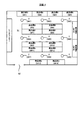
- FIG. 2 is a sketch showing an example of a store 5 in which the store monitoring system of the present embodiment is adopted.
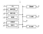
- FIG. 3 is a block diagram showing the configuration of the store monitoring server of the present embodiment.
- FIG. 4 is a block diagram showing the configuration of the image pickup apparatus of the present embodiment.
- FIG. 5 is a flowchart showing the flow of the image generation operation.
- FIG. 6 is a plan view showing an captured image captured by the imaging device.
- FIG. 7 is a plan view showing a front shelf image generated from the captured image shown in FIG.
- FIG. 8A is a plan view showing a captured image in which a plurality of reference points are arranged, and FIG.
- FIG. 8B is a plurality of front shelf images generated from the captured image shown in FIG. 8A. It is a top view which shows together with the reference point of.
- FIG. 9 is a plan view showing a display device that displays a front shelf image and a teacher image together with a captured image.
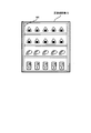
- FIG. 10 is a plan view showing a product shelf on which a plurality of marks are arranged.
- FIG. 11 is a plan view showing an captured image obtained by imaging the product shelves on which the plurality of marks are arranged as shown in FIG. 10, and
- FIG. 11B is a plan view showing the product shelves on which the plurality of marks are arranged. It is a plan view which shows.
- FIG. 12 is a plan view showing another example of a product shelf in which a plurality of marks are arranged.
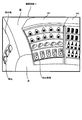
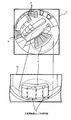
- FIG. 13 is a plan view showing an image captured by a camera including a circumferential fisheye lens and a panoramic image generated by developing the captured image in a plane.
- FIG. 14 is a block diagram showing another example of the configuration of the store monitoring server of the present embodiment.
- FIG. 1 is a block diagram showing an overall configuration of the store monitoring system 4 of the present embodiment.
- the store monitoring system 4 includes a store monitoring server 1 and a plurality of imaging devices 2.
- the store monitoring system 4 may include a single imaging device 2.
- the store monitoring server 1 and the plurality of image pickup devices 2 can communicate with each other via the network network 3.
- the network network 3 may include a wired network or a wireless network.
- FIG. 2 An example of a store 5 in which such a store monitoring system 4 is adopted is shown in FIG. 2 as a sketch of the store 5.
- the store 5 includes a shopping space 51 in which a plurality of product shelves 6 are installed.
- FIG. 2 shows a shopping space 51 in which 16 product shelves 6 (specifically, product shelves 6 # 1 to 6 # 16) are installed.
- the number of product shelves 6 is not limited to 16.
- 17 or more product shelves 6 may be installed, 15 or less product shelves 6 may be installed, or a single product shelf 6 may be installed. Good.
- the customer can enter the shopping space 51 from the outside of the store 5 through the entrance 52 of the store 5.
- FIG. 2 shows an example in which the shopping space 51 is arranged inside the store 5. However, at least a part of the shopping space 51 may be arranged outside the store 5 (for example, the eaves of the store 5).
- the image pickup device 2 is arranged at a position where the shopping space 51 can be imaged (for example, inside and / or outside of the store 5).
- FIG. 2 shows an example in which nine image pickup devices 2 (specifically, image pickup devices 2 # 1 to image pickup devices 2 # 9) are arranged in the store 5.
- the image pickup device 2 captures at least one product shelf 6 installed in the shopping space 51 to generate an image 71 showing the state of at least one product shelf 6.
- the image pickup device 2 transmits (in other words, outputs) the generated captured image 71 to the store monitoring server 1 via the network network 3.
- the store monitoring server 1 receives (in other words, acquires) the captured image 71 transmitted from the imaging device 2.
- the store monitoring server 1 monitors the product shelf 6 of the store 5 by using the acquired captured image 71.
- the store monitoring server 1 is a front shelf image 72 obtained from the captured image 71 when the product shelf 6 reflected in the captured image 71 and the product shelf 6 to be monitored is imaged from the front. Performs an image generation operation to generate. Further, the store monitoring server 1 uses the generated front shelf image 72 to perform a monitoring operation for monitoring the product shelf 6.
- the store monitoring server 1 may be arranged inside the store 5 or outside the store 5.
- each device that is, the store monitoring server 1 and the imaging device 2 constituting such a store monitoring system 4 will be described in order.
- FIG. 3 is a block diagram showing the configuration of the store monitoring server 1 of the present embodiment.
- the store monitoring server 1 includes a CPU (Central Processing Unit) 11, a storage device 12, a communication device 13, an input device 14, and a display device 15.
- the CPU 11, the storage device 12, the communication device 13, the input device 14, and the display device 15 are connected via the data bus 16.
- the CPU 11 reads a computer program.
- the CPU 11 may read a computer program stored in the storage device 12.
- the CPU 11 may read a computer program stored in a computer-readable recording medium using a recording medium reading device (not shown).
- the CPU 11 may acquire a computer program from a device (not shown) arranged outside the store monitoring server 1 via the communication device 13 (that is, it may be downloaded or read).
- the CPU 11 executes the read computer program.
- a logical functional block for executing the operations to be performed by the store monitoring server 1 (for example, the image generation operation and the monitoring operation described above) is realized in the CPU 11. That is, the CPU 11 can function as a controller for realizing a logical functional block for executing the operation to be performed by the store monitoring server 1.
- FIG. 3 shows an example of a logical functional block realized in the CPU 11 in order to execute the operation to be performed by the store monitoring server 1.
- an image acquisition unit 111, an image generation unit 112, and a monitoring unit 113 are realized in the CPU 11.
- the image acquisition unit 111 sequentially acquires the captured image 71 from the image capturing device 2 via the communication device 13 each time the camera 21 images the product shelf 6 (that is, each time a new captured image 71 is generated).
- the image generation unit 112 generates the front shelf image 72 by executing the above-mentioned image generation operation each time the camera 21 images the product shelf 6 (that is, each time a new captured image 71 is generated).
- the monitoring unit 113 executes the above-mentioned monitoring operation.
- the storage device 12 can store desired data.
- the storage device 12 may temporarily store a computer program executed by the CPU 11.
- the storage device 12 may temporarily store data temporarily used by the CPU 11 when the CPU 11 is executing a computer program.
- the storage device 12 may store data stored by the store monitoring server 1 for a long period of time.
- the storage device 12 stores an image DB (DataBase) 121 that stores (that is, records, stores, or stores) the front shelf image 72 generated by the image generation operation. .. That is, each time the camera 21 images the product shelf 6 (that is, each time a new captured image 71 is generated), the storage device 12 sequentially stores the front shelf image 72 generated from the captured image 71 in the image DB 121.
- the storage device 12 may include at least one of a RAM (Random Access Memory), a ROM (Read Only Memory), a hard disk device, a magneto-optical disk device, an SSD (Solid State Drive), and a disk array device. Good.
- the communication device 13 can communicate with a plurality of image pickup devices 2 via the network network 3.
- the communication device 13 can receive the captured images 71 captured by each of the plurality of imaging devices 2 from each of the plurality of imaging devices 2 via the network network 3.
- the input device 14 is a device that receives an input operation from a user of the store monitoring server 1 (for example, an administrator of the store 5).
- the input device 14 may include, for example, a user-operable operating device.
- the input device 14 may include, for example, at least one of a keyboard, a mouse, and a touch panel as an example of the operating device.
- the display device 15 is an output device (that is, a display) capable of displaying a desired image.
- FIG. 4 is a block diagram showing the configuration of the image pickup apparatus 2 of the present embodiment.
- the image pickup device 2 includes a camera 21 and a communication device 22.
- the camera 21 and the communication device 22 may be connected via the data bus 23.
- the camera 21 is a device that generates an image 71 showing the state of at least one product shelf 6 by photographing at least one product shelf 6.
- the camera 21 is a store so that at least one product shelf 6 to be imaged by the camera 21 is located (that is, included) within the imaging range (in other words, the imaging angle of view) of the camera 21. It is arranged in 5. That is, the camera 21 is arranged in the store 5 so as to image at least one product shelf 6 to be imaged by the camera 21.
- the imaging range of the camera 21 is fixed in principle. That is, it is preferable that at least one product shelf 6 to be imaged by the camera 21 does not change in principle. It is preferable that the camera 21 continues to image the same product shelf 6.
- the camera 21 continues to image the product shelf 6 at a predetermined imaging rate. For example, when a predetermined imaging rate is set to 1 fps (Flame Per Sec), the camera 21 generates a product shelf 6 once per second so that one captured image 71 is generated per second. The operation of imaging the image is repeated.
- a predetermined imaging rate is set to 1 fps (Flame Per Sec)
- the camera 21 generates a product shelf 6 once per second so that one captured image 71 is generated per second. The operation of imaging the image is repeated.
- the camera 21 may be a camera including a wide-angle lens.
- the camera 21 may be a fisheye camera including a circumferential fisheye lens.
- the camera 21 may be a fisheye camera including a diagonal fisheye lens.
- the camera 21 may be a camera that includes other types of lenses.
- the communication device 22 can communicate with the store monitoring server 1 via the network network 3.
- the communication device 22 can transmit the captured image 71 captured by the camera 21 to the store monitoring server 1 via the network network 3.
- each of the plurality of image pickup devices 2 is provided with the communication device 22.
- at least two of the plurality of image pickup devices 2 may transmit the captured image 71 to the store monitoring server 1 using the shared communication device 22.
- at least two cameras 21 provided by at least two imaging devices 2 using the shared communication device 22 and the shared communication device 22 may be connected via a data bus (not shown).
- the store monitoring system 4 executes the monitoring operation and the image generation operation. Therefore, in the following, the monitoring operation and the image generation operation will be described in order.
- the store monitoring server 1 mainly executes each of the above-described operations together with the plurality of image pickup devices 2. Therefore, in the present embodiment, the operation executed by the store monitoring system 4 may be executed by the store monitoring server 1.
- the monitoring unit 113 may execute an operation of monitoring whether or not an abnormality has occurred in the product shelf 6 reflected in the front shelf image 72 based on the front shelf image 72. ..
- the abnormality that occurs on the product shelf 6 may include an abnormality that the number of products displayed on the product shelf 6 is below the lower limit.
- the abnormality that occurs on the product shelf 6 may include an abnormality that the products displayed on the product shelf 6 are insufficient.
- the abnormality that occurs on the product shelf 6 may include an abnormality that the size of the empty space in which the product is not displayed on the product shelf 6 becomes a predetermined size or more.
- the abnormality that occurs on the product shelf 6 may include an abnormality that a product different from the product to be displayed on the product shelf 6 is displayed on the product shelf 6.
- the monitoring unit 113 executes an operation of notifying the user of the store monitoring system 4 (for example, the manager of the store 5 as described above) that an abnormality has occurred in the product shelf 6.
- the monitoring unit 113 may control the display device 15 so that an alarm image indicating that an abnormality has occurred in the product shelf 6 is displayed on the display device 15.
- the monitoring unit 113 controls the user terminal so that an alarm image indicating that an abnormality has occurred in the product shelf 6 is displayed on the user terminal (for example, a mobile terminal such as a smartphone) owned by the user.
- the user terminal for example, a mobile terminal such as a smartphone
- the storage device 12 captures the front shelf image 72 generated from the captured image 71 each time the camera 21 images the product shelf 6 (that is, each time a new captured image 71 is generated). It is accumulating sequentially in.
- the state of the product shelf 6 reflected in the front shelf image 72 has not changed or has not changed so much, the product shelf 6 in substantially the same state is reflected in the image DB 121.
- a plurality of front shelf images 72 are accumulated.
- a plurality of front shelf images in which the product shelves 6 in substantially the same state are reflected.
- the need for all 72 to be accumulated is relatively low.
- the state of the product shelf 6 reflected in the front shelf image 72 has changed relatively significantly, a plurality of fronts generated from the plurality of captured images 71 acquired at relatively short time intervals. If the shelf images 72 are accumulated, the store monitoring system 4 can appropriately monitor how the state of the product shelves 6 has changed. Therefore, the storage device 12 is based on the amount of change in the state of the product shelf 6 reflected in the front shelf image 72 per unit time, and the storage device 12 stores the front shelf image 72 in the image DB 121 per unit time. You may change the number.
- the storage device 12 is a front shelf in which the storage device 12 accumulates in the image DB 121 per unit time as the amount of change in the state of the product shelf 6 reflected in the front shelf image 72 decreases per unit time.
- the number of front shelf images 72 that the storage device 12 accumulates in the image DB 121 per unit time may be changed so that the number of images 72 is reduced.
- the number of front shelf images 72 that the storage device 12 accumulates in the image DB 121 per unit time increases.
- the number of front shelf images 72 that the storage device 12 accumulates in the image DB 121 per unit time may be changed so as to increase the number.
- the storage device 12 when the amount of change in the state of the product shelf 6 per unit time is the first amount, the storage device 12 accumulates the first number of front shelf images 72 per unit time, and stores the product shelf 6 When the amount of change per unit time of the state is a second amount larger than the first amount, a second number of front shelf images 72 that are larger than the first number per unit time are accumulated. You may. As a result, the pressure on the storage capacity of the storage device 12 due to the storage of substantially the same plurality of front shelf images 72 is suppressed, and the product shelf 6 whose state changes relatively significantly is appropriately monitored. Is possible.
- the amount of change in the state of the product shelf 6 reflected in the front shelf image 72 per unit time may be calculated by the monitoring unit 113.
- the monitoring unit 113 stores the front shelf image 72 that the storage device 12 accumulates in the image DB 121 per unit time based on the amount of change in the state of the product shelf 6 reflected in the front shelf image 72 per unit time.
- the storage device 12 may be controlled so as to change the number of.
- FIG. 5 is a flowchart showing the flow of the image generation operation.
- the image acquisition unit 111 acquires the captured image 71 from the image pickup device 2 via the communication device 13 (step S11).
- the camera 21 of the imaging device 2 continues to image the product shelf 6 at a predetermined imaging rate. Therefore, the image acquisition unit 111 sequentially acquires the captured image 71 from the imaging device 2 each time the camera 21 images the product shelf 6 (that is, each time a new captured image 71 is generated). That is, each time the camera 21 images the product shelf 6 (that is, each time a new captured image 71 is generated), the store monitoring server 1 sequentially starts the image generation operation shown in FIG.
- the store monitoring server 1 executes an image generation operation on a part of the plurality of captured images 71 received from the image pickup device 2, the other part of the plurality of captured images 71 received from the image pickup device 2 is performed. It is not necessary to execute the image generation operation on the server. In this case, the processing load required for the image generation operation is reduced as compared with the case where the image generation operation is executed for all of the plurality of captured images 71 received from the image pickup device 2.
- the image generation unit 112 After that, the image generation unit 112 generates the front shelf image 72 from the captured image 71 acquired in step S11 (step S12).
- the reason for generating the front shelf image 72 from the captured image 71 will be described with reference to FIG.
- FIG. 6 is a plan view showing the captured image 71.
- the camera 21 of the image pickup device 2 installed in the store 5 It is usually difficult for the camera 21 of the image pickup device 2 installed in the store 5 to image the product shelf 6 to be imaged by the camera 21 from the front. Therefore, usually, the camera 21 is arranged on the ceiling of the store 5, and often takes an image of the product shelf 6 from above or diagonally above the product shelf 6. In this case, since the camera 21 does not image the product shelf 6 from the front, the product shelf 6 may be distorted and reflected in the captured image 71 as shown in FIG.
- the imaging range of the camera 21 may include an object different from the product shelf 6 to be imaged by the camera 21.
- the captured image 71 captured by the camera 21 may reflect an object different from the product shelf 6 to be captured by the camera 21.
- FIG. 6 shows an image 71 captured by a camera 21 that should image the product shelf 6 # 1 (for example, the camera 21 of the image device 2 # 1 in FIG. 2 (hereinafter referred to as “camera # 21”)). Shown. As shown in FIG. 6, not only the product shelves 6 # 1 but also the product shelves 6 # 2 that the camera 21 # 1 does not need to image are reflected in the captured image 71. As shown in FIG.
- the captured image 71 includes not only the product shelves 6 # 1 but also objects other than the product shelves 6 (for example, the floor of the store 5, the wall of the store 5, the products sold in the store 5 and the products sold in the store 5. At least one of the notices in store 5) is also reflected. It can be said that such an object different from the product shelf 6 to be imaged by the camera 21 is an object unnecessary for monitoring the product shelf 6.
- the captured image 71 is not always an image suitable for monitoring the product shelf 6. Therefore, in the present embodiment, the image generation unit 112 generates a front shelf image 72 that is more suitable for monitoring the product shelf 6 than the captured image 71 from the captured image 71. As a result, the product shelf 6 can be monitored more appropriately by the monitoring operation described later, as compared with the case where the front shelf image 72 is not generated.
- the front shelf image 72 generated from the captured image 71 shown in FIG. 6 is shown in FIG. 7.
- the product shelf 6 reflected in the front shelf image 72 has less distortion than the product shelf 6 reflected in the captured image 71.
- the product shelf 6 reflected in the front shelf image 72 is not distorted.
- the front shelf image 72 does not reflect an object that is reflected in the captured image 71 and is unnecessary for monitoring the product shelf 6.
- the store monitoring server 1 executes a monitoring operation using the front shelf image 72.
- the image generation unit 112 extracts an image portion (that is, a shelf image) in which the product shelf 6 to be included in the front shelf image 72 is reflected from the captured image 71. .. In other words, the image generation unit 112 excludes the remaining image portion other than the image portion in which the product shelf 6 to be included in the front shelf image 72 is reflected from the captured image 71.
- the image generation unit 112 excludes an image portion (that is, a non-shelf image portion) in which the product shelf 6 to be included in the front shelf image 72 is not reflected from the captured image 71.
- the image generation unit 112 may extract the image portion in the thick dotted line surrounding the product shelf 6 # 1 as an extracted image. That is, the image generation unit 112 may exclude the image portion outside the thick dotted line surrounding the product shelf 6 # 1.
- the image generation unit 112 corrects the distortion of the extracted image corresponding to the image of the extracted product shelf 6. Specifically, the image generation unit 112 deforms the extracted image so that the distortion of the extracted image is reduced or eliminated. The image generation unit 112 deforms the extracted image so that the distortion of the product shelf 6 reflected in the extracted image is reduced or eliminated. As a result, the distortion-corrected extracted image is used as the front shelf image 72.
- the image generation unit 112 may extract the image portion in which the product shelf 6 to be included in the front shelf image 72 is reflected from the image 71 with the distortion corrected after the distortion of the captured image 71 is corrected. That is, the image generation unit 112 may remove the image portion in which the product shelf 6 to be included in the front shelf image 72 is not reflected from the image 71 after correcting the distortion of the captured image 71. .. Alternatively, the image generation unit 112 simultaneously or in parallel performs a process of correcting the distortion of the captured image 71 and a process of extracting an image portion in which the product shelf 6 to be included in the front shelf image 72 is reflected from the captured image 71. You may do it.
- the image generation unit 112 simultaneously or in parallel performs the process of correcting the distortion of the captured image 71 and the process of removing the image portion in which the product shelf 6 to be included in the front shelf image 72 is not reflected from the captured image 71. You may execute it. In any case, the front shelf image 72 is still generated from the captured image 71.
- the front shelf image 72 generated in step S12 is stored in the image DB 121 stored in the storage device 12 (step S13).
- the store monitoring server 1 sequentially starts the image generation operation shown in FIG. .. Therefore, the image generation unit 112 sequentially generates the front shelf image 72 each time the camera 21 images the product shelf 6 (that is, each time a new captured image 71 is generated). Therefore, the storage device 12 also sequentially stores the front shelf image 72 in the image DB 121 each time the image generation unit 112 generates the front shelf image 72.
- the front shelf image 72 stored in the storage device 12 is used, for example, to monitor the product shelf 6 in a monitoring operation described later.
- the image generation unit 112 uses at least one of the first image generation method, the second image generation method, and the third image generation method to obtain the front shelf image 72 from the captured image 71.
- the first image generation method, the second image generation method, and the third image generation method are methods for setting the processing content (that is, the processing content for generating the front shelf image 72 from the captured image 71). Are different from each other in that they are different. Therefore, in the following, the first image generation method to the third image generation method will be described in order.
- An operation for setting the processing content of the image generation method (for example, an operation of setting the processing content of the image generation method based on a user setting operation described later, and a processing content of the image generation method based on the mark 91 described later). Or the operation of setting the processing content of the image generation method based on the teacher image 73) may be performed before the start of operation of the store monitoring system 4.
- the operation for setting the processing content of the image generation method may be performed after the operation of the store monitoring system 4 is started.
- the image generation unit 112 may generate the front shelf image 72 according to the set processing content. That is, it is sufficient that the operation for setting the image generation method is performed at least once.
- the operation for setting the image generation method may be performed again.
- the processing content of the image generation method is set (in other words, changed, adjusted, or updated) so that a more appropriate front shelf image 72 is generated.
- the first image generation method is an image generation method in which the processing content is set based on the instruction of the user of the store monitoring system 4 (for example, as described above, the manager of the store 5). Specifically, the user inputs a setting operation for setting the processing content of the first image generation method using the input device 14.
- the image generation unit 112 sets the processing content of the first image generation method based on the content of the setting operation performed by the user using the input device 14. In this case, it can be said that the image generation unit 112 generates the front shelf image 72 from the captured image 71 based on the content of the setting operation performed by the user using the input device 14.
- the image generation unit 112 may first control the display device 15 so as to display the captured image 71.
- the captured image 71 is displayed on the display device 15.
- the user can perform a setting operation for setting the processing content of the first image generation method while referring to the captured image 71 displayed on the display device 15. Therefore, as compared with the case where the captured image 71 is not displayed, the user can easily set the processing content of the first image generation method.
- the setting operation for setting the processing content of the first image generation method is a plurality of reference points on the captured image 71 displayed on the display device 15. It may include an operation of arranging 81.
- the image generation unit 112 may control the display device 15 so as to display the plurality of arranged reference points 81 together with the captured image 71. Good.
- the user has a plurality of reference points 81 arranged on the captured image 71 on the captured image 71 so as to be arranged in a predetermined arrangement pattern on the front shelf image 72 generated from the captured image 71.
- the reference point 81 of is arranged. That is, when the front shelf image 72 is generated from the captured image 71 in a situation where a plurality of reference points 81 are arranged on each of the plurality of pixels in the captured image 71, the user responds in the front shelf image 72.
- a plurality of reference points 81 are arranged on the captured image 71 so that the plurality of pixels (that is, a plurality of pixels in which the plurality of reference points 81 are arranged respectively) are arranged in a predetermined arrangement pattern.
- the user places a plurality of reference points 81 arranged in a predetermined arrangement pattern on the distortion-corrected front shelf image 72 at corresponding positions on the distortion-corrected captured image 71 (ie, that is).
- a plurality of reference points 81 are arranged in the front shelf image 72 (a plurality of pixels corresponding to a plurality of pixels arranged respectively).
- FIG. 8A shows a captured image 71 in which a plurality of reference points 81 are arranged
- FIG. 8B shows a front shelf image generated from the captured image 71 shown in FIG. 8A.
- 72 is shown with a plurality of reference points 81.
- the user has a plurality of reference points 81 arranged on the captured image 71 in a matrix shape (that is, 5 rows ⁇ 5 columns) on the front shelf image 72.
- a plurality of reference points 81 are arranged on the captured image 71 so as to be arranged in an array pattern (in a grid pattern). That is, in the examples shown in FIGS.
- the user can see from the captured image 71 in a situation where a plurality of reference points 81 are arranged on a plurality of pixels in the plurality of captured images 71.
- a plurality of reference points are arranged on the captured image 71 so that the corresponding plurality of pixels in the front shelf image 72 are arranged in a matrix-like arrangement pattern of 5 rows ⁇ 5 columns.
- 81 is arranged.
- the user places a plurality of reference points 81 arranged in a matrix-like arrangement pattern of 5 rows ⁇ 5 columns on the front shelf image 72 at corresponding positions on the captured image 71 where distortion has not yet been corrected. Deploy.
- the image generation unit 112 may control the display device 15 so as to display a plurality of reference lines 82 connecting the plurality of arranged reference points 81 in a grid pattern together with the captured image 71.
- FIG. 8A since the captured image 71 is distorted, the plurality of reference lines 82 displayed together with the captured image 71 do not necessarily form a grid that intersects regularly or periodically. Not exclusively.
- FIG. 8A since the captured image 71 is distorted, the plurality of reference lines 82 displayed together with the captured image 71 do not necessarily form a grid that intersects regularly or periodically. Not exclusively.
- FIG. 8A since the captured image 71 is distorted, the plurality of reference lines 82 displayed together with the captured image 71 do not necessarily form a grid that intersects regularly or periodically. Not exclusively.
- FIG. 8A since the captured image 71 is distorted, the plurality of reference lines 82 displayed together with the captured image 71 do not necessarily form a grid that intersects regularly or periodically. Not exclusively.
- FIG. 8A since the captured
- the plurality of reference lines 82 form a grid that intersects regularly or periodically in the front shelf image 72.
- the user forms a grid in which the plurality of reference lines 82 regularly or periodically intersect in the front shelf image 72 (that is, they are arranged in a predetermined arrangement pattern) on the captured image 71.
- a plurality of reference points 81 may be arranged.
- the image generation unit 112 arranges the plurality of reference points 81 in the captured image 71 and the original arrangement pattern of the plurality of reference points 81.
- the processing content of the first image generation method is set based on (in the example shown in FIGS. 8A and 8B, a matrix-like array pattern).
- the image generation unit 112 describes the processing content for deforming the captured image 71 so that the plurality of reference points 81 arranged on the captured image 71 are arranged in a predetermined arrangement pattern in the first image generation method. It may be set as a processing content.
- the image generation unit 112 takes an image so that the plurality of reference lines 82 arranged on the captured image 71 are arranged in a predetermined arrangement pattern.
- the processing content for deforming the image 71 may be set as the processing content of the first image generation method.
- the image generation unit 112 sets the processing content of the first image generation method for each product shelf 6. This is because when a plurality of different product shelves 6 are imaged by a plurality of different cameras 21, the distortion of the product shelves 6 reflected in the captured image 71 is the positional relationship between the product shelves 6 and the cameras 21. This is because it changes according to. Further, even when a plurality of different product shelves 6 are imaged by a single camera 21, the product shelves 6 are reflected at different positions in the captured image 71. This is because the distortion of is changed according to the position where the product shelf 6 is reflected in the captured image 71. For example, in the example shown in FIG.
- the image generation unit 112 corresponds to the processing content of the first image generation method for generating the front shelf image 72 corresponding to the product shelf 6 # 1 and the product shelf 6 # 2.
- the image generation unit 112 displays the front shelf image 72 generated from the captured image 71 displayed on the display device 15 together with the captured image 71.
- the display device 15 may be controlled so as to display.
- the image generation unit 112 may regenerate the front shelf image 72 based on the latest processing content set each time the processing content of the first image generation method is set.
- the display device 15 may display the latest front shelf image 72 that has been regenerated each time the image generation unit 112 regenerates the front shelf image 72.
- the user refers to the front shelf image 72 generated by using the first image generation method whose processing content is set by the user's setting operation at the present time, and the processing content of the first image generation method. You can perform setting operations to set. Therefore, the user can appropriately perform the setting operation for setting the processing content of the first image generation method so that the front shelf image 72 becomes an appropriate image.
- the image generation unit 112 actually captures the product shelf 6 reflected in the captured image 71 displayed on the display device 15 from the front.
- the display device 15 may be controlled so that the teacher image 73 obtained by the above is displayed side by side with the front shelf image 72.
- the teacher image 73 is typically an image obtained by actually capturing the product shelf 6 from the front using a camera different from the camera 21 of the image pickup device 2.
- the teacher image 73 may typically be an image obtained by actually capturing the product shelf 6 from the front using the camera 21 of the image pickup device 2.
- the user can perform a setting operation for setting the processing content of the first image generation method while comparing the front shelf image 72 and the teacher image 73. Therefore, the user can appropriately perform the setting operation for setting the processing content of the first image generation method so that the front shelf image 72 approaches or matches the teacher image 73.
- the teacher image 73 may be an image obtained by actually capturing an image of the product shelf 6 having the same specifications as the product shelf 6 reflected in the captured image 71 displayed on the display device 15 from the front. Good.
- the teacher image 73 may be an image obtained by actually capturing a product shelf 6 having the same size as the product shelf 6 reflected in the captured image 71 displayed on the display device 15 from the front.
- the teacher image 73 may be an image obtained by actually capturing an image of the product shelf 6 having the same shape as the product shelf 6 reflected in the captured image 71 displayed on the display device 15 from the front.
- the teacher image 73 can be used even when it is difficult to image the actual product shelf 6 from the front. Even in this case, the user can appropriately perform the setting operation for setting the processing content of the first image generation method so that the front shelf image 72 approaches or matches the teacher image 73.
- the processing content of the second image generation method is automatically set based on the captured image 71 (that is, without requiring a user setting operation for setting the processing content of the second image generation method). It is an image generation method to be performed.
- the plurality of marks 91 are arranged on the product shelf 6 so as to be arranged in a predetermined arrangement pattern when the product shelf 6 is viewed from the front.
- the plurality of marks 91 are arranged in a matrix-like (that is, grid-like) arrangement pattern of 5 rows ⁇ 5 columns when the product shelf 6 is viewed from the front. Is placed in.
- the captured image 71 of the product shelf 6 on which such a plurality of marks 91 are arranged is shown in FIG. 11 (a).
- FIG. 11A in addition to the product shelf 6, a plurality of marks 91 arranged on the product shelf 6 are also reflected in the captured image 71.
- the plurality of marks 91 are not arranged in a predetermined arrangement pattern due to the distortion of the captured image 71 (that is, the distortion of the product shelf 6 in the captured image 71). ..
- the image generation unit 112 calculates the arrangement positions of the plurality of marks 91 in the captured image 71, and the calculated arrangement positions of the plurality of marks 91 and the original arrangement pattern of the plurality of marks 91 (in FIG. 10).
- the processing content of the second image generation method is set based on the matrix-like array pattern).
- the image generation unit 112 deforms the captured image 71 so that a plurality of marks 91 reflected in the captured image 71 are arranged in a predetermined arrangement pattern.
- the content may be generated as the processing content of the second image generation method. For example, as shown in FIG.
- the image generation unit 112 fronts from the captured image 71 so that a plurality of marks 91 are arranged in a predetermined arrangement pattern in the front shelf image 72 generated from the captured image 71.
- the processing content for generating the shelf image 72 may be generated as the processing content of the second image generation method. In this case, it can be said that the image generation unit 112 substantially generates the front shelf image 72 from the captured image 71 based on the mark 91.
- the arrangement positions and numbers of the plurality of marks 91 shown in FIG. 10 are merely examples. Therefore, the product shelves 6 may be arranged so that an arbitrary number of marks 91 are arranged in an arbitrary arrangement pattern. For example, as shown in FIG. 12, a plurality of marks 91 connecting the outer edges of the product shelves 6 (particularly, the outer edges of the shelf portion to be included in the front shelf image 72) may be arranged on the product shelves 6. Also in this case, the image generation unit 112 calculates the arrangement positions of the plurality of marks 91 in the captured image 71, and is based on the calculated arrangement positions of the plurality of marks 91 and the original arrangement pattern of the plurality of marks 91. Therefore, the processing content of the second image generation method can be set.
- the image generation unit 112 may use a straight line connecting the two adjacent marks 91 or a line that can be expressed by a predetermined mathematical expression (for example,).
- the processing content of the second image generation method may be set on the assumption that the virtual mark 91 exists on the line corresponding to the reference line 82 described above.
- the store monitoring server 1 that generates the front shelf image 72 by using the second image generation method does not have to include the input device 14 that receives the input of the user's setting operation (see FIG. 14 described later). ..
- the store monitoring server 1 that generates the front shelf image 72 using the second image generation method has an image that can be referred to when the user inputs a setting operation (for example, as shown in FIG. 9, the captured image 71, the front surface).
- the display device 15 for displaying (at least one of the shelf image 72 and the teacher image 73) may not be provided (see FIG. 14 described later).
- the processing content is automatically set based on the captured image 71 and the teacher image 73 (see FIG. 9) (that is, the user setting operation for setting the processing content of the image generation method). It is an image generation method that is set (without needing it).
- the image generation unit 112 extracts the feature points of the product shelf 6 reflected in the captured image 71 based on the captured image 71. Further, the image generation unit 112 extracts the feature points of the product shelf 6 reflected in the teacher image 73 based on the teacher image 73.
- the image generation unit 112 deforms the captured image 71 so that the feature points of the product shelf 6 in the captured image 71 approach or match the feature points of the product shelf 6 in the teacher image 73. May be generated as the processing content of the second image generation method. In this case, it can be said that the image generation unit 112 substantially generates the front shelf image 72 from the captured image 71 based on the teacher image 73.
- the image generation unit 112 may specify the shape and size of the product shelf 6 in the captured image 71 based on the feature points of the product shelf 6 reflected in the captured image 71. Further, the image generation unit 112 may specify the shape and size of the product shelf 6 in the teacher image 73 based on the feature points of the product shelf 6 reflected in the teacher image 73. For example, the image generation unit 112 may specify the height of the product shelf 6, the width of the product shelf 6, and the distance between two adjacent shelf boards as the shape and size of the product shelf 6. After that, the image generation unit 112 deforms the captured image 71 so that the shape and size of the product shelf 6 in the captured image 71 approaches or matches the shape and size of the product shelf 6 in the teacher image 73.
- the processing content may be generated as the processing content of the second image generation method. That is, the image generation unit 112 makes the shape and size of the product shelf 6 in the front shelf image 72 generated from the captured image 71 approach or match the shape and size of the product shelf 6 in the teacher image 73.
- the processing content for generating the front shelf image 72 from the captured image 71 may be generated as the processing content of the second image generation method.
- the third image generation method does not necessarily require a user setting operation for setting the processing content of the image generation method, as in the second image generation method. Therefore, the store monitoring server 1 that generates the front shelf image 72 by using the third image generation method does not have to include at least one of the input device 14 and the display device 15 (see FIG. 14 described later).
- the store monitoring system 4 of the present embodiment can appropriately monitor the product shelves 6 of the store 5.
- the store monitoring system 4 from the captured image 71 in which an object unnecessary for monitoring the product shelf 6 is reflected, the front shelf image 72 in which an object unnecessary for monitoring the product shelf 6 is not reflected. Can be generated. Therefore, the store monitoring system 4 can appropriately monitor the product shelves 6 to be monitored without being adversely affected by objects unnecessary for monitoring the product shelves 6.
- the store monitoring system 4 can appropriately set the processing content of the first image generation method based on the user's setting operation. Therefore, the store monitoring system 4 can generate the front shelf image 71 while considering the user's knowledge.
- the store monitoring system 4 can automatically set the processing content of the second or third image generation method without requiring the user's setting operation. Therefore, the store monitoring system 4 can reduce the burden on the user required to set the processing content of the image generation method.
- the process content of the image generation method is automatically set. Therefore, it is sufficient for the user to place the mark 91 on the product shelf 6.
- the mark 91 is arranged on the product shelf 6 from the beginning, the user does not even have to arrange the mark 91 on the product shelf 6.
- the teacher image 73 can be prepared, the user does not even have to arrange the mark 91 on the product shelf 6. Therefore, the store monitoring system 4 can further reduce the burden on the user required to set the processing content of the image generation method.
- the captured image 71 captured by the camera 21 is included in the imaging range of 360 degrees around as shown in the upper part of FIG.
- the scene is an image projected in a circular area.
- the image generation unit 112 develops the captured image 71 shown in the upper part of FIG. 13 into the panoramic image 74 shown in the lower part of FIG. 13 (that is, plane development) in order to generate the front shelf image 72 from the captured image 71. ) May.
- the product shelf 6 can be reflected in the panoramic image 74 generated by the plane development of the captured image 71 in a state where the distortion is relatively small. There is sex.
- the image generation unit 112 may extract an image portion in which the product shelf 6 with relatively little distortion is reflected from the panoramic image 74.
- the extracted image portion (that is, the image portion in which the product shelf 6 with relatively little distortion is reflected) may be used as the front shelf image 72.
- the store monitoring system 4 includes a store monitoring server 1 including a monitoring unit 113.
- the store monitoring system 4 may include a store monitoring server 1a that does not include the monitoring unit 113 shown in FIG. 14 instead of the store monitoring server 1.
- an external device of the store monitoring server 1a may include the monitoring unit 113.
- the monitoring unit 113 provided in the external device of the store monitoring server 1a may execute the monitoring operation by using the front shelf image 72 generated by the store monitoring server 1a.
- the store monitoring system 4 includes a store monitoring server 1 including a storage device 12 in which the image DB 121 is stored.
- the store monitoring system system SYS may include a storage device 12 that does not store the image DB 121 shown in FIG. 14 instead of the store monitoring server 1.
- the image DB 121 may be stored in an external device of the store monitoring server 1a.
- the invention of the present application is not limited to the above embodiment.
- the invention of the present application can be appropriately modified within the scope of claims and within the scope not contrary to the gist or idea of the invention that can be read from the entire specification, and the store monitoring system, store monitoring device, store monitoring method, computer accompanied by such changes. Programs and recording media are also included in the technical idea of the present invention.
- monitoring server 11 CPU 111 Image acquisition unit 112 Image generation unit 113 Monitoring unit 12 Storage device 121 Image DB 13 Communication device 14 Input device 15 Display device 2 Imaging device 21 Camera 22 Communication device 4 Store monitoring system 71 Captured image 72 Front shelf image 81 Reference point 82 Reference line
Landscapes
- Engineering & Computer Science (AREA)
- Theoretical Computer Science (AREA)
- Physics & Mathematics (AREA)
- General Physics & Mathematics (AREA)
- Multimedia (AREA)
- Business, Economics & Management (AREA)
- Signal Processing (AREA)
- Accounting & Taxation (AREA)
- Finance (AREA)
- Computing Systems (AREA)
- Development Economics (AREA)
- Economics (AREA)
- Marketing (AREA)
- Strategic Management (AREA)
- General Business, Economics & Management (AREA)
- Management, Administration, Business Operations System, And Electronic Commerce (AREA)
- Closed-Circuit Television Systems (AREA)
- Display Racks (AREA)
- Geometry (AREA)
Priority Applications (2)
| Application Number | Priority Date | Filing Date | Title |
|---|---|---|---|
| US17/770,356 US20220358745A1 (en) | 2019-10-31 | 2020-10-28 | Store monitoring system, store monitoring apparatus, store monitoring method and recording medium |
| JP2021553648A JP7509151B2 (ja) | 2019-10-31 | 2020-10-28 | 店舗監視システム、店舗監視装置、店舗監視方法及び記録媒体 |
Applications Claiming Priority (2)
| Application Number | Priority Date | Filing Date | Title |
|---|---|---|---|
| JP2019-198268 | 2019-10-31 | ||
| JP2019198268 | 2019-10-31 |
Publications (1)
| Publication Number | Publication Date |
|---|---|
| WO2021085467A1 true WO2021085467A1 (ja) | 2021-05-06 |
Family
ID=75716010
Family Applications (1)
| Application Number | Title | Priority Date | Filing Date |
|---|---|---|---|
| PCT/JP2020/040412 Ceased WO2021085467A1 (ja) | 2019-10-31 | 2020-10-28 | 店舗監視システム、店舗監視装置、店舗監視方法及び記録媒体 |
Country Status (3)
| Country | Link |
|---|---|
| US (1) | US20220358745A1 (https=) |
| JP (1) | JP7509151B2 (https=) |
| WO (1) | WO2021085467A1 (https=) |
Cited By (1)
| Publication number | Priority date | Publication date | Assignee | Title |
|---|---|---|---|---|
| CN114640797A (zh) * | 2021-11-03 | 2022-06-17 | 深圳友朋智能商业科技有限公司 | 同步优化商品轨迹的订单生成方法、装置及智能售货机 |
Families Citing this family (1)
| Publication number | Priority date | Publication date | Assignee | Title |
|---|---|---|---|---|
| JP2023096810A (ja) * | 2021-12-27 | 2023-07-07 | 富士フイルムビジネスイノベーション株式会社 | 検知装置、検知システムおよび発光装置 |
Citations (5)
| Publication number | Priority date | Publication date | Assignee | Title |
|---|---|---|---|---|
| JP2006059038A (ja) * | 2004-08-18 | 2006-03-02 | Nomura Research Institute Ltd | フェイスアップ度評価システム及び評価プログラム |
| JP2015148956A (ja) * | 2014-02-06 | 2015-08-20 | 東芝テック株式会社 | 画像処理装置及び画像処理プログラム |
| JP2016099923A (ja) * | 2014-11-26 | 2016-05-30 | パナソニックIpマネジメント株式会社 | モニタリング装置、モニタリングシステムおよびモニタリング方法 |
| JP2019079322A (ja) * | 2017-10-25 | 2019-05-23 | 東芝テック株式会社 | 商品管理装置及び商品管理プログラム |
| JP2019159433A (ja) * | 2018-03-07 | 2019-09-19 | 株式会社マーケットヴィジョン | 画像認識システム |
Family Cites Families (2)
| Publication number | Priority date | Publication date | Assignee | Title |
|---|---|---|---|---|
| US10176452B2 (en) * | 2014-06-13 | 2019-01-08 | Conduent Business Services Llc | Store shelf imaging system and method |
| US11896144B1 (en) * | 2020-12-03 | 2024-02-13 | Amazon Technologies, Inc. | Determining inventory levels using rotatable counting devices and visual imagery |
-
2020
- 2020-10-28 WO PCT/JP2020/040412 patent/WO2021085467A1/ja not_active Ceased
- 2020-10-28 JP JP2021553648A patent/JP7509151B2/ja active Active
- 2020-10-28 US US17/770,356 patent/US20220358745A1/en not_active Abandoned
Patent Citations (5)
| Publication number | Priority date | Publication date | Assignee | Title |
|---|---|---|---|---|
| JP2006059038A (ja) * | 2004-08-18 | 2006-03-02 | Nomura Research Institute Ltd | フェイスアップ度評価システム及び評価プログラム |
| JP2015148956A (ja) * | 2014-02-06 | 2015-08-20 | 東芝テック株式会社 | 画像処理装置及び画像処理プログラム |
| JP2016099923A (ja) * | 2014-11-26 | 2016-05-30 | パナソニックIpマネジメント株式会社 | モニタリング装置、モニタリングシステムおよびモニタリング方法 |
| JP2019079322A (ja) * | 2017-10-25 | 2019-05-23 | 東芝テック株式会社 | 商品管理装置及び商品管理プログラム |
| JP2019159433A (ja) * | 2018-03-07 | 2019-09-19 | 株式会社マーケットヴィジョン | 画像認識システム |
Cited By (1)
| Publication number | Priority date | Publication date | Assignee | Title |
|---|---|---|---|---|
| CN114640797A (zh) * | 2021-11-03 | 2022-06-17 | 深圳友朋智能商业科技有限公司 | 同步优化商品轨迹的订单生成方法、装置及智能售货机 |
Also Published As
| Publication number | Publication date |
|---|---|
| JPWO2021085467A1 (https=) | 2021-05-06 |
| US20220358745A1 (en) | 2022-11-10 |
| JP7509151B2 (ja) | 2024-07-02 |
Similar Documents
| Publication | Publication Date | Title |
|---|---|---|
| JP5092459B2 (ja) | 遠隔指示システム及び遠隔指示システム用のプログラム | |
| CN104123113B (zh) | 一种移动终端及其多系统的分屏显示方法和装置 | |
| CN111295684A (zh) | 货架监视装置、货架监视方法及货架监视程序 | |
| CN104813654A (zh) | 图像校正系统、图像校正方法、以及计算机程序产品 | |
| JP2020010400A5 (https=) | ||
| CN108391147B (zh) | 显示控制装置和显示控制方法 | |
| JP2019087974A5 (https=) | ||
| WO2021085467A1 (ja) | 店舗監視システム、店舗監視装置、店舗監視方法及び記録媒体 | |
| WO2017107647A1 (zh) | 一种基于摄像机的监控方法、装置及系统 | |
| KR20160058498A (ko) | 멀티 디스플레이 장치의 레이아웃을 검출하는 장치 및 방법 | |
| JP5695597B2 (ja) | 画面表示装置及び画面表示システム | |
| JP6663229B2 (ja) | 情報処理装置、情報処理方法、およびプログラム | |
| CN108961424B (zh) | 虚拟信息处理方法、设备及存储介质 | |
| US20180068477A1 (en) | Display method, display device, and non-transitory computer-readable recording medium | |
| JP2021158559A5 (https=) | ||
| JP6623565B2 (ja) | 棚割情報生成装置、棚割情報生成システム、棚割情報生成方法、撮像装置、およびプログラム | |
| CN112328150B (zh) | 自动截图方法、装置以及设备、存储介质 | |
| JP2018125658A5 (https=) | ||
| CN113052763A (zh) | 一种融合图像生成方法、装置、计算机设备和存储介质 | |
| US20170155823A1 (en) | Method for operating camera device using user interface for providing split screen | |
| WO2021229753A1 (ja) | 商品特定装置、商品特定方法、およびプログラム | |
| JP7734281B2 (ja) | 物体検知システム、カメラ、及び物体検知方法 | |
| WO2021090755A1 (ja) | 管理装置、管理方法、およびプログラム | |
| JP5409154B2 (ja) | 撮影画像表示装置及び撮影画像表示方法 | |
| JPWO2021229753A5 (https=) |
Legal Events
| Date | Code | Title | Description |
|---|---|---|---|
| 121 | Ep: the epo has been informed by wipo that ep was designated in this application |
Ref document number: 20881958 Country of ref document: EP Kind code of ref document: A1 |
|
| ENP | Entry into the national phase |
Ref document number: 2021553648 Country of ref document: JP Kind code of ref document: A |
|
| NENP | Non-entry into the national phase |
Ref country code: DE |
|
| 122 | Ep: pct application non-entry in european phase |
Ref document number: 20881958 Country of ref document: EP Kind code of ref document: A1 |