WO2021079919A1 - Power conversion device - Google Patents
Power conversion device Download PDFInfo
- Publication number
- WO2021079919A1 WO2021079919A1 PCT/JP2020/039624 JP2020039624W WO2021079919A1 WO 2021079919 A1 WO2021079919 A1 WO 2021079919A1 JP 2020039624 W JP2020039624 W JP 2020039624W WO 2021079919 A1 WO2021079919 A1 WO 2021079919A1
- Authority
- WO
- WIPO (PCT)
- Prior art keywords
- power
- motor
- harmonic component
- voltage
- inverter circuit
- Prior art date
Links
- 238000006243 chemical reaction Methods 0.000 title claims abstract description 45
- 239000003990 capacitor Substances 0.000 claims description 23
- 230000008859 change Effects 0.000 claims description 10
- 238000000034 method Methods 0.000 description 21
- 238000001514 detection method Methods 0.000 description 14
- 238000010586 diagram Methods 0.000 description 11
- 230000006870 function Effects 0.000 description 7
- 230000004907 flux Effects 0.000 description 6
- 238000005516 engineering process Methods 0.000 description 5
- 230000009467 reduction Effects 0.000 description 5
- 230000001360 synchronised effect Effects 0.000 description 4
- 230000009194 climbing Effects 0.000 description 3
- 238000009499 grossing Methods 0.000 description 3
- 238000004804 winding Methods 0.000 description 3
- 238000012986 modification Methods 0.000 description 2
- 230000004048 modification Effects 0.000 description 2
- 230000000737 periodic effect Effects 0.000 description 2
- 229920006395 saturated elastomer Polymers 0.000 description 2
- 230000000694 effects Effects 0.000 description 1
- 238000004146 energy storage Methods 0.000 description 1
- 239000011159 matrix material Substances 0.000 description 1
- 230000010349 pulsation Effects 0.000 description 1
- 239000003507 refrigerant Substances 0.000 description 1
- 230000007704 transition Effects 0.000 description 1
Images


Classifications
-
- H—ELECTRICITY
- H02—GENERATION; CONVERSION OR DISTRIBUTION OF ELECTRIC POWER
- H02M—APPARATUS FOR CONVERSION BETWEEN AC AND AC, BETWEEN AC AND DC, OR BETWEEN DC AND DC, AND FOR USE WITH MAINS OR SIMILAR POWER SUPPLY SYSTEMS; CONVERSION OF DC OR AC INPUT POWER INTO SURGE OUTPUT POWER; CONTROL OR REGULATION THEREOF
- H02M1/00—Details of apparatus for conversion
- H02M1/12—Arrangements for reducing harmonics from ac input or output
-
- H—ELECTRICITY
- H02—GENERATION; CONVERSION OR DISTRIBUTION OF ELECTRIC POWER
- H02M—APPARATUS FOR CONVERSION BETWEEN AC AND AC, BETWEEN AC AND DC, OR BETWEEN DC AND DC, AND FOR USE WITH MAINS OR SIMILAR POWER SUPPLY SYSTEMS; CONVERSION OF DC OR AC INPUT POWER INTO SURGE OUTPUT POWER; CONTROL OR REGULATION THEREOF
- H02M7/00—Conversion of ac power input into dc power output; Conversion of dc power input into ac power output
- H02M7/42—Conversion of dc power input into ac power output without possibility of reversal
- H02M7/44—Conversion of dc power input into ac power output without possibility of reversal by static converters
- H02M7/48—Conversion of dc power input into ac power output without possibility of reversal by static converters using discharge tubes with control electrode or semiconductor devices with control electrode
- H02M7/53—Conversion of dc power input into ac power output without possibility of reversal by static converters using discharge tubes with control electrode or semiconductor devices with control electrode using devices of a triode or transistor type requiring continuous application of a control signal
- H02M7/537—Conversion of dc power input into ac power output without possibility of reversal by static converters using discharge tubes with control electrode or semiconductor devices with control electrode using devices of a triode or transistor type requiring continuous application of a control signal using semiconductor devices only, e.g. single switched pulse inverters
- H02M7/5387—Conversion of dc power input into ac power output without possibility of reversal by static converters using discharge tubes with control electrode or semiconductor devices with control electrode using devices of a triode or transistor type requiring continuous application of a control signal using semiconductor devices only, e.g. single switched pulse inverters in a bridge configuration
- H02M7/53871—Conversion of dc power input into ac power output without possibility of reversal by static converters using discharge tubes with control electrode or semiconductor devices with control electrode using devices of a triode or transistor type requiring continuous application of a control signal using semiconductor devices only, e.g. single switched pulse inverters in a bridge configuration with automatic control of output voltage or current
-
- H—ELECTRICITY
- H02—GENERATION; CONVERSION OR DISTRIBUTION OF ELECTRIC POWER
- H02M—APPARATUS FOR CONVERSION BETWEEN AC AND AC, BETWEEN AC AND DC, OR BETWEEN DC AND DC, AND FOR USE WITH MAINS OR SIMILAR POWER SUPPLY SYSTEMS; CONVERSION OF DC OR AC INPUT POWER INTO SURGE OUTPUT POWER; CONTROL OR REGULATION THEREOF
- H02M1/00—Details of apparatus for conversion
- H02M1/0003—Details of control, feedback or regulation circuits
- H02M1/0025—Arrangements for modifying reference values, feedback values or error values in the control loop of a converter
-
- H—ELECTRICITY
- H02—GENERATION; CONVERSION OR DISTRIBUTION OF ELECTRIC POWER
- H02M—APPARATUS FOR CONVERSION BETWEEN AC AND AC, BETWEEN AC AND DC, OR BETWEEN DC AND DC, AND FOR USE WITH MAINS OR SIMILAR POWER SUPPLY SYSTEMS; CONVERSION OF DC OR AC INPUT POWER INTO SURGE OUTPUT POWER; CONTROL OR REGULATION THEREOF
- H02M1/00—Details of apparatus for conversion
- H02M1/08—Circuits specially adapted for the generation of control voltages for semiconductor devices incorporated in static converters
- H02M1/088—Circuits specially adapted for the generation of control voltages for semiconductor devices incorporated in static converters for the simultaneous control of series or parallel connected semiconductor devices
-
- H—ELECTRICITY
- H02—GENERATION; CONVERSION OR DISTRIBUTION OF ELECTRIC POWER
- H02M—APPARATUS FOR CONVERSION BETWEEN AC AND AC, BETWEEN AC AND DC, OR BETWEEN DC AND DC, AND FOR USE WITH MAINS OR SIMILAR POWER SUPPLY SYSTEMS; CONVERSION OF DC OR AC INPUT POWER INTO SURGE OUTPUT POWER; CONTROL OR REGULATION THEREOF
- H02M5/00—Conversion of ac power input into ac power output, e.g. for change of voltage, for change of frequency, for change of number of phases
- H02M5/40—Conversion of ac power input into ac power output, e.g. for change of voltage, for change of frequency, for change of number of phases with intermediate conversion into dc
- H02M5/42—Conversion of ac power input into ac power output, e.g. for change of voltage, for change of frequency, for change of number of phases with intermediate conversion into dc by static converters
- H02M5/44—Conversion of ac power input into ac power output, e.g. for change of voltage, for change of frequency, for change of number of phases with intermediate conversion into dc by static converters using discharge tubes or semiconductor devices to convert the intermediate dc into ac
- H02M5/453—Conversion of ac power input into ac power output, e.g. for change of voltage, for change of frequency, for change of number of phases with intermediate conversion into dc by static converters using discharge tubes or semiconductor devices to convert the intermediate dc into ac using devices of a triode or transistor type requiring continuous application of a control signal
- H02M5/458—Conversion of ac power input into ac power output, e.g. for change of voltage, for change of frequency, for change of number of phases with intermediate conversion into dc by static converters using discharge tubes or semiconductor devices to convert the intermediate dc into ac using devices of a triode or transistor type requiring continuous application of a control signal using semiconductor devices only
-
- H—ELECTRICITY
- H02—GENERATION; CONVERSION OR DISTRIBUTION OF ELECTRIC POWER
- H02M—APPARATUS FOR CONVERSION BETWEEN AC AND AC, BETWEEN AC AND DC, OR BETWEEN DC AND DC, AND FOR USE WITH MAINS OR SIMILAR POWER SUPPLY SYSTEMS; CONVERSION OF DC OR AC INPUT POWER INTO SURGE OUTPUT POWER; CONTROL OR REGULATION THEREOF
- H02M7/00—Conversion of ac power input into dc power output; Conversion of dc power input into ac power output
- H02M7/02—Conversion of ac power input into dc power output without possibility of reversal
- H02M7/04—Conversion of ac power input into dc power output without possibility of reversal by static converters
- H02M7/06—Conversion of ac power input into dc power output without possibility of reversal by static converters using discharge tubes without control electrode or semiconductor devices without control electrode
-
- H—ELECTRICITY
- H02—GENERATION; CONVERSION OR DISTRIBUTION OF ELECTRIC POWER
- H02M—APPARATUS FOR CONVERSION BETWEEN AC AND AC, BETWEEN AC AND DC, OR BETWEEN DC AND DC, AND FOR USE WITH MAINS OR SIMILAR POWER SUPPLY SYSTEMS; CONVERSION OF DC OR AC INPUT POWER INTO SURGE OUTPUT POWER; CONTROL OR REGULATION THEREOF
- H02M7/00—Conversion of ac power input into dc power output; Conversion of dc power input into ac power output
- H02M7/42—Conversion of dc power input into ac power output without possibility of reversal
- H02M7/44—Conversion of dc power input into ac power output without possibility of reversal by static converters
- H02M7/48—Conversion of dc power input into ac power output without possibility of reversal by static converters using discharge tubes with control electrode or semiconductor devices with control electrode
- H02M7/53—Conversion of dc power input into ac power output without possibility of reversal by static converters using discharge tubes with control electrode or semiconductor devices with control electrode using devices of a triode or transistor type requiring continuous application of a control signal
- H02M7/537—Conversion of dc power input into ac power output without possibility of reversal by static converters using discharge tubes with control electrode or semiconductor devices with control electrode using devices of a triode or transistor type requiring continuous application of a control signal using semiconductor devices only, e.g. single switched pulse inverters
- H02M7/539—Conversion of dc power input into ac power output without possibility of reversal by static converters using discharge tubes with control electrode or semiconductor devices with control electrode using devices of a triode or transistor type requiring continuous application of a control signal using semiconductor devices only, e.g. single switched pulse inverters with automatic control of output wave form or frequency
- H02M7/5395—Conversion of dc power input into ac power output without possibility of reversal by static converters using discharge tubes with control electrode or semiconductor devices with control electrode using devices of a triode or transistor type requiring continuous application of a control signal using semiconductor devices only, e.g. single switched pulse inverters with automatic control of output wave form or frequency by pulse-width modulation
-
- H—ELECTRICITY
- H02—GENERATION; CONVERSION OR DISTRIBUTION OF ELECTRIC POWER
- H02P—CONTROL OR REGULATION OF ELECTRIC MOTORS, ELECTRIC GENERATORS OR DYNAMO-ELECTRIC CONVERTERS; CONTROLLING TRANSFORMERS, REACTORS OR CHOKE COILS
- H02P29/00—Arrangements for regulating or controlling electric motors, appropriate for both AC and DC motors
- H02P29/50—Reduction of harmonics
-
- H—ELECTRICITY
- H02—GENERATION; CONVERSION OR DISTRIBUTION OF ELECTRIC POWER
- H02P—CONTROL OR REGULATION OF ELECTRIC MOTORS, ELECTRIC GENERATORS OR DYNAMO-ELECTRIC CONVERTERS; CONTROLLING TRANSFORMERS, REACTORS OR CHOKE COILS
- H02P6/00—Arrangements for controlling synchronous motors or other dynamo-electric motors using electronic commutation dependent on the rotor position; Electronic commutators therefor
- H02P6/08—Arrangements for controlling the speed or torque of a single motor
- H02P6/085—Arrangements for controlling the speed or torque of a single motor in a bridge configuration
Definitions
- This disclosure relates to a power conversion device.
- Harmonic components such as 5 times component and 7 times component of motor rotation speed (electric angular velocity) may be included in the induced voltage of the motor (see, for example, Patent Document 1).
- the harmonic component is included in the induced voltage of the motor, the harmonic component is also generated in the input power of the motor, so that the harmonics of the same order as the harmonic component generated in the input power of the motor are generated in the motor. It may occur on the input side of the inverter circuit that supplies power to the power supply.
- This disclosure proposes a power conversion device capable of reducing harmonics generated on the input side of an inverter circuit.
- the power converter of the present disclosure is A power conversion device that converts input AC power supplied from an AC power supply into output AC power of a predetermined voltage and frequency.
- the inverter circuit that supplies the output AC power to the motor and A compensation unit for compensating for harmonics of the input power of the motor is provided.
- the compensating unit detects a harmonic component generated in synchronization with the rotation speed of the motor in the input power, and from the inverter circuit at the same frequency as the harmonic component so that the harmonic component is reduced. Change the phase of the output alternating voltage.
- the inverter circuit outputs the harmonic component at the same frequency as the harmonic component generated in the input power of the motor so that the harmonic component generated in the input power of the motor is reduced. Since the phase of the AC voltage is changed, harmonics generated on the input side of the inverter circuit can be reduced.
- the power converter of the present disclosure is The compensation unit generates a compensation amount that changes at the same frequency as the harmonic component, and changes the phase of the AC voltage at the same frequency as the harmonic component based on the compensation amount.
- the harmonics generated on the input side of the inverter circuit can be reduced.
- the power converter of the present disclosure is The compensation unit adjusts the phase of the compensation amount according to the detected harmonic component, and changes the amplitude of the compensation amount according to any one of the rotation speed, torque, and electric power of the motor. ..
- the compensation unit adjusts the phase of the compensation amount according to the detected harmonic component, and adjusts the amplitude of the compensation amount to the rotation speed, torque, and power of the motor.
- the harmonics generated on the input side of the inverter circuit can be reduced.
- the power converter of the present disclosure is The compensation unit adjusts the amplitude of the compensation amount according to the detected harmonic component, and changes the phase of the compensation amount according to any one of the rotation speed, torque, and electric power of the motor. ..
- the compensation unit adjusts the amplitude of the compensation amount according to the detected harmonic component, and adjusts the phase of the compensation amount according to the detected harmonic component, and adjusts the phase of the compensation amount to the rotation speed, torque, and power of the motor.
- the power converter of the present disclosure is The compensation unit adjusts the phase and amplitude of the compensation amount according to the detected harmonic component.
- the compensation unit can reduce the harmonics generated on the input side of the inverter circuit by adjusting the phase and amplitude of the compensation amount according to the detected harmonic components.
- the power converter of the present disclosure is A converter circuit that rectifies the input AC power and supplies power to the inverter circuit is provided.
- a capacitor is connected in parallel with the converter circuit between the converter circuit and the inverter circuit.
- the compensator detects the harmonic component from the voltage across the capacitor.
- the compensator can reduce the harmonics generated on the input side of the inverter circuit even if the harmonic component is detected from the voltage across the capacitor.
- the power converter of the present disclosure is
- the power conversion device includes a converter circuit that rectifies the input AC power and supplies power to the inverter circuit.
- a reactor is connected between the converter circuit and the AC power supply or the inverter circuit.
- the compensator detects the harmonic component from the voltage across the reactor.
- the compensation unit can reduce the harmonics generated on the input side of the inverter circuit even if the harmonic components are detected from the voltages across the reactor.
- the power converter of the present disclosure is
- the power conversion device includes a converter circuit that rectifies the input AC power and supplies power to the inverter circuit.
- a reactor is connected between the converter circuit and the AC power supply or the inverter circuit.
- the compensator detects the harmonic component from the current flowing through the reactor.
- the compensation unit can reduce the harmonics generated on the input side of the inverter circuit even if the harmonic component is detected from the current flowing through the reactor.
- the power converter of the present disclosure is The compensation unit acquires a signal for detecting the harmonic component during a period in which the voltage vector of the inverter circuit does not change.
- the compensator acquires a signal for detecting the harmonic component during a period in which the voltage vector of the inverter circuit does not change, and thus acquires the signal during a period in which the voltage vector changes.
- the detection accuracy of the harmonic component is improved as compared with the case of the above.
- Harmonic components may be included in the induced voltage of the motor.
- a harmonic component such as a component 6 times the drive frequency of the motor may be generated in the input power of the motor.
- an inverter circuit that does not have an energy storage element inside such as a condenserless inverter
- a harmonic component is generated in the input power of the motor, resulting in a harmonic of the same order as the harmonic component generated in the input power of the motor. Waves may also occur in the power on the input side of the inverter circuit.
- the current on the power supply side includes a harmonic (power supply harmonic) having a frequency of the input power of the motor ⁇ the frequency of the power supply voltage.
- FIG. 1 is a graph illustrating the harmonics generated on the input side of the power conversion circuit, and the horizontal axis thereof represents the order of the harmonics (multiple of the frequency of the power supply voltage).
- FIG. 1 illustrates that the 30th and 32nd order power supply harmonics are harmonic components generated in the input power of the motor and exceed the power supply harmonic regulation value.
- FIG. 2 is a diagram for explaining a first related technique (Japanese Patent Laid-Open No. 2010-98941) for reducing a harmonic component of an input power of a motor.
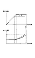
- the voltage control rate (also referred to as the modulation rate) of the inverter circuit is added to the compensation amount for reducing the harmonic component of the input power of the motor.
- the DC component of the voltage control rate it is necessary to reduce the DC component of the voltage control rate so that the compensation amount is not saturated. Since the size of the operating range of the motor (for example, the maximum rotation speed) is proportional to the DC component of the voltage control rate, the operating range of the motor must be lowered as the compensation amount is increased (see FIG. 3).
- FIG. 4 is a diagram for explaining a second related technique (Japanese Patent Laid-Open No. 2012-165634) for reducing the harmonic component of the input power of the motor.
- the compensation value (d-axis compensation voltage vd_h and q-axis compensation voltage vq_h) that distorts the motor current is set to the output of the current control unit (command value for controlling the motor current (d-axis voltage command value vd *).
- the q-axis voltage command value vq *) is superimposed to generate new voltage command values vd'* and vq' *.
- the voltage control rate also changes. Therefore, as in the first related technology, it is necessary to reduce the DC component of the voltage control factor (the magnitude of the voltage vector consisting of the output (vd *, vq *) of the current control unit) so that the compensation value is not saturated. Therefore, there is no choice but to lower the operating range of the motor (see FIG. 3).
- FIG. 5 is a diagram for explaining the technique of the present disclosure for reducing the harmonic component of the input power of the motor.
- a harmonic component generated in synchronization with the rotation speed of the motor is detected in the input power of the motor, and the inverter circuit has the same frequency as the detected harmonic component so that the harmonic component is reduced.
- the phase of the AC voltage output from is changed.
- the phase ⁇ of the entire voltage vector is at the same frequency as the detected harmonic component without changing the voltage control factor. Operate to pulsate.
- phase ⁇ Manipulating the phase ⁇ at the same frequency as the harmonic component of the input power of the motor causes the trajectories of the d-axis voltage and q-axis voltage to transition on the same arc at the same frequency as the harmonic component of the input power of the motor. Is equivalent to that.
- the AC voltage output from the inverter circuit is the harmonic obtained by adding the drive frequency of the motor to the frequency of the harmonic component of the input power of the motor.
- the wave component and the harmonic component obtained by subtracting the drive frequency of the motor from the frequency of the harmonic component of the input power of the motor appear with the same amplitude.
- Equations 1, 2 and 3 show the u-phase AC voltage output from the inverter circuit when the phase ⁇ of the entire voltage vector is pulsated.
- v u is the u-phase AC voltage (u-phase voltage of the motor) output from the inverter circuit
- V u is the amplitude of the u-phase voltage
- ⁇ e is the rotation angle (electric angle) of the rotor of the motor
- ⁇ ' is the inverter circuit. It represents the difference (voltage phase) between the phase of the AC voltage output from and the rotation angle of the inverter of the motor.
- (6 ⁇ e + B) represents a compensation amount (hereinafter, also referred to as compensation amount C) for compensating the voltage phase reference value ⁇ in order to compensate for the harmonics of the input power of the motor
- A is the amplitude of the compensation amount C.
- B represents the reference phase of the compensation amount C.
- Equation 3 The amplitude "-(1/2) AV u " in the second term of Equation 3 corresponds to the amplitude of the harmonic component obtained by subtracting the drive frequency of the motor from the frequency of the harmonic component of the input power of the motor.
- the amplitude "-(1/2) AV u " in the third term of Equation 3 corresponds to the amplitude of the harmonic component obtained by adding the drive frequency of the motor to the frequency of the harmonic component of the input power of the motor.
- Equations 1, 2 and 3 exemplify the case where the entire voltage vector is pulsated by a sine wave, but the entire voltage vector may be pulsated by another periodic waveform such as a triangular wave or a square wave.
- the phase of the AC voltage output from the inverter circuit is changed to the same frequency as the harmonic component generated in synchronization with the rotation speed of the motor with the input power of the motor, so that the harmonic generated in the input power of the motor
- the wave component can be reduced.
- a permanent magnet type synchronous motor is taken, but other types of motors can also be applied.
- a higher-order harmonic component such as 12 times or 18 times the drive frequency can also be reduced.
- v d is the d-axis voltage
- v q is the q-axis voltage
- Ra is the winding resistance of the motor armature
- L d is the d-axis inductance
- L q is the q-axis inductance
- id is the d-axis current
- i q is.
- omega e is the electrical angular velocity
- s is the time derivative of the operator of the motor
- phi d is the d-axis flux
- phi q is q-axis flux
- K d6 is the d-axis magnetic flux
- the amplitude, ⁇ a represents the magnetic flux of the permanent magnet.
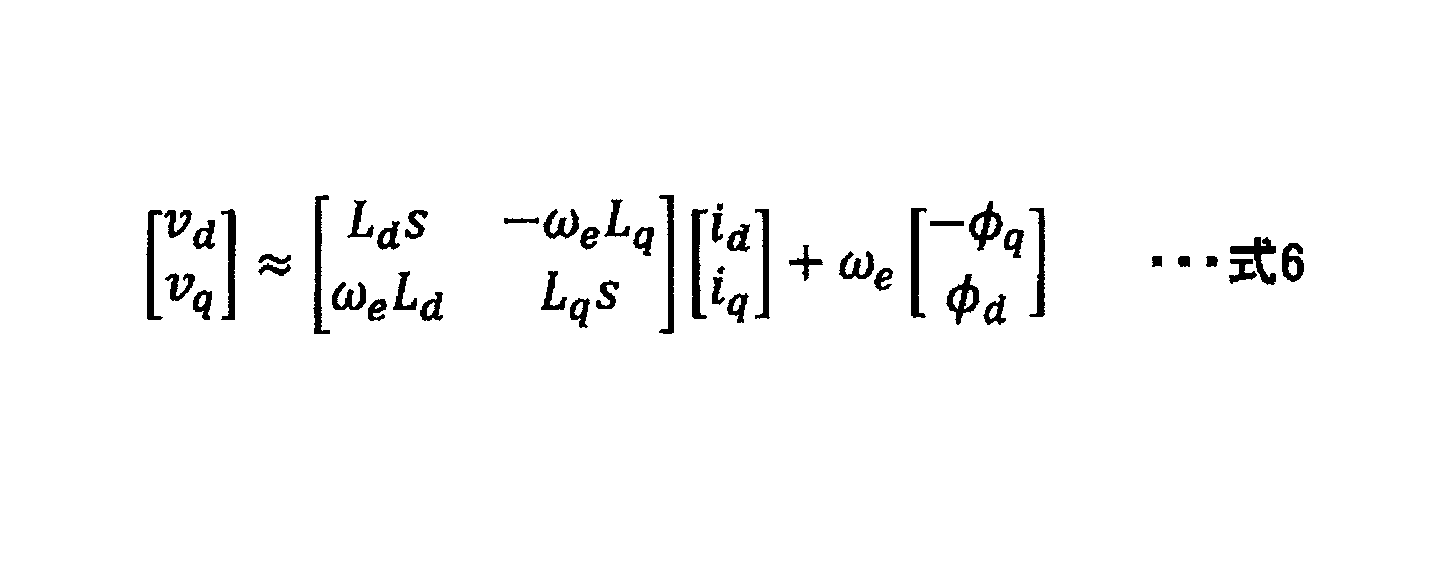
- Equation 4 is transformed into Equation 6.
- Equation 7 the d-axis voltage v d and the q-axis voltage v q are defined as equations 7 and 8.
- V a represents the amplitude of the d-axis voltage v d and the q-axis voltage v q.
- Equation 10 is obtained by solving the current in the simultaneous equations consisting of equations 6 and 9.
- Equation 11 When determining the input power P in the motor, Equation 11 is obtained.
- the power P in6 the sixth-order harmonic component is deformable to equation 12 (since the power of the 12-order harmonic component is a small, ignored).
- FIG. 6 is a diagram illustrating the relationship between the amplitude A and the electric power Pin 6 of the sixth-order harmonic component when the reference phase B is fixed in the equation 12.
- FIG. 7 is a diagram illustrating the relationship between the reference phase B and the electric power Pin 6 of the sixth-order harmonic component when the amplitude A is fixed in the equation 12.
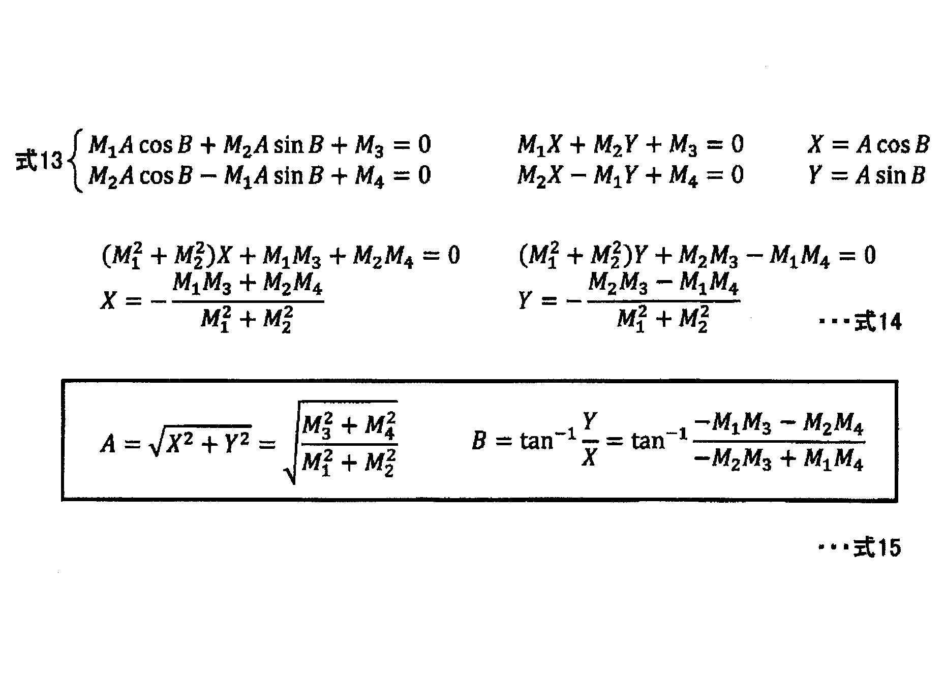
- Equation 12 when the condition that the power Pin6 of the sixth-order harmonic component becomes zero is obtained, the amplitude of the cosine component of the first term of Equation 12 is set to zero and the amplitude of the cosine component of the first term of Equation 12 is set to zero as in Equation 13. Let the amplitude of the sine component of the second term be zero. Equation 15 is obtained by solving the simultaneous equations represented by equations 13 and 14 for the amplitude A and the reference phase B.
- the power Pin6 of the sixth harmonic component is set to zero by adjusting each of the amplitude A and the reference phase B to appropriate values represented by the equation 15. You can also.
- the technique of the present disclosure detects a harmonic component generated in synchronization with the rotation speed of the motor in the input power of the motor, and at least one of the amplitude A and the reference phase B so that the harmonic is reduced. May be adjusted by using a mountain climbing method or the like according to the detected harmonic component.
- the sixth-order component of the motor current in the rotating coordinates does not become zero in the manipulated variable that makes the sixth-order harmonic component of the motor input power zero.
- the motor The sixth component of the input power of can be set to zero.
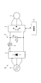
- FIG. 10 is a block diagram showing a first configuration example of the power conversion device to which the technique of the present disclosure is applied.
- the power conversion device 1A shown in FIG. 10 includes a converter circuit 2, a DC link unit 3, an inverter circuit 4, and a control unit 5, and uses input AC power supplied from a three-phase AC power supply 6 at a predetermined voltage and a predetermined frequency. It is converted into the output AC power of the above and supplied to the motor 7.
- the motor 7 is, for example, a three-phase AC motor for driving a compressor provided in a refrigerant circuit of an air conditioner. More specifically, the motor 7 is a centralized winding motor such as a 4-pole 6-slot or a 6-pole 9-slot. In this motor 7, there is a tendency that many 5th and 7th order components of the fundamental wave are included as harmonic components of the induced voltage. Higher-order (for example, 6th-order) harmonic components caused by this motor voltage distortion (5th and 7th-order harmonic components of the fundamental wave) are the power supply current of the AC power supply 6 and the DC link voltage in the DC link unit 3. It also appears in v dc.
- the converter circuit 2 is connected to the AC power supply 6 and converts the AC output by the AC power supply 6 into direct current.
- the converter circuit 2 is, for example, a diode bridge circuit in which a plurality of (six in this example) diodes are connected in a bridge shape. These diodes full-wave rectify the AC voltage of the AC power supply 6 and convert it into a DC voltage.
- the converter circuit 2 may be a voltage conversion circuit having a circuit type different from that of the diode bridge, as long as it is a circuit that supplies the converted DC power to the inverter circuit 4 via the DC link unit 3.
- the DC link unit 3 includes a capacitor 3a connected between the converter circuit 2 and the inverter circuit 4.
- the capacitor 3a is connected in parallel to the output section of the converter circuit 2, and the DC voltage (DC link voltage vdc ) generated across the capacitor 3a is input to the input node of the inverter circuit 4. Further description of the capacitor 3a will be described later.
- the DC link unit 3 includes a reactor 8 connected between the converter circuit 2 and the inverter circuit 4.
- the reactor 8 is inserted in series with the DC bus between the output unit of the converter circuit 2 and the input unit of the inverter circuit 4.
- the input node is connected in parallel to the capacitor 3a of the DC link unit 3, the output of the DC link unit 3 is switched, converted into three-phase alternating current, and supplied to the connected motor 7.
- the inverter circuit 4 of the present embodiment is configured by bridging a plurality of switching elements. Since the inverter circuit 4 outputs three-phase alternating current to the motor 7, it includes six switching elements. Specifically, the inverter circuit 4 comprises three switching legs connected in parallel to each other, and each switching leg has two switching elements connected in series with each other. In each switching leg, the midpoints of the switching element of the upper arm and the switching element of the lower arm are connected to the coils of each phase of the motor 7, respectively.
- a freewheeling diode is connected to each switching element in antiparallel.
- the inverter circuit 4 switches the DC link voltage vdc input from the DC link unit 3 by the on / off operation of these switching elements, converts it into a three-phase AC voltage, and supplies it to the motor 7.
- the control unit 5 controls this on / off operation.
- the control unit 5 detects a harmonic component generated in synchronization with the rotation speed of the motor 7 in the input power of the motor 7, and an inverter at the same frequency as the detected harmonic component so that the harmonic component is reduced.
- the phase of the AC voltage output from the circuit 4 is changed.
- the control unit 5 controls switching (on / off operation) in the inverter circuit 4 so that the phase of the AC voltage changes in this way.
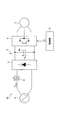
- FIG. 11 is a diagram showing a second configuration example of the power conversion device to which the technique of the present disclosure is applied.
- the description of the same configuration as that of the first configuration example will be omitted by referring to the above description.
- the power conversion device 1B shown in FIG. 11 includes a converter circuit 2, a DC link unit 3, an inverter circuit 4, and a control unit 5, and receives input AC power supplied from a single-phase AC power supply 6 at a predetermined voltage and a predetermined frequency. It is converted into the output AC power of the above and supplied to the motor 7.
- the converter circuit 2 is connected to the AC power supply 6 via the reactor 8 and rectifies (converts) the AC output from the AC power supply 6 to direct current.
- the converter circuit 2 is, for example, a diode bridge circuit in which a plurality of (four in this example) diodes are connected in a bridge shape. These diodes full-wave rectify the AC voltage of the AC power supply 6 and convert it into a DC voltage.
- the converter circuit 2 may be a voltage conversion circuit having a circuit type different from that of the diode bridge, as long as it is a circuit that supplies the converted DC power to the inverter circuit 4 via the DC link unit 3.
- the reactor 8 is connected between the AC power supply 6 and the converter circuit 2, and more specifically, the reactor 8 is inserted in series between the AC output side of the AC power supply 6 and the AC input side of the converter circuit 2. There is.
- the capacitance value of the capacitor 3a while can hardly smoothing the output of the converter circuit 2, a voltage variation corresponding to the ripple voltage (switching frequency f c due to the switching operation of the inverter circuit 4 ) Is set so that it can be suppressed.
- the capacitor 3a has a capacitance value (for example, about 0.01 times) the capacitance value of a smoothing capacitor (for example, an electrolytic capacitor) used for smoothing the output of the converter circuit 2 in a general power conversion device. It is composed of a small-capacity capacitor (for example, a film capacitor) having several tens to several hundreds of ⁇ F).
- the DC link voltage vdc has a pulsating component having a frequency six times the frequency of the power supply voltage bin, and in the case of the single-phase AC power supply 6 shown in FIG. has twice the pulsating component of the frequency of the power supply voltage v in.
- an LC filter composed of the reactor 8 and the capacitor 3a is configured.
- the resonance frequency f r of the LC filter is N times the frequency of the commercial frequency f in of the AC power supply 6 of the N phase, and to attenuate ripple voltage caused by the switching operation of the inverter circuit 4, the reactor
- the inductance of 8 and the capacitance value of the capacitor 3a are set.
- L represents the inductance of the reactor 8 and C represents the capacitance value of the capacitor 3a.
- the power conversion device is a capacitorless inverter (more specifically, an electrolytic capacitorless inverter) in which the capacitance value of the capacitor 3a of the DC link portion 3 is small as described above, a distortion component (harmonic component) generated in the input power of the motor 7. Harmonics due to the above may flow out to the power supply side. Similarly, even when the power converter is a matrix converter, harmonics due to distortion components generated in the input power of the motor may flow out to the power supply side.
- the control unit 5 has the phase of the AC voltage output from the inverter circuit 4 at the same frequency as the harmonic component so that the harmonic component generated in synchronization with the rotation speed of the motor 7 is reduced to the input power of the motor 7.
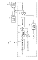
- FIG. 12 is a block diagram showing a first configuration example of the control unit.
- the control unit 5A shown in FIG. 12 is an example of the control unit 5.
- the control unit 5A outputs a gate signal G, which is a control signal for turning on / off each switching element in the inverter circuit 4, to the inverter circuit 4.
- the control unit 5A includes a motor control unit 11, a compensation unit 20, an adder 13, and a PWM calculation unit 12.
- the functions of each of these units included in the control unit 5A are realized by operating a processor (for example, a CPU (Central Processing Unit)) by a program readable and stored in a memory.
- a processor for example, a CPU (Central Processing Unit)
- the motor control unit 11 generates and outputs a voltage phase reference value ⁇ for controlling the phase of the AC voltage output from the inverter circuit 4 and a voltage control rate K s of the inverter circuit 4.
- the voltage control factor is also called a modulation factor.
- the compensation unit 20 compensates for the harmonics of the input power of the motor 7.
- the compensation unit 20 detects a harmonic component generated in synchronization with the rotation speed of the motor 7 in the input power of the motor 7, and an inverter at the same frequency as the detected harmonic component so that the harmonic component is reduced.
- the phase of the AC voltage output from the circuit 4 is changed.
- the compensation unit 20 adjusts the reference phase B of the compensation amount C according to the amplitude a of the detected harmonic component, and adjusts the amplitude A of the compensation amount C to the rotation speed of the motor 7 (electrical angular velocity ⁇ e). ), is changed according to one of the input power P in0 output torque T e and the motor 7 of the motor 7.
- the compensation unit 20 includes a harmonic component detection unit 21, a reference phase calculation unit 22, an integrator 23, an adder 24, a waveform generation unit 25, an amplitude calculation unit 26, and a multiplier 27.
- the harmonic component detection unit 21 detects the amplitude a of the harmonic component generated in synchronization with the rotation speed of the motor 7 with the input power of the motor 7 by Fourier transform or the like. Since a harmonic of the same order as the sixth-order harmonic component generated in the input power of the motor is also generated in the power on the input side of the inverter circuit, for example, the harmonic component detection unit 21 is a DC link voltage across the capacitor 3a. From v dc , the amplitude a of the harmonic component generated in the input power of the motor 7 is detected. Alternatively, the harmonic component detection unit 21 may detect the amplitude a of the harmonic component generated in the input power of the motor 7 from the reactor voltage v L at both ends of the reactor 8.
- the harmonic component detector 21, the reactor current i L flowing through the reactor 8 may detect the amplitude a of the harmonic components generated in the input power of the motor 7.
- the harmonic component detection unit 21 may actually monitor the input power of the motor 7 and detect the amplitude a of the harmonic component generated in the input power of the motor 7 from the monitor value.
- the harmonic component detection unit 21 acquires a signal for detecting the amplitude a of the harmonic component during a period in which the voltage vector of the inverter circuit 4 does not change (for example, a period in which a voltage vector having a magnitude of zero is output). .. As a result, the detection accuracy of the amplitude a is improved as compared with the case where the signal for detecting the amplitude a is acquired during the period when the voltage vector changes.
- the reference phase calculation unit 22 adjusts the reference phase B of the compensation amount C according to the amplitude a of the harmonic component detected by the harmonic component detection unit 21.
- the reference phase calculation unit 22 uses a mountain climbing method so that the detected amplitude a becomes smaller according to the amplitude a detected by the harmonic component detection unit 21, for example, the reference phase B of the compensation amount C. To adjust.
- an optimum reference phase B (an example of a target value of the reference phase B) that reduces the amplitude of the harmonic component generated in the input power of the motor 7 can be obtained.
- the compensation unit 20 generates 6 ⁇ e by integrating the frequency 6 times the rotation speed (electric angular velocity ⁇ e) of the motor 7 with the integrator 23.
- (6 ⁇ e + B) is obtained by adding the reference phase B calculated by the reference phase calculation unit 22 and the 6 ⁇ e obtained by the integrator 23 by the adder 24.
- the waveform generation unit 25 generates a sinusoidal sin (6 ⁇ e + B) having a phase (6 ⁇ e + B) synchronized with the rotation speed of the motor 7.
- 6 ⁇ e + B is obtained by adding the reference phase B calculated by the reference phase calculation unit 22 and the 6 ⁇ e obtained by the integrator 23 by the adder 24.
- the waveform generation unit 25 generates a sinusoidal sin (6 ⁇ e + B) having a phase (6 ⁇ e + B) synchronized with the rotation speed of the motor 7.
- the amplitude calculation unit 26 determines the optimum amplitude A from the detected value or the command value of the electric angular velocity ⁇ e based on the correlation between the electric angular velocity ⁇ e and the amplitude A in which the power supply harmonic is equal to or less than the harmonic regulation value. (An example of the target value of amplitude A) is generated.
- the correlation at which the power supply harmonic is equal to or less than the harmonic regulation value is, for example, a relational rule determined in advance by a test or the like, and is defined by a look-up table or an arithmetic expression.
- the electrical angular velocity omega e was replaced with the output torque T e and the input power P in0, by using such a correlation, the optimum amplitude A is obtained.
- the voltage phase reference value ⁇ generated by the motor control unit 11 and the compensation amount C generated by the multiplier 27 are added by the adder 13 to generate the voltage phase ⁇ '.
- the PWM calculation unit 12 generates three-phase voltage command values of u-phase, v-phase, and w-phase from the voltage control rate K s and the voltage phase ⁇ 'using polar coordinate conversion, inverse park conversion, space vector conversion, and the like. To do.
- the three-phase voltage command value is a PWM (pulse width modulation) signal.
- PWM computing unit 12 by adjusting accordingly the amplitude of the voltage command values of three phases to the voltage control rate K s, it may control the magnitude of the AC voltage outputted from the inverter circuit 4.
- the PWM calculation unit 12 converts the three-phase voltage command value into a gate signal G and outputs it to the inverter circuit 4.
- the control unit 5A detects the harmonic component caused by the distortion generated in the input power of the motor 7, and the inverter circuit has the same frequency as the harmonic component according to the amplitude a of the detected harmonic component.
- the phase of the AC voltage output from 4 is fluctuated to reduce its harmonic components.
- FIG. 13 is a block diagram showing a second configuration example of the control unit. The description of the same configuration as that of the first configuration example will be omitted by referring to the above description.
- the control unit 5B shown in FIG. 13 is an example of the control unit 5.
- the control unit 5B includes a compensation unit 30.
- the compensation unit 30 adjusts the amplitude A of the compensation amount C according to the amplitude a of the detected harmonic component, and sets the reference phase B of the compensation amount C to the rotation speed of the motor 7 (electrical angular velocity ⁇ e). ), is changed according to one of the input power P in0 output torque T e and the motor 7 of the motor 7.
- the compensation unit 30 includes a harmonic component detection unit 21, a reference phase calculation unit 22, an integrator 23, an adder 24, a waveform generation unit 25, an amplitude calculation unit 26, and a multiplier 27.
- Reference phase calculator 22 a reference phase B of the compensation amount C, the rotation speed of the motor 7 (electrical angular velocity omega e), according to any one of the input power P in0 output torque T e and the motor 7 of the motor 7 To change.
- the reference phase calculation unit 22 is, for example, an optimum reference from the detected value or the command value of the electric angular velocity ⁇ e based on the correlation between the electric angular velocity ⁇ e and the amplitude A in which the power supply harmonic is equal to or less than the harmonic regulation value.
- Generate phase B an example of a target value of reference phase B).
- the correlation at which the power supply harmonic is equal to or less than the harmonic regulation value is, for example, a relational rule determined in advance by a test or the like, and is defined by a look-up table or an arithmetic expression.
- the optimum reference phase B is obtained.
- the amplitude calculation unit 26 adjusts the amplitude A of the compensation amount C according to the amplitude a of the harmonic component detected by the harmonic component detection unit 21. For example, the amplitude calculation unit 26 adjusts the amplitude A of the compensation amount C by using the mountain climbing method so that the detected amplitude a becomes smaller according to the amplitude a detected by the harmonic component detection unit 21. To do. As a result, an optimum amplitude A (an example of a target value of the amplitude A) for reducing the amplitude of the harmonic component generated in the input power of the motor 7 can be obtained.
- the voltage phase reference value ⁇ generated by the motor control unit 11 and the compensation amount C generated by the multiplier 27 are added by the adder 13 to generate the voltage phase ⁇ '.
- the control unit 5B detects the harmonic component caused by the distortion generated in the input power of the motor 7, and the inverter circuit has the same frequency as the harmonic component according to the amplitude a of the detected harmonic component.
- the phase of the AC voltage output from 4 is fluctuated to reduce its harmonic components.
- FIG. 14 is a block diagram showing a third configuration example of the control unit. The description of the same configuration as that of the third configuration example will be omitted by referring to the above description.
- the control unit 5C shown in FIG. 14 is an example of the control unit 5.
- the control unit 5C includes a compensation unit 40.
- the compensation unit 40 adjusts the amplitude A and the reference phase B of the compensation amount C according to the amplitude a of the detected harmonic component.
- the compensation unit 30 includes a harmonic component detection unit 21, a reference phase calculation unit 22, an integrator 23, an adder 24, a waveform generation unit 25, an amplitude calculation unit 26, and a multiplier 27.
- the reference phase calculation unit 22 has the same function as the first configuration example (FIG. 12), and the amplitude calculation unit 26 has the same function as the second configuration example (FIG. 13).
- the control unit 5C detects a harmonic component caused by distortion generated in the input power of the motor 7, and outputs the harmonic component from the inverter circuit 4 at the same frequency as the harmonic component according to the amplitude a of the detected harmonic component.
- the phase of the AC voltage is changed to reduce its harmonic components.
- FIGS. 8 and 9 are diagrams showing an example of the test results when the motor is driven by the actual machine by the technique of the present disclosure, and show the case where the motor is actually driven by the power conversion device having the configuration shown in FIGS. 10 and 12. Shown.
- the vertical axis represents the power supply harmonics generated on the AC power supply 6 side due to the power Pin 6 of the sixth-order harmonic component of the input power of the motor 7.
- the power supply harmonics change. Since there are amplitude A and reference phase B in which the amplitudes of the 30th and 32nd order power supply harmonics are substantially zero, the respective amplitudes of the 30th and 32nd order power supply harmonics satisfy the power supply harmonic regulation value. be able to.
Abstract
Description
交流電源から供給された入力交流電力を所定の電圧及び周波数の出力交流電力に電力変換する電力変換装置であって、
前記出力交流電力をモータに供給するインバータ回路と、
前記モータの入力電力の高調波を補償する補償部とを備え、
前記補償部は、前記入力電力に前記モータの回転数に同期して発生する高調波成分を検出し、前記高調波成分が低減するように、前記高調波成分と同じ周波数で、前記インバータ回路から出力される交流電圧の位相を変化させる。 The power converter of the present disclosure is
A power conversion device that converts input AC power supplied from an AC power supply into output AC power of a predetermined voltage and frequency.
The inverter circuit that supplies the output AC power to the motor and
A compensation unit for compensating for harmonics of the input power of the motor is provided.
The compensating unit detects a harmonic component generated in synchronization with the rotation speed of the motor in the input power, and from the inverter circuit at the same frequency as the harmonic component so that the harmonic component is reduced. Change the phase of the output alternating voltage.
前記補償部は、前記高調波成分と同じ周波数で変化する補償量を生成し、前記補償量に基づいて前記交流電圧の位相を前記高調波成分と同じ周波数で変化させる。 The power converter of the present disclosure is
The compensation unit generates a compensation amount that changes at the same frequency as the harmonic component, and changes the phase of the AC voltage at the same frequency as the harmonic component based on the compensation amount.
前記補償部は、前記補償量の位相を、検出した前記高調波成分に応じて調整し、前記補償量の振幅を、前記モータの回転数、トルク及び電力のうちのいずれかに応じて変更する。 The power converter of the present disclosure is
The compensation unit adjusts the phase of the compensation amount according to the detected harmonic component, and changes the amplitude of the compensation amount according to any one of the rotation speed, torque, and electric power of the motor. ..
前記補償部は、前記補償量の振幅を、検出した前記高調波成分に応じて調整し、前記補償量の位相を、前記モータの回転数、トルク及び電力のうちのいずれかに応じて変更する。 The power converter of the present disclosure is
The compensation unit adjusts the amplitude of the compensation amount according to the detected harmonic component, and changes the phase of the compensation amount according to any one of the rotation speed, torque, and electric power of the motor. ..
前記補償部は、前記補償量の位相及び振幅を、検出した前記高調波成分に応じて調整する。 The power converter of the present disclosure is
The compensation unit adjusts the phase and amplitude of the compensation amount according to the detected harmonic component.
前記入力交流電力を整流し、前記インバータ回路に電力供給するコンバータ回路を備え、
前記コンバータ回路と前記インバータ回路との間に、前記コンバータ回路と並列にコンデンサが接続され、
前記補償部は、前記コンデンサの両端の電圧から前記高調波成分を検出する。 The power converter of the present disclosure is
A converter circuit that rectifies the input AC power and supplies power to the inverter circuit is provided.
A capacitor is connected in parallel with the converter circuit between the converter circuit and the inverter circuit.
The compensator detects the harmonic component from the voltage across the capacitor.
前記電力変換装置は、前記入力交流電力を整流し、前記インバータ回路に電力供給するコンバータ回路を備え、
前記コンバータ回路と前記交流電源または前記インバータ回路との間にリアクトルが接続され、
前記補償部は、前記リアクトルの両端の電圧から前記高調波成分を検出する。 The power converter of the present disclosure is
The power conversion device includes a converter circuit that rectifies the input AC power and supplies power to the inverter circuit.
A reactor is connected between the converter circuit and the AC power supply or the inverter circuit.
The compensator detects the harmonic component from the voltage across the reactor.
前記電力変換装置は、前記入力交流電力を整流し、前記インバータ回路に電力供給するコンバータ回路を備え、
前記コンバータ回路と前記交流電源または前記インバータ回路との間にリアクトルが接続され、
前記補償部は、前記リアクトルに流れる電流から前記高調波成分を検出する。 The power converter of the present disclosure is
The power conversion device includes a converter circuit that rectifies the input AC power and supplies power to the inverter circuit.
A reactor is connected between the converter circuit and the AC power supply or the inverter circuit.
The compensator detects the harmonic component from the current flowing through the reactor.
前記補償部は、前記高調波成分を検出するための信号を、前記インバータ回路の電圧ベクトルが変化しない期間に取得する。 The power converter of the present disclosure is
The compensation unit acquires a signal for detecting the harmonic component during a period in which the voltage vector of the inverter circuit does not change.


fr=1(2π√LC)
Lはリアクトル8のインダクタンス、Cはコンデンサ3aの容量値を表す。 N × f in ≦ f r ≦ f c / 4
f r = 1 (2π√LC)
L represents the inductance of the
4 インバータ回路
5,5A,5B,5C 制御部
6 交流電源
7 モータ
8 リアクトル
20,30,40 補償部 1A,
Claims (9)
- 交流電源から供給された入力交流電力を所定の電圧及び周波数の出力交流電力に電力変換する電力変換装置であって、
前記出力交流電力をモータに供給するインバータ回路と、
前記モータの入力電力の高調波を補償する補償部とを備え、
前記補償部は、前記入力電力に前記モータの回転数に同期して発生する高調波成分を検出し、前記高調波成分が低減するように、前記高調波成分と同じ周波数で、前記インバータ回路から出力される交流電圧の位相を変化させる、電力変換装置。 A power conversion device that converts input AC power supplied from an AC power supply into output AC power of a predetermined voltage and frequency.
The inverter circuit that supplies the output AC power to the motor and
A compensation unit for compensating for harmonics of the input power of the motor is provided.
The compensating unit detects a harmonic component generated in synchronization with the rotation speed of the motor in the input power, and from the inverter circuit at the same frequency as the harmonic component so that the harmonic component is reduced. A power converter that changes the phase of the output alternating voltage. - 前記補償部は、前記高調波成分と同じ周波数で変化する補償量を生成し、前記補償量に基づいて前記交流電圧の位相を前記高調波成分と同じ周波数で変化させる、請求項1に記載の電力変換装置。 The compensation unit according to claim 1, wherein the compensation unit generates a compensation amount that changes at the same frequency as the harmonic component, and changes the phase of the AC voltage at the same frequency as the harmonic component based on the compensation amount. Power converter.
- 前記補償部は、前記補償量の位相を、検出した前記高調波成分に応じて調整し、前記補償量の振幅を、前記モータの回転数、トルク及び電力のうちのいずれかに応じて変更する、請求項2に記載の電力変換装置。 The compensation unit adjusts the phase of the compensation amount according to the detected harmonic component, and changes the amplitude of the compensation amount according to any one of the rotation speed, torque, and electric power of the motor. , The power conversion device according to claim 2.
- 前記補償部は、前記補償量の振幅を、検出した前記高調波成分に応じて調整し、前記補償量の位相を、前記モータの回転数、トルク及び電力のうちのいずれかに応じて変更する、請求項2に記載の電力変換装置。 The compensation unit adjusts the amplitude of the compensation amount according to the detected harmonic component, and changes the phase of the compensation amount according to any one of the rotation speed, torque, and electric power of the motor. , The power conversion device according to claim 2.
- 前記補償部は、前記補償量の位相及び振幅を、検出した前記高調波成分に応じて調整する、請求項2に記載の電力変換装置。 The power conversion device according to claim 2, wherein the compensation unit adjusts the phase and amplitude of the compensation amount according to the detected harmonic component.
- 前記電力変換装置は、前記入力交流電力を整流し、前記インバータ回路に電力供給するコンバータ回路を備え、
前記コンバータ回路と前記インバータ回路との間に、前記コンバータ回路と並列にコンデンサが接続され、
前記補償部は、前記コンデンサの両端の電圧から前記高調波成分を検出する、請求項1から5のいずれか一項に記載の電力変換装置。 The power conversion device includes a converter circuit that rectifies the input AC power and supplies power to the inverter circuit.
A capacitor is connected in parallel with the converter circuit between the converter circuit and the inverter circuit.
The power conversion device according to any one of claims 1 to 5, wherein the compensation unit detects the harmonic component from the voltage across the capacitor. - 前記電力変換装置は、前記入力交流電力を整流し、前記インバータ回路に電力供給するコンバータ回路を備え、
前記コンバータ回路と前記交流電源または前記インバータ回路との間にリアクトルが接続され、
前記補償部は、前記リアクトルの両端の電圧から前記高調波成分を検出する、請求項1から5のいずれか一項に記載の電力変換装置。 The power conversion device includes a converter circuit that rectifies the input AC power and supplies power to the inverter circuit.
A reactor is connected between the converter circuit and the AC power supply or the inverter circuit.
The power conversion device according to any one of claims 1 to 5, wherein the compensation unit detects the harmonic component from the voltage across the reactor. - 前記電力変換装置は、前記入力交流電力を整流し、前記インバータ回路に電力供給するコンバータ回路を備え、
前記コンバータ回路と前記交流電源または前記インバータ回路との間にリアクトルが接続され、
前記補償部は、前記リアクトルに流れる電流から前記高調波成分を検出する、請求項1から5のいずれか一項に記載の電力変換装置。 The power conversion device includes a converter circuit that rectifies the input AC power and supplies power to the inverter circuit.
A reactor is connected between the converter circuit and the AC power supply or the inverter circuit.
The power conversion device according to any one of claims 1 to 5, wherein the compensation unit detects the harmonic component from the current flowing through the reactor. - 前記補償部は、前記高調波成分を検出するための信号を、前記インバータ回路の電圧ベクトルが変化しない期間に取得する、請求項1から8のいずれか一項に記載の電力変換装置。 The power conversion device according to any one of claims 1 to 8, wherein the compensation unit acquires a signal for detecting the harmonic component during a period in which the voltage vector of the inverter circuit does not change.
Priority Applications (3)
| Application Number | Priority Date | Filing Date | Title |
|---|---|---|---|
| CN202080073116.1A CN114556767A (en) | 2019-10-23 | 2020-10-21 | Power conversion device |
| AU2020371391A AU2020371391B2 (en) | 2019-10-23 | 2020-10-21 | Power conversion device |
| EP20878173.2A EP4050788A4 (en) | 2019-10-23 | 2020-10-21 | Power conversion device |
Applications Claiming Priority (2)
| Application Number | Priority Date | Filing Date | Title |
|---|---|---|---|
| JP2019192870A JP7311778B2 (en) | 2019-10-23 | 2019-10-23 | power converter |
| JP2019-192870 | 2019-10-23 |
Publications (1)
| Publication Number | Publication Date |
|---|---|
| WO2021079919A1 true WO2021079919A1 (en) | 2021-04-29 |
Family
ID=75620078
Family Applications (1)
| Application Number | Title | Priority Date | Filing Date |
|---|---|---|---|
| PCT/JP2020/039624 WO2021079919A1 (en) | 2019-10-23 | 2020-10-21 | Power conversion device |
Country Status (5)
| Country | Link |
|---|---|
| EP (1) | EP4050788A4 (en) |
| JP (1) | JP7311778B2 (en) |
| CN (1) | CN114556767A (en) |
| AU (1) | AU2020371391B2 (en) |
| WO (1) | WO2021079919A1 (en) |
Families Citing this family (1)
| Publication number | Priority date | Publication date | Assignee | Title |
|---|---|---|---|---|
| JP7283598B1 (en) | 2022-02-24 | 2023-05-30 | 株式会社明電舎 | Control device for voltage source inverter |
Citations (12)
| Publication number | Priority date | Publication date | Assignee | Title |
|---|---|---|---|---|
| JPH0454872A (en) * | 1990-06-22 | 1992-02-21 | Hitachi Ltd | Power converter |
| JPH05176584A (en) * | 1991-12-26 | 1993-07-13 | Hitachi Ltd | Controller for power converter |
| JPH1189297A (en) * | 1997-09-08 | 1999-03-30 | Toshiba Corp | Power converting device |
| JP2000287481A (en) * | 1999-03-31 | 2000-10-13 | Fujitsu General Ltd | Motor control method |
| WO2008139518A1 (en) * | 2007-04-27 | 2008-11-20 | Mitsubishi Electric Corporation | Power conversion system |
| JP2009044873A (en) * | 2007-08-09 | 2009-02-26 | Mitsubishi Electric Corp | Electric motor driver, compressor drive device, and compressor |
| JP2010098941A (en) | 2008-09-22 | 2010-04-30 | Daikin Ind Ltd | Power converter, control method thereof and direct matrix converter |
| JP2010239681A (en) * | 2009-03-30 | 2010-10-21 | Aisin Aw Co Ltd | Rotary electric machine control device |
| JP2012016276A (en) * | 2006-04-11 | 2012-01-19 | Nsk Ltd | Motor drive control apparatus and electric power steering apparatus using the same |
| JP2012165634A (en) | 2011-01-18 | 2012-08-30 | Daikin Ind Ltd | Power converter |
| JP2016208668A (en) * | 2015-04-22 | 2016-12-08 | 株式会社デンソー | Controller of three-phase rotary machine |
| JP2019192870A (en) | 2018-04-27 | 2019-10-31 | ローム株式会社 | Semiconductor integrated circuit device |
Family Cites Families (2)
| Publication number | Priority date | Publication date | Assignee | Title |
|---|---|---|---|---|
| JP5176584B2 (en) | 2008-02-20 | 2013-04-03 | 住友化学株式会社 | Laminated film |
| JP6195003B1 (en) * | 2016-09-30 | 2017-09-13 | ダイキン工業株式会社 | Inverter device |
-
2019
- 2019-10-23 JP JP2019192870A patent/JP7311778B2/en active Active
-
2020
- 2020-10-21 CN CN202080073116.1A patent/CN114556767A/en active Pending
- 2020-10-21 EP EP20878173.2A patent/EP4050788A4/en active Pending
- 2020-10-21 AU AU2020371391A patent/AU2020371391B2/en active Active
- 2020-10-21 WO PCT/JP2020/039624 patent/WO2021079919A1/en active Application Filing
Patent Citations (12)
| Publication number | Priority date | Publication date | Assignee | Title |
|---|---|---|---|---|
| JPH0454872A (en) * | 1990-06-22 | 1992-02-21 | Hitachi Ltd | Power converter |
| JPH05176584A (en) * | 1991-12-26 | 1993-07-13 | Hitachi Ltd | Controller for power converter |
| JPH1189297A (en) * | 1997-09-08 | 1999-03-30 | Toshiba Corp | Power converting device |
| JP2000287481A (en) * | 1999-03-31 | 2000-10-13 | Fujitsu General Ltd | Motor control method |
| JP2012016276A (en) * | 2006-04-11 | 2012-01-19 | Nsk Ltd | Motor drive control apparatus and electric power steering apparatus using the same |
| WO2008139518A1 (en) * | 2007-04-27 | 2008-11-20 | Mitsubishi Electric Corporation | Power conversion system |
| JP2009044873A (en) * | 2007-08-09 | 2009-02-26 | Mitsubishi Electric Corp | Electric motor driver, compressor drive device, and compressor |
| JP2010098941A (en) | 2008-09-22 | 2010-04-30 | Daikin Ind Ltd | Power converter, control method thereof and direct matrix converter |
| JP2010239681A (en) * | 2009-03-30 | 2010-10-21 | Aisin Aw Co Ltd | Rotary electric machine control device |
| JP2012165634A (en) | 2011-01-18 | 2012-08-30 | Daikin Ind Ltd | Power converter |
| JP2016208668A (en) * | 2015-04-22 | 2016-12-08 | 株式会社デンソー | Controller of three-phase rotary machine |
| JP2019192870A (en) | 2018-04-27 | 2019-10-31 | ローム株式会社 | Semiconductor integrated circuit device |
Also Published As
| Publication number | Publication date |
|---|---|
| JP7311778B2 (en) | 2023-07-20 |
| JP2021069187A (en) | 2021-04-30 |
| CN114556767A (en) | 2022-05-27 |
| EP4050788A4 (en) | 2023-11-15 |
| AU2020371391A1 (en) | 2022-05-12 |
| AU2020371391B2 (en) | 2023-01-05 |
| EP4050788A1 (en) | 2022-08-31 |
Similar Documents
| Publication | Publication Date | Title |
|---|---|---|
| JP6566105B2 (en) | Power converter | |
| RU2462806C1 (en) | Energy conversion device | |
| JP6079094B2 (en) | Inverter control device | |
| WO2018061546A1 (en) | Control device for power converter | |
| KR101485989B1 (en) | Motor control device | |
| CN113330680A (en) | Direct power conversion device | |
| WO2013047236A1 (en) | Power converter control method | |
| JP5813934B2 (en) | Power converter | |
| JP4253156B2 (en) | Inverter control method and apparatus | |
| JP6226901B2 (en) | Power generation system | |
| WO2021079919A1 (en) | Power conversion device | |
| JP3236985B2 (en) | Control device for PWM converter | |
| Hinkkanen et al. | Control of induction motor drives equipped with small DC-link capacitance | |
| JP2003061382A (en) | Control method of inverter and control circuit of inverter | |
| JP4401724B2 (en) | Power converter | |
| JP5755342B2 (en) | Motor drive system | |
| JP2017017918A (en) | Control apparatus of rotating machine driving device | |
| KR0181399B1 (en) | Unbalancing source voltage control apparatus of voltage type pwm converter and its method | |
| JP2016127649A (en) | Power conversion device | |
| KR101911267B1 (en) | Power transforming apparatus and air conditioner including the same | |
| KR20200058941A (en) | Inverter control apparatus | |
| JP5067424B2 (en) | Power converter | |
| JP2021048739A (en) | Inverter device and method for controlling inverter device | |
| JP2000175460A (en) | Method and system for converting power | |
| JP2015154612A (en) | control device |
Legal Events
| Date | Code | Title | Description |
|---|---|---|---|
| 121 | Ep: the epo has been informed by wipo that ep was designated in this application |
Ref document number: 20878173 Country of ref document: EP Kind code of ref document: A1 |
|
| WWE | Wipo information: entry into national phase |
Ref document number: 17754772 Country of ref document: US |
|
| NENP | Non-entry into the national phase |
Ref country code: DE |
|
| ENP | Entry into the national phase |
Ref document number: 2020371391 Country of ref document: AU Date of ref document: 20201021 Kind code of ref document: A |
|
| ENP | Entry into the national phase |
Ref document number: 2020878173 Country of ref document: EP Effective date: 20220523 |