WO2021070554A1 - 無線受電システム、移動体、及び車輪 - Google Patents
無線受電システム、移動体、及び車輪 Download PDFInfo
- Publication number
- WO2021070554A1 WO2021070554A1 PCT/JP2020/034377 JP2020034377W WO2021070554A1 WO 2021070554 A1 WO2021070554 A1 WO 2021070554A1 JP 2020034377 W JP2020034377 W JP 2020034377W WO 2021070554 A1 WO2021070554 A1 WO 2021070554A1
- Authority
- WO
- WIPO (PCT)
- Prior art keywords
- power receiving
- coil
- power
- receiving coil
- wheel
- Prior art date
Links
- 230000005540 biological transmission Effects 0.000 claims description 71
- 230000002093 peripheral effect Effects 0.000 claims description 21
- 238000004804 winding Methods 0.000 claims description 8
- 239000010410 layer Substances 0.000 description 80
- 238000003860 storage Methods 0.000 description 15
- 239000000696 magnetic material Substances 0.000 description 13
- 230000005291 magnetic effect Effects 0.000 description 10
- 239000011324 bead Substances 0.000 description 9
- 239000000758 substrate Substances 0.000 description 9
- 229920005989 resin Polymers 0.000 description 8
- 239000011347 resin Substances 0.000 description 8
- 230000006870 function Effects 0.000 description 7
- 229910052751 metal Inorganic materials 0.000 description 7
- 239000002184 metal Substances 0.000 description 7
- 238000005192 partition Methods 0.000 description 6
- 239000002356 single layer Substances 0.000 description 6
- 238000000034 method Methods 0.000 description 5
- OKTJSMMVPCPJKN-UHFFFAOYSA-N Carbon Chemical compound [C] OKTJSMMVPCPJKN-UHFFFAOYSA-N 0.000 description 4
- 238000012986 modification Methods 0.000 description 4
- 230000004048 modification Effects 0.000 description 4
- 229910000831 Steel Inorganic materials 0.000 description 3
- 238000006243 chemical reaction Methods 0.000 description 3
- 238000004891 communication Methods 0.000 description 3
- 230000005674 electromagnetic induction Effects 0.000 description 3
- 238000009434 installation Methods 0.000 description 3
- 239000011810 insulating material Substances 0.000 description 3
- 230000008569 process Effects 0.000 description 3
- 239000010959 steel Substances 0.000 description 3
- 238000003466 welding Methods 0.000 description 3
- 229910000859 α-Fe Inorganic materials 0.000 description 3
- IJGRMHOSHXDMSA-UHFFFAOYSA-N Atomic nitrogen Chemical compound N#N IJGRMHOSHXDMSA-UHFFFAOYSA-N 0.000 description 2
- 241001465754 Metazoa Species 0.000 description 2
- PXHVJJICTQNCMI-UHFFFAOYSA-N Nickel Chemical compound [Ni] PXHVJJICTQNCMI-UHFFFAOYSA-N 0.000 description 2
- 239000004698 Polyethylene Substances 0.000 description 2
- 229910052782 aluminium Inorganic materials 0.000 description 2
- XAGFODPZIPBFFR-UHFFFAOYSA-N aluminium Chemical compound [Al] XAGFODPZIPBFFR-UHFFFAOYSA-N 0.000 description 2
- 239000004760 aramid Substances 0.000 description 2
- 229920003235 aromatic polyamide Polymers 0.000 description 2
- 239000003990 capacitor Substances 0.000 description 2
- 229910052799 carbon Inorganic materials 0.000 description 2
- 239000000919 ceramic Substances 0.000 description 2
- 238000010276 construction Methods 0.000 description 2
- 239000002889 diamagnetic material Substances 0.000 description 2
- 230000000694 effects Effects 0.000 description 2
- 229920001971 elastomer Polymers 0.000 description 2
- 238000005516 engineering process Methods 0.000 description 2
- 230000004907 flux Effects 0.000 description 2
- 239000007789 gas Substances 0.000 description 2
- 239000011521 glass Substances 0.000 description 2
- 229910002804 graphite Inorganic materials 0.000 description 2
- 239000010439 graphite Substances 0.000 description 2
- 239000000463 material Substances 0.000 description 2
- 239000007769 metal material Substances 0.000 description 2
- 239000002907 paramagnetic material Substances 0.000 description 2
- -1 polyethylene Polymers 0.000 description 2
- 229920000573 polyethylene Polymers 0.000 description 2
- 239000005060 rubber Substances 0.000 description 2
- RYGMFSIKBFXOCR-UHFFFAOYSA-N Copper Chemical compound [Cu] RYGMFSIKBFXOCR-UHFFFAOYSA-N 0.000 description 1
- 244000043261 Hevea brasiliensis Species 0.000 description 1
- UFHFLCQGNIYNRP-UHFFFAOYSA-N Hydrogen Chemical compound [H][H] UFHFLCQGNIYNRP-UHFFFAOYSA-N 0.000 description 1
- HBBGRARXTFLTSG-UHFFFAOYSA-N Lithium ion Chemical compound [Li+] HBBGRARXTFLTSG-UHFFFAOYSA-N 0.000 description 1
- 239000004677 Nylon Substances 0.000 description 1
- BNOODXBBXFZASF-UHFFFAOYSA-N [Na].[S] Chemical compound [Na].[S] BNOODXBBXFZASF-UHFFFAOYSA-N 0.000 description 1
- 229910052802 copper Inorganic materials 0.000 description 1
- 239000010949 copper Substances 0.000 description 1
- 210000003298 dental enamel Anatomy 0.000 description 1
- 238000013461 design Methods 0.000 description 1
- 239000000428 dust Substances 0.000 description 1
- 239000000835 fiber Substances 0.000 description 1
- 239000012530 fluid Substances 0.000 description 1
- 239000008187 granular material Substances 0.000 description 1
- 229910052739 hydrogen Inorganic materials 0.000 description 1
- 239000001257 hydrogen Substances 0.000 description 1
- 239000007788 liquid Substances 0.000 description 1
- 229910001416 lithium ion Inorganic materials 0.000 description 1
- 238000004519 manufacturing process Methods 0.000 description 1
- 230000007246 mechanism Effects 0.000 description 1
- 150000002739 metals Chemical class 0.000 description 1
- 229920003052 natural elastomer Polymers 0.000 description 1
- 229920001194 natural rubber Polymers 0.000 description 1
- 229910052759 nickel Inorganic materials 0.000 description 1
- 229910052757 nitrogen Inorganic materials 0.000 description 1
- 229910052755 nonmetal Inorganic materials 0.000 description 1
- 229920001778 nylon Polymers 0.000 description 1
- 230000008520 organization Effects 0.000 description 1
- 230000035699 permeability Effects 0.000 description 1
- 229920000728 polyester Polymers 0.000 description 1
- 239000000843 powder Substances 0.000 description 1
- 238000012545 processing Methods 0.000 description 1
- 239000012783 reinforcing fiber Substances 0.000 description 1
- 230000004043 responsiveness Effects 0.000 description 1
- 239000000126 substance Substances 0.000 description 1
- 229920003051 synthetic elastomer Polymers 0.000 description 1
- 229920003002 synthetic resin Polymers 0.000 description 1
- 239000000057 synthetic resin Substances 0.000 description 1
- 239000005061 synthetic rubber Substances 0.000 description 1
- 229920005992 thermoplastic resin Polymers 0.000 description 1
- 229920001187 thermosetting polymer Polymers 0.000 description 1
- 229920006337 unsaturated polyester resin Polymers 0.000 description 1
- 229920001567 vinyl ester resin Polymers 0.000 description 1
Images


Classifications
-
- H—ELECTRICITY
- H02—GENERATION; CONVERSION OR DISTRIBUTION OF ELECTRIC POWER
- H02J—CIRCUIT ARRANGEMENTS OR SYSTEMS FOR SUPPLYING OR DISTRIBUTING ELECTRIC POWER; SYSTEMS FOR STORING ELECTRIC ENERGY
- H02J50/00—Circuit arrangements or systems for wireless supply or distribution of electric power
- H02J50/10—Circuit arrangements or systems for wireless supply or distribution of electric power using inductive coupling
-
- B—PERFORMING OPERATIONS; TRANSPORTING
- B60—VEHICLES IN GENERAL
- B60L—PROPULSION OF ELECTRICALLY-PROPELLED VEHICLES; SUPPLYING ELECTRIC POWER FOR AUXILIARY EQUIPMENT OF ELECTRICALLY-PROPELLED VEHICLES; ELECTRODYNAMIC BRAKE SYSTEMS FOR VEHICLES IN GENERAL; MAGNETIC SUSPENSION OR LEVITATION FOR VEHICLES; MONITORING OPERATING VARIABLES OF ELECTRICALLY-PROPELLED VEHICLES; ELECTRIC SAFETY DEVICES FOR ELECTRICALLY-PROPELLED VEHICLES
- B60L5/00—Current collectors for power supply lines of electrically-propelled vehicles
- B60L5/005—Current collectors for power supply lines of electrically-propelled vehicles without mechanical contact between the collector and the power supply line
-
- B—PERFORMING OPERATIONS; TRANSPORTING
- B60—VEHICLES IN GENERAL
- B60L—PROPULSION OF ELECTRICALLY-PROPELLED VEHICLES; SUPPLYING ELECTRIC POWER FOR AUXILIARY EQUIPMENT OF ELECTRICALLY-PROPELLED VEHICLES; ELECTRODYNAMIC BRAKE SYSTEMS FOR VEHICLES IN GENERAL; MAGNETIC SUSPENSION OR LEVITATION FOR VEHICLES; MONITORING OPERATING VARIABLES OF ELECTRICALLY-PROPELLED VEHICLES; ELECTRIC SAFETY DEVICES FOR ELECTRICALLY-PROPELLED VEHICLES
- B60L50/00—Electric propulsion with power supplied within the vehicle
- B60L50/50—Electric propulsion with power supplied within the vehicle using propulsion power supplied by batteries or fuel cells
- B60L50/53—Electric propulsion with power supplied within the vehicle using propulsion power supplied by batteries or fuel cells in combination with an external power supply, e.g. from overhead contact lines
-
- B—PERFORMING OPERATIONS; TRANSPORTING
- B60—VEHICLES IN GENERAL
- B60L—PROPULSION OF ELECTRICALLY-PROPELLED VEHICLES; SUPPLYING ELECTRIC POWER FOR AUXILIARY EQUIPMENT OF ELECTRICALLY-PROPELLED VEHICLES; ELECTRODYNAMIC BRAKE SYSTEMS FOR VEHICLES IN GENERAL; MAGNETIC SUSPENSION OR LEVITATION FOR VEHICLES; MONITORING OPERATING VARIABLES OF ELECTRICALLY-PROPELLED VEHICLES; ELECTRIC SAFETY DEVICES FOR ELECTRICALLY-PROPELLED VEHICLES
- B60L53/00—Methods of charging batteries, specially adapted for electric vehicles; Charging stations or on-board charging equipment therefor; Exchange of energy storage elements in electric vehicles
- B60L53/10—Methods of charging batteries, specially adapted for electric vehicles; Charging stations or on-board charging equipment therefor; Exchange of energy storage elements in electric vehicles characterised by the energy transfer between the charging station and the vehicle
- B60L53/12—Inductive energy transfer
-
- B—PERFORMING OPERATIONS; TRANSPORTING
- B60—VEHICLES IN GENERAL
- B60L—PROPULSION OF ELECTRICALLY-PROPELLED VEHICLES; SUPPLYING ELECTRIC POWER FOR AUXILIARY EQUIPMENT OF ELECTRICALLY-PROPELLED VEHICLES; ELECTRODYNAMIC BRAKE SYSTEMS FOR VEHICLES IN GENERAL; MAGNETIC SUSPENSION OR LEVITATION FOR VEHICLES; MONITORING OPERATING VARIABLES OF ELECTRICALLY-PROPELLED VEHICLES; ELECTRIC SAFETY DEVICES FOR ELECTRICALLY-PROPELLED VEHICLES
- B60L53/00—Methods of charging batteries, specially adapted for electric vehicles; Charging stations or on-board charging equipment therefor; Exchange of energy storage elements in electric vehicles
- B60L53/30—Constructional details of charging stations
-
- H—ELECTRICITY
- H01—ELECTRIC ELEMENTS
- H01F—MAGNETS; INDUCTANCES; TRANSFORMERS; SELECTION OF MATERIALS FOR THEIR MAGNETIC PROPERTIES
- H01F27/00—Details of transformers or inductances, in general
- H01F27/02—Casings
-
- H—ELECTRICITY
- H01—ELECTRIC ELEMENTS
- H01F—MAGNETS; INDUCTANCES; TRANSFORMERS; SELECTION OF MATERIALS FOR THEIR MAGNETIC PROPERTIES
- H01F27/00—Details of transformers or inductances, in general
- H01F27/28—Coils; Windings; Conductive connections
- H01F27/2871—Pancake coils
-
- H—ELECTRICITY
- H01—ELECTRIC ELEMENTS
- H01F—MAGNETS; INDUCTANCES; TRANSFORMERS; SELECTION OF MATERIALS FOR THEIR MAGNETIC PROPERTIES
- H01F27/00—Details of transformers or inductances, in general
- H01F27/28—Coils; Windings; Conductive connections
- H01F27/32—Insulating of coils, windings, or parts thereof
- H01F27/324—Insulation between coil and core, between different winding sections, around the coil; Other insulation structures
- H01F27/325—Coil bobbins
-
- H—ELECTRICITY
- H01—ELECTRIC ELEMENTS
- H01F—MAGNETS; INDUCTANCES; TRANSFORMERS; SELECTION OF MATERIALS FOR THEIR MAGNETIC PROPERTIES
- H01F38/00—Adaptations of transformers or inductances for specific applications or functions
- H01F38/14—Inductive couplings
-
- H—ELECTRICITY
- H02—GENERATION; CONVERSION OR DISTRIBUTION OF ELECTRIC POWER
- H02J—CIRCUIT ARRANGEMENTS OR SYSTEMS FOR SUPPLYING OR DISTRIBUTING ELECTRIC POWER; SYSTEMS FOR STORING ELECTRIC ENERGY
- H02J50/00—Circuit arrangements or systems for wireless supply or distribution of electric power
- H02J50/005—Mechanical details of housing or structure aiming to accommodate the power transfer means, e.g. mechanical integration of coils, antennas or transducers into emitting or receiving devices
-
- H—ELECTRICITY
- H02—GENERATION; CONVERSION OR DISTRIBUTION OF ELECTRIC POWER
- H02J—CIRCUIT ARRANGEMENTS OR SYSTEMS FOR SUPPLYING OR DISTRIBUTING ELECTRIC POWER; SYSTEMS FOR STORING ELECTRIC ENERGY
- H02J50/00—Circuit arrangements or systems for wireless supply or distribution of electric power
- H02J50/40—Circuit arrangements or systems for wireless supply or distribution of electric power using two or more transmitting or receiving devices
-
- H—ELECTRICITY
- H02—GENERATION; CONVERSION OR DISTRIBUTION OF ELECTRIC POWER
- H02J—CIRCUIT ARRANGEMENTS OR SYSTEMS FOR SUPPLYING OR DISTRIBUTING ELECTRIC POWER; SYSTEMS FOR STORING ELECTRIC ENERGY
- H02J50/00—Circuit arrangements or systems for wireless supply or distribution of electric power
- H02J50/60—Circuit arrangements or systems for wireless supply or distribution of electric power responsive to the presence of foreign objects, e.g. detection of living beings
-
- H—ELECTRICITY
- H02—GENERATION; CONVERSION OR DISTRIBUTION OF ELECTRIC POWER
- H02J—CIRCUIT ARRANGEMENTS OR SYSTEMS FOR SUPPLYING OR DISTRIBUTING ELECTRIC POWER; SYSTEMS FOR STORING ELECTRIC ENERGY
- H02J7/00—Circuit arrangements for charging or depolarising batteries or for supplying loads from batteries
-
- B—PERFORMING OPERATIONS; TRANSPORTING
- B60—VEHICLES IN GENERAL
- B60L—PROPULSION OF ELECTRICALLY-PROPELLED VEHICLES; SUPPLYING ELECTRIC POWER FOR AUXILIARY EQUIPMENT OF ELECTRICALLY-PROPELLED VEHICLES; ELECTRODYNAMIC BRAKE SYSTEMS FOR VEHICLES IN GENERAL; MAGNETIC SUSPENSION OR LEVITATION FOR VEHICLES; MONITORING OPERATING VARIABLES OF ELECTRICALLY-PROPELLED VEHICLES; ELECTRIC SAFETY DEVICES FOR ELECTRICALLY-PROPELLED VEHICLES
- B60L2220/00—Electrical machine types; Structures or applications thereof
- B60L2220/40—Electrical machine applications
- B60L2220/44—Wheel Hub motors, i.e. integrated in the wheel hub
-
- B—PERFORMING OPERATIONS; TRANSPORTING
- B60—VEHICLES IN GENERAL
- B60L—PROPULSION OF ELECTRICALLY-PROPELLED VEHICLES; SUPPLYING ELECTRIC POWER FOR AUXILIARY EQUIPMENT OF ELECTRICALLY-PROPELLED VEHICLES; ELECTRODYNAMIC BRAKE SYSTEMS FOR VEHICLES IN GENERAL; MAGNETIC SUSPENSION OR LEVITATION FOR VEHICLES; MONITORING OPERATING VARIABLES OF ELECTRICALLY-PROPELLED VEHICLES; ELECTRIC SAFETY DEVICES FOR ELECTRICALLY-PROPELLED VEHICLES
- B60L2220/00—Electrical machine types; Structures or applications thereof
- B60L2220/40—Electrical machine applications
- B60L2220/46—Wheel motors, i.e. motor connected to only one wheel
-
- H—ELECTRICITY
- H02—GENERATION; CONVERSION OR DISTRIBUTION OF ELECTRIC POWER
- H02J—CIRCUIT ARRANGEMENTS OR SYSTEMS FOR SUPPLYING OR DISTRIBUTING ELECTRIC POWER; SYSTEMS FOR STORING ELECTRIC ENERGY
- H02J2310/00—The network for supplying or distributing electric power characterised by its spatial reach or by the load
- H02J2310/40—The network being an on-board power network, i.e. within a vehicle
- H02J2310/48—The network being an on-board power network, i.e. within a vehicle for electric vehicles [EV] or hybrid vehicles [HEV]
-
- Y—GENERAL TAGGING OF NEW TECHNOLOGICAL DEVELOPMENTS; GENERAL TAGGING OF CROSS-SECTIONAL TECHNOLOGIES SPANNING OVER SEVERAL SECTIONS OF THE IPC; TECHNICAL SUBJECTS COVERED BY FORMER USPC CROSS-REFERENCE ART COLLECTIONS [XRACs] AND DIGESTS
- Y02—TECHNOLOGIES OR APPLICATIONS FOR MITIGATION OR ADAPTATION AGAINST CLIMATE CHANGE
- Y02T—CLIMATE CHANGE MITIGATION TECHNOLOGIES RELATED TO TRANSPORTATION
- Y02T10/00—Road transport of goods or passengers
- Y02T10/60—Other road transportation technologies with climate change mitigation effect
- Y02T10/70—Energy storage systems for electromobility, e.g. batteries
-
- Y—GENERAL TAGGING OF NEW TECHNOLOGICAL DEVELOPMENTS; GENERAL TAGGING OF CROSS-SECTIONAL TECHNOLOGIES SPANNING OVER SEVERAL SECTIONS OF THE IPC; TECHNICAL SUBJECTS COVERED BY FORMER USPC CROSS-REFERENCE ART COLLECTIONS [XRACs] AND DIGESTS
- Y02—TECHNOLOGIES OR APPLICATIONS FOR MITIGATION OR ADAPTATION AGAINST CLIMATE CHANGE
- Y02T—CLIMATE CHANGE MITIGATION TECHNOLOGIES RELATED TO TRANSPORTATION
- Y02T10/00—Road transport of goods or passengers
- Y02T10/60—Other road transportation technologies with climate change mitigation effect
- Y02T10/7072—Electromobility specific charging systems or methods for batteries, ultracapacitors, supercapacitors or double-layer capacitors
-
- Y—GENERAL TAGGING OF NEW TECHNOLOGICAL DEVELOPMENTS; GENERAL TAGGING OF CROSS-SECTIONAL TECHNOLOGIES SPANNING OVER SEVERAL SECTIONS OF THE IPC; TECHNICAL SUBJECTS COVERED BY FORMER USPC CROSS-REFERENCE ART COLLECTIONS [XRACs] AND DIGESTS
- Y02—TECHNOLOGIES OR APPLICATIONS FOR MITIGATION OR ADAPTATION AGAINST CLIMATE CHANGE
- Y02T—CLIMATE CHANGE MITIGATION TECHNOLOGIES RELATED TO TRANSPORTATION
- Y02T90/00—Enabling technologies or technologies with a potential or indirect contribution to GHG emissions mitigation
- Y02T90/10—Technologies relating to charging of electric vehicles
- Y02T90/12—Electric charging stations
-
- Y—GENERAL TAGGING OF NEW TECHNOLOGICAL DEVELOPMENTS; GENERAL TAGGING OF CROSS-SECTIONAL TECHNOLOGIES SPANNING OVER SEVERAL SECTIONS OF THE IPC; TECHNICAL SUBJECTS COVERED BY FORMER USPC CROSS-REFERENCE ART COLLECTIONS [XRACs] AND DIGESTS
- Y02—TECHNOLOGIES OR APPLICATIONS FOR MITIGATION OR ADAPTATION AGAINST CLIMATE CHANGE
- Y02T—CLIMATE CHANGE MITIGATION TECHNOLOGIES RELATED TO TRANSPORTATION
- Y02T90/00—Enabling technologies or technologies with a potential or indirect contribution to GHG emissions mitigation
- Y02T90/10—Technologies relating to charging of electric vehicles
- Y02T90/14—Plug-in electric vehicles
Definitions
- the present invention relates to a wireless power receiving system, a mobile body, and wheels.
- Patent Document 1 discloses a vehicle capable of receiving electric power from a power transmission device provided on a road surface by providing a power receiving device on the lower side of the vehicle.
- An object of the present invention made in view of such circumstances is to provide a wireless power receiving system, a mobile body, and wheels capable of improving the power receiving efficiency in wireless power supply.
- the wireless power receiving system is A power receiving device having a power receiving coil that receives electric power wirelessly supplied from a power transmitting coil of a power transmitting device installed on a road surface, and at least a part of the power receiving coil is housed in a wheel of a mobile body.
- An in-vehicle device installed on the moving body and connected to the power receiving device so as to be energized.
- the power receiving device can transmit the received electric power to the in-vehicle device.
- the power receiving coil has a plurality of laminated spiral coil layers.
- the moving body according to the present invention is With wheels A power receiving device having a power receiving coil that receives electric power wirelessly supplied from a power transmitting coil of a power transmitting device installed on a road surface, and at least a part of the power receiving coil is housed in the wheel.
- An in-vehicle device which is electrically connected to the power receiving device, is provided.
- the power receiving device can transmit the received electric power to the in-vehicle device.
- the power receiving coil has a plurality of laminated spiral coil layers.
- the wheel according to the present invention The wheels of a moving body It is equipped with a power receiving device having a power receiving coil that receives power wirelessly supplied from the power transmitting coil of the power transmission device installed on the road surface. At least a part of the power receiving coil is housed inside.
- the power receiving coil has a plurality of laminated spiral coil layers.
- the present invention it is possible to provide a wireless power receiving system, a mobile body, and wheels that can improve the power receiving efficiency in wireless power supply.
- FIG. 1 It is the schematic which shows schematicly which shows the wireless power receiving system which concerns on one Embodiment of this invention by using the cross section in the width direction of a wheel. It is a top view which is seen from the axial direction as an example of a power receiving coil. It is sectional drawing of the power receiving coil in line AA of FIG. It is sectional drawing of the power receiving coil in line BB of FIG. It is sectional drawing of the power receiving coil in line CC of FIG. It is a perspective view which shows typically the winding structure of the wire rod of the power receiving coil of FIG. It is the schematic which shows schematic the tire wheel assembly as an example of a wheel in the wireless power receiving system which concerns on one Embodiment of this invention, using the cross section in the width direction of a wheel.
- FIG. 1 shows schematicly which shows the wireless power receiving system which concerns on one Embodiment of this invention by using the cross section in the width direction of a wheel.
- FIG. 5 is a schematic view schematically showing a converter and an inverter of a power receiving device housed in a wheel of FIG. It is the schematic which shows the example of the power receiving coil installed on a wheel schematicly. It is the schematic which shows the other example of the power receiving coil installed on a wheel schematicly.
- the width direction of the wheel means a direction parallel to the rotation axis of the wheel.
- the radial direction of the wheel means a direction orthogonal to the rotation axis of the wheel.
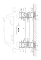
- FIG. 1 shows a schematic view schematically showing a wireless power receiving system 1 according to an embodiment of the present invention using a cross section in the width direction of a wheel.
- the wireless power receiving system 1 is used for the mobile body 2 having the wheels 3 to receive electric power from the power transmission device 4 installed on the road surface.
- the wireless power receiving system 1 includes a power receiving device 5 and an in-vehicle device 6. At least a part of the power receiving device 5 is housed in the wheels 3 of the mobile body 2, and receives power supplied wirelessly from the power transmitting device 4 installed on the road surface.
- the in-vehicle device 6 is installed in the mobile body 2 and is connected to the power receiving device 5 so as to be energized.
- the power receiving device 5 wirelessly receives electric power from the power transmitting device 4 when the moving body 2 travels or stops on the road surface on which the power transmitting device 4 is installed.
- the power receiving device 5 transmits the received power to the in-vehicle device 6.
- the wireless power receiving system 1 may further include a control device 7.
- the control device 7 is communicably connected to the power receiving device 5 and the vehicle-mounted device 6 via an in-vehicle network such as CAN (Controller Area Network).
- the control device 7 can control the power receiving device 5 and the vehicle-mounted device 6 to transmit the electric power received by the power receiving device 5 wirelessly to the vehicle-mounted device 6.
- the positions and numbers of the wheels 3, the power receiving device 5, the in-vehicle device 6, and the control device 7 in the moving body 2 shown in FIG. 1 are examples, and may be arbitrarily determined according to their uses and the like. it can.
- the moving body 2 can travel on a road surface such as a road by means of wheels 3.
- the moving body 2 is, for example, an automobile, but is not limited to this.
- the moving body 2 is provided with wheels 3 such as agricultural vehicles such as tractors, construction or construction vehicles such as dump trucks, airplanes, bicycles, and wheelchairs. Any vehicle capable of traveling can be included.
- the wheel 3 is used for moving the moving body 2.
- the wheel 3 has a ground contact surface in contact with a road surface such as a road in a state of being attached to the moving body 2.
- the wheel 3 is a tire / wheel assembly in which the tire 31 is mounted on the wheel 32, but the present invention is not limited to this, and any wheel that can be attached to the moving body 2 described above may be used.
- the "contact patch" of the wheel 3 means that when the wheel 3 is a tire / wheel assembly, the contact patch of the tire 31, that is, the tire 31 is mounted on the applicable rim, filled with the specified internal pressure, and loaded with the maximum load. The surface of the tire 31 in contact with the road surface in the state.
- the "applicable rim” is an industrial standard effective in the area where pneumatic tires are produced and used.
- JATMA Joint Automobile Tire Association
- JATMA YEAR BOOK and in Europe, ETRTO (ETRTO)
- ETRTO ETRTO
- STANDARDS MANUAL refers to Manufacturing Rim
- TRA's YEAR BOOK refers to Design Rim
- Applicable rims include sizes that may be included in the aforementioned industrial standards in the future in addition to current sizes.
- size described in the future the size described as “FUTURE DEVELOPMENTS” in the ETRTO 2013 edition can be mentioned.
- the "specified internal pressure” refers to the air pressure (maximum air pressure) corresponding to the maximum load capacity of a single wheel in the applicable size and ply rating described in the above-mentioned industrial standards such as JATMA YEAR BOOK. In the case of a size not described in the above-mentioned industrial standards, it means the air pressure (maximum air pressure) corresponding to the maximum load capacity specified for each vehicle equipped with tires. Further, in the present specification, the "maximum load” means a load corresponding to the maximum load capacity of a tire of an applicable size described in the above-mentioned industrial standard, or a size not described in the above-mentioned industrial standard. Means the load corresponding to the maximum load capacity specified for each vehicle equipped with tires.
- FIG. 1 shows a schematic view schematically showing a tire / wheel assembly as an example of a wheel 3 in a wireless power receiving system 1 according to an embodiment of the present invention, using a cross section in the width direction of the wheel 3. ing.
- the tire 31 has a pair of bead portions 311 and a pair of sidewall portions 312 and a tread portion 313.
- the bead portion 311 is configured such that when the tire 31 is attached to the rim portion 321 of the wheel 32, the inner side in the radial direction and the outer side in the width direction are in contact with the rim portion 321.
- the sidewall portion 312 extends between the tread portion 313 and the bead portion 311.
- the sidewall portion 312 is located radially outside the bead portion 311.
- the tread portion 313 is located radially outside the sidewall portion 312 and may include a contact patch of the tire 31.
- the tire 31 is made of rubber such as natural rubber and synthetic rubber, and may include parts made of metal such as steel such as carcass, belts and bead wires.
- metal such as steel
- carcass, belts and bead wires may be made of non-magnetic material.
- the tire 31 maintains the strength of the tire 31, and the metal exists between the power transmitting device 4 and the power receiving device 5, so that the power transmitting device 4 transfers the electromagnetic induction method to the power receiving device 5 as described later. It is possible to reduce the attenuation of the magnetic field generated by the power transmitting device 4 by the time it reaches the power receiving device 5 when the wireless power is supplied by the power transmitting device 4, and thus improve the power receiving efficiency of the power receiving device 5.
- at least a part of parts such as carcass, belt and bead wire may not be made of non-magnetic material.
- the non-magnetic material may include a paramagnetic material and a diamagnetic material having a small magnetic permeability.
- a resin material containing a thermoplastic resin such as polyester and nylon, a thermosetting resin such as vinyl ester resin and unsaturated polyester resin, and other synthetic resins can be used.
- the resin material can further contain fibers such as glass, carbon, graphite, aramid, polyethylene, and ceramic as reinforcing fibers.
- the non-magnetic material not only resin but also any non-metal material including rubber, glass, carbon, graphite, aramid, polyethylene, ceramic and the like can be used.
- a metal material containing a paramagnetic material such as aluminum or a diamagnetic material such as copper can be used.
- the wheel 32 has a cylindrical rim portion 321 for mounting the tire 31 and a disc portion 322 provided inside the rim portion 321 in the radial direction and supported and fixed to the hub 21 of the moving body 2. There is.
- the wheel 32 can be made of a metal such as steel, but is not limited to this. At least a part of the rim portion 321 of the wheel 32 may be formed of the non-magnetic material described above. As a result, while maintaining the strength of the wheel 32, the presence of a metal such as steel between the power transmitting device 4 and the power receiving device 5 causes the magnetic field generated by the power transmitting device 4 to reach the power receiving device 5. It is possible to reduce the attenuation and, by extension, improve the power receiving efficiency of the power receiving device 5. However, at least a part of the rim portion 321 of the wheel 32 does not have to be made of a non-magnetic material.
- the power transmission device 4 includes a power transmission coil (primary coil) 41.
- the power transmission device 4 is installed on a road surface such as a road or a parking lot.
- the power transmission device 4 is buried in a road or the like, but at least a part of the power transmission device 4 may be installed so as to be exposed on the road surface.
- the power transmission coil 41 is schematically shown for the sake of brevity.
- the power transmission coil 41 generates an alternating magnetic field based on the alternating current supplied from the power source.
- the power transmission coil 41 is formed in an annular shape as a whole.
- the plane surrounded by the annular power transmission coil 41 is also referred to as the coil surface of the power transmission coil 41.
- the coil surface of the power transmission coil 41 is substantially horizontal to the road surface (that is, the axial direction of the power transmission coil 41 is substantially perpendicular to the road surface so as to generate an alternating magnetic field upward of the road surface). (Like) are arranged.
- the power transmission coil 41 included in the power transmission device 4 is wound around a core such as a ferrite core to form an annular shape as a whole, but the whole is not limited to this, and an alternating magnetic field such as a coil spring or an air core coil can be generated. It may be any coil.
- a core such as a ferrite core
- an alternating magnetic field such as a coil spring or an air core coil
- It may be any coil.
- the power receiving device 5 includes a power receiving coil (secondary coil) 51.
- the power receiving coil 51 receives electric power wirelessly supplied from the power transmission coil 41 of the power transmission device 4.
- the power receiving coil 51 is formed in an annular shape as a whole.
- the plane surrounded by the annular power receiving coil 51 is also referred to as the coil surface of the power receiving coil 51.
- the power receiving coil 51 is arranged so that the coil surface of the power receiving coil 51 is substantially horizontal to the ground plane of the wheel 3 (that is, the axial direction of the power transmitting coil 41 is substantially perpendicular to the road surface).
- the power receiving coil 51 As a result, an electromotive force due to electromagnetic induction is generated in the power receiving coil 51 based on the alternating magnetic field generated by the power transmission coil 41, and a current flows through the power receiving coil 51.
- the power receiving coil 51 is schematically shown for the sake of brevity.
- At least a part of the power receiving coil 51 is housed in the wheel 3 of the moving body 2.
- at least a part (preferably all) of the coil surface of the power receiving coil 51 faces the ground plane of the wheel 3.
- the coil of the power receiving coil 51 At least a part of the surface can face at least a part of the coil surface of the transmission coil 41 with the ground contact surface of the wheel 3 interposed therebetween. Therefore, the possibility that an obstacle may enter between the power transmission coil 41 and the power reception coil 51 can be reduced, and the power reception coil 51 can appropriately receive the magnetic field lines emitted from the power transmission coil 41. Therefore, the power receiving efficiency in wireless power supply can be further improved.
- “at least a part of the surface A” is “opposed” to the surface B in a region extending in a direction perpendicular to the surface B in the range in which the surface B extends (at least a part of the surface A). In other words, it means that (at least a part of) surface A overlaps (in a columnar region) having surface B as a cross section.
- At least a part (preferably all) of the ground contact surface of the wheel 3 faces the coil surface of the power receiving coil 51.
- at least a part (preferably all) of the coil surface of the power receiving coil 51 faces the ground plane of the wheel 3 and / or the wheel 3 as in the present embodiment. It is preferable that at least a part (preferably all) of the ground plane of the power receiving coil 51 faces the coil surface of the power receiving coil 51.
- the power receiving coil 51 of the power receiving device 5 is housed in the wheel 3 of the moving body 2 so as not to rotate together with the wheel 3.
- the power receiving coil 51 may be installed in a portion of the moving body 2 such as a cover 21a of the hub 21 that is attached to the wheel 3 from the radial inside of the wheel 3.
- at least a part of the power receiving coil 51 is accommodated inside the wheel 32 in the radial direction in a state where the wheel 32 of the wheel 3 is attached to the hub 21 of the moving body 2.
- the power receiving device 5 may further include a power conversion unit, a power storage unit, a measuring unit, and the like in addition to the power receiving coil 51.
- the power conversion unit is equipped with a converter that converts AC power into DC power, an inverter that converts DC power into AC power, and the like.
- the power storage unit stores the electric power generated in the power receiving coil 51.
- the power storage unit can be, for example, a capacitor. When the power storage unit is a capacitor, it can be charged and discharged in a shorter time than a storage battery or the like, which is advantageous in a situation where high responsiveness is required.
- the measuring unit measures the strength of the electric power received by the power receiving device 5.
- the measuring unit is, for example, a voltmeter or an ammeter, but is not limited thereto.
- the intensity of electric power measured by the measuring unit may include arbitrary numerical information such as electric power, electric energy, voltage, current, magnetic flux, or magnetic flux density.
- the power receiving device 5 includes a power receiving coil 51 and a coil case 55.
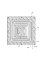
- FIG. 2 is a plan view of the power receiving coil 51 as viewed from a direction orthogonal to the coil surface.
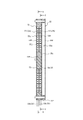
- FIG. 3 is a cross-sectional view taken along the line AA of the power receiving coil 51 and the coil case 55 of FIG.
- FIG. 4 is a cross-sectional view of the power receiving coil 51 and the coil case 55 on the line BB of FIG. 3
- FIG. 5 is a cross-sectional view of the power receiving coil 51 and the coil case 55 on the line CC of FIG. FIG.
- FIG. 6 is a perspective view schematically showing the winding structure of the wire rod 53 constituting the power receiving coil 51.
- the wire rod 53 is omitted so that the shapes of the spiral grooves 55g and 55h can be easily understood.
- the first spiral coil layer 52a is shown by a broken line
- the second spiral coil layer 52b is shown by a solid line.
- the power receiving coil 51 can have a multi-layer structure having a plurality of laminated spiral coil layers 52a and 52b.
- the power receiving coil 51 shown in FIGS. 2 to 6 has a two-layer structure having a laminated first spiral coil layer 52a and a second spiral coil layer 52b.
- the power receiving coil 51 is arranged so that the first spiral coil layer 52a faces the power transmission coil 41.
- the first spiral coil layer 52a is located below the second spiral coil layer 52b in the vertical direction.
- the power receiving coil 51 may have three or more laminated spiral coil layers.
- the first spiral coil layer 52a and the second spiral coil layer 52b are arranged so as to be overlapped so that their central axes are located on the same straight line.
- the spiral coil layers 52a and 52b are formed by winding the wire rod 53 on the same surface (on the same plane in this example) in a spiral shape (spiral shape).
- the direction in which the central axes of the spiral coil layers 52a and 52b around which the wire rod 53 is wound extend is defined as the axial direction of the power receiving coil 51.
- the wire rod 53 constituting each of the spiral coil layers 52a and 52b is continuous as a whole.
- the wire rod 53 constituting the first spiral coil layer 52a and the wire rod 53 constituting the second spiral coil layer 52b are continuous at the inner peripheral edges of the spiral coil layers 52a and 52b, respectively. That is, the connecting portion 54 between the first spiral coil layer 52a and the second spiral coil layer 52b is located at the inner peripheral edge portion of the power receiving coil 51 (the inner peripheral edge portion of each of the spiral coil layers 52a and 52b).
- the wire rod 53 constituting the first spiral coil layer 52a and the wire rod 53 constituting the second spiral coil layer 52b do not have to be continuous at the inner peripheral edges of the spiral coil layers 52a and 52b.
- the position of the connecting portion 54 is not limited to the inner peripheral edge portion of the power receiving coil 51, and may be provided, for example, on the outer peripheral edge portion of the power receiving coil 51.
- the wire rod 53 constituting the first spiral coil layer 52a and the wire rod 53 constituting the second spiral coil layer 52b may be connected at the connecting portion 54 by welding, pressure welding, or the like, or as described later, the connecting portion.
- the first spiral coil layer 52a including the 54 and the second spiral coil layer 52b may be wound by one continuous wire rod 53.
- the connecting portion 54 is preferably inclined with respect to the axial direction of the power receiving coil 51, but may be parallel to the axial direction of the power receiving coil 51 (perpendicular to the coil surface of the power receiving coil 51). In this example, the connecting portion 54 is gently inclined in the thickness direction of the power receiving coil 51. Specifically, the connecting portion 54 intersects the wire rod 53 constituting the first spiral coil layer 52a and the wire rod 53 forming the second spiral coil layer 52b at an obtuse angle (angle of more than 90 ° and less than 180 °). It is inclined like.
- the first spiral coil layer 52a and the second spiral coil layer 52b are configured by winding one continuous wire rod 53. That is, the first spiral coil layer 52a and the second spiral coil layer 52b, including the connecting portion 54, are composed of one continuous wire rod 53.
- “one continuous wire rod 53” means a wire rod integrally formed as a whole, and includes, for example, a litz wire composed of a plurality of twisted enamel wires and the like. Further, the wire rod 53 is preferably a litz wire, but is not limited to this, and may be, for example, a single wire.
- the wire rod 53 constituting the power receiving coil 51 is substantially quadrangular as a whole from the winding start end portion (one end portion 53a of the wire rod 53) located on the outer peripheral edge side of the first spiral coil layer 52a. It extends spirally inward in the radial direction so as to form a (more specifically, substantially square) coil surface, and is connected to a connecting portion 54 that is inclined with respect to the coil surface at the inner peripheral edge portion, and the connection thereof. The portion 54 smoothly connects to the inner peripheral edge portion of the second spiral coil layer 52b.
- the wire rod 53 extends radially outward from the inner peripheral edge portion of the second spiral coil layer 52b in the same manner as the first spiral coil layer 52a, and ends at the end of winding (wire rod) toward the outer peripheral edge portion.
- the other end 53b) of 53 is located.
- One end 53a and the other end 53b of the wire rod 53 are arranged on the same side surface 55f of the quadrangular plate-shaped coil case 55, which will be described later. Further, one end 53a and the other end 53b of the wire rod 53 are located near both ends in the longitudinal direction of the side surface 55f, respectively. With such a configuration, the one end portion 53a and the other end portion 53b can be arranged at a more distant position.
- the power receiving device 5 includes a coil case 55 that supports the wire rod 53.
- the coil case 55 has a resin case body 55a (wire support portion) made of an insulating material, a first cover 55b that covers the front surface of the case body 55a, and a second cover 55c that covers the back surface of the case body 55a. ..
- the first cover 55b and the second cover 55c are made of a resin made of an insulating material.
- the coil case 55 of this example has a third cover 55d provided on the outside (back side) of the second cover 55c.
- the third cover 55d may be made of resin or a metal such as aluminum.
- the first spiral coil layer 52a is held between the case body 55a and the first cover 55b, and the second spiral coil layer 52b is held between the case body 55a and the second cover 55c.
- the wire rod 53 constituting the power receiving coil 51 is housed in the coil case 55 except for the end portions 53a and 53b on both sides. As a result, it is possible to suppress the adhesion of dust and the like to the wire rod 53.
- the case body 55a, the first cover 55b, the second cover 55c, and the third cover 55d constituting the coil case 55 are fixed to each other by fastening with a fastening member such as a screw, or by adhesion or welding.
- the coil case 55 has a space 55e in which a plate-shaped magnetic material (ferrite member) or the like can be arranged between the second cover 55c and the third cover 55d.
- a magnetic material such as a ferrite core may be provided inside (center axis side) of the inner peripheral edge of the power receiving coil 51.
- a space for arranging the magnetic material can be provided in the central portion of the case body 55a.
- the coil case 55 is formed in a flat plate shape as a whole. Further, the coil case 55 has a square shape, more specifically, a substantially square shape in a plan view when viewed from the axial direction of the power receiving coil 51. However, it may have a different shape in the same plan view. Further, the case body 55a, the first cover 55b, the second cover 55c, and the third cover 55d constituting the coil case 55 also have a quadrangular plate shape in a plan view, and are overlapped in the thickness direction of the coil case 55. Have been placed.
- the coil case 55 is not limited to a flat one as in this example, and may be curved, bent, or having a concave portion or a convex portion.
- Spiral grooves 55g and 55h are formed on the front surface and the back surface of the case body 55a, respectively, and the wire rod 53 is arranged along the spiral grooves 55g and 55h, respectively.
- the wire rod 53 arranged along the spiral groove 55g on the surface of the case body 55a constitutes the first spiral coil layer 52a, and the wire rod 53 arranged along the spiral groove 55h on the back surface of the case body 55a is the second.
- the spiral coil layer 52b is formed.
- a partition wall 55j is provided between the spiral groove 55g on the front surface of the case body 55a and the spiral groove 55h on the back surface.
- the spiral groove 55g on the front surface of the case body 55a and the spiral groove 55h on the back surface are separated by a partition wall 55j in a predetermined distance (at least the thickness of the partition wall 55j or more) in the thickness direction of the case body 55a (axial direction of the power receiving coil 51). ) Is separated. Further, the spiral groove 55g on the front surface and the spiral groove 55h on the back surface communicate with each other through the through hole 55k formed in the partition wall 55j. The through hole 55k penetrates from the groove bottom of the spiral groove 55g on the front surface (the surface of the partition wall 55j) to the groove bottom of the spiral groove 55h on the back surface (the back surface of the partition wall 55j).
- the through hole 55k is formed at a position corresponding to the connecting portion 54 of the power receiving coil 51. Therefore, the position of the through hole 55k can be appropriately changed according to the position of the connecting portion 54 of the power receiving coil 51.
- the through hole 55k is located at the center of the case body 55a, and more specifically, at a position corresponding to the inner peripheral edge of the power receiving coil 51. As a result, the connecting portion 54 of the power receiving coil 51 can be arranged in the through hole 55k.
- the in-vehicle device 6 is installed in the mobile body 2 and is connected to the power receiving device 5 so as to be energized.
- the power receiving device 5 and the in-vehicle device 6 may be connected by wire so as to be energized.
- the power transmission efficiency from the power receiving device 5 to the in-vehicle device 6 is improved as compared with the case where the power receiving device 5 is connected wirelessly.
- the power receiving device 5 and the in-vehicle device 6 may be wirelessly connected so as to be energized.
- the in-vehicle device 6 may include, for example, a drive device 61 that drives the wheels 3 by electric power.
- the drive device 61 consumes the electric power supplied from the power receiving device 5 to drive the wheels 3.
- the drive device 61 is an in-wheel motor in which at least a part thereof is housed in the wheel 3, but the drive device 61 is not limited to this.
- the drive device 61 may be an on-board motor mounted on the main body of the moving body 2 and driving the wheels 3 by driving the shaft 22 of the moving body 2.
- the in-vehicle device 6 may include a power storage device 62 for storing electric power.
- the power storage device 62 can store the electric power supplied from the power receiving device 5 and supply the electric power to the other in-vehicle device 6.
- the power storage device 62 may be, for example, an arbitrary storage battery such as a lead storage battery, a nickel hydrogen storage battery, a lithium ion battery, a sodium sulfur battery, or a combination thereof.
- the in-vehicle device 6 is not limited to the above-mentioned example, and may include any electronic device installed in the mobile body 2, such as a communication device of the mobile body 2, a car navigation system, a media player, and an in-vehicle sensor. Good.
- the in-vehicle device 6 may be installed integrally with the moving body 2 or may be detachably installed.
- the control device 7 controls at least one of the power receiving device 5 and the in-vehicle device 6.
- the control device 7 is, for example, a control device (ECU: Electronic Control Unit), but is not limited to this, and may be any electronic device.
- the control device 7 may be connected to the power receiving device 5 so as to be energized as one of the in-vehicle devices 6 described above.
- the control device 7 may include, for example, a control unit, a storage unit, a communication unit, an output unit, an input unit, and the like.
- the control device 7 receives, for example, the electric power received by the power receiving device 5 wirelessly from the power receiving device 5 based on a predetermined condition, for example, at least one of a plurality of in-vehicle devices 6 including a driving device 61 and a power storage device 62. Can be transmitted to.
- the wireless power receiving system 1 has a power receiving coil 51 that receives power wirelessly supplied from the power transmission coil 41 of the power transmission device 4 installed on the road surface, and receives power.
- a power receiving device 5 in which at least a part of the coil 51 is housed in the wheels 3 of the moving body 2 and an in-vehicle device 6 installed in the moving body 2 and electrically connected to the power receiving device 5 are provided to receive power.
- the device 5 can transmit the received electric power to the in-vehicle device 6, and the power receiving coil 51 has a plurality of stacked spiral coil layers 52a and 52b.
- the wireless power receiving system 1 can improve the power receiving efficiency in wireless power supply.
- the power receiving coil 51 has a plurality of laminated spiral coil layers 52a and 52b, so that the power receiving coil 51 has a single layer structure having the same power receiving performance.
- the area of the coil surface can be made smaller than that of a coil (a power receiving coil composed of only one spiral coil layer). That is, the area of the coil surface of the power receiving coil 51 can be suppressed while ensuring the number of turns of the power receiving coil 51 as a whole and the power receiving performance by the plurality of spiral coil layers 52a and 52b. Therefore, the degree of freedom in the installation range of the power receiving coil 51 is improved, and the power receiving coil 51 can be accommodated in a wide range of the wheels 3. Further, since the area of the coil surface can be reduced, it becomes easy to install the coil surface at a position close to the power transmission coil 41. Therefore, the power receiving efficiency of the power receiving device 5 can be further improved.
- the power receiving coil 51 has a two-layer structure having a first spiral coil layer 52a and a second spiral coil layer 52b. According to such a configuration, the winding structure of the wire rod is less likely to be complicated than in the case of providing three or more spiral coil layers, so that the power receiving coil 51 can be easily manufactured.
- the wire rod 53 constituting the first spiral coil layer 52a and the wire rod 53 forming the second spiral coil layer 52b are continuous at the inner peripheral edge portion of the power receiving coil 51. ing. According to such a configuration, it is possible to prevent the configuration of the power receiving device 5 from becoming complicated as compared with the case where the first spiral coil layer 52a and the second spiral coil layer 52b are independent of each other, and the entire power receiving device 5 can be used. It can be a simple configuration. Further, since the connecting portion 54 is provided on the inner peripheral edge portion of the power receiving coil 51, both end portions 53a and 53b of the wire rod 53 of the power receiving coil 51 can be easily arranged at a distance from each other. Therefore, since the distance between the wire rods 53 can be appropriately secured, the loss due to the proximity effect can be reduced. As a result, the power receiving efficiency of the power receiving device 5 can be further improved.
- the wire rod 53 constituting the first spiral coil layer 52a and the wire rod 53 constituting the second spiral coil layer 52b are composed of one continuous wire rod 53. There is. According to such a configuration, the power transmission loss can be reduced as compared with the case where a plurality of wire rods 53 are connected to form the power receiving coil 51. Further, since it is not necessary to connect a plurality of wire rods 53, the power receiving coil 51 can be easily manufactured.
- the power receiving coil 51 includes a plate-shaped case body 55a (wire support portion) made of an insulating material, and spiral grooves 55g, 55h formed in the case body 55a.
- the wire rod 53 is arranged along the above. According to such a configuration, the wire rod 53 constituting the power receiving coil 51 can be held in a stable state. Further, since the distance between the wire rods 53 constituting the power receiving coil 51 can be appropriately secured, the loss due to the proximity effect can be reduced. As a result, the power receiving efficiency of the power receiving device 5 can be further improved.
- spiral grooves 55g and 55h are formed on the front surface and the back surface of the case body 55a, respectively, and the spiral grooves 55g formed on the front surface and the spiral groove 55g are formed on the back surface, respectively.
- the spiral groove 55h communicates with the through hole 55k formed in the case body 55a.
- a plurality of spiral coil layers 52a and 52b laminated by arranging the wire rod 53 along the spiral groove 55g on the front surface of the case body 55a and the spiral groove 55h on the back surface can be easily formed. Can be done.
- the first spiral coil layer 52a on the front surface side of the case body 55a and the second spiral coil layer 52b on the back surface side can be easily made continuous.
- the moving body 2 has a wheel 3 and a power receiving coil 51 that receives electric power wirelessly supplied from a power transmission coil 41 of a power transmission device 4 installed on a road surface.
- a power receiving device 5 having at least a part housed in the wheels 3 and an in-vehicle device 6 connected to the power receiving device 5 so as to be energized are provided, and the power receiving device 5 can transmit the received power to the in-vehicle device 6.
- the power receiving coil 51 has a plurality of laminated spiral coil layers 52a and 52b.
- the mobile body 2 can improve the power receiving efficiency in wireless power supply.
- the power receiving coil 51 has a plurality of laminated spiral coil layers 52a and 52b, the coil surface seen from the axial direction of the power receiving coil 51 is compared with the power receiving coil having a single layer structure having the same power receiving performance. The area of can be reduced. Therefore, the degree of freedom in the installation range of the power receiving coil 51 is improved, and the power receiving coil 51 can be accommodated in a wide range of the wheels 3. Further, since it is easy to install the power transmission coil 41 at a position close to the power transmission coil 41, the power reception efficiency of the power reception device 5 can be further improved.
- the wheel 3 is the wheel 3 of the moving body 2 and has a power receiving coil 51 that receives power wirelessly supplied from the power transmission coil 41 of the power transmission device 4 installed on the road surface.
- the device 5 is provided, and at least a part of the power receiving coil 51 is housed therein, and the power receiving coil 51 has a plurality of laminated spiral coil layers 52a and 52b.
- at least a part of the power receiving coil 51 is housed in the wheel 3 that is in direct contact with the road surface, so that an obstacle is created in the space between the power transmitting coil 41 and the power receiving coil 51 provided on the road surface. The risk of entry can be reduced. Therefore, the wheel 3 can improve the power receiving efficiency in wireless power supply.
- the power receiving coil 51 has a plurality of laminated spiral coil layers 52a and 52b, the coil surface seen from the axial direction of the power receiving coil 51 is compared with the power receiving coil having a single layer structure having the same power receiving performance. The area of can be reduced. Therefore, the degree of freedom in the installation range of the power receiving coil 51 is improved, and the power receiving coil 51 can be accommodated in a wide range of the wheels 3. Further, since it is easy to install the power transmission coil 41 at a position close to the power transmission coil 41, the power reception efficiency of the power reception device 5 can be further improved.
- FIG. 7 is a schematic view schematically showing a tire / wheel assembly as an example of the wheel 3 in the wireless power receiving system 1 by using a cross section in the width direction of the wheel 3.
- FIG. 8 is a schematic view schematically showing a converter 56a and an inverter 56b of the power receiving device 5 housed in the wheel 3 of FIG. 7.
- the drive device 61 is an in-wheel motor installed on the wheel 3, and at least a part thereof is housed in the wheel 3.
- the power receiving device 5 includes a converter 56a and an inverter 56b as a power conversion unit.
- the converter 56a is connected to the power receiving coil 51 and the inverter 56b.
- the converter 56a can convert the AC power generated in the power receiving coil 51 into DC power and transmit it to the inverter 56b.
- the inverter 56b is connected to the converter 56a and the drive device 61.
- the inverter 56b can convert the DC power from the converter 56a into AC power and transmit it to the drive device 61.
- the converter 56a is located vertically above the power receiving coil 51, and the inverter 56b is located vertically above the converter 56a.
- the entire converter 56a and the entire inverter 56b are housed in the wheels 3. It is sufficient that at least a part of the converter 56a and the inverter 56b is housed in the wheel 3.
- the converter 56a and the inverter 56b are provided on the annular substrate 56c coaxially arranged with the wheel 3.
- the power receiving coil 51 is located below the substrate 56c.
- the power receiving coil 51 may be located at a position where it overlaps the substrate 56c in the vertical direction.
- the converter 56a and the inverter 56b are arranged at different circumferential positions on the annular substrate 56c.
- the converter 56a and the inverter 56b are arranged concentrically on the substrate 56c.
- the converter 56a is located below the substrate 56c and the inverter 56b is located above the substrate 56c.
- the drive device 61 is a direct drive motor 63 coaxially arranged with the wheels 3.
- the direct drive motor 63 is coaxially arranged with the wheels 3. Further, the entire direct drive motor 63 is housed in the wheel 3. It is sufficient that at least a part of the direct drive motor 63 is housed in the wheel 3.
- the power receiving device 5 has a coil case 55 accommodating 51 power receiving coils.
- the coil case 55 is provided integrally with the case 56d that houses the converter 56a.
- the coil case 55 may be connected to the case 56d. Further, the coil case 55 may be installed independently of the case 56d accommodating the converter 56a.
- the entire case 56d is housed in the wheel 3.
- the case 56d surrounds the substrate 56c, the converter 56a, the inverter 56b, and the direct drive motor 63 from the outside.
- the case 56d accommodating the converter 56a is not an essential configuration.
- the wireless power receiving system 1 having the form shown in FIGS. 7 and 8 has a power receiving coil 51 that receives electric power supplied wirelessly from the power transmitting coil 41 of the power transmitting device 4 installed on the road surface.
- a power receiving device 5 in which at least a part of the power receiving coil 51 is housed in the wheels 3 of the moving body 2 and a driving device 61 installed on the wheels 3 and driving the wheels 3 with the electric power received by the power receiving device 5 are provided.
- the power receiving device 5 includes a converter 56a that converts AC power generated in the power receiving coil 51 into DC power, and an inverter 56b that can convert DC power from the converter 56a into AC power and transmit it to the drive device 61.
- At least a part of the converter 56a and at least a part of the inverter 56b are housed in the wheels 3, the converter 56a is located vertically above the power receiving coil 51, and the inverter 56b is vertically above the converter 56a. Located in. According to this configuration, at least a part of the power receiving coil 51 is housed in the wheel 3 that is in direct contact with the road surface, so that an obstacle is created in the space between the power transmitting coil 41 and the power receiving coil 51 provided on the road surface. The risk of entry can be reduced. Therefore, the wireless power receiving system 1 can improve the power receiving efficiency in wireless power supply.
- the converter 56a is located vertically above the power receiving coil 51, and the inverter 56b is located vertically above the converter 56a.
- the power receiving coil 51 can be easily arranged in the vicinity of the power transmitting coil 41, and the power supply from the power transmitting coil 41 to the power receiving coil 51 is less likely to be obstructed by the inverter 56b and the converter 56a. Therefore, the power receiving efficiency can be improved.
- the power receiving coil 51 and the converter 56a are easily arranged close to each other, it is possible to reduce the power transmission loss when the power receiving coil 51 transmits power to the converter 56a. Further, it is easy to shorten the power transmission path from the power receiving coil 51 to the drive device 61 via the converter 56a and the inverter 56b. Therefore, the transmission loss can be reduced, and the space in the wheel 3 can be effectively utilized.
- the converter 56a and the inverter 56b are provided on the annular substrate 56c coaxially arranged on the wheel 3. According to such a configuration, the converter 56a and the inverter 56b can be efficiently installed around the shaft portion of the wheel 3, and the space in the wheel 3 can be effectively utilized.
- the drive device 61 is a direct drive motor 63 coaxially arranged with the wheels 3. According to this configuration, the rotational force of the direct drive motor 63 can be directly transmitted to the wheel 3 without going through an indirect mechanism (gearbox or the like), so that the loss of power is reduced and the wheel is efficiently used. 3 can be driven.
- the power receiving device 5 has a coil case 55 accommodating the power receiving coil 51, and the coil case 55 is integrated with the case 56d accommodating the converter 56a, or is a case. It is connected to 56d. According to such a configuration, the positional relationship between the power receiving coil 51 and the converter 56a can be easily stabilized. Further, by integrating the coil case 55 and the case 56d accommodating the converter 56a, the power receiving device 5 can be easily miniaturized.
- the moving body 2 having the form shown in FIGS. 7 and 8 has a wheel 3 and a power receiving coil 51 that receives electric power wirelessly supplied from the power transmitting coil 41 of the power transmitting device 4 installed on the road surface.
- the power receiving device 5 includes a power receiving device 5 in which at least a part of the above is housed in the wheels 3 and a driving device 61 installed on the wheels 3 for driving the wheels 3 with the electric power received by the power receiving device 5.
- a converter 56a that converts AC power generated in the coil 51 into DC power, and an inverter 56b that can convert DC power from the converter 56a into AC power and transmit it to the drive device 61 are provided, and at least a part of the converter 56a and At least a part of the inverter 56b is housed in the wheel 3, the converter 56a is located vertically above the power receiving coil 51, and the inverter 56b is located vertically above the converter 56a.
- at least a part of the power receiving coil 51 is housed in the wheel 3 that is in direct contact with the road surface, so that an obstacle is created in the space between the power transmitting coil 41 and the power receiving coil 51 provided on the road surface. The risk of entry can be reduced.
- the wireless power receiving system 1 can improve the power receiving efficiency in wireless power supply. Further, since the converter 56a is located vertically above the power receiving coil 51 and the inverter 56b is located vertically above the converter 56a, the power receiving coil 51 can be easily arranged close to the power transmitting coil 41, and the power receiving coil 51 can be easily arranged. The power supply from the transmission coil 41 to the power receiving coil 51 is less likely to be obstructed by the inverter 56b and the converter 56a. Therefore, the power receiving efficiency can be improved. Further, since the power receiving coil 51 and the converter 56a are easily arranged close to each other, it is possible to reduce the power transmission loss when the power receiving coil 51 transmits power to the converter 56a. Further, it is easy to shorten the power transmission path from the power receiving coil 51 to the drive device 61 via the converter 56a and the inverter 56b. Therefore, the transmission loss can be reduced, and the space in the wheel 3 can be effectively utilized.
- the wheel 3 having the form shown in FIGS. 7 and 8 is the wheel 3 of the moving body 2 and has a power receiving coil 51 that receives electric power wirelessly supplied from the power transmitting coil 41 of the power transmitting device 4 installed on the road surface.
- the power receiving device 5 includes a power receiving device 5 and a driving device 61 that drives the wheels 3 with the power received by the power receiving device 5.
- the power receiving device 5 includes a converter 56a that converts AC power generated in the power receiving coil 51 into DC power, and a converter.
- the inverter 56b capable of converting the DC power from the 56a into AC power and transmitting the DC power to the drive device 61 is provided, and the wheel 3 houses at least a part of the converter 56a and at least a part of the inverter 56b inside.
- the 56a is located vertically above the power receiving coil 51, and the inverter 56b is located vertically above the converter 56a.
- the wireless power receiving system 1 can improve the power receiving efficiency in wireless power supply.
- the converter 56a is located vertically above the power receiving coil 51 and the inverter 56b is located vertically above the converter 56a, the power receiving coil 51 can be easily arranged close to the power transmitting coil 41, and the power receiving coil 51 can be easily arranged.
- the power supply from the transmission coil 41 to the power receiving coil 51 is less likely to be obstructed by the inverter 56b and the converter 56a. Therefore, the power receiving efficiency can be improved. Further, since the power receiving coil 51 and the converter 56a are easily arranged close to each other, it is possible to reduce the power transmission loss when the power receiving coil 51 transmits power to the converter 56a. Further, it is easy to shorten the power transmission path from the power receiving coil 51 to the drive device 61 via the converter 56a and the inverter 56b. Therefore, the transmission loss can be reduced, and the space in the wheel 3 can be effectively utilized.
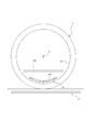
- the power receiving coil 51 shown in FIG. 9 has a downwardly convex shape when viewed from the side of the wheel 3 in the axial direction.
- FIG. 9 only the wheel 3 and the power receiving coil 51 are schematically shown.
- a power receiving coil 51a having a flat shape extending in the horizontal direction when viewed from the axial direction of the wheel 3 is shown by a chain double-dashed line.
- a power receiving coil 51b having a bent shape that is convex downward in a side view is shown by a chain double-dashed line.
- the power receiving coil 51b has the same width and height as the power receiving coil 51 when viewed from the side.
- the power receiving coil 51 shown in FIG. 9 has a single-layer structure composed of one spiral coil layer, but is not limited to this.
- the power receiving coil 51 shown in FIG. 9 is curved in an arc shape as a whole when viewed from the side.
- the power receiving coil 51 is not limited to a shape that is curved in an arc shape, and may be at least a non-flat shape that is convex downward as a whole.
- the power receiving coil 51 may be configured to be bent downward in a V shape like the power receiving coil 51b.
- the power receiving device 5 may have a coil case having a curved shape corresponding to the shape of the power receiving coil 51.
- the center of curvature P of the power receiving coil 51 in a side view is located on the central axis of the wheel 3.
- the power receiving coil 51 can be arranged along the inner peripheral surface 3a of the wheel 3.
- the inner peripheral surface 3a of the wheel 3 can be, for example, the inner peripheral surface of the rim portion 321 but is not limited to this.
- the power receiving coil 51 shown in FIG. 10 has a plurality of laminated spiral coil layers 52c and 52d.
- FIG. 10 only the wheel 3 and the power receiving coil 51 are schematically shown.
- a power receiving coil 51c having a single layer structure composed of one spiral coil layer is shown by a chain double-dashed line.
- the power receiving coil 51 has a laminated structure having a plurality of spiral coil layers 52c and 52d, and the length in the wheel circumferential direction is reduced to receive power with the power transmission coil 41 installed on the road surface. The average distance from the coil 51 can be reduced.
- the center of curvature P of the power receiving coil 51 in a side view is located on the central axis of the wheel 3, but the present invention is not limited to this.
- the power receiving coil 51 of FIG. 10 is composed of two spiral coil layers 52c and 52d, it may have three or more spiral coil layers.
- the power receiving coil 51 shown in FIG. 10 can have the same configuration as the power receiving coil 51 having a laminated structure described with reference to FIGS. 2 to 6 except that the power receiving coil 51 is curved in a side view.
- the two spiral coil layers 52c and 52d may be formed by being wound around one continuous wire rod 53.
- the power receiving device 5 can include a coil case 55 having a curved shape corresponding to the power receiving coil 51.
- the coil case 55 may include a curved case body 55a (wire support portion) corresponding to the shape of the power receiving coil 51, a first cover 55b, a second cover 55c, a third cover 55d, and the like. ..
- the two spiral coil layers 52c and 52d may be formed by arranging the wire rod 53 along the spiral grooves provided on the front surface and the back surface of the case body 55a.
- the wireless power receiving system 1 having the form shown in FIGS. 9 and 10 has a power receiving coil 51 that receives electric power supplied wirelessly from the power transmission coil 41 of the power transmission device 4 installed on the road surface. It includes a power receiving device 5 in which at least a part of the power receiving coil 51 is housed in the wheels 3 of the moving body 2, and an in-vehicle device 6 installed in the moving body 2 and connected to the power receiving device 5 so as to be energized.
- the power receiving device 5 can transmit the received power to the in-vehicle device 6, and the power receiving coil 51 has a downward convex shape when viewed from the axial direction of the wheel 3.
- the wireless power receiving system 1 can improve the power receiving efficiency in wireless power supply.
- the power receiving coil 51 has a downwardly convex shape when viewed from the axial direction of the wheel 3, so that the power receiving coil 51 is laterally viewed from the side.
- the average distance between the power transmitting coil 41 installed on the road surface and the power receiving coil 51 can be made smaller than that of the extending flat power receiving coil 51a. As a result, the power supply efficiency of the wireless power receiving system 1 having the power receiving coil 51 can be improved.
- the power receiving coil 51 is curved in an arc shape in a side view. According to such a configuration, the average distance between the power transmitting coil 41 and the power receiving coil 51 can be further reduced as compared with, for example, a V-shaped bent power receiving coil 51b having the same width and the same height in the side view. The power supply efficiency of the wireless power receiving system 1 can be further improved.
- the center of curvature P of the power receiving coil 51 in the side view is located on the central axis of the wheel 3. According to such a configuration, since the power receiving coil 51 can be arranged along the inner peripheral surface 3a of the wheel 3, the average distance between the power transmitting coil 41 and the power receiving coil 51 can be further reduced, and the wireless power receiving system 1 Power supply efficiency can be further improved. Further, by arranging the power receiving coil 51 along the inner peripheral surface 3a of the wheel 3, the space inside the wheel 3 can be effectively utilized.
- the power receiving coil 51 has a plurality of laminated spiral coil layers 52c and 52d. According to such a configuration, the length of the power receiving coil 51 in the circumferential direction in the side view can be made smaller than that of the power receiving coil 51c having a single layer structure composed of one spiral coil layer. Therefore, the average distance between the power transmission coil 41 and the power reception coil 51 installed on the road surface can be further reduced, and the power supply efficiency can be further improved.
- the moving body 2 having the form shown in FIGS. 9 and 10 has a wheel 3 and a power receiving coil 51 that receives electric power wirelessly supplied from a power transmission coil 41 of a power transmission device 4 installed on a road surface.
- a power receiving device 5 in which at least a part of the power is housed in the wheels 3 and an in-vehicle device 6 which is electrically connected to the power receiving device 5 are provided, and the power receiving device 5 transmits the received power to the in-vehicle device 6. It is possible, and the power receiving coil 51 has a downwardly convex shape when viewed from the side of the wheel 3 in the axial direction.
- the mobile body 2 can improve the power receiving efficiency in wireless power supply.
- the power receiving coil 51 since the power receiving coil 51 has a downwardly convex shape in the side view from the axial direction of the wheel 3, it is installed on the road surface as compared with the flat shape power receiving coil 51a extending in the horizontal direction in the side view. The average distance between the power transmission coil 41 and the power reception coil 51 can be reduced. As a result, the power supply efficiency of the wireless power receiving system 1 having the power receiving coil 51 can be improved.
- the wheel 3 having the form shown in FIGS. 9 and 10 is the wheel 3 of the moving body 2 and has a power receiving coil 51 that receives power wirelessly supplied from the power transmission coil 41 of the power transmission device 4 installed on the road surface.
- the power receiving device 5 is provided, and at least a part of the power receiving coil 51 is housed therein, and the power receiving coil 51 has a downward convex shape when viewed from the axial direction of the wheel 3.
- at least a part of the power receiving coil 51 is housed in the wheel 3 that is in direct contact with the road surface, so that an obstacle is created in the space between the power transmitting coil 41 and the power receiving coil 51 provided on the road surface. The risk of entry can be reduced.
- the wheel 3 can improve the power receiving efficiency in wireless power supply.
- the power receiving coil 51 has a downwardly convex shape in the side view from the axial direction of the wheel 3, it is installed on the road surface as compared with the flat shape power receiving coil 51a extending in the horizontal direction in the side view.
- the average distance between the power transmission coil 41 and the power reception coil 51 can be reduced.
- the power supply efficiency of the wireless power receiving system 1 having the power receiving coil 51 can be improved.
- all or a part of the functions or processes described as the functions or processes of the control device 7 may be realized as the functions or processes of the power receiving device 5 or the in-vehicle device 6.
- a program describing processing contents for realizing each function of the control device 7 according to the embodiment is stored in a memory or the like provided in the power receiving device 5 or the in-vehicle device 6, and the processor or the like of the power receiving device 5 or the in-vehicle device 6 is used to store the program.
- the program may be read and executed.
- the coil surface of the power receiving coil 51 has been described as being arranged so as to be substantially parallel to the ground plane of the wheel 3, but this is not the case.
- the coil surface of the power receiving coil 51 may be arranged at an arbitrary angle of 0 to 90 degrees with the ground contact surface of the wheel 3.
- the angle between the coil surface of the power receiving coil 51 and the ground plane of the wheel 3 may be arbitrarily determined according to the application of the power receiving device 5, the amount of power to be received, and the like.
- the tire 31 has been described as being filled with air, but this is not the case.
- the tire 31 can be filled with a gas such as nitrogen.
- the tire 31 can be filled with an arbitrary fluid including a liquid, a gel-like substance, a powder or granular material, or the like, in place of or in addition to the gas.
Landscapes
- Engineering & Computer Science (AREA)
- Power Engineering (AREA)
- Computer Networks & Wireless Communication (AREA)
- Transportation (AREA)
- Mechanical Engineering (AREA)
- Life Sciences & Earth Sciences (AREA)
- Sustainable Development (AREA)
- Sustainable Energy (AREA)
- Electric Propulsion And Braking For Vehicles (AREA)
- Current-Collector Devices For Electrically Propelled Vehicles (AREA)
- Charge And Discharge Circuits For Batteries Or The Like (AREA)
Abstract
無線受電システム1は、路面に設置された送電装置4の送電コイル41から無線により供給される電力を受電する受電コイル51を有し、受電コイル51の少なくとも一部が移動体2の車輪3に収容された、受電装置5と、移動体2に設置され、受電装置5と通電可能に接続された、車載装置6と、を備え、受電装置5は、受電した電力を車載装置6に送電可能であり、受電コイル51は、積層された複数のスパイラルコイル層52a、52bを有する。
Description
本発明は無線受電システム、移動体、及び車輪に関する。
従来、道路又は駐車場等の路面に設けられた送電装置が、車両に設置された受電装置に、無線で電力を供給する無線給電技術が知られている。例えば、特許文献1には、車両の下側に受電装置を備えることによって、路面に設けられた送電装置からの電力を受電可能な車両が開示されている。
しかしながら、上述した従来の無線給電技術において、道路等の路面に設けられた送電装置と、路面の上を走行する車両に設置された受電装置との距離が離れている場合、送電装置と受電装置との間の空間に、小動物又は金属等の障害物が入り込み、障害物の周囲に渦電流が発生して、受電効率が低下するおそれがあった。また、送電装置と受電装置との間に入り込んだ小動物又は金属等が加熱され、発火するおそれがあった。
かかる事情に鑑みてなされた本発明の目的は、無線給電における受電効率を向上させることができる、無線受電システム、移動体、及び車輪を提供することにある。
本発明に係る無線受電システムは、
路面に設置された送電装置の送電コイルから無線により供給される電力を受電する受電コイルを有し、前記受電コイルの少なくとも一部が移動体の車輪に収容された、受電装置と、
前記移動体に設置され、前記受電装置と通電可能に接続された、車載装置と、を備え、
前記受電装置は、受電した前記電力を前記車載装置に送電可能であり、
前記受電コイルは、積層された複数のスパイラルコイル層を有する。
路面に設置された送電装置の送電コイルから無線により供給される電力を受電する受電コイルを有し、前記受電コイルの少なくとも一部が移動体の車輪に収容された、受電装置と、
前記移動体に設置され、前記受電装置と通電可能に接続された、車載装置と、を備え、
前記受電装置は、受電した前記電力を前記車載装置に送電可能であり、
前記受電コイルは、積層された複数のスパイラルコイル層を有する。
本発明に係る移動体は、
車輪と、
路面に設置された送電装置の送電コイルから無線により供給される電力を受電する受電コイルを有し、前記受電コイルの少なくとも一部が前記車輪に収容された、受電装置と、
前記受電装置と通電可能に接続された、車載装置と、を備え、
前記受電装置は、受電した前記電力を前記車載装置に送電可能であり、
前記受電コイルは、積層された複数のスパイラルコイル層を有する。
車輪と、
路面に設置された送電装置の送電コイルから無線により供給される電力を受電する受電コイルを有し、前記受電コイルの少なくとも一部が前記車輪に収容された、受電装置と、
前記受電装置と通電可能に接続された、車載装置と、を備え、
前記受電装置は、受電した前記電力を前記車載装置に送電可能であり、
前記受電コイルは、積層された複数のスパイラルコイル層を有する。
本発明に係る車輪は、
移動体の車輪であって、
路面に設置された送電装置の送電コイルから無線により供給される電力を受電する受電コイルを有する受電装置を備え、
前記受電コイルの少なくとも一部を内部に収容しており、
前記受電コイルは、積層された複数のスパイラルコイル層を有する。
移動体の車輪であって、
路面に設置された送電装置の送電コイルから無線により供給される電力を受電する受電コイルを有する受電装置を備え、
前記受電コイルの少なくとも一部を内部に収容しており、
前記受電コイルは、積層された複数のスパイラルコイル層を有する。
本発明によれば、無線給電における受電効率を向上させることができる、無線受電システム、移動体、及び車輪を提供することができる。
以下、本発明の一実施形態に係る無線受電システム、移動体、及び車輪について、図面を参照して説明する。各図において共通する部品・部位には同一の符号を付している。本明細書において、車輪の幅方向とは、車輪の回転軸と平行な方向をいう。車輪の径方向とは、車輪の回転軸と直交する方向をいう。
(無線受電システムの構成)
図1には、本発明の一実施形態に係る無線受電システム1を、車輪の幅方向断面を用いて概略的に示す、概略図が示されている。無線受電システム1は、車輪3を備える移動体2が、路面に設置された送電装置4から、電力を受電するために用いられる。無線受電システム1には、受電装置5と、車載装置6と、が含まれる。受電装置5は、少なくとも一部が移動体2の車輪3に収容され、路面に設置された送電装置4から無線により供給される電力を受電する。車載装置6は、移動体2に設置され、受電装置5と通電可能に接続されている。受電装置5は、送電装置4が設置された路面上を、移動体2が走行又は停止する際に、送電装置4から無線により電力を受電する。受電装置5は、受電した電力を車載装置6に送電する。
図1には、本発明の一実施形態に係る無線受電システム1を、車輪の幅方向断面を用いて概略的に示す、概略図が示されている。無線受電システム1は、車輪3を備える移動体2が、路面に設置された送電装置4から、電力を受電するために用いられる。無線受電システム1には、受電装置5と、車載装置6と、が含まれる。受電装置5は、少なくとも一部が移動体2の車輪3に収容され、路面に設置された送電装置4から無線により供給される電力を受電する。車載装置6は、移動体2に設置され、受電装置5と通電可能に接続されている。受電装置5は、送電装置4が設置された路面上を、移動体2が走行又は停止する際に、送電装置4から無線により電力を受電する。受電装置5は、受電した電力を車載装置6に送電する。
無線受電システム1には、更に制御装置7が含まれていてもよい。制御装置7は、CAN(Controller Area Network)等の車載ネットワークを介して、受電装置5及び車載装置6と通信可能に接続されている。制御装置7は、受電装置5及び車載装置6を制御して、受電装置5が無線により受電した電力を車載装置6に送電させることができる。図1に示される、移動体2における、車輪3、受電装置5、車載装置6、及び制御装置7の位置及び数は一例であって、それらの用途等に応じて、それぞれ任意に定めることができる。
移動体2は、車輪3により道路等の路面を走行可能である。移動体2は、例えば自動車であるが、これに限られない。移動体2には、乗用車、トラック、バス、及び二輪車等の自動車に加え、トラクター等の農業用車両、ダンプカー等の工事用又は建設用車両、飛行機、自転車、並びに車いす等の、車輪3によって路面を走行可能な任意の車両が含まれ得る。
車輪3は、移動体2の移動に用いられる。車輪3は、移動体2に取り付けられた状態で、道路等の路面と接する接地面を有している。本実施形態において、車輪3は、タイヤ31をホイール32に装着させたタイヤ・ホイール組立体であるが、これに限られず、上述した移動体2に取り付け可能な任意の車輪であってもよい。車輪3の「接地面」とは、車輪3がタイヤ・ホイール組立体である場合、タイヤ31の接地面、即ち、タイヤ31を適用リムに装着し、規定内圧を充填し、最大荷重を負荷した状態で、路面と接する、タイヤ31の表面をいう。
本明細書において、「適用リム」とは、空気入りタイヤが生産され、使用される地域に有効な産業規格であって、日本ではJATMA(日本自動車タイヤ協会)のJATMA YEAR BOOK、欧州ではETRTO(The European Tyre and Rim Technical Organisation)のSTANDARDS MANUAL、米国ではTRA(The Tire and Rim Association,Inc.)のYEAR BOOK等に記載されているまたは将来的に記載される、適用サイズにおける標準リム(ETRTOのSTANDARDS MANUALではMeasuring Rim、TRAのYEAR BOOKではDesign Rim)を指すが、これらの産業規格に記載のないサイズの場合は、空気入りタイヤのビード幅に対応した幅のリムをいう。「適用リム」には、現行サイズに加えて将来的に前述の産業規格に含まれ得るサイズも含まれる。「将来的に記載されるサイズ」の例として、ETRTO 2013年度版において「FUTURE DEVELOPMENTS」として記載されているサイズが挙げられ得る。
本明細書において、「規定内圧」とは、前述したJATMA YEAR BOOK等の産業規格に記載されている、適用サイズ・プライレーティングにおける単輪の最大負荷能力に対応する空気圧(最高空気圧)をいい、前述した産業規格に記載のないサイズの場合は、タイヤを装着する車両ごとに規定される最大負荷能力に対応する空気圧(最高空気圧)をいうものとする。また、本明細書において、「最大荷重」とは、前述した産業規格に記載されている適用サイズのタイヤにおける最大負荷能力に対応する荷重、又は、前述した産業規格に記載のないサイズの場合には、タイヤを装着する車両ごとに規定される最大負荷能力に対応する荷重を意味する。
図1には、本発明の一実施形態に係る無線受電システム1における車輪3の一例としてのタイヤ・ホイール組立体を、車輪3の幅方向断面を用いて概略的に示す、概略図が示されている。
図1に示すように、タイヤ31は、一対のビード部311と、一対のサイドウォール部312と、トレッド部313とを有している。ビード部311は、タイヤ31をホイール32のリム部321に装着させたときに、その径方向内側及び幅方向外側がリム部321に接するように構成されている。サイドウォール部312は、トレッド部313とビード部311との間に延在している。サイドウォール部312は、ビード部311よりも、径方向外側に位置している。トレッド部313は、サイドウォール部312よりも径方向外側に位置し、タイヤ31の接地面を含むことができる。
タイヤ31は、天然ゴム及び合成ゴム等のゴムで形成されており、カーカス、ベルト及びビードワイヤ等、スチール等の金属で形成されている部品を含み得る。例えば、カーカス、ベルト及びビードワイヤ等の部品の少なくとも一部は、非磁性材料で形成されていてもよい。これによって、タイヤ31は、タイヤ31の強度を維持しつつ、送電装置4と受電装置5との間に金属が存在することで、後述するように、送電装置4から受電装置5に電磁誘導方式によって無線給電が行われる際に、送電装置4が発生させた磁界が受電装置5に到達するまでに減衰することを軽減し、ひいては、受電装置5の受電効率を向上させることができる。但し、カーカス、ベルト及びビードワイヤ等の部品の少なくとも一部は、非磁性材料で形成されていなくてもよい。
非磁性材料には、透磁率が小さい、常磁性体及び反磁性体が含まれ得る。非磁性材料として、例えば、ポリエステル及びナイロン等の熱可塑性樹脂、ビニルエステル樹脂及び不飽和ポリエステル樹脂等の熱硬化性樹脂、並びにその他の合成樹脂を含む、樹脂材料を用いることができる。樹脂材料には、更に、補強繊維として、ガラス、カーボン、グラファイト、アラミド、ポリエチレン、及びセラミック等の繊維を含ませることができる。非磁性材料として、樹脂に限らず、ゴム、ガラス、カーボン、グラファイト、アラミド、ポリエチレン、及びセラミック等を含む、任意の非金属材料を用いることができる。さらに、非磁性材料として、アルミ等の常磁性体、又は銅等の反磁性体を含む、金属材料を用いることができる。
ホイール32は、タイヤ31を装着するための円筒状のリム部321と、リム部321の径方向内側に設けられ、移動体2のハブ21に支持固定されるディスク部322と、を有している。
ホイール32は、スチール等の金属で形成され得るが、これに限られない。ホイール32のリム部321の少なくとも一部は、上述した非磁性材料で形成されていてもよい。これによって、ホイール32の強度を維持しつつ、送電装置4と受電装置5との間にスチール等の金属が存在することで、送電装置4が発生させた磁界が受電装置5に到達するまでに減衰することを軽減し、ひいては、受電装置5の受電効率を向上させることができる。但し、ホイール32のリム部321の少なくとも一部は、非磁性材料で形成されていなくてもよい。
図1を参照して、送電装置4は、送電コイル(1次コイル)41を備えている。送電装置4は、道路及び駐車場等の路面に設置されている。本実施形態では、送電装置4は、道路等に埋設されているが、少なくとも一部が路面に露出するように設置されていてもよい。図において、送電コイル41は、説明の簡略のため、模式化して示している。
送電コイル41は、電力源から供給された交流電流に基づき、交流磁界を発生させる。本実施形態では、送電コイル41は、全体を環状に構成されている。本明細書において、環状の送電コイル41によって囲まれている平面を、送電コイル41のコイル面ともいう。送電コイル41は、路面の上方に向けて交流磁界を発生するように、送電コイル41のコイル面が路面と略水平となるように(即ち、送電コイル41の軸方向が路面と略垂直となるように)配置されている。送電装置4が備える送電コイル41は、例えば、フェライトコア等のコアに巻き回され、全体を環状に構成されるが、これに限られず、コイルばね、空芯コイル等、交流磁界を発生可能な任意のコイルとされてもよい。これによって、移動体2の走行中等に、車輪3が送電装置4の上を通過する際に、送電コイル41から受電コイル51に、電磁誘導方式によって、無線給電が行われ得る。
受電装置5は、受電コイル(2次コイル)51を備えている。受電コイル51は、送電装置4の送電コイル41から無線により供給される電力を受電する。本実施形態では、受電コイル51は、全体を環状に構成されている。本明細書において、環状の受電コイル51によって囲まれている平面を、受電コイル51のコイル面ともいう。受電コイル51は、受電コイル51のコイル面が車輪3の接地面と略水平となるように(即ち、送電コイル41の軸方向が路面と略垂直となるように)配置されている。これによって、受電コイル51には、送電コイル41が発生した交流磁界に基づいて、電磁誘導による起電力が発生し、電流が流れる。図において、受電コイル51は、説明の簡略のため、模式化して示している。
受電コイル51の少なくとも一部は、移動体2の車輪3に収容されている。本実施形態では、受電コイル51のコイル面の少なくとも一部(好ましくは、全部)は、車輪3の接地面と対向している。これによって、受電コイル51のコイル面が車輪3の接地面と略平行に延在していない場合を含め、車輪3の接地面が送電コイル41の上に位置する場合に、受電コイル51のコイル面の少なくとも一部は、車輪3の接地面を挟んで、送電コイル41のコイル面の少なくとも一部と対向することができる。このため、送電コイル41と受電コイル51との間に障害物が入り込むおそれが低減し得るとともに、送電コイル41から発せられる磁力線を受電コイル51が適切に受けることができる。したがって、無線給電における受電効率がさらに向上し得る。
ここで、本明細書において、例えば、面A(の少なくとも一部)が面Bと「対向している」とは、面Bが延在する範囲において面Bに対し垂直方向に延びる領域内(換言すれば、面Bを断面とする、柱状の領域内)に、面A(の少なくとも一部)が重なることをいう。
本実施形態では、車輪3の接地面の少なくとも一部(好ましくは、全部)は、受電コイル51のコイル面と対向している。受電効率をより高める観点から、本実施形態のように、受電コイル51のコイル面の少なくとも一部(好ましくは、全部)が、車輪3の接地面と対向しており、かつ/又は、車輪3の接地面の少なくとも一部(好ましくは、全部)が、受電コイル51のコイル面と対向していることが好ましい。
受電装置5の受電コイル51は、車輪3と共に回転しないように、移動体2の車輪3に収容される。例えば、受電コイル51は、図1に示すように、移動体2においてハブ21のカバー21a等の、車輪3の径方向内側から車輪3に取り付けられる部分に設置されてもよい。これによって、移動体2のハブ21に車輪3のホイール32が取り付けられた状態において、受電コイル51の少なくとも一部は、ホイール32の径方向内側に収容されている。
受電装置5は、受電コイル51に加えて、電力変換部、蓄電部、及び計測部等を更に備えていてもよい。
電力変換部は、交流電力を直流電力に変換するコンバータ、及び直流電力を交流電力に変換するインバータ等を備える。
蓄電部は、受電コイル51に生じた電力を蓄える。蓄電部は、例えば、キャパシタとすることができる。蓄電部がキャパシタである場合、蓄電池等に比べて短時間で充放電を行うことができ、高い即応性を求められる状況において、有利である。
計測部は、受電装置5が受電する電力の強度を計測する。計測部は、例えば、電圧計又は電流計であるが、これに限られない。計測部によって計測される電力の強度には、例えば電力、電力量、電圧、電流、磁束、又は磁束密度等の、任意の数値情報が含まれてよい。
以下に、図2~6を参照しつつ、受電装置5の一例についてより具体的に説明する。受電装置5は、受電コイル51とコイルケース55とを備える。図2は、受電コイル51をコイル面に直交する方向から見た平面図である。図3は、図2の受電コイル51及びコイルケース55におけるA-A線での断面図である。図4は、図3のB-B線における受電コイル51及びコイルケース55の断面図であり、図5は図3のC-C線における受電コイル51及びコイルケース55の断面図である。図6は、受電コイル51を構成する線材53の巻回構造を模式的に示す斜視図である。なお、図4、5については、渦巻き状溝55g、55hの形状を理解し易いように線材53を省略して示す。図6については、第1スパイラルコイル層52aを破線で示し、第2スパイラルコイル層52bを実線で示す。
受電コイル51は、積層された複数のスパイラルコイル層52a、52bを有する多層構造とすることができる。図2~6に示す受電コイル51は、積層された第1スパイラルコイル層52a及び第2スパイラルコイル層52bを有する2層構造である。受電コイル51は、第1スパイラルコイル層52aが送電コイル41に対向するように配置される。移動体2に設置された受電コイル51において、第2スパイラルコイル層52bよりも第1スパイラルコイル層52aが鉛直方向下方に位置する。なお、受電コイル51は、積層された3層以上のスパイラルコイル層を有していてもよい。
図2に示すように、第1スパイラルコイル層52aと第2スパイラルコイル層52bとは、互いの中心軸が同一直線上に位置するように重ねて配置されている。
各スパイラルコイル層52a、52bは、線材53を同一面上(本例では同一平面上)で渦巻状(スパイラル状)に巻き回して形成される。線材53が巻き回された各スパイラルコイル層52a、52bの中心軸が延在する方向を受電コイル51の軸方向とする。
各スパイラルコイル層52a、52bを構成する線材53は全体が連続している。第1スパイラルコイル層52aを構成する線材53と、第2スパイラルコイル層52bを構成する線材53とは、各スパイラルコイル層52a、52bのそれぞれの内周縁部で連続している。つまり、第1スパイラルコイル層52aと、第2スパイラルコイル層52bとの連結部54は、受電コイル51の内周縁部(スパイラルコイル層52a、52bのそれぞれの内周縁部)に位置する。なお、第1スパイラルコイル層52aを構成する線材53と、第2スパイラルコイル層52bを構成する線材53とは、各スパイラルコイル層52a、52bの内周縁部で連続していなくてもよい。また、連結部54の位置は、受電コイル51の内周縁部に限定されず、例えば受電コイル51の外周縁部に設けられてもよい。第1スパイラルコイル層52aを構成する線材53と、第2スパイラルコイル層52bを構成する線材53とは、連結部54において溶接または圧接等により結合されていてもよいし、後述するように連結部54を含めて第1スパイラルコイル層52aと、第2スパイラルコイル層52bとを連続する1本の線材53で巻き回されて構成されてもよい。
連結部54は、受電コイル51の軸方向に対して傾斜していることが好ましいが、受電コイル51の軸方向に平行(受電コイル51のコイル面に対して垂直)であってもよい。本例では、連結部54は、受電コイル51の厚さ方向に緩やかに傾斜している。具体的に、連結部54は、第1スパイラルコイル層52aを構成する線材53及び第2スパイラルコイル層52bを構成する線材53に対して共に鈍角(90°超、180°未満の角度)で交わるように傾斜している。
第1スパイラルコイル層52aと、第2スパイラルコイル層52bとは、連続する1本の線材53が巻き回されて構成される。つまり、連結部54を含めて、第1スパイラルコイル層52a及び第2スパイラルコイル層52bは連続する1本の線材53で構成されている。なお、「連続する1本の線材53」とは、全体として一体に形成された線材であることを意味し、例えば撚り合わされた複数のエナメル線等からなるリッツ線を含む。また、線材53は、リッツ線であることが好ましいが、これに限定されず、例えば単線でもよい。
図6に示すように、受電コイル51を構成する線材53は、第1スパイラルコイル層52aの外周縁部側に位置する巻き始めの端部(線材53の一端部53a)から、全体として略四角形(より具体的には略正方形)のコイル面を構成するように径方向内側に向けて渦巻き状に延在し、内周縁部において、コイル面に対して傾斜する連結部54に連なり、当該連結部54は第2スパイラルコイル層52bの内周縁部に滑らかに連なる。そして線材53は、第2スパイラルコイル層52bの内周縁部から径方向外側に向けて第1スパイラルコイル層52aと同様に渦巻き状に延在し、外周縁部側に巻き終わりの端部(線材53の他端部53b)が位置する。線材53の一端部53a及び他端部53bは、後述する四角形板状のコイルケース55における同一の側面55fに配置されている。また、線材53の一端部53a及び他端部53bは、当該側面55fの長手方向の両端部付近にそれぞれ位置している。このような構成とすることにより、一端部53aと他端部53bとをより離れた位置に配置することができる。
受電装置5は、線材53を支持するコイルケース55を備える。コイルケース55は、絶縁材料からなる樹脂製のケース本体55a(線材支持部)と、ケース本体55aの表面を覆う第1カバー55bと、ケース本体55aの裏面を覆う第2カバー55cと、を有する。第1カバー55b及び第2カバー55cは、絶縁材料からなる樹脂製である。本例のコイルケース55は、第2カバー55cの外側(裏側)に設けられた第3カバー55dを有する。第3カバー55dは樹脂製でもアルミ等の金属製でもよい。
第1スパイラルコイル層52aは、ケース本体55aと第1カバー55bの間に保持され、第2スパイラルコイル層52bは、ケース本体55aと第2カバー55cの間に保持される。これにより、受電コイル51を構成する線材53は、両側の端部53a、53bを除いてコイルケース55内に収容される。これにより、線材53への埃等の付着を抑制することができる。
コイルケース55を構成するケース本体55a、第1カバー55b、第2カバー55c、及び第3カバー55dは、ねじ等の締結部材による締結、又は接着もしくは溶着等によって相互に固定されている。
コイルケース55は、第2カバー55cと第3カバー55dとの間に、板状の磁性体(フェライト部材)等を配置可能な空間55eを有する。この空間55eに磁性体を設置することで、つまり、第2スパイラルコイル層52bの裏側に磁性体を設けることで、受電コイル51の受電効率を高めることができる。
なお、受電コイル51の内周縁部よりも内側(中心軸側)には、フェライトコア等の磁性体を設けてもよい。その場合、例えばケース本体55aの中心部に、磁性体を配置するための空間を設けることができる。
コイルケース55は、全体として平坦な板状に形成されている。また、コイルケース55は、受電コイル51の軸方向から見た平面視で四角形状、より具体的には略正方形状である。但し、同平面視で別の形状であってもよい。また、コイルケース55を構成するケース本体55a、第1カバー55b、第2カバー55c、及び第3カバー55dも同様に平面視で四角形の板状であり、コイルケース55の厚さ方向に重ねて配置されている。なお、コイルケース55は本例のように平坦であるものに限らず、湾曲していても、屈曲していてもよいし、凹部または凸部を有していてもよい。
ケース本体55aの表面と裏面には、それぞれ渦巻き状溝55g、55hが形成されており、この渦巻き状溝55g、55hに沿って線材53が配置されている。ケース本体55aの表面の渦巻き状溝55gに沿って配置された線材53が第1スパイラルコイル層52aを構成し、ケース本体55aの裏面の渦巻き状溝55hに沿って配置された線材53が第2スパイラルコイル層52bを構成する。ケース本体55aの表面の渦巻き状溝55gと裏面の渦巻き状溝55hとの間には、隔壁55jが設けられている。
ケース本体55aの表面の渦巻き状溝55gと裏面の渦巻き状溝55hとは、隔壁55jによってケース本体55aの厚さ方向(受電コイル51の軸方向)に所定の距離(少なくとも隔壁55jの厚さ以上)だけ離間している。また、表面の渦巻き状溝55gと裏面の渦巻き状溝55hとは、隔壁55jに形成された貫通孔55kを通して連通している。貫通孔55kは、表面の渦巻き状溝55gの溝底(隔壁55jの表面)から裏面の渦巻き状溝55hの溝底(隔壁55jの裏面)まで貫通している。
貫通孔55kは、受電コイル51の連結部54に対応する位置に形成される。したがって、受電コイル51の連結部54の位置に対応して貫通孔55kの位置は適宜変更可能である。本例では、貫通孔55kは、ケース本体55aの中央部に位置しており、より具体的には、受電コイル51の内周縁部と対応する位置にある。これにより、受電コイル51の連結部54を貫通孔55kに配置することができる。
再び図1を参照して、車載装置6は、移動体2に設置され、受電装置5と通電可能に接続されている。受電装置5と車載装置6とは、有線により通電可能に接続されていてもよい。かかる場合、無線により接続されている場合に比べて、受電装置5から車載装置6への送電効率が向上する。また、受電装置5と車載装置6とは、無線により通電可能に接続されていてもよい。かかる場合、例えば、車輪3と離れた移動体2の本体に設置された車載装置6に、受電装置5から送電するための送電線の配線が不要になるため、車輪3の回転に伴い送電線が断線する恐れが低減する。
車載装置6には、例えば、電力により車輪3を駆動させる駆動装置61が含まれていてもよい。かかる場合、駆動装置61は、受電装置5から供給された電力を消費して、車輪3を駆動させる。本実施形態では、駆動装置61は、少なくとも一部が車輪3に収容されている、インホイールモータであるが、これに限られない。駆動装置61は、移動体2の本体に搭載され、移動体2のシャフト22を駆動させることで、車輪3を駆動させる、オンボードモータであってもよい。
また例えば、車載装置6には、電力を蓄電する蓄電装置62が含まれていてもよい。蓄電装置62は、受電装置5から供給された電力を蓄電し、他の車載装置6に対して電力を供給することができる。蓄電装置62は、例えば、鉛蓄電池、ニッケル水素蓄電池、リチウムイオン電池、ナトリウム硫黄電池、又はこれらの組み合わせ等の任意の蓄電池であってもよい。
車載装置6には、上述した例に限られず、移動体2の通信装置、カーナビゲーションシステム、メディアプレイヤ、及び車載センサ等の、移動体2に設置された任意の電子装置が含まれていてもよい。車載装置6は、移動体2に一体として設置されていてもよく、或いは着脱可能に設置されていてもよい。
制御装置7は、受電装置5及び車載装置6の少なくとも一方を制御する。制御装置7は、例えば、制御装置(ECU:Electronic Control Unit)であるが、これに限られず、任意の電子機器であってもよい。制御装置7は、上述した車載装置6の1つとして、受電装置5と通電可能に接続されていてもよい。
制御装置7は、例えば、制御部、記憶部、通信部、出力部、及び入力部等を備えるものとすることができる。制御装置7は、例えば、所定の条件に基づいて、受電装置5に、受電装置5が無線により受電した電力を、例えば駆動装置61及び蓄電装置62を含む、複数の車載装置6の少なくとも1つに送電させることができる。
以上述べたように、本発明の一実施形態に係る無線受電システム1は、路面に設置された送電装置4の送電コイル41から無線により供給される電力を受電する受電コイル51を有し、受電コイル51の少なくとも一部が移動体2の車輪3に収容された、受電装置5と、移動体2に設置され、受電装置5と通電可能に接続された、車載装置6と、を備え、受電装置5は、受電した電力を車載装置6に送電可能であり、受電コイル51は、積層された複数のスパイラルコイル層52a、52bを有する。かかる構成によれば、路面と直接接触する車輪3に、受電コイル51の少なくとも一部が収容されることで、路面に設けられた送電コイル41と受電コイル51との間の空間に障害物が入り込むおそれを低減させることができる。このため、無線受電システム1は、無線給電における受電効率を向上させることができる。
また、本発明の一実施形態に係る無線受電システム1によれば、受電コイル51が、積層された複数のスパイラルコイル層52a、52bを有することにより、同様の受電性能を有する単層構造の受電コイル(1層のスパイラルコイル層のみからなる受電コイル)に比べて、コイル面の面積を小さくすることができる。すなわち、複数のスパイラルコイル層52a、52bによって受電コイル51全体としての巻き数を確保して受電性能を確保しつつ、受電コイル51のコイル面の面積を抑制することができる。このため、受電コイル51の設置範囲の自由度が向上し、車輪3の広い範囲に収容可能となる。また、コイル面の面積を小さくできるので、送電コイル41に近い位置に設置し易くなる。このため、受電装置5の受電効率を更に向上させることができる。
本発明の一実施形態に係る無線受電システム1では、受電コイル51は、第1スパイラルコイル層52a、及び第2スパイラルコイル層52bを有する2層構造である。かかる構成によれば、3層以上のスパイラルコイル層を設ける場合よりも線材の巻回構造が複雑になり難いため、受電コイル51の製造が容易となる。
本発明の一実施形態に係る無線受電システム1では、第1スパイラルコイル層52aを構成する線材53と第2スパイラルコイル層52bを構成する線材53とは、受電コイル51の内周縁部で連続している。かかる構成によれば、第1スパイラルコイル層52aと前記第2スパイラルコイル層52bとがそれぞれ独立している場合に比べて、受電装置5の構成が複雑化することを防ぎ、受電装置5全体を簡素な構成とすることができる。また、連結部54が受電コイル51の内周縁部に設けられていることにより、受電コイル51の線材53の両端部53a、53bを離間させて配置し易くなる。このため、線材53間の距離を適切に確保することができるので、近接効果に起因する損失を低減することができる。その結果、受電装置5の受電効率を更に向上させることができる。
本発明の一実施形態に係る無線受電システム1では、第1スパイラルコイル層52aを構成する線材53及び第2スパイラルコイル層52bを構成する線材53は、連続する1本の線材53で構成されている。かかる構成によれば、複数の線材53を連結して受電コイル51を形成する場合に比べて送電損失を低減させることができる。また、複数の線材53連結する必要がないので、受電コイル51の製造も容易となる。
本発明の一実施形態に係る無線受電システム1では、受電コイル51は、絶縁材料からなる板状のケース本体55a(線材支持部)を備え、ケース本体55aに形成された渦巻き状溝55g、55hに沿って線材53が配置されている。かかる構成によれば、受電コイル51を構成する線材53を安定した状態で保持することができる。また、受電コイル51を構成する線材53間の距離を適切に確保することができるので、近接効果に起因する損失を低減することができる。その結果、受電装置5の受電効率を更に向上させることができる。
本発明の一実施形態に係る無線受電システム1では、ケース本体55aの表面及び裏面にそれぞれ渦巻き状溝55g、55hが形成されており、表面に形成された渦巻き状溝55gと、裏面に形成された渦巻き状溝55hとが、ケース本体55aに形成された貫通孔55kによって連通している。かかる構成によれば、ケース本体55aの表面の渦巻き状溝55gと裏面の渦巻き状溝55hに沿って線材53を配置することで積層された複数のスパイラルコイル層52a、52bを容易に形成することができる。また、貫通孔55kに線材53を通すことで、ケース本体55aの表面側の第1スパイラルコイル層52aと、裏面側の第2スパイラルコイル層52bとを、容易に連続させることができる。
本発明の一実施形態に係る移動体2は、車輪3と、路面に設置された送電装置4の送電コイル41から無線により供給される電力を受電する受電コイル51を有し、受電コイル51の少なくとも一部が車輪3に収容された、受電装置5と、受電装置5と通電可能に接続された、車載装置6と、を備え、受電装置5は、受電した電力を車載装置6に送電可能であり、受電コイル51は、積層された複数のスパイラルコイル層52a、52bを有する。かかる構成によれば、路面と直接接触する車輪3に、受電コイル51の少なくとも一部が収容されることで、路面に設けられた送電コイル41と受電コイル51との間の空間に障害物が入り込むおそれを低減させることができる。このため、移動体2は、無線給電における受電効率を向上させることができる。また、受電コイル51が、積層された複数のスパイラルコイル層52a、52bを有することにより、同様の受電性能を有する単層構造の受電コイルに比べて、受電コイル51の軸方向から見たコイル面の面積を小さくすることができる。このため、受電コイル51の設置範囲の自由度が向上し、車輪3の広い範囲に収容可能となる。また、送電コイル41に近い位置に設置し易くなるため、受電装置5の受電効率を更に向上させることができる。
本発明の一実施形態に係る車輪3は、移動体2の車輪3であって、路面に設置された送電装置4の送電コイル41から無線により供給される電力を受電する受電コイル51を有する受電装置5を備え、受電コイル51の少なくとも一部を内部に収容しており、受電コイル51は、積層された複数のスパイラルコイル層52a、52bを有する。かかる構成によれば、路面と直接接触する車輪3に、受電コイル51の少なくとも一部が収容されることで、路面に設けられた送電コイル41と受電コイル51との間の空間に障害物が入り込むおそれを低減させることができる。このため、車輪3は、無線給電における受電効率を向上させることができる。また、受電コイル51が、積層された複数のスパイラルコイル層52a、52bを有することにより、同様の受電性能を有する単層構造の受電コイルに比べて、受電コイル51の軸方向から見たコイル面の面積を小さくすることができる。このため、受電コイル51の設置範囲の自由度が向上し、車輪3の広い範囲に収容可能となる。また、送電コイル41に近い位置に設置し易くなるため、受電装置5の受電効率を更に向上させることができる。
以下に、図7、8を参照しつつ、受電装置5及び駆動装置61の一例について具体的に説明する。図7は、無線受電システム1における車輪3の一例としてのタイヤ・ホイール組立体を、車輪3の幅方向断面を用いて概略的に示す、概略図である。図8は、図7の車輪3に収容される受電装置5のコンバータ56a及びインバータ56bを概略的に示す、概略図である。本例において、駆動装置61は、車輪3に設置されるインホイールモータであり、その少なくとも一部が車輪3に収容されている。
図7、8に示すように、受電装置5は、電力変換部としてのコンバータ56a及びインバータ56bを備える。コンバータ56aは、受電コイル51と、インバータ56bに接続されている。コンバータ56aは、受電コイル51に生じた交流電力を直流電力に変換し、インバータ56bに送電することができる。インバータ56bは、コンバータ56a及び駆動装置61に接続されている。インバータ56bは、コンバータ56aからの直流電力を交流電力に変換して駆動装置61に送電することができる。
コンバータ56aは、受電コイル51よりも鉛直方向上方に位置し、インバータ56bは、コンバータ56aよりも鉛直方向上方に位置する。本例では、コンバータ56aの全体及びインバータ56bの全体が車輪3に収容されている。なお、コンバータ56a及びインバータ56bは、少なくとも一部が車輪3に収容されていればよい。
コンバータ56a及びインバータ56bは、車輪3と同軸配置される円環状の基板56c上に設けられている。受電コイル51は、基板56cの下側に位置する。なお、受電コイル51は、基板56cと鉛直方向に重なる位置にあってもよい。
図8に示すように、コンバータ56a及びインバータ56bは、円環状の基板56cにおける異なる周方向位置に配置されている。コンバータ56a及びインバータ56bは、基板56cにおいて同心円上に配置される。コンバータ56aは基板56cの下部に位置し、インバータ56bは基板56cの上部に位置する。
駆動装置61は、車輪3と同軸配置されるダイレクトドライブモータ63である。ダイレクトドライブモータ63は、車輪3と同軸配置されている。また、ダイレクトドライブモータ63は、その全体が車輪3に収容されている。なお、ダイレクトドライブモータ63はその少なくとも一部が車輪3に収容されていればよい。
受電装置5は、受電コイルを51収容するコイルケース55を有する。コイルケース55は、コンバータ56aを収容するケース56dと一体に設けられている。なお、コイルケース55は、ケース56dに連結されていてもよい。また、コイルケース55はコンバータ56aを収容するケース56dから独立して設置されてもよい。ケース56dは、その全体が車輪3に収容される。ケース56dは、基板56c、コンバータ56a、インバータ56b、及びダイレクトドライブモータ63を外側から取り囲む。なお、コンバータ56aを収容するケース56dは必須の構成ではない。
以上述べたように、図7、8に示す形態を有する無線受電システム1は、路面に設置された送電装置4の送電コイル41から無線により供給される電力を受電する受電コイル51を有し、受電コイル51の少なくとも一部が移動体2の車輪3に収容された、受電装置5と、車輪3に設置され、受電装置5が受電した電力により車輪3を駆動させる駆動装置61と、を備え、受電装置5は、受電コイル51に生じた交流電力を直流電力に変換するコンバータ56aと、コンバータ56aからの直流電力を交流電力に変換して駆動装置61に送電可能なインバータ56bとを備え、コンバータ56aの少なくとも一部及びインバータ56bの少なくとも一部は、車輪3に収容されており、コンバータ56aは、受電コイル51よりも鉛直方向上方に位置し、インバータ56bは、コンバータ56aよりも鉛直方向上方に位置する。かかる構成によれば、路面と直接接触する車輪3に、受電コイル51の少なくとも一部が収容されることで、路面に設けられた送電コイル41と受電コイル51との間の空間に障害物が入り込むおそれを低減させることができる。このため、無線受電システム1は、無線給電における受電効率を向上させることができる。
また、図7、8に示す形態を有する無線受電システム1によれば、コンバータ56aが受電コイル51よりも鉛直方向上方に位置し、インバータ56bがコンバータ56aよりも鉛直方向上方に位置することにより、受電コイル51を送電コイル41に近接して配置し易く、且つ、送電コイル41から受電コイル51への給電がインバータ56b及びコンバータ56aによって阻害され難くなる。よって、受電効率を高めることができる。また、受電コイル51とコンバータ56aとを近接して配置し易いため、受電コイル51からコンバータ56aに送電する際の送電損失を低減することができる。また、受電コイル51からコンバータ56a及びインバータ56bを介して駆動装置61に達するまでの送電経路を短くし易い。そのため、送電損失を低減することができ、また、車輪3内の空間を有効に活用し易くなる。
図7、8に示す形態を有する無線受電システム1では、コンバータ56a及びインバータ56bが、車輪3に同軸配置される円環状の基板56c上に設けられている。かかる構成によれば、コンバータ56a及びインバータ56bを車輪3の軸部の周囲に効率よく設置することができ、車輪3内の空間を有効に活用することができる。
図7、8に示す形態を有する無線受電システム1では、駆動装置61は、車輪3と同軸配置されるダイレクトドライブモータ63である。かかる構成によれば、ダイレクトドライブモータ63の回転力を、間接的機構(ギアボックスなど)を介さずに直接、車輪3に伝達することができるので、動力の損失を低減して効率的に車輪3を駆動することができる。
図7、8に示す形態を有する無線受電システム1では、受電装置5は、受電コイル51を収容するコイルケース55を有し、コイルケース55は、コンバータ56aを収容するケース56dと一体、またはケース56dに連結されている。かかる構成によれば、受電コイル51とコンバータ56aとの位置関係が安定し易くなる。また、コイルケース55とコンバータ56aを収容するケース56dとを一体化することで受電装置5を小型化し易い。
図7、8に示す形態を有する移動体2は、車輪3と、路面に設置された送電装置4の送電コイル41から無線により供給される電力を受電する受電コイル51を有し、受電コイル51の少なくとも一部が車輪3に収容された、受電装置5と、車輪3に設置され、受電装置5が受電した電力により車輪3を駆動させる駆動装置61と、を備え、受電装置5は、受電コイル51に生じた交流電力を直流電力に変換するコンバータ56aと、コンバータ56aからの直流電力を交流電力に変換して駆動装置61に送電可能なインバータ56bとを備え、コンバータ56aの少なくとも一部及びインバータ56bの少なくとも一部は、車輪3に収容されており、コンバータ56aは、受電コイル51よりも鉛直方向上方に位置し、インバータ56bは、コンバータ56aよりも鉛直方向上方に位置する。かかる構成によれば、路面と直接接触する車輪3に、受電コイル51の少なくとも一部が収容されることで、路面に設けられた送電コイル41と受電コイル51との間の空間に障害物が入り込むおそれを低減させることができる。このため、無線受電システム1は、無線給電における受電効率を向上させることができる。また、コンバータ56aが受電コイル51よりも鉛直方向上方に位置し、インバータ56bがコンバータ56aよりも鉛直方向上方に位置することにより、受電コイル51を送電コイル41に近接して配置し易く、且つ、送電コイル41から受電コイル51への給電がインバータ56b及びコンバータ56aによって阻害され難くなる。よって、受電効率を高めることができる。また、受電コイル51とコンバータ56aとを近接して配置し易いため、受電コイル51からコンバータ56aに送電する際の送電損失を低減することができる。また、受電コイル51からコンバータ56a及びインバータ56bを介して駆動装置61に達するまでの送電経路を短くし易い。そのため、送電損失を低減することができ、また、車輪3内の空間を有効に活用し易くなる。
図7、8に示す形態を有する車輪3は、移動体2の車輪3であって、路面に設置された送電装置4の送電コイル41から無線により供給される電力を受電する受電コイル51を有する受電装置5と、受電装置5が受電した電力により車輪3を駆動させる駆動装置61と、を備え、受電装置5は、受電コイル51に生じた交流電力を直流電力に変換するコンバータ56aと、コンバータ56aからの直流電力を交流電力に変換して駆動装置61に送電可能なインバータ56bとを備え、車輪3はコンバータ56aの少なくとも一部及びインバータ56bの少なくとも一部を内部に収容しており、コンバータ56aは、受電コイル51よりも鉛直方向上方に位置し、インバータ56bは、コンバータ56aよりも鉛直方向上方に位置する。かかる構成によれば、路面と直接接触する車輪3に、受電コイル51の少なくとも一部が収容されることで、路面に設けられた送電コイル41と受電コイル51との間の空間に障害物が入り込むおそれを低減させることができる。このため、無線受電システム1は、無線給電における受電効率を向上させることができる。また、コンバータ56aが受電コイル51よりも鉛直方向上方に位置し、インバータ56bがコンバータ56aよりも鉛直方向上方に位置することにより、受電コイル51を送電コイル41に近接して配置し易く、且つ、送電コイル41から受電コイル51への給電がインバータ56b及びコンバータ56aによって阻害され難くなる。よって、受電効率を高めることができる。また、受電コイル51とコンバータ56aとを近接して配置し易いため、受電コイル51からコンバータ56aに送電する際の送電損失を低減することができる。また、受電コイル51からコンバータ56a及びインバータ56bを介して駆動装置61に達するまでの送電経路を短くし易い。そのため、送電損失を低減することができ、また、車輪3内の空間を有効に活用し易くなる。
以下に、図9、10を参照しつつ、受電コイル51の他の例について具体的に説明する。図9に示す受電コイル51は、車輪3の軸方向から見た側面視で下向きに凸形状である。図9では、車輪3及び受電コイル51のみを概略的に示している。また、図9には、比較のために、車輪3の軸方向から見た側面視で水平方向に延在する平坦な形状の受電コイル51aを二点鎖線で示している。また、図9には、比較のために、側面視で下向きに凸の屈曲形状である受電コイル51bを二点鎖線で示している。受電コイル51bは、側面視で受電コイル51と同一幅且つ同一高さである。なお、図9に示す受電コイル51は、1層のスパイラルコイル層からなる単層構造であるが、これに限られない。
図9に示す受電コイル51は、側面視で全体が円弧状に湾曲している。受電コイル51は、円弧状に湾曲する形状に限られず、少なくとも全体として下向きに凸となる非平坦形状であればよく、例えば、受電コイル51bのように下向きにV字型に屈曲する構成としてもよい。また、図示は省略するが、受電装置5は、受電コイル51の形状に対応した湾曲形状のコイルケースを有していてもよい。
図9に示す受電コイル51は、受電コイル51の側面視での曲率中心Pが、車輪3の中心軸上に位置している。これにより、受電コイル51を車輪3の内周面3aに沿って配置することができる。なお、車輪3の内周面3aとは、例えばリム部321の内周面とすることができるが、これに限られない。
図10に示す受電コイル51は、積層された複数のスパイラルコイル層52c、52dを有する。図10では、車輪3及び受電コイル51のみを概略的に示している。また、図10には、比較のために、1層のスパイラルコイル層からなる単層構造の受電コイル51cを二点鎖線で示している。受電コイル51cのように、車輪周方向の長さが大きい場合、当該車輪周方向における受電コイル51cの両端部は、送電コイル41からの距離が大きくなり易い。このため、受電コイル51を複数のスパイラルコイル層52c、52dを有する積層構造として、車輪周方向の長さを小さくすることで、図10に示すように、路面に設置された送電コイル41と受電コイル51との平均距離を小さくすることができる。なお、図10に示す受電コイル51も、受電コイル51の側面視での曲率中心Pが、車輪3の中心軸上に位置しているが、これに限られない。また、図10の受電コイル51は、2層のスパイラルコイル層52c、52dで構成されているが、3層以上のスパイラルコイル層を有していてもよい。
図10に示す受電コイル51は、側面視で湾曲すること以外は、図2~6を参照して説明した積層構造の受電コイル51と同様の構成とすることができる。例えば、2層のスパイラルコイル層52c、52dは、連続する1本の線材53で巻き回されて構成されてもよい。また、受電装置5は、受電コイル51に対応して湾曲した形状のコイルケース55を備えることができる。その場合、当該コイルケース55は、受電コイル51の形状に対応する湾曲形状のケース本体55a(線材支持部)、第1カバー55b、第2カバー55c、及び第3カバー55d等を備えることができる。また、当該ケース本体55aの表面及び裏面に設けた渦巻き状溝に沿って線材53を配置することで、2層のスパイラルコイル層52c、52dを形成してもよい。
以上述べたように、図9、10に示す形態を有する無線受電システム1は、路面に設置された送電装置4の送電コイル41から無線により供給される電力を受電する受電コイル51を有し、受電コイル51の少なくとも一部が移動体2の車輪3に収容された、受電装置5と、移動体2に設置され、受電装置5と通電可能に接続された、車載装置6と、を備え、受電装置5は、受電した電力を車載装置6に送電可能であり、受電コイル51は、車輪3の軸方向から見た側面視で下向きに凸形状である。かかる構成によれば、路面と直接接触する車輪3に、受電コイル51の少なくとも一部が収容されることで、路面に設けられた送電コイル41と受電コイル51との間の空間に障害物が入り込むおそれを低減させることができる。このため、無線受電システム1は、無線給電における受電効率を向上させることができる。
また、図9、10に示す形態を有する無線受電システム1によれば、受電コイル51が、車輪3の軸方向から見た側面視で下向きに凸形状であることにより、側面視で水平方向に延在する平坦な形状の受電コイル51aと比べて、路面に設置された送電コイル41と受電コイル51との平均距離を小さくすることができる。その結果、受電コイル51を有する無線受電システム1の給電効率を高めることができる。
図9、10に示す形態を有する無線受電システム1では、受電コイル51が、側面視で円弧状に湾曲している。かかる構成によれば、例えば側面視で同一幅且つ同一高さのV字型の屈曲形状の受電コイル51bに比べて、送電コイル41と受電コイル51との平均距離をさらに小さくすることができ、無線受電システム1の給電効率をより高めることができる。
図9、10に示す形態を有する無線受電システム1では、受電コイル51の側面視での曲率中心Pが、車輪3の中心軸上に位置する。かかる構成によれば、受電コイル51を車輪3の内周面3aに沿って配置することができるので、送電コイル41と受電コイル51との平均距離をさらに小さくすることができ、無線受電システム1の給電効率をより高めることができる。また、受電コイル51を車輪3の内周面3aに沿って配置することで、車輪3内の空間を有効に活用することができる。
図10に示す形態を有する無線受電システム1では、受電コイル51は、積層された複数のスパイラルコイル層52c、52dを有する。かかる構成によれば、1層のスパイラルコイル層からなる単層構造の受電コイル51cに比べて、側面視での受電コイル51の車輪3の周方向の長さを小さくすることができる。このため、路面に設置された送電コイル41と受電コイル51との平均距離をさらに小さくすることができ、給電効率をさらに高めることができる。
図9、10に示す形態を有する移動体2は、車輪3と、路面に設置された送電装置4の送電コイル41から無線により供給される電力を受電する受電コイル51を有し、受電コイル51の少なくとも一部が車輪3に収容された、受電装置5と、受電装置5と通電可能に接続された、車載装置6と、を備え、受電装置5は、受電した電力を車載装置6に送電可能であり、受電コイル51は、車輪3の軸方向から見た側面視で下向きに凸形状である。かかる構成によれば、路面と直接接触する車輪3に、受電コイル51の少なくとも一部が収容されることで、路面に設けられた送電コイル41と受電コイル51との間の空間に障害物が入り込むおそれを低減させることができる。このため、移動体2は、無線給電における受電効率を向上させることができる。また、受電コイル51が、車輪3の軸方向から見た側面視で下向きに凸形状であることにより、側面視で水平方向に延在する平坦な形状の受電コイル51aと比べて、路面に設置された送電コイル41と受電コイル51との平均距離を小さくすることができる。その結果、受電コイル51を有する無線受電システム1の給電効率を高めることができる。
図9、10に示す形態を有する車輪3は、移動体2の車輪3であって、路面に設置された送電装置4の送電コイル41から無線により供給される電力を受電する受電コイル51を有する受電装置5を備え、受電コイル51の少なくとも一部を内部に収容しており、受電コイル51は、車輪3の軸方向から見た側面視で下向きに凸形状である。かかる構成によれば、路面と直接接触する車輪3に、受電コイル51の少なくとも一部が収容されることで、路面に設けられた送電コイル41と受電コイル51との間の空間に障害物が入り込むおそれを低減させることができる。このため、車輪3は、無線給電における受電効率を向上させることができる。また、受電コイル51が、車輪3の軸方向から見た側面視で下向きに凸形状であることにより、側面視で水平方向に延在する平坦な形状の受電コイル51aと比べて、路面に設置された送電コイル41と受電コイル51との平均距離を小さくすることができる。その結果、受電コイル51を有する無線受電システム1の給電効率を高めることができる。
本発明を諸図面及び実施形態に基づき説明してきたが、当業者であれば本発明に基づき種々の変形及び修正を行うことが可能であることに注意されたい。したがって、これらの変形及び修正は本発明の範囲に含まれることに留意されたい。例えば、各実施形態又は各実施例に含まれる構成又は機能等は論理的に矛盾しないように再配置可能である。また、各実施形態に含まれる構成又は機能等は、他の実施形態又は他の実施例に組み合わせて用いることができ、複数の構成又は機能等を1つに組み合わせたり、分割したり、或いは一部を省略したりすることが可能である。
例えば、上述した実施形態において、制御装置7の機能又は処理として説明された機能又は処理の全部又は一部が、受電装置5又は車載装置6の機能又は処理として実現されてもよい。例えば、実施形態に係る制御装置7の各機能を実現する処理内容を記述したプログラムを、受電装置5又は車載装置6が備えるメモリ等に記憶させ、受電装置5又は車載装置6のプロセッサ等によって当該プログラムを読み出して実行させてもよい。
また例えば、上述した実施形態において、受電コイル51のコイル面は、車輪3の接地面と略平行となるように配置されているものとして説明したが、この限りではない。受電コイル51のコイル面は、車輪3の接地面と0度から90度の任意の角度で配置されていてもよい。受電コイル51のコイル面と車輪3の接地面との角度は、受電装置5の用途、及び受電すべき電力量等に応じて、任意に定められてもよい。
また例えば、上述した実施形態において、タイヤ31は、空気を充填されるものとして説明したが、この限りではない。例えば、タイヤ31には、窒素等の気体を充填することができる。また、例えば、タイヤ31には、気体に代えて又は加えて、液体、ゲル状物質、又は粉粒体等を含む、任意の流体を充填することができる。
1:無線受電システム、 2:移動体、 21:ハブ、 22:シャフト、 3:車輪、 31:タイヤ、 311:ビード部、 312:サイドウォール部、 313:トレッド部、 32:ホイール、 321:リム部、 322:ディスク部、 4:送電装置、 41:送電コイル、 5:受電装置、 51:受電コイル、 52a:第1スパイラルコイル層、 52b:第2スパイラルコイル層、 56a:コンバータ、 56b:インバータ、 6:車載装置、 61:駆動装置、 62:蓄電装置、 7:制御装置、 71:制御部、 72:記憶部、 73:通信部、 74:出力部、 75:入力部
Claims (8)
- 路面に設置された送電装置の送電コイルから無線により供給される電力を受電する受電コイルを有し、前記受電コイルの少なくとも一部が移動体の車輪に収容された、受電装置と、
前記移動体に設置され、前記受電装置と通電可能に接続された、車載装置と、を備え、
前記受電装置は、受電した前記電力を前記車載装置に送電可能であり、
前記受電コイルは、積層された複数のスパイラルコイル層を有する、無線受電システム。 - 前記受電コイルは、前記複数のスパイラルコイル層を構成する第1スパイラルコイル層及び第2スパイラルコイル層を有する2層構造である、請求項1に記載の無線受電システム。
- 前記第1スパイラルコイル層を構成する線材と前記第2スパイラルコイル層を構成する線材とは、前記受電コイルの内周縁部で連続している、請求項2に記載の無線受電システム。
- 前記第1スパイラルコイル層及び前記第2スパイラルコイル層は、連続する1本の線材が巻き回されて構成される、請求項2又は3に記載の無線受電システム。
- 前記受電装置は、板状の線材支持部を備え、
前記線材支持部に形成された渦巻き状溝に沿って前記受電コイルを構成する線材が配置されている、請求項1~4の何れか一項に記載の無線受電システム。 - 前記線材支持部の表面及び裏面にそれぞれ前記渦巻き状溝が形成されており、
前記表面に形成された前記渦巻き状溝と、前記裏面に形成された前記渦巻き状溝とが、前記線材支持部に形成された貫通孔によって連通している、請求項5に記載の無線受電システム。 - 車輪と、
路面に設置された送電装置の送電コイルから無線により供給される電力を受電する受電コイルを有し、前記受電コイルの少なくとも一部が前記車輪に収容された、受電装置と、
前記受電装置と通電可能に接続された、車載装置と、を備え、
前記受電装置は、受電した前記電力を前記車載装置に送電可能であり、
前記受電コイルは、積層された複数のスパイラルコイル層を有する、移動体。 - 移動体の車輪であって、
路面に設置された送電装置の送電コイルから無線により供給される電力を受電する受電コイルを有する受電装置を備え、
前記受電コイルの少なくとも一部を内部に収容しており、
前記受電コイルは、積層された複数のスパイラルコイル層を有する、車輪。
Priority Applications (3)
| Application Number | Priority Date | Filing Date | Title |
|---|---|---|---|
| US17/754,668 US20230086747A1 (en) | 2019-10-09 | 2020-09-10 | Wireless power reception system, moving body, and wheel |
| EP20873537.3A EP4043265A4 (en) | 2019-10-09 | 2020-09-10 | WIRELESS POWER RECEIVING SYSTEM, MOVING OBJECT, AND WHEEL |
| CN202080071136.5A CN114502419A (zh) | 2019-10-09 | 2020-09-10 | 无线受电系统、移动体以及车轮 |
Applications Claiming Priority (2)
| Application Number | Priority Date | Filing Date | Title |
|---|---|---|---|
| JP2019186309A JP7462896B2 (ja) | 2019-10-09 | 2019-10-09 | 無線受電システム、移動体、及び車輪 |
| JP2019-186309 | 2019-10-09 |
Publications (1)
| Publication Number | Publication Date |
|---|---|
| WO2021070554A1 true WO2021070554A1 (ja) | 2021-04-15 |
Family
ID=75380604
Family Applications (1)
| Application Number | Title | Priority Date | Filing Date |
|---|---|---|---|
| PCT/JP2020/034377 WO2021070554A1 (ja) | 2019-10-09 | 2020-09-10 | 無線受電システム、移動体、及び車輪 |
Country Status (5)
| Country | Link |
|---|---|
| US (1) | US20230086747A1 (ja) |
| EP (1) | EP4043265A4 (ja) |
| JP (1) | JP7462896B2 (ja) |
| CN (1) | CN114502419A (ja) |
| WO (1) | WO2021070554A1 (ja) |
Families Citing this family (2)
| Publication number | Priority date | Publication date | Assignee | Title |
|---|---|---|---|---|
| JP7113291B2 (ja) * | 2018-06-11 | 2022-08-05 | パナソニックIpマネジメント株式会社 | 電子部品モジュールの外装樹脂成形方法 |
| JP2023169946A (ja) * | 2022-05-18 | 2023-12-01 | 株式会社デンソー | 給電装置および給電システム |
Citations (7)
| Publication number | Priority date | Publication date | Assignee | Title |
|---|---|---|---|---|
| JP2009106136A (ja) * | 2007-10-25 | 2009-05-14 | Toyota Motor Corp | 電動車両および車両用給電装置 |
| JP2011135772A (ja) * | 2009-12-24 | 2011-07-07 | Rusk Intellectual Reserve Ag | 電気自動車及びその給電設備 |
| JP2014195350A (ja) * | 2013-03-28 | 2014-10-09 | Ryutech Co Ltd | 電動車両給電システム |
| JP2015128144A (ja) * | 2013-11-28 | 2015-07-09 | Tdk株式会社 | コイル |
| JP2016076605A (ja) * | 2014-10-07 | 2016-05-12 | Tdk株式会社 | ワイヤレス電力伝送用コイルユニット |
| JP2016189405A (ja) * | 2015-03-30 | 2016-11-04 | 矢崎総業株式会社 | コイル巻き装置及びコイル巻き方法 |
| JP2018068077A (ja) | 2016-10-21 | 2018-04-26 | パナソニックIpマネジメント株式会社 | 移動体および無線電力伝送システム |
Family Cites Families (6)
| Publication number | Priority date | Publication date | Assignee | Title |
|---|---|---|---|---|
| JP5164460B2 (ja) * | 2007-07-12 | 2013-03-21 | 株式会社ブリヂストン | タイヤ電力供給システム |
| CN105291991A (zh) * | 2009-03-17 | 2016-02-03 | 富士通株式会社 | 无线供电系统 |
| JP5471283B2 (ja) * | 2009-10-19 | 2014-04-16 | Tdk株式会社 | ワイヤレス給電装置、ワイヤレス受電装置およびワイヤレス電力伝送システム |
| US20140111021A1 (en) * | 2011-06-30 | 2014-04-24 | Toyota Jidosha Kabushiki Kaisha | Power transmission device, power reception device and power transfer system |
| JP5825356B2 (ja) * | 2011-11-22 | 2015-12-02 | トヨタ自動車株式会社 | 車両および電力伝送システム |
| JP2015186426A (ja) * | 2014-03-26 | 2015-10-22 | 株式会社エクォス・リサーチ | 受電システム |
-
2019
- 2019-10-09 JP JP2019186309A patent/JP7462896B2/ja active Active
-
2020
- 2020-09-10 WO PCT/JP2020/034377 patent/WO2021070554A1/ja unknown
- 2020-09-10 EP EP20873537.3A patent/EP4043265A4/en active Pending
- 2020-09-10 CN CN202080071136.5A patent/CN114502419A/zh active Pending
- 2020-09-10 US US17/754,668 patent/US20230086747A1/en active Pending
Patent Citations (7)
| Publication number | Priority date | Publication date | Assignee | Title |
|---|---|---|---|---|
| JP2009106136A (ja) * | 2007-10-25 | 2009-05-14 | Toyota Motor Corp | 電動車両および車両用給電装置 |
| JP2011135772A (ja) * | 2009-12-24 | 2011-07-07 | Rusk Intellectual Reserve Ag | 電気自動車及びその給電設備 |
| JP2014195350A (ja) * | 2013-03-28 | 2014-10-09 | Ryutech Co Ltd | 電動車両給電システム |
| JP2015128144A (ja) * | 2013-11-28 | 2015-07-09 | Tdk株式会社 | コイル |
| JP2016076605A (ja) * | 2014-10-07 | 2016-05-12 | Tdk株式会社 | ワイヤレス電力伝送用コイルユニット |
| JP2016189405A (ja) * | 2015-03-30 | 2016-11-04 | 矢崎総業株式会社 | コイル巻き装置及びコイル巻き方法 |
| JP2018068077A (ja) | 2016-10-21 | 2018-04-26 | パナソニックIpマネジメント株式会社 | 移動体および無線電力伝送システム |
Non-Patent Citations (1)
| Title |
|---|
| See also references of EP4043265A4 |
Also Published As
| Publication number | Publication date |
|---|---|
| CN114502419A (zh) | 2022-05-13 |
| JP7462896B2 (ja) | 2024-04-08 |
| JP2021061728A (ja) | 2021-04-15 |
| EP4043265A4 (en) | 2023-11-01 |
| EP4043265A1 (en) | 2022-08-17 |
| US20230086747A1 (en) | 2023-03-23 |
Similar Documents
| Publication | Publication Date | Title |
|---|---|---|
| WO2021070554A1 (ja) | 無線受電システム、移動体、及び車輪 | |
| WO2021015252A1 (ja) | 無線受電システム、移動体、及び車輪 | |
| JP7219184B2 (ja) | タイヤ・ホイール組立体及びタイヤ | |
| WO2021070556A1 (ja) | 無線受電システム、移動体、及び車輪 | |
| WO2021070555A1 (ja) | 無線受電システム、移動体、及び車輪 | |
| JP2023121756A (ja) | 無線受電システム、タイヤ・ホイール組立体、及び、タイヤ | |
| WO2021070553A1 (ja) | 無線給電システム、送電装置、及び受電装置 | |
| JP2021022624A (ja) | タイヤ・ホイール組立体、無線受電システム、及びタイヤ | |
| WO2021015253A1 (ja) | タイヤ・ホイール組立体、タイヤ、及び無線受電システム | |
| US20230001751A1 (en) | Tire and wheel assembly | |
| JP7373790B2 (ja) | 無線給電システム、送電装置、及び車輪止めブロック | |
| WO2021124600A1 (ja) | タイヤ・ホイール組立体 | |
| JP2021020515A (ja) | タイヤ・ホイール組立体、無線受電システム、及びタイヤ | |
| JP2021098384A (ja) | タイヤ・ホイール組立体 | |
| JP2021061725A (ja) | 無線給電システム、送電装置、及び受電装置 | |
| JP2021098385A (ja) | タイヤ・ホイール組立体 |
Legal Events
| Date | Code | Title | Description |
|---|---|---|---|
| 121 | Ep: the epo has been informed by wipo that ep was designated in this application |
Ref document number: 20873537 Country of ref document: EP Kind code of ref document: A1 |
|
| NENP | Non-entry into the national phase |
Ref country code: DE |
|
| ENP | Entry into the national phase |
Ref document number: 2020873537 Country of ref document: EP Effective date: 20220509 |