WO2021070552A1 - 水処理システム、水処理方法およびプログラム - Google Patents
水処理システム、水処理方法およびプログラム Download PDFInfo
- Publication number
- WO2021070552A1 WO2021070552A1 PCT/JP2020/034373 JP2020034373W WO2021070552A1 WO 2021070552 A1 WO2021070552 A1 WO 2021070552A1 JP 2020034373 W JP2020034373 W JP 2020034373W WO 2021070552 A1 WO2021070552 A1 WO 2021070552A1
- Authority
- WO
- WIPO (PCT)
- Prior art keywords
- water
- treated
- pressure loss
- blower
- reaction tanks
- Prior art date
- Legal status (The legal status is an assumption and is not a legal conclusion. Google has not performed a legal analysis and makes no representation as to the accuracy of the status listed.)
- Ceased
Links
Images


Classifications
-
- C—CHEMISTRY; METALLURGY
- C02—TREATMENT OF WATER, WASTE WATER, SEWAGE, OR SLUDGE
- C02F—TREATMENT OF WATER, WASTE WATER, SEWAGE, OR SLUDGE
- C02F3/00—Biological treatment of water, waste water, or sewage
- C02F3/02—Aerobic processes
- C02F3/12—Activated sludge processes
- C02F3/20—Activated sludge processes using diffusers
-
- C—CHEMISTRY; METALLURGY
- C02—TREATMENT OF WATER, WASTE WATER, SEWAGE, OR SLUDGE
- C02F—TREATMENT OF WATER, WASTE WATER, SEWAGE, OR SLUDGE
- C02F3/00—Biological treatment of water, waste water, or sewage
- C02F3/006—Regulation methods for biological treatment
-
- C—CHEMISTRY; METALLURGY
- C02—TREATMENT OF WATER, WASTE WATER, SEWAGE, OR SLUDGE
- C02F—TREATMENT OF WATER, WASTE WATER, SEWAGE, OR SLUDGE
- C02F2209/00—Controlling or monitoring parameters in water treatment
- C02F2209/03—Pressure
-
- C—CHEMISTRY; METALLURGY
- C02—TREATMENT OF WATER, WASTE WATER, SEWAGE, OR SLUDGE
- C02F—TREATMENT OF WATER, WASTE WATER, SEWAGE, OR SLUDGE
- C02F2209/00—Controlling or monitoring parameters in water treatment
- C02F2209/14—NH3-N
-
- C—CHEMISTRY; METALLURGY
- C02—TREATMENT OF WATER, WASTE WATER, SEWAGE, OR SLUDGE
- C02F—TREATMENT OF WATER, WASTE WATER, SEWAGE, OR SLUDGE
- C02F2209/00—Controlling or monitoring parameters in water treatment
- C02F2209/15—N03-N
-
- C—CHEMISTRY; METALLURGY
- C02—TREATMENT OF WATER, WASTE WATER, SEWAGE, OR SLUDGE
- C02F—TREATMENT OF WATER, WASTE WATER, SEWAGE, OR SLUDGE
- C02F2209/00—Controlling or monitoring parameters in water treatment
- C02F2209/38—Gas flow rate
-
- C—CHEMISTRY; METALLURGY
- C02—TREATMENT OF WATER, WASTE WATER, SEWAGE, OR SLUDGE
- C02F—TREATMENT OF WATER, WASTE WATER, SEWAGE, OR SLUDGE
- C02F3/00—Biological treatment of water, waste water, or sewage
- C02F3/30—Aerobic and anaerobic processes
- C02F3/301—Aerobic and anaerobic treatment in the same reactor
-
- C—CHEMISTRY; METALLURGY
- C02—TREATMENT OF WATER, WASTE WATER, SEWAGE, OR SLUDGE
- C02F—TREATMENT OF WATER, WASTE WATER, SEWAGE, OR SLUDGE
- C02F3/00—Biological treatment of water, waste water, or sewage
- C02F3/30—Aerobic and anaerobic processes
- C02F3/302—Nitrification and denitrification treatment
-
- Y—GENERAL TAGGING OF NEW TECHNOLOGICAL DEVELOPMENTS; GENERAL TAGGING OF CROSS-SECTIONAL TECHNOLOGIES SPANNING OVER SEVERAL SECTIONS OF THE IPC; TECHNICAL SUBJECTS COVERED BY FORMER USPC CROSS-REFERENCE ART COLLECTIONS [XRACs] AND DIGESTS
- Y02—TECHNOLOGIES OR APPLICATIONS FOR MITIGATION OR ADAPTATION AGAINST CLIMATE CHANGE
- Y02W—CLIMATE CHANGE MITIGATION TECHNOLOGIES RELATED TO WASTEWATER TREATMENT OR WASTE MANAGEMENT
- Y02W10/00—Technologies for wastewater treatment
- Y02W10/10—Biological treatment of water, waste water, or sewage
Definitions
- the present invention relates to a water treatment system, a water treatment method and a program.
- a water treatment system that treats water to be treated such as domestic wastewater or factory wastewater
- a system that biologically treats the water to be treated.
- aeration treatment is performed in which air is supplied to aerobic microorganisms existing in the reaction tank while water to be treated is allowed to flow into the reaction tank.
- Organic substances contained in the water to be treated in the reaction vessel are decomposed by aerobic microorganisms, and stable treated water quality can be obtained.
- the maximum assumed pressure loss is calculated, and the blower pressure according to the calculated pressure loss is calculated. Then, there is a method (first method) of supplying air to a plurality of reaction tanks. As another method, the amount of air required for the treatment of the water to be treated and the pressure loss of the blower pipe, etc.
- the air since the air is blown to each reaction tank with the air pressure corresponding to the maximum expected pressure loss, the air may be blown to each reaction tank with an excessive pressure.
- the calculated pressure loss is excessive in the reaction tanks other than the maximum reaction tank. Blowers may be blown at different pressures. Therefore, in the first method and the second method, the power consumed by the blower unit for blowing (blower power) is wasted, and the efficiency of power utilization in water treatment may not be sufficiently improved. ..
- An object of the present invention made in view of such circumstances is to reduce the waste of the blown electric power of the blower unit and to improve the efficiency of electric power utilization in water treatment.
- the water treatment system is With multiple reaction tanks A blower pipe, which is a pipe connected to the plurality of reaction tanks, A blower unit that supplies air to the plurality of reaction tanks via the blower pipe, and a blower unit.
- a pressure loss calculation unit that calculates the pressure loss of the ventilation series of each of the plurality of reaction tanks,
- a water supply control unit to be treated that controls the supply of water to be treated to the plurality of reaction tanks according to the pressure loss of the ventilation series of each of the plurality of reaction tanks calculated by the pressure loss calculation unit is provided. ..
- the water treatment method is Water in a water treatment system including a plurality of reaction tanks, a blower pipe which is a pipe connected to the plurality of reaction tanks, and a blower unit for supplying air to the plurality of reaction tanks via the blower pipes. It ’s a processing method, A calculation step for calculating the pressure loss of the ventilation series of each of the plurality of reaction tanks, and It includes a control step of controlling the supply of water to be treated to the plurality of reaction tanks according to the pressure loss of the ventilation series of each of the plurality of reaction tanks.
- the program according to the embodiment of the present invention A computer of a water treatment system including a plurality of reaction tanks, a blower pipe which is a pipe connected to the plurality of reaction tanks, and a blower unit for supplying air to the plurality of reaction tanks via the blower pipes.
- a process of controlling the supply of water to be treated to the plurality of reaction tanks is executed according to the pressure loss of the ventilation series of each of the plurality of reaction tanks.
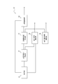
- FIG. 1 It is a figure which shows the structural example of the water treatment system which concerns on one Embodiment of this invention. It is a block diagram which shows the structural example of the control part shown in FIG. It is a flowchart which shows an example of the operation of the water treatment system shown in FIG.
- FIG. 1 is a diagram showing a configuration example of a water treatment system 1 according to an embodiment of the present invention.
- the water treatment system 1 according to the present embodiment is a system that aerates the water to be treated.
- the water to be treated is, for example, wastewater such as domestic wastewater, factory wastewater, rainwater, human waste, desorption liquid after the sludge dehydration process of a sewage treatment plant, and leachate in a landfill, but is not limited to these.
- wastewater such as domestic wastewater, factory wastewater, rainwater, human waste, desorption liquid after the sludge dehydration process of a sewage treatment plant, and leachate in a landfill, but is not limited to these.
- Various types of water that are subject to aeration treatment are subject to aeration treatment.
- the water treatment system 1 shown in FIG. 1 includes reaction tanks 10A, 10B, 10C, a blower unit 20, a blower pipe 30, and a control device 40.
- the water treatment system 1 controls the amount of air supplied from the blower unit 20 to the reaction tanks 10A, 10B, 10C and the supply of water to be treated to the reaction tanks 10A, 10B, 10C by the control device 40, and the reaction tank 1 is used.
- Biological treatment of the water to be treated in 10A, 10B and 10C is performed.
- reaction tanks 10A, 10B, and 10C are not distinguished, they are referred to as reaction tanks 10.
- the reaction tank 10 has an air diffuser 12 inside and is a tank in which activated sludge is stored. Water to be treated flows into (supplies) the reaction tank 10 via a water pump 13. The air diffuser 12 aerates the activated sludge stored in the reaction tank 10 with the air supplied from the blower unit 20. The reaction tank 10 biologically treats the water to be treated in the reaction tank 10 with the aerated activated sludge, and discharges the treated water after the biological treatment.
- Water to be treated is supplied in parallel to each of the reaction tanks 10A, 10B, and 10C.
- the water treatment system 1 will be described with reference to an example including three reaction tanks 10A, 10B, and 10C, but the present invention is not limited thereto.
- the water treatment system 1 includes a plurality of reaction tanks 10. Therefore, the water treatment system 1 may include two or four or more reaction tanks 10.
- the blower unit 20 includes blowers 22A, 22B, 22C, 22D.
- the blowers 22A, 22B, 22C, and 22D are blowers having the same functions as each other.
- the blower unit 20 supplies air for biological treatment to the plurality of reaction tanks 10A, 10B, and 10C via the blower pipe 30.
- blowers 22A, 22B, 22C, and 22D are not distinguished, they are referred to as blowers 22.
- the blower 22 is a blower that introduces air from the outside and discharges the introduced air by a rotating blade portion.
- the blower 22 is, for example, an inlet vane type blower, an inverter type blower, a gear type blower, and the like, but is not limited thereto.
- the side that discharges air from the blade portion is connected to the blower pipe 30 in parallel with each other, and the air is discharged to the blower pipe 30.
- the blower unit 20 will be described with reference to an example including four blowers 22A, 22B, 22C, and 22D, but the present invention is not limited thereto.
- the number of blowers 22 included in the blower unit 20 is arbitrary. Therefore, the sending unit 20 may include one or more blowers 22.
- the blower pipe 30 is a pipe that conducts air inside.
- the blower pipe 30 is connected to the reaction tanks 10A, 10B, 10C.
- the blower pipe 30 includes an introduction pipe 31, a mother pipe 32, and branch pipes 34A, 34B, 34C.
- the introduction pipe 31 is a pipe in which one end is branched and connected to the blowers 22A, 22B, 22C, 22D, and air is supplied from each blower 22.
- the introduction pipe 31 is a pipe whose other end is connected to the mother pipe 32, and the air supplied from each blower 22 is merged and introduced into the mother pipe 32.
- One end of the mother pipe 32 is connected to the introduction pipe 31, and the other end is connected to the branch pipes 34A, 34B, 34C.
- the branch pipe 34A is a pipe in which one end is connected to the mother pipe 32 and the other end is connected to the air diffuser 12 of the reaction tank 10A.
- the branch pipe 34A supplies a part of the air supplied from the mother pipe 32 to the reaction tank 10A.
- the branch pipe 34B is a pipe in which one end is connected to the mother pipe 32 and the other end is connected to the air diffuser 12 of the reaction tank 10B.
- the branch pipe 34B supplies a part of the air supplied from the mother pipe 32 to the reaction tank 10B.
- the branch pipe 34C is a pipe in which one end is connected to the mother pipe 32 and the other end is connected to the air diffuser 12 of the reaction tank 10C.
- the branch pipe 34C supplies a part of the air supplied from the mother pipe 32 to the reaction tank 10C.
- branch pipes 34A, 34B, and 34C are not distinguished, they are referred to as branch pipes 34.
- the branch pipe 34 is provided with an introduction valve 36.
- the introduction valve 36 is a valve that is opened and closed by the control device 40.
- the introduction valve 36 adjusts the amount of air supplied from the branch pipe 34 to the reaction tank 10 by adjusting the opening degree.
- the control device 40 is a device that controls the amount of air supplied to each reaction tank 10. Further, the control device 40 is a device that controls the supply of water to be treated to each reaction tank 10 via the water supply pump 13.
- the control device 40 includes a nitric acid meter 41, an ammonia meter 42, an intake air measuring unit 43, a mother pipe internal pressure measuring unit 44, a branch air volume measuring unit 45, and a control unit 50.
- ammoniacal nitrogen in the water to be treated is nitrified into nitrite nitrogen and nitrate nitrogen by nitrifying bacteria, which are aerobic microorganisms in activated sludge under aerobic conditions.
- nitrifying bacteria which are aerobic microorganisms in activated sludge under aerobic conditions.
- a denitrification reaction by denitrifying bacteria occurs in the region where the amount of oxygen in the water to be treated is small in the reaction tank 10. If a sufficient carbon source is supplied for the denitrification reaction, the denitrification reaction can proceed sufficiently.
- nitrous oxide gas generated due to insufficient nitrification is decomposed, or nitrite is reduced without generating nitrous oxide to obtain nitrogen. It decomposes into carbon dioxide and can remove nitrogen.
- the nitric acid meter 41 is a sensor provided in each reaction tank 10 and detects the progress of the denitrification reaction, that is, the degree of decomposition of nitric acid by measuring the nitric acid concentration of the water to be treated in the reaction tank 10. ..
- the nitric acid in the water to be treated is nitric acid (HNO 3 ), nitrite (HNO 2 ), nitric acid nitrogen (NO 3- N), nitrite nitrogen (NO 2- N), nitric acid nitrogen and nitrite nitrogen. It is a concept including a set of and NO x.
- the ammonia meter 42 is a sensor provided in each reaction tank 10 and detects the progress of the nitrification reaction, that is, the degree of decomposition of ammonia by measuring the ammonia concentration of the water to be treated in the reaction tank 10.
- Ammonia in water to be treated is a concept containing ammonia and ammoniacal nitrogen.
- the intake air measuring unit 43 is provided on the intake side of the blower 22, and is an air volume meter that measures the amount of air taken in by the blower 22.
- the mother pipe internal pressure measuring unit 44 is a pressure gauge attached to the mother pipe 32 and measuring the internal pressure of the mother pipe 32, that is, the pressure of air from the blower unit 20.
- the branch pipe air volume measuring unit 45 is provided in the branch pipe 34. Specifically, the branch pipe air volume measuring unit 45 is provided between the introduction valve 36 and the mother pipe 32 in the branch pipe 34.
- the branch pipe air volume measuring unit 45 is an air volume meter that measures the amount of air supplied from the branch pipe 34 to the reaction tank 10.
- a pressure gauge may be provided in the branch pipe 34 instead of the mother pipe internal pressure measuring unit 44.
- the control unit 50 controls the amount of air supplied to each reaction tank 10 based on the measurement results of each unit described above. Further, the control unit 50 controls the supply of water to be treated to the plurality of reaction tanks 10 according to the calculation result of the pressure loss of the blower series of each of the plurality of reaction tanks 10.
- FIG. 2 is a block diagram showing a configuration example of the control unit 50.
- the control unit 50 shown in FIG. 2 includes an acquisition unit 51, a required air amount calculation unit 52, a target pipe internal pressure calculation unit 53, a blower control unit 54, an introduction air control unit 55, and a water supply control unit 56 to be treated. And.
- the target pipe internal pressure calculation unit 53 is an example of a pressure loss calculation unit.
- the control unit 50 can be realized by, for example, a computer having a CPU (Central Processing Unit) and a memory (for example, a personal computer). When the control unit 50 is realized by a computer, each of the above-described units included in the control unit 50 is realized by storing the program according to the present embodiment in a memory and reading and executing the stored program by the CPU.
- the acquisition unit 51 acquires the measurement results of the nitric acid meter 41, the ammonia meter 42, the intake air measurement unit 43, the mother pipe internal pressure measurement unit 44, and the branch pipe air volume measurement unit 45.
- the acquisition unit 51 outputs the measurement results of the nitric acid meter 41, the ammonia meter 42, and the branch air volume measuring unit 45 to the required air amount calculating unit 52. Further, the acquisition unit 51 outputs the measurement results of the intake air measurement unit 43 and the mother pipe internal pressure measurement unit 44 to the ventilation control unit 54. Further, the acquisition unit 51 outputs the measurement result of the branch air volume measuring unit 45 to the introduction air control unit 55.
- the required air amount calculation unit 52 has been output from the acquisition unit 51 to the state of the water to be treated in the reaction tank 10 (nitrate concentration and ammonia concentration of the water to be treated) and the measurement results of the branch air volume measurement unit 45 from the past to the present. Based on the accumulated data up to, the amount of air (required air amount) required to set the water quality of the water to be treated in the reaction tank 10 to a predetermined target water quality is calculated for each reaction tank 10.
- the required air amount calculation unit 52 stores, for example, a predetermined water quality air amount relationship, and calculates the required air amount based on this water quality air amount relationship.
- the water quality air amount relationship is a relationship between the amount of air supplied to the reaction tank 10 and the amount of change in water quality in the reaction tank 10 when that amount of air is supplied.
- the required air amount calculation unit 52 sets the target concentration of the nitrate concentration of the water to be treated measured by the nitrate meter 41 and the ammonia concentration of the water to be treated measured by the ammonia meter 42 from the water quality air amount relationship obtained in advance. Such an amount of air is calculated as the required amount of air.
- the present invention is not limited to this. In short, any method can be used as long as the amount of air required to bring the water to be treated to a predetermined target water quality can be calculated.
- the required air amount calculation unit 52 outputs the calculation result of the required air amount for each reaction tank 10 to the target pipe internal pressure calculation unit 53 and the introduction air control unit 55.
- the target pipe internal pressure calculation unit 53 calculates a target value (target pipe internal pressure) of the air pressure in the blower pipe 30 based on the required air amount for each reaction tank 10 calculated by the required air amount calculation unit 52.
- the target tube internal pressure is a pressure set as a target pressure of the mother tube internal pressure measuring unit 44 required to supply the required amount of air to each reaction tank 10.
- the target pipe internal pressure calculation unit 53 is a pipe that is the pressure of the air lost due to the pressure loss in the blower pipe 30 when the target air amount of air calculated by the required air amount calculation unit 52 is supplied to the reaction tank 10. to calculate the pressure loss H P.
- the pipe pressure loss H of the pipe is generally calculated based on the following equations (1) and (2).
- H 4 ⁇ f 1 ⁇ ( l / d) ⁇ ( ⁇ ⁇ v 2/2) ⁇ formula (1)
- H f 2 ⁇ ( ⁇ ⁇ v 2/2) ⁇ (2)
- Equation (1) is an equation for calculating the pipe pressure loss H when the pipe is a straight pipe.
- Equation (2) is an equation for calculating the pipe pressure loss H when the pipe is a deformed pipe other than a straight pipe.
- f 1 and f 2 are loss coefficients and are predetermined constants.
- l is the pipe length (m) of the straight pipe.
- d is the inner diameter (m) of the straight pipe.
- the pipe length l and the pipe d are constants determined by the shape of the pipe.
- ⁇ is an air density (kg / m 3 ) and is a predetermined constant.
- v is the flow velocity of air (m / s). In equations (1) and (2), the variable is the flow velocity v.
- the pipe pressure loss H of the pipe changes according to the flow velocity v.
- the flow velocity v is proportional to the air flow rate Q as shown in the following equation (3).
- A is the flow path area, which is a constant determined by the shape of the pipe.
- Q A ⁇ v ⁇ ⁇ ⁇ (3)
- the pipe pressure loss H can be calculated based on the air flow rate Q, that is, the required amount of air.
- the target pipe internal pressure calculation unit 53 calculates the flow velocity v of the air when the required amount of air is passed through the mother pipe 32 and the branch pipe 34 based on the equation (3).
- the target pipe pressure calculation unit 53 calculates a pipe pressure loss H PA in the pathway leading to the reaction vessel 10A from the blower unit 20, a pipe pressure loss H PB in the pathway leading to the reaction vessel 10B from the blower unit 20, the blower unit 20 calculates a pipe pressure loss H PC in the pathway leading to the reaction vessel to 10C.
- the target pipe internal pressure calculation unit 53 calculates the pressure loss HL of the blower series of each of the plurality of reaction tanks 10 based on the following equation (4).
- H L h + H P + H M + H A ⁇ formula (4)
- h is the head pressure of the water to be treated in the reaction vessel 10.
- H M is the mother pipe pressure measuring unit 44, the loss pressure by the branch pipe air amount measuring unit 45 and the introduction valve 36 (loss ventilation pressure).
- HA is the pressure loss due to the air diffuser 12 (pressure loss of the air diffuser).
- the head pressure h is obtained in advance from, for example, the volume of the reaction tank 10.
- the head pressure h may be obtained from the measurement result of a sensor provided in the reaction tank 10 for measuring the water level or the amount of water. In the present embodiment, the same amount of treated water as the amount of water to be treated flowing into the reaction tank 10 flows out from the reaction tank 10. Therefore, the head pressure h is constant.
- Ventilation pressure loss H M is a design value or previously measured values.
- the pressure loss HA of the air diffuser is a pressure determined according to the pollutant load of the water to be treated in the reaction tank 10, and is proportional to the fixed pressure or the square of the supplied air volume depending on the device type of the air diffuser 12.
- the pollution load is the amount of water to be treated supplied to the reaction tank 10 and the concentration of the water to be treated (BOD (Biochemical Oxygen Demand), COD (Chemical Oxygen Demand), NH4, etc.). It is expressed as the product of the substance concentration).
- the target pipe internal pressure calculation unit 53 calculates the pressure loss HL of the ventilation series of each of the plurality of reaction tanks 10. That is, the target pipe pressure calculation part 53, a head pressure h the reaction vessel 10A, a pipe pressure loss H PA, and ventilation pressure loss H MA path leading to the reaction vessel 10A from the blower unit 20, an air diffuser of the reaction vessel 10A 12 the sum of the diffuser pressure loss H AA by is calculated as the pressure loss H LA blower series of reaction vessel 10A. Similarly, the target pipe pressure calculation unit 53 calculates the pressure loss H LC blower series of pressure loss H LB and the reaction vessel 10C blower series of reactor 10B.
- the above-mentioned method for calculating the pressure loss HL is merely an example, and any method capable of calculating the pressure loss HL of the ventilation series of each of the plurality of reaction tanks 10 may be used.
- the target pipe internal pressure calculation unit 53 determines the maximum value of the pressure loss HL (pressure loss H LA , H LB , HLC ) of the ventilation series of each of the plurality of reaction tanks 10 as the target pipe internal pressure.
- the target pipe internal pressure calculation unit 53 outputs the calculation result of the target pipe internal pressure to the ventilation control unit 54. Further, the target pipe internal pressure calculation unit 53 outputs the calculation result of the pressure loss HL for each of the blower series of each of the plurality of reaction tanks 10 to the water supply control unit 56 to be treated.
- the blower control unit 54 controls the supply of air from the blower unit 20 so that the measurement pressure of the mother pipe internal pressure measuring unit 44 becomes the target pipe internal pressure calculated by the target pipe internal pressure calculation unit 53. Specifically, the blower control unit 54 sets the blower unit 20 based on the measurement result of the intake air measurement unit 43 so that the internal pressure in the mother pipe 32 measured by the mother pipe internal pressure measuring unit 44 matches the target pipe internal pressure. Control the amount of air supplied from.
- the introduction air control unit 55 has an introduction valve 36 so that the amount of air supplied to the reaction tank 10 measured by the branch pipe air volume measurement unit 45 matches the required air amount calculated by the required air amount calculation unit 52. Controls the opening degree of. Specifically, the introduction air control unit 55 sets the target air amount as the target value, and the amount of air supplied to the reaction tank 10 is determined by PID (Proportional Integral Differential) control using the measurement result of the branch air volume measurement unit 45. The opening degree of the introduction valve 36 is controlled so as to follow the target air amount.
- PID Proportional Integral Differential
- the water supply control unit 56 to be treated reaches the plurality of reaction tanks 10 via the water supply pump 13 according to the pressure loss HL of the blower series of each of the plurality of reaction tanks 10 calculated by the target pipe internal pressure calculation unit 53. Control the supply of water to be treated.
- FIG. 3 is a flowchart showing an example of the operation of the water treatment system 1 according to the present embodiment, and is a diagram for explaining a water treatment method in the water treatment system 1.
- the operation related to the control of the supply of the water to be treated to each reaction tank 10 will be mainly described.
- the target pipe internal pressure calculation unit 53 calculates the pressure loss HL of the ventilation series of each of the plurality of reaction tanks 10 (step S11). As described above, the target pipe pressure calculation part 53, a head pressure h the reaction vessel 10, a pipe pressure loss H P in the blower tube 30, and the ventilation pressure loss H M, the sum of the diffuser pressure loss H A, blast Calculated as the series pressure loss HL.
- treatment water supply control unit 56 includes a pressure loss H L (maximum pressure loss)
- the pressure loss H L is the maximum blower series
- the pressure loss pressure loss H L is at the minimum blower series H L (minimum pressure It is determined whether or not the difference from the loss) is equal to or greater than a predetermined threshold (step S12).
- the threshold value may be, for example, a numerical value (for example, 0.5 kPa) set by the administrator of the water treatment system 1.
- the threshold value may be, for example, the ratio of the difference between the maximum pressure loss and the minimum pressure loss (for example, 5%) to the maximum pressure loss set by the administrator of the water treatment system 1.
- step S12 When it is determined that the difference between the maximum pressure loss and the minimum pressure loss is not equal to or greater than a predetermined threshold value (step S12: No), the water supply control unit 56 to be treated ends the process.
- the water supply control unit 56 to be treated is the pressure of the blower series of each of the plurality of reaction tanks 10.
- the supply of water to be treated to the plurality of reaction tanks 10 is controlled according to the loss HL (step S13).
- the water to be treated water supply control unit 56 controls the supply of the water to be treated to the plurality of reaction tanks 10 according to the pressure loss HL of the ventilation series of each of the plurality of reaction tanks 10, the water treatment system to that effect.
- the administrator of 1 may be notified.
- the water treatment method includes a calculation step for calculating the pressure loss HL of the blast series of each of the plurality of reaction tanks 10 and a pressure loss HL of the blast series of each of the plurality of reaction tanks 10. Accordingly, it includes a control step of controlling the supply of water to be treated to the plurality of reaction tanks 10.
- the pressure loss HL of the ventilation series of each of the plurality of reaction tanks 10 may be calculated outside the water treatment system 1.
- the water treatment system 1 performs the treatment described with reference to FIG. 3 at a predetermined frequency (for example, once a day).
- the water treatment system 1 may perform the treatment described with reference to FIG. 3 in real time.
- the water to be treated water supply control unit 56 performs biological treatment on the water to be treated supplied to the reaction tank 10 and flows out from the reaction tank 10 as treated water.
- the supply of water to be treated to the reaction vessel 10 is controlled at a speed corresponding to the time until.
- the water treatment system including the reaction tanks 10 (reaction tanks 10A, 10B, 10C) shown in FIG. 1, the blower unit 20 and the blower pipe 30 is provided with the first method and the second method described in the background art.
- the operation when the method of is applied will be described.
- the amount of water to be treated in the reaction tanks 10A, 10B and 10C is constant and the head pressure h is 60 kPa.
- the same amount of water to be treated is supplied to each reaction tank 10, and for example, each reaction tank 10 is supplied with water to be treated in an amount of 2000 m 3 / hr. And.
- the maximum assumed pressure loss HL is calculated, and air is supplied to the plurality of reaction tanks 10 with a blowing pressure corresponding to the calculated pressure loss HL.
- the pipe pressure loss H P in the path of the air tube 30 leading to the reaction vessel 10A from blower unit 20 is assumed to be 5kPa at maximum.
- air diffuser pressure loss H A by an air diffuser 12 is assumed to be 3kPa at maximum.
- the head pressure h (60 kPa), the sum of the largest pipe pressure loss H P envisioned (5 kPa), the maximum air diffuser pressure loss H A contemplated (3 kPa), i.e., 68 kPa air blowing unit 20 It is set as the ventilation pressure by.
- the air is blown to the air system of each reaction tank 10 with an excessive pressure. Therefore, the blast power of the blast unit 20 is wasted, and the efficiency of power utilization in water treatment cannot be sufficiently improved.
- the pressure loss of each blast system is calculated based on the water quality of the water to be treated in each reaction tank 10, and a plurality of blast pressures corresponding to the calculated maximum pressure loss HL are used.
- Air is supplied to the reaction vessel 10 of the above.
- the pressure loss H L of the air line of the reaction vessel 10A is 4 kPa
- the pressure loss H L of the air line of the reaction vessel 10B is 3 kPa
- the pressure loss H L of the air line of the reactor 10C is a 2kPa
- the pressure loss HA of the air diffuser is 2 kPa.
- the blowing pressure of the blowing unit 20 is set based on the actual pressure loss HL of the blowing series of each reaction tank 10 and the actual pressure loss HA of the air diffuser. In comparison, the blowing pressure of the blowing unit 20 can be reduced, that is, the blowing power of the blowing unit 20 can be reduced.
- the air is blown to the reaction tanks 10B and 10C other than the reaction tank 10 having the maximum pressure loss HL of the blower series with an excessive pressure. Therefore, the blast power of the blast unit 20 is wasted, and the efficiency of power utilization in water treatment may not be sufficiently improved.
- the blower unit 20 is controlled by controlling the supply of the water to be treated to each of the plurality of reaction tanks 10 according to the pressure loss HL of the blower series of each of the plurality of reaction tanks 10.
- the pressure loss HL of the blower series of each of the plurality of reaction tanks 10 in the present embodiment will be described.
- the water supply control unit 56 to be treated has a pollution load ratio or an amount of pollution load of the water to be treated to be supplied to the plurality of reaction tanks 10 so as to reduce the difference in the pressure loss HL of the ventilation series of each of the plurality of reaction tanks 10.
- the pollution load ratio is the ratio of the pollution load of the water to be treated in each reaction tank 10 to the pollution load of the water to be treated in all the reaction tanks 10.
- the water to be treated control unit 56 assumes that the total amount of water to be treated to be supplied to the plurality of reaction tanks 10 is constant, and supplies each reaction tank 10 Control the amount of water to be treated.
- the pollution load is represented by the product of the amount of water to be treated supplied to the reaction tank 10 and the concentration of the water to be treated supplied to the reaction tank 10.
- the pollution load ratio of the water to be treated supplied to each reaction tank 10 is a value proportional to the amount of the water to be treated to be supplied.
- the pressure loss H LA blower series of reactors 10A is 4 kPa
- the pressure loss H LB blower series of reaction vessel 10B is 3 kPa
- the pressure loss H LC blower series of reactor 10C is a 2kPa To do.
- the pressure loss HA of the air diffuser for each of the reaction tanks 10A, 10B, and 10C is 2 kPa.
- the water supply control unit 56 to be treated reduces the amount of water to be treated to the reaction tank 10A having the largest pressure loss HL while keeping the total amount of water to be treated to be supplied to the reaction tanks 10A, 10B and 10C constant. , Increase the amount of water to be treated supplied to the reaction vessel 10C having the smallest pressure loss HL.
- the water to be treated water supply control unit 56 sets the amount of water to be treated to be supplied to the reaction tank 10A to 1500 m 3 / hr, and the amount of water to be treated to be supplied to the reaction tank 10C to be 2500 m 3 / hr. Further, the water to be treated water supply control unit 56 keeps the amount of water to be treated to be supplied to the reaction tank 10B at 2000 m 3 / hr.
- the reaction vessel is water treated water to be supplied is reduced that the 10A, air diffuser pressure loss H AA by an air diffuser 12 of the reaction vessel 10A, for example, be reduced to 1.8 kPa. Further, by reducing the amount of water to be treated supplied to the reaction tank 10A, the amount of air required in the reaction tank 10A is reduced. Required amount of air in the reaction vessel 10A and the air diffuser pressure loss H AA that is reduced, the pipe pressure loss H PA in blown series of reactors 10A also reduced compared with the previous control of the supply amount of the water to be treated.
- the air diffuser pressure loss H AC by an air diffuser 12 of the reaction vessel 10C increases the 2.2KPa.
- the required amount of air in the reaction tank 10C increases.
- Required amount of air in the reaction vessel 10C and the air diffuser pressure loss H that AC is increased, also the pipe pressure loss H PC in blast sequence of reaction vessel 10C increases compared with the previous control of the supply amount of the water to be treated. For example, as described above, although the piping pressure loss H PC before controlling the supply amount of the water to be treated was 2 kPa, and after control of the supply amount of the water to be treated, pipe pressure loss H PC is increased to 2.8kPa ..
- the same amount of water to be treated can be treated with a smaller blowing pressure as compared with the first method and the second method. Therefore, it is possible to reduce the waste of the blown electric power of the blower unit 20 and improve the efficiency of electric power utilization in the water treatment.
- the water supply control unit 56 to be treated increases the amount of pollutant load of the water to be treated to be supplied to the reaction tank 10 as the reaction tank 10 having a smaller pressure loss HL of the blower series has a smaller pressure loss HL. Assuming that the concentration of the water to be treated is constant, the water supply control unit 56 supplies the water to be treated to the reaction tank 10B and the reaction tank 10C without changing the amount of the water to be treated to the reaction tank 10A. Increase the amount. Further, the water to be treated water supply control unit 56 increases the amount of water to be treated to be supplied to the reaction tank 10C to be larger than the amount of increase of the water to be treated to be supplied to the reaction tank 10B.
- treatment water supply control unit 56 for example, the supply amount of the water to be treated into the reaction vessel 10A is still in 2000m 3 / hr, 2500m 3 a supply amount of the water to be treated to the reaction tank 10B It is set to / hr, and the amount of water to be treated to the reaction tank 10C is set to 3000 m 3 / hr.
- the reaction vessel 10B, at 10C, by supplying the amount of water to be treated increases, increased air diffuser pressure loss H A and the pipe pressure drop H P is the pressure loss H L increases.
- the increase in pressure loss H LC blower series of reactor 10C the pressure of the air line of the reactor 10B It is more than the amount of increase in loss HLB. Therefore, the reaction vessel 10B, 10C pressure loss H LB of the blower series, H LC approaches the pressure loss H LA blower series of reaction vessel 10A, the pressure loss of the air line of the reaction vessel 10 are equalized, Air is blown to each reaction vessel 10 with an appropriate pressure loss without excess or deficiency. Therefore, it is possible to reduce the waste of the blown electric power of the blower unit 20 and improve the efficiency of electric power utilization in the water treatment.
- the water supply control unit 56 uses an example in which the amount of the pollutant load of the water to be treated to be supplied to the reaction tank 10 is increased as the reaction tank 10 having a smaller pressure loss HL in the blower series is used. I explained, but it is not limited to this.
- the water supply control unit 56 may reduce the amount of pollutant load of the water to be treated to be supplied to the reaction tank 10 as the reaction tank 10 having a larger pressure loss HL of the blower series has a larger pressure loss HL. By doing so, the pressure loss of the blower series of each reaction tank 10 is equalized, so that the waste of the blower power of the blower unit 20 can be reduced and the efficiency of power utilization in water treatment can be improved.
- the concentration of the water to be treated supplied to each reaction tank 10 has been described by using an example in which the concentration is constant, but the present invention is not limited to this.
- the pollution load is represented by the product of the amount of water to be treated supplied to the reaction tank 10 and the concentration of the water to be treated supplied to the reaction tank 10. Therefore, the water to be treated water supply control unit 56 controls the amount of the pollution load or the pollution load ratio of the water to be treated to be supplied to each reaction tank 10 by controlling the concentration of the water to be treated to be supplied to the reaction tank 10. You may.
- the water to be treated control unit 56 controls the supply of the water to be treated to the plurality of reaction tanks 10, for example, the water to be treated to the plurality of reaction tanks 10 at an arbitrary pollution load ratio or the amount of the pollution load.
- the water supply control unit 56 to be treated adopts the pollution load ratio or the amount of the pollution load.
- the water supply control unit 56 to be treated has a pollution load ratio or a pollution load based on the degree of deviation from the predetermined range.
- the pressure loss HL of the blower series of the plurality of reaction tanks 10 is compared again by changing the amount of.
- the water supply control unit 56 to be treated determines the pollutant load ratio or the amount of pollutant load in which the difference in pressure loss HL of the blower series of the plurality of reaction tanks 10 falls within a predetermined range.
- the water treatment system 1 has a plurality of reaction tanks 10, a blower pipe 30 which is a pipe connected to the plurality of reaction tanks 10, and a plurality of reaction tanks via the blower pipe 30.
- the blower unit 20 that supplies air to 10 and the target pipe pressure calculation unit 53 as the pressure loss calculation unit that calculates the pressure loss HL of the blower series of each of the plurality of reaction tanks, and the calculated plurality of reaction tanks 10 respectively.
- the water to be treated water supply control unit 56 for controlling the supply of the water to be treated to the plurality of reaction tanks 10 according to the pressure loss HL of the blower series of the above is provided.
Landscapes
- Life Sciences & Earth Sciences (AREA)
- Biodiversity & Conservation Biology (AREA)
- Microbiology (AREA)
- Hydrology & Water Resources (AREA)
- Engineering & Computer Science (AREA)
- Environmental & Geological Engineering (AREA)
- Water Supply & Treatment (AREA)
- Chemical & Material Sciences (AREA)
- Organic Chemistry (AREA)
- Health & Medical Sciences (AREA)
- Molecular Biology (AREA)
- Activated Sludge Processes (AREA)
Priority Applications (3)
| Application Number | Priority Date | Filing Date | Title |
|---|---|---|---|
| EP20874824.4A EP4043407A4 (en) | 2019-10-07 | 2020-09-10 | WATER TREATMENT SYSTEM, WATER TREATMENT PROCESS AND PROGRAM |
| JP2021550537A JP7572366B2 (ja) | 2019-10-07 | 2020-09-10 | 水処理システム、水処理方法およびプログラム |
| US17/658,121 US12378143B2 (en) | 2019-10-07 | 2022-04-06 | Water treatment system, water treatment method, and recording medium |
Applications Claiming Priority (2)
| Application Number | Priority Date | Filing Date | Title |
|---|---|---|---|
| JP2019-184810 | 2019-10-07 | ||
| JP2019184810 | 2019-10-07 |
Related Child Applications (1)
| Application Number | Title | Priority Date | Filing Date |
|---|---|---|---|
| US17/658,121 Continuation-In-Part US12378143B2 (en) | 2019-10-07 | 2022-04-06 | Water treatment system, water treatment method, and recording medium |
Publications (1)
| Publication Number | Publication Date |
|---|---|
| WO2021070552A1 true WO2021070552A1 (ja) | 2021-04-15 |
Family
ID=75437869
Family Applications (1)
| Application Number | Title | Priority Date | Filing Date |
|---|---|---|---|
| PCT/JP2020/034373 Ceased WO2021070552A1 (ja) | 2019-10-07 | 2020-09-10 | 水処理システム、水処理方法およびプログラム |
Country Status (4)
| Country | Link |
|---|---|
| US (1) | US12378143B2 (https=) |
| EP (1) | EP4043407A4 (https=) |
| JP (1) | JP7572366B2 (https=) |
| WO (1) | WO2021070552A1 (https=) |
Citations (5)
| Publication number | Priority date | Publication date | Assignee | Title |
|---|---|---|---|---|
| JPS5799385A (en) * | 1980-12-15 | 1982-06-21 | Toshiba Corp | Treating device for water |
| JP2004223499A (ja) * | 2003-01-24 | 2004-08-12 | Takeshi Yamamoto | エアレーション装置及びこのエアレーション装置を備えた水処理システム |
| JP2005199115A (ja) * | 2004-01-13 | 2005-07-28 | Toshiba Corp | 下水処理場の曝気風量制御装置 |
| JP2017127813A (ja) * | 2016-01-20 | 2017-07-27 | 株式会社日立製作所 | 水処理システム |
| JP2018202371A (ja) * | 2017-06-09 | 2018-12-27 | 株式会社クボタ | 排水分配装置及び有機性排水処理システム |
Family Cites Families (2)
| Publication number | Priority date | Publication date | Assignee | Title |
|---|---|---|---|---|
| JP2018167249A (ja) | 2017-03-30 | 2018-11-01 | メタウォーター株式会社 | 廃水処理システム、空気供給量制御装置及び空気供給量制御方法 |
| JP7087429B2 (ja) * | 2018-02-13 | 2022-06-21 | 三浦工業株式会社 | 水処理装置 |
-
2020
- 2020-09-10 WO PCT/JP2020/034373 patent/WO2021070552A1/ja not_active Ceased
- 2020-09-10 JP JP2021550537A patent/JP7572366B2/ja active Active
- 2020-09-10 EP EP20874824.4A patent/EP4043407A4/en active Pending
-
2022
- 2022-04-06 US US17/658,121 patent/US12378143B2/en active Active
Patent Citations (5)
| Publication number | Priority date | Publication date | Assignee | Title |
|---|---|---|---|---|
| JPS5799385A (en) * | 1980-12-15 | 1982-06-21 | Toshiba Corp | Treating device for water |
| JP2004223499A (ja) * | 2003-01-24 | 2004-08-12 | Takeshi Yamamoto | エアレーション装置及びこのエアレーション装置を備えた水処理システム |
| JP2005199115A (ja) * | 2004-01-13 | 2005-07-28 | Toshiba Corp | 下水処理場の曝気風量制御装置 |
| JP2017127813A (ja) * | 2016-01-20 | 2017-07-27 | 株式会社日立製作所 | 水処理システム |
| JP2018202371A (ja) * | 2017-06-09 | 2018-12-27 | 株式会社クボタ | 排水分配装置及び有機性排水処理システム |
Non-Patent Citations (1)
| Title |
|---|
| See also references of EP4043407A4 * |
Also Published As
| Publication number | Publication date |
|---|---|
| US20220227647A1 (en) | 2022-07-21 |
| EP4043407A1 (en) | 2022-08-17 |
| JPWO2021070552A1 (https=) | 2021-04-15 |
| EP4043407A4 (en) | 2023-11-01 |
| US12378143B2 (en) | 2025-08-05 |
| JP7572366B2 (ja) | 2024-10-23 |
Similar Documents
| Publication | Publication Date | Title |
|---|---|---|
| CN103443038B (zh) | 水处理系统及其曝气风量控制方法 | |
| CN103261103B (zh) | 包括亚硝酸盐浓度在线测量的序列生物反应器内处理水的方法 | |
| CN101913699B (zh) | 在废水处理生物反应器区室中提供需氧介质的方法及相关系统 | |
| US9902635B2 (en) | Method for deammonification process control using pH, specific conductivity, or ammonia | |
| JP7586949B2 (ja) | 水処理システム、制御装置及び制御方法 | |
| CN102725235A (zh) | 用于处理连续生物反应器内的水的方法,其包括在线测量所述反应器内亚硝酸盐浓度 | |
| JP5685504B2 (ja) | 水処理システムおよびその曝気風量制御方法 | |
| KR20150096407A (ko) | 향상된 제어 알고리즘을 이용한 최적화 방법 및 폭기 성능 | |
| CN115259413A (zh) | 一种用于精准曝气系统的风量控制方法 | |
| CN106573807B (zh) | 曝气风量计算装置以及水处理系统 | |
| JPH09248596A (ja) | 下水処理場の水質制御装置 | |
| CN113354069B (zh) | 一种mbr工艺精确曝气控制系统及方法 | |
| WO2021070552A1 (ja) | 水処理システム、水処理方法およびプログラム | |
| JP6391325B2 (ja) | N2o抑制型水処理方法及び処理装置 | |
| CN103086509B (zh) | 氮、磷除去处理方法及氮、磷除去处理装置 | |
| JP2015054271A (ja) | 排水の処理装置および排水の処理方法 | |
| JP2024168077A (ja) | 有機物含有水の処理方法及び有機物含有水の処理装置 | |
| JP2000325980A (ja) | 汚水処理方法及び汚水処理装置 | |
| JP6677502B2 (ja) | 廃水処理システム、空気供給量制御装置及び空気供給量制御方法 | |
| US20140231360A1 (en) | NH3 Feed-Forward Control of Blower Output | |
| JP2015054270A (ja) | 排水の処理装置および排水の処理方法 | |
| Puig et al. | On-line oxygen uptake rate as a new tool for monitoring and controlling the SBR process | |
| CN118488929A (zh) | 用于控制废水处理设施中的一氧化二氮产生的系统和方法 | |
| CN119993297A (zh) | 氧化亚氮计算结构、减排系统及方法 | |
| JPS61107999A (ja) | 消化槽の種汚泥返送制御装置 |
Legal Events
| Date | Code | Title | Description |
|---|---|---|---|
| 121 | Ep: the epo has been informed by wipo that ep was designated in this application |
Ref document number: 20874824 Country of ref document: EP Kind code of ref document: A1 |
|
| ENP | Entry into the national phase |
Ref document number: 2021550537 Country of ref document: JP Kind code of ref document: A |
|
| NENP | Non-entry into the national phase |
Ref country code: DE |
|
| ENP | Entry into the national phase |
Ref document number: 2020874824 Country of ref document: EP Effective date: 20220509 |