WO2021066050A1 - バックライトおよび液晶表示装置 - Google Patents
バックライトおよび液晶表示装置 Download PDFInfo
- Publication number
- WO2021066050A1 WO2021066050A1 PCT/JP2020/037261 JP2020037261W WO2021066050A1 WO 2021066050 A1 WO2021066050 A1 WO 2021066050A1 JP 2020037261 W JP2020037261 W JP 2020037261W WO 2021066050 A1 WO2021066050 A1 WO 2021066050A1
- Authority
- WO
- WIPO (PCT)
- Prior art keywords
- blue light
- light source
- cholesteric
- layer
- wavelength
- Prior art date
- Legal status (The legal status is an assumption and is not a legal conclusion. Google has not performed a legal analysis and makes no representation as to the accuracy of the status listed.)
- Ceased
Links
Images


Classifications
-
- F—MECHANICAL ENGINEERING; LIGHTING; HEATING; WEAPONS; BLASTING
- F21—LIGHTING
- F21S—NON-PORTABLE LIGHTING DEVICES; SYSTEMS THEREOF; VEHICLE LIGHTING DEVICES SPECIALLY ADAPTED FOR VEHICLE EXTERIORS
- F21S2/00—Systems of lighting devices, not provided for in main groups F21S4/00 - F21S10/00 or F21S19/00, e.g. of modular construction
-
- F—MECHANICAL ENGINEERING; LIGHTING; HEATING; WEAPONS; BLASTING
- F21—LIGHTING
- F21V—FUNCTIONAL FEATURES OR DETAILS OF LIGHTING DEVICES OR SYSTEMS THEREOF; STRUCTURAL COMBINATIONS OF LIGHTING DEVICES WITH OTHER ARTICLES, NOT OTHERWISE PROVIDED FOR
- F21V9/00—Elements for modifying spectral properties, polarisation or intensity of the light emitted, e.g. filters
- F21V9/30—Elements containing photoluminescent material distinct from or spaced from the light source
- F21V9/32—Elements containing photoluminescent material distinct from or spaced from the light source characterised by the arrangement of the photoluminescent material
-
- F—MECHANICAL ENGINEERING; LIGHTING; HEATING; WEAPONS; BLASTING
- F21—LIGHTING
- F21V—FUNCTIONAL FEATURES OR DETAILS OF LIGHTING DEVICES OR SYSTEMS THEREOF; STRUCTURAL COMBINATIONS OF LIGHTING DEVICES WITH OTHER ARTICLES, NOT OTHERWISE PROVIDED FOR
- F21V9/00—Elements for modifying spectral properties, polarisation or intensity of the light emitted, e.g. filters
- F21V9/40—Elements for modifying spectral properties, polarisation or intensity of the light emitted, e.g. filters with provision for controlling spectral properties, e.g. colour, or intensity
-
- G—PHYSICS
- G02—OPTICS
- G02B—OPTICAL ELEMENTS, SYSTEMS OR APPARATUS
- G02B5/00—Optical elements other than lenses
- G02B5/20—Filters
- G02B5/26—Reflecting filters
Definitions
- the present invention relates to a backlight and a liquid crystal display device using this backlight.
- the direct type backlight has a structure in which a plurality of light sources are spread on the back side of the liquid crystal in the liquid crystal panel, and unlike the edge type backlight, it can be divided into blocks of several light sources. Therefore, according to the direct type method, the backlight in the bright portion of the image can be bright, and the backlight in the dark portion of the image can be darkened. This is a function called partial drive, high dynamic range (HDR), and local dimming, which can increase the contrast of the entire image.
- HDR high dynamic range
- Patent Document 1 unintended reflection occurs due to the side surface of the opening, and the light escaping to the outside of the system cannot be ignored and the light utilization efficiency is inferior. Further, if the opening is provided above a certain level, the screen layer is torn off, so that the aperture ratio is limited and there is room for further improvement.
- the present invention has the following configurations.
- the board Multiple blue light sources discretely arranged on one side of the board, It has a patterned cholesteric layer arranged apart from the blue light source on the light emitting side of the blue light source.
- a backlight characterized in that the integrated reflectance of the portion of the patterned cholesteric layer superimposed on the blue light source at a wavelength of 450 nm is 30% or more higher than the integrated reflectance of the portion of the patterned cholesteric layer not superimposed on the blue light source at a wavelength of 450 nm. ..
- the portion of the patterned cholesteric layer superimposed on the blue light source has a selective reflection center wavelength shorter than a wavelength of 500 nm, and the portion of the patterned cholesteric layer not superimposed on the blue light source is selected with a wavelength longer than 500 nm.
- the backlight according to [1] or [2], wherein the portion of the patterned cholesteric layer superimposed on the blue light source and the portion of the patterned cholesteric layer not superimposed on the blue light source are made of the same material. ..
- the partial cholesteric film has a base material and a plurality of cholesteric reflecting portions arranged apart from the base material, and the cholesteric reflecting portion is provided so as to be superimposed on the blue light source and has a selective reflection center wavelength.
- a backlight characterized by having a emission center wavelength of ⁇ 50 nm of a blue light source.
- Further having a diffuser plate The backlight according to [12] or [13], wherein the partial cholesteric film is located between the blue light source and the diffuser.
- the present invention it is possible to provide a backlight having an excellent balance between light utilization efficiency and uniformity of brightness of irradiation light even if the thickness is reduced.
- FIG. 1 is a cross-sectional view conceptually showing an example of the backlight of the present invention (an example in which the patterned cholesteric layer is located between the substrate and the diffuser).
- FIG. 2 is a cross-sectional view conceptually showing another example of the backlight of the present invention (an example in which the patterned cholesteric layer is located on the side opposite to the substrate with respect to the diffuser plate).
- FIG. 3A is a top view conceptually showing an example of a pattern included in the patterned cholesteric layer of the present invention.
- FIG. 3B is a top view conceptually showing an example of a pattern included in the patterned cholesteric layer of the present invention.
- FIG. 1 is a cross-sectional view conceptually showing an example of the backlight of the present invention (an example in which the patterned cholesteric layer is located between the substrate and the diffuser).
- FIG. 2 is a cross-sectional view conceptually showing another example of the backlight of the present invention (an example in which the
- FIG. 3C is a top view conceptually showing an example of a pattern included in the patterned cholesteric layer of the present invention.
- FIG. 3D is a top view conceptually showing an example of a pattern included in the patterned cholesteric layer of the present invention.
- FIG. 4A is a diagram conceptually showing an example of the layer structure of the backlight of the present invention.
- FIG. 4B is a diagram conceptually showing an example of the layer structure of the backlight of the present invention.
- FIG. 4C is a diagram conceptually showing an example of the layer structure of the backlight of the present invention.
- FIG. 4D is a diagram conceptually showing an example of the layer structure of the backlight of the present invention.
- FIG. 4A is a diagram conceptually showing an example of the layer structure of the backlight of the present invention.
- FIG. 4B is a diagram conceptually showing an example of the layer structure of the backlight of the present invention.
- FIG. 4C is a diagram conceptually showing an example of the layer
- FIG. 4E is a diagram conceptually showing an example of the layer structure of the backlight of the present invention.
- FIG. 4F is a diagram conceptually showing an example of the layer structure of the backlight of the present invention.
- FIG. 5 is a diagram conceptually showing an example of a partial cholesteric film.
- FIG. 6 is a top view of the exposure mask used for forming the patterned cholesteric layer of the embodiment of the present invention.
- FIG. 7 is a top view of the patterned cholesteric layer according to the embodiment of the present invention.
- FIG. 8 is a top view of a patterned cholesteric layer of another example of the embodiment of the present invention.
- FIG. 9A is a cross-sectional view conceptually showing an example of a backlight according to an embodiment of the present invention.
- FIG. 9B is a cross-sectional view conceptually showing an example of a backlight according to an embodiment of the present invention.
- FIG. 9C is a cross-sectional view conceptually showing
- the integrated reflectance of the portion of the patterned cholesteric layer that does not overlap the blue light source is the integrated reflectance of the portion of the patterned cholesteric layer that overlaps the midpoint of two adjacent blue light sources. It was regarded as the integrated reflectance of the part of the cholesteric layer that did not overlap with the blue light source.
- the integrated reflectance of the portion of the patterned cholesteric layer superimposed on the blue light source is the integral reflectance of the patterned cholesteric layer of the portion superimposed on the center of the blue light source, and the blue light source of the patterned cholesteric layer. It was regarded as the integrated reflectance of the part superimposed on.
- "superimposing on a blue light source” means that there is an overlapping positional relationship when visually recognized from a direction perpendicular to the substrate on which the blue light source is arranged.
- the numerical range represented by using “-” means a range including the numerical values before and after "-" as the lower limit value and the upper limit value.
- the integrated reflectance R ( ⁇ ) at the wavelength ⁇ is a large integrating sphere device (manufactured by JASCO Corporation) on a spectrophotometer (manufactured by JASCO Corporation, V-550) so that light is incident from the surface of the cholesteric layer. , ILV-471) may be attached and measured by an optical trap.
- the selective reflection center wavelength of the cholesteric layer may be determined by the following method. That is, when the integrated reflectance is measured by the method described above, a spectral waveform of the integrated reflectance, which is a mountain shape (convex upward) with the wavelength as the horizontal axis, can be obtained. The average reflectance (arithmetic average) of the maximum value and the minimum value of the integrated reflectance at this time is obtained, and the value of the wavelength on the short wavelength side of the two wavelengths at the two intersections of the waveform and the average reflectance is ⁇ (nm). ), The value of the wavelength on the long wavelength side is ⁇ (nm), and it is calculated by the following formula.
- Selective reflection center wavelength ( ⁇ + ⁇ ) / 2
- a method of measuring the selective reflection center wavelength and the full width at half maximum by measuring the transmission spectrum of the sample with Axoscan of Axometrix or the like is exemplified.
- a transmission spectrum waveform having a valley shape (convex downward) with the wavelength on the horizontal axis can be obtained.
- the average reflectance (arithmetic average) of the maximum value and the minimum value of the transmittance at this time is obtained, and the value of the wavelength on the short wavelength side of the two wavelengths of the two intersections of the waveform and the average transmittance is ⁇ (nm).
- the selective reflection center wavelength and the half-value width are calculated by the above equation.
- blue light is light having a wavelength band of 400 to 495 nm.
- FIG. 1 conceptually shows an example of the backlight of the present invention.
- the backlight 10A shown in FIG. 1 is arranged apart from the substrate 11, a plurality of blue light sources 12 arranged separately from each other on one side of the substrate 11, and the blue light source 12 on the blue light emitting side from the blue light source 12. It has a diffuser plate 16 and a patterned cholesteric layer 14 arranged between the substrate 11 (blue light source 12) and the diffuser plate 16.
- the patterned cholesteric layer 14 has a portion 14a superimposed on the blue light source 12 and a portion 14b not superimposed on the blue light source 12.
- the integrated reflectance of the portion 14a superimposed on the blue light source 12 at a wavelength of 450 nm and the integrated reflectance of the portion 14b not superimposed on the blue light source 12 at a wavelength of 450 nm are different. Specifically, the integrated reflectance of the portion 14a superimposed on the blue light source 12 of the patterned cholesteric layer 14 at a wavelength of 450 nm is 30% or more higher than the integrated reflectance of the portion 14b not superimposed on the blue light source 12 at a wavelength of 450 nm. ..
- the patterned cholesteric layer 14 is adhered to the diffusion plate 16 via the pressure-sensitive adhesive layer 15.
- the substrate 11 and the blue light source 12 are covered with a transparent protective layer 13. Further, a wavelength conversion sheet 17, two prism sheets 18, and a reflective polarizer layer 19 are provided above the diffuser plate 16 in the drawing.
- FIG. 2 conceptually shows a different example of the backlight of the present invention.
- the backlight 10B shown in FIG. 2 is arranged apart from the substrate 11, a plurality of blue light sources 12 arranged separately from each other on one side of the substrate 11, and the blue light source 12 on the blue light emitting side from the blue light source 12. It is the same as the backlight 10A shown in FIG. 1 in that it has the diffused plate 16 and the patterned cholesteric layer 14. However, in the backlight 10B shown in FIG. 2, the patterned cholesteric layer 14 is located on the opposite side of the diffuser plate 16 from the substrate 11 (blue light source 12). That is, in this example, the diffuser plate 16 is located between the blue light source 12 and the patterned cholesteric layer 14.
- the patterned cholesteric layer 14 has a portion 14a superimposed on the blue light source 12 and a portion 14b not superimposed on the blue light source 12.
- the integrated reflectance of the portion 14a superimposed on the blue light source 12 at a wavelength of 450 nm and the integrated reflectance of the portion 14b not superimposed on the blue light source 12 at a wavelength of 450 nm are different.
- the integrated reflectance of the portion 14a superimposed on the blue light source 12 of the patterned cholesteric layer 14 at a wavelength of 450 nm is 30% or more higher than the integrated reflectance of the portion 14b not superimposed on the blue light source 12 at a wavelength of 450 nm. ..
- the patterned cholesteric layer 14 is adhered to the diffusion plate 16 via the pressure-sensitive adhesive layer 15. Further, in the example of FIG. 2, the substrate 11 and the blue light source 12 are covered with the transparent protective layer 13. Further, a wavelength conversion sheet 17, two prism sheets 18, and a reflective polarizer layer 19 are provided on the diffuser plate 16.
- the backlight shown in FIGS. 1 and 2 converts the blue light emitted from the blue light source 12 into, for example, green light and red light on the wavelength conversion sheet 17, and converts the blue light emitted from the blue light source 12 into blue light.
- white light white planar illumination
- the brightness uniformity of the emitted light is improved by having the patterned cholesteric layer 14.
- the members constituting the backlight will be described in detail.
- the backlight of the present invention has a substrate.
- the material of the substrate used in the present invention is not particularly limited as long as it can stably hold the blue light source.
- Materials for the substrate include paper phenol substrate, paper epoxy substrate, glass epoxy substrate, composite substrate epoxy substrate, glass composite substrate, glass polyimide substrate, BT (bismaleimide triazine resin) substrate, Teflon (registered trademark) substrate, and metal.
- Examples include a base substrate.
- a flexible substrate made of a resin such as a polyester resin, a polyimide resin, and a liquid crystal polymer can also be used.
- the substrate preferably has as high a light reflectance as possible so that it can reflect the light of a blue light source, and the reflectance is increased by means such as kneading a white pigment into the substrate or containing fine bubbles in the substrate.
- a reflective substrate is preferably used.
- the substrate may have a reflective layer on its surface.
- the backlight of the present invention has a blue light source.
- a plurality of blue light sources used in the present invention are arranged discretely on a substrate.
- the blue light source of the present invention may be any light source that emits blue light, and is not limited to a specific one.
- a light source that emits blue light having a emission center wavelength (peak wavelength) in a wavelength band of about 425 to about 485 nm for example, a blue light emitting diode (blue LED) or a blue laser light source can be used.
- the blue LED is preferable because it is excellent in high brightness and energy saving.
- an inorganic LED, an organic LED, or the like can be used.
- the number of blue light sources to be applied, the location of the blue light source, and the like can be appropriately set according to the required performance such as the size and brightness of the display to which the direct backlight is applied.
- the direct-type backlight of the present invention may include a blue light source as a light source, and may include other light sources such as a white light source, a green light source, and a red light source. Further, the surface of the blue light source may be covered with a transparent protective layer.
- the transparent protective layer protects the blue light source from the external environment and can appropriately maintain the distance between the blue light source and the adjacent layer. Examples of the layer adjacent to the blue light source include a diffuser plate and a patterned cholesteric layer.
- the transparent protective layer may cover only the blue light source, or may cover the entire surface of the substrate or the reflective layer (if any) including the portion without the blue light source.
- the transparent protective layer includes (meth) acrylic resin, polyolefin resin, cycloolefin polymer resin, polycarbonate resin, polyurethane resin, polystyrene resin, polyimide resin, epoxy resin, polyester resin, polyether resin, silicone resin, and (meth). Examples thereof include a layer made of an acrylic monomer / oligomer, a urethane acrylate monomer / oligomer, a resin obtained by polymerizing an epoxy acrylate monomer / oligomer, and the like.
- the backlight of the present invention may have a protective film on a blue light source.
- the protective film physically protects the blue light source and can appropriately maintain the distance between the blue light source and the adjacent layer.
- Examples of the layer adjacent to the blue light source include a diffuser plate and a patterned cholesteric layer.
- the protective film may be present only on the blue light source, or may be present on the substrate including the portion without the blue light source, or on the entire surface on the reflective layer (if present). Further, the protective film may be used together with the above-mentioned transparent protective layer.
- the protective film may be located above or below the transparent protective layer, but from the viewpoint of ease of manufacture, it is preferable that the blue light source, the transparent protective layer, and the protective film are laminated in this order. Further, when the protective film and the transparent protective layer are used in combination, it is also preferable that the refractive indexes of both are different.
- the material of the protective film include polyester resin such as polyethylene terephthalate (PET), polycarbonate, (meth) acrylic resin, polyvinyl chloride, epoxy resin, polyurethane, cycloolefin polymer, polyamide, polyolefin, cellulose resin, and silicone. Examples include resin.
- the (meth) acrylic resin is a general term including an acrylic resin and a methacryloyl resin.
- the protective film a resin film made of polyester resin, (meth) acrylic resin or cellulose resin is preferable.
- the thickness of the protective film is preferably 12 to 300 ⁇ m, more preferably 25 to 200 ⁇ m.
- the protective film is preferably bonded to a blue light source or a functional layer (for example, a transparent protective layer) on the surface thereof via an adhesive or an adhesive.
- the pressure-sensitive adhesive and the adhesive to be used the materials exemplified in the section of the pressure-sensitive adhesive layer described later can be preferably used.
- the backlight of the present invention may have a diffuser plate.
- the diffuser used in the present invention has the effect of transmitting the light radiated from the blue light source while diffusing it more, and reducing the uneven brightness.
- the material for forming the light diffusing plate used in the present invention may be a material having little light absorption with respect to visible light, such as a polycarbonate resin, a polystyrene resin, an acrylic resin, and a polyethylene resin.
- Examples of the method of diffusing light include a method of incorporating beads having different refractive indexes in a light diffusing plate, a method of processing the surface shape to scatter light, and the like. Of course, both may be used together.
- the backlight of the present invention has a patterned cholesteric layer.
- the patterned cholesteric layer is a layer formed by fixing the cholesteric liquid crystal phase.
- the patterned cholesteric layer of the present invention has regions of different integrated reflectances in the layer (in-plane). Specifically, the patterned cholesteric layer differs in the integrated reflectance of the portion superimposed on the blue light source with respect to light having a wavelength of 450 nm and the integrated reflectance of the portion not superimposed on the blue light source with respect to light having a wavelength of 450 nm. Is characterized by being 30% or more higher.
- the portion of the patterned cholesteric layer that overlaps the blue light source has a higher integrated reflectance for blue light than the portion that does not overlap the blue light source, so that the light that passes directly above the light source is reflected to the peripheral portion. It is possible to improve the uniformity of the brightness of the irradiation light.
- the light emitted from the blue light source has the highest brightness in the portion superimposed on the blue light source, that is, the portion directly above the light source. Further, the brightness of the light emitted from the blue light source decreases as the distance from the optical axis increases. In the backlight, this high-luminance portion becomes higher-luminance than the other regions, which contributes to the deterioration of the brightness uniformity in which the outline of the blue light source can be seen. In particular, when the backlight is made thinner, so-called hot spots, in which the brightness becomes extremely high, occur immediately above the blue light source due to the fact that the distance between the blue light source and the diffuser plate becomes short. It ends up.
- the backlight of the present invention has a pattern shape in which the integrated reflectance of the portion superimposed on the blue light source for light having a wavelength of 450 nm is higher than the integrated reflectance of the portion not superimposed on the blue light source for light having a wavelength of 450 nm. It has a cholesteric layer. That is, in the patterned cholesteric layer of the present invention, the reflectance of blue light in the portion superposed with the blue light source is higher than the reflectance of blue light in the portion not superposed.
- the patterned cholesteric layer reflects the blue light directly above the blue light source, which has the highest brightness, with high reflectance, and has low reflectance in the region where the brightness of the incident light away from directly above the blue light source in the plane direction is low. Reflects blue light.
- the cholesteric liquid crystal layer causes a so-called blue shift in which the reflected wavelength band fluctuates to the short wavelength side when light is obliquely incident.
- the patterned cholesteric layer light incident at a position distant from the blue light source in the plane direction is obliquely incident on the patterned cholesteric layer.
- the backlight of the present invention prevents the occurrence of hot spots and the like by the action of such a patterned cholesteric layer even when the thickness is reduced, and provides light (plane illumination) having excellent brightness uniformity. It is possible to irradiate. Further, the light reflected by the overlapping portion of the patterned cholesteric layer with the blue light source is reflected by, for example, the surface of the substrate and travels in the light irradiation direction again, so that the hot spot does not reduce the utilization efficiency of the blue light. Can be prevented.
- the integrated reflectance of the portion superimposed on the blue light source for light having a wavelength of 450 nm is preferably 30% or more higher than the integrated reflectance of the portion not superimposed on the blue light source for light having a wavelength of 450 nm. It is more preferably higher than%, and even more preferably 45% or higher.
- Light with higher brightness uniformity by increasing the integrated reflectance of the part that overlaps with the blue light source to light with a wavelength of 450 nm higher than the integrated reflectance of the part that does not overlap with the blue light source to light with a wavelength of 450 nm by 30% or more. It is preferable in that it is possible to irradiate the light, and it is possible to prevent the occurrence of hot spots without lowering the utilization efficiency of blue light.
- the difference between the integrated reflectance of the portion superimposed on the blue light source for light having a wavelength of 450 nm and the integrated reflectance of the portion not superimposed on the blue light source for light having a wavelength of 450 nm is preferably 90% or less, preferably 80% or less. It is more preferable to have it.
- it is superimposed on the blue light source. It is preferable in that it can prevent the brightness in the portion from becoming too low.
- the selective reflection center wavelength of the portion that overlaps with the blue light source is preferably ⁇ 50 nm, more preferably ⁇ 25 nm, and even more preferably ⁇ 15 nm, which is the emission center wavelength of the blue light source. Is particularly preferable. That is, the portion of the patterned cholesteric layer that overlaps with the blue light source selectively reflects blue light.
- the portion superimposed on the blue light source has a selective reflection center wavelength shorter than a wavelength of 500 nm, and the portion not superimposed on the blue light source has a selective reflection center wavelength longer than a wavelength of 500 nm. It is also preferable to have.
- the part of the patterned cholesteric layer that does not superimpose on the blue light source in other words, the part far from the blue light source shows reflection to visible light other than blue, so that the relevant part is from the wavelength conversion sheet, prism sheet, and reflective polarizer layer described later.
- the light returning to the light source side can be directed to the exit side again. As a result, it is possible to increase the brightness of the portion far from the blue light source and improve the uniformity.
- the portion of the patterned cholesteric layer superimposing on the blue light source and the portion of the patterned cholesteric layer not superimposing on the blue light source are made of the same material. Since both are made of the same material, the reflection generated at the interface between the two is reduced, and it is possible to prevent light from escaping to the outside of the system due to unintended reflection and reducing the light utilization efficiency.
- the reflectance pattern in the patterned cholesteric layer is not particularly limited as long as the above conditions are satisfied.
- various patterns as shown in FIGS. 3A to 3D are exemplified.
- reference numeral 14a is a portion superimposed on the blue light source 12 as described above, and reference numeral 14b is a portion not superimposed on the blue light source 12.
- the portion 14a of the patterned cholesteric layer 14 superposed on the blue light source 12 may be circular as shown in FIG. 3A or square as shown in FIG. 3B.
- the portion 14a of the patterned cholesteric layer 14 superposed on the blue light source 12 may have an elliptical shape as shown in FIG.
- the integrated reflectance of the portion 14a superimposed on the blue light source 12 of the patterned cholesteric layer 14 is glaring at the portion superimposed on the blue light source and the portion not superimposed on the blue light source as shown in FIG. 3D. It may change like a den.
- the portion 14a of the patterned cholesteric layer 14 superimposing on the blue light source does not have to be the same size as the blue light source 12, and may be wider than the blue light source 12.
- the area of the portion 14a superimposed on the blue light source 12 of the patterned cholesteric layer 14 referred to here is larger than the portion 14b including the portion superimposed on the blue light source 12 and not superimposed on the blue light source 12 of the patterned cholesteric layer 14. It is the size of a continuous region in which the integrated reflectance at a wavelength of 450 nm is 30% or more high. That is, the size of the portion 14a superimposed on the blue light source of the patterned cholesteric layer 14 is the brightness of the blue light emitted by the blue light source 12, the spread angle of the blue light emitted by the blue light source 12, and the blue color emitted by the blue light source 12.
- the portion 14a of the patterned cholesteric layer superposed on the blue light source is provided so as to include at least the blue light source 12 in the plane direction and superimpose the portion 14a.
- the area of the portion 14a superimposed on the blue light source 12 of the patterned cholesteric layer is preferably 2 to 400 times, more preferably 4 to 100 times, the area of the blue light source 12 in the plane direction of the substrate 11.
- the patterned cholesteric layer may have a plurality of cholesteric layers in order to achieve a desired reflectance.
- the patterned cholesteric layer has a structure in which both a cholesteric layer having a left-handed spiral structure and a cholesteric layer having a right-handed spiral structure are laminated.
- the patterned cholesteric layer may exist alone, or may be accompanied by a support, a base layer, or the like.
- the patterned cholesteric layer may be bonded to another member, for example, a substrate, a diffusion plate, a wavelength conversion sheet, or the like via an adhesive layer. At this time, it may be attached to another member together with a support, a base layer, and the like.
- the patterned cholesteric layer and the diffusion plate are attached by an adhesive layer.
- a commonly used pressure-sensitive adhesive for example, acrylic pressure-sensitive adhesive
- an adhesive for example, ultraviolet curable adhesive and polyvinyl alcohol-based adhesive
- Examples of the pressure-sensitive adhesive and the adhesive that can be used in the present invention include paragraphs [0100] to [0115] of JP-A-2011-037140 and paragraphs [0155]-[0155] of JP-A-2009-292870. 0171] and the like can be used.
- the patterned cholesteric layer 14 may be located between the substrate 11 (blue light source 12) and the diffuser plate 16 as shown in FIG. 1, or may be located with respect to the diffuser plate 16 as shown in FIG. It may be located on the opposite side of the substrate 11 (blue light source 12).
- the integrated reflectance at 450 nm of the portion of the patterned cholesteric layer superimposed on the blue light source is preferably 75 to 100%, more preferably 85 to 100%.
- the integrated reflectance at 450 nm of the portion of the patterned cholesteric layer superimposed on the blue light source is preferably 40 to 100%, preferably 45 to 80. % Is more preferable. Satisfying the above configuration is preferable from the viewpoint of achieving both high luminance uniformity and high light utilization efficiency.
- the materials and manufacturing methods used for the patterned cholesteric layer will be described in more detail in another section.
- the backlight of the present invention may have a wavelength conversion sheet.
- the wavelength conversion sheet can convert the blue light generated by the blue light source into light of any color and widen the color reproduction range of the backlight.
- the wavelength conversion sheet converts the blue light emitted by the light source into green light and red light, and the blue light emitted by the light source and the converted green light and red light are used as white light. It is for irradiating.
- the wavelength conversion sheet can be manufactured by coating a wavelength conversion substance or the like using a material that absorbs less light from a blue light source or a wavelength conversion substance as a base material. Moisture-proof coating or laminating may be applied if necessary. Further, as the wavelength conversion sheet, a wavelength conversion sheet in which a wavelength conversion substance is dispersed in a binder to form a sheet and sandwiched between supports such as a gas barrier film can also be used.
- the wavelength conversion substance converts the wavelength of the light emitted from the light emitting element into a different wavelength.
- the wavelength conversion substance is contained in the wavelength conversion sheet.
- the wavelength conversion substance may be provided unevenly on the blue light source side or may be dispersedly arranged in the wavelength conversion sheet.
- the wavelength conversion substance a substance that can be excited by light emission from a light emitting element is used.
- the phosphor that can be excited by the blue light emitting element or the ultraviolet light emitting element include a yttrium aluminum garnet phosphor (Ce: YAG) activated by cerium and a lutetium aluminum garnet phosphor (Ce) activated by cerium.
- the backlight of the present invention may have a prism sheet.
- the prism sheet is a sheet having a fine prism structure on its surface, and is a sheet capable of changing the direction of light through reflection and refraction. Since the prism sheet can collect the incident light to the viewer side, the brightness of the backlight can be improved, and the unused light outside the viewing angle is recycled by rereflection to the viewer side at the optimum angle. It can also be focused.
- the prism sheet includes, for example, a base material layer and a surface structure layer. These may be composed of the same material or different materials. A prism sheet of the same material can be obtained, for example, by extruding a molten thermoplastic resin.
- Prism sheets made of different materials can be obtained, for example, by laminating a surface structural layer made of (meth) acrylic resin or the like on a resin base material such as polyester.
- a surface structural layer made of (meth) acrylic resin or the like on a resin base material such as polyester.
- a plurality of prism shapes can be adopted.
- the plurality of prism shapes for example, when one side of the prism sheet when viewed from above is the x direction and the direction perpendicular to the x direction is the y direction, for example, a linear prism extending in the y direction is in the x direction.
- a structure in which a plurality of prisms are arranged can be adopted.
- a structure in which a plurality of linear prisms extending in the y direction are arranged in the x direction may be referred to as a “linear prism array”.
- a linear prism array From the viewpoint of improving brightness, improving color unevenness, etc., it is preferable to use two microstructured layers including the linear prism array, and in this case, it is preferable to arrange each layer so that the linear prism arrays are orthogonal to each other. ..
- the height of the prism structure can be in the range of about 1 ⁇ m or more and about 75 ⁇ m or less.
- the apex angle of the prism can be in the range of about 70 ° or more or about 80 ° or more, about 120 ° or less or about 100 ° or less, preferably about 90 °.
- the top of the prism can be sharp, round, flat, or truncated.
- the apex angle of a round prism can be approximated by the intersection of surfaces (eg, flat surfaces).
- the prism surfaces do not have to be the same and the prisms may be tilted from each other.
- the heights of the prisms in the prism array may be substantially the same or different.
- the ratio of the height of the prism to the total thickness of the prism sheet can be in the range of 25/125 to 2/125.
- As the prism sheet for example, a BEF series brightness increasing film manufactured by 3M Japan Ltd. can be used.
- the backlight of the present invention may have a reflective polarizer layer.
- the reflective polarizer layer is a layer that transmits light in a single polarized state and reflects the remaining light.
- the reflective polarizer layer that transmits P-wave light and reflects S-wave light reflects the S-wave incident on the layer and recycles it, and the light that has changed to P-wave among the recycled light is It can pass through the reflective polarizer layer. As a result, it is possible to output a larger amount of P waves as compared with the configuration without the reflective polarizer layer, so that the brightness can be improved.
- the reflective polarizer layer examples include a birefringent reflective polarizer layer.
- the birefringent reflective polarizer layer includes, for example, a multilayer optical laminate in which the first layer of the first material is arranged on the second layer of the second material by coextrusion. One or both of the first material and the second material may be birefringent.
- the total number of layers can be tens, hundreds, thousands, or more. In some typical embodiments, the adjacent first and second layers may be referred to as optical repeating units.
- the refractive index of the first layer (n1x, n1y, n1z) and the refractive index of the second layer (n2x, n2y, n2z) are along the in-plane axis (Y-axis). Are substantially aligned, and are not substantially aligned along another axis (X-axis) in the plane. Since the matching direction (Y-axis direction) forms the transmission (passing) axis or state of the birefringent reflective polarizer layer, light polarized along that direction is selectively transmitted.
- the birefringent reflective polarizer layer Since the non-matching directions (X-axis directions) form the reflection (blocking) axis of the birefringent reflective polarizer layer, the light polarized along that direction is selectively reflected. In general, the greater the deviation of the refractive index along the reflection direction and the better the refractive index matches in the transmission direction, the higher the performance of the birefringent reflective polarizer layer.
- the birefringent reflective polarizer layer is described in, for example, US Pat. Nos. 5,882,774, 6,498,683, and 5,808,794. ..
- a brightness increasing film (DBEF-D2-400, DBEF-D4-400, etc.) of the DBEF series manufactured by 3M Japan Ltd. can be used.
- the reflective polarizer layer is a wire grid type reflective polarizer layer.
- Examples of the wire grid type polarizer layer include those described in US Pat. No. 6,122,103.
- the wire grid polarizer layer is described by, for example, Mixtek, Inc. It is commercially available from Orem and Utah.
- the details of the patterned cholesteric layer will be described below. More specifically, first, the composition of the cholesteric layer and the manufacturing method will be described, and further, the method of patterning will be described.
- the cholesteric layer means a layer in which the cholesteric liquid crystal phase is fixed.
- the cholesteric layer may be a layer in which the orientation of the liquid crystal compound in the cholesteric liquid crystal phase is maintained.
- the cholesteric layer is preferably a layer obtained by setting a polymerizable liquid crystal compound in an oriented state of the cholesteric liquid crystal phase, polymerizing it by ultraviolet irradiation, heating, or the like, and curing it.
- the cholesteric layer is preferably a layer that has no fluidity and at the same time has changed to a state in which the orientation state is not changed by an external field or an external force.
- the optical properties of the cholesteric liquid crystal phase are retained in the layer, and the liquid crystal compound in the layer does not have to exhibit liquid crystal property anymore.
- the polymerizable liquid crystal compound may lose its liquid crystal property due to its high molecular weight due to the curing reaction.
- the cholesteric liquid crystal phase is known to exhibit selective reflectivity at specific wavelengths.
- the longer the spiral pitch the longer the selective reflection center wavelength of the cholesteric liquid crystal phase.
- the spiral pitch is, that is, one pitch of the spiral structure of the cholesteric liquid crystal phase (the period of the spiral), in other words, one turn of the spiral.
- the spiral pitch is the length in the spiral axis direction in which the director of the liquid crystal compound constituting the cholesteric liquid crystal phase rotates 360 °.
- the director of the liquid crystal compound is, for example, a rod-shaped liquid crystal compound in the long axis direction.
- the spiral pitch of the cholesteric liquid crystal phase depends on the type of chiral agent used together with the liquid crystal compound when forming the cholesteric layer and the concentration of the chiral agent added. Therefore, by adjusting these, a desired spiral pitch can be obtained.
- pitch adjustment see Fujifilm Research Report No. 50 (2005) p. There is a detailed description in 60-63.
- For the measurement method of spiral sense and pitch use the method described in "Introduction to Liquid Crystal Chemistry Experiment", ed. be able to.
- the cholesteric liquid crystal phase exhibits selective reflectivity to either left or right circularly polarized light at a specific wavelength. Whether the reflected light is right-handed or left-handed depends on the twisting direction (sense) of the spiral of the cholesteric liquid crystal phase.
- the selective reflection of circular polarization by the cholesteric liquid crystal phase reflects the right circular polarization when the spiral twisting direction of the cholesteric liquid crystal phase is right, and the left circular polarization when the spiral twisting direction is left.
- the direction of rotation of the cholesteric liquid crystal phase can be adjusted by the type of the liquid crystal compound forming the cholesteric liquid crystal layer and / or the type of the chiral agent to be added.
- the method for forming the cholesteric layer is not particularly limited, and for example, there is a method in which a cholesteric liquid crystal phase is formed using a liquid crystal composition containing a liquid crystal compound and a chiral agent, and then cured.
- a cholesteric liquid crystal phase is formed using a liquid crystal composition containing a liquid crystal compound and a chiral agent, and then cured.
- the liquid crystal compound preferably has one or more polymerizable groups. That is, a polymerizable liquid crystal compound is preferable. Further, the average molar extinction coefficient at 300 to 400 nm is preferably less than 5000.
- the liquid crystal compound may be a rod-shaped liquid crystal compound or a disk-shaped liquid crystal compound, but a rod-shaped liquid crystal compound is preferable. Examples of the rod-shaped liquid crystal compound forming the cholesteric liquid crystal phase include a rod-shaped nematic liquid crystal compound.
- rod-shaped nematic liquid crystal compounds examples include azomethines, azoxys, cyanobiphenyls, cyanophenyl esters, benzoic acid esters, cyclohexanecarboxylic acid phenyl esters, cyanophenylcyclohexanes, cyano-substituted phenylpyrimidines, and alkoxy-substituted phenylpyrimidines.
- Phenyldioxans, trans, alkenylcyclohexylbenzonitriles and the like are preferably exemplified.
- the liquid crystal compound not only a low molecular weight liquid crystal compound but also a high molecular weight liquid crystal compound can be used.
- the type of the polymerizable group is not particularly limited, and examples thereof include an unsaturated polymerizable group, an epoxy group, and an aziridinyl group, and an unsaturated polymerizable group is preferable, and an ethylenically unsaturated polymerizable group is more preferable.
- the polymerizable group can be introduced into the molecule of the liquid crystal compound by various methods.
- the number of polymerizable groups contained in the liquid crystal compound is preferably 1 to 6 in one molecule, and more preferably 1 to 3.
- Examples of the liquid crystal compound include Makromol. Chem. , 190, 2255 (1989), Advanced Materials 5, 107 (1993), US Pat. No. 4,683,327, US Pat. No. 5,622,648 and US Pat. No.
- the liquid crystal composition may contain two or more kinds of liquid crystal compounds.
- the content of the liquid crystal compound in the liquid crystal composition is not particularly limited, but is preferably 80 to 99.9% by mass, preferably 84 to 99% by mass, based on the solid content mass (mass excluding the solvent) of the liquid crystal composition. 5% by mass is more preferable, and 87 to 99% by mass is further preferable.
- the chiral agent As the chiral agent, various known ones can be used.
- the chiral agent has the function of inducing the helical structure of the cholesteric liquid crystal phase. Since the sense or spiral pitch of the induced spiral differs depending on the chiral agent, it may be selected according to the purpose.
- the force with which the chiral agent induces the helical structure of the cholesteric liquid crystal phase is called the helical Twisting Power (HTP).
- HTP helical Twisting Power
- Examples of chiral agents include liquid crystal device handbooks (Chapter 3, 4-3, TN, chiral agents for STN, p. 199, Japan Society for the Promotion of Science 142, 1989), and JP-A-2003-287623. Examples of compounds described in JP-A-2002-302487, JP-A-2002-08478, JP-A-2002-08851, JP-A-2010-181852, JP-A-2014-034581 and the like are exemplified. To.
- the chiral agent generally contains an asymmetric carbon atom, but an axial asymmetric compound or a surface asymmetric compound that does not contain an asymmetric carbon atom can also be used as the chiral agent. Examples of axially asymmetric or surface asymmetric compounds include binaphthyl, helicene, paracyclophane, and derivatives thereof.
- the chiral agent may have a polymerizable group.
- the repeating unit derived from the polymerizable liquid crystal compound and the repeating unit derived from the chiral agent are derived by the polymerization reaction between the polymerizable chiral agent and the polymerizable liquid crystal compound. Polymers with repeating units can be formed.
- the polymerizable group of the polymerizable chiral agent is preferably a group of the same type as the polymerizable group of the polymerizable liquid crystal compound.
- the polymerizable group of the chiral agent an unsaturated polymerizable group, an epoxy group, an aziridinyl group and the like are preferably exemplified, an unsaturated polymerizable group is more preferable, and an ethylenically unsaturated polymerizable group is further preferable.
- the chiral agent may be a liquid crystal compound.
- an isosorbide derivative As the chiral agent, an isosorbide derivative, an isomannide derivative, a binaphthyl derivative and the like are preferable.
- the isosorbide derivative a commercially available product such as LC-756 manufactured by BASF may be used.
- the content of the chiral agent in the liquid crystal composition is preferably 0.01 to 200 mol%, more preferably 1 to 30 mol%, based on the total molar amount of the liquid crystal compound.
- the chiral agent used for forming the cholesteric liquid crystal phase may be a chiral agent in which HTP is changed by causing return isomerization, dimerization, isomerization, dimerization, etc. by irradiation with light.
- a chiral agent whose HTP is reduced by light irradiation is used to form a cholesteric liquid crystal phase, the HTP of the chiral agent is reduced by light irradiation, and as a result, the pitch of the cholesteric liquid crystal phase is increased.
- the structure can no longer be changed even if the HTP of the chiral agent is changed, so that the pitch change due to photoisomerization does not occur.
- a chiral agent capable of photoisomerization a chiral agent having a higher molar extinction coefficient at a wavelength of 313 nm or a wavelength of 365 nm is preferably 30,000 or more.
- a known compound can be used, but it is preferable to have a cinnamoyl group.
- the liquid crystal composition preferably contains a polymerization initiator.
- the polymerization initiator used is preferably a photopolymerization initiator capable of initiating the polymerization reaction by ultraviolet irradiation.
- an acylphosphine oxide compound and an oxime compound are preferable. Only one type of polymerization initiator may be used, or two or more types may be used in combination.
- a photoisomerizable chiral agent When a photoisomerizable chiral agent is used to form the cholesteric layer, light irradiation for curing the cholesteric liquid crystal phase and light irradiation for changing the HTP of the chiral agent are performed separately. It is preferable to use a photopolymerization initiator in which polymerization does not easily proceed by light irradiation for changing the HTP of the chiral agent. That is, it is preferable to use a photopolymerization initiator having an absorption wavelength different from that of the chiral agent. In this case, the content of the photopolymerization initiator in the liquid crystal composition is preferably 0.05 to 3% by mass, more preferably 0.3 to 1.5% by mass, based on the total mass of the liquid crystal compound.
- the liquid crystal composition may contain a cross-linking agent, if necessary, in order to improve the film strength and durability after curing.
- a cross-linking agent those that are cured by ultraviolet rays, heat, humidity and the like can be preferably used.
- the cross-linking agent is not particularly limited, and is, for example, a polyfunctional acrylate compound such as trimethylolpropane tri (meth) acrylate and pentaerythritol tri (meth) acrylate; an epoxy compound such as glycidyl (meth) acrylate and ethylene glycol diglycidyl ether; 2 , 2-Bishydroxymethylbutanol-tris [3- (1-aziridinyl) propionate] and aziridine compounds such as 4,4-bis (ethyleneiminocarbonylamino) diphenylmethane; isocyanate compounds such as hexamethylenediisocyanate and biuret-type isocyanate; oxazoline Polyoxazoline compounds having a group in the side chain; and alkoxysilane compounds such as vinyltrimethoxysilane and N- (2-aminoethyl) 3-aminopropyltrimethoxysilane.
- the liquid crystal composition may contain an orientation control agent that contributes to a stable or rapid planer-oriented cholesteric liquid crystal structure.
- orientation control agent include fluorine (meth) acrylate-based polymers described in paragraphs [0018] to [0043] of JP-A-2007-272185, and paragraph [0031] of JP-A-2012-203237. ] To [0034] and the like represented by the formulas (I) to (IV) are exemplified.
- the orientation control agent one type may be used alone, or two or more types may be used in combination.
- the content of the orientation control agent in the liquid crystal composition is preferably 0.01 to 10% by mass, more preferably 0.01 to 5% by mass, based on the total mass of the liquid crystal compound.
- the liquid crystal composition may contain a surfactant.
- the surfactant is preferably a compound that can function as an orientation control agent that contributes to a stable or rapid planar orientation cholesteric structure.
- examples of the surfactant include silicone-based surfactants and fluorine-based surfactants, and fluorine-based surfactants are preferable.
- the content of the surfactant in the liquid crystal composition is preferably 0.01 to 10% by mass, more preferably 0.01 to 5% by mass, based on the total mass of the liquid crystal compound.
- the liquid crystal composition may contain a solvent.
- a solvent an organic solvent is preferable.
- the organic solvent is not particularly limited, and examples thereof include ketones, alkyl halides, amides, sulfoxides, heterocyclic compounds, hydrocarbons, esters, and ethers.
- the solvent one type may be used alone, or two or more types may be used in combination.
- the liquid crystal composition further contains a polymerization inhibitor, an antioxidant, an ultraviolet absorber, a light stabilizer, a coloring material, metal oxide fine particles, and the like, if necessary, within a range that does not deteriorate the optical performance. May be good.
- the cholesteric layer was formed on a support or on a support a liquid crystal composition in which a liquid crystal compound, a chiral agent, a polymerization initiator, and a surfactant added as needed were dissolved in a solvent. It can be formed by applying it to an underlayer, drying it to obtain a coating film, orienting a liquid crystal compound in the coating film, and irradiating the coating film with active light to cure the liquid crystal composition. This makes it possible to form a cholesteric layer having a cholesteric liquid crystal structure in which the cholesteric regularity is fixed.
- the support supports the patterned cholesteric layer.
- the material forming the support include glass, polyester resin such as polyethylene terephthalate (PET), polycarbonate, (meth) acrylic resin, polyvinyl chloride, epoxy resin, polyurethane, cycloolefin polymer, polyamide, polyolefin, and cellulose resin. , And silicone resin and the like.
- the (meth) acrylic resin is a general term including an acrylic resin and a methacryloyl resin.
- a resin film made of polyester resin or cellulose resin is preferable.
- the support may be single-layered or multi-layered. Examples of the support in the case of a multi-layer structure include a support including any of the supports made of the above-mentioned materials as a substrate, and another layer provided on the surface of the substrate.
- the patterned cholesteric layer of the present invention may be once formed on a temporary support and transferred to another member of the backlight such as a diffusion plate.
- the temporary support is a member that supports the patterned cholesteric layer, and is detachably adhered to the patterned cholesteric layer.
- one or more other layers may be provided between the temporary support and the patterned cholesteric layer, and somewhere between the temporary support and the patterned cholesteric layer. It suffices if the interface between the two can be peeled off.
- the patterned cholesteric layer when the patterned cholesteric layer is transferred to a diffusion plate or the like, the patterned cholesteric layer and the accompanying layer are bonded to the diffusion plate, and then the patterned cholesteric layer and the accompanying layer are temporarily transferred.
- the support is peeled off.
- polyester resin such as polyethylene terephthalate (PET), polycarbonate, (meth) acrylic resin, polyvinyl chloride, epoxy resin, polyurethane, and the like.
- polyester resin such as polyethylene terephthalate (PET), polycarbonate, (meth) acrylic resin, polyvinyl chloride, epoxy resin, polyurethane, and the like.
- examples thereof include a resin film made of a cycloolefin polymer, polyamide, polyolefin, cellulose resin, silicone resin and the like, glass and the like, but a resin film is preferable.
- the temporary support a resin film made of polyester resin or cellulose resin is preferable.
- the temporary support may have a single-layer structure or a multi-layer structure. In the case of a multi-layer structure, the structure may have a substrate and a release layer arranged on the substrate.
- surface treatment can be performed as appropriate.
- the surface treatment include corona treatment, room temperature plasma treatment, saponification treatment, silicone treatment, fluorine treatment, and olefin treatment.
- the thickness of the support and the temporary support is not particularly limited, but from the viewpoint of handleability, 20 ⁇ m or more is preferable, and 40 ⁇ m or more is more preferable.
- the upper limit of the thickness is not particularly limited, but is preferably 1000 ⁇ m or less, more preferably 500 ⁇ m or less, and even more preferably 300 ⁇ m or less.
- the base layer is located between the support and the patterned cholesteric layer, and controls the orientation of the liquid crystal compounds constituting the patterned cholesteric layer.
- the underlayer may be a material that positively exerts an orientation-regulating force, or conversely, a material that does not have a strong orientation-regulating force to increase the scattering property of the patterned cholesteric layer.
- the base layer may be subjected to a rubbing treatment or a photo-alignment treatment in order to exert an orientation-regulating force.
- the base layer used in the present invention includes a resin obtained by curing a polyfunctional (meth) acrylic monomer such as pentaerythritol triacrylate and pentaerythritol tetraacrylate, a polyvinyl alcohol resin, a (meth) acrylic polymer resin, a polyolefin resin, and a cycloolefin polymer.
- a polyfunctional (meth) acrylic monomer such as pentaerythritol triacrylate and pentaerythritol tetraacrylate
- a polyvinyl alcohol resin such as pentaerythritol triacrylate and pentaerythritol tetraacrylate
- a polyvinyl alcohol resin such as pentaerythritol triacrylate and pentaerythritol tetraacrylate
- a polyvinyl alcohol resin such as pentaerythritol triacrylate and pentaerythr
- Examples of the method for applying the liquid crystal composition to the support, the temporary support and the base layer include a wire bar coating method, a curtain coating method, an extrusion coating method, a direct gravure coating method, a reverse gravure coating method, a die coating method, and a spin coating method. Examples include a coating method, a dip coating method, a spray coating method, and a slide coating method.
- a method of orienting the liquid crystal compound in the coating film formed by applying the liquid crystal composition heat treatment can be mentioned.
- the temperature of the heat treatment is preferably 200 ° C. or lower, more preferably 130 ° C. or lower. By this orientation treatment, a structure is obtained in which the liquid crystal compound is twist-oriented so as to have a spiral axis.
- the liquid crystal composition is cured by polymerizing the oriented liquid crystal compound to form a cholesteric layer.
- the light irradiation for curing the liquid crystal composition is preferably performed by ultraviolet irradiation.
- Illuminance of ultraviolet rays is preferably 15 ⁇ 1500mW / cm 2, more preferably 100 ⁇ 600mW / cm 2.
- the irradiation energy of ultraviolet rays is preferably from 20mJ / cm 2 ⁇ 50J / cm 2, more preferably 100 ⁇ 1500mJ / cm 2.
- the patterned cholesteric layer 14 used in the present invention it is necessary to impart a pattern to the reflectance of the cholesteric layer in some way according to the arrangement of the blue light sources 12 in the backlight. Specifically, in the patterned cholesteric layer, the integrated reflectance of the portion 14a superimposed on the blue light source 12 at 450 nm is higher than the integrated reflectance of the portion 14b not superimposed on the blue light source 12 at 450 n by 30% or more. For example, a pattern as shown in FIGS. 3A to 3D described above is applied.
- the method of imparting a pattern to the reflectance of the cholesteric layer is not particularly limited, and for example, as a chiral agent of the liquid crystal composition forming the cholesteric liquid crystal layer, there is a method of using a chiral agent whose HTP changes by photoisomerization.
- the patterned cholesteric layer is formed, for example, by using a liquid crystal composition containing a chiral agent whose HTP is changed by photoisomerization.
- the cholesteric liquid crystal phase in which the liquid crystal compound is spirally oriented by applying this liquid crystal composition and then heat-treating it in some cases changes the HTP of the chiral agent by performing light irradiation corresponding to photoisomerization. Can be made to. As a result, it becomes possible to change the spiral pitch of the cholesteric liquid crystal phase to change the selective reflection wavelength band.
- the oriented cholesteric liquid crystal phase is irradiated with light in a pattern by using an exposure mask or the like having a light-shielding portion and a light-transmitting portion according to the arrangement of the blue light source of the backlight.
- an exposure mask or the like having a light-shielding portion and a light-transmitting portion according to the arrangement of the blue light source of the backlight.
- a pattern in which the reflection wavelength is changed only in the light-irradiated region can be obtained.
- the entire cholesteric liquid crystal phase is exposed for curing of the liquid crystal composition, and the liquid crystal composition is polymerized to obtain the final patterned cholesteric layer. After curing, the cholesteric layer no longer undergoes photoisomerization and has stable properties.
- the light irradiation for photoisomerization and the light irradiation for curing can be separated.
- the separation based on the oxygen concentration and the separation based on the exposure wavelength can be mentioned.
- Photoisomerization is less susceptible to oxygen concentration, but hardening is less likely to occur at higher oxygen concentrations (depending on the initiator used). Therefore, photoisomerification is performed under conditions of high oxygen concentration, for example, in the atmosphere, and curing is performed under conditions of low oxygen concentration, for example, in a nitrogen atmosphere at an oxygen concentration of 300 parts by volume or less. It becomes easier to separate.
- the photoisomerization of the chiral agent is easy to proceed at the absorption wavelength of the chiral agent, and the curing is easy to proceed at the absorption wavelength of the photopolymerization initiator. Therefore, if the chiral agent and the photopolymerization initiator are selected so that the absorption wavelengths of the chiral agent and the photopolymerization initiator are different, it is possible to distinguish between photoisomerization and curing depending on the exposure wavelength.
- photoisomerization and curing may be performed under heating.
- the temperature at the time of heating is preferably 25 to 140 ° C, more preferably 30 to 100 ° C.
- the oriented cholesteric liquid crystal phase is first irradiated with light for curing in a pattern using an exposure mask or the like having a light-shielding portion and a light-transmitting portion according to the arrangement of the blue light source of the backlight. Do. Then, the entire surface is irradiated with light for photoisomerization. The previously cured region can no longer undergo pitch changes due to photoisomerization.
- the pitch change due to photoisomerization occurs only in the region where the curing has not been performed first, and the selective reflection wavelength changes. Also in this case, after obtaining the pattern, the entire cholesteric liquid crystal phase is exposed for curing the liquid crystal composition, and the liquid crystal composition is polymerized to obtain the final patterned cholesteric layer.
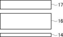
- the backlight 10A shown in FIG. 1 has a configuration in which a patterned cholesteric layer 14 is provided between a substrate 11 (blue light source 12) and a diffuser plate 16, and is located on the opposite side of the diffuser plate 16 from the substrate 11.
- a wavelength conversion sheet 17 is provided. That is, the backlight 10A shown in FIG. 1 has a patterned cholesteric layer 14, a diffuser plate 16, and wavelength conversion from the substrate 11 (blue light source 12) toward the light irradiation direction, as conceptually shown in FIG. 4A.
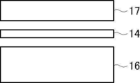
- the sheets 17 are arranged in this order. Further, in the backlight 10B shown in FIG.
- the patterned cholesteric layer 14 is provided on the side opposite to the substrate 11 (blue light source 12) with respect to the diffusion plate 16, and the substrate of the patterned cholesteric layer 14 is provided.
- a wavelength conversion sheet 17 is provided on the opposite side of the 11. That is, the backlight 10B shown in FIG. 2 has a diffuser plate 16, a patterned cholesteric layer 14, and wavelength conversion from the substrate 11 (blue light source 12) toward the light irradiation direction, as conceptually shown in FIG. 4B.
- the sheets 17 are arranged in this order.
- the arrangement order of the patterned cholesteric layer 14, the diffuser plate 16, and the wavelength conversion sheet 17 is not limited to this, and various configurations can be used.
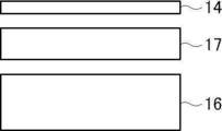
- the diffuser plate 16, the wavelength conversion sheet 17, and the patterned cholesteric layer 14 are arranged in this order from the substrate 11 (blue light source 12) in the light irradiation direction. Is illustrated.
- the patterned cholesteric layer 14, the wavelength conversion sheet 17, and the diffusion plate 16 are arranged in this order from the substrate 11 (blue light source 12) in the light irradiation direction.
- the configuration is illustrated.
- FIG. 4C the diffuser plate 16, the wavelength conversion sheet 17, and the patterned cholesteric layer 14 are arranged in this order from the substrate 11 (blue light source 12) in the light irradiation direction.
- the wavelength conversion sheet 17, the patterned cholesteric layer 14, and the diffusion plate 16 are arranged in this order from the substrate 11 (blue light source 12) in the light irradiation direction.
- the configuration is illustrated.
- the wavelength conversion sheet 17, the diffuser plate 16, and the patterned cholesteric layer 14 are arranged in this order from the substrate 11 (blue light source 12) in the light irradiation direction.
- the configuration is illustrated.
- the substrate 11 is arranged at the lowest position in the drawing.
- the wavelength conversion sheet 17 is provided closer to the blue light source 12 than the patterned cholesteric layer 14. That is, the light after being converted by the wavelength conversion sheet 17 is incident on the patterned cholesteric layer 14. As described above, the portion 14a of the patterned cholesteric layer 14 that overlaps with the blue light source 12 selectively reflects blue light. Therefore, in the configuration in which the wavelength conversion sheet 17 is provided closer to the blue light source 12 than the patterned cholesteric layer 14, the light from the substrate 11 (blue light source 12) is before being homogenized by the patterned cholesteric layer 14.
- the wavelength-converted light (green light and red light) is a pattern. It is less susceptible to the effect of homogenization by the cholesteric layer 14.
- the blue light is often brighter than the wavelength-converted light and can be visually recognized. Easy to do. Therefore, even in a configuration in which the wavelength conversion sheet 17 is provided on the blue light source 12 side of the patterned cholesteric layer 14 as shown in FIGS.
- the portion 14a reflects blue light, the effect of suppressing hot spots and the like and improving the brightness uniformity of the light emitted by the backlight can be sufficiently obtained.
- the backlight of the present invention described above has a patterned cholesteric layer in which the integrated reflectance of the portion superimposed on the blue light source at a wavelength of 450 nm is 30% or more higher than the integrated reflectance of the portion not superimposed on the blue light source at a wavelength of 450 nm. It has.
- Another aspect of the backlight of the present invention has a partial cholesteric film 30 instead of such a patterned cholesteric layer.
- the partial cholesteric film 30 has a sheet-shaped base material 32 and a plurality of circular cholesteric reflecting portions 34 arranged on one surface of the base material 32 so as to be separated from each other.
- the cholesteric reflection unit 34 is provided so as to be superimposed on the blue light source 12, and the selective reflection center wavelength is ⁇ 50 nm of the emission center wavelength of the blue light source 12.
- the cholesteric reflecting portion corresponds to a portion of the above-mentioned patterned cholesteric layer that is superimposed on the blue light source. Further, the partial cholesteric film does not have a cholesteric liquid crystal layer in a region other than the cholesteric reflecting portion. For example, in the case of the patterned cholesteric layer 14 shown in FIGS. 3A to 3D, the portion 14a superimposed on the blue light source 12 becomes the cholesteric reflecting portion, and the portion 14b not superimposed on the blue light source 12 has the cholesteric liquid crystal layer. No, partial cholesteric film is illustrated.
- the material, the forming method, the position, the shape, the area (area), and the like of the cholesteric reflective portion of the partial cholesteric film are basically the same as the portion 14a superimposed on the blue light source in the above-mentioned patterned cholesteric layer. It is a thing.
- examples of the base material include the support in the above-mentioned patterned cholesteric layer, the support on which the base layer is formed, and the like.
- the partial cholesteric film is formed by forming a cholesteric reflecting portion on such a base material according to the arrangement of a blue light source.
- the cholesteric reflecting portion corresponds to a portion of the above-mentioned patterned cholesteric layer that is superimposed on the blue light source. Therefore, the backlight of the present invention using this partially cholesteric film can also irradiate light with high brightness uniformity (plane illumination) by the same action and effect as the backlight having the patterned cholesteric layer described above, and is blue. The utilization efficiency of the light emitted by the light source is also high.
- the selective reflection center wavelength of the cholesteric reflection portion may be ⁇ 50 nm of the emission center wavelength of the blue light source, preferably ⁇ 25 nm, and more preferably coincident.
- the cholesteric reflecting portion preferably has an integrated reflectance at a wavelength of 450 nm of 40 to 100%, more preferably 45 to 80%. It is preferable that the integrated reflectance of the cholesteric reflector at a wavelength of 450 nm is 40 to 100% from the viewpoint of achieving both high luminance uniformity and high light utilization efficiency. Therefore, the thickness of the cholesteric reflecting portion may be appropriately set so that the integrated reflectance at a wavelength of 450 nm is 40 to 100%, depending on the selective reflection center wavelength.
- the cholesteric reflective portion of the partial cholesteric film can be formed in the same manner by using a liquid crystal composition similar to that of the patterned cholesteric layer.
- optical isomerization is not required in the cholesteric reflector. Therefore, it is not necessary to use a chiral agent whose HTP changes by irradiation with light or the like.
- the method of applying the liquid crystal composition in the cholesteric reflective portion of the partial cholesteric film there is no limitation on the method of applying the liquid crystal composition in the cholesteric reflective portion of the partial cholesteric film.
- a plurality of cholesteric reflective portions of the partial cholesteric film are formed by patterning them apart from each other, and as a method for applying the liquid crystal composition, coating by printing is preferably exemplified.
- the printing method of the liquid crystal composition used for forming the cholesteric reflective portion of the partial cholesteric film is not limited, and various known printing methods can be used. Examples of the printing method include gravure printing, offset printing, letterpress printing, inkjet printing, screen printing, and the like.
- a single-sided easy-adhesive single-sided high-smooth PET film (manufactured by Toyobo Co., Ltd., Cosmoshine A4100) having a thickness of 50 ⁇ m was prepared.
- a base layer coating solution having the following composition was applied to the surface of the temporary support on the high smooth layer side with a wire bar coater of # 4.4.
- the obtained coating film was dried at 45 ° C. for 60 seconds, and then the coating film was irradiated with ultraviolet rays of 500 mJ / cm 2 at 25 ° C. by an ultraviolet irradiation device to reduce the film thickness to 1.5 ⁇ m.
- a temporary support having a stratum was prepared.
- Chiral agent L is a chiral agent that forms a left-handed spiral.
- the chiral agent R is a chiral agent that forms a right-handed spiral.
- the chiral agent L and the chiral agent R are chiral agents having a cinnamoyl group, and both have the property of causing isomerization by absorbing UV light and lowering their HTP. Both the chiral agent L and the chiral agent R have an absorption wavelength in the vicinity of 365 nm.
- the numerical value is mass%.
- R is a group bonded with an oxygen atom.
- the average molar extinction coefficient of the rod-shaped liquid crystal compound at a wavelength of 300 to 400 nm was 140 / mol ⁇ cm.
- the prepared coating liquid Ch-L was applied to the surface of the previously prepared base layer A with a wire bar coater of # 6, and dried at 105 ° C. for 60 seconds to obtain a coating film showing blue reflection. Then, in a low oxygen atmosphere (100 volume ppm or less), the light of a high-pressure mercury lamp having an irradiation amount of 30 mJ / cm 2 was irradiated through the exposure mask at 40 ° C. to fix the orientation state of the exposed portion. A partially enlarged view of the exposure mask used at this time is shown in FIG.
- the exposure mask has an opening 41 and a light-shielding portion 42.
- the openings 41 are circular with a diameter of 1 mm, and are arranged in a vertical and horizontal matrix (square grid shape) at intervals of 3 mm at a distance between the centers of the circles.
- the remaining part is a light-shielding part.
- the light of a high-pressure mercury lamp having an irradiation amount of 450 mJ / cm 2 was irradiated to the whole through a short wavelength cut filter (cutoff wavelength 340 nm) at 40 ° C. to perform photoisomerization.
- cutoff wavelength 340 nm short wavelength cut filter
- a layered patterned cholesteric film PL-1 was obtained.
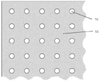
- the appearance of the patterned cholesteric film PL-1 is shown in FIG.
- the patterned cholesteric film PL-1 has a dot portion 51 and a non-dot portion 52 in a shape substantially corresponding to the opening and the non-opening of the exposure mask, the former showing blue reflection and the latter showing dark red reflection. It was.
- the integrated reflectance of the dot portion 51 of the patterned cholesteric film PL-1 at a wavelength of 450 nm was 51%, the center wavelength was 450 nm, and the integrated reflectance of the non-dot portion 52 at a wavelength of 450 nm was 12%, and the center wavelength was 773 nm.
- the prepared coating liquid Ch-L was applied to the surface of the previously formed base layer A with a wire bar coater of # 6, and dried at 105 ° C. for 60 seconds to obtain a coating film showing blue reflection.
- the obtained coating film was irradiated with the light of a high-pressure mercury lamp having an irradiation amount of 500 mJ / cm 2 at 40 ° C. under a low oxygen atmosphere (100 volume ppm or less) to fix the overall orientation state and compare.
- An example full blue cholesteric film L-2 was obtained.
- the integrated reflectance of the all-blue cholesteric film L-2 at a wavelength of 450 nm was 51%, and the center wavelength was 451 nm.
- the prepared coating liquid Ch-R is applied to the surface of the previously prepared patterned cholesteric film PL-1 with a wire bar coater of # 6, and dried at 105 ° C. for 60 seconds to obtain a coating film showing blue reflection. Obtained. Then, in a low oxygen atmosphere (100 volume ppm or less), at 40 ° C., the light of a high-pressure mercury lamp having an irradiation amount of 30 mJ / cm 2 was irradiated through the exposure mask shown in FIG. The state was fixed. At this time, the alignment was performed so that the blue dot portion of the patterned cholesteric film PL-1 and the opening portion of the exposure mask were aligned with each other.
- the light of a high-pressure mercury lamp having an irradiation amount of 450 mJ / cm 2 was irradiated to the whole through a short wavelength cut filter (cutoff wavelength 340 nm) at 40 ° C. to perform photoisomerization.
- the previously exposed portion retains blue reflection, whereas the unexposed portion in the previous step changes its reflection wavelength, resulting in dark red reflection.
- the front surface was irradiated with the light of a high-pressure mercury lamp having an irradiation amount of 500 mJ / cm 2 at 40 ° C.
- a patterned laminated cholesteric film PLR-3 was obtained.
- the appearance of PLR-3 is shown in FIG.
- the patterned laminated cholesteric film PLR-3 has a dot portion 61 and a non-dot portion 62 in a form substantially corresponding to the opening and the non-opening of the exposure mask, the dot portion shows blue reflection, and the non-dot portion is dark. It showed a red reflection.
- the integrated reflectance of the patterned laminated cholesteric film PLR-3 at a wavelength of 450 nm was 96%, the center wavelength was 452 nm, the integrated reflectance of the non-dot portion at a wavelength of 450 nm was 12%, and the center wavelength was 779 nm.
- the prepared coating liquid Ch-R is applied to the surface of the entirely blue cholesteric film L-2 prepared above with a wire bar coater of # 6, and dried at 105 ° C. for 60 seconds to obtain a coating film showing blue reflection. Obtained.
- the obtained coating film was irradiated with the light of a high-pressure mercury lamp having an irradiation amount of 500 mJ / cm 2 at 40 ° C. under a low oxygen atmosphere (100 volume ppm or less) to fix the overall orientation state and compare.
- An example of a fully blue laminated cholesteric film LR-4 was obtained.
- the integrated reflectance of LR-4 at a wavelength of 450 nm was 93%, and the center wavelength was 452 nm.
- patterned cholesteric film PL-1B In the production of the patterned cholesteric film PL-1, the pattern is the same as that of the patterned cholesteric film PL-1, except that the diameter of the opening in the exposure mask used for the exposure of the coating liquid Ch-L is 1.5 mm. A cholesteric film PL-1B was produced.
- patterned cholesteric film PL-1C In the production of the patterned cholesteric film PL-1, the pattern is the same as that of the patterned cholesteric film PL-1, except that the diameter of the opening in the exposure mask used for the exposure of the coating liquid Ch-L is 2.0 mm. A cholesteric film PL-1C was produced.
- patterned laminated cholesteric film PLR-3B (Preparation of patterned laminated cholesteric film PLR-3B)
- the diameter of the opening in the exposure mask used for the exposure of the coating liquid Ch-L was set to 1.5 mm
- the opening in the exposure mask used for the exposure of the coating liquid Ch-R was set to 1.5 mm.
- a patterned laminated cholesteric film PLR-3B was produced in the same manner as the patterned laminated cholesteric film PLR-3 except that the diameter of the film was 1.5 mm.
- patterned laminated cholesteric film PLR-3C (Preparation of patterned laminated cholesteric film PLR-3C)
- the diameter of the opening in the exposure mask used for the exposure of the coating liquid Ch-L was set to 2.0 mm
- the opening in the exposure mask used for the exposure of the coating liquid Ch-R was set to 2.0 mm.
- a patterned laminated cholesteric film PLR-3B was produced in the same manner as the patterned laminated cholesteric film PLR-3 except that the diameter of the film was 2.0 mm.
- a single-sided easy-adhesive single-sided high-smooth PET film (manufactured by Toyobo Co., Ltd., Cosmo Shine A4100) having a thickness of 50 ⁇ m was prepared.
- a base layer coating solution having the following composition was applied to the surface of the temporary support on the high smooth layer side with a wire bar coater of # 4.4.
- the obtained coating film was dried at 45 ° C. for 60 seconds, and then the coating film was irradiated with ultraviolet rays of 500 mJ / cm 2 at 25 ° C. by an ultraviolet irradiation device to reduce the film thickness to 1.5 ⁇ m.
- a temporary support having a stratum was prepared.
- PET30 KAYARAD PET-30 manufactured by Nippon Kayaku Co., Ltd. (mixture of the following two compounds)
- the following chiral agent A was prepared.
- the chiral agent A is a chiral agent that forms a right-handed spiral. Using this chiral agent, a cholesteric reflective portion, which will be described later, was formed.
- Photopolymerization initiator C IRGACURE OXE01 (manufactured by BASF)
- a dot-shaped coating film showing the above was obtained.
- the gravure plate was selected so that the film thickness after drying was 3.0 ⁇ m.
- a UV-LED having a peak at a wavelength of 365 nm is used to irradiate ultraviolet light of 30 mJ / cm 2 at 50 ° C. under air, and a metal halide lamp is used under a low oxygen atmosphere (100 volume ppm or less) at 80 ° C.
- the partial cholesteric film PR-X By irradiating the coating film with ultraviolet light having an irradiation amount of 500 mJ / cm 2 , a partial cholesteric film PR-X as conceptually shown in FIG. 5 was produced.
- the partial cholesteric film PR-X has a circular cholesteric reflecting portion 34 having a diameter of 2 mm and showing a blue color, with an interval of 3 mm between the centers of the circles.
- the integrated reflectance of the cholesteric reflecting portion 34 of the partial cholesteric film PR-X at a wavelength of 450 nm was 48%, the central wavelength was 472 nm, and the integrated reflectance of the portion without the cholesteric reflecting portion 34 at a wavelength of 450 nm was 10%.
- cholesteric films PL-1 (Example 1), PL-1B (Example 2), PL1-C (Example 3), PLR-3 (Example 4), PLR-3B (Example 5), PLR-3C (Example 6), PR-X (Example 7), L-2 (Comparative Example 2), and LR-4 (Comparative Example 3) were transcribed.
- a diffuser plate that does not transfer the cholesteric film was also produced (Comparative Example 1). The transfer was carried out by laminating the produced cholesteric film on a diffusion plate via OCA (Soken Chemical Co., Ltd., SK2557), and then peeling off the temporary support.
- OCA Soken Chemical Co., Ltd., SK2557
- the cholesteric films PL-1 (Example 1) to PLR-3C (Example 6) are aligned so that the center of the dot portion 51 of the cholesteric film overlaps the center (optical axis) of the blue light source of the substrate. It was. Therefore, the dot portion 51 of the cholesteric film corresponds to the “portion superimposing on the blue light source”, and the non-dot portion 52 corresponds to the “portion not superimposing on the blue light source of the patterned cholesteric layer”.
- PR-X Example 7
- the center of the circular cholesteric reflecting portion was aligned so as to overlap the center (optical axis) of the blue light source of the substrate.
- a diffuser plate to which the cholesteric film was transferred was arranged so that the blue light source and the cholesteric film faced each other.
- Wavelength conversion sheet (3M, QDEF-360), two prism sheets (3M, BEF2-T-155n), reflective polarizing element layer (3M) on the diffuser plate (opposite to the blue light source) , BEF-D2-400) were arranged in this order to prepare a backlight for evaluation.
- the two prism sheets were arranged so that the linear prism arrays were orthogonal to each other. Therefore, this example has a cholesteric film, a diffuser plate, and a wavelength conversion sheet in this order in the direction of light emission from the blue light source (see FIG. 4A).
- Example 8 to 14 Comparative Examples 4 to 5
- An evaluation backlight was produced in the same manner as in Examples 1 to 7 and Comparative Examples 2 to 3 except that the diffuser plate to which the cholesteric film was transferred was arranged so that the blue light source and the diffuser plate faced each other. Therefore, this example has a diffuser, a cholesteric film, and a wavelength conversion sheet in this order in the direction of light emission from the blue light source (see FIG. 4B).
- Examples 15 to 21, Comparative Examples 6 to 7 The cholesteric film was similarly transferred to the wavelength conversion sheet. Examples except that the blue light source and the diffuser plate are arranged facing each other, and the wavelength conversion sheet to which the cholesteric film is transferred is arranged on the opposite side of the diffuser plate from the blue light source, except that the wavelength conversion sheet is arranged toward the diffuser plate. Evaluation backlights were produced in the same manner as in 1 to 7 and Comparative Examples 2 to 3. Therefore, this example has a diffuser, a wavelength conversion sheet, and a cholesteric film in this order in the direction of light emission from the blue light source (see FIG. 4C).
- Example 22 to 28, Comparative Examples 8 to 10 The cholesteric film was similarly transferred to the wavelength conversion sheet.
- a backlight for evaluation was produced in the same manner as in 3 to 3. Therefore, this example has a cholesteric film, a wavelength conversion sheet, and a diffuser in this order in the direction of light emission from the blue light source (see FIG. 4D). Further, in this example, an evaluation backlight having no cholesteric film was also produced (Comparative Example 8).
- Examples 29 to 35, Comparative Examples 11 to 12 Examples 1 to 7 and Examples 1 to 7 and the same except that the wavelength conversion sheet was arranged facing the blue light source and the diffuser on which the cholesteric film was transferred was arranged so that the cholesteric film was placed between the wavelength conversion sheet and the diffuser.
- An evaluation backlight was produced in the same manner as in Comparative Examples 2 and 3. Therefore, this example has a wavelength conversion sheet, a cholesteric film, and a diffuser in this order in the direction of light emission from the blue light source (see FIG. 4E).
- Examples 36 to 42, Comparative Examples 13 to 14 Examples 1 to 7 and Examples 1 to 7 and the same except that the wavelength conversion sheet was arranged facing the blue light source and the diffuser plate to which the cholesteric film was transferred was arranged so that the diffuser plate was arranged between the wavelength conversion sheet and the cholesteric film.
- An evaluation backlight was produced in the same manner as in Comparative Examples 2 and 3. Therefore, this example has a wavelength conversion sheet, a diffuser plate, and a cholesteric film diffuser plate in this order in the direction of light emission from the blue light source (see FIG. 4F).
- the evaluation judgment of the light utilization efficiency was performed according to the following criteria. A: 95% or more. B: 85% or more and less than 95%. It gets a little dark, but acceptable. C (NG): Less than 85%. It's too dark and unacceptable.
- the reflectance and the pattern of the portion having the cholesteric film but overlapping with the blue light source of the cholesteric film (Comparative Example 1 and Comparative Example 8) or the pattern cholesteric layer at a wavelength of 450 nm.
- the configuration (Comparative Examples 2 to 7, Comparative Examples 9 to 14) in which the reflectance of the portion of the cholesteric layer not superimposed on the blue light source is the same at a wavelength of 450 nm, either the light utilization efficiency or the uniformity is NG. ..
- the reflectance of the portion of the patterned cholesteric layer superimposed on the blue light source at a wavelength of 450 nm and the reflectance of the portion of the patterned cholesteric layer not superimposed on the blue light source at a wavelength of 450 nm In the configuration using a cholesteric film having a different reflectance and a partial cholesteric film in which a cholesteric reflective layer having a selective reflection center wavelength of ⁇ 50 nm of the emission center wavelength of a blue light source is formed on a base material, the light utilization efficiency and uniformity are achieved. A backlight that is excellent in both sexes can be obtained. Further, as shown in Examples 1 to 42, according to the backlight of the present invention, good light utilization efficiency and brightness uniformity can be realized regardless of the stacking order of the cholesteric film, the diffuser plate and the wavelength conversion sheet.
- Example 43 to 45 ⁇ Making an evaluation backlight with a protective film on a blue light source> Blue LEDs having a emission center wavelength of 450 nm were mounted on a glass epoxy substrate having a size of 100 mm ⁇ 100 mm in 30 rows vertically and horizontally at intervals of 3 mm at the center to prepare a substrate for evaluation. A white solder resist was used for mounting. A silicone resin (refractive index 1.4) was applied onto the mounted substrate to form a transparent protective layer having a thickness of 0.3 mm.
- the above-mentioned cholesteric films PL1-C (Example 43), PLR-3 (Example 44), and PR-X (Example 45) were transferred to the side.
- the above transfer was carried out by laminating the produced cholesteric film on a diffusion plate via an adhesive layer (OCA, manufactured by Soken Chemical Co., Ltd., SK2057), and then peeling off the temporary support of the cholesteric film.
- the diffuser plate to which the cholesteric film was transferred was arranged so that the diffuser plate side faces the protective film side of the substrate having the protective film.
- Wavelength conversion sheet (3M, QDEF-360), two prism sheets (3M, BEF2-T-155n), reflective polarizer layer (3M, DBEF-D2-400) on a cholesteric film.
- the two prism sheets were arranged so that the linear prism arrays were orthogonal to each other. Therefore, this example has a diffuser, a cholesteric film, and a wavelength conversion sheet in this order in the direction of light emission from the blue light source (see FIG. 9A).
- Example 46 Substrates having a protective film were produced in the same manner as in Examples 43 to 45.
- a 1 mm thick single-sided smooth single-sided mat diffuser (Aroma Bright KT-1070B, manufactured by Nippon Polyester Co., Ltd.) was placed on the substrate after the protective film was attached so that the matte surface was on the surface.
- the transfer was carried out by laminating the produced cholesteric film on a wavelength conversion sheet via an adhesive layer (OCA, manufactured by Soken Chemical Co., Ltd., SK2057), and then peeling off the temporary support of the cholesteric film.
- the wavelength conversion sheet to which the cholesteric film was transferred was arranged so that the diffuser plate and the cholesteric film faced each other.
- Two prism sheets (3M, BEF2-T-155n) and a reflective polarizer layer (3M, DBEF-D2-400) are placed on the wavelength conversion sheet (opposite to the blue light source) in this order. It was placed and a backlight for evaluation was prepared.
- the two prism sheets were arranged so that the linear prism arrays were orthogonal to each other.
- This example has a diffuser, a cholesteric film, and a wavelength conversion sheet in this order in the direction of light emission from the blue light source. Further, the cholesteric film is transferred to the wavelength conversion sheet (see FIG. 9B).
- Example 49 to 51 (Preparation of patterned cholesteric film PL-1D)
- a pattern is formed in the same manner as the patterned cholesteric film PL-1C except that a double-sided easy-adhesive PET film (manufactured by Toyobo Co., Ltd., Cosmoshine A4300) having a thickness of 75 ⁇ m is used as a support.
- a cholesteric film PL-1D was produced.
- a partial cholesteric film is produced in the same manner as the partial cholesteric film PR-X except that a double-sided easy-adhesive PET film (manufactured by Toyobo Co., Ltd., Cosmoshine A4300) having a thickness of 75 ⁇ m is used as a support.
- PR-X2 was prepared.
- Substrates having a protective film were produced in the same manner as in Examples 43 to 45.
- a 1 mm thick single-sided smooth single-sided mat diffuser (Aroma Bright KT-1070B, manufactured by Nippon Polyester Co., Ltd.) was placed on the substrate after the protective film was attached.
- cholesteric films PL1-D (Example 49), PLR-3D (Example 50), PR-X2 (Example 51) were placed on a wavelength conversion sheet (QDEF-360 manufactured by 3M) according to the level shown in Table 7. ) was bonded via an adhesive layer (OCA, manufactured by Soken Chemical Co., Ltd., SK2057).
- OCA manufactured by Soken Chemical Co., Ltd., SK2057
- the support side of the cholesteric film produced at the time of bonding was bonded onto a wavelength conversion sheet, and used in the subsequent steps while leaving the support.
- a wavelength conversion sheet to which a cholesteric film was attached was arranged so that the diffuser plate and the cholesteric film faced each other.
- Two prism sheets (3M, BEF2-T-155n) and a reflective polarizer layer (3M, DBEF-D2-400) are placed on the wavelength conversion sheet (opposite to the blue light source) in this order. It was placed and a backlight for evaluation was prepared.
- the two prism sheets were arranged so that the linear prism arrays were orthogonal to each other.
- This example has a diffuser, a cholesteric film, and a wavelength conversion sheet in this order in the direction of light emission from the blue light source. Further, the cholesteric film is attached to the wavelength conversion sheet via a support (see FIG. 9C).
- a configuration having a protective film on a blue light source can also realize good light utilization efficiency and brightness uniformity.
Landscapes
- Physics & Mathematics (AREA)
- Spectroscopy & Molecular Physics (AREA)
- Engineering & Computer Science (AREA)
- General Engineering & Computer Science (AREA)
- General Physics & Mathematics (AREA)
- Optics & Photonics (AREA)
- Liquid Crystal (AREA)
- Planar Illumination Modules (AREA)
Priority Applications (1)
| Application Number | Priority Date | Filing Date | Title |
|---|---|---|---|
| JP2021551404A JP7242886B2 (ja) | 2019-10-02 | 2020-09-30 | バックライトおよび液晶表示装置 |
Applications Claiming Priority (6)
| Application Number | Priority Date | Filing Date | Title |
|---|---|---|---|
| JP2019182354 | 2019-10-02 | ||
| JP2019-182354 | 2019-10-02 | ||
| JP2020-045374 | 2020-03-16 | ||
| JP2020045374 | 2020-03-16 | ||
| JP2020092318 | 2020-05-27 | ||
| JP2020-092318 | 2020-05-27 |
Publications (1)
| Publication Number | Publication Date |
|---|---|
| WO2021066050A1 true WO2021066050A1 (ja) | 2021-04-08 |
Family
ID=75338099
Family Applications (1)
| Application Number | Title | Priority Date | Filing Date |
|---|---|---|---|
| PCT/JP2020/037261 Ceased WO2021066050A1 (ja) | 2019-10-02 | 2020-09-30 | バックライトおよび液晶表示装置 |
Country Status (2)
| Country | Link |
|---|---|
| JP (1) | JP7242886B2 (https=) |
| WO (1) | WO2021066050A1 (https=) |
Cited By (1)
| Publication number | Priority date | Publication date | Assignee | Title |
|---|---|---|---|---|
| WO2024111170A1 (ja) * | 2022-11-22 | 2024-05-30 | 恵和株式会社 | 光拡散シート、バックライトユニット、液晶表示装置、及び情報機器 |
Citations (3)
| Publication number | Priority date | Publication date | Assignee | Title |
|---|---|---|---|---|
| JP2009540617A (ja) * | 2006-06-12 | 2009-11-19 | スリーエム イノベイティブ プロパティズ カンパニー | 再発光半導体構造体及び反射体を有するled装置 |
| JP2015513187A (ja) * | 2012-03-09 | 2015-04-30 | コーニンクレッカ フィリップス エヌ ヴェ | 色調整可能な発光装置 |
| US20160195768A1 (en) * | 2015-01-07 | 2016-07-07 | Samsung Display Co., Ltd. | Liquid crystal display |
-
2020
- 2020-09-30 WO PCT/JP2020/037261 patent/WO2021066050A1/ja not_active Ceased
- 2020-09-30 JP JP2021551404A patent/JP7242886B2/ja active Active
Patent Citations (3)
| Publication number | Priority date | Publication date | Assignee | Title |
|---|---|---|---|---|
| JP2009540617A (ja) * | 2006-06-12 | 2009-11-19 | スリーエム イノベイティブ プロパティズ カンパニー | 再発光半導体構造体及び反射体を有するled装置 |
| JP2015513187A (ja) * | 2012-03-09 | 2015-04-30 | コーニンクレッカ フィリップス エヌ ヴェ | 色調整可能な発光装置 |
| US20160195768A1 (en) * | 2015-01-07 | 2016-07-07 | Samsung Display Co., Ltd. | Liquid crystal display |
Cited By (2)
| Publication number | Priority date | Publication date | Assignee | Title |
|---|---|---|---|---|
| WO2024111170A1 (ja) * | 2022-11-22 | 2024-05-30 | 恵和株式会社 | 光拡散シート、バックライトユニット、液晶表示装置、及び情報機器 |
| JP2024075290A (ja) * | 2022-11-22 | 2024-06-03 | 恵和株式会社 | 光拡散シート、バックライトユニット、液晶表示装置、及び情報機器 |
Also Published As
| Publication number | Publication date |
|---|---|
| JPWO2021066050A1 (https=) | 2021-04-08 |
| JP7242886B2 (ja) | 2023-03-20 |
Similar Documents
| Publication | Publication Date | Title |
|---|---|---|
| EP2510389B1 (en) | Optical constructions incorporating a light guide and low refractive index films | |
| US10295897B2 (en) | Transparent screen | |
| US20180052264A1 (en) | Transparent screen | |
| US20120026431A1 (en) | Lightguide with optical film containing voids and blacklight for display system | |
| JP6833023B2 (ja) | バックライトユニットおよび液晶表示装置 | |
| JP7190587B2 (ja) | 発光装置 | |
| JP6706982B2 (ja) | 面状照明装置 | |
| JP2022022648A (ja) | 発光装置および液晶表示装置 | |
| CN102478187A (zh) | 显示器背光模块与其制造方法 | |
| JP2016194996A (ja) | バックライト装置および表示装置 | |
| KR101135363B1 (ko) | 광대역 반사형 편광 필름 및 이를 포함하는 광원 장치 | |
| JP6193471B2 (ja) | 投映像表示用部材および投映像表示用部材を含む投映システム | |
| JPWO2015050204A1 (ja) | 投映像表示用ハーフミラーおよび投映像表示システム | |
| JP7242886B2 (ja) | バックライトおよび液晶表示装置 | |
| WO2021020337A1 (ja) | バックライトユニットおよび液晶表示装置 | |
| JP7104803B2 (ja) | 反射シートおよび発光装置 | |
| JP7333263B2 (ja) | 波長選択性反射フィルムおよびバックライトユニット | |
| JP7189170B2 (ja) | 面状照明装置 | |
| JP6404742B2 (ja) | 面光源装置および画像表示装置 | |
| WO2022209954A1 (ja) | 加飾シート、表示装置及び自動車車内用内装 | |
| JP2012141394A (ja) | 液晶表示装置 | |
| WO2020179803A1 (ja) | 有機el画像表示装置およびその製造方法 | |
| KR101155879B1 (ko) | 복합 광학시트 및 그 제조 방법 | |
| WO2022024604A1 (ja) | 光学素子および反射シート | |
| KR20100043529A (ko) | 액정 필름, 그 제조 방법과 액정 필름을 포함하는 광원 어셈블리 및 액정 표시 장치 |
Legal Events
| Date | Code | Title | Description |
|---|---|---|---|
| 121 | Ep: the epo has been informed by wipo that ep was designated in this application |
Ref document number: 20872672 Country of ref document: EP Kind code of ref document: A1 |
|
| ENP | Entry into the national phase |
Ref document number: 2021551404 Country of ref document: JP Kind code of ref document: A |
|
| NENP | Non-entry into the national phase |
Ref country code: DE |
|
| 122 | Ep: pct application non-entry in european phase |
Ref document number: 20872672 Country of ref document: EP Kind code of ref document: A1 |