WO2021065690A1 - 真空圧密浚渫工法と気密載荷函体及び真空圧密浚渫船 - Google Patents
真空圧密浚渫工法と気密載荷函体及び真空圧密浚渫船 Download PDFInfo
- Publication number
- WO2021065690A1 WO2021065690A1 PCT/JP2020/036152 JP2020036152W WO2021065690A1 WO 2021065690 A1 WO2021065690 A1 WO 2021065690A1 JP 2020036152 W JP2020036152 W JP 2020036152W WO 2021065690 A1 WO2021065690 A1 WO 2021065690A1
- Authority
- WO
- WIPO (PCT)
- Prior art keywords
- box
- consolidation
- soil
- vacuum
- airtight
- Prior art date
- Legal status (The legal status is an assumption and is not a legal conclusion. Google has not performed a legal analysis and makes no representation as to the accuracy of the status listed.)
- Ceased
Links
Images




Classifications
-
- B—PERFORMING OPERATIONS; TRANSPORTING
- B63—SHIPS OR OTHER WATERBORNE VESSELS; RELATED EQUIPMENT
- B63B—SHIPS OR OTHER WATERBORNE VESSELS; EQUIPMENT FOR SHIPPING
- B63B21/00—Tying-up; Shifting, towing, or pushing equipment; Anchoring
-
- B—PERFORMING OPERATIONS; TRANSPORTING
- B63—SHIPS OR OTHER WATERBORNE VESSELS; RELATED EQUIPMENT
- B63B—SHIPS OR OTHER WATERBORNE VESSELS; EQUIPMENT FOR SHIPPING
- B63B21/00—Tying-up; Shifting, towing, or pushing equipment; Anchoring
- B63B21/24—Anchors
- B63B21/26—Anchors securing to bed
- B63B21/27—Anchors securing to bed by suction
-
- B—PERFORMING OPERATIONS; TRANSPORTING
- B63—SHIPS OR OTHER WATERBORNE VESSELS; RELATED EQUIPMENT
- B63B—SHIPS OR OTHER WATERBORNE VESSELS; EQUIPMENT FOR SHIPPING
- B63B21/00—Tying-up; Shifting, towing, or pushing equipment; Anchoring
- B63B21/50—Anchoring arrangements or methods for special vessels, e.g. for floating drilling platforms or dredgers
-
- B—PERFORMING OPERATIONS; TRANSPORTING
- B63—SHIPS OR OTHER WATERBORNE VESSELS; RELATED EQUIPMENT
- B63B—SHIPS OR OTHER WATERBORNE VESSELS; EQUIPMENT FOR SHIPPING
- B63B35/00—Vessels or similar floating structures specially adapted for specific purposes and not otherwise provided for
-
- E—FIXED CONSTRUCTIONS
- E02—HYDRAULIC ENGINEERING; FOUNDATIONS; SOIL SHIFTING
- E02F—DREDGING; SOIL-SHIFTING
- E02F3/00—Dredgers; Soil-shifting machines
- E02F3/04—Dredgers; Soil-shifting machines mechanically-driven
- E02F3/88—Dredgers; Soil-shifting machines mechanically-driven with arrangements acting by a sucking or forcing effect, e.g. suction dredgers
Definitions
- the present invention relates to vacuum consolidation, dredging and compacted dredged soil on the seabed, riverbed, and lakebed ground in deepening and maintaining water depth of ship routes and anchorages, and reusing them as materials for landfill and seabed embankment.
- Sediment deposited in the waters of the mouths of large rivers is often soft soil with a large water content.
- the sedimentary soil in the waters of harbors with a large city behind it becomes ultra-soft soil, which is deposited with a large amount of organic matter due to the inflow of domestic wastewater and industrial wastewater.
- the characteristic of soft soil is that the water content is very large, but when organic matter is contained, the water content is very large at 200%, and the surface portion of the surface layer reaches as much as 400%.
- the surface layer is called floating mud and is a fluid cohesive soil with extremely low density.
- Soft soil with a water content that exceeds the liquid limit is fluid cohesive soil that does not form a shape. Whether or not a ship can navigate depends on the depth of the water.
- the vacuum consolidation method has been widely used as a ground improvement method on land, but it is also being used for seabed ground and the like.
- the characteristic of the vacuum consolidation method for the seabed ground is that the airtightness of the loading ground surface is maintained in some way, and atmospheric pressure and water pressure are used for the loading.
- the characteristic of this construction method from the environmental point of view is that the strength of the seabed soil can be increased and the volume can be reduced by consolidation settlement without causing water pollution in the original position. If the water depth of the channel etc. is secured only by consolidation settlement, the water depth maintenance method will be a method that does not generate any dredged soil.
- This is a series of vacuum consolidation and dredging methods.
- This construction method is a steel box type called an airtight loading box, and a device that acts as a consolidation loading and dredging bucket for the ground is used.
- the structure of the airtight loading box is a box-shaped structure with an opening at the bottom, and an airtight water-separated airtight tank and a box tower are attached to the central part of the outer upper surface of the box.
- a thin vacuum tank that communicates with the air-water separation airtight tank is provided on the internal ceiling surface, and a plurality of compartments are formed by dividing the internal ceiling surface by a box partition wall having a drain function immediately below the tank, and on the upper surface of the compartment.
- the work process of the vacuum consolidation dredging method is divided into an installation process in which the airtight loading box is set on the seabed, etc., followed by a consolidation process, a dredging process, and a dredging soil transportation process.
- the dredging process is a process of lifting the filled soil held by the box body from the seabed or the like and extruding it from the box body. This lifting corresponds to loading the dredged soil, and extruding the filled soil corresponds to loading and unloading the dredged soil. Airtightness is ensured when the box is set on the seabed. Then, the seabed soil is filled with an airtight loading box.
- the consolidation progresses so that the strength of the submarine soil is equal to or greater than the strength that can be dredged by the box with the bottom opening, that is, the water content ratio of the submarine cohesive soil to be dredged is below the liquid limit, and in the consolidation process, it is medium.
- the wet unit volume weight of the sufficiently compacted filled soil is about 16 kN / m 3
- the vacuum suction force per unit area by the vacuum pump is 80 kN / m 2 .
- the vacuum suction force is a suction force acting on the upper surface of the filled soil. Therefore, this balance has an integrated condition that the filling soil is integrated. That is, the lifting of the filled soil by the airtight loading box with the bottom opening sucks the upper surface of the filled soil in a vacuum.
- the filling soil needs to have a strength that separates it by its own weight and does not fall.
- the integrated condition of the filled soil is the strength obtained by consolidating the water content ratio of the filled soil to below the liquid limit.
- the characteristic of consolidation progression of ultra-soft soil such as sludge is that if consolidation of several millimeters progresses immediately in a few seconds to a dozen seconds, the subsequent consolidation settlement becomes extremely slow.
- There is a vacuum consolidation dredging method that incorporates a special rapid consolidation that utilizes the characteristics of sludge into the consolidation process.
- Tasks 1 and 3 are paired tasks.
- the vacuum-consolidated dredger of Patent Document 2 uses this as a twin-body type work ship, and the space sandwiched between the twin-body is the installation space for the airtight loading box.
- a soil carrier is pulled in to make it a work space for transshipment of dredged soil.
- Problem 1 is that the soil quality of the dredged soil is diverse, whereas the drain of the conventional airtight loading box has the same structure. If the airtight loading box is treated according to the type of soil as a solution to this, it is necessary to frequently replace the airtight loading box equipped on the vacuum consolidation dredger, and the problem that the large-scale work of Problem 3 frequently occurs. Occurs.
- the outline of the solutions to these problems 1 and 3 is that the airtight loading box is handled according to the type of soil, and the main part of the airtight loading box is a separate / detachable structure. The airtight loading box can be easily replaced on board a vacuum-consolidated dredger.
- the airtight loading box is separated into a box lid and a box tube, and these are made a detachable structure.
- the inner surface of the box lid is a water-permeable plate to form a thin internal airtight tank on the entire surface, and the outer surface of the box lid is provided with an air-water separation airtight tank having an integral structure.
- the inside of the box cylinder is divided by a box partition wall having a drain function to form a plurality of compartments, and the division ratio is determined according to the type of dredged soil.
- the airtight loading box is characterized in that a box tube having a drain function corresponding to each type of dredged soil can be easily replaced.
- a box partition wall having a drain function it is preferable that the surface of the box partition wall is coated with a highly water-repellent filter material.
- the consolidation time of sludge and floating mud is extremely long.
- Problem 2 is the establishment of a reliable consolidation system with a minimum drainage distance instead of the repeated consolidation system.
- the consolidation system of the solution to this is a split consolidation system that shortens the consolidation drainage distance.
- the split consolidation system reduces drainage distance by centimeters.
- the distance between the box partition walls of the airtight loading box is set to 20 cm for double-sided drainage.
- the drainage distance is 10 cm.
- the drainage distance H 10 cm H 2 law in sludge of the primary compaction time of 10 minutes the vacuum boiling compaction When applied, it is 1000 minutes and 16.7 hours.
- the cumulative time for primary consolidation is 100 minutes and 1.67 hours. Install the airtight loading box on the seabed and perform vacuum consolidation for 10 minutes.
- the airtight loading box that can be re-installed in centimeters used in the vacuum consolidation dredging method for ultra-soft soil has a double box structure with a bottom opening.
- the outer box is connected to the lifting device of the airtight loading box of the vacuum consolidation dredger, but it has an opening on the upper surface and is not airtight.
- the opening of this outer box is for a brackish water separation tank that projects above the upper surface of the inner box.
- the inner box is airtight, the height of the box is constantly lower than that of the outer box, the length of the box is constantly short in only one direction, and the upper surface of the inner box is directly below the ceiling surface of the outer box.
- the bottom surface of the inner box is the middle stage inside the outer box, and the inner box cannot move in the vertical direction, and can move for a certain length only in one horizontal direction.
- the height of the inner box is appropriately about 2/3 to 1/2 of the height of the outer box.
- the box body length is shortened by one interval of the box body partition wall.
- a double-acting hydraulic cylinder is preferable as the driving force for moving the internal box.
- the inner box is moved horizontally with the outer box restraining the seabed soil, etc., and the inner box is repositioned according to the position of the division consolidation to restart the vacuum consolidation.
- This is a vacuum consolidation dredging method characterized by systematically shortening the consolidation drainage distance to several centimeters and significantly shortening the consolidation time by a split consolidation system that repeats this process.
- the predetermined consolidation time refers to the primary consolidation time.
- the primary consolidation time for split consolidation is estimated from a consolidation test with clay samples of split thickness.
- the solution to Problem 3 which is paired with Problem 1 is a mechanism in which the airtight loading box can be easily replaced on board a vacuum consolidation dredger.
- the vacuum-consolidated dredger integrates four floating vessels by arranging them on the bow, stern, starboard, and left side while securing an elevating space for the airtight loading box.
- a three-dimensional turret will be installed in the elevating space to attach the elevating device of the airtight loading box, and decks will be installed at the bow and stern.
- One of the decks will be the parking space for the work trolley.
- the work trolley is equipped with a dredging soil bucket during the work of loading and unloading the dredging soil. The work trolley is also used when replacing the box cylinder of the airtight loading box.
- the airtight loading box is pulled up to the highest position, the work space of the work trolley is secured, and the onboard track provided by the work trolley in the overall length direction of the ship and the extension track outside the ship by the extension starter can be freely set.
- It is a vacuum consolidation dredger characterized by a traveling structural form.
- the vertical material of the turret is used as an outer tube for accommodating the multi-stage telescopic columns of the elevating device of the airtight loading box, and operates simultaneously on multiple outer tubes. Insert and attach the downward multi-stage telescopic column.
- the connecting member of the airtight loading box is fixed to the tip of these multi-stage telescopic columns.
- the tip portions of a plurality of multi-stage telescopic columns are rigidly connected by a plurality of girders to form a fixed girder set, and this fixed girder set is for attaching an airtight loading box.
- the vacuum consolidation dredger of the present invention is characterized in that a three-dimensional multi-stage telescopic column and a connecting member integrated with the three-dimensional multi-stage telescopic column are incorporated in an elevating turret of a three-dimensional frame.
- a telescopic method in which a plurality of stages of telescopic columns are sequentially fed by one hydraulic cylinder is preferable.
- the airtight loading box of the present invention is separated into a box lid and a box cylinder, which have a detachable structure.
- the box lid of the airtight loading box is connected to the connecting member of the lifting device.
- Problem 4 is a vacuum-consolidated dredger that can be loaded and unloaded with dredged soil without being limited to a specific soil carrier and can also be landed.
- the solution to this is to use a dedicated soil carrier with a special device (cradle for the extension track) attached to an ordinary soil carrier as an outrigger for a vacuum consolidation dredger.
- the position for loading and unloading the dredging soil of the vacuum consolidation dredging vessel equipped with the airtight loading box is the stop side of the work trolley, and the work trolley is equipped with a dredging soil bucket with a bottom opening structure.
- the vacuum consolidation dredger is equipped with an extension track device that extends the track of the work carriage outboard.
- a cradle with a height adjustment function is attached to a dedicated earth carrier.
- the mounting position of this is on the center line of the floating body on the side of the dedicated earth carrier.
- the track on the deck of the work cart is a hollow box-shaped cross-section track, and a telescopic box girder is inserted into each of the two box-shaped cross-section tracks.
- the telescopic box girder constitutes a composite telescopic girder by fixing the paired tip portions with a horizontal girder.
- cross girders are attached at track intervals in the direction of the ship's belly of the dedicated earth carrier, and hollow columns are fixed to this cross girder on the floating center line of the dedicated earth carrier to expand and contract the height adjustment.
- the vacuum consolidation dredger and the dedicated soil carrier will be temporarily integrated.
- the height of the cradle which is the fulcrum outside the ship, is adjusted.
- the load on the cradle increases when the work cart equipped with the dredged soil bucket moves on the outboard extension track.
- the airtight loading box used for this has a detachable structure of the box lid and the box cylinder corresponding to each type of dredging soil, and only the box cylinder is replaced on board the vacuum consolidation dredger. This has brought about the effect of easily and quickly implementing the response for each type of dredged soil. Further, in the split consolidation system of the present invention, the inner box moves in the horizontal direction in centimeters while the outer box restrains the dredged soil by the airtight loading box having a double box structure, and the consolidation is repeated. This has had the effect of implementing ultra-rapid consolidation.
- the loading and unloading of the dredged soil by the vacuum consolidation dredging vessel of the present invention is provided by providing a function of temporarily integrating with a dedicated dredging vessel in which a cradle for an extension track is attached to a normal dredging vessel and using this as an outrigger.
- the loading and unloading of dredged soil has the effect of being stable and quick.
- FIG. 1 is a side view of the vacuum consolidation dredger of the present invention.
- FIG. 2 is a plan view (cross-sectional view taken along the line AA) of the vacuum consolidation dredger.
- FIG. 3 is a vertical cross-sectional view of an airtight loading box in which the box lid and the box tube of the present invention are detachable.
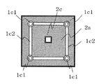
- FIG. 4 is a plan view of the upper surface of the box lid of the airtight loading box.
- FIG. 5 is a vertical sectional view of an airtight loading box having a double box structure of the present invention.
- FIG. 6 is a plan view of the upper surface of the outer box of the airtight loading box.
- FIG. 7 is a side view of the vacuum consolidation dredger of the present invention during the vacuum consolidation process.
- FIG. 8 is a side view of the dredging soil of the vacuum consolidation dredger of the present invention at the time of loading and unloading.
- FIG. 9 is a plan view (cross-sectional view taken along the line BB) of the vacuum consolidation dredger.
- FIG. 1 is a side view of the vacuum consolidation dredger of the present invention, and is an example in which two airtight loading boxes are provided.
- FIG. 2 is a plan view (cross-sectional view taken along the line AA) of the dredger 7.
- 1 is a vacuum consolidation dredger
- 1a is a pontoon
- 1b is a turret for raising and lowering an airtight loading box
- 1b1 is a turret column
- 1b2 is a telescopic column storage outer pipe
- 1b3 is a turret beam
- 1d is an onboard track of a work trolley. Is.
- the dredger 1 includes a trolley 1a, an elevating turret 1b for equipping an airtight loading box, an onboard track 1d on which a work trolley 4 travels, and a work operation building 5.
- the work carriage 4 has traveling wheels fixed to the frame structure.
- the airtight loading box 2 or 3 is divided into two types: a normal dredging box and an ultra-soft dredging box.
- FIG. 3 is a schematic vertical cross-sectional view of the airtight loading box 2 of the present invention in which the box lid and the box body have a detachable structure
- FIG. 3 (a) shows the box lid and the box. The cylinder is in the combined state
- FIG. 4 in the figure is in the separated state.
- FIG. 4 is a plan view of the upper surface of the box lid of the airtight loading box 2.
- 2a is a box lid of the airtight loading box 2
- 2b is a box tube.
- 1c1 is a multi-stage telescopic column
- 1c2 is a connecting member of the airtight loading box 2
- the telescopic column storage outer pipe 1b2 constitutes an elevating device 1c of the airtight loading box.
- FIG. 1c1 is a multi-stage telescopic column
- 1c2 is a connecting member of the airtight loading box 2
- the telescopic column storage outer pipe 1b2 constitutes an elevating device 1
- FIG. 5 is a schematic vertical sectional view of the airtight loading box 3 having a double box structure in the airtight loading box of the present invention
- FIG. 6 is a plan view of the upper surface of the outer box of the airtight loading box 3. is there.
- 3a is an outer box
- 3b is an inner box.
- the air-consolidated loading box 3 is installed at a predetermined position on the seabed to proceed with vacuum consolidation, and when a predetermined consolidation time, for example, a primary consolidation time has elapsed.
- FIG. 7 is a side view of a state in which the airtight loading box 2 or 3 mounted on the vacuum consolidation dredger 1 of the present invention is installed on the seabed.
- the airtight loading box 2 or 3 is connected to the connecting member 1c2, and the multi-stage telescopic column 1c1 is extended and installed on the seabed.
- FIG. 8 is a side view when the dredging soil is loaded and unloaded from the vacuum consolidation dredging vessel 1 of the present invention to a dedicated soil carrier
- FIG. 9 is a plan view (cross-sectional view taken along the line BB).
- 4 is a work cart
- 6 is a dredged soil bucket
- 7 is a dedicated soil carrier
- 1e1 is a stretching track
- 1e2 is a cradle for the stretching track, which constitutes the stretching track device 1e.
- the vacuum consolidation dredger 1 of the present invention when the airtight loading box 2 or 3 is pulled up to the maximum position, the work space of the work carriage 4 is secured, and the onboard track provided by the work carriage 4 in the overall length direction of the ship.
- the dredging soil bucket 6 is mounted on the work cart 4 during the work of loading and unloading the dredging soil.
- the dredging soil bucket 6 in the figure has a bottom-opening structure, and its length is half that of the airtight loading box 2 or 3.
- the method of loading and unloading half of the dredged soil from the airtight loading box to the dredged soil bucket 6 is dealt with by dividing the vacuum consolidation system of the airtight loading box and making it independent.
- the method of loading and unloading the dredged soil is to extend the extension track 1e1 to the outside of the ship on the extension line of the onboard track 1d with the extension track device 1e, and connect it to the cradle 1e2 of the telescopic track attached to the dedicated soil carrier 7 for vacuum compaction.
- the dredger 1 and the dedicated soil carrier 7 are temporarily integrated, and the dedicated soil carrier 7 is used as the out trigger of the vacuum compacted dredger 1.
- the cradle 1e2 of the telescopic track serves as an outboard fulcrum of the vacuum consolidation dredger 1, and is located on the floating center line of the side of the dedicated earth carrier 7 and has a height adjusting function.
- a cradle 1e2 for a telescopic track is attached to a normal soil carrier to form a dedicated soil carrier 7.
- Vacuum compacted dredging ship 1a Platform 1b Lifting turret 1b1 Tower support 1b2 Telescopic column storage outer pipe 1b3 Tower beam 1c Airtight loading box lifting device 1c1 Multi-stage telescopic column 1c2 Airtight loading box connecting member 1c Equipment 1e1 Stretched track 1e2 Stretched track cradle 2 Airtight loading box 2a Same box lid 2b Same box cylinder 2c Air-tight separation airtight tank 3 Double box structure airtight loading box 3a Same external box 3b Same inside Box 4 Work trolley 5 Work operation building 6 Consolidation bucket 7 Dedicated soil carrier 8 Sea surface 9 Submarine ground (submarine soil)
Landscapes
- Engineering & Computer Science (AREA)
- Mechanical Engineering (AREA)
- Chemical & Material Sciences (AREA)
- Combustion & Propulsion (AREA)
- Ocean & Marine Engineering (AREA)
- Mining & Mineral Resources (AREA)
- Civil Engineering (AREA)
- General Engineering & Computer Science (AREA)
- Structural Engineering (AREA)
- Investigation Of Foundation Soil And Reinforcement Of Foundation Soil By Compacting Or Drainage (AREA)
Priority Applications (1)
| Application Number | Priority Date | Filing Date | Title |
|---|---|---|---|
| JP2021551169A JP7324966B2 (ja) | 2019-10-03 | 2020-09-16 | 真空圧密浚渫工法と気密載荷函体及び真空圧密浚渫船 |
Applications Claiming Priority (2)
| Application Number | Priority Date | Filing Date | Title |
|---|---|---|---|
| JP2019192294 | 2019-10-03 | ||
| JP2019-192294 | 2019-10-03 |
Publications (1)
| Publication Number | Publication Date |
|---|---|
| WO2021065690A1 true WO2021065690A1 (ja) | 2021-04-08 |
Family
ID=75337346
Family Applications (1)
| Application Number | Title | Priority Date | Filing Date |
|---|---|---|---|
| PCT/JP2020/036152 Ceased WO2021065690A1 (ja) | 2019-10-03 | 2020-09-16 | 真空圧密浚渫工法と気密載荷函体及び真空圧密浚渫船 |
Country Status (2)
| Country | Link |
|---|---|
| JP (1) | JP7324966B2 (https=) |
| WO (1) | WO2021065690A1 (https=) |
Cited By (1)
| Publication number | Priority date | Publication date | Assignee | Title |
|---|---|---|---|---|
| CN113882448A (zh) * | 2021-09-24 | 2022-01-04 | 中交第一公路勘察设计研究院有限公司 | 一种河道箱涵/暗涵清淤的方法 |
Citations (3)
| Publication number | Priority date | Publication date | Assignee | Title |
|---|---|---|---|---|
| JPS5513326A (en) * | 1978-07-12 | 1980-01-30 | Katsuyoshi Harada | Dredging method and dredge boat |
| JPS57118989A (en) * | 1980-11-11 | 1982-07-24 | Ihc Holland Nv | Floating device |
| WO2017159692A1 (ja) * | 2016-03-18 | 2017-09-21 | 正佳 近藤 | 真空圧密浚渫工法とタワー式気密載荷函体及び専用作業船 |
-
2020
- 2020-09-16 WO PCT/JP2020/036152 patent/WO2021065690A1/ja not_active Ceased
- 2020-09-16 JP JP2021551169A patent/JP7324966B2/ja active Active
Patent Citations (3)
| Publication number | Priority date | Publication date | Assignee | Title |
|---|---|---|---|---|
| JPS5513326A (en) * | 1978-07-12 | 1980-01-30 | Katsuyoshi Harada | Dredging method and dredge boat |
| JPS57118989A (en) * | 1980-11-11 | 1982-07-24 | Ihc Holland Nv | Floating device |
| WO2017159692A1 (ja) * | 2016-03-18 | 2017-09-21 | 正佳 近藤 | 真空圧密浚渫工法とタワー式気密載荷函体及び専用作業船 |
Cited By (1)
| Publication number | Priority date | Publication date | Assignee | Title |
|---|---|---|---|---|
| CN113882448A (zh) * | 2021-09-24 | 2022-01-04 | 中交第一公路勘察设计研究院有限公司 | 一种河道箱涵/暗涵清淤的方法 |
Also Published As
| Publication number | Publication date |
|---|---|
| JP7324966B2 (ja) | 2023-08-14 |
| JPWO2021065690A1 (https=) | 2021-04-08 |
Similar Documents
| Publication | Publication Date | Title |
|---|---|---|
| JP6582361B2 (ja) | 真空圧密浚渫工法とタワー式気密載荷函体及び専用作業船。 | |
| KR101327476B1 (ko) | 대용량 해저저장탱크 및 그의 제작 및 설치방법 | |
| US11739497B2 (en) | Amphibious platform vehicle-vessel | |
| JP2020180544A (ja) | 海底資源収集の装置および方法 | |
| US2973046A (en) | Apparatus for offshore recovery and storage of oil and the like | |
| CN101858083A (zh) | 低空间水中钢管桩拔桩施工方法及装置 | |
| WO2021169195A1 (zh) | 适用于浅水粘性海床的底边界层原位观测系统与其布设方法 | |
| US8522459B2 (en) | Submergible densification cell, sediment separator and sediment densification method | |
| CN113833044A (zh) | 高精度的环保型沉管基床清淤平台 | |
| WO2021065690A1 (ja) | 真空圧密浚渫工法と気密載荷函体及び真空圧密浚渫船 | |
| MX2007003412A (es) | Solucion de mineria para reflotacion y colocacion de una estructura de flotacion mar adentro. | |
| CN100473440C (zh) | 用于悬浊液分离的分离流路模块、分离单元与分离船 | |
| JP2003261930A (ja) | 水底軟弱地盤の圧密改良工法 | |
| NL1001731C2 (nl) | Werkwijze voor het onttrekken van een vloeistof aan een mengsel. | |
| RU2702470C1 (ru) | Способ производства промысловых работ на глубоководном шельфе | |
| RU2710876C1 (ru) | Судоподъемный модульный комплекс-док | |
| KR101052834B1 (ko) | 준설 및 항타 겸용 바지선 그리고 이의 사용 방법 | |
| JP2002018499A (ja) | 泥水の脱水処理台船 | |
| JP4341772B2 (ja) | 浚渫方法及び浚渫システム | |
| RU2479460C1 (ru) | Способ подъема затонувшего судна и комплекс для подъема и транспортирования затонувших подводных лодок и других судов | |
| WO2019187169A1 (ja) | 真空圧密浚渫工法とタワー式気密載荷函体及び専用作業船 | |
| JP2025161678A (ja) | 真空バケット浚渫工法と真空バケット及び真空バケット浚渫船 | |
| RU2818871C1 (ru) | Устройство для глубоководной добычи илистых отложений и очистки водоемов | |
| JP2023129165A (ja) | 深海底の堆積資源物の採掘・引上げ・湿式製錬・残泥処理工法と資源採取バケット,圧力増減タンク,湿式製錬圧密槽及び資源採掘船 | |
| JP2026050288A (ja) | 急速真空圧密工法による底質改良工法と気密載荷函体及び覆砂造成工法と覆砂設置函体 |
Legal Events
| Date | Code | Title | Description |
|---|---|---|---|
| 121 | Ep: the epo has been informed by wipo that ep was designated in this application |
Ref document number: 20872755 Country of ref document: EP Kind code of ref document: A1 |
|
| ENP | Entry into the national phase |
Ref document number: 2021551169 Country of ref document: JP Kind code of ref document: A |
|
| NENP | Non-entry into the national phase |
Ref country code: DE |
|
| 122 | Ep: pct application non-entry in european phase |
Ref document number: 20872755 Country of ref document: EP Kind code of ref document: A1 |