WO2021065175A1 - 処理装置、電子機器、処理方法、及びプログラム - Google Patents
処理装置、電子機器、処理方法、及びプログラム Download PDFInfo
- Publication number
- WO2021065175A1 WO2021065175A1 PCT/JP2020/028909 JP2020028909W WO2021065175A1 WO 2021065175 A1 WO2021065175 A1 WO 2021065175A1 JP 2020028909 W JP2020028909 W JP 2020028909W WO 2021065175 A1 WO2021065175 A1 WO 2021065175A1
- Authority
- WO
- WIPO (PCT)
- Prior art keywords
- imaging
- image
- light
- reflectance
- distance measurement
- Prior art date
- Legal status (The legal status is an assumption and is not a legal conclusion. Google has not performed a legal analysis and makes no representation as to the accuracy of the status listed.)
- Ceased
Links
Images















Classifications
-
- G—PHYSICS
- G01—MEASURING; TESTING
- G01S—RADIO DIRECTION-FINDING; RADIO NAVIGATION; DETERMINING DISTANCE OR VELOCITY BY USE OF RADIO WAVES; LOCATING OR PRESENCE-DETECTING BY USE OF THE REFLECTION OR RERADIATION OF RADIO WAVES; ANALOGOUS ARRANGEMENTS USING OTHER WAVES
- G01S17/00—Systems using the reflection or reradiation of electromagnetic waves other than radio waves, e.g. lidar systems
- G01S17/88—Lidar systems specially adapted for specific applications
- G01S17/89—Lidar systems specially adapted for specific applications for mapping or imaging
- G01S17/894—Three-dimensional [3D] imaging with simultaneous measurement of time-of-flight at a two-dimensional [2D] array of receiver pixels, e.g. time-of-flight cameras or flash lidar
-
- G—PHYSICS
- G01—MEASURING; TESTING
- G01S—RADIO DIRECTION-FINDING; RADIO NAVIGATION; DETERMINING DISTANCE OR VELOCITY BY USE OF RADIO WAVES; LOCATING OR PRESENCE-DETECTING BY USE OF THE REFLECTION OR RERADIATION OF RADIO WAVES; ANALOGOUS ARRANGEMENTS USING OTHER WAVES
- G01S17/00—Systems using the reflection or reradiation of electromagnetic waves other than radio waves, e.g. lidar systems
- G01S17/88—Lidar systems specially adapted for specific applications
- G01S17/89—Lidar systems specially adapted for specific applications for mapping or imaging
-
- G—PHYSICS
- G01—MEASURING; TESTING
- G01B—MEASURING LENGTH, THICKNESS OR SIMILAR LINEAR DIMENSIONS; MEASURING ANGLES; MEASURING AREAS; MEASURING IRREGULARITIES OF SURFACES OR CONTOURS
- G01B11/00—Measuring arrangements characterised by the use of optical techniques
- G01B11/14—Measuring arrangements characterised by the use of optical techniques for measuring distance or clearance between spaced objects or spaced apertures
-
- G—PHYSICS
- G01—MEASURING; TESTING
- G01S—RADIO DIRECTION-FINDING; RADIO NAVIGATION; DETERMINING DISTANCE OR VELOCITY BY USE OF RADIO WAVES; LOCATING OR PRESENCE-DETECTING BY USE OF THE REFLECTION OR RERADIATION OF RADIO WAVES; ANALOGOUS ARRANGEMENTS USING OTHER WAVES
- G01S17/00—Systems using the reflection or reradiation of electromagnetic waves other than radio waves, e.g. lidar systems
- G01S17/02—Systems using the reflection of electromagnetic waves other than radio waves
- G01S17/06—Systems determining position data of a target
- G01S17/42—Simultaneous measurement of distance and other co-ordinates
-
- G—PHYSICS
- G01—MEASURING; TESTING
- G01S—RADIO DIRECTION-FINDING; RADIO NAVIGATION; DETERMINING DISTANCE OR VELOCITY BY USE OF RADIO WAVES; LOCATING OR PRESENCE-DETECTING BY USE OF THE REFLECTION OR RERADIATION OF RADIO WAVES; ANALOGOUS ARRANGEMENTS USING OTHER WAVES
- G01S17/00—Systems using the reflection or reradiation of electromagnetic waves other than radio waves, e.g. lidar systems
- G01S17/86—Combinations of lidar systems with systems other than lidar, radar or sonar, e.g. with direction finders
-
- G—PHYSICS
- G01—MEASURING; TESTING
- G01S—RADIO DIRECTION-FINDING; RADIO NAVIGATION; DETERMINING DISTANCE OR VELOCITY BY USE OF RADIO WAVES; LOCATING OR PRESENCE-DETECTING BY USE OF THE REFLECTION OR RERADIATION OF RADIO WAVES; ANALOGOUS ARRANGEMENTS USING OTHER WAVES
- G01S7/00—Details of systems according to groups G01S13/00, G01S15/00, G01S17/00
- G01S7/48—Details of systems according to groups G01S13/00, G01S15/00, G01S17/00 of systems according to group G01S17/00
- G01S7/483—Details of pulse systems
- G01S7/486—Receivers
- G01S7/4868—Controlling received signal intensity or exposure of sensor
-
- G—PHYSICS
- G03—PHOTOGRAPHY; CINEMATOGRAPHY; ANALOGOUS TECHNIQUES USING WAVES OTHER THAN OPTICAL WAVES; ELECTROGRAPHY; HOLOGRAPHY
- G03B—APPARATUS OR ARRANGEMENTS FOR TAKING PHOTOGRAPHS OR FOR PROJECTING OR VIEWING THEM; APPARATUS OR ARRANGEMENTS EMPLOYING ANALOGOUS TECHNIQUES USING WAVES OTHER THAN OPTICAL WAVES; ACCESSORIES THEREFOR
- G03B13/00—Viewfinders; Focusing aids for cameras; Means for focusing for cameras; Autofocus systems for cameras
- G03B13/18—Focusing aids
- G03B13/20—Rangefinders coupled with focusing arrangements, e.g. adjustment of rangefinder automatically focusing camera
-
- G—PHYSICS
- G03—PHOTOGRAPHY; CINEMATOGRAPHY; ANALOGOUS TECHNIQUES USING WAVES OTHER THAN OPTICAL WAVES; ELECTROGRAPHY; HOLOGRAPHY
- G03B—APPARATUS OR ARRANGEMENTS FOR TAKING PHOTOGRAPHS OR FOR PROJECTING OR VIEWING THEM; APPARATUS OR ARRANGEMENTS EMPLOYING ANALOGOUS TECHNIQUES USING WAVES OTHER THAN OPTICAL WAVES; ACCESSORIES THEREFOR
- G03B13/00—Viewfinders; Focusing aids for cameras; Means for focusing for cameras; Autofocus systems for cameras
- G03B13/32—Means for focusing
- G03B13/34—Power focusing
- G03B13/36—Autofocus systems
-
- H—ELECTRICITY
- H04—ELECTRIC COMMUNICATION TECHNIQUE
- H04N—PICTORIAL COMMUNICATION, e.g. TELEVISION
- H04N23/00—Cameras or camera modules comprising electronic image sensors; Control thereof
- H04N23/56—Cameras or camera modules comprising electronic image sensors; Control thereof provided with illuminating means
-
- H—ELECTRICITY
- H04—ELECTRIC COMMUNICATION TECHNIQUE
- H04N—PICTORIAL COMMUNICATION, e.g. TELEVISION
- H04N23/00—Cameras or camera modules comprising electronic image sensors; Control thereof
- H04N23/60—Control of cameras or camera modules
- H04N23/61—Control of cameras or camera modules based on recognised objects
-
- H—ELECTRICITY
- H04—ELECTRIC COMMUNICATION TECHNIQUE
- H04N—PICTORIAL COMMUNICATION, e.g. TELEVISION
- H04N23/00—Cameras or camera modules comprising electronic image sensors; Control thereof
- H04N23/60—Control of cameras or camera modules
- H04N23/63—Control of cameras or camera modules by using electronic viewfinders
-
- H—ELECTRICITY
- H04—ELECTRIC COMMUNICATION TECHNIQUE
- H04N—PICTORIAL COMMUNICATION, e.g. TELEVISION
- H04N23/00—Cameras or camera modules comprising electronic image sensors; Control thereof
- H04N23/60—Control of cameras or camera modules
- H04N23/667—Camera operation mode switching, e.g. between still and video, sport and normal or high- and low-resolution modes
-
- H—ELECTRICITY
- H04—ELECTRIC COMMUNICATION TECHNIQUE
- H04N—PICTORIAL COMMUNICATION, e.g. TELEVISION
- H04N23/00—Cameras or camera modules comprising electronic image sensors; Control thereof
- H04N23/60—Control of cameras or camera modules
- H04N23/67—Focus control based on electronic image sensor signals
- H04N23/671—Focus control based on electronic image sensor signals in combination with active ranging signals, e.g. using light or sound signals emitted toward objects
-
- H—ELECTRICITY
- H04—ELECTRIC COMMUNICATION TECHNIQUE
- H04N—PICTORIAL COMMUNICATION, e.g. TELEVISION
- H04N23/00—Cameras or camera modules comprising electronic image sensors; Control thereof
- H04N23/70—Circuitry for compensating brightness variation in the scene
- H04N23/74—Circuitry for compensating brightness variation in the scene by influencing the scene brightness using illuminating means
Definitions
- the technology of the present disclosure relates to processing equipment, electronic devices, processing methods, and programs.
- Patent No. 632145 discloses a distance measuring device.
- the distance measuring device according to Patent No. 6321145 includes an imaging unit that captures an image of a subject imaged by an imaging optical system that forms an image of a subject indicating the subject, and an imaging unit along the optical axis direction of the imaging optical system.
- An ejection unit that emits directional light, which is directional light, and the emission intensity of the directional light can be adjusted, and at least the focusing state identification information and the subject brightness or exposure state identification information.
- An emission unit that emits directional light by adjusting the emission intensity based on one side, a light receiving unit that receives reflected light from the subject of the directional light, and a timing and light receiving unit that emits directional light by the emission unit.
- At least one of the derivation unit that derives the distance to the subject based on the timing at which the reflected light is received and the focus adjustment and the exposure adjustment of the imaging optical system to the subject are executed prior to the shooting by the photographing unit.
- the executing unit controls that at least one of the focus adjustment and the exposure adjustment is executed, and at least one of the focus adjustment and the exposure adjustment.
- the photographing unit Includes a control unit that controls the main exposure by.
- Japanese Patent Application Laid-Open No. 2006-171120 discloses a photographing apparatus.
- the photographing apparatus described in Japanese Patent Application Laid-Open No. 2006-171120 is an imaging apparatus that detects subject contrast and adjusts focus prior to an imaging operation, and has a relatively wide wavelength band toward the subject for subject contrast detection.
- the light emission control device described in Patent Document 3 includes a light amount setting unit that sets the amount of AF (Auto Focus) auxiliary light, and a light emission control unit that controls the light emission of AF auxiliary light according to the setting by the light amount setting unit. ing.
- One embodiment according to the technique of the present disclosure is for distance measurement with respect to the image in the imaging region, as compared with the case where the irradiation energy of the light emitted for distance measurement is determined independently of the reflectance in the imaging region.
- the first aspect according to the technique of the present disclosure is an imaging operation by an imaging unit that images an imaging region, and a distance measuring unit irradiates the imaging region with light and receives reflected light from the light on the imaging region.
- a control unit that controls the distance measurement operation that performs distance measurement, an acquisition unit that acquires reflectance information that can specify the reflectance in the imaging region, and an imaging operation and a distance measurement operation are performed.
- It is a processing device including a changing unit that changes the irradiation energy of light according to the reflectance information acquired by the acquiring unit in the state.
- the second aspect according to the technique of the present disclosure is the processing apparatus according to the first aspect, wherein the reflectance information is information based on an image pickup area image obtained by imaging the image pickup area by an image pickup unit. ..
- the third aspect according to the technique of the present disclosure is the process according to the second aspect, in which the information based on the image pickup area image is an image recognition result obtained by performing image recognition on the image pickup area image by the recognition unit. It is a device.
- a fourth aspect of the technique of the present disclosure is a third aspect in which the acquisition unit acquires an image recognition result based on the learning result obtained by machine learning the correspondence between the image and the subject recognition result. It is a processing apparatus according to an aspect.
- a fifth aspect according to the technique of the present disclosure is a case where the image recognition result acquired by the acquisition unit is an image recognition result indicating that the image in the imaging region image includes an image showing an object having a reference reflectance or more.
- the changing part is the processing apparatus according to the third aspect or the fourth aspect, which makes the irradiation energy weaker than the first reference irradiation energy.
- the sixth aspect according to the technique of the present disclosure is the processing apparatus according to the fifth aspect, wherein the object is an object predetermined as a glossy object.
- the seventh aspect according to the technique of the present disclosure is the processing apparatus according to the sixth aspect, wherein the predetermined object is a mirror-like object.
- An eighth aspect according to the technique of the present disclosure is the imaging scene instruction information received by the reception unit capable of receiving the imaging scene instruction information instructing the imaging scene by the changing unit, and the reflectance information acquired by the acquisition unit.
- the processing apparatus according to any one of the first to seventh aspects, which changes the irradiation energy of light according to the above.
- a ninth aspect according to the technique of the present disclosure is a case where the modification unit is a specific imaging scene in which the imaging scene instructed by the imaging scene instruction information received by the reception unit has an imaging scene reflectance equal to or higher than the reference reflectance.
- it is a processing apparatus according to an eighth aspect, which makes the irradiation energy weaker than the second reference irradiation energy.
- a tenth aspect according to the technique of the present disclosure corresponds to an imaging scene specified by a specific unit capable of identifying an imaging scene based on an imaging region image and a reflectance information acquired by the acquisition unit.
- the processing apparatus according to any one of the first to seventh aspects, which changes the irradiation energy of light.
- the irradiation energy is set as the third reference.
- the processing apparatus according to the tenth aspect which is weaker than the irradiation energy.
- control unit controls to generate auxiliary light as light from the light source and to receive the auxiliary reflected light by the auxiliary light for the imaging region to the light receiving element, and the reflectance information.
- processing device Is the processing device according to any one of the first to eleventh aspects, which is information based on the light receiving result of the auxiliary reflected light received by the light receiving element.
- the thirteenth aspect according to the technique of the present disclosure is the processing apparatus according to the twelfth aspect, wherein the information based on the light receiving result is the information based on the received light amount per unit time of the auxiliary reflected light received by the light receiving element. is there.
- a fourteenth aspect according to the technique of the present disclosure is to make the irradiation energy weaker than the fourth reference irradiation energy when the reflectance specified by the reflectance information acquired by the acquisition unit is equal to or greater than the threshold value.
- a fifteenth aspect according to the technique of the present disclosure is a processing device according to any one of the first to fourteenth aspects, wherein the ranging unit has a TOF camera.
- the sixteenth aspect according to the technique of the present disclosure is the processing device according to the fifteenth aspect, in which the control unit displays the distance image generated by the TOF camera on the display unit.
- a seventeenth aspect according to the technique of the present disclosure is that the TOF camera has a plurality of photoelectric conversion pixels and the distance measurement is included in a designated region of the plurality of photoelectric conversion pixels.
- the processing apparatus according to the fifteenth aspect or the sixteenth aspect which is performed by using the reflected light received only by the pixels.
- An eighteenth aspect according to the technique of the present disclosure is that at least one photoelectric conversion pixel is a photoelectric conversion pixel at a position corresponding to a position of an image region designated from the screen in a state where an image capture region image is displayed.
- the processing apparatus according to the seventeenth aspect.
- a nineteenth aspect according to the technique of the present disclosure is any one of the first to eighteenth aspects, wherein the changing unit changes the irradiation energy according to the timing of the main exposure performed during the imaging operation. It is a processing apparatus according to.
- a twentieth aspect according to the technique of the present disclosure is any one of the first to nineteenth aspects, wherein the imaging operation includes a live-view image imaging operation in which the imaging unit captures an imaging region for a live-view image. It is a processing apparatus according to one aspect.
- a twenty-first aspect according to the technique of the present disclosure is a processing apparatus according to any one of the first to twentieth aspects, wherein the ranging operation is a ranging operation for focusing by an imaging unit. is there.
- the imaging unit focuses on the imaging region based on the distance measuring result obtained by performing the distance measuring by the focusing operation for focusing. It is a processing apparatus which concerns on the aspect of.
- the 23rd aspect according to the technique of the present disclosure is the processing apparatus according to the 1st to 22nd aspects, wherein the light is directional light.
- the 24th aspect according to the technique of the present disclosure is an electronic device including a processing device according to any one of the 1st to 23rd aspects, an imaging unit, and a distance measuring unit.
- a 25th aspect according to the technique of the present disclosure is an imaging operation by an imaging unit that images an imaging region, and a distance measuring unit irradiates the imaging region with light and receives reflected light from the light on the imaging region.
- Control to perform distance measurement operation to perform distance measurement acquisition of reflectance information that can identify the reflectance in the imaging region, and a state in which the imaging operation and distance measurement operation are performed.
- This is a processing method including changing the irradiation energy of light according to the acquired reflectance information.
- a twenty-sixth aspect according to the technique of the present disclosure is an imaging operation by an imaging unit that images an imaging region, and a distance measuring unit irradiates the imaging region with light and receives reflected light from the light on the imaging region. By doing so, it is possible to control the distance measurement operation to perform the distance measurement, acquire the reflectance information capable of specifying the reflectance in the imaging region, and perform the imaging operation and the distance measurement operation.
- a program for executing processing including changing the irradiation energy of light according to the acquired reflectance information in the state.
- FIG. 5 is a conceptual diagram showing an example of a mode in which an imaging region is imaged by a distance measuring imaging device included in a smart device according to an embodiment and a visible light image is displayed on a display.
- FIG. 5 is a conceptual diagram showing an example of a mode in which a distance measuring imager included in a smart device according to an embodiment measures a distance measuring an imaged area as a distance measuring target, and the distance measuring result is displayed as a distance image on a display.
- FIG. 21A It is a flowchart which shows an example of the flow of the display control processing which concerns on embodiment. It is a continuation of the flowchart shown in FIG. 21A. It is a functional block diagram which shows the 1st modification of the function of the CPU when the distance measurement image processing is performed by the CPU included in the smart device which concerns on embodiment. It is a schematic screen diagram which shows an example of the imaging scene selection screen displayed on the display included in the smart device which concerns on embodiment. It is a flowchart which shows the 1st modification of the flow of the change process which concerns on embodiment. It is a functional block diagram which shows the 2nd modification of the function of the CPU when the distance measurement image processing is performed by the CPU included in the smart device which concerns on embodiment.
- CPU refers to the abbreviation of "Central Processing Unit”.
- RAM is an abbreviation for "Random Access Memory”.
- ASIC refers to the abbreviation of "Application Special Integrated Circuit”.
- PLD refers to the abbreviation of "Programmable Logical Device”.
- FPGA refers to the abbreviation of "Field-Programmable Gate Array”.
- SoC is an abbreviation for "System-on-a-chip”.
- SSD refers to the abbreviation of "Solid State Drive”.
- USB refers to the abbreviation of "Universal Serial Bus”.
- HDD refers to the abbreviation of "Hard Disk Drive”.
- EEPROM refers to the abbreviation of "Electrically Erasable and Programmable Read Only Memory”.
- EL refers to the abbreviation for "Electro-Luminescence”.
- a / D refers to the abbreviation of "Analog / Digital”.
- I / F refers to the abbreviation of "Interface”.
- UI refers to the abbreviation of "User Interface”.
- LTE is an abbreviation for "Long Term Evolution”.
- 5G refers to the abbreviation of "5th Generation”.
- LD refers to the abbreviation of "Laser Diode”.
- IR refers to the abbreviation for "Infrared”.
- APD is an abbreviation for "Avalanche Photodiode”.
- TOF is an abbreviation for "Time of Flight”.
- fps refers to the abbreviation of "frame per second”.
- LED refers to the abbreviation of "Light Emitting Diode”.
- ROI is an abbreviation for "Region of Interest”.
- LAN refers to the abbreviation of "Local Area Network”.
- horizontal refers to horizontal in the sense of including an error generally allowed in the technical field to which the technology of the present disclosure belongs, in addition to perfect horizontal.
- parallel refers to parallelism in the sense that it includes, in addition to perfect parallelism, errors that are generally acceptable in the art to which the techniques of the present disclosure belong.
- vertical refers to vertical in the sense of being perfectly vertical, as well as including errors that are generally tolerated in the art to which the technology of the present disclosure belongs.
- the term “identical” refers to the exact same, as well as the same in the sense that it includes errors that are generally tolerated in the technical field to which the technology of the present disclosure belongs.
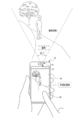
- the smart device 10 has an imaging operation (hereinafter, also simply referred to as “imaging operation”) for imaging an imaging region defined by an angle of view ⁇ 1 and a laser beam for irradiating the imaging region. Then, a distance measuring operation (hereinafter, also simply referred to as “distance measuring operation”) is performed in which distance measurement is performed by receiving the reflected light of the laser beam with respect to the imaging region.
- Imaging operation also simply referred to as “imaging operation”
- distance measuring operation is performed in which distance measurement is performed by receiving the reflected light of the laser beam with respect to the imaging region.
- Laser light is an example of "directional light” according to the technique of the present disclosure.
- distance measurement refers to a process of measuring the distance from the smart device 10 to the distance measurement target in the imaging region.
- range-finding target refers to an object that reflects laser light, and in the example shown in FIG. 1, a person and a tree are shown as distance-finding targets in the imaging region.
- the smart device 10 include a smartphone or a tablet terminal which is an electronic device having an imaging function.
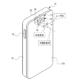
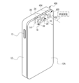
- the smart device 10 includes a housing 12.
- the distance measuring image pickup device 14 is housed in the housing 12.
- the distance measuring image pickup device 14 includes a light irradiator 16 and a light receiver 18.
- the light irradiator 16 includes an LD 24, and the light receiver 18 includes a photoelectric conversion element 26.
- the imaging operation and the ranging operation are performed by the ranging imaging device 14.
- the distance measuring image pickup device 14 is an example of the "imaging unit (imaging device)" and the distance measuring unit (distance measuring device) according to the technique of the present disclosure.
- An instruction key 13 is arranged on the side surface of the smart device 10.
- the instruction key 13 receives various instructions.
- the "various instructions" referred to here are, for example, an instruction to display a menu screen on which various menus can be selected, an instruction to select one or more menus, an instruction to confirm the selected contents, and an instruction to delete the selected contents. Refers to instructions, etc.
- Translucent windows 20 and 22 are provided in the upper left portion of the back surface 12A of the housing 12 when the smart device 10 is placed vertically (the upper left portion of the rear view of the smart device 10 in the vertically installed state). ..
- the translucent windows 20 and 22 are optical elements (for example, lenses) having translucency, are arranged along the horizontal direction at predetermined intervals (for example, at intervals of several millimeters), and are exposed from the back surface 12A.
- the light irradiator 16 irradiates the distance measurement target with the laser beam emitted from the LD 24 through the translucent window 20.
- laser light in the infrared wavelength region is adopted.
- the wavelength range of the laser light is not limited to this, and may be laser light in another wavelength range.
- the receiver 18 takes in IR reflected light through the translucent window 22.
- the IR reflected light refers to the reflected light by the laser light emitted to the distance measuring target by the light irradiator 16. Further, the receiver 18 takes in the visible reflected light through the translucent window 22.
- the visible reflected light refers to the reflected light by the visible light (for example, the visible light contained in sunlight) irradiated to the imaging region. In the following, for convenience of explanation, when it is not necessary to distinguish between IR reflected light and visible reflected light, they are simply referred to as “reflected light”.
- the light receiver 18 includes a photoelectric conversion element 26, and the photoelectric conversion element 26 receives the reflected light taken into the light receiver 18 through the translucent window 22 and receives electricity according to the amount of the received reflected light. Output a signal.
- the photoelectric conversion element 26 has a plurality of photodiodes arranged in a matrix.
- An example of the plurality of photodiodes is a photodiode for "4896 x 3265" pixels.
- a color filter is arranged on each photodiode included in the photoelectric conversion element 26.
- the color filters include a G filter corresponding to the G (green) wavelength region, an R filter corresponding to the R (red) wavelength region, a B filter corresponding to the B (blue) wavelength region, and a B filter corresponding to the B (blue) wavelength region, which contributes most to obtaining a brightness signal.
- the G filter, the R filter, and the B filter also have a function as an infrared light cut filter that cuts infrared light. Further, in the following, for convenience of explanation, when it is not necessary to distinguish between the G filter, the R filter, and the B filter, they are also referred to as “visible light filter”.
- the photoelectric conversion element 26 has R pixels, G pixels, B pixels, and IR pixels.
- the R pixel is a pixel corresponding to the photodiode in which the R filter is arranged
- the G pixel is the pixel corresponding to the photodiode in which the G filter is arranged
- the B pixel is the photodiode in which the B filter is arranged.
- the IR pixel is a pixel corresponding to the photodiode in which the IR filter is arranged.
- the R pixel, G pixel, B pixel, and IR pixel are arranged in each of the row direction (horizontal direction) and the column direction (vertical direction) with a predetermined periodicity.
- the arrangement of the R pixel, the G pixel, the B pixel, and the IR pixel is an arrangement obtained by replacing some G pixels with IR pixels in the X-Trans (registered trademark) arrangement. is there.
- the IR pixels are arranged with a specific periodicity along the row direction and the column direction.
- G pixel, B pixel, and IR pixel an array based on the X-Trans array is exemplified, but the technique of the present disclosure is not limited to this, and the R pixel is not limited thereto.
- G pixel, B pixel, and IR pixel may be an arrangement based on another arrangement such as a bayer arrangement or a honeycomb (registered trademark) arrangement.
- each color filter corresponding to each of R pixel, G pixel, and B pixel (hereinafter, these are also referred to as "visible light pixel") is set as a color filter that also transmits infrared light, and one color filter is used.
- a pair of photodiodes of a photodiode for visible light pixels and a photodiode for IR pixels (for example, InGaAs APD) may be arranged.
- the photoelectric conversion element 26 is divided into two regions. That is, the photoelectric conversion element 26 has a visible light image division region 26N1 and a distance measurement division region 26N2.
- the visible light image division region 26N1 is a group of visible light pixels composed of a plurality of visible light pixels, and is used for generating a visible light image.
- the distance measuring division area 26N2 is an IR pixel group consisting of a plurality of IR pixels and is used for distance measuring.
- the visible light image division region 26N1 receives visible reflected light and outputs an electric signal according to the amount of received light.
- the distance measuring division region 26N2 receives IR reflected light and outputs an electric signal according to the amount of received light.
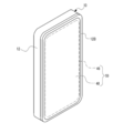
- a touch panel display 59 is provided on the front surface 12B of the housing 12.
- the touch panel display 59 includes a display 46 and a touch panel 48.
- An example of the display 46 is an organic EL display.
- the display 46 is not an organic EL display, but may be another type of display such as a liquid crystal display or an inorganic EL display.
- the display 46 is an example of a “display unit” according to the technique of the present disclosure.
- the touch panel 48 is an example of a "reception unit (reception device (acceptor))" according to the technology of the present disclosure.
- the display 46 displays images (for example, live view images and reproduced images), character information, and the like.
- the touch panel 48 is a transmissive touch panel and is superimposed on the surface of the display area of the display 46.
- the touch panel 48 receives an instruction from the user by detecting contact with an indicator such as a finger or a stylus pen.
- an out-cell type touch panel display in which the touch panel 48 is superimposed on the surface of the display area of the display 46 is mentioned, but this is only an example.
- an on-cell type or in-cell type touch panel display can be applied.
- the imaging region is imaged by the receiver 18. That is, the receiver 18 receives the visible light reflected light and generates a visible light image showing the imaging region as an image corresponding to the received visible light reflected light.
- the visible light image is an example of the "imaging area image" according to the technique of the present disclosure.
- the visible light image is displayed on the display 46 as a live view image or a still image according to the instruction received by the touch panel 48.
- the imaging region is defined by the angle of view ⁇ 1.
- the angle of view ⁇ 1 is changed according to the instruction received by the touch panel 48.
- the smart device 10 when an instruction to start distance measurement (hereinafter, also referred to as “distance measurement start instruction”) is received by the touch panel 48, a laser beam is irradiated by the light irradiator 16. To.
- the angle at which the laser beam is irradiated (hereinafter, also referred to as “irradiation angle”) is ⁇ 2, and the irradiation angle ⁇ 2 is changed according to the instruction received by the touch panel 48.
- the visible light image is displayed as a live view image on the display 46, and the distance measurement is started in response to the distance measurement start instruction received by the touch panel 48.
- the techniques of the present disclosure are not limited to this.
- the distance measurement may be started when the touch panel 48 receives the distance measurement start instruction while the visible light image is not displayed on the display 46.
- the distance measurement is performed for each IR pixel by receiving the IR reflected light by each of the plurality of IR pixels included in the distance measurement division area 26N2. Then, the distance measurement result for each IR pixel is displayed on the display 46 as a distance image.
- the distance image refers to an image in which the distance to the distance measurement target measured for each IR pixel is expressed by color and / or shading.
- the distance measurement result is displayed on the display 46 as a distance image or a distance superimposed image according to the instruction received by the touch panel 48.
- the distance superimposed image in which the distance superimposed image is displayed on the display 46 is a numerical value indicating the distance measurement result (in the example shown in FIG. 8) with respect to the visible light image (for example, the live view image). , 1.6m, 1.8m, and 5.3m).
- the distances from the smart device 10 to each of a plurality of typical locations (three locations in the example shown in FIG. 8) in the imaging region are displayed on the display 46 in a visible light image. ..
- a plurality of specific subjects in the imaging region for example, a subject included in the center region of the screen and / or a human being
- a contrast difference is equal to or greater than a default value. The part of is mentioned.
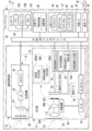
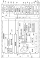
- the smart device 10 in addition to the light irradiator 16 and the receiver 18, the smart device 10 includes a controller 15, an input / output interface 40, an image memory 42, a UI device 44, an external I / F 52, and communication. It is equipped with an I / F 54.
- the controller 15 is an example of a "processing device” and a "computer” according to the technology of the present disclosure.
- the controller 15 includes a CPU 15A, a storage 15B, and a memory 15C.
- the CPU 15A is an example of a "processor", a “recognition processor” and a “specific processor” according to the technology of the present disclosure
- the memory 15C is an example of a "memory” according to the technology of the present disclosure.
- the CPU 15A, the storage 15B, and the memory 15C are connected via the bus 50, and the bus 50 is connected to the input / output interface 40. In the example shown in FIG. 9, one bus is shown as the bus 50 for convenience of illustration, but a plurality of buses may be used.
- the bus 50 may be a serial bus or a parallel bus including a data bus, an address bus, a control bus, and the like.
- the storage 15B stores various parameters and various programs.
- the storage 15B is a non-volatile storage device.
- a flash memory is adopted as an example of the storage 15B.
- the flash memory is merely an example, and examples of the storage 15B include various non-volatile memories such as a magnetoresistive memory and / or a ferroelectric memory instead of the flash memory or in combination with the flash memory. ..
- the non-volatile storage device may be EEPROM, HDD, and / or SSD or the like.
- the memory 15C temporarily stores various information and is used as a work memory.
- An example of the memory 15C is RAM, but the memory is not limited to this, and other types of storage devices may be used.
- the CPU 15A reads a necessary program from the storage 15B and executes the read program on the memory 15C.
- the CPU 15A controls the entire smart device 10 according to a program executed on the memory 15C.
- a plurality of devices are connected to the input / output interface 40, and the input / output interface 40 controls the exchange of various information between the plurality of devices.
- a controller 15 As a plurality of devices connected to the input / output interface 40, a controller 15, a light irradiator 16, a receiver 18, an image memory 42, a UI device 44, an external I / F 52, and a communication I / F54 is shown.
- the external I / F 52 controls the exchange of various information with and from a device existing outside the smart device 10 (hereinafter, also referred to as an "external device").
- An example of the external I / F 52 is a USB interface.
- External devices such as smart devices, personal computers, servers, USB memory sticks, memory cards, and / or printers can be directly or indirectly connected to the USB interface.
- the communication I / F54 has communication functions such as LTE, 5G, wireless LAN, and / or Bluetooth (registered trademark), and controls the exchange of various information between the external device and the CPU 15A.
- the communication I / F 54 is communicably connected to the network 56 (for example, the Internet) via a base station (not shown), and various information is exchanged between the external device on the network 56 and the CPU 15A. Controls.
- the UI device 44 includes a display 46, and the CPU 15A causes the display 46 to display various information. Further, the UI device 44 includes a reception device 47.
- the reception device 47 includes a touch panel 48 and a hard key unit 53.
- the hard key unit 53 is at least one hard key including the instruction key 13 (see FIG. 2).
- the CPU 15A operates according to various instructions received by the touch panel 48.
- the hard key unit 53 is included in the UI device 44 here, the technique of the present disclosure is not limited to this, and for example, the hard key unit 53 may be connected to the external I / F 52. Good.
- the light irradiator 16 includes a transparent window 20, a beam expander 21, a collimating lens 23, an LD24, and an LD driver 25, and is transparent from the imaging region side (object side) to the LD24 along the optical axis L1.
- the light window 20, the beam expander 21, and the collimating lens 23 are arranged in this order.
- the LD driver 25 is connected to the LD 24 and the input / output interface 40, and drives the LD 24 according to the instruction of the CPU 15A to emit laser light from the LD 24.
- the laser light emitted from the LD 24 is converted into parallel light by the collimated lens 23, then the light diameter is expanded by the beam expander 21, and the laser light is emitted from the translucent window 20 toward the distance measurement target.
- the light receiver 18 includes a translucent window 22, an objective lens 30A, a focus lens 30B, an aperture 30C, a photoelectric conversion element 26, a photoelectric conversion element driver 32, and a signal processing circuit 34.
- the translucent window 22, the objective lens 30A, the focus lens 30B, and the aperture 30C are arranged in this order from the imaging region side (object side) to the photoelectric conversion element 26 along the optical axis L2.
- the photoelectric conversion element driver 32 is connected to the photoelectric conversion element 26 and the input / output interface 40, and drives the photoelectric conversion element 26 according to the instructions of the CPU 15A.
- the photoelectric conversion element driver 32 supplies the photoelectric conversion element 26 with an imaging timing signal that defines the timing of imaging performed by the photoelectric conversion element 26 under the control of the CPU 15A.
- the photoelectric conversion element 26 resets, exposes, and outputs an electric signal according to the imaging timing signal supplied from the photoelectric conversion element driver 32.
- Examples of the imaging timing signal include a vertical synchronization signal and a horizontal synchronization signal.
- the receiver 18 includes a focusing control mechanism 31.
- the focusing control mechanism 31 includes a focus lens 30B, a moving mechanism 60, a motor 62, and a motor driver 64.
- the focus lens 30B is slidably supported along the optical axis L2 by the moving mechanism 60.
- the motor 62 is connected to the moving mechanism 60 and the motor driver 64.
- the motor driver 64 is connected to the input / output interface 40 and drives the motor 62 according to an instruction from the CPU 15A.
- the moving mechanism 60 is connected to a drive shaft (not shown) of the motor 62, and receives power from the motor 62 to selectively move the focus lens 30B between the object side and the image side along the optical axis L2. Let me.
- the CPU 15A adjusts the focusing position by controlling the drive of the motor 62 via the motor driver 64.
- the "focus position" is the light of the focus lens 30B in a state of being in focus (for example, a state in which the contrast of the visible light image is maximized or a state in which a predetermined subject depth is achieved). Refers to the position on the axis L2.
- the control for aligning the focus lens 30B with the focusing position is also referred to as “focusing control”.
- the diaphragm 30C is a fixed diaphragm whose opening does not change. In the case of a fixed aperture, the exposure adjustment is performed by the electronic shutter of the photoelectric conversion element 26.
- the diaphragm 30C may be a variable diaphragm instead of a fixed diaphragm.
- the objective lens 30A, the focus lens 30B, and the diaphragm 30C included in the light receiver 18 are merely examples, and the technique of the present disclosure is established even if the configuration of the lens and / or the position of the diaphragm 30C is changed.
- Reflected light is incident on the receiver 18 from the translucent window 22.
- the reflected light incident on the translucent window 22 is imaged on the photoelectric conversion element 26 via the objective lens 30A, the focus lens 30B, and the diaphragm 30C.
- the photoelectric conversion element 26 is connected to the signal processing circuit 34, and outputs pixel data indicating a pixel value to the signal processing circuit 34 for each pixel of the visible light pixel and the IR pixel.
- the signal processing circuit 34 digitizes the pixel data by performing A / D conversion on the pixel data input from the photoelectric conversion element 26, and performs various signal processing on the digitized pixel data.
- the signal processing circuit 34 includes a visible light pixel data processing circuit 34A and a distance image generation circuit 34B.
- the visible light pixel data processing circuit 34A performs visible light by performing known signal processing such as white balance adjustment, sharpness adjustment, gamma correction, color space conversion processing, and color difference correction on the pixel data of the visible light pixel. Generate an image. Then, the visible light pixel data processing circuit 34A stores the visible light image in the image memory 42. The visible light image in the image memory 42 is updated by overwriting and saving one frame of the visible light image in the image memory 42.
- the distance measuring image pickup device 14 includes a TOF camera 19.
- the TOF camera 19 includes a light irradiator 16, a distance measuring division area 26N2, and a distance image generation circuit 34B.
- the distance image generation circuit 34B acquires an emission timing signal indicating the timing at which the laser beam is emitted from the LD 24 (hereinafter, also referred to as “emission timing”) from the CPU 15A.
- the distance image generation circuit 34B is smart for each IR pixel based on the emission timing indicated by the emission timing signal and the timing at which the IR reflected light is received by each IR pixel (hereinafter, also referred to as “light receiving timing”). The distance from the device 10 to the distance measurement target is measured.
- the distance image generation circuit 34B generates a distance image based on the measurement result for each IR pixel, and stores the generated distance image in the image memory 42.
- the distance image in the image memory 42 is updated by overwriting and saving the distance image for one frame in the image memory 42.
- the storage 15B includes an image pickup processing program 70, a distance measurement processing program 72, a parallel processing program 74, a change processing program 76, a display control processing program 78, an image recognition dictionary 80, and irradiation energy.
- Table 82 is stored.
- “distance measurement imaging” is described below. It is called a "processing program”.
- the IR reflected light is received by the IR pixels, and the distance from the smart device 10 to the distance measurement target is measured based on the emission timing and the reception timing.
- the IR reflected light is completely cut by the visible light filter, but it is difficult to completely cut the IR reflected light by the visible light filter depending on the intensity of the IR reflected light.
- the IR reflected light may appear as noise in the visible light image and affect the image quality of the visible light image.
- the distance to the subject is a predetermined distance (for example, 0.5 m) or less
- the period during which the imaging operation is performed for example, the photoelectric conversion element 26
- the distance measurement result is used for focusing control
- the distance measurement result is reflected in the focusing control while the distance measurement operation is stopped. Therefore, there is a concern that the accuracy of focusing control will be lower than in the case where the distance measurement operation is always performed.
- focusing control may be performed according to a distance measurement result that does not match the current situation.
- the distance to the subject is a predetermined distance, depending on the reflectance of the subject, the IR reflected light may not appear as noise in the visible light image. However, if the distance to the subject is less than the predetermined distance, the distance measuring operation will stop.
- the CPU 15A reads the distance measuring image processing program from the storage 15B and executes the distance measuring image processing according to the read distance measuring image processing program.
- the ranging imaging processing includes an imaging process described later (see FIG. 18), a distance measuring process described later (see FIG. 19), a parallel process described later (see FIG. 17), a change process described later (see FIG. 20), and a modification process described later. This is a process including a display control process (see FIGS. 21A and 21B).
- the CPU 15A reads out the image pickup processing program 70 from the storage 15B, and executes the image pickup process (see FIG. 18) according to the read out image pickup process program 70. Further, the CPU 15A reads the distance measurement processing program 72 from the storage 15B, and executes the distance measurement processing (see FIG. 19) according to the read distance measurement processing program 72. Further, the CPU 15A reads the parallel processing program 74 from the storage 15B, and executes parallel processing (see FIG. 17) according to the read parallel processing program 74. Further, the CPU 15A reads the change processing program 76 from the storage 15B, and executes the change process (see FIG. 20) according to the read change process program 76. Further, the CPU 15A reads out the display control processing program 78 from the storage 15B, and executes the display control processing (see FIGS. 21A and 21B) according to the read display control processing program 78.
- the distance measurement imaging process is realized by the CPU 15A operating as a control unit 90, a recognition unit 92, an acquisition unit 94, a determination unit 96, and a change unit 98.
- the control unit 90 executes parallel processing. That is, the control unit 90 controls the distance measuring image pickup device 14 to perform the imaging operation and the distance measuring operation in parallel.
- the imaging operation and the distance measuring operation are performed in parallel.
- this is only an example, and the imaging operation and the distance measuring operation are not performed in parallel.
- the technique of the present disclosure is established. For example, the technique of the present disclosure is established even if a part of the period in which the imaging operation is performed and the period in which the distance measuring operation is performed overlap.
- control unit 90 acquires a visible light image and a distance image from the image memory 42, and displays the acquired visible light image and an image based on the distance image on the display 46. Specifically, the visible light image, the distance image, and the distance superimposed image are displayed on the display 46 in a switchable manner under the control of the control unit 90.
- the recognition unit 92 acquires a visible light image from the image memory 42, and performs image recognition on the acquired visible light image.
- the recognition unit 92 acquires the image recognition dictionary 80 from the storage 15B, and recognizes the image included in the visible light image by referring to the acquired image recognition dictionary 80.
- the image recognition dictionary 80 is information in which a plurality of types of high-reflectance object images and an identifier capable of identifying each of the plurality of types of high-reflectance object images (hereinafter, also simply referred to as “identifier”) are associated with each other. is there.
- the high reflectance object image refers to an image showing an object having a reflectance equal to or higher than the reference reflectance (hereinafter, also referred to as a “high reflectance object”).
- the reference reflectance is, for example, a sensory test and / or a reflectance as a reflectance that appears as noise in a visible light image when IR reflected light from a laser beam irradiating an object passes through a visible light filter and reaches a visible light pixel.
- the reflectance derived in advance by computer simulation or the like can be mentioned.
- Examples of the object having the reference reflectance or higher include a predetermined object as a glossy object, a predetermined object as a white object, and the like.
- the predetermined object as a glossy object refers to, for example, a mirror plate, a glossy sphere, or the like.
- the predetermined object as a white object refers to, for example, a white coat, a white balloon, white hair, or the like.
- the mirror plate is an example of a "mirror-shaped object" according to the technique of the present disclosure.
- the image recognition dictionary 80 is information based on the learning result obtained by machine learning the correspondence between the image and the subject recognition result.
- the image recognition dictionary 80 is information based on the learning result obtained by machine learning the correspondence between the image and the subject recognition result.
- a form example in which information based on the learning result obtained by machine learning is used as the image recognition dictionary 80 is given, but this form example is only an example, and the sensory test and / Alternatively, the information derived in advance by computer simulation or the like may be used as the image recognition dictionary 80.
- the acquisition unit 94 acquires reflectance information that can specify the reflectance in the imaging region.
- the image recognition result is acquired by the acquisition unit 94 as the reflectance information.
- the image recognition result refers to a result obtained by performing image recognition on a visible light image by the recognition unit 92. Specifically, when the high-reflectance object image is recognized by the recognition unit 92, the image recognition result includes an identifier that can identify the recognized high-reflectance object image, and the high-reflectance object image is included by the recognition unit 92. If is not recognized, the image recognition result includes information indicating that the high reflectance object image was not recognized.
- the "image recognition result” is an example of "reflectance information” and "information based on the image in the imaging region" according to the technique of the present disclosure.
- the determination unit 96 determines whether or not a high-reflectance object image is included in the visible light image with reference to the image recognition result acquired by the acquisition unit 94.
- the change unit 98 is in a state where the imaging operation and the ranging operation are performed by the ranging imaging device 14.
- the irradiation energy of the laser beam (hereinafter, also simply referred to as “irradiation energy”) is changed according to the image recognition result acquired by the acquisition unit 94.
- the changing unit 98 acquires the irradiation energy table 82 from the storage 15B, and changes the intensity of the laser light emitted from the LD 24 via the LD driver 25 according to the acquired irradiation energy table 82. Change the irradiation energy. That is, under the state where the imaging operation and the distance measuring operation are performed in parallel by the parallel processing executed by the control unit 90, the LD driver 25 emits the laser beam of the intensity changed by the changing unit 98. It is emitted from the LD24.
- the intensity information refers to information indicating the intensity of the laser beam emitted to the LD24.
- the intensity of the laser beam indicated by the intensity information is weaker than the reference intensity.
- the reference intensity is an example of the "first to fourth reference irradiation energies" according to the technique of the present disclosure.
- the reference intensity refers to, for example, the intensity set as a default value as the intensity of the laser beam emitted to the LD24.
- the intensity set as the default value is, for example, the IR reflected light from the laser beam radiated to the reference subject (for example, the face of a person predetermined as the face of a general person) can be measured by the IR pixel.
- the intensity of the laser beam received with a large amount of light refers to the intensity derived in advance by a sensory test and / or a computer simulation or the like.
- the intensity information is defined so that the higher the reflectance of the high-reflectance object indicated by the high-reflectance object image specified by the identifier, the weaker the intensity of the laser beam.
- a mirror plate, a glossy sphere, and a white coat are shown as high-reflectance object images specified by identifiers.
- Intensity information indicating the intensity X 11 is associated with the mirror plate.
- Intensity information indicating the intensity X 12 is associated with the glossy sphere.
- the strength information indicating the strength X 13 is associated with the white coat.
- the magnitude relationship of "strength X 11 ⁇ strength X 12 ⁇ strength X 13 " is established between the strength X 11 , the strength X 12 , and the strength X 13.
- the control unit 90 When switching the visible light image, the distance image, and the distance superimposition image displayed on the display 46 under the control of the control unit 90, the control unit 90 receives an instruction received by the touch panel 48 as shown in FIG. 13 as an example. Therefore, the display mode selection screen 100 is displayed on the display 46.
- the display mode selection screen 100 is a screen used by the user or the like when the user or the like is made to select any of the visible light image display mode, the distance image display mode, and the distance superimposition image display mode.
- the visible light image display mode is an operation mode in which the control unit 90 displays a visible light image on the display 46.
- the distance image display mode is an operation mode in which the control unit 90 displays a distance image on the display 46.
- the distance superimposition image display mode is an operation mode in which the control unit 90 displays the distance superimposition image on the display 46.
- Softkeys 100A, 100B, and 100C are displayed on the display mode selection screen 100.
- the soft key 100A is turned on by the user or the like via the touch panel 48 when the user or the like selects the visible light image display mode.
- the softkey 100B is turned on by the user or the like via the touch panel 48 when the user or the like selects the distance image display mode.
- the softkey 100C is turned on by the user or the like via the touch panel 48 when the user or the like selects the distance superimposition image display mode.
- display mode when the visible light image display mode, the distance image display mode, and the distance superimposition image display mode are described without distinction, they are referred to as "display mode".
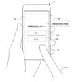
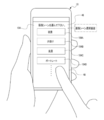
- the control unit 90 causes the display 46 to display the ranging range designation guide screen 102 as shown in FIG. 14 as an example.
- the ranging range designation guidance screen 102 is a screen that guides the user or the like to specify the ranging range.
- a message asking the user whether or not to specify the ranging range (hereinafter, also referred to as “guidance message”) is displayed.
- the message "Do you want to specify the ranging range?") is shown as an example of the guidance message.
- soft keys 102A and 102B are displayed on the distance measuring range designation guidance screen 102.
- the softkey 102A is turned on by the user or the like via the touch panel 48 when the user or the like specifies a ranging range.
- the softkey 102B is turned on by the user or the like via the touch panel 48 when the user or the like does not specify the ranging range, that is, when the entire imaging area is set as the ranging range.
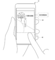
- the control unit 90 displays as shown in FIG. 15 as an example.
- a visible light image is displayed as a live view image on the 46. While the live view image is displayed on the display 46, an image area (in the example shown in FIG. 15, a rectangular area surrounded by a broken line on the visible light image) is designated by a user or the like via the touch panel 48.
- the real space area corresponding to the image area designated by the user or the like (hereinafter, also referred to as “designated image area”) is designated as the distance measurement target by the distance measurement imaging device 14.
- the touch panel 48 outputs the area position identification information (for example, coordinates) capable of specifying the position of the designated image area on the visible light image to the control unit 90.
- the control unit 90 outputs the division area position information (for example, pixel address) capable of specifying the position of the distance measurement designated division area 26N2a in the distance measurement division area 26N2 to the photoelectric conversion element driver 32.
- the distance measurement designated division area 26N2a refers to a division area of the distance measurement division area 26N2 at a position corresponding to the position of the designated image area specified by the area position identification information input from the touch panel 48. ..
- the photoelectric conversion element driver 32 drives only the distance measurement designated division area 26N2a of the distance measurement division areas 26N2 in the distance measurement operation, so that the distance measurement image pickup device 14 is subjected to the distance measurement designated division area 26N2.
- Distance measurement is performed using the IR reflected light received only by 26N2a. That is, the distance measurement is performed using the IR reflected light received by only at least one IR pixel included in the designated region among the plurality of IR pixels included in the TOF camera 19 (see FIG. 9). ..
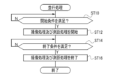
- step ST10 the control unit 90 determines whether or not the condition for starting the parallel processing (hereinafter, also referred to as “parallel processing start condition”) is satisfied.
- the parallel processing start condition there is a condition that the touch panel 48 is instructed to start the parallel processing. If the parallel processing start condition is not satisfied in step ST10, the determination is denied and the determination in step ST10 is performed again. If the parallel processing start condition is satisfied in step ST10, the determination is affirmed and the parallel processing shifts to step ST12.
- step ST12 the control unit 90 starts the imaging operation and the ranging operation for the ranging imaging device 14 by starting the imaging process and the ranging process, and then the parallel processing shifts to step STR14.
- step ST14 the control unit 90 determines whether or not the condition for terminating the parallel processing (hereinafter, also referred to as "parallel processing end condition") is satisfied.
- the parallel processing end condition there is a condition that the touch panel 48 has received an instruction to end the parallel processing. If the parallel processing end condition is not satisfied in step ST14, the determination is denied and the determination in step ST14 is performed again. If the parallel processing end condition is satisfied in step ST14, the determination is affirmed, and the parallel processing shifts to step ST16.
- step ST16 the control unit 90 ends the imaging operation and the ranging operation for the ranging imaging device 14 by ending the imaging process and the ranging process, and then the parallel processing ends.
- step ST20 the control unit 90 determines whether or not the timing for causing the ranging imaging device 14 to perform imaging (hereinafter, also referred to as “imaging timing”) has arrived. To do.
- imaging timing there is a timing determined by a cycle that defines the frame rate. For example, if the frame rate is 120 fps, the period for defining the frame rate is 1/120 second. If the imaging timing has not arrived in step ST20, the determination is denied and the imaging process proceeds to step ST28. When the imaging timing arrives in step ST20, the determination is affirmed, and the imaging process shifts to step ST22.
- step ST22 the control unit 90 resets the photoelectric conversion element 26 by causing the photoelectric conversion element driver 32 to output an imaging timing signal, exposes the photoelectric conversion element 26, and then performs imaging processing. Moves to step ST24.
- step ST24 the control unit 90 causes the visible light pixel data processing circuit 34A to perform various signal processing. That is, the visible light pixel data processing circuit 34A generates a visible light image by performing various signal processing on the pixel data of the visible light pixels included in the photoelectric conversion element 26.
- step ST26 the control unit 90 stores the visible light image in the image memory 42 in the visible light pixel data processing circuit 34A, and then the imaging process shifts to step ST28.
- step ST28 the control unit 90 determines whether or not the condition for ending the imaging process (hereinafter, also referred to as "imaging process end condition") is satisfied.
- the imaging process end condition there is a condition that the process of step ST16 shown in FIG. 17 is executed. If the condition for ending the imaging process is not satisfied in step ST28, the determination is denied and the imaging process proceeds to step ST20. If the condition for ending the imaging process is satisfied in step ST28, the determination is affirmed and the imaging process ends.
- step ST40 whether or not the timing at which the control unit 90 causes the distance measuring imaging device 14 to perform distance measuring (hereinafter, also referred to as “distance measuring timing”) has arrived. Is determined.
- the distance measurement timing is, for example, a timing that arrives at a cycle shorter than the imaging timing. If the distance measurement timing has not arrived in step ST40, the determination is denied and the distance measurement process proceeds to step ST56. When the distance measurement timing arrives in step ST40, the determination is affirmed, and the distance measurement process shifts to step ST42.
- step ST42 the control unit 90 irradiates the light irradiator 16 with a laser beam. That is, the control unit 90 emits laser light to the LD 24 by controlling the LD driver 25, and then the distance measuring process shifts to step ST44.
- step ST44 the control unit 90 determines whether or not the IR reflected light is received by the distance measurement designated division area 26N2a. In step ST44, if the IR reflected light is not received by the distance measuring designated division region 26N2a, the determination is denied and the determination in step ST44 is performed again. In step ST44, when the IR reflected light is received by the distance measuring designated division area 26N2a, the determination is affirmed and the distance measuring process proceeds to step ST46.
- step ST46 the control unit 90 causes the distance image generation circuit 34B to generate a distance image based on the distance measurement result, and then the distance measurement process shifts to step ST48.
- step ST48 the control unit 90 stores the distance image generated in step ST46 in the image memory 42 in the distance image generation circuit 34B, and then the distance measurement process shifts to step ST50.
- the distance measuring operation performed by the ranging imaging device 14 is a focusing operation for focusing, and the ranging imaging device 14 is obtained by performing the ranging by the ranging operation for focusing. Focusing on the imaging area is performed based on the distance measurement result. Therefore, in the distance measuring process, the processes of steps ST50 to ST54 are executed by the control unit 90.
- step ST50 the control unit 90 acquires a distance image from the image memory 42, derives the distance from the smart device 10 to a specific area in the imaging area based on the acquired distance image, and then performs the distance measurement process.
- the process proceeds to step ST52.
- the specific area refers to, for example, an area designated by a user or the like via the touch panel 48 as an area on the object side to be focused.
- the specific area is not limited to this, and may be, for example, the face of a person specified by activating the so-called face detection function, or one of a plurality of typical locations (see FIG. 8). It may be one place.
- step ST52 the control unit 90 derives the focusing position based on the distance derived in step ST50, and then the distance measuring process shifts to step ST54.
- the in-focus position is, for example, an in-focus position derivation table in which the distance and the in-focus position are associated (not shown), or an in-focus position derivation calculation formula in which the distance is an independent variable and the in-focus position is a dependent variable. It is derived from (not shown) by the control unit 90.
- step ST54 the control unit 90 operates the focusing control mechanism 31 to move the focus lens 30B to the focusing position derived in step ST52, and then the ranging process shifts to step ST56.
- step ST56 the control unit 90 determines whether or not the condition for ending the distance measurement process (hereinafter, also referred to as "distance measurement end condition") is satisfied.
- the distance measurement processing end condition there is a condition that the processing of step ST16 shown in FIG. 17 is executed. If the condition for ending the distance measurement process is not satisfied in step ST56, the determination is denied and the distance measurement process proceeds to step ST40. If the distance measurement processing end condition is satisfied in step ST56, the determination is affirmed and the distance measurement process ends.
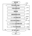
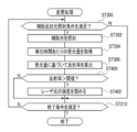
- step ST70 the recognition unit 92 determines whether or not the visible light image in the image memory 42 has been updated. If the visible light image in the image memory 42 has not been updated in step ST70, the determination is denied and the change process proceeds to step ST82. When the visible light image in the image memory 42 is updated in step ST70, the determination is affirmed, and the change process shifts to step ST71.
- step ST71 the recognition unit 92 acquires a visible light image from the image memory 42, and then the change process shifts to step ST72.
- step ST72 the recognition unit 92 executes image recognition with reference to the image recognition dictionary 80 for the visible light image acquired in step ST70, and then the change process shifts to step ST74.
- step ST74 the acquisition unit 94 acquires the image recognition result obtained by executing image recognition by the recognition unit 92 in step ST72, and then the change process shifts to step ST76.
- step ST76 the determination unit 96 determines whether or not the visible light image acquired in step ST70 includes a high reflectance object image based on the image recognition result acquired in step ST74. In step ST76, if the visible light image acquired in step ST70 does not include the high reflectance object image, the determination is denied and the change process proceeds to step ST82. In step ST76, if the visible light image acquired in step ST70 includes a high-reflectance object image, the determination is affirmed and the change process proceeds to step ST78.
- step ST78 the change unit 98 acquires the intensity information corresponding to the identifier included in the image recognition result acquired in step ST74 from the irradiation energy table 82, and then the change process shifts to step ST80.
- step ST80 the change unit 98 changes the intensity of the laser beam emitted from the LD 24 via the LD driver 25 to the intensity indicated by the intensity information acquired in step ST78, and then the change process shifts to step ST82. To do.
- step ST82 the control unit 90 determines whether or not the condition for terminating the change process (hereinafter, also referred to as "change process end condition") is satisfied.
- the change processing end condition there is a condition that the processing of step ST16 shown in FIG. 17 is executed. If the change processing end condition is not satisfied in step ST82, the determination is denied and the change processing proceeds to step ST70. If the change processing end condition is satisfied in step ST82, the determination is affirmed and the change processing ends.
- step ST100 the control unit 90 determines whether or not the visible light image display mode is set.
- the determination is affirmed, and the display control process shifts to step ST102. If the visible light image display mode is not set in step ST100, the determination is denied and the display control process shifts to step ST106.
- step ST102 the control unit 90 acquires the latest visible light image from the image memory 42, and then the display control process shifts to step ST104.
- step ST104 the control unit 90 causes the display 46 to display the latest visible light image acquired in step ST102, and then the display control process shifts to step ST122.
- the live view image obtained by performing the live view image imaging operation of imaging the imaging region for the live view image by the distance measuring image pickup device 14 is processed in steps ST100 to ST104. By being repeatedly executed, it is displayed on the display 46.
- step ST106 the control unit 90 determines whether or not the distance image display mode is set. If the distance image display mode is set in step ST106, the determination is affirmed, and the display control process shifts to step ST108. If the distance image display mode is not set in step ST106, the determination is denied and the display control process shifts to step ST112 shown in FIG. 21B.
- step ST108 the control unit 90 acquires the latest distance image from the image memory 42, and then the display control process shifts to step ST110.
- step ST110 the control unit 90 causes the display 46 to display the latest distance image acquired in step 108, and then the display control process shifts to step ST122.
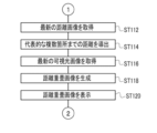
- step ST112 shown in FIG. 21B the control unit 90 acquires the latest distance image from the image memory 42, and then the display control process shifts to step ST114.
- step ST114 the control unit 90 derives the distances from the smart device 10 to a plurality of typical locations (see FIG. 8) based on the latest distance image acquired in step ST112, and then the display control process is performed. The process proceeds to step ST116.
- step ST116 the control unit 90 acquires the latest visible light image from the image memory 42, and then the display control process shifts to step ST118.
- step ST118 the control unit 90 generates a distance superimposition image by superimposing the distance derived in step ST114 on the latest visible light image acquired in step ST116, and then the display control process proceeds to step ST120. Transition.
- the position where the distance derived in step ST114 is superimposed on the latest visible light image acquired in step ST116 is a position corresponding to a plurality of typical locations.
- step ST120 the control unit 90 causes the display 46 to display the distance superimposed image generated in step ST118, and then the display control process shifts to step ST122 shown in FIG. 21A.
- step ST122 the control unit 90 determines whether or not the condition for terminating the display control process (hereinafter, also referred to as "display control process end condition") is satisfied.
- the display control process end condition there is a condition that the touch panel 48 has received an instruction to end the display control process. If the display control process end condition is not satisfied in step ST122, the determination is denied and the display control process shifts to step ST100. If the display control process end condition is satisfied in step ST122, the determination is affirmed and the display control process ends.
- the control unit 90 controls the distance measuring image pickup device 14 to perform an imaging operation and a distance measuring operation. Further, the reflectance information (“image recognition result” in the example shown in FIG. 12) capable of specifying the reflectance in the imaging region is acquired by the acquisition unit 94. Then, while the imaging operation and the distance measuring operation are being performed, the intensity of the laser beam is changed by the changing unit 98 according to the reflectance information acquired by the acquiring unit 94. Therefore, according to this configuration, it is possible to reduce the influence of the laser light on the visible light image as compared with the case where the intensity of the laser light is determined regardless of the reflectance in the imaging region.
- the intensity of the laser light is changed by the changing unit 98 according to the information based on the visible light image (“image recognition result” in the example shown in FIG. 12). Therefore, according to this configuration, the influence of the IR reflected light on the visible light image is reduced with high accuracy as compared with the case where the intensity of the laser light is changed only by the distance to the imaging region or only the shutter speed. can do.
- the intensity of the laser beam is changed by the changing unit 98 according to the image recognition result. Therefore, according to this configuration, the influence of the IR reflected light on the visible light image is reduced with high accuracy as compared with the case where the intensity of the laser light is changed only by the distance to the imaging region or only the shutter speed. can do.
- the image recognition result obtained by referring to the image recognition dictionary 80 by the recognition unit 92 and performing image recognition on the visible light image is acquired by the acquisition unit 94.
- the image recognition dictionary 80 is information based on the learning result obtained by machine learning the correspondence between the image and the subject recognition result. Therefore, according to this configuration, the IR reflection on the visible light image is compared with the case where it is determined whether or not the IR reflected light affects the visible light image only from the result of the user or the like visually recognizing the imaging region. The influence of light can be reduced with high accuracy.
- the intensity of the laser light is changed by the change unit 98 as a reference intensity. Is weakened than. Therefore, according to this configuration, the IR reflected light from the light-reflecting object is more than the case where the intensity of the laser light is always equal to or higher than the reference intensity regardless of whether or not a high-reflectance object is included in the imaging region. The influence on the visible light image can be reduced.
- the intensity of the laser light is changed by the change unit 98 as the reference intensity. Is weakened than. Therefore, according to this configuration, the IR reflected light from the light reflectance object is compared with the case where the intensity of the laser light is always equal to or higher than the reference intensity regardless of whether or not a glossy object is included in the imaging region. Can reduce the effect of on the visible light image.
- the intensity of the laser beam is changed when the image recognition result acquired by the acquisition unit 94 is an image recognition result indicating that a mirror-like object (for example, a mirror plate) is included. It is weakened by the part 98 below the reference strength. Therefore, according to this configuration, the IR reflected light from the light reflectance object is more than the case where the intensity of the laser light is always equal to or higher than the reference intensity regardless of whether or not a mirror-like object is included in the imaging region. The influence on the visible light image can be reduced.
- the distance measuring image pickup device 14 has a TOF camera 19. Therefore, according to this configuration, the distance measurement result can be output as a distance image.
- a distance image is displayed on the display 46. Therefore, according to this configuration, the user or the like can visually recognize the distance image.
- distance measurement is performed using the IR reflected light received only by the distance measurement designated division area 26N2a (see FIG. 16). Therefore, according to this configuration, the processing load required for distance measurement is reduced as compared with the case where distance measurement is performed using the IR reflected light received by all the IR pixels included in the distance measurement division area 26N2. be able to.
- the smart device 10 light is received only by the IR pixel at the position corresponding to the position of the designated image area (“designated image area” in the example shown in FIG. 15) from the screen in the state where the live view image is displayed.
- Distance measurement is performed using the IR reflected light. Therefore, according to this configuration, the distance measurement can be performed using the IR reflected light received only by the IR pixels intended by the user among all the IR pixels included in the distance measurement division region 26N2.
- the distance measuring image pickup device 14 performs a live view image imaging operation for capturing an imaging region for a live view image as an imaging operation. Therefore, according to this configuration, it is possible to reduce the influence of the laser beam on the live view image as compared with the case where the intensity of the laser beam is determined regardless of the reflectance in the imaging region.
- the distance measuring image pickup device 14 performs a distance measuring operation for focusing as a distance measuring operation. That is, the distance measurement result is used for focusing control. Therefore, according to this configuration, it is possible to focus on the distance measurement target with high accuracy as compared with the case where the distance measurement result is not used for focusing control.
- the smart device 10 distance measurement is performed using laser light as directional light, which is light having directivity. Therefore, according to this configuration, the distance to the distance measurement target existing at a long distance can be measured with high accuracy as compared with the case where the distance measurement is performed without using the directional light.
- the changing unit 98 derives the intensity information corresponding to the identifier included in the image recognition result from the irradiation energy table 82, and changes the intensity of the laser light according to the derived intensity information.
- the techniques of the present disclosure are not limited to this.
- the changing unit 98 derives the identifier included in the image recognition result and the intensity information corresponding to the imaging scene from the irradiation energy table 182, and determines the intensity of the laser light according to the derived intensity information. You may change it.
- the irradiation energy table 182 is information in which the imaging scene and the intensity information are associated with each identifier.
- a night view, a sunset, and the like are given as an example of the imaging scene.
- the intensity indicated by the intensity information corresponding to a specific imaging scene having an imaging scene reflectance equal to or higher than the reference reflectance described in the above embodiment is the intensity in the above embodiment.
- the strength is weaker than the standard strength described.
- the imaging scene reflectance refers to a predetermined reflectance as the reflectance of the laser beam irradiated to the imaging scene.
- the imaging scene reflectance is a reflectance previously determined by a sensory test and / or a computer simulation or the like.
- the touch panel 48 receives the imaging scene instruction information for instructing the imaging scene.
- the changing unit 98 derives the intensity information corresponding to the imaging scene instructed by the imaging scene instruction information received by the touch panel 48 and the identifier included in the image recognition result from the irradiation energy table 182. Then, the changing unit 98 changes the intensity of the laser beam according to the intensity information derived from the irradiation energy table 182.
- the image capture scene selection screen 104 is displayed on the display 46 under the control of the control unit 90.
- the imaging scene selection screen 104 is a screen used by the user or the like when instructing the user or the like to instruct any one of the plurality of imaging scenes.
- a message prompting the user or the like to select an imaging scene is displayed.
- a plurality of softkeys such as softkeys 104A, 104B, 104C, and 104D (hereinafter, also referred to as "softkeys in the imaging scene selection screen 104") are displayed.
- the softkey 104A is turned on by the user or the like via the touch panel 48 when the user or the like selects a night view scene as an imaging scene.
- the softkey 104B is turned on by the user or the like via the touch panel 48 when the user or the like selects a sunset scene as an imaging scene.
- the softkey 104C is turned on by the user or the like via the touch panel 48 when the user or the like selects a landscape scene as an imaging scene.
- the softkey 104D is turned on by the user or the like via the touch panel 48 when the user or the like selects a portrait scene as an imaging scene. In this way, when the soft key in the imaging scene selection screen 104 is turned on by the user or the like, the imaging scene instruction information is received by the touch panel 48.
- the change process shown in FIG. 24 is executed by the CPU 15A as an example.
- the change process shown in FIG. 24 includes the process of step ST178 instead of the process of step ST78, and the process of step ST77 between the process of step ST76 and the process of step ST178. The difference is that it has.
- step ST77 the change unit 98 acquires the imaging scene instruction information received by the touch panel 48, and then the change process shifts to step ST178.
- step ST178 the changing unit 98 acquires the identifier included in the image recognition result acquired in step ST74 and the intensity information corresponding to the imaging scene instruction information acquired in step ST77 from the irradiation energy table 182, and then acquires the intensity information corresponding to the imaging scene instruction information acquired in step ST77.
- the change process proceeds to step ST80.
- the intensity of the laser beam is changed by the changing unit 98 according to the imaging scene instruction information received by the touch panel 48 and the identifier included in the image recognition result. Therefore, according to this configuration, it is possible to reduce the influence of the IR reflected light on the visible light image as compared with the case where the intensity of the laser light is determined regardless of the imaging scene.
- the laser beam is emitted.
- the strength is weakened below the reference strength by the change portion 98. Therefore, according to this configuration, even though the designated imaging scene is a specific imaging scene having an imaging scene reflectance of the reference reflectance or higher, the intensity of the laser light is always specified as compared with the case where the intensity of the laser light is always equal to or higher than the reference intensity. It is possible to reduce the influence of the IR reflected light in the imaging scene on the visible light image.
- the intensity information corresponding to the imaging scene instruction information received by the touch panel 48 is acquired by the changing unit 98
- the technique of the present disclosure is limited to this. Not done.
- the imaging scene may be specified by image recognition of the visible light image by the recognition unit 92.
- the recognition unit 92 acquires a visible light image from the image memory 42 and performs image recognition on the acquired visible light image to perform imaging indicated by the visible light image. Identify the imaging scene for the area. Specifically, the recognition unit 92 identifies the imaging scene with reference to the image recognition dictionary 80.
- the image recognition dictionary 80 includes information in which an imaging scene image indicating an imaging scene and scene identification information capable of identifying an imaging scene indicated by the imaging scene image are associated with each other.
- the recognition unit 92 performs image recognition on the visible light image acquired from the image memory 42 with reference to the image recognition dictionary 80. That is, the recognition unit 92 identifies the captured scene image corresponding to the visible light image from the image recognition dictionary 80, and acquires the scene identification information corresponding to the specified captured scene image from the image recognition dictionary 80.
- the change unit 98 derives the intensity information corresponding to the imaging scene specified by the scene identification information acquired by the recognition unit 92 and the identifier included in the image recognition result from the irradiation energy table 182. Then, the changing unit 98 changes the intensity of the laser beam to the intensity indicated by the intensity information derived from the irradiation energy table 182.
- the recognition unit 92 is an example of the “specific unit” according to the technique of the present disclosure.
- the change process shown in FIG. 26 is executed by the CPU 15A as an example.
- the change process shown in FIG. 26 does not have the process of step ST77, has the process of step 275 between the process of step ST74 and the process of step ST76, and step 178.
- the difference is that the process of step 278 is performed instead of the process of.
- step ST275 the recognition unit 92 identifies the captured scene image corresponding to the visible light image from the image recognition dictionary 80, and acquires the scene identification information corresponding to the specified captured scene image from the image recognition dictionary 80.
- step ST278 the change unit 98 has an intensity corresponding to the identifier included in the image recognition result acquired in step ST74 and the imaging scene identified by the scene identification information acquired in step ST275 from the irradiation energy table 182. The information is acquired, and then the change process proceeds to step ST80.
- the intensity of the laser light is changed by the changing unit 98 according to the imaging scene specified by the recognition unit 92 and the identifier included in the image recognition result. Therefore, according to this configuration, it is possible to reduce the influence of the IR reflected light on the visible light image as compared with the case where the intensity of the laser light is determined regardless of the imaging scene.
- the imaging scene identified by the scene identification information acquired by the recognition unit 92 has an imaging scene reflectance equal to or higher than the reference reflectance.
- the intensity of the laser beam is weakened by the change unit 98 below the reference intensity. Therefore, according to this configuration, when the intensity of the laser light is always equal to or higher than the reference intensity even though the imaging scene specified by the recognition unit 92 is a specific imaging scene having an imaging scene reflectance equal to or higher than the reference reflectance. It is possible to reduce the influence of the IR reflected light in a specific imaging scene on the visible light image as compared with the above.
- auxiliary light for imaging for example, visible light used as a so-called red-eye prevention measure
- auxiliary reflected light the reflected light of the auxiliary light reflected by the distance measuring object
- the smart device 200 is used as an example.
- the smart device 200 is different from the smart device 10 described in the above embodiment in that it has a distance measuring imager 214 instead of the distance measuring imager 14 and a receiver 218 instead of the receiver 18.
- the range-finding image pickup device 214 is different from the range-finding image pickup device 14 in that it has an auxiliary light irradiator 213.
- the auxiliary light irradiator 213 includes an LED 202 and an LED driver 204.
- the LED driver 204 is connected to the LED 202 and the input / output interface 40.
- the LED driver 204 controls the LED 202 according to an instruction from the CPU 15A (for example, the control unit 90). Under the control of the CPU 15A, the LED driver 204 generates auxiliary light for the LED 202 to irradiate the auxiliary light toward the imaging region.
- the LED 202 is an example of a "light source" according to the technique of the present disclosure.
- the receiver 218 is different from the receiver 18 in that it has a photoelectric conversion element 226 instead of the photoelectric conversion element 26.
- the photoelectric conversion element 226 is different in that it has a distance measurement designated division area 26N2b instead of the distance measurement designated division area 26N2a (see FIG. 16).
- the distance measurement designated division area 26N2b is different from the distance measurement designated division area 26N2a in that G pixels are applied instead of IR pixels.
- the distance measuring designated division area 26N2b receives the auxiliary reflected light under the control of the control unit 90.
- the distance measurement designated division area 26N2b is an example of the "light receiving element" according to the technique of the present disclosure.
- the CPU 15A realizes the distance measurement image processing by operating as the control unit 90, the acquisition unit 94, and the change unit 98 according to the distance measurement image processing program.
- the signal processing circuit 34 includes an A / D converter 34C.
- the A / D converter 34C is connected to the distance measurement designated division area 26N2b, and digitizes the amount of auxiliary reflected light received by the distance measurement designated division area 26N2b.
- the acquisition unit 94 acquires the amount of received light digitized by the A / D converter 34C, and the amount of received light received by the designated division area 26N2b for distance measurement per unit time (hereinafter, “light received per unit time”). It is obtained by calculating (also called “quantity").
- the irradiation energy table 282 is stored in the storage 15B.
- the irradiation energy table 282 is different from the irradiation energy table 82 in that the unit time light receiving amount is applied instead of the identifier.
- the change unit 98 acquires the intensity information corresponding to the unit time received light amount acquired by the acquisition unit 94 from the irradiation energy table 282. Then, the changing unit 98 changes the intensity of the auxiliary light emitted from the LED 202 via the LED driver 204 to the intensity indicated by the intensity information acquired from the irradiation energy table 282.
- the change process shown in FIG. 29 is executed by the CPU 15A as an example.
- step ST200 the control unit 90 determines whether or not the condition for irradiating the LED 202 with the auxiliary light (hereinafter, also referred to as “auxiliary light irradiation condition”) is satisfied. ..
- auxiliary light irradiation condition for example, there is a condition that the timing of irradiating the auxiliary light has arrived as a measure to prevent red-eye. If the auxiliary light irradiation condition is not satisfied in step ST200, the determination is denied and the change process proceeds to step ST210. If the auxiliary light irradiation condition is satisfied in step ST200, the determination is affirmed, and the change process proceeds to step ST202.
- step ST202 the control unit 90 irradiates the LED 202 with auxiliary light, and then the change process shifts to step ST204.
- step ST204 the acquisition unit 94 acquires by calculating the amount of received light received by the designated division area 26N2b for distance measurement per unit time (hereinafter, also referred to as “unit time received amount”). After that, the change process proceeds to step ST206.
- the technique of the present disclosure is not limited to this, and can be obtained by, for example, finely adjusting the unit time light receiving amount instead of the unit time light receiving amount.
- Fine-tuned information (for example, fine-tuned information obtained by multiplying the amount of light received per unit time by a coefficient for fine-tuning) may be applied.
- the "fine-tuned information” is an example of "information based on the amount of received light received per unit time" according to the technique of the present disclosure.
- step ST206 the change unit 98 acquires the intensity information from the irradiation energy table 282, and then the change process shifts to step ST208.
- the intensity information corresponding to the unit time received light amount calculated in step ST204 is acquired by the changing unit 98 from the irradiation energy table 282.
- step ST208 the change unit 98 changes the intensity of the auxiliary light emitted from the LED 202 via the LED driver 204 to the intensity indicated by the intensity information acquired in step ST206, and then the change process shifts to step ST210. To do.
- step ST210 the control unit 90 determines whether or not the above-mentioned change processing end condition is satisfied. If the change processing end condition is not satisfied in step ST210, the determination is denied and the change processing proceeds to step ST200. If the change processing end condition is satisfied in step ST210, the determination is affirmed and the change processing ends.
- the distance measuring target is irradiated with the auxiliary light from the LED 202, and the auxiliary reflected light is received by the distance measuring designated division area 26N2b.
- Information based on the light reception result of the auxiliary reflected light is acquired by the acquisition unit 94.
- the intensity of the auxiliary light is changed by the changing unit 98 according to the information based on the light receiving result acquired by the acquiring unit 94. Therefore, according to this configuration, the influence of the auxiliary reflected light on the visible light image is reduced as compared with the case where the intensity of the auxiliary light is determined regardless of the information based on the received light reception result of the auxiliary reflected light. can do.
- the unit time light receiving amount is acquired by the acquisition unit 94. Then, the intensity of the auxiliary light is changed by the changing unit 98 according to the unit time light receiving amount acquired by the acquiring unit 94. Therefore, according to this configuration, it is possible to reduce the influence of the auxiliary reflected light on the visible light image as compared with the case where the intensity of the auxiliary light is determined regardless of the amount of light received per unit time.
- the acquisition unit 94 acquires intensity information by converting the reflectance in the imaging region (hereinafter, also simply referred to as “reflectance”) from the amount of light received per unit time. May be good.
- the conversion formula used when converting the reflectance from the unit-time light-receiving amount include a conversion formula in which the unit-time light-receiving amount is used as an independent variable and the reflectance in the imaging region is used as a dependent variable. In the example shown in FIG.
- the irradiation energy table 382 is stored in the storage 15B.
- the irradiation energy table 382 is different from the irradiation energy table 282 shown in FIG. 28 in that the reflectance is applied instead of the amount of light received per unit time.
- the changing unit 98 acquires the intensity information corresponding to the reflectance acquired by the acquiring unit 94 from the irradiation energy table 382. Then, the changing unit 98 changes the intensity to be indicated by the intensity information acquired from the irradiation energy table 382.
- the change process shown in FIG. 31 is executed by the CPU 15A as an example.
- the change process shown in FIG. 31 is different from the change process shown in FIG. 29 in that it includes the process of step ST300 and the process of step ST302 instead of the process of step ST206.
- step ST300 the acquisition unit 94 calculates the reflectance based on the unit-time light reception amount acquired in step ST204. Specifically, the acquisition unit 94 converts the unit time light receiving amount into the reflectance using a conversion formula.
- the changing unit 98 acquires intensity information corresponding to the reflectance acquired in step ST300 from the irradiation energy table 382.
- the reflectance in the imaging region is acquired by the acquisition unit 94, and the intensity of the auxiliary light is changed to the intensity according to the reflectance in the imaging region by the changing unit 98. Will be done. Therefore, according to this configuration, it is possible to reduce the influence of the auxiliary reflected light on the visible light image as compared with the case where the intensity of the auxiliary light is determined regardless of the reflectance in the imaging region.
- the intensity of the auxiliary light is changed by the changing unit 98 according to the intensity information acquired by the changing unit 98 from the irradiation energy table 382.
- the changing unit 98 may make the intensity of the auxiliary light weaker than the reference intensity when the reflectance acquired by the acquiring unit 94 is equal to or greater than the threshold value without using the irradiation energy table 382.
- the threshold value is, for example, a sensory test and / or a computer simulation or the like as the received amount of the auxiliary reflected light when the auxiliary light of the intensity in which the auxiliary reflected light appears as noise in the visible light image is irradiated in the imaging region. It is a value corresponding to the amount of received light derived in advance by.
- the change process shown in FIG. 32 is executed by the CPU 15A as an example.
- the change process shown in FIG. 32 is different from the change process shown in FIG. 31 in that it includes the process of step ST400 and the process of step ST402 instead of the process of step ST302 and the process of step ST208.
- step ST400 the change unit 98 determines whether or not the reflectance calculated in step ST300 is equal to or greater than the threshold value. In step ST400, if the reflectance calculated in step ST300 is less than the threshold value, the determination is denied and the change process proceeds to step ST210. In step ST400, if the reflectance calculated in step ST300 is equal to or greater than the threshold value, the determination is affirmed and the change process proceeds to step ST402.
- step ST402 the change unit 98 weakens the intensity of the auxiliary light below the reference intensity, and then the change process shifts to step ST210.
- the intensity of the auxiliary light is weakened by the change unit 98 to be weaker than the reference intensity. Therefore, according to this configuration, the auxiliary reflected light is a visible light image as compared with the case where the intensity of the auxiliary light is always equal to or higher than the reference intensity regardless of whether or not the reflectance converted from the amount of received light per unit time is equal to or higher than the threshold value. The influence on the light can be reduced.
- the auxiliary light emitted by the LED 202 is illustrated, but the technique of the present disclosure is not limited to this, and in the examples shown in FIGS. 27 to 32, the auxiliary light is a laser beam. Even if it is replaced with, the technique of the present disclosure is established.
- distance measuring light when it is not necessary to separately explain the auxiliary light and the laser light, it is referred to as “distance measuring light", and it is not necessary to distinguish between the auxiliary reflected light and the IR reflected light. , Called "reflected light".
- the intensity of the ranging light is changed by the changing unit 98 regardless of whether or not the main exposure is performed.
- the intensity of the ranging light may be changed by the changing unit 98 according to the timing of the main exposure performed during the imaging operation.
- the timing of the main exposure refers to, for example, the timing at which the exposure is performed in the imaging for a still image.
- the live view image and the softkey 106A are displayed on the display 46 under the control of the control unit 90.
- the softkey 106A is turned on by the user or the like when the user or the like instructs the start of imaging for a still image.
- the intensity of the distance measuring light is changed by the change unit 98 according to the timing of the main exposure. ..
- the smart device 10 on which the receiver 18 is mounted has been illustrated, but the technique of the present disclosure is not limited to this, and for example, as shown in FIG. 34, the receivers 18 and 350 are mounted.
- the technique of the present disclosure is established even with the smart device 300.
- the upper left portion of the back surface 12A of the housing 12 (the upper left portion of the rear view of the smart device 10 in the vertically installed state) is transparent.
- a translucent window 352 is provided adjacent to the window 22.
- the translucent window 352 is an optical element (for example, a lens) having translucency like the translucent windows 20 and 22, and the translucent windows 20, 22 and 352 are arranged at predetermined intervals along the horizontal direction. Have been placed.
- the translucent window 352 is also exposed from the back surface 12A, like the translucent windows 20 and 22.
- the receiver 350 includes a photoelectric conversion element 354.
- the photoelectric conversion element 354 is a photoelectric conversion element specialized for receiving IR reflected light, and has a plurality of IR pixels arranged in a matrix.
- An example of the plurality of IR pixels is a photodie auto (for example, InGaAs APD) for IR pixels for "4896 x 3265" pixels.
- the photoelectric conversion element 354 receives the IR reflected light taken into the receiver 350 through the translucent window 352, and transmits an electric signal corresponding to the amount of the received IR reflected light to the signal processing circuit 34 (see FIG. 9). Output.
- the smart device 300 equipped with the receivers 18 and 350 is shown, but the technique of the present disclosure is not limited to this, and for example, as shown in FIG. 35, the receiver 18 and the receiver 18 and The technique of the present disclosure is established even in the smart device 400 equipped with the 450.
- the upper left portion of the back surface 12A of the housing 12 is transparent.
- a translucent window 452 is provided adjacent to the window 20.
- the translucent window 452 is an optical element (for example, a lens) having translucency similar to the translucent windows 20 and 22, and the translucent windows 452, 20 and 22 are arranged at predetermined intervals along the horizontal direction. Have been placed.
- the translucent window 452 is also exposed from the back surface 12A, like the translucent windows 20 and 22.
- the receiver 450 includes a single photodiode 454.
- the photodiode 454 is, for example, a photodiode capable of receiving IR reflected light.
- An example of the photodiode 454 is InGaAs APD.
- the photodiode 454 receives the IR reflected light taken into the receiver 450 through the translucent window 452, and outputs an electric signal corresponding to the amount of the received IR reflected light to the signal processing circuit 34 (see FIG. 9). To do.
- the technique of the present disclosure is not limited to this, and the distance measurement image pickup device 14 is used as a distance measurement operation.
- the operation of measuring the distance from the smart device 10 to the distance measurement target may be performed without generating the distance image.
- the technique of the present disclosure is not limited to this, and instead of the intensity of the ranging light or the ranging light.
- the irradiation energy of the ranging light may be changed by changing the emission time of the ranging light and / or the number of times of emitting the ranging light per unit time together with the intensity of.
- the distance measurement division area 26N2 is changed to the distance measurement designated division area 26N2a so that the distance measurement is performed focusing on the distance measurement target (so-called ROI) designated by the user or the like.
- the method of narrowing down the distance measurement target is not limited to this.
- the control unit 90 controls to change the beam diameter and / or direction of the laser beam according to the instruction received by the reception device 47 so that the laser beam is irradiated to the distance measurement target designated by the user or the like. You may do so.
- the laser beam has been described as an example of the "directional light" according to the technique of the present disclosure, but the technique of the present disclosure is not limited to this, and instead of the laser beam, a superluminet is used. Cent light may be used, and the distance measurement may be performed using light having directivity capable of measuring the distance.
- the distance measuring image pickup device 14 has been described with reference to a form example built in the smart device 10, but the technique of the present disclosure is not limited to this.
- the range-finding image pickup device 14 may be externally attached to a general smart device 500, that is, the smart device 500 in which the range-finding image pickup device 14 is not built-in.
- the UI device 44 is incorporated in the smart device 10
- at least a part of the plurality of components included in the UI device 44 is the smart device 10. It may be externally attached to. Further, at least a part of the plurality of components included in the UI device 44 may be used as a separate body by being connected to the external I / F 52.
- the smart device 10 is illustrated, but the technology of the present disclosure is not limited to this. That is, the technique of the present disclosure is also applied to various electronic devices (for example, interchangeable lens cameras, fixed lens cameras, personal computers, and / or wearable terminal devices, etc.) in which the distance measuring image pickup device 14 is built. It is possible, and even with these electronic devices, the same operations and effects as those of the above-mentioned smart device 10 can be obtained.
- various electronic devices for example, interchangeable lens cameras, fixed lens cameras, personal computers, and / or wearable terminal devices, etc.
- the display 46 is illustrated, but the technique of the present disclosure is not limited to this.
- a separate display attached to the smart device 10 may be used as a "display unit" according to the technique of the present disclosure.
- the recognition unit 92 is mounted on the smart device 10
- an external device having the recognition unit 92 for example, another smart device, a personal computer and / or a server, etc.
- the image recognition result provided to the smart device 10 from the external device may be acquired by the acquisition unit 94 of the smart device 10.
- the cloud computing (not shown) may be provided with the function of the recognition unit 92 so that the cloud computing provides the image recognition result to the smart device 10.
- the image recognition result provided by the cloud computing to the smart device 10 may be acquired by the acquisition unit 94 of the smart device 10.
- the ranging imaging processing program may be stored in the storage medium 900.
- An example of the storage medium 900 is an arbitrary portable storage medium such as an SSD or a USB memory which is a non-temporary storage medium.
- the ranging imaging processing program stored in the storage medium 900 is installed in the controller 15.
- the CPU 15A executes the distance measurement image processing according to the distance measurement image processing program.
- the distance measuring image processing program is stored in a storage unit such as another computer or server device connected to the controller 15 via a communication network (not shown), and the distance measuring image processing program is measured in response to the above-mentioned request of the smart device 10.
- the distance imaging processing program may be downloaded and installed in the controller 15.
- controller 15 is built in the smart device 10
- the technique of the present disclosure is not limited to this, and for example, the controller 15 is provided outside the smart device 10. You may be able to do it.
- the CPU 15A is a single CPU, but may be a plurality of CPUs. Further, the GPU may be applied instead of the CPU 15A.
- the controller 15 is illustrated, but the technique of the present disclosure is not limited to this, and a device including an ASIC, FPGA, and / or PLD may be applied instead of the controller 15. .. Further, instead of the controller 15, a combination of a hardware configuration and a software configuration may be used.
- the processor includes software, that is, a CPU, which is a general-purpose processor that functions as a hardware resource for executing distance measurement imaging processing by executing a program.
- examples of the processor include a dedicated electric circuit which is a processor having a circuit configuration specially designed for executing a specific process such as FPGA, PLD, or ASIC.
- a memory is built in or connected to each processor, and each processor executes distance measurement imaging processing by using the memory.
- the hardware resource that performs the ranging imaging process may consist of one of these various processors, or a combination of two or more processors of the same type or dissimilarity (eg, a combination of multiple FPGAs, etc.). Alternatively, it may be composed of a combination of a CPU and an FPGA). Further, the hardware resource for executing the distance measurement imaging process may be one processor.
- one processor is configured by a combination of one or more CPUs and software, and this processor functions as a hardware resource for executing distance measurement imaging processing. is there.
- this processor functions as a hardware resource for executing distance measurement imaging processing.
- SoC there is a form in which a processor that realizes the functions of the entire system including a plurality of hardware resources for executing distance measurement imaging processing with one IC chip is used.
- the range-finding imaging process is realized by using one or more of the above-mentioned various processors as a hardware resource.
- a and / or B is synonymous with "at least one of A and B". That is, “A and / or B” means that it may be only A, only B, or a combination of A and B. Further, in the present specification, when three or more matters are connected and expressed by "and / or", the same concept as “A and / or B" is applied.
- the processor Includes memory connected to or built into the processor
- the above processor An imaging operation by an imaging unit that captures an imaging region and a ranging operation in which the ranging unit irradiates the imaging region with light and receives the reflected light of the light to the imaging region to perform distance measurement.
- Acquiring reflectance information that can specify the reflectance in the imaging region
- a processing device that executes processing including changing the irradiation energy of the light according to the acquired reflectance information in a state where the imaging operation and the distance measuring operation are performed.
Landscapes
- Engineering & Computer Science (AREA)
- Physics & Mathematics (AREA)
- General Physics & Mathematics (AREA)
- Remote Sensing (AREA)
- Radar, Positioning & Navigation (AREA)
- Electromagnetism (AREA)
- Computer Networks & Wireless Communication (AREA)
- Multimedia (AREA)
- Signal Processing (AREA)
- Optical Radar Systems And Details Thereof (AREA)
- Studio Devices (AREA)
- Measurement Of Optical Distance (AREA)
- Focusing (AREA)
- Indication In Cameras, And Counting Of Exposures (AREA)
Abstract
Description
プロセッサと、
上記プロセッサに接続又は内蔵されたメモリと、を含み、
上記プロセッサは、
撮像領域を撮像する撮像部による撮像動作と、測距部が上記撮像領域に対して光を照射し、上記撮像領域に対する上記光による反射光を受光することで測距を行う測距動作とを行わせる制御を行うこと、
上記撮像領域内の反射率を特定可能な反射率情報を取得すること、及び、
上記撮像動作と上記測距動作とが行われている状態で、取得した上記反射率情報に応じて上記光の照射エネルギーを変更することを含む処理を実行する
処理装置。
Claims (26)
- プロセッサと、
前記プロセッサに接続又は内蔵されたメモリと、を備え、
前記プロセッサは、
撮像領域を撮像する撮像装置による撮像動作と、測距装置が前記撮像領域に対して光を照射し、前記撮像領域に対する前記光による反射光を受光することで測距を行う測距動作とを行わせる制御を行い、
前記撮像領域内の反射率を特定可能な反射率情報を取得し、
前記撮像動作と前記測距動作とが行われている状態で、取得した前記反射率情報に応じて前記光の照射エネルギーを変更する
処理装置。 - 前記反射率情報は、前記撮像装置によって前記撮像領域が撮像されることで得られた撮像領域画像に基づく情報である請求項1に記載の処理装置。
- 前記撮像領域画像に基づく情報は、認識プロセッサによって前記撮像領域画像に対する画像認識が行われることで得られた画像認識結果である請求項2に記載の処理装置。
- 前記プロセッサは、画像と被写体認識結果との対応関係が機械学習されることによって得られた学習結果に基づいて前記画像認識結果を取得する請求項3に記載の処理装置。
- 前記プロセッサによって取得された前記画像認識結果が、前記撮像領域画像内に基準反射率以上の物体を示す画像が含まれていることを示す画像認識結果の場合に、前記プロセッサは、前記照射エネルギーを第1基準照射エネルギーよりも弱くする請求項3又は請求項4に記載の処理装置。
- 前記物体は、光沢性を有する物体として予め定められた物体である請求項5に記載の処理装置。
- 前記予め定められた物体は、鏡状の物体である請求項6に記載の処理装置。
- 前記プロセッサは、撮像シーンを指示する撮像シーン指示情報を受付可能な受付デバイスによって受け付けられた前記撮像シーン指示情報と、前記プロセッサによって取得された前記反射率情報とに応じて前記光の照射エネルギーを変更する請求項1から請求項7の何れか一項に記載の処理装置。
- 前記プロセッサは、前記受付デバイスによって受け付けられた前記撮像シーン指示情報により指示された前記撮像シーンが基準反射率以上の撮像シーン反射率を有する特定の撮像シーンの場合に、前記照射エネルギーを第2基準照射エネルギーよりも弱くする請求項8に記載の処理装置。
- 前記プロセッサは、前記撮像装置によって前記撮像領域が撮像されることで得られた撮像領域画像に基づいて撮像シーンを特定可能な特定プロセッサによって特定された前記撮像シーンと、前記プロセッサによって取得された前記反射率情報とに応じて前記光の照射エネルギーを変更する請求項1から請求項7の何れか一項に記載の処理装置。
- 前記プロセッサは、前記特定プロセッサによって特定された前記撮像シーンが基準反射率以上の撮像シーン反射率を有する特定の撮像シーンの場合に、前記照射エネルギーを第3基準照射エネルギーよりも弱くする請求項10に記載の処理装置。
- 前記プロセッサは、光源から前記光として補助光を発生させ、かつ、前記撮像領域に対する前記補助光による補助反射光を受光素子に受光させる制御を行い、
前記反射率情報は、前記受光素子によって前記補助反射光が受光された受光結果に基づく情報である請求項1から請求項11の何れか一項に記載の処理装置。 - 前記受光結果に基づく情報は、前記受光素子によって受光された前記補助反射光の単位時間あたりの受光量に基づく情報である請求項12に記載の処理装置。
- 前記プロセッサは、取得した前記反射率情報により特定される前記反射率が閾値以上の場合に、前記照射エネルギーを第4基準照射エネルギーよりも弱くする請求項12又は請求項13に記載の処理装置。
- 前記測距装置は、TOFカメラを有する請求項1から請求項14の何れか一項に記載の処理装置。
- 前記プロセッサは、前記TOFカメラによって生成された距離画像をディスプレイに対して表示させる請求項15に記載の処理装置。
- 前記TOFカメラは、複数の光電変換画素を有し、
前記測距は、前記複数の光電変換画素のうちの指定された領域内に含まれる少なくとも1つの光電変換画素のみによって受光された前記反射光を用いて行われる請求項15又は請求項16に記載の処理装置。 - 前記少なくとも1つの光電変換画素は、前記撮像装置によって前記撮像領域が撮像されることで得られた撮像領域画像が表示されている状態の画面内から指定された画像領域の位置に対応する位置の光電変換画素である請求項17に記載の処理装置。
- 前記プロセッサは、前記撮像動作中に行われる本露光のタイミングに合わせて前記照射エネルギーを変更する請求項1から請求項18の何れか一項に記載の処理装置。
- 前記撮像動作は、前記撮像装置がライブビュー画像用に前記撮像領域を撮像するライブビュー画像用撮像動作を含む請求項1から請求項19の何れか一項に記載の処理装置。
- 前記測距動作は、前記撮像装置による合焦用の測距動作である請求項1から請求項20の何れか一項に記載の処理装置。
- 前記撮像装置は、前記合焦用の測距動作によって前記測距が行われることで得られた測距結果に基づいて前記撮像領域に対する合焦を行う請求項21に記載の処理装置。
- 前記光は、指向性光である請求項1から請求項22の何れか一項に記載の処理装置。
- 請求項1から請求項23の何れか一項に記載の処理装置と、
前記撮像装置と、
前記測距装置と、
を含む電子機器。 - 撮像領域を撮像する撮像装置による撮像動作と、測距装置が前記撮像領域に対して光を照射し、前記撮像領域に対する前記光による反射光を受光することで測距を行う測距動作とを行わせる制御を行うこと、
前記撮像領域内の反射率を特定可能な反射率情報を取得すること、及び
前記撮像動作と前記測距動作とが行われている状態で、取得した前記反射率情報に応じて前記光の照射エネルギーを変更すること
を含む処理方法。 - コンピュータに、
撮像領域を撮像する撮像装置による撮像動作と、測距装置が前記撮像領域に対して光を照射し、前記撮像領域に対する前記光による反射光を受光することで測距を行う測距動作とを行わせる制御を行うこと、
前記撮像領域内の反射率を特定可能な反射率情報を取得すること、及び
前記撮像動作と前記測距動作とが行われている状態で、取得した前記反射率情報に応じて前記光の照射エネルギーを変更することを含む処理を実行させるためのプログラム。
Priority Applications (6)
| Application Number | Priority Date | Filing Date | Title |
|---|---|---|---|
| JP2021550378A JP7348300B2 (ja) | 2019-09-30 | 2020-07-28 | 処理装置、電子機器、処理方法、及びプログラム |
| CN202510296134.0A CN120143184A (zh) | 2019-09-30 | 2020-07-28 | 处理装置、电子设备、处理方法及计算机程序产品 |
| CN202080065719.7A CN114424087B (zh) | 2019-09-30 | 2020-07-28 | 处理装置、电子设备、处理方法及存储介质 |
| US17/697,776 US12140678B2 (en) | 2019-09-30 | 2022-03-17 | Processing apparatus, electronic apparatus, processing method, and program |
| JP2023145483A JP7630574B2 (ja) | 2019-09-30 | 2023-09-07 | 処理装置、電子機器、処理方法、及びプログラム |
| US18/819,136 US20240418862A1 (en) | 2019-09-30 | 2024-08-29 | Processing apparatus, electronic apparatus, processing method, and program |
Applications Claiming Priority (2)
| Application Number | Priority Date | Filing Date | Title |
|---|---|---|---|
| JP2019-180563 | 2019-09-30 | ||
| JP2019180563 | 2019-09-30 |
Related Child Applications (1)
| Application Number | Title | Priority Date | Filing Date |
|---|---|---|---|
| US17/697,776 Continuation US12140678B2 (en) | 2019-09-30 | 2022-03-17 | Processing apparatus, electronic apparatus, processing method, and program |
Publications (1)
| Publication Number | Publication Date |
|---|---|
| WO2021065175A1 true WO2021065175A1 (ja) | 2021-04-08 |
Family
ID=75338119
Family Applications (1)
| Application Number | Title | Priority Date | Filing Date |
|---|---|---|---|
| PCT/JP2020/028909 Ceased WO2021065175A1 (ja) | 2019-09-30 | 2020-07-28 | 処理装置、電子機器、処理方法、及びプログラム |
Country Status (4)
| Country | Link |
|---|---|
| US (2) | US12140678B2 (ja) |
| JP (2) | JP7348300B2 (ja) |
| CN (2) | CN120143184A (ja) |
| WO (1) | WO2021065175A1 (ja) |
Cited By (1)
| Publication number | Priority date | Publication date | Assignee | Title |
|---|---|---|---|---|
| WO2024116631A1 (ja) * | 2022-11-29 | 2024-06-06 | ソニーセミコンダクタソリューションズ株式会社 | 検出装置及び検出方法 |
Families Citing this family (1)
| Publication number | Priority date | Publication date | Assignee | Title |
|---|---|---|---|---|
| CN115294929B (zh) * | 2022-10-10 | 2022-12-27 | 深圳中电数码显示有限公司 | Led屏幕的控制方法及控制装置 |
Citations (7)
| Publication number | Priority date | Publication date | Assignee | Title |
|---|---|---|---|---|
| US20020036765A1 (en) * | 2000-08-09 | 2002-03-28 | Mccaffrey Nathaniel Joseph | High resolution 3-D imaging range finder |
| JP2008241435A (ja) * | 2007-03-27 | 2008-10-09 | Stanley Electric Co Ltd | 距離画像生成装置 |
| JP2011179925A (ja) * | 2010-02-26 | 2011-09-15 | Hamamatsu Photonics Kk | 距離画像センサ |
| JP2016090268A (ja) * | 2014-10-30 | 2016-05-23 | 株式会社デンソー | 車両用光飛行型測距装置 |
| JP2018526641A (ja) * | 2015-08-24 | 2018-09-13 | クゥアルコム・インコーポレイテッドQualcomm Incorporated | レーザ深度マップサンプリングのためのシステム及び方法 |
| JP2018152786A (ja) * | 2017-03-14 | 2018-09-27 | トヨタ自動車株式会社 | 画像記録システム、画像記録方法、画像記録プログラム |
| WO2018180391A1 (ja) * | 2017-03-30 | 2018-10-04 | パナソニックIpマネジメント株式会社 | 画像認識装置および距離画像生成方法 |
Family Cites Families (11)
| Publication number | Priority date | Publication date | Assignee | Title |
|---|---|---|---|---|
| JP2002131016A (ja) * | 2000-10-27 | 2002-05-09 | Honda Motor Co Ltd | 距離測定装置、及び距離測定方法 |
| JP2006171120A (ja) | 2004-12-13 | 2006-06-29 | Fuji Photo Film Co Ltd | 撮影装置 |
| JP2009175821A (ja) | 2008-01-22 | 2009-08-06 | Fujifilm Corp | 特定画像の検出方法及び撮影装置 |
| JP2011149856A (ja) | 2010-01-22 | 2011-08-04 | Toyota Motor Corp | 物体識別方法及び物体識別装置 |
| JP6321145B2 (ja) | 2014-05-02 | 2018-05-09 | 富士フイルム株式会社 | 測距装置、測距方法、及び測距プログラム |
| DE112015003608T5 (de) | 2014-08-05 | 2017-04-20 | Fujifilm Corporation | Abstandsmessvorrichtung, Abstandsmessverfahren und Abstandsmessprogramm |
| CN108603744B (zh) * | 2016-02-04 | 2020-06-16 | 富士胶片株式会社 | 信息处理装置、信息处理方法及程序 |
| JP6910010B2 (ja) * | 2016-02-17 | 2021-07-28 | パナソニックIpマネジメント株式会社 | 距離測定装置 |
| WO2017150246A1 (ja) | 2016-02-29 | 2017-09-08 | パナソニックIpマネジメント株式会社 | 撮像装置、及びそれに用いられる固体撮像素子 |
| WO2018142993A1 (ja) | 2017-02-06 | 2018-08-09 | ソニー株式会社 | 発光制御装置、発光制御方法、プログラム、発光装置、および撮像装置 |
| JP2019139031A (ja) | 2018-02-09 | 2019-08-22 | キヤノン株式会社 | 撮像装置及びその制御方法 |
-
2020
- 2020-07-28 CN CN202510296134.0A patent/CN120143184A/zh active Pending
- 2020-07-28 JP JP2021550378A patent/JP7348300B2/ja active Active
- 2020-07-28 WO PCT/JP2020/028909 patent/WO2021065175A1/ja not_active Ceased
- 2020-07-28 CN CN202080065719.7A patent/CN114424087B/zh active Active
-
2022
- 2022-03-17 US US17/697,776 patent/US12140678B2/en active Active
-
2023
- 2023-09-07 JP JP2023145483A patent/JP7630574B2/ja active Active
-
2024
- 2024-08-29 US US18/819,136 patent/US20240418862A1/en active Pending
Patent Citations (7)
| Publication number | Priority date | Publication date | Assignee | Title |
|---|---|---|---|---|
| US20020036765A1 (en) * | 2000-08-09 | 2002-03-28 | Mccaffrey Nathaniel Joseph | High resolution 3-D imaging range finder |
| JP2008241435A (ja) * | 2007-03-27 | 2008-10-09 | Stanley Electric Co Ltd | 距離画像生成装置 |
| JP2011179925A (ja) * | 2010-02-26 | 2011-09-15 | Hamamatsu Photonics Kk | 距離画像センサ |
| JP2016090268A (ja) * | 2014-10-30 | 2016-05-23 | 株式会社デンソー | 車両用光飛行型測距装置 |
| JP2018526641A (ja) * | 2015-08-24 | 2018-09-13 | クゥアルコム・インコーポレイテッドQualcomm Incorporated | レーザ深度マップサンプリングのためのシステム及び方法 |
| JP2018152786A (ja) * | 2017-03-14 | 2018-09-27 | トヨタ自動車株式会社 | 画像記録システム、画像記録方法、画像記録プログラム |
| WO2018180391A1 (ja) * | 2017-03-30 | 2018-10-04 | パナソニックIpマネジメント株式会社 | 画像認識装置および距離画像生成方法 |
Cited By (1)
| Publication number | Priority date | Publication date | Assignee | Title |
|---|---|---|---|---|
| WO2024116631A1 (ja) * | 2022-11-29 | 2024-06-06 | ソニーセミコンダクタソリューションズ株式会社 | 検出装置及び検出方法 |
Also Published As
| Publication number | Publication date |
|---|---|
| CN114424087A (zh) | 2022-04-29 |
| JP2023175752A (ja) | 2023-12-12 |
| US20240418862A1 (en) | 2024-12-19 |
| US12140678B2 (en) | 2024-11-12 |
| JP7630574B2 (ja) | 2025-02-17 |
| US20220206159A1 (en) | 2022-06-30 |
| CN120143184A (zh) | 2025-06-13 |
| JP7348300B2 (ja) | 2023-09-20 |
| JPWO2021065175A1 (ja) | 2021-04-08 |
| CN114424087B (zh) | 2025-04-01 |
Similar Documents
| Publication | Publication Date | Title |
|---|---|---|
| JP7436509B2 (ja) | 情報処理装置、撮像装置、情報処理方法、及びプログラム | |
| JP7633317B2 (ja) | 処理装置、電子機器、処理方法、及びプログラム | |
| JP7614264B2 (ja) | 情報処理装置、情報処理方法、及びプログラム | |
| JP7630574B2 (ja) | 処理装置、電子機器、処理方法、及びプログラム | |
| JPWO2021065175A5 (ja) | ||
| JP2014021373A (ja) | 撮像装置、記憶装置、及び撮像プログラム | |
| JP2015129899A (ja) | 撮像装置、表示制御方法および撮影プログラム | |
| JP2018040928A (ja) | 撮像制御装置および撮像制御方法 |
Legal Events
| Date | Code | Title | Description |
|---|---|---|---|
| 121 | Ep: the epo has been informed by wipo that ep was designated in this application |
Ref document number: 20870772 Country of ref document: EP Kind code of ref document: A1 |
|
| ENP | Entry into the national phase |
Ref document number: 2021550378 Country of ref document: JP Kind code of ref document: A |
|
| NENP | Non-entry into the national phase |
Ref country code: DE |
|
| 122 | Ep: pct application non-entry in european phase |
Ref document number: 20870772 Country of ref document: EP Kind code of ref document: A1 |
|
| WWG | Wipo information: grant in national office |
Ref document number: 202080065719.7 Country of ref document: CN |