WO2021064912A1 - 補正方法、補正プログラムおよび情報処理システム - Google Patents
補正方法、補正プログラムおよび情報処理システム Download PDFInfo
- Publication number
- WO2021064912A1 WO2021064912A1 PCT/JP2019/038979 JP2019038979W WO2021064912A1 WO 2021064912 A1 WO2021064912 A1 WO 2021064912A1 JP 2019038979 W JP2019038979 W JP 2019038979W WO 2021064912 A1 WO2021064912 A1 WO 2021064912A1
- Authority
- WO
- WIPO (PCT)
- Prior art keywords
- coordinate
- point cloud
- pixels
- correction
- pixel
- Prior art date
- Legal status (The legal status is an assumption and is not a legal conclusion. Google has not performed a legal analysis and makes no representation as to the accuracy of the status listed.)
- Ceased
Links
Images






Classifications
-
- G—PHYSICS
- G06—COMPUTING OR CALCULATING; COUNTING
- G06T—IMAGE DATA PROCESSING OR GENERATION, IN GENERAL
- G06T5/00—Image enhancement or restoration
- G06T5/70—Denoising; Smoothing
-
- G—PHYSICS
- G01—MEASURING; TESTING
- G01B—MEASURING LENGTH, THICKNESS OR SIMILAR LINEAR DIMENSIONS; MEASURING ANGLES; MEASURING AREAS; MEASURING IRREGULARITIES OF SURFACES OR CONTOURS
- G01B11/00—Measuring arrangements characterised by the use of optical techniques
-
- G—PHYSICS
- G06—COMPUTING OR CALCULATING; COUNTING
- G06T—IMAGE DATA PROCESSING OR GENERATION, IN GENERAL
- G06T7/00—Image analysis
- G06T7/10—Segmentation; Edge detection
- G06T7/12—Edge-based segmentation
-
- G—PHYSICS
- G06—COMPUTING OR CALCULATING; COUNTING
- G06T—IMAGE DATA PROCESSING OR GENERATION, IN GENERAL
- G06T7/00—Image analysis
- G06T7/10—Segmentation; Edge detection
- G06T7/13—Edge detection
-
- G—PHYSICS
- G06—COMPUTING OR CALCULATING; COUNTING
- G06T—IMAGE DATA PROCESSING OR GENERATION, IN GENERAL
- G06T7/00—Image analysis
- G06T7/10—Segmentation; Edge detection
- G06T7/194—Segmentation; Edge detection involving foreground-background segmentation
-
- G—PHYSICS
- G06—COMPUTING OR CALCULATING; COUNTING
- G06T—IMAGE DATA PROCESSING OR GENERATION, IN GENERAL
- G06T7/00—Image analysis
- G06T7/50—Depth or shape recovery
- G06T7/521—Depth or shape recovery from laser ranging, e.g. using interferometry; from the projection of structured light
-
- G—PHYSICS
- G06—COMPUTING OR CALCULATING; COUNTING
- G06T—IMAGE DATA PROCESSING OR GENERATION, IN GENERAL
- G06T7/00—Image analysis
- G06T7/70—Determining position or orientation of objects or cameras
- G06T7/73—Determining position or orientation of objects or cameras using feature-based methods
-
- G—PHYSICS
- G06—COMPUTING OR CALCULATING; COUNTING
- G06T—IMAGE DATA PROCESSING OR GENERATION, IN GENERAL
- G06T7/00—Image analysis
- G06T7/70—Determining position or orientation of objects or cameras
- G06T7/73—Determining position or orientation of objects or cameras using feature-based methods
- G06T7/75—Determining position or orientation of objects or cameras using feature-based methods involving models
-
- G—PHYSICS
- G01—MEASURING; TESTING
- G01S—RADIO DIRECTION-FINDING; RADIO NAVIGATION; DETERMINING DISTANCE OR VELOCITY BY USE OF RADIO WAVES; LOCATING OR PRESENCE-DETECTING BY USE OF THE REFLECTION OR RERADIATION OF RADIO WAVES; ANALOGOUS ARRANGEMENTS USING OTHER WAVES
- G01S17/00—Systems using the reflection or reradiation of electromagnetic waves other than radio waves, e.g. lidar systems
- G01S17/88—Lidar systems specially adapted for specific applications
- G01S17/89—Lidar systems specially adapted for specific applications for mapping or imaging
-
- G—PHYSICS
- G06—COMPUTING OR CALCULATING; COUNTING
- G06T—IMAGE DATA PROCESSING OR GENERATION, IN GENERAL
- G06T2207/00—Indexing scheme for image analysis or image enhancement
- G06T2207/10—Image acquisition modality
- G06T2207/10028—Range image; Depth image; 3D point clouds
-
- G—PHYSICS
- G06—COMPUTING OR CALCULATING; COUNTING
- G06T—IMAGE DATA PROCESSING OR GENERATION, IN GENERAL
- G06T2207/00—Indexing scheme for image analysis or image enhancement
- G06T2207/20—Special algorithmic details
- G06T2207/20172—Image enhancement details
- G06T2207/20192—Edge enhancement; Edge preservation
-
- G—PHYSICS
- G06—COMPUTING OR CALCULATING; COUNTING
- G06T—IMAGE DATA PROCESSING OR GENERATION, IN GENERAL
- G06T2207/00—Indexing scheme for image analysis or image enhancement
- G06T2207/30—Subject of image; Context of image processing
- G06T2207/30196—Human being; Person
Definitions
- the present invention relates to a correction method and the like.
- a distance measuring device such as a laser sensor to measure a three-dimensional point cloud of the subject and recognize the posture of the subject.
- a laser sensor that measures a three-dimensional point cloud of a subject is simply referred to as a “sensor”.
- the information of the three-dimensional point cloud measured by the sensor is used in various processes in the subsequent stage.
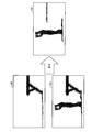
- FIG. 23 is a diagram for explaining an example of edge noise. As shown in FIG. 23, when the sensor 10 measures the three-dimensional point group of the subject 1, the three-dimensional point group 1a is measured. The three-dimensional point cloud 1a includes edge noise 1b.
- Edge noise 1b is generated when the laser beam is in a faint state on the contour portion of the subject 1 at the time of measurement. That is, although the edge noise 1b is a point indicating the contour of the subject 1, the distance value in the depth direction is measured as a position farther than the distance value of the subject 1, and the three-dimensional point cloud constituting the subject 1 is formed. It will be farther than 1a.
- the accuracy will be reduced in the subsequent processing, so it is necessary to deal with the edge noise.
- a conventional technique for dealing with edge noise for example, there are a conventional technique 1 and a conventional technique 2.
- FIG. 24 is a diagram for explaining the prior art 1.
- the point cloud density is calculated by obtaining the distance from another point for each point included in the three-dimensional point cloud 1a.
- the point cloud density indicates the number of points included in a circle having a predetermined radius centered on the target point.
- the points whose point cloud density is equal to or higher than the threshold value are left, and the points whose point cloud density is lower than the threshold value are deleted.
- the point 2a has many points around the point 2a, and the point cloud density is equal to or higher than the threshold value. Therefore, the prior art 1 leaves the point 2a.
- the point 2b there are few points existing around the point 2b, and the point cloud density is less than the threshold value. Therefore, the prior art 1 deletes the point 2b.
- the edge noise 1b is deleted by repeatedly executing the above processing for each point in the three-dimensional point cloud 1a.
- Conventional technology 2 is a technology for correcting edge noise.
- two RGB stereo images are taken, and the outline of the subject is extracted based on the stereo images.
- the contour position on the depth image is specified by the contour position of the subject using a stereo image, and the value of the depth image is based on the distance between two points straddling the contour. To correct.
- Conventional technique 1 is a technique for deleting points based on the point cloud density, but the number of three-dimensional point clouds that can be used in the subsequent processing is reduced. For example, when the resolution of the sensor is low or the distance between the subject and the sensor is large, the number of three-dimensional point clouds is originally small. Further, the number of three-dimensional point clouds corresponding to a portion where the area of the subject visible from the 3D sensor is small (for example, a human arm) is small. Therefore, if the edge noise related to the contour of the subject is simply removed, the contour and shape of the subject cannot be maintained correctly with only the remaining point cloud.
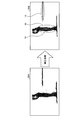
- FIG. 25 is a diagram for explaining the problems of the prior art 1.
- points are simply deleted based on the point cloud density, not only the edge noise 1b but also the point cloud 1c is deleted. This is because there are few points around the point cloud 1c and the point cloud density is less than the threshold value.
- the point cloud 1c is a point cloud corresponding to the human arm as the subject, and the original arm of the subject is not maintained due to the deletion of the point cloud 1c.
- the prior art 2 is a technique for correcting edge noise, it is possible to maintain the number of three-dimensional point clouds, but the contour of the subject is specified by a stereo image separately from the depth image. Is a prerequisite. Therefore, it is difficult to correct the edge noise in the situation where the stereo image cannot be used.
- the present invention provides a correction method, a correction program, and an information processing system that can leave points corresponding to edge noise among the noise of the three-dimensional point cloud measured by the sensor as points of the contour of the subject.
- the purpose is to provide.
- the computer executes the following processing.
- the computer generates a distance image based on the measurement data of the 3D sensor.
- the computer identifies a plurality of first pixels corresponding to a point cloud of the outline of the subject among the pixels included in the distance image.
- the computer identifies a plurality of second pixels included in a predetermined range from the plurality of first pixels among the pixels included in the distance image.
- the computer corrects the first coordinate information of the first point cloud corresponding to the plurality of first pixels in the measurement data based on the second coordinate information of the second point cloud corresponding to the plurality of second pixels.
- the computer outputs the coordinate information of the point cloud constituting the subject including the first point cloud corrected with the first coordinate information.
- the points corresponding to the edge noise can be left as the points of the contour of the subject.
- FIG. 1 is a diagram showing an example of an information processing system according to this embodiment.
- FIG. 2 is a diagram for explaining an example of processing of the information processing system according to the present embodiment.
- FIG. 3 is a diagram for explaining an example of background subtraction.
- FIG. 4 is a diagram for explaining an example of the correction process.
- FIG. 5 is a diagram showing an example of skeleton recognition.
- FIG. 6 is a diagram showing an example of point cloud clustering.
- FIG. 7 is a diagram showing an example of fitting.
- FIG. 8 is a functional block diagram showing the configuration of the information processing apparatus according to the present embodiment.
- FIG. 9 is a diagram for explaining the focal length fx in the x-axis direction.
- FIG. 10 is a diagram for explaining the focal length fy in the y-axis direction.
- FIG. 11 is a diagram showing an example of a correction processing unit.
- FIG. 12 is a diagram for explaining a process of generating a 2.5D image.
- FIG. 13 is a diagram for explaining a process of identifying the first pixel.
- FIG. 14 is a diagram showing the relationship between w and z used for calculating the distance ix.
- FIG. 15 is a diagram showing the relationship between h and z used for calculating the distance ii.
- FIG. 16 is a diagram (1) for explaining the correction process.
- FIG. 17 is a diagram (2) for explaining the correction process.
- FIG. 18 is a diagram for explaining the relationship between the points before correction and the points after correction.
- FIG. 19 is a flowchart (1) showing a processing procedure of the correction processing unit according to the present embodiment.
- FIG. 19 is a flowchart (1) showing a processing procedure of the correction processing unit according to the present embodiment.
- FIG. 19 is a flowchart (1) showing a processing procedure of the correction processing unit according to the
- FIG. 20 is a flowchart (2) showing a processing procedure of the correction processing unit according to the present embodiment.
- FIG. 21 is a diagram for explaining the effect of this embodiment.
- FIG. 22 is a diagram showing an example of a hardware configuration of a computer that realizes a function similar to that of an information processing device.
- FIG. 23 is a diagram for explaining an example of edge noise.
- FIG. 24 is a diagram for explaining the prior art 1.
- FIG. 25 is a diagram for explaining the problems of the prior art 1.
- FIG. 1 is a diagram showing an example of an information processing system according to this embodiment. As shown in FIG. 1, this information processing system includes sensors 11a, 11b, 11c, 11d and an information processing device 100. The sensors 11a to 11d and the information processing device 100 are connected by wire or wirelessly.
- the subject 1 is supposed to perform on an instrument, but the present invention is not limited to this.
- the subject 1 may perform an act in a place where no instrument is present, or may perform an action other than the act.
- the sensor 11a is a measuring device (laser sensor) that measures the distance between the point cloud constituting the subject 1 and the sensor 11a.
- the sensor 11a outputs the distance image data as the measurement result to the information processing device 100.
- the sensor 11a performs a raster scan and measures the distance between the point cloud and the sensor 11a.
- sensors 11b to 11d The description of the sensors 11b to 11d is the same as the description of the sensor 11a. In the following description, the sensors 11a to 11d are collectively referred to as "sensor 11".
- FIG. 2 is a diagram for explaining an example of processing of the information processing apparatus according to this embodiment.
- the information processing apparatus 100 executes the processes of steps S10 to S15 described below.
- the processing (background subtraction) in step S10 will be described.
- the information processing device 100 removes background noise by calculating the difference between the background image and the distance image acquired from the sensor 11, and generates data of the distance image from which the background noise has been removed.
- the background image is a distance image measured by the sensor 11 in a situation where the subject 1 does not exist.
- FIG. 3 is a diagram for explaining an example of background subtraction. As shown in FIG. 3, the information processing apparatus 100 generates the distance image 12C by calculating the difference between the background image 12B and the distance image 12A.
- the information processing device 100 converts the data of the distance image 12C into the three-dimensional point cloud data 20A.
- the three-dimensional point cloud data 20A is obtained by converting the relationship between the point and the distance included in the distance image 12C into the relationship between the point and the coordinates of the three-dimensional Cartesian coordinate system.
- the three-dimensional Cartesian coordinate system includes an x-axis, a y-axis, and a z-axis, and the z-axis is an axis in the depth direction of the sensor 11.
- the coordinates of the three-dimensional Cartesian coordinate system are referred to as "three-dimensional coordinates".
- step S11 The process (correction process) of step S11 will be described.
- the information processing device 100 generates the three-dimensional point cloud data 20B by correcting the edge noise included in the three-dimensional point cloud data 20A.
- FIG. 4 is a diagram for explaining an example of correction processing.
- the information processing apparatus 100 generates the three-dimensional point cloud data 20B by executing the correction process on the three-dimensional point cloud data 20A. Comparing the three-dimensional point cloud data 20A and the three-dimensional point cloud data 20B, the coordinates of the edge noise in the contour portion 13 are corrected near the surface of the subject or the instrument. A detailed description of the correction process will be described later.
- step S12 The process of step S12 (2.5D (Dimension) conversion) will be described.
- the information processing device 100 generates 2.5D image data 21 by projecting the three-dimensional point cloud data 20B onto a two-dimensional map. Each pixel of the image data 21 is associated with a point cloud of the three-dimensional point cloud data 20B. The z-axis value of the corresponding point is set in the pixel of the image data 21.
- the process (recognition process) of step S13A will be described.
- the information processing device 100 generates the joint heat map 22 by inputting the 2.5D image data 21 into the learning model that has been learned in advance.
- the joint heat map 22 is information indicating the position of each joint of the subject 1.
- step S13B point cloud integration
- the information processing device 100 integrates the three-dimensional point cloud data 20B (a plurality of three-dimensional point cloud data 20B measured by each sensor 11 and a plurality of corrected three-dimensional point cloud data 20B).
- One 3D point cloud data 20C is generated.
- the information processing apparatus 100 may execute the process of step S13A and the process of step S13B in parallel.
- the process (skeleton recognition) of step S14A will be described.
- the information processing device 100 generates the skeleton recognition result 23 based on the position of each joint shown in the joint heat map 22.
- the skeleton recognition result 23 is information in which the coordinates of each joint are connected.
- FIG. 5 is a diagram showing an example of skeleton recognition.
- the skeleton recognition result 23 combined with the three-dimensional point cloud data is shown.
- noise under the feet of the subject 1 such as matte noise
- the skeleton positions between the knees and the toes become abnormal in the skeleton recognition result 23.
- step S14B point cloud clustering
- the information processing device 100 classifies the three-dimensional point cloud data 20C into a plurality of clusters by executing point cloud clustering.
- the information processing apparatus 100 deletes the point cloud included in the cluster in which the number of points in the point cloud cluster is less than the threshold value among the plurality of clusters as noise.
- the point cloud included in the cluster in which the volume of the polyhedron formed by the point cloud cluster is less than the threshold value may be deleted as noise.
- FIG. 6 is a diagram showing an example of point cloud clustering. As shown in FIG. 6, the three-dimensional point cloud data 20D is generated by executing the point cloud clustering on the three-dimensional point cloud data 20C and removing the noise 14.
- the information processing apparatus 100 may execute the process of step S14A and the process of step S14B in parallel.
- FIG. 7 is a diagram showing an example of fitting.
- the information processing apparatus 100 sets the initial position by applying the cylindrical model 16 to the skeleton recognition result 23 described in step S14A.
- the cylindrical model is model data in which each part of the subject 1 is represented by a cylinder (or an elliptical pillar or the like).
- the information processing device 100 gradually changes the angle of the connecting portion of each cylinder of the cylinder model 16 and adjusts (fitting) so that the distance between the surface of the cylinder model and each point of the three-dimensional point cloud data 20D becomes closer. Execute.
- the information processing device 100 generates a skeleton model 24 in which the axes of the fitted cylindrical model 16 are connected.
- the information processing device 100 repeatedly executes the processes of steps S10 to S15 every time the distance image data is acquired from the sensor 11, and repeatedly executes the process of generating the skeleton model 24.
- the information processing device 100 outputs the skeleton model 24 in chronological order, and executes skill certification, scoring, and the like of various competitions based on the transition of the joint positions of the skeleton model 24 at each time.
- FIG. 8 is a functional block diagram showing the configuration of the information processing apparatus according to the present embodiment.
- the information processing device 100 includes a communication unit 110, an input unit 120, a display unit 130, a storage unit 140, and a control unit 150.
- the communication unit 110 is a processing unit that receives distance image data from the sensor 11 shown in FIG.
- the communication unit 110 outputs the received distance image data to the control unit 150.
- the communication unit 110 is an example of a communication device.
- the input unit 120 is an input device that inputs various information to the information processing device 100.
- the input unit 120 corresponds to a keyboard, a mouse, a touch panel, and the like.
- the user operates the input unit 120 to request the display of the display screen.
- the display unit 130 is a display device that displays information output from the control unit 150. For example, the display unit 130 displays skill certification, scoring results, etc. of various competitions.
- the display unit 130 corresponds to a liquid crystal display, an organic EL (Electro-Luminescence) display, a touch panel, and the like.
- the storage unit 140 has a background image table 141, a measurement table 142, and a sensor parameter 143.
- the storage unit 140 corresponds to semiconductor memory elements such as RAM (Random Access Memory) and flash memory (Flash Memory), and storage devices such as HDD (Hard Disk Drive).
- the background image table 141 is a table that stores background image data (distance image data) measured by each of the sensors 11a to 11d in a state where the subject 1 does not exist.
- the measurement table 142 is a table that stores the data of the distance images measured by the sensors 11a to 11d in the presence of the subject 1.
- the sensor parameter 143 has the parameters of the sensors 11a to 11d, respectively.
- the sensor parameter 143 includes the x-axis and y-axis angles of view ⁇ x, ⁇ y, x-axis, and y-axis focal lengths fx and fy. Further, the sensor parameter 143 includes width and high.
- FIG. 9 is a diagram for explaining the focal length fx in the x-axis direction.
- FIG. 9 shows a case where the sensor 11 is viewed from above.
- the relationship between the focal length fx and the angle of view ⁇ x is expressed by Eq. (1).
- the width is a preset horizontal width and corresponds to the number of pixels in the horizontal direction (i-axis direction) of the 2.5D image described later.
- FIG. 10 is a diagram for explaining the focal length fy in the y-axis direction.
- FIG. 10 shows a case where the sensor 11 is viewed from the side.
- the relationship between the focal length fy and the angle of view ⁇ y is expressed by the equation (2).
- the height is a preset height, and corresponds to the number of pixels in the vertical direction (j-axis direction) of the 2.5D image described later.
- the control unit 150 includes an acquisition unit 151, a correction processing unit 152, a fitting processing unit 153, and an evaluation unit 154.
- the control unit 150 is realized by hard-wired logic such as CPU (Central Processing Unit), MPU (Micro Processing Unit), ASIC (Application Specific Integrated Circuit), FPGA (Field Programmable Gate Array), and the like.
- the acquisition unit 151 is a processing unit that acquires distance image data from the sensor 11 via the communication unit 110.
- the acquisition unit 151 stores the data of the distance image in the measurement table 142.
- the acquisition unit 151 divides the distance image data measured by the sensors 11a to 11d into distinguishable ones and stores the distance image data in the measurement table 142.
- the correction processing unit 152 is a processing unit that executes the background subtraction described in step S10 of FIG. 2 and the correction processing described in step S11.
- FIG. 11 is a diagram showing an example of a correction processing unit.
- the correction processing unit 152 includes a generation unit 152a, a specific unit 152b, a correction unit 152c, and an output control unit 152d.
- the correction processing unit 152 executes the correction processing for each distance image measured by the sensors 11a to 11d, but for convenience of explanation, a case where the distance image measured by the sensor 11a is corrected will be described.
- the process of correcting each distance image measured by the sensors 11b to 11d is the same as the process of correcting the distance image measured by the sensors 11a.
- the generation unit 152a is a processing unit that calculates the distance image 12C which is the difference between the distance image 12A measured by the sensor 11a and the background image 12B corresponding to the sensor 11a.
- the generation unit 152a acquires the data of the distance image 12A from the measurement table 142.
- the generation unit 152a acquires the data of the background image 12B from the background image table 141.
- the data of the distance image 12C is data showing the relationship between the points included in the point cloud and the distance.
- the generation unit 152a converts the data of the distance image 12C into the three-dimensional point cloud data by using the conversion table (not shown) that defines the relationship between the distance and the three-dimensional coordinates.
- the three-dimensional point cloud data associates the points included in the point cloud with the three-dimensional coordinates.
- the generation unit 152a outputs the three-dimensional point cloud data to the specific unit 152b.
- the three-dimensional point cloud data corresponds to "measurement data".
- the generation unit 152a repeatedly executes the above process every time the data of the distance image 12A measured by the sensor 11a is stored in the measurement table 142.
- the specific unit 152b generates a 2.5D image based on the three-dimensional point cloud data, and among the pixels included in the 2.5D image, a plurality of first pixels corresponding to the point cloud of the contour of the subject 1 are selected. It is a processing unit to be specified.
- the 2.5D image corresponds to a "distance image”.
- FIG. 12 is a diagram for explaining a process of generating a 2.5D image.
- the specific unit 152b maps each point of the three-dimensional point cloud data 30a to each pixel of the two-dimensional (i-axis, j-axis) 2.5D image 30b.
- the z-axis value of the corresponding point is set in the pixel of the 2.5D image 30b.
- some point clouds included in the three-dimensional point cloud data 30a are not shown.
- the pixel corresponding to the point 31a is the pixel 31b, and the z-axis value of the point 31a is set in the pixel 31b.
- the value on the z-axis is appropriately referred to as a “distance value”.
- the distance value Z corresponding to the position (i, j) of the 2.5D image is defined by the equation (3).
- the range of the value of i is "0 to wid”.
- the range of the value of j is "0 to height”.
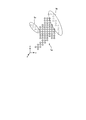
- FIG. 13 is a diagram for explaining a process of identifying the first pixel.
- the specific unit 152b scans the 2.5D image 30b and extracts the contour portion 31c from the plurality of pixels in which the distance value included in the 2.5D image 30b is set.
- the pixel included in the contour portion 31c corresponds to the "first pixel".
- the width of the contour portion may be given as a constant in advance.
- the specific unit 152b outputs the data of the 2.5D image 30b and the data of the contour portion 31c to the correction unit 152c.
- the specific unit 152b outputs data in which each point of the three-dimensional point cloud data 30a is associated with each pixel of the 2.5D image 30b to the correction unit 152c.
- the specific unit 152b repeatedly executes the above process every time the three-dimensional point cloud data is acquired from the generation unit 152a.
- the correction unit 152c identifies a plurality of second pixels included in a predetermined range from the first pixel among the pixels included in the 2.5D image, and the first coordinates of the first point cloud corresponding to the plurality of first pixels. This is a processing unit that corrects information with the second coordinate information of a second point cloud corresponding to a plurality of second pixels. For example, the correction unit 152c sequentially executes a process of calculating the focal lengths fx and fy, a process of calculating the distances ix and ii, and a process of correcting.
- the correction unit 152c calculates the focal length fx based on the angle of view ⁇ x stored in the sensor parameter 143, the width, and the equation (1).
- the correction unit 152c calculates the focal length fy based on the angle of view ⁇ y stored in the sensor parameter 143, the height, and the equation (2).
- the focal lengths fx and fy may be calculated in advance, and the focal lengths fx and fy calculated in advance may be included in the sensor parameter 143.
- the correction unit 152c skips the process of calculating the focal lengths fx and fy.
- the distance ix indicates the distance of one pixel on the i-axis of the 2.5D image.
- the distance ii indicates the distance of one pixel on the j-axis of the 2.5D image.
- the correction unit 152c calculates the distance ix based on the equations (4) and (5).
- FIG. 14 is a diagram showing the relationship between w and z used for calculating the distance ix.
- w indicates the width of the three-dimensional space that can be measured by the sensor 11.
- z indicates the depth of the three-dimensional space that can be measured by the sensor 11. The value of z may be preset.
- the correction unit 152c calculates the distance ii based on the equations (6) and (7).
- FIG. 15 is a diagram showing the relationship between h and z used for calculating the distance ii.
- h indicates the height of the three-dimensional space that can be measured by the sensor 11.
- z indicates the depth of the three-dimensional space that can be measured by the sensor 11. The value of z may be preset.
- FIG. 16 is a diagram (1) for explaining the correction process.
- the correction unit 152c selects one first pixel among the plurality of first pixels as the "focused pixel" based on the 2.5D image 30b and the contour portion 31c.
- the correction unit 152c identifies pixels included in radii rx and ry centered on the pixel of interest. It is assumed that the values of the radii rx and ry are set in advance.
- the point of the three-dimensional point cloud data 30a corresponding to the pixel of interest of the 2.5D image 30b is the point of interest.
- the pixel of interest is pixel A.
- the values of the radii rx and ry are set to "0.04 m", respectively. Let the distance ix calculated by the formulas (4) and (5) be "0.001 m”. The distance iy calculated by the formulas (6) and (7) is set to "0.002 m”.
- the values of the radii rx and ry can be changed as appropriate. For example, the values of the radii rx and ry may be "0.05 m".
- the correction unit 152c sets a range 31d of radii rx and ry centered on the pixel A.
- the pixels included in the range 31d are defined as peripheral pixels.
- the point of the three-dimensional point cloud data corresponding to the peripheral pixel is defined as the peripheral point.
- the correction unit 152c identifies a plurality of non-contoured pixels among the peripheral pixels.
- FIG. 17 is a diagram (2) for explaining the correction process.
- a plurality of pixels in the non-contoured portion are pixels included in the range 31e.
- the correction unit 152c corrects the three-dimensional coordinates of the point corresponding to the pixel A based on the three-dimensional coordinates corresponding to a plurality of pixels in the non-contour portion.
- the three-dimensional coordinates of the points (points of interest) corresponding to the pixel A before correction are set to "pc [A] .x, pc [A] .y, pc [A] .z".
- the corrected three-dimensional coordinates of the point (point of interest) corresponding to the pixel A are set to "pc [A] .x', pc [A] .y', pc [A] .z'".
- the correction unit 152c specifies the absolute value of the z-axis value corresponding to a plurality of pixels in the non-contour portion, and among the specified absolute values, the minimum absolute value is set to pc [A]. Set to the value of z'. Alternatively, the correction unit 152c calculates the average value of the z-axis values corresponding to the plurality of pixels in the non-contour portion, and the calculated average value is set to pc [A]. Set to the value of z'.
- the correction unit 152c has a pc [A]. z'and pc [A]. Based on the ratio to z, pc [A]. x'and pc [A]. Calculate y'.
- the correction unit 152c is based on the equation (8) and has a pc [A].
- the correction unit 152c is based on the equation (9) and has a pc [A]. Calculate y'.
- the correction unit 152c corresponds to a plurality of first pixels included in the contour portion 31c by selecting an unselected first pixel as a pixel of interest from the plurality of first pixels and repeatedly executing the above processing. The process of correcting the three-dimensional coordinates of the point of interest is repeatedly executed. By the processing of the correction unit 152c, the three-dimensional coordinates of the edge noise included in the three-dimensional point cloud data 30a are corrected. The correction unit 152c outputs the three-dimensional point cloud data 30a corrected for the three-dimensional coordinates to the output control unit 152d.
- FIG. 18 is a diagram for explaining the relationship between the points before correction and the points after correction.
- the figure on the left side of FIG. 18 is a view of the points viewed from above.
- the figure on the right side of FIG. 18 is a side view of the points.
- Let the point before correction be point A.
- Let the corrected point be point C.
- the point where only the value of the Z axis is corrected is defined as the point B.
- O is the position of the sensor 11.
- the coordinates of points A, B, and C are as shown below.
- A (x, y, z)
- B (x, y, z')
- C (x', y', z')
- Point B in which only the Z-axis value of point A is corrected, does not exist on the straight line OA between the sensor position O and point A, so it is not corrected to an appropriate position. It is correct to correct the point B to the position of the point C existing on the straight line OA.
- Equations (10), (11), and (12) are derived from the similar relationship between the triangle ABC and the triangle OCD. Equation (12) corresponds to Equation (8).
- Equations (13), (14), and (15) are derived from the similar relationship between the triangle ABC and the triangle OCD. Equation (15) corresponds to equation (9).
- the output control unit 152d is a processing unit that outputs the corrected three-dimensional point cloud data acquired from the correction unit 152c to the fitting processing unit 153.
- the above-mentioned specific unit 152b generates a 2.5D image again based on the three-dimensional point cloud data corrected by the correction unit 152c, identifies the first pixel included in the contour portion, and corrects the correction unit.
- the process of correcting the first pixel again by 152c may be repeatedly executed L times. L is preset.
- the fitting processing unit 153 is a processing unit that executes 2.5D conversion, recognition processing, point cloud integration, skeleton recognition, point cloud clustering, and fitting described in S12 to S15 of FIG. 2, respectively.
- the fitting processing unit 153 outputs the skeleton model 24 to the evaluation unit 154.
- the fitting processing unit 153 Each time the fitting processing unit 153 acquires the corrected three-dimensional point cloud data from the output control unit 152d, the fitting processing unit 153 repeatedly executes the above processing and outputs the skeleton model 24.
- the evaluation unit 154 is a processing unit that acquires the skeleton model 24 in time series and evaluates the performance of the subject 1 based on the transition of each joint coordinate of the skeleton model. For example, the evaluation unit 154 evaluates the performance of the subject 1 using a table that defines the transition of each joint coordinate, the type of the technique, and the establishment or failure of the technique, and outputs the evaluation result to the display unit 130 for display. ..
- scoring competitions include trampoline, swimming dive, figure skating, karate kata, social dance, snowboarding, skateboarding, ski aerial, and surfing. It may also be applied to classical ballet, ski jumping, mogul air, turns, baseball, basketball form checks, and the like. It may also be applied to competitions such as kendo, judo, wrestling, and sumo. Furthermore, it can be used to evaluate whether or not the weightlifting barbell has been raised.
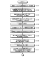
- FIG. 19 and 20 are flowcharts showing a processing procedure of the correction processing unit according to the present embodiment.
- the generation unit 152a of the correction processing unit 152 acquires the data of the distance image from the measurement table 142 (step S101).
- the generation unit 152a calculates the difference between the distance image and the background image, and generates the data of the distance image (difference image) (step S102).
- the generation unit 152a converts the data of the distance image (difference image) into the three-dimensional point cloud data (step S103).
- the specific unit 152b of the correction processing unit 152 generates 2.5D image data by mapping the three-dimensional point cloud data (step S104).
- the correction processing unit 152 repeatedly executes the processes from step S105 to step S121 L times.
- the specific unit 152b applies contour extraction to the data of the 2.5D image (step S106).
- the correction unit 152c of the correction processing unit 152 sets the pixel of interest in the contour portion (step S107).
- the correction unit 152c calculates the focal lengths fx and fy from the angles of view ⁇ x and ⁇ y of the x-axis and the y-axis, respectively (step S108).
- the correction unit 152c calculates the x-axis and y-axis distances ix and ii per 2.5D pixel (step S109).
- the correction unit 152c repeatedly executes the processes from step S110 to step S120 for all the points of interest.
- the correction unit 152c extracts pixels included in a rectangle having radii rx and ry with reference to the pixel of interest on the 2.5D image as peripheral pixels (step S111), and proceeds to the process of step S112 in FIG.
- the correction unit 152c repeatedly executes the processes from step S112 to step S116 for all peripheral pixels.
- the correction unit 152c specifies the attributes (contour, non-contour) of peripheral pixels (step S113).
- the correction unit 152c specifies the attributes (contour, non-contour) of peripheral pixels (step S113). When the attribute of the peripheral pixel is a contour (step S114, Yes), the correction unit 152c shifts to step S116.
- step S114 when the attribute of the peripheral pixel is not a contour (step S114, No), the correction unit 152c registers the value of the z-axis of the peripheral pixel in the buffer (not shown) (step S115).
- the correction unit 152c corrects the z value of the point of interest based on the calculation result (minimum value or average value of the absolute value) (step S118).
- the correction unit 152c corrects the x-axis value and the y-axis value of the point of interest based on the correction result of the z-axis (step S119).
- the output control unit 152d of the correction processing unit 152 outputs the corrected three-dimensional point cloud data to the fitting processing unit 153 (step S122).
- the information processing device 100 identifies a plurality of first pixels corresponding to contours in a 2.5D image, and among the pixels included in the 2.5D image, a plurality of second pixels included in a predetermined range from the first pixel. To identify.
- the information processing device 100 corrects the three-dimensional coordinates of the first point cloud corresponding to the plurality of first pixels with the three-dimensional coordinates of the second point cloud corresponding to the plurality of second pixels. As a result, among the noise of the three-dimensional point cloud measured by the sensor, the point corresponding to the edge noise can be left as the point of the contour of the subject.
- the points corresponding to the edge noise can be left as the points of the contour of the subject, so that the accuracy of fitting to the corrected 3D point cloud data can be improved.
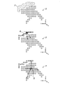
- FIG. 21 is a diagram for explaining the effect of this embodiment.
- the point cloud 40a in FIG. 21 shows the uncorrected three-dimensional point cloud data.
- the skeleton model when fitting is executed for this point cloud 40a is the skeleton model 41a.
- the accuracy of the joint positions of the head and the left arm is lowered due to the influence of the noise 50a.
- the point cloud 40b in FIG. 21 is, for example, a point cloud in which noise is removed by the prior art 1 with respect to the three-dimensional point cloud data.
- the noise 50a and the point cloud 50b are deleted from the point cloud 40b.
- the removal of the noise 50a is as expected.
- the point cloud 50b is a point cloud corresponding to the leg portion of the subject 1
- the point cloud of the foot of the subject 1 has disappeared. Therefore, the skeleton model when fitting is executed for the point cloud 40b is the skeleton model 41b.
- the skeleton model 41b since the point cloud of the foot disappears from the point cloud 40b, the accuracy of the joint position of the foot is lowered.
- the point cloud 40c in FIG. 21 is, for example, a point cloud in which noise is removed by the point cloud clustering in FIG. 2 after being corrected by the correction processing unit 152. From the point cloud 40b, the point cloud 50b is not removed, and the noise 50a is removed.
- the correction processing unit 152 can leave a point cloud of the foot of the subject 1. Therefore, the skeleton model when fitting is executed for the point cloud 40c is the skeleton model 41c.
- the skeleton model 41c accurately reproduces each joint position of the subject 1.
- the information processing device 100 specifies as a second pixel a pixel included in the 2.5D image, which is included in the radii rx and ry with reference to the pixel of interest and does not correspond to the point cloud of the contour.
- the information processing device 100 calculates the minimum value or the average value of the absolute value based on the z-axis values of the plurality of second pixels, and the calculated values are used to obtain the three-dimensional coordinates (z-axis value) of the point of interest. To correct. As a result, it is possible to correct the value of the z-axis of the edge noise to be closer to the coordinates of the point cloud of the subject 1.
- the information processing device 100 corrects the three-dimensional coordinates (x-axis value, y-coordinate value) of the point of interest based on the corrected z-axis value. As a result, the three-dimensional coordinates of the point of interest after correction can be corrected to a more appropriate position.
- the information processing device 100 again generates a 2.5D image based on the three-dimensional point cloud data corrected by the correction unit 152b, and identifies the first pixel included in the contour portion.
- the correction unit 152c repeatedly executes the process of correcting the first pixel again L times. Thereby, the edge noise existing around the subject 1 can be corrected.
- the correction processing unit 152 when the correction processing unit 152 performs contour extraction, two pixels from the outermost pixel among the plurality of pixels for which the distance value included in the 2.5D image 30b is set are used as the contour. Although it was extracted, it is not limited to this, and may be 3 pixels.
- FIG. 22 is a diagram showing an example of a hardware configuration of a computer that realizes a function similar to that of an information processing device.
- the computer 200 has a CPU 201 that executes various arithmetic processes, an input device 202 that receives data input from a user, and a display 203. Further, the computer 200 has a communication device 204 for receiving the measurement result from the sensor, and an interface device 205 for connecting to various devices. The computer 200 has a RAM 206 for temporarily storing various information and a hard disk device 207. Then, each device 201 to 207 is connected to the bus 208.
- the hard disk device 207 has an acquisition program 207a, a correction program 207b, a fitting processing program 207c, and an evaluation program 207d.
- the CPU 201 reads the acquisition program 207a, the correction program 207b, the fitting processing program 207c, and the evaluation program 207d and deploys them in the RAM 206.
- the acquisition program 207a functions as the acquisition process 206a.
- the correction program 207b functions as the correction process 206b.
- the fitting processing program 207c functions as the fitting processing process 206c.
- the evaluation program 207d functions as the evaluation process 206d.
- the processing of the acquisition process 206a corresponds to the processing of the acquisition unit 151.
- the processing of the correction process 206b corresponds to the processing of the correction processing unit 152.
- the correction processing unit 152 includes a generation unit 152a, a specific unit 152b, a correction unit 152c, and an output control unit 152d.
- the processing of the evaluation process 206a corresponds to the processing of the evaluation unit 207d.
- each program 207a to 207d does not necessarily have to be stored in the hard disk device 207 from the beginning.
- each program is stored in a "portable physical medium" such as a flexible disk (FD), a CD-ROM, a DVD disk, a magneto-optical disk, or an IC card inserted into the computer 200. Then, the computer 200 may read and execute each of the programs 207a to 207d.
Landscapes
- Engineering & Computer Science (AREA)
- Physics & Mathematics (AREA)
- General Physics & Mathematics (AREA)
- Theoretical Computer Science (AREA)
- Computer Vision & Pattern Recognition (AREA)
- Optics & Photonics (AREA)
- Computer Networks & Wireless Communication (AREA)
- Electromagnetism (AREA)
- Radar, Positioning & Navigation (AREA)
- Remote Sensing (AREA)
- Length Measuring Devices By Optical Means (AREA)
Priority Applications (5)
| Application Number | Priority Date | Filing Date | Title |
|---|---|---|---|
| EP19947816.5A EP4040103A4 (en) | 2019-10-02 | 2019-10-02 | CORRECTION PROCEDURES, CORRECTION PROGRAM AND INFORMATION HANDLING SYSTEM |
| CN201980100928.8A CN114450550A (zh) | 2019-10-02 | 2019-10-02 | 校正方法、校正程序以及信息处理系统 |
| PCT/JP2019/038979 WO2021064912A1 (ja) | 2019-10-02 | 2019-10-02 | 補正方法、補正プログラムおよび情報処理システム |
| JP2021550855A JP7327494B2 (ja) | 2019-10-02 | 2019-10-02 | 補正方法、補正プログラムおよび情報処理システム |
| US17/699,295 US20220206156A1 (en) | 2019-10-02 | 2022-03-21 | Correction method, non-transitory computer-readable storage medium for storing correction program, and information processing device |
Applications Claiming Priority (1)
| Application Number | Priority Date | Filing Date | Title |
|---|---|---|---|
| PCT/JP2019/038979 WO2021064912A1 (ja) | 2019-10-02 | 2019-10-02 | 補正方法、補正プログラムおよび情報処理システム |
Related Child Applications (1)
| Application Number | Title | Priority Date | Filing Date |
|---|---|---|---|
| US17/699,295 Continuation US20220206156A1 (en) | 2019-10-02 | 2022-03-21 | Correction method, non-transitory computer-readable storage medium for storing correction program, and information processing device |
Publications (1)
| Publication Number | Publication Date |
|---|---|
| WO2021064912A1 true WO2021064912A1 (ja) | 2021-04-08 |
Family
ID=75337124
Family Applications (1)
| Application Number | Title | Priority Date | Filing Date |
|---|---|---|---|
| PCT/JP2019/038979 Ceased WO2021064912A1 (ja) | 2019-10-02 | 2019-10-02 | 補正方法、補正プログラムおよび情報処理システム |
Country Status (5)
| Country | Link |
|---|---|
| US (1) | US20220206156A1 (https=) |
| EP (1) | EP4040103A4 (https=) |
| JP (1) | JP7327494B2 (https=) |
| CN (1) | CN114450550A (https=) |
| WO (1) | WO2021064912A1 (https=) |
Cited By (3)
| Publication number | Priority date | Publication date | Assignee | Title |
|---|---|---|---|---|
| CN114581319A (zh) * | 2022-01-27 | 2022-06-03 | 北京旷视科技有限公司 | 图像矫正方法、装置、电子设备和计算机可读介质 |
| JP2022184769A (ja) * | 2021-06-01 | 2022-12-13 | 富士通株式会社 | 無線レーダ信号に基づくキーポイント修正装置及び方法 |
| JP7319751B1 (ja) | 2023-04-12 | 2023-08-02 | 株式会社Knowhere | コンピュータ、プログラム、情報処理方法およびモデル生成方法 |
Families Citing this family (1)
| Publication number | Priority date | Publication date | Assignee | Title |
|---|---|---|---|---|
| US11816855B2 (en) * | 2020-02-11 | 2023-11-14 | Samsung Electronics Co., Ltd. | Array-based depth estimation |
Citations (4)
| Publication number | Priority date | Publication date | Assignee | Title |
|---|---|---|---|---|
| JP2012079251A (ja) | 2010-10-06 | 2012-04-19 | Konica Minolta Holdings Inc | 画像処理装置及び画像処理システム |
| JP2014102243A (ja) * | 2012-10-24 | 2014-06-05 | Nikon Corp | 形状測定装置、構造物製造システム、形状測定方法、構造物製造方法、及びそのプログラム |
| WO2018185807A1 (ja) * | 2017-04-03 | 2018-10-11 | 富士通株式会社 | 距離情報処理装置、距離情報処理方法および距離情報処理プログラム |
| WO2019087404A1 (ja) | 2017-11-06 | 2019-05-09 | 富士通株式会社 | 算出方法、算出プログラムおよび情報処理装置 |
Family Cites Families (5)
| Publication number | Priority date | Publication date | Assignee | Title |
|---|---|---|---|---|
| US7876906B2 (en) * | 2006-05-30 | 2011-01-25 | Sonitus Medical, Inc. | Methods and apparatus for processing audio signals |
| JP2010212788A (ja) * | 2009-03-06 | 2010-09-24 | Sharp Corp | 撮像装置、欠陥画素補正方法、および電子情報機器 |
| JP5560771B2 (ja) * | 2010-02-26 | 2014-07-30 | セイコーエプソン株式会社 | 画像補正装置、画像表示システム、画像補正方法 |
| KR101554241B1 (ko) * | 2011-06-24 | 2015-09-18 | 소프트키네틱 소프트웨어 | 3차원 이미지에서의 결함성 픽셀 깊이 데이터 값의 깊이 맵 품질 향상을 위한 방법 |
| CN102324041B (zh) * | 2011-09-09 | 2014-12-03 | 深圳泰山在线科技有限公司 | 像素归类方法、关节体姿态识别方法及鼠标指令生成方法 |
-
2019
- 2019-10-02 WO PCT/JP2019/038979 patent/WO2021064912A1/ja not_active Ceased
- 2019-10-02 CN CN201980100928.8A patent/CN114450550A/zh active Pending
- 2019-10-02 EP EP19947816.5A patent/EP4040103A4/en not_active Withdrawn
- 2019-10-02 JP JP2021550855A patent/JP7327494B2/ja active Active
-
2022
- 2022-03-21 US US17/699,295 patent/US20220206156A1/en not_active Abandoned
Patent Citations (4)
| Publication number | Priority date | Publication date | Assignee | Title |
|---|---|---|---|---|
| JP2012079251A (ja) | 2010-10-06 | 2012-04-19 | Konica Minolta Holdings Inc | 画像処理装置及び画像処理システム |
| JP2014102243A (ja) * | 2012-10-24 | 2014-06-05 | Nikon Corp | 形状測定装置、構造物製造システム、形状測定方法、構造物製造方法、及びそのプログラム |
| WO2018185807A1 (ja) * | 2017-04-03 | 2018-10-11 | 富士通株式会社 | 距離情報処理装置、距離情報処理方法および距離情報処理プログラム |
| WO2019087404A1 (ja) | 2017-11-06 | 2019-05-09 | 富士通株式会社 | 算出方法、算出プログラムおよび情報処理装置 |
Cited By (6)
| Publication number | Priority date | Publication date | Assignee | Title |
|---|---|---|---|---|
| JP2022184769A (ja) * | 2021-06-01 | 2022-12-13 | 富士通株式会社 | 無線レーダ信号に基づくキーポイント修正装置及び方法 |
| JP7800302B2 (ja) | 2021-06-01 | 2026-01-16 | 富士通株式会社 | 無線レーダ信号に基づくキーポイント修正装置及び方法 |
| CN114581319A (zh) * | 2022-01-27 | 2022-06-03 | 北京旷视科技有限公司 | 图像矫正方法、装置、电子设备和计算机可读介质 |
| JP7319751B1 (ja) | 2023-04-12 | 2023-08-02 | 株式会社Knowhere | コンピュータ、プログラム、情報処理方法およびモデル生成方法 |
| US12015843B1 (en) | 2023-04-12 | 2024-06-18 | Knowhere, Inc. | Computer and information processing method |
| JP2024151488A (ja) * | 2023-04-12 | 2024-10-25 | 株式会社Knowhere | コンピュータ、プログラム、情報処理方法およびモデル生成方法 |
Also Published As
| Publication number | Publication date |
|---|---|
| EP4040103A4 (en) | 2022-11-02 |
| EP4040103A1 (en) | 2022-08-10 |
| JPWO2021064912A1 (https=) | 2021-04-08 |
| JP7327494B2 (ja) | 2023-08-16 |
| US20220206156A1 (en) | 2022-06-30 |
| CN114450550A (zh) | 2022-05-06 |
Similar Documents
| Publication | Publication Date | Title |
|---|---|---|
| JP7327494B2 (ja) | 補正方法、補正プログラムおよび情報処理システム | |
| US7974443B2 (en) | Visual target tracking using model fitting and exemplar | |
| JP2018532199A (ja) | 眼の特徴を用いる眼ポーズ識別 | |
| JP7164045B2 (ja) | 骨格認識方法、骨格認識プログラムおよび骨格認識システム | |
| US20140168367A1 (en) | Calibrating visual sensors using homography operators | |
| WO2021048988A1 (ja) | 骨格認識方法、骨格認識プログラムおよび情報処理装置 | |
| CN105229666A (zh) | 3d图像中的运动分析 | |
| US8571303B2 (en) | Stereo matching processing system, stereo matching processing method and recording medium | |
| CN111639574A (zh) | 坐姿纠正方法及电子设备、存储介质 | |
| JP2019219248A (ja) | 点群処理装置、点群処理方法およびプログラム | |
| US20210407189A1 (en) | Information processing apparatus, information processing method, and program | |
| US11935182B2 (en) | Information processing apparatus, information processing method, and storage medium | |
| WO2019021569A1 (ja) | 情報処理装置、情報処理方法、及びプログラム | |
| JP2015184061A (ja) | 抽出装置、方法及びプログラム | |
| JP7375829B2 (ja) | 生成方法、生成プログラム及び情報処理システム | |
| JP6676785B2 (ja) | バーチャル環境表示における視方向の設定方法 | |
| JP2020017096A (ja) | 計測装置、計測方法及び計測プログラム | |
| WO2025122508A1 (en) | Method and system for estimating a 3d camera pose based on 2d mask and ridges and application in a laparoscopic procedure | |
| JP7024876B2 (ja) | 検出装置、処理装置、検出方法、及び処理プログラム | |
| CN103217147B (zh) | 测量设备和测量方法 | |
| US12620111B2 (en) | Image processing apparatus, image processing method, and storage medium | |
| EP3889738A1 (en) | A system and a method for calibrating a user interface | |
| US20240029288A1 (en) | Image processing apparatus, image processing method, and storage medium | |
| JP7647032B2 (ja) | 検出装置、処理装置、及び処理プログラム | |
| JP2021124980A (ja) | 情報処理装置、情報処理方法、及び、プログラム |
Legal Events
| Date | Code | Title | Description |
|---|---|---|---|
| 121 | Ep: the epo has been informed by wipo that ep was designated in this application |
Ref document number: 19947816 Country of ref document: EP Kind code of ref document: A1 |
|
| ENP | Entry into the national phase |
Ref document number: 2021550855 Country of ref document: JP Kind code of ref document: A |
|
| NENP | Non-entry into the national phase |
Ref country code: DE |
|
| ENP | Entry into the national phase |
Ref document number: 2019947816 Country of ref document: EP Effective date: 20220502 |