WO2021064809A1 - ロボット制御装置およびロボットの直接教示方法 - Google Patents
ロボット制御装置およびロボットの直接教示方法 Download PDFInfo
- Publication number
- WO2021064809A1 WO2021064809A1 PCT/JP2019/038577 JP2019038577W WO2021064809A1 WO 2021064809 A1 WO2021064809 A1 WO 2021064809A1 JP 2019038577 W JP2019038577 W JP 2019038577W WO 2021064809 A1 WO2021064809 A1 WO 2021064809A1
- Authority
- WO
- WIPO (PCT)
- Prior art keywords
- robot
- area
- control device
- assist
- arm
- Prior art date
- Legal status (The legal status is an assumption and is not a legal conclusion. Google has not performed a legal analysis and makes no representation as to the accuracy of the status listed.)
- Ceased
Links
Images


Classifications
-
- B—PERFORMING OPERATIONS; TRANSPORTING
- B25—HAND TOOLS; PORTABLE POWER-DRIVEN TOOLS; MANIPULATORS
- B25J—MANIPULATORS; CHAMBERS PROVIDED WITH MANIPULATION DEVICES
- B25J9/00—Program-controlled manipulators
- B25J9/16—Program controls
- B25J9/1694—Program controls characterised by use of sensors other than normal servo-feedback from position, speed or acceleration sensors, perception control, multi-sensor controlled systems, sensor fusion
-
- B—PERFORMING OPERATIONS; TRANSPORTING
- B25—HAND TOOLS; PORTABLE POWER-DRIVEN TOOLS; MANIPULATORS
- B25J—MANIPULATORS; CHAMBERS PROVIDED WITH MANIPULATION DEVICES
- B25J13/00—Controls for manipulators
- B25J13/08—Controls for manipulators by means of sensing devices, e.g. viewing or touching devices
- B25J13/085—Force or torque sensors
-
- B—PERFORMING OPERATIONS; TRANSPORTING
- B25—HAND TOOLS; PORTABLE POWER-DRIVEN TOOLS; MANIPULATORS
- B25J—MANIPULATORS; CHAMBERS PROVIDED WITH MANIPULATION DEVICES
- B25J9/00—Program-controlled manipulators
- B25J9/16—Program controls
- B25J9/1656—Program controls characterised by programming, planning systems for manipulators
- B25J9/1664—Program controls characterised by programming, planning systems for manipulators characterised by motion, path, trajectory planning
-
- B—PERFORMING OPERATIONS; TRANSPORTING
- B25—HAND TOOLS; PORTABLE POWER-DRIVEN TOOLS; MANIPULATORS
- B25J—MANIPULATORS; CHAMBERS PROVIDED WITH MANIPULATION DEVICES
- B25J9/00—Program-controlled manipulators
- B25J9/16—Program controls
- B25J9/1674—Program controls characterised by safety, monitoring, diagnostic
- B25J9/1676—Avoiding collision or forbidden zones
-
- G—PHYSICS
- G05—CONTROLLING; REGULATING
- G05B—CONTROL OR REGULATING SYSTEMS IN GENERAL; FUNCTIONAL ELEMENTS OF SUCH SYSTEMS; MONITORING OR TESTING ARRANGEMENTS FOR SUCH SYSTEMS OR ELEMENTS
- G05B19/00—Program-control systems
- G05B19/02—Program-control systems electric
- G05B19/18—Numerical control [NC], i.e. automatically operating machines, in particular machine tools, e.g. in a manufacturing environment, so as to execute positioning, movement or co-ordinated operations by means of program data in numerical form
- G05B19/4155—Numerical control [NC], i.e. automatically operating machines, in particular machine tools, e.g. in a manufacturing environment, so as to execute positioning, movement or co-ordinated operations by means of program data in numerical form characterised by program execution, i.e. part program or machine function execution, e.g. selection of a program
-
- G—PHYSICS
- G05—CONTROLLING; REGULATING
- G05B—CONTROL OR REGULATING SYSTEMS IN GENERAL; FUNCTIONAL ELEMENTS OF SUCH SYSTEMS; MONITORING OR TESTING ARRANGEMENTS FOR SUCH SYSTEMS OR ELEMENTS
- G05B19/00—Program-control systems
- G05B19/02—Program-control systems electric
- G05B19/42—Recording and playback systems, i.e. in which the program is recorded from a cycle of operations, e.g. the cycle of operations being manually controlled, after which this record is played back on the same machine
- G05B19/423—Teaching successive positions by walk-through, i.e. the tool head or end effector being grasped and guided directly, with or without servo-assistance, to follow a path
-
- G—PHYSICS
- G05—CONTROLLING; REGULATING
- G05B—CONTROL OR REGULATING SYSTEMS IN GENERAL; FUNCTIONAL ELEMENTS OF SUCH SYSTEMS; MONITORING OR TESTING ARRANGEMENTS FOR SUCH SYSTEMS OR ELEMENTS
- G05B2219/00—Program-control systems
- G05B2219/30—Nc systems
- G05B2219/36—Nc in input of data, input key till input tape
- G05B2219/36401—Record play back, teach position and record it then play back
-
- G—PHYSICS
- G05—CONTROLLING; REGULATING
- G05B—CONTROL OR REGULATING SYSTEMS IN GENERAL; FUNCTIONAL ELEMENTS OF SUCH SYSTEMS; MONITORING OR TESTING ARRANGEMENTS FOR SUCH SYSTEMS OR ELEMENTS
- G05B2219/00—Program-control systems
- G05B2219/30—Nc systems
- G05B2219/39—Robotics, robotics to robotics hand
- G05B2219/39529—Force, torque sensor in wrist, end effector
-
- G—PHYSICS
- G05—CONTROLLING; REGULATING
- G05B—CONTROL OR REGULATING SYSTEMS IN GENERAL; FUNCTIONAL ELEMENTS OF SUCH SYSTEMS; MONITORING OR TESTING ARRANGEMENTS FOR SUCH SYSTEMS OR ELEMENTS
- G05B2219/00—Program-control systems
- G05B2219/30—Nc systems
- G05B2219/40—Robotics, robotics mapping to robotics vision
- G05B2219/40382—Limit allowable area where robot can be teached
-
- G—PHYSICS
- G05—CONTROLLING; REGULATING
- G05B—CONTROL OR REGULATING SYSTEMS IN GENERAL; FUNCTIONAL ELEMENTS OF SUCH SYSTEMS; MONITORING OR TESTING ARRANGEMENTS FOR SUCH SYSTEMS OR ELEMENTS
- G05B2219/00—Program-control systems
- G05B2219/30—Nc systems
- G05B2219/50—Machine tool, machine tool null till machine tool work handling
- G05B2219/50391—Robot
Definitions
- This specification discloses a robot control device and a method for directly teaching a robot.
- a robot control device that assists the operating force on the manipulator device when the user operates the manipulator device to directly teach (see, for example, Patent Document 1).
- This robot control device acquires information on the location where the manipulator device is operated from the contact detection unit, and also acquires the position information of the arm from the position information acquisition unit to detect the angle formed by the arm, and detects the contact location and the arm.
- the assist amount is controlled based on the angle of.
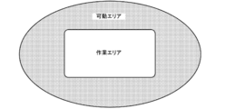
- the work area of the robot is usually set in a range narrower than the movable area (movement limit area) of the robot in order to ensure the proper operation of the robot. In this case, it is difficult for the operator to properly teach directly unless he / she can grasp the working area of the robot.
- the main purpose of this disclosure is to have the operator properly execute the teaching directly.
- This disclosure has taken the following measures to achieve the above-mentioned main purpose.
- the robot control device of the present disclosure is A robot control device that controls a robot A position sensor that detects the position of the robot and A force sensor that detects the external force applied to the robot by the operation of the operator and the direction of the external force, and When an external force is applied to the robot, when the position of the robot is within the first area set in the work area of the robot, an assist control for generating an assist force in the direction of the external force applied to the robot is performed. When the robot is executed and the position of the robot is in the second area set outside the work area of the robot, the execution of the assist control is stopped, and the position of the robot is outside the first area and the first area. A control device that limits the execution of the assist control when it is in the third area set inside the two areas, and The gist is to prepare.
- the robot control device of the present invention when an external force is applied to the robot by an operator's operation, the direction of the external force applied to the robot when the position of the robot is within the first area set in the work area.
- the assist control for generating the assist force is executed, and when the position of the robot is in the second area set outside the work area of the robot, the execution of the assist control is stopped. Further, the robot control device limits the execution of the assist control when the position of the robot is outside the first area and within the third area set inside the second area. In this way, the robot control device changes the assist force stepwise for each area, so that when the operator operates the robot and directly teaches, the robot is out of the work area or is about to come off. Can be sensuously notified to the operator. As a result, the operator can grasp the work area and properly execute the teaching directly.
- a work area is set in a part of the movable area of the robot, and the work area is set.
- a first area is set in the work area
- a second area is set outside the work area
- a third area is set outside the first area and inside the second area.
- a work area is set in a part of the movable area (movement limit area) of the robot, a first area is set in the work area, and a second area is set outside the work area. Then, the third area is set outside the first area and inside the second area. Then, in the direct teaching method, when an external force is applied to the robot by the operation of the operator, when the position of the robot is within the first area, an assist control for generating an assist force in the direction of the external force applied to the robot is executed. Then, when the position of the robot is in the second area, the execution of the assist control is stopped. Further, the direct teaching method limits the execution of assist control when the position of the robot is within the third area.
- the assist force is changed stepwise for each area, so that the robot goes out of the work area or goes out of the work area when the operator operates the robot to give direct teaching. It is possible to intuitively inform the operator that this will happen. As a result, the operator can grasp the work area and properly execute the teaching directly.
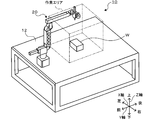
- FIG. 1 is a configuration diagram showing an outline of the configuration of the work robot 10 of the present embodiment.
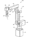
- FIG. 2 is a configuration diagram showing an outline of the configuration of the robot main body 20.
- FIG. 3 is a block diagram showing an electrical connection relationship between the robot body 20 and the control device 80.
- the left-right direction is the X-axis direction
- the front-back direction is the Y-axis direction
- the up-down direction is the Z-axis direction.
- the work robot 10 performs a predetermined work (for example, a transport work for transporting the work W and an inspection work for inspecting the work W) on the work W placed in the work area of the workbench 12. , Assembling work to assemble the work W, etc.).
- the working robot 10 includes a robot main body 20 and a control device 80.
- the robot body 20 includes a 5-axis vertical articulated arm (hereinafter referred to as an arm) 22 in the present embodiment.
- the arm 22 has six links (first to sixth links 31 to 36) and five joints (first to fifth joints 41 to 45) that rotatably or swivelly connect between the links.
- each joint (1st to 5th joints 41 to 45) has motors (servomotors) 51 to 55 for driving the corresponding joints and encoders (servomotors) 51 to 55 for detecting the rotation angle of the corresponding motors.
- Rotary encoders) 61 to 65 are provided.
- the tip link (sixth link 36) of the arm 22 has a force component acting in each of the X-axis, Y-axis, and Z-axis directions as an external force acting on the arm 22 and around each axis.
- a force sensor 24 that detects an acting torque component is attached.
- the control device 80 is configured as a microprocessor centered on a CPU 81, and includes a ROM 82, an HDD 83, a RAM 84, an input / output interface (not shown), and the like in addition to the CPU 81.
- a detection signal from the force sensor 24, a detection signal from the encoders 61 to 65, an input signal from the input device 85, and the like are input to the control device 80 via the input / output interface.
- the control device 80 outputs a control signal to the motors 51 to 55 and the like, an output signal to the output device 86, and the like via the input / output interface.
- the input device 85 is an input device such as a keyboard or a mouse in which an operator performs an input operation.
- the output device 86 is a display device for displaying various information such as a liquid crystal display.
- the CPU 81 of the control device 80 first acquires the target position and the target posture of the tip of the arm 22. Subsequently, the CPU 81 calculates the target angles of the first to fifth joints 41 to 45 for moving the tip of the arm 22 to the target position and the target posture. Then, the CPU 81 drives and controls the corresponding motors 51 to 55 so that the angles of the joints detected by the encoders 61 to 65 match the target angles.
- the target position and posture can be set by the operator holding the tip of the arm 22 by hand and teaching while moving the arm 22 by hand in the work area (direct teaching method).
- the work area is an area in which the arm 22 can be moved appropriately, and is set in a range narrower than the movable area (movement limit area) as shown in FIG. Therefore, if the worker cannot grasp the work area, the arm 22 may be unintentionally removed from the work area, and the worker may not be able to properly teach directly. Therefore, in the work robot 10 of the present embodiment, when the operator operates the arm 22 to directly teach, an assist force is generated in the direction in which the arm 22 is operated to assist the operator's operation. When the arm 22 is about to go out of the work area or comes off, the assist force to be generated is changed to sensuously inform the operator of the fact.
- FIG. 5 is a flowchart showing an example of a control routine executed by the CPU 81 of the control device 80. This routine is executed when the worker directly teaches.
- the CPU 81 of the control device 80 first acquires the rotation angles ⁇ 1 to ⁇ 5 of each joint (first to fifth joints 41 to 45) from the encoders 61 to 65, and attaches to the arm 22 from the force sensor 24.
- the acting external force is acquired as the operating force F and the operating direction with respect to the arm 22 of the operator (S100).
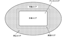
- the CPU 81 calculates the hand position (X, Y, Z), which is the position of the hand (tip) of the arm 22, by forward kinematics based on the rotation angles ⁇ 1 to ⁇ 5 of each joint (S110). Then, in the CPU 81, the hand of the arm 22 is any of the assist area (first area), the stop area (second area), and the deceleration area (third area) based on the calculated hand position (X, Y, Z). It is determined whether or not it is within the area of (S120, S130).
- the assist area is set inside the work area, and the stop area is set outside the work area. Further, the deceleration area is set between the assist area and the stop area. In the present embodiment, as shown in FIG. 6, the deceleration area is set outside the work area so that the boundary between the assist area and the deceleration area coincides with the outer edge of the work area.
- the CPU 81 determines that the hand of the arm 22 is in the assist area (“YES” in S120)
- the CPU 81 sets a target load L, which is a target value of the load applied to the worker's hand when the worker operates the arm 22.
- the CPU 81 sets the target assist force A, which is the target value of the assist force, so that the assist force corresponding to the target load L acts in the operation direction (S200).
- the CPU 81 performs assist control for driving and controlling the motors 51 to 55 so that the set target assist force A is output (S210).
- the operator can operate the arm 22 with a light load in the assist area (inside the work area) by minimizing the load applied to the operator's hand. Direct teaching can be performed smoothly.
- the CPU 81 determines whether or not the operation direction of the arm 22 by the operator is the assist area direction. (S150). When the CPU 81 determines that the operation direction of the arm 22 is not the assist area direction, the CPU 81 sets the target load L to the maximum value Lmax (S160). Then, the CPU 81 sets the target assist force A so that the assist force corresponding to the target load L acts in the operation direction, and drives and controls the motors 51 to 55 (S200, S210). In the present embodiment, when the target load L is the maximum value Lmax, a value 0 is set for the target assist force A.
- the assist force does not act on the hand of the arm 22, it can be said that the execution of the assist control is stopped.
- the target load L is the maximum value Lmax
- a negative value may be set for the target assist force A.
- the resistance force acts in the direction opposite to the operating direction of the arm 22 by the operator. In this way, when the hand of the arm 22 is in the stop area, the worker almost always operates the arm 22 in the stop area (outside the work area) by maximizing the load applied to the worker's hand. It becomes impossible.
- the CPU 81 determines whether or not the operation direction of the arm 22 by the operator is the assist area direction. (S170).
- the CPU 81 sets a target load setting map for setting the target load L (S180). Then, the CPU 81 sets the target load L using the set target load setting map (S190), sets the target assist force A so that the assist force corresponding to the target load L acts, and sets each of the motors 51 to 55. Is driven and controlled (S200, S210). In this case, since the target load L is set to a value larger than the above-mentioned minimum value Lmin and smaller than the above-mentioned maximum value Lmax, it can be said that the execution of the assist control is restricted.
- step S180 is performed by setting one map selected by the operator by operating the input device 85 from the plurality of target load setting maps stored in advance.
- 7 to 9 are explanatory views showing an example of a target load setting map.
- the map of FIG. 7 is defined so that the target load L changes linearly with respect to the change in the hand position of the arm 22.
- the map of FIG. 8 is defined so that the target load L changes in a convex curve shape in response to a change in the hand position of the arm 22.
- the map of FIG. 9 is defined so that the target load L changes in a concave curve shape in response to a change in the hand position of the arm 22. Further, in each of the maps of FIGS.
- the target load L is set to increase as the hand of the arm 22 approaches the stop area.
- the load applied to the worker's hand gradually increases as the hand of the arm 22 approaches the stop area, so that the worker can work with the hand of the arm 22. It becomes possible to recognize that it is out of the area.
- the load changes in proportion to the change in the position of the arm 22, so that the operator can change the hand of the arm 22 from the magnitude of the load applied to the hand. It becomes easier to recognize how far you are out of the work area. Further, when the operator selects the map of FIG.
- the load changes sharply immediately after the hand of the arm 22 goes out of the assist area, so that the operator changes the load applied to the hand of the arm 22. It becomes easier to recognize that the hand has left the assist area. Further, when the worker selects the map of FIG. 9, the load changes sharply when the hand of the arm 22 approaches the stop area, so that the worker changes the load applied to the hand of the arm 22. It becomes easier to recognize that the hand has approached the stop area. Note that some of the plurality of target load setting maps described above may be omitted.
- the CPU 81 determines in step S150 or S170 that the operation direction of the arm 22 is the assist area direction, the CPU 81 sets the minimum value Lmin for the target load L as in the case where the hand of the arm 22 is in the assist area ( S140), the target assist force A is set so that the assist force corresponding to the target load L acts, and the motors 51 to 55 are driven and controlled (S200, S210).
- the motors 51 to 55 are driven and controlled (S200, S210).
- the CPU 81 drives and controls each of the motors 51 to 55 according to the target assist force A in this way, it determines whether or not the direct teaching is completed (S220). When the CPU 81 determines that the direct teaching is not completed, it returns to S100 and repeats the process, and when it is determined that the direct teaching is completed, the CPU 81 ends the control routine.
- the arm 22 of this embodiment corresponds to a robot
- the encoders 61 to 65 correspond to a position sensor
- the force sensor 24 corresponds to a force sensor
- the control device 80 corresponds to a control device.
- the deceleration area is set outside the work area.
- the deceleration area may be set within the work area.
- the deceleration area may be set so as to straddle the boundary of the work area. This makes it possible for the operator to recognize in advance that the hand of the arm 22 is likely to go out of the work area.
- the control device 80 determines whether the arm 22 is in the assist area, the stop area, or the deceleration area based on the hand (tip) of the arm 22. However, the control device 80 determines in which area the arm 22 is located based on the tool attached to the hand (tip) of the arm 22, and what kind of location is the reference position of the arm 22 used for the determination. It doesn't matter.
- the control device 80 sets the target load L so that when the hand of the arm 22 is in the deceleration area, the target load L gradually increases from the minimum value Lmin to the maximum value Lmax as it approaches the stop area. I made it.
- the control device 80 may set the target load L to a constant value larger than the minimum value Lmin and smaller than the maximum value Lmax when the hand of the arm 22 is in the deceleration area.
- the control device 80 is one map selected by the operator from a plurality of target load setting maps having different slopes of changes in the target load L with respect to changes in the hand position of the arm 22.
- the target load L may be set using.
- the working robot 10 is configured as a vertical articulated robot, but the robot 10 is not limited to this, and may be configured as a horizontal articulated robot, a parallel link robot, or the like.
- the robot control device of the present disclosure is a robot control device that controls a robot, and is a position sensor that detects the position of the robot and a direction of an external force and an external force applied to the robot by an operator's operation.
- the robot assists in the direction of the external force applied to the robot when the position of the robot is within the first area set in the work area of the robot.
- Assist control for generating force is executed, and when the position of the robot is in the second area set outside the work area of the robot, the execution of the assist control is stopped, and the position of the robot is the first area. It is a gist to include a control device that limits the execution of the assist control when it is in a third area set outside the second area and inside the second area.
- the robot control device of the present invention when an external force is applied to the robot by an operator's operation, the direction of the external force applied to the robot when the position of the robot is within the first area set in the work area.
- the assist control for generating the assist force is executed, and when the position of the robot is in the second area set outside the work area of the robot, the execution of the assist control is stopped. Further, the robot control device limits the execution of the assist control when the position of the robot is outside the first area and within the third area set inside the second area. In this way, the robot control device changes the assist force stepwise for each area, so that when the operator operates the robot and directly teaches, the robot is out of the work area or is about to come off. Can be sensuously notified to the operator. As a result, the operator can grasp the work area and properly execute the teaching directly.
- At least a part of the third area may be set in the work area. In this way, the operator can sense in advance that the robot is about to leave the work area.
- the control device of the present disclosure when the position of the robot is in the third area, the control device is in a direction in which the direction of the external force applied to the robot approaches the second area.
- the robot may be controlled so that the assist force is not suppressed when the assist force is suppressed and the direction of the external force applied to the robot is a direction approaching the first area. In this way, the operator can intuitively know that the robot has approached the second area (outside the work area), and can easily return the robot to the first area (inside the work area).
- the control device when the position of the robot is in the third area, the load on the operation of the robot by the operator increases as the position of the robot approaches the second area.
- the robot may be controlled so as to be large, and the robot may be controlled so that the load is maximized when the position of the robot is within the second area. In this way, the operator can intuitively know how much time the robot has before reaching the second area (outside the work area).
- the control device may control the robot so that the load changes linearly with respect to the change in the position of the robot when the position of the robot is in the third area. .. In this way, the operator can easily recognize the position of the robot in the second area from the magnitude of the load.
- control device may control the robot so that when the position of the robot is within the third area, the load changes in a convex curve with respect to the change in the position of the robot. .. In this way, the operator can easily recognize that the robot has moved out of the first area (inside the work area) due to the change in load.
- control device may control the robot so that when the position of the robot is within the third area, the load changes in a concave curve with respect to a change in the position of the robot. .. In this way, the operator can easily recognize that the robot has approached the second area due to the change in load.
- control device has a plurality of modes as the mode of the change of the load with respect to the change of the position of the robot, and the control device selects from the plurality of modes when the position of the robot is within the third area.
- the robot may be controlled so that the load changes in response to a change in the position of the robot. In this way, the load can be adjusted according to the preference of the operator.
- the direct teaching method of the present disclosure is a robot direct teaching method, in which a work area is set in a part of the movable area of the robot, a first area is set in the work area, and the outside of the work area. A second area is set in the robot, and a third area is set outside the first area and inside the second area.
- the robot When an external force is applied to the robot by an operator's operation, the robot When the position is in the first area, the assist control for generating the assist force in the direction of the external force applied to the robot is executed, and when the position of the robot is in the second area, the assist control is executed.
- the gist is to limit the execution of the assist control when the robot is stopped and the position of the robot is within the third area.
- a work area is set in a part of the movable area (movement limit area) of the robot, a first area is set in the work area, and a second area is set outside the work area. Then, the third area is set outside the first area and inside the second area. Then, in the direct teaching method, when an external force is applied to the robot by the operation of the operator, when the position of the robot is within the first area, an assist control for generating an assist force in the direction of the external force applied to the robot is executed. Then, when the position of the robot is in the second area, the execution of the assist control is stopped. Further, the direct teaching method limits the execution of assist control when the position of the robot is within the third area.
- the assist force is changed stepwise for each area, so that the robot goes out of the work area or goes out of the work area when the operator operates the robot to give direct teaching. It is possible to intuitively inform the operator that this will happen. As a result, the operator can grasp the work area and properly execute the teaching directly.
- This disclosure can be used in the robot manufacturing industry and the like.
Landscapes
- Engineering & Computer Science (AREA)
- Robotics (AREA)
- Mechanical Engineering (AREA)
- Human Computer Interaction (AREA)
- Physics & Mathematics (AREA)
- General Physics & Mathematics (AREA)
- Automation & Control Theory (AREA)
- Manufacturing & Machinery (AREA)
- Manipulator (AREA)
Priority Applications (3)
| Application Number | Priority Date | Filing Date | Title |
|---|---|---|---|
| PCT/JP2019/038577 WO2021064809A1 (ja) | 2019-09-30 | 2019-09-30 | ロボット制御装置およびロボットの直接教示方法 |
| US17/763,015 US12138811B2 (en) | 2019-09-30 | 2019-09-30 | Robot control device and direct teaching method for robot |
| JP2021550766A JPWO2021064809A1 (https=) | 2019-09-30 | 2019-09-30 |
Applications Claiming Priority (1)
| Application Number | Priority Date | Filing Date | Title |
|---|---|---|---|
| PCT/JP2019/038577 WO2021064809A1 (ja) | 2019-09-30 | 2019-09-30 | ロボット制御装置およびロボットの直接教示方法 |
Publications (1)
| Publication Number | Publication Date |
|---|---|
| WO2021064809A1 true WO2021064809A1 (ja) | 2021-04-08 |
Family
ID=75337830
Family Applications (1)
| Application Number | Title | Priority Date | Filing Date |
|---|---|---|---|
| PCT/JP2019/038577 Ceased WO2021064809A1 (ja) | 2019-09-30 | 2019-09-30 | ロボット制御装置およびロボットの直接教示方法 |
Country Status (3)
| Country | Link |
|---|---|
| US (1) | US12138811B2 (https=) |
| JP (1) | JPWO2021064809A1 (https=) |
| WO (1) | WO2021064809A1 (https=) |
Cited By (1)
| Publication number | Priority date | Publication date | Assignee | Title |
|---|---|---|---|---|
| EP4417135A4 (en) * | 2021-10-13 | 2024-12-11 | Fuji Corporation | ULTRASONIC DIAGNOSTIC SYSTEM AND ASSOCIATED MONITORING METHOD |
Families Citing this family (1)
| Publication number | Priority date | Publication date | Assignee | Title |
|---|---|---|---|---|
| WO2021263268A1 (en) * | 2020-06-22 | 2021-12-30 | H.B. Fuller Company | Packaging testing device |
Citations (5)
| Publication number | Priority date | Publication date | Assignee | Title |
|---|---|---|---|---|
| JPS63260779A (ja) * | 1987-04-20 | 1988-10-27 | 富士通株式会社 | 直接教示制御方式 |
| JPH09141580A (ja) * | 1995-11-22 | 1997-06-03 | Yaskawa Electric Corp | 直接教示ロボットの動作範囲制限装置 |
| JPH11347983A (ja) * | 1998-06-11 | 1999-12-21 | Meidensha Corp | マニプレータの動作制限装置 |
| JP2011245614A (ja) * | 2010-05-26 | 2011-12-08 | GM Global Technology Operations LLC | 速度制御ロボット機構におけるワークスペース制限の応用 |
| JP2014217913A (ja) * | 2013-05-08 | 2014-11-20 | パナソニック株式会社 | パラレルリンクロボットの動作教示方法およびパラレルリンクロボット |
Family Cites Families (5)
| Publication number | Priority date | Publication date | Assignee | Title |
|---|---|---|---|---|
| EP2258521B1 (en) * | 2008-02-28 | 2015-08-19 | Panasonic Intellectual Property Management Co., Ltd. | Control apparatus and control method for a robot arm, robot, control program for a robot arm, and electronic integrated circuit for controlling a robot arm |
| JP6520478B2 (ja) * | 2015-06-30 | 2019-05-29 | 株式会社デンソーウェーブ | ロボットアームの操作システム |
| US10562191B2 (en) * | 2015-12-29 | 2020-02-18 | Robomotive Laboratories LLC | Method of controlling devices with sensation of applied force |
| JP2017202554A (ja) | 2016-05-12 | 2017-11-16 | 株式会社リコー | マニピュレータ装置の制御装置、マニピュレータ装置の制御方法及びマニピュレータ装置の制御プログラム |
| JP7263724B2 (ja) * | 2018-09-27 | 2023-04-25 | 株式会社デンソーウェーブ | ロボットの制御方法 |
-
2019
- 2019-09-30 US US17/763,015 patent/US12138811B2/en active Active
- 2019-09-30 WO PCT/JP2019/038577 patent/WO2021064809A1/ja not_active Ceased
- 2019-09-30 JP JP2021550766A patent/JPWO2021064809A1/ja active Pending
Patent Citations (5)
| Publication number | Priority date | Publication date | Assignee | Title |
|---|---|---|---|---|
| JPS63260779A (ja) * | 1987-04-20 | 1988-10-27 | 富士通株式会社 | 直接教示制御方式 |
| JPH09141580A (ja) * | 1995-11-22 | 1997-06-03 | Yaskawa Electric Corp | 直接教示ロボットの動作範囲制限装置 |
| JPH11347983A (ja) * | 1998-06-11 | 1999-12-21 | Meidensha Corp | マニプレータの動作制限装置 |
| JP2011245614A (ja) * | 2010-05-26 | 2011-12-08 | GM Global Technology Operations LLC | 速度制御ロボット機構におけるワークスペース制限の応用 |
| JP2014217913A (ja) * | 2013-05-08 | 2014-11-20 | パナソニック株式会社 | パラレルリンクロボットの動作教示方法およびパラレルリンクロボット |
Cited By (1)
| Publication number | Priority date | Publication date | Assignee | Title |
|---|---|---|---|---|
| EP4417135A4 (en) * | 2021-10-13 | 2024-12-11 | Fuji Corporation | ULTRASONIC DIAGNOSTIC SYSTEM AND ASSOCIATED MONITORING METHOD |
Also Published As
| Publication number | Publication date |
|---|---|
| US12138811B2 (en) | 2024-11-12 |
| JPWO2021064809A1 (https=) | 2021-04-08 |
| US20220347852A1 (en) | 2022-11-03 |
Similar Documents
| Publication | Publication Date | Title |
|---|---|---|
| US9073211B2 (en) | Control system and teaching method for seven-axis articulated robot | |
| US10751874B2 (en) | Method of teaching robot and robotic arm control device | |
| JP6484265B2 (ja) | 学習制御機能を備えたロボットシステム及び学習制御方法 | |
| JP6450960B2 (ja) | ロボット、ロボットシステム及び教示方法 | |
| JP5849451B2 (ja) | ロボットの故障検出方法、制御装置およびロボット | |
| CN111975746A (zh) | 机器人的控制方法 | |
| CN106493711B (zh) | 控制装置、机器人以及机器人系统 | |
| CN104044131A (zh) | 机器人系统、校正方法及被加工物制造方法 | |
| US11745339B2 (en) | Horizontal articulated robot | |
| US12076857B2 (en) | Method for precise, intuitive positioning of robotic welding machine | |
| US11833687B2 (en) | Robot apparatus, control method for the robot apparatus, assembly method using the robot apparatus, and recording medium | |
| CN105312885A (zh) | 齿轮组装系统及齿轮组装方法 | |
| CN212421307U (zh) | 一种提升安全控制性能的工业机器人 | |
| JP2011253300A (ja) | ロボット制御システム | |
| WO2021064809A1 (ja) | ロボット制御装置およびロボットの直接教示方法 | |
| JP2010023184A (ja) | 作業座標系の設定方法及び作業座標系の異常検出方法 | |
| JP2009000799A (ja) | 作業管理システム | |
| US20180154520A1 (en) | Control device, robot, and robot system | |
| JP6697544B2 (ja) | 最適化装置及びそれを備えた垂直型多関節ロボット | |
| KR20130000496A (ko) | 가속도센서와 자이로센서를 구비한 로봇 교시장치와 이를 이용한 로봇제어방법 | |
| JP2019155523A (ja) | ロボット制御装置、ロボット制御方法、ロボット制御装置を用いた物品の組立方法、プログラム及び記録媒体 | |
| CN113771026B (zh) | 一种提升安全控制性能的工业机器人及其控制方法 | |
| WO2022210186A1 (ja) | ロボットの位置および姿勢を制御するパラメータを算出する制御装置 | |
| JP7846206B2 (ja) | 作業ロボットシステム | |
| US12109702B2 (en) | Method of adjusting force control parameter, robot system, and force control parameter adjustment program |
Legal Events
| Date | Code | Title | Description |
|---|---|---|---|
| 121 | Ep: the epo has been informed by wipo that ep was designated in this application |
Ref document number: 19948123 Country of ref document: EP Kind code of ref document: A1 |
|
| ENP | Entry into the national phase |
Ref document number: 2021550766 Country of ref document: JP Kind code of ref document: A |
|
| NENP | Non-entry into the national phase |
Ref country code: DE |
|
| 122 | Ep: pct application non-entry in european phase |
Ref document number: 19948123 Country of ref document: EP Kind code of ref document: A1 |