WO2021064805A1 - Saddle-ridden vehicle, method for controlling saddle-ridden vehicle, and program - Google Patents
Saddle-ridden vehicle, method for controlling saddle-ridden vehicle, and program Download PDFInfo
- Publication number
- WO2021064805A1 WO2021064805A1 PCT/JP2019/038562 JP2019038562W WO2021064805A1 WO 2021064805 A1 WO2021064805 A1 WO 2021064805A1 JP 2019038562 W JP2019038562 W JP 2019038562W WO 2021064805 A1 WO2021064805 A1 WO 2021064805A1
- Authority
- WO
- WIPO (PCT)
- Prior art keywords
- saddle
- vehicle
- detection
- region
- type vehicle
- Prior art date
Links
Images


Classifications
-
- B—PERFORMING OPERATIONS; TRANSPORTING
- B62—LAND VEHICLES FOR TRAVELLING OTHERWISE THAN ON RAILS
- B62J—CYCLE SADDLES OR SEATS; AUXILIARY DEVICES OR ACCESSORIES SPECIALLY ADAPTED TO CYCLES AND NOT OTHERWISE PROVIDED FOR, e.g. ARTICLE CARRIERS OR CYCLE PROTECTORS
- B62J45/00—Electrical equipment arrangements specially adapted for use as accessories on cycles, not otherwise provided for
- B62J45/40—Sensor arrangements; Mounting thereof
- B62J45/41—Sensor arrangements; Mounting thereof characterised by the type of sensor
-
- B—PERFORMING OPERATIONS; TRANSPORTING
- B62—LAND VEHICLES FOR TRAVELLING OTHERWISE THAN ON RAILS
- B62J—CYCLE SADDLES OR SEATS; AUXILIARY DEVICES OR ACCESSORIES SPECIALLY ADAPTED TO CYCLES AND NOT OTHERWISE PROVIDED FOR, e.g. ARTICLE CARRIERS OR CYCLE PROTECTORS
- B62J27/00—Safety equipment
-
- B—PERFORMING OPERATIONS; TRANSPORTING
- B62—LAND VEHICLES FOR TRAVELLING OTHERWISE THAN ON RAILS
- B62J—CYCLE SADDLES OR SEATS; AUXILIARY DEVICES OR ACCESSORIES SPECIALLY ADAPTED TO CYCLES AND NOT OTHERWISE PROVIDED FOR, e.g. ARTICLE CARRIERS OR CYCLE PROTECTORS
- B62J45/00—Electrical equipment arrangements specially adapted for use as accessories on cycles, not otherwise provided for
- B62J45/40—Sensor arrangements; Mounting thereof
- B62J45/41—Sensor arrangements; Mounting thereof characterised by the type of sensor
- B62J45/412—Speed sensors
-
- B—PERFORMING OPERATIONS; TRANSPORTING
- B62—LAND VEHICLES FOR TRAVELLING OTHERWISE THAN ON RAILS
- B62J—CYCLE SADDLES OR SEATS; AUXILIARY DEVICES OR ACCESSORIES SPECIALLY ADAPTED TO CYCLES AND NOT OTHERWISE PROVIDED FOR, e.g. ARTICLE CARRIERS OR CYCLE PROTECTORS
- B62J45/00—Electrical equipment arrangements specially adapted for use as accessories on cycles, not otherwise provided for
- B62J45/40—Sensor arrangements; Mounting thereof
- B62J45/41—Sensor arrangements; Mounting thereof characterised by the type of sensor
- B62J45/415—Inclination sensors
- B62J45/4151—Inclination sensors for sensing lateral inclination of the cycle
-
- B—PERFORMING OPERATIONS; TRANSPORTING
- B62—LAND VEHICLES FOR TRAVELLING OTHERWISE THAN ON RAILS
- B62J—CYCLE SADDLES OR SEATS; AUXILIARY DEVICES OR ACCESSORIES SPECIALLY ADAPTED TO CYCLES AND NOT OTHERWISE PROVIDED FOR, e.g. ARTICLE CARRIERS OR CYCLE PROTECTORS
- B62J50/00—Arrangements specially adapted for use on cycles not provided for in main groups B62J1/00 - B62J45/00
- B62J50/20—Information-providing devices
- B62J50/21—Information-providing devices intended to provide information to rider or passenger
- B62J50/22—Information-providing devices intended to provide information to rider or passenger electronic, e.g. displays
-
- G—PHYSICS
- G01—MEASURING; TESTING
- G01S—RADIO DIRECTION-FINDING; RADIO NAVIGATION; DETERMINING DISTANCE OR VELOCITY BY USE OF RADIO WAVES; LOCATING OR PRESENCE-DETECTING BY USE OF THE REFLECTION OR RERADIATION OF RADIO WAVES; ANALOGOUS ARRANGEMENTS USING OTHER WAVES
- G01S13/00—Systems using the reflection or reradiation of radio waves, e.g. radar systems; Analogous systems using reflection or reradiation of waves whose nature or wavelength is irrelevant or unspecified
- G01S13/88—Radar or analogous systems specially adapted for specific applications
- G01S13/93—Radar or analogous systems specially adapted for specific applications for anti-collision purposes
- G01S13/931—Radar or analogous systems specially adapted for specific applications for anti-collision purposes of land vehicles
- G01S2013/9315—Monitoring blind spots
-
- G—PHYSICS
- G01—MEASURING; TESTING
- G01S—RADIO DIRECTION-FINDING; RADIO NAVIGATION; DETERMINING DISTANCE OR VELOCITY BY USE OF RADIO WAVES; LOCATING OR PRESENCE-DETECTING BY USE OF THE REFLECTION OR RERADIATION OF RADIO WAVES; ANALOGOUS ARRANGEMENTS USING OTHER WAVES
- G01S13/00—Systems using the reflection or reradiation of radio waves, e.g. radar systems; Analogous systems using reflection or reradiation of waves whose nature or wavelength is irrelevant or unspecified
- G01S13/88—Radar or analogous systems specially adapted for specific applications
- G01S13/93—Radar or analogous systems specially adapted for specific applications for anti-collision purposes
- G01S13/931—Radar or analogous systems specially adapted for specific applications for anti-collision purposes of land vehicles
- G01S2013/9322—Radar or analogous systems specially adapted for specific applications for anti-collision purposes of land vehicles using additional data, e.g. driver condition, road state or weather data
-
- G—PHYSICS
- G01—MEASURING; TESTING
- G01S—RADIO DIRECTION-FINDING; RADIO NAVIGATION; DETERMINING DISTANCE OR VELOCITY BY USE OF RADIO WAVES; LOCATING OR PRESENCE-DETECTING BY USE OF THE REFLECTION OR RERADIATION OF RADIO WAVES; ANALOGOUS ARRANGEMENTS USING OTHER WAVES
- G01S13/00—Systems using the reflection or reradiation of radio waves, e.g. radar systems; Analogous systems using reflection or reradiation of waves whose nature or wavelength is irrelevant or unspecified
- G01S13/88—Radar or analogous systems specially adapted for specific applications
- G01S13/93—Radar or analogous systems specially adapted for specific applications for anti-collision purposes
- G01S13/931—Radar or analogous systems specially adapted for specific applications for anti-collision purposes of land vehicles
- G01S2013/9327—Sensor installation details
- G01S2013/93272—Sensor installation details in the back of the vehicles
-
- G—PHYSICS
- G01—MEASURING; TESTING
- G01S—RADIO DIRECTION-FINDING; RADIO NAVIGATION; DETERMINING DISTANCE OR VELOCITY BY USE OF RADIO WAVES; LOCATING OR PRESENCE-DETECTING BY USE OF THE REFLECTION OR RERADIATION OF RADIO WAVES; ANALOGOUS ARRANGEMENTS USING OTHER WAVES
- G01S13/00—Systems using the reflection or reradiation of radio waves, e.g. radar systems; Analogous systems using reflection or reradiation of waves whose nature or wavelength is irrelevant or unspecified
- G01S13/88—Radar or analogous systems specially adapted for specific applications
- G01S13/93—Radar or analogous systems specially adapted for specific applications for anti-collision purposes
- G01S13/931—Radar or analogous systems specially adapted for specific applications for anti-collision purposes of land vehicles
- G01S2013/9327—Sensor installation details
- G01S2013/93274—Sensor installation details on the side of the vehicles
Definitions
- the present invention relates to a saddle-mounted vehicle, a control method and a program for a saddle-mounted vehicle.
- Patent Document 1 discloses a technique of detecting the situation behind the own vehicle and notifying the driver of the existence of the other vehicle by blinking a lamp or the like when another vehicle is detected in the rear detection area. ing.
- Patent Document 1 since the setting of the rear detection area is fixed during straight-ahead driving and turning, the driver can visually recognize the rear detection area depending on the turning direction and turning radius of the vehicle. A difficult area (blind area) may occur.
- An object of the present invention is to provide a technique capable of changing the setting of the detection area in the rear detection unit based on the turning direction and the turning radius of the saddle-type vehicle in view of the problems of the prior art.
- the saddle-mounted vehicle has a rear detection means for detecting an object in a detection region behind the vehicle and a notification for notifying the driver when the object is detected by the rear detection means.
- a saddle-type vehicle having means and An acquisition means for acquiring the traveling information of the saddle-type vehicle, and A specific means for specifying the turning direction and turning radius of the saddle-type vehicle based on the traveling information, and It is characterized by including a changing means for changing the setting of the detection area when traveling straight in the rear detecting means based on the turning direction and the turning radius.
- the method for controlling a saddle-type vehicle is to the rear detecting means for detecting an object in the detection region behind the vehicle and to the driver when the object is detected by the rear detecting means. It is a control method of a saddle-type vehicle having a notification means for performing notification.
- the acquisition process of acquiring the traveling information of the saddle-type vehicle and the acquisition means A specific step in which the specific means specifies the turning direction and turning radius of the saddle-type vehicle based on the traveling information.
- the changing means includes a changing step of changing the setting of the detection area when traveling straight in the rear detecting means based on the turning direction and the turning radius.
- the present invention it is possible to change the setting of the detection area in the rear detection unit based on the turning direction and turning radius of the saddle-type vehicle.
- the accompanying drawings are included in the specification and are used to form a part thereof, show embodiments of the present invention, and explain the principles of the present invention together with the description thereof.
- the block diagram which shows the functional structure of the detection area control device.
- the figure explaining the process flow of the detection area control apparatus The figure which illustrates the table of 2nd Embodiment.
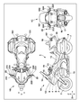
- FIG. 1 is a diagram illustrating a configuration of a saddle-mounted vehicle 1 according to an embodiment of the present invention.
- 1A of FIG. 1 is a left side view of the saddle-mounted vehicle 1
- 1B of FIG. 1 is a top view of the saddle-mounted vehicle 1
- 1C of FIG. 1 is a rear view of the saddle-mounted vehicle 1.
- the X direction indicates the front-rear direction of the saddle-mounted vehicle 1
- the Y direction indicates the vehicle width direction of the saddle-mounted vehicle 1.
- the Z direction indicates the vertical direction of the saddle-mounted vehicle 1.
- the front wheels 2 are pivotally supported by the lower ends of a pair of left and right front forks 3.
- the upper parts of the left and right front forks 3 are pivotally supported by the head pipe 6 at the front end of the vehicle body frame 5 via the steering stem 4.
- the saddle-mounted vehicle 1 is steered by the handlebar 19 attached to the head pipe 6. Handle grips gripped by the driver are provided at the left and right ends of the handlebar 19. Further, the handlebar 19 is provided with a brake lever, a clutch lever, and the like adjacent to the left and right handle grips (not shown).
- the rear wheel 7 of the saddle-mounted vehicle 1 is pivotally supported by the rear end of the arm 8 extending forward and backward on the lower rear side of the vehicle body.
- the front end portion of the arm 8 is pivotally supported so as to be swingable up and down at the front-rear intermediate portion of the vehicle body frame 5.
- the engine (internal combustion engine) 10 which is the prime mover of the saddle-mounted vehicle 1, is mounted on the body frame 5.
- a fuel tank 11 is arranged above the engine 10, and a seat 12 on which the driver of the motorcycle 1 is seated is arranged behind the fuel tank 11.
- a trunk case 18 for storing articles is arranged at the rear of the seat 12 on which the driver sits.
- a front cowl 13 supported by a vehicle body frame 5 is mounted on the front portion of the vehicle body.
- a screen 14 is provided on the upper front side of the front cowl 13.
- the meter panel 15 is arranged inside the front cowl 13 and the screen 14.
- the meter panel 15 displays various information such as vehicle speed, engine speed, and other vehicle conditions.
- a tail winker 16 and a tail light 17 are provided at the rear portion of the saddle-mounted vehicle 1.
- radars 101 and 102 are arranged as rear detection units 100 for detecting an object in the detection region behind the vehicle.
- the radars 101 and 102 are arranged at the left and right rear positions of the saddle-mounted vehicle 1, respectively.
- the radar 101 detects an object in the detection region on the left rear side of the saddle-mounted vehicle 1.
- the radar 102 detects an object in the detection region on the right rear side of the saddle-mounted vehicle 1.
- the arrangement of the rear detection unit 100 shown in FIG. 1 is an example, and a single radar may be arranged in the rear center of the saddle-mounted vehicle 1, or two radars may be arranged in the left and right rear. , One radar may be placed in the rear center.
- the type of sensor in the rear detection unit 100 may be, for example, a lidar in addition to the radar.
- the rear detection unit 100 is arranged in the trunk case 18, but the arrangement of the rear detection unit 100 is not limited to this position.
- the inside of the saddle back 20 of the saddle-mounted vehicle 1 can also be a location where the rear detection unit 100 is arranged.
- Left and right mirror units 22 are provided in the vehicle width direction (y direction) of the saddle-mounted vehicle 1.
- the left and right mirror units 22 include a mirror housing 222, side mirrors (mirror surface portions) 223, and a notification display unit 224.
- the mirror housing 222 is a hollow body having an opening on the rear side, and a side mirror (mirror surface portion) 223 is attached to the mirror housing 222 so as to close the opening. The driver can visually recognize the left and right rear by the side mirror 223.
- the saddle-mounted vehicle 1 of the present embodiment has a notification unit that notifies the driver when an object is detected by the rear detection unit 100.
- the notification display unit 224 of the mirror unit 22 functions as a notification unit that notifies the driver.
- the notification display unit 224 is a light emitting device including a light emitting element such as an LED, a substrate that supports the light emitting element, and a cover lens or the like that covers the front surface of the notification display unit 224. By forming an opening in a part of the side mirror 223 and arranging the notification display unit 224 in the opening, the notification display unit 224 can be provided in the mirror unit 22.
- the arrangement of the notification display unit 224 shown in FIG. 1 is an example, and the arrangement of the notification display unit 224 is not limited to this position.
- the meter panel 15 can also be a location for the notification display unit 224.
- FIG. 2 is a block diagram showing a functional configuration of the detection area control device 200 according to the present embodiment.
- the saddle-mounted vehicle 1 is provided with a rear detection unit 100, a traveling information detection unit 150, and a detection area control device 200.
- the traveling information detection unit 150 detects traveling information (bank angle, vehicle speed, yaw rate, steering angle) indicating the traveling state of the saddle-mounted vehicle 1.
- the detection area control device 200 can change the setting of the detection area in the rear detection unit 100 based on the travel information indicating the traveling state of the saddle-mounted vehicle 1.
- the detection area control device 200 includes an interface unit 201 (IF unit), a specific unit 202, a change unit 203, a traveling area determination unit 204, a storage unit 205 (ROM205a, RAM205b), and a notification control unit 206.
- the specific unit 202, the change unit 203, and the traveling area determination unit 204 which are functional configurations for performing calculation and determination processing, are read from, for example, one or a plurality of CPUs (central processing units) or a storage unit 205.
- the functions of each part are configured using the program.
- the functional configuration of each part may be configured by an integrated circuit or the like as long as it fulfills the same function.
- the interface unit 201 functions as an interface between the rear detection unit 100, the traveling information detection unit 150, and the notification display unit 224, and the interface unit 201 is subjected to, for example, data communication by a predetermined communication protocol.
- a predetermined communication protocol Includes communication interfaces that allow.
- the communication protocol includes, for example, K-Line communication, CAN communication, serial communication, and the like.
- the interface unit 201 can acquire travel information (bank angle, vehicle speed, yaw rate, steering angle) indicating the travel state of the saddle-mounted vehicle 1 detected by the travel information detection unit 150.
- the traveling information detection unit 150 can detect traveling information indicating the traveling state of the saddle-mounted vehicle 1, and the traveling information detecting unit 150 can detect, for example, a plurality of types of traveling information mounted on the saddle-mounted vehicle 1. Sensors (eg, bank angle sensor 151, vehicle speed sensor 152, yaw rate sensor 153, steering angle sensor 154, etc.) are included.
- the bank angle sensor 151 is a sensor that detects the inclination angle (bank angle ⁇ : FIG. 3) of the saddle-mounted vehicle 1. It is also possible to use a G sensor instead of the bank angle sensor 151.
- the G sensor (accelerometer) is a sensor that measures the acceleration (speed change rate) of the saddle-mounted vehicle 1 and can measure the acceleration in the three axes (X-axis, Y-axis, and Z-axis). is there. For example, as shown in FIG. 3, the inclination angle of the saddle-mounted vehicle 1 can be detected based on the measured value in the Y direction of the G sensor.
- the vehicle speed sensor 152 is a sensor that detects the traveling speed of the saddle-mounted vehicle 1, and for example, detects the rotation speed (speed) according to the number of rotations of the wheels of the saddle-mounted vehicle 1. Further, the yaw rate sensor 153 detects the yaw rate (rotation angular velocity) of the saddle-mounted vehicle 1. The steering angle sensor 154 detects the steering angle of the handlebar 19 of the saddle-mounted vehicle 1. The bank angle sensor 151, the vehicle speed sensor 152, the yaw rate sensor 153, and the steering angle sensor 154 repeatedly execute detection when the ignition of the saddle-mounted vehicle 1 is turned on.
- the specific unit 202 describes the turning direction and turning radius of the saddle-mounted vehicle 1 based on the traveling information (yaw rate, steering angle, bank angle, vehicle speed) of the saddle-mounted vehicle 1 acquired by the interface unit 201 (IF unit). To identify.
- the identification unit 202 specifies the turning direction based on, for example, the yaw rate or the steering angle in the traveling information. Further, the specifying unit 202 specifies the turning radius in the turning direction based on, for example, the bank angle and the vehicle speed in the traveling information.
- FIG. 3 is a diagram for explaining an example of calculation for obtaining the turning radius.
- the gravitational acceleration is g
- the bank angle (tilt angle) of the saddle-type vehicle 1 is ⁇ .
- the specific unit 202 can acquire the turning radius by sequentially executing arithmetic processing based on this relational expression in the traveling path.
- the specific unit 202 can acquire the bank angle ⁇ as the detection result of the bank angle sensor 151 and the vehicle speed V as the detection result of the vehicle speed sensor 152, and the specific unit 202 can acquire the bank angle ⁇ and the vehicle speed V as the detection result of the vehicle speed sensor 152.
- the turning radius r is specified by using the detection results of the bank angle sensor 151 and the vehicle speed sensor 152, but the calculation based on the above relational expression is an example, and is not limited to this example. Absent. For example, it is also possible to specify the turning radius r by using the detection result of the bank angle sensor 151 (bank angle (tilt angle): ⁇ ) and the detection result of the yaw rate sensor 153 (rotation angular velocity ⁇ ).
- the changing unit 203 changes the setting of the detection area when traveling straight in the rear detecting unit 100 based on the turning direction and turning radius.
- the changing unit 203 changes the shape of the detection area set when traveling straight ahead in the detection area of the rear detecting unit 100 to a curved region having a curved shape according to the turning direction and the turning radius.
- the specific unit 202 described above specifies the turning radius in the turning direction acquired based on the bank angle and the vehicle speed as the radius of curvature of the curved region.
- the specific unit 202 acquires the average bank angle within the time and the average vehicle speed based on the bank angle and the vehicle speed sequentially acquired within the set time.
- the specific unit 202 can correct the radius of curvature of the curved region based on the average bank angle and the average vehicle speed. This makes it possible to correct the setting of the curved region, which is the detection region of the rear detection unit, according to the state of turning.
- FIG. 4 is a diagram for explaining the deformation processing of the detection area by the change unit 203.
- FIG. 4 shows an example in which radars 101 and 102 are arranged on the left and right as the rear detection unit 100 of the saddle-mounted vehicle 1.
- the radar arrangement in FIG. 4 is an example, and the same can be applied to a configuration in which a single radar is arranged in the rear center of the saddle-mounted vehicle 1.
- the detection area of the rear detection unit 100 is a region having a two-dimensional spread.
- the shape of the detection area set when traveling straight ahead in the detection area of the rear detection unit 100 is modeled as a rectangular area shape for simplification (detection areas 401a and 401b).
- the detection areas 401a and 401b shown by the broken lines are the detection areas set when traveling straight ahead (hereinafter, also referred to as “detection area before change”) in the detection area of the rear detection unit 100, and the detection area 401a before change is , Corresponds to the detection area on the left rear side of the saddle-mounted vehicle 1 by the radar 101. Further, the detection area 401b before the change corresponds to the detection area on the right rear side of the saddle-type vehicle 1 by the radar 102.
- the change unit 203 changes the shape of the detection area before the change to a curved area having a curved shape according to the turning direction and the turning radius (hereinafter, also referred to as “the detected area after the change”).
- the area shown by the solid line indicates the detection area after the change by the change unit 203, and the curved area 402a after the change corresponds to the detection area on the left rear side of the saddle-mounted vehicle 1 by the radar 101. Further, the modified curved region 402b corresponds to the detection region on the right rear side of the saddle-mounted vehicle 1 by the radar 102.
- the saddle-mounted vehicle 1 shows an example of turning right, and the turning radius in the turning track 420 is r.
- the change unit 203 sets the detection area when traveling straight in the rear detection unit 100 (the detection area set in a rectangular shape (detection area 401a, detection area 401b)) to the turning direction and turning radius of the saddle-type vehicle 1. Change based on. That is, the changing unit 203 changes the shape (rectangular detection area) of the detection area set when traveling straight ahead in the detection area of the rear detection unit 100 according to the turning direction (right turning) and the turning radius (r). It is changed to a curved region (curved region 402a, curved region 402b) having a curved shape.
- the rear detection unit 100 since the other vehicle 410 traveling behind the saddle-mounted vehicle 1 (own vehicle) is traveling outside the detection area in the detection area 401a and the detection area 401b before the change, the rear detection unit Not detected by 100. However, when the shape of the detection region is changed to a curved region having a curved shape according to the turning direction and the turning radius, since the other vehicle 410 is traveling in the changed curved region 402a, the rear detection unit 100 causes the detection region to travel. Detected. In this way, by changing the setting of the detection area in the rear detection unit 100 when traveling straight ahead based on the turning direction and turning radius of the saddle-mounted vehicle, it is possible to prevent detection omission and erroneous detection.
- the traveling area determination unit 204 determines that the saddle-mounted vehicle 1 is in a high-speed traveling state equal to or higher than the threshold speed or in a low-speed traveling state lower than the threshold speed. Determine if there is.
- the changing unit 203 changes the size of the curved region (curved region 402a and curved region 402b in FIG. 4) based on the determination result of the traveling area determination unit 204.
- the changing unit 203 When the saddle-type vehicle 1 is in a high-speed traveling state, the changing unit 203 has the length of the curved region corresponding to the front-rear direction (X direction) of the saddle-type vehicle 1 and the vehicle of the saddle-type vehicle 1. Of the lengths in the width direction of the curved region corresponding to the width direction (Y direction), at least one of them is lengthened to change (enlarge) the size of the curved region.
- the length of the curved region in the front-rear direction (L1 in FIG. 4) and the curvature are curved according to the vehicle speed V.
- the size of the curved region is changed (enlarged) by increasing the length of at least one of the lengths in the width direction of the region (W1 in FIG. 4).
- the changing portion 203 bends by lengthening one of the length of the curved region in the front-rear direction and the length of the curved region in the width direction by a predetermined value. Resize (enlarge) the area. This makes it possible to perform detection in a wide detection area, and detection suitable for high-speed driving becomes possible.
- the changing unit 203 sets the length of the curved region corresponding to the front-rear direction (X direction) of the saddle-mounted vehicle 1 and the saddle-mounted vehicle 1 in the front-rear direction.
- the size of the curved region is changed (reduced) by shortening at least one of the lengths of the curved region corresponding to the vehicle width direction (Y direction).
- the vehicle speed V of the saddle-mounted vehicle 1 detected by the vehicle speed sensor 152 is less than the threshold speed Vth (V ⁇ Vth), the length of the curved region in the front-rear direction (L1 in FIG. 4) and the length in the front-rear direction according to the vehicle speed V.
- the size of the curved region is changed (reduced) by shortening at least one of the lengths of the curved region in the width direction (W1 in FIG. 4).
- the changing portion 203 bends by shortening the length of either the front-rear direction of the curved region or the width direction of the curved region by a predetermined value. Resize (reduce) the area. As a result, by narrowing the detection area, detection suitable for low-speed running becomes possible.
- the storage unit 205 is composed of a ROM 205a (Read Only Memory) and a RAM 205b (Random Access Memory).
- the ROM 205a stores various tables used by the change unit 203 in the detection area change process. For example, the ROM 205a stores a table that associates the speed of the saddle-mounted vehicle 1 with the length in the front-rear direction of the curved region (L1 in FIG. 4) and the length in the width direction of the curved region (W1 in FIG. 4). Has been done.
- the changing unit 203 Compared with the process of changing the size of the curved area by sequential calculation, the changing unit 203 refers to the table of ROM 205a to perform the process of changing (enlarging or reducing) the size of the curved area easily and quickly. Can be done.
- the RAM 205b can store the time-series detection information for a predetermined time detected by various sensors of the traveling information detection unit 150. Further, the RAM 205b functions as a work area for processing executed by the specific unit 202, the change unit 203, and the traveling area determination unit 204.
- the notification control unit 206 controls the display of the notification display unit 224 in order to notify the driver that an object has been detected.
- the rear detection unit 100 executes the detection process in the curved region after the size change changed by the change unit 203. Then, when an object is detected in the detection region (curved region after resizing) behind the vehicle by the rear detection unit 100, the notification control unit 206 controls the display of the notification display unit 224, and the rear detection unit 100 controls the display. Control is performed to notify the driver that an object has been detected.
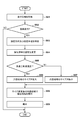
- FIG. 5 is a diagram illustrating a processing flow of the detection area control device 200.
- step S51 the interface unit 201 (IF unit) acquires traveling information (bank angle, vehicle speed, yaw rate, steering angle) indicating the traveling state of the saddle-mounted vehicle 1 detected by the traveling information detection unit 150.
- traveling information bank angle, vehicle speed, yaw rate, steering angle
- step S52 the specific unit 202 determines whether the saddle-mounted vehicle 1 is turning based on the traveling information (bank angle, vehicle speed, yaw rate, steering angle).
- the processing flow ends.
- the specific unit 202 determines that the saddle-mounted vehicle 1 is turning in the determination of step S52 (S52-Yes)
- the specific unit 202 advances the process to step S53.
- step S53 the specific unit 202 turns the saddle-mounted vehicle 1 based on the traveling information (yaw rate, steering angle, bank angle, vehicle speed) of the saddle-mounted vehicle 1 acquired by the interface unit 201 (IF unit). Specify the direction and turning radius.
- step S54 the changing unit 203 changes the setting of the detection area when traveling straight in the rear detecting unit 100 based on the turning direction and the turning radius.
- the changing unit 203 has a shape in which the shape of the detection area set during straight-ahead travel in the detection area of the rear detection unit 100 is curved according to the turning direction and the turning radius. Change to the curved area of.
- step S55 the traveling area determination unit 204 determines that the saddle-mounted vehicle 1 is in a high-speed traveling state equal to or higher than the threshold speed or is less than the threshold speed based on the comparison between the vehicle speed of the saddle-type vehicle 1 and the threshold speed. Determine if the vehicle is running at low speed.
- step S55 when the saddle-mounted vehicle 1 is in the high-speed traveling state (S55-Yes), the traveling area determination unit 204 advances the process to step S56.
- the change unit 203 has the length of the curved region corresponding to the front-rear direction (X direction) of the saddle-type vehicle 1 in the front-rear direction (L1 in FIG. 4) and the vehicle width direction of the saddle-type vehicle 1 (Y).
- the size of the curved region is changed (enlarged) by lengthening at least one of the lengths (W1 in FIG. 4) of the curved region corresponding to the direction).
- step S55 when the saddle-mounted vehicle 1 is in the low-speed traveling state (S55-No), the traveling area determination unit 204 proceeds to the process in step S57.
- the changing portion 203 has the length of the curved region corresponding to the front-rear direction (X direction) of the saddle-type vehicle 1 in the front-rear direction (L1 in FIG. 4) and the vehicle width direction of the saddle-type vehicle 1.
- the size of the curved region is changed (reduced) by shortening at least one of the lengths in the width direction (W1 in FIG. 4) corresponding to (Y direction).
- step S58 the rear detection unit 100 executes the detection process in the curved region after the size change. That is, the rear detection unit 100 detects an object in the detection region (curved region after resizing) behind the vehicle. For example, as described with reference to FIG. 4, another vehicle 410 (FIG. 4) traveling in the curved region 402a behind the saddle-mounted vehicle 1 (own vehicle) is detected by the rear detection unit 100.
- the process proceeds to step S59.
- step S59 the notification control unit 206 controls the display of the notification display unit 224 to notify the driver that an object has been detected by the rear detection unit 100.
- the ROM 205a stores the area pattern according to the turning direction and the turning radius.
- FIG. 6 is a diagram illustrating a table of area patterns stored in the ROM 205a, and if the turning direction and turning radius of the saddle-type vehicle 1 are specified by the specifying unit 202, the changing unit 203 will change the specified turning. It is possible to identify the region pattern corresponding to the direction and the turning radius by referring to the table. For example, when the turning radius is r1 in the right turn, the changing unit 203 specifies the pattern 1, and when the turning radius is r2 in the right turning, the changing unit 203 specifies the pattern 2. In the example of the table shown in FIG. 6, the area pattern in the case of turning right is shown, but the same applies to turning left.
- the length in the X direction indicates the length in the front-rear direction of the area pattern corresponding to the front-rear direction of the saddle-type vehicle 1
- the length in the Y direction corresponds to the vehicle width direction of the saddle-type vehicle 1.
- the length of the area pattern in the width direction is shown. In each region pattern, different values are set for the length in the front-rear direction and the length in the width direction.
- the changing unit 203 determines the length of the region pattern corresponding to the front-rear direction (X direction) of the saddle-type vehicle 1 and the saddle in the front-rear direction. It is possible to change (enlarge) the size of the area pattern by increasing at least one of the lengths in the width direction of the area pattern corresponding to the vehicle width direction of the riding vehicle 1.
- the changing unit 203 determines the length of the region pattern corresponding to the front-rear direction (X direction) of the saddle-mounted vehicle 1 in the front-rear direction. It is possible to change (reduce) the size of the area pattern by shortening at least one of the lengths in the width direction of the area pattern corresponding to the vehicle width direction of the saddle-mounted vehicle 1.
- the changing unit 203 uses this area pattern to change the shape of the detection area set when traveling straight out of the detection areas of the rear detection unit 100. Change to a region with a shape from which the region pattern has been removed.
- FIG. 7 is a diagram illustrating a deformation process of the detection region by the change unit 203 of the second embodiment.
- FIG. 7 shows an example in which radars 101 and 102 are arranged on the left and right as the rear detection unit 100 of the saddle-mounted vehicle 1.
- the radar arrangement in FIG. 7 is an example, and the same can be applied to a configuration in which a single radar is arranged in the rear center of the saddle-mounted vehicle 1.
- the shape of the detection area set when traveling straight ahead in the detection area of the rear detection unit 100 is modeled as a rectangular area shape for simplification.
- the detection areas 701a and 701b shown by the solid lines are the detection areas set when traveling straight ahead (hereinafter, “detection area before change”) among the detection areas of the rear detection unit 100, and the detection area 701a before the change is the radar. Corresponds to the detection area on the left rear side of the saddle-mounted vehicle 1 by 101. Further, the detection area 701b before the change corresponds to the detection area on the right rear side of the saddle-type vehicle 1 by the radar 102.
- the area pattern 710 shown by the broken line corresponds to the pattern 1 (right turn, turning radius r1) shown in the table of FIG.
- the changing unit 203 changes the shape of the detection region before the change to a region having a shape obtained by removing the region pattern 710 from the shape (701a) (hereinafter, “detection region after the change”).
- the area pattern 710 is from the detection area 701a located outside the turning track (turning track 720). Is being removed.
- the example of removing the region pattern from the detection region before the change is not limited to this example, and the region pattern 710 may be removed from the detection region 701a and the detection region 701b before the change.
- the other vehicle 750 behind the saddle-mounted vehicle 1 (own vehicle) is located in the area removed from the detection area 701a before the change by the area pattern 710, and is not detected by the rear detection unit 100.
- the changing unit 203 changes the shape of the detection area set when traveling straight ahead in the detection area of the rear detecting unit 100 to a region having a shape obtained by removing the region pattern from the shape. This prevents the other vehicle 750 traveling at a position away from the turning track (turning track 720) from being erroneously detected as another vehicle following the saddle-mounted vehicle 1 (own vehicle) during turning. Is possible.
- the rear detection means for example, 101, 102 in FIG. 1, 100 in FIG. 2 for detecting an object in the detection region behind the vehicle, and the rear detection means (100, 101, In a saddle-type vehicle (for example, 1 in FIG. 1) having a notification means (for example, 224 in FIGS. 1 and 2) for notifying the driver when the object is detected by 102).
- An acquisition means for example, 201 in FIG. 2) for acquiring the traveling information of the saddle-mounted vehicle (1), and With the specific means for specifying the turning direction and turning radius of the saddle-type vehicle based on the traveling information (for example, 202 in FIG. 2),
- the rear detecting means (100, 101, 102) includes a changing means (for example, 203 in FIG. 2) for changing the setting of the detection area during straight running, based on the turning direction and the turning radius.
- the setting of the detection area in the rear detection unit can be changed based on the turning direction and the turning radius of the saddle-mounted vehicle. Further, by changing the setting of the detection area in the rear detection unit based on the turning direction and the turning radius of the saddle-type vehicle, it is possible to prevent detection omission and erroneous detection.
- the changing means (203) has a shape of a detection area set during straight-ahead traveling in the detection areas of the rear detection means (100, 101, 102). Is changed to a curved region (for example, 401a, 401b in FIG. 4) having a curved shape according to the turning direction and the turning radius.
- the detection omission is prevented by changing the shape of the detection region set when traveling straight to a curved region having a curved shape according to the turning direction and the turning radius. Is possible.
- the saddle-mounted vehicle (1) of the above embodiment is further provided with a storage means (for example, 205 in FIG. 2) for storing a region pattern corresponding to the turning direction and turning radius.
- the changing means (203) changes the shape of the detection region (for example, 701a in FIG. 7) set during the straight running out of the detection regions of the rear detecting means (100, 101, 102) from the shape to the region.
- the pattern (eg, 710 in FIG. 7) is changed to a region of the removed shape (eg, 701a-710).
- erroneous detection can be prevented by changing the shape of the detection region to a region having a shape obtained by removing the region pattern from the shape.
- the saddle-type vehicle (1) of the above-described embodiment wherein the acquisition means (201) is the saddle-type vehicle (1) detected by a yaw rate sensor (for example, 153 in FIG. 2) as the travel information. And the steering angle of the saddle-mounted vehicle (1) detected by the steering angle sensor (for example, 154 in FIG. 2).
- the identifying means (202) identifies the turning direction based on the yaw rate or the steering angle.
- the acquisition means (201) is the saddle-type vehicle (1) detected by a bank angle sensor (for example, 151 in FIG. 2) as the travel information. ) And the vehicle speed of the saddle-mounted vehicle (1) detected by the vehicle speed sensor (for example, 152 in FIG. 2).
- the specifying means (202) specifies the turning radius in the turning direction acquired based on the bank angle and the vehicle speed as the radius of curvature of the curved region.
- the saddle-mounted vehicle of the configuration 5 it is possible to calculate the turning radius in the direction in which the detection region is curved, and the turning radius in the turning direction can be specified as the radius of curvature of the curved region.
- the saddle-type vehicle based on the comparison between the vehicle speed and the threshold speed, the saddle-type vehicle is in a high-speed running state equal to or higher than the threshold speed or is less than the threshold speed. Further provided with a traveling area determination means (for example, 204 in FIG. 2) for determining whether or not the vehicle is in a low-speed traveling state.
- the changing means (203) changes the size of the curved region based on the result of the determination.
- the size of the curved region can be changed based on the running state of the saddle-mounted vehicle.
- the changing means (203) is used when the saddle-mounted vehicle is in a high-speed traveling state (for example, vehicle speed V ⁇ threshold speed Vth).
- the length of at least one of W1) in FIG. 4 is increased to change the size of the curved region (for example, 402a and 402b in FIG. 4).
- the saddle-mounted vehicle of configuration 7 it is possible to change the size of the curved region suitable for high-speed driving based on the traveling state of the saddle-mounted vehicle.
- the changing means (203) is used when the saddle-mounted vehicle is in a low-speed traveling state (for example, vehicle speed V ⁇ threshold speed Vth).
- the length of at least one of W1) in FIG. 4 is shortened to change the size of the curved region.
- the saddle-mounted vehicle of the configuration 8 it is possible to change the size of the curved region suitable for low-speed traveling based on the traveling state of the saddle-mounted vehicle.
- the specific means (202) has an average bank angle within the time based on the bank angle sequentially acquired within a set time and the vehicle speed. And get the average vehicle speed, The specific means (202) corrects the radius of curvature of the curved region based on the average bank angle and the average vehicle speed.
- the radius of curvature of the curved region can be corrected based on the acquired average bank angle and average vehicle speed. This makes it possible to correct the setting of the curved region, which is the detection region of the rear detection unit, according to the state of turning.
- the method for controlling a saddle-mounted vehicle includes a rear detecting means (for example, 101, 102 in FIG. 1, 100 in FIG. 2) for detecting an object in a detection region behind the vehicle, and the rear detecting means (100, 100, According to a control method (for example, FIG. 5) of a saddle-type vehicle (for example, 1 in FIG. 1) having a notification means for notifying the driver when the object is detected by 101, 102).
- the acquisition means (for example, 201 in FIG. 2) acquires the traveling information of the saddle-type vehicle (for example, S51 in FIG. 5).
- a specific step for example, S53 in FIG. 5) in which the specific means (for example, 202 in FIG.
- a changing step (for example, FIG. 2) in which the changing means (for example, 203 in FIG. 2) changes the setting of the detection area when traveling straight in the rear detecting means (100, 101, 102) based on the turning direction and the turning radius. 5 S54) and.
- the setting of the detection area in the rear detection unit can be changed based on the turning direction and the turning radius of the saddle-type vehicle. Further, by changing the setting of the detection area in the rear detection unit based on the turning direction and the turning radius of the saddle-type vehicle, it is possible to prevent detection omission and erroneous detection.
- the control method of the saddle-mounted vehicle of the above embodiment is a detection area of the detection areas of the rear detection means (100, 101, 102) set during straight-ahead travel.
- the shape is changed to a curved region (for example, 401a, 401b in FIG. 4) having a curved shape according to the turning direction and the turning radius.
- the detection omission is prevented by changing the shape of the detection region set during straight running to a curved region having a curved shape according to the turning direction and the turning radius. It is possible to prevent it.
- the method for controlling a saddle-mounted vehicle is a pattern acquisition step (for example, for example) of acquiring the turning pattern from a storage means (for example, 205 in FIG. 2) that stores a region pattern corresponding to the turning direction and the turning radius. It also has 710) in FIG.
- the change step the shape of the detection region set during the straight running of the detection regions of the rear detection means (100, 101, 102) is changed to a region having a shape obtained by removing the region pattern from the shape (the shape is changed). For example, 701a-710).
- erroneous detection can be prevented by changing the shape of the detection region to a region having a shape obtained by removing the region pattern from the shape.
- Configuration 13 The program of the above-described embodiment causes a computer to execute each step of the saddle-type vehicle control method according to any one of the configurations 10 to 12.
- the present invention supplies a program that realizes one or more functions of the above-described embodiment to a system or device via a network or storage medium, and one or more processors in the computer of the system or device reads and executes the program. It can also be realized by the processing to be performed. It can also be realized by a circuit (for example, ASIC) that realizes one or more functions.
- a circuit for example, ASIC
- 1 Saddle-type vehicle, 100: Rear detection unit, 101, 102: Radar 150: Driving information detection unit, 151: Bank angle sensor, 152: Vehicle speed sensor, 153: Yaw rate sensor, 154: Steering angle sensor, 200: Detection area control device, 201: Interface unit (acquisition unit), 202: Specific part, 203: Change part, 204: Travel area judgment part, 206: Notification control unit, 224: Notification display unit
Abstract
A saddle-ridden vehicle having a rearward detection unit for detecting an object in a detection region to the rear of a vehicle, and a notification unit for notifying a driver when an object is detected by the rearward detection unit, the saddle-ridden vehicle being equipped with: an acquisition unit for acquiring travel information for the saddle-ridden vehicle; an identification unit for identifying the turning direction and the turn radius of the saddle-ridden vehicle on the basis of the travel information; and a change unit for changing the straight-ahead-travel detection region settings for the rearward detection unit on the basis of the turning direction and the turn radius.
Description
本発明は、鞍乗型車両、鞍乗型車両の制御方法及びプログラムに関する。
The present invention relates to a saddle-mounted vehicle, a control method and a program for a saddle-mounted vehicle.
特許文献1には、自車両の後方の状況を検出し、後方の検出領域に他車が検出されたときに、ランプの点滅等により、運転者に他車の存在を報知する技術が開示されている。
Patent Document 1 discloses a technique of detecting the situation behind the own vehicle and notifying the driver of the existence of the other vehicle by blinking a lamp or the like when another vehicle is detected in the rear detection area. ing.
しかしながら、特許文献1の構成では、直進走行時及び旋回走行時において、後方の検出領域の設定は固定的であるため、車両の旋回方向及び旋回半径によっては、後方の検出領域において運転者が視認しにくい領域(ブラインド領域)が発生し得る。
However, in the configuration of Patent Document 1, since the setting of the rear detection area is fixed during straight-ahead driving and turning, the driver can visually recognize the rear detection area depending on the turning direction and turning radius of the vehicle. A difficult area (blind area) may occur.
本発明は、従来技術の課題に鑑み、後方検出部における検出領域の設定を鞍乗型車両の旋回方向及び旋回半径に基づいて変更することが可能な技術を提供することを目的とする。
An object of the present invention is to provide a technique capable of changing the setting of the detection area in the rear detection unit based on the turning direction and the turning radius of the saddle-type vehicle in view of the problems of the prior art.
本発明の一態様による鞍乗型車両は、車両後方の検出領域における物体を検出する後方検出手段と、前記後方検出手段により前記物体が検出された場合に、運転者に対して報知を行う報知手段と、を有する鞍乗型車両であって、
前記鞍乗型車両の走行情報を取得する取得手段と、
前記走行情報に基づいて、前記鞍乗型車両の旋回方向及び旋回半径を特定する特定手段と、
前記後方検出手段における直進走行時の検出領域の設定を前記旋回方向及び旋回半径に基づいて変更する変更手段と、を備えることを特徴とする。 The saddle-mounted vehicle according to one aspect of the present invention has a rear detection means for detecting an object in a detection region behind the vehicle and a notification for notifying the driver when the object is detected by the rear detection means. A saddle-type vehicle having means and
An acquisition means for acquiring the traveling information of the saddle-type vehicle, and
A specific means for specifying the turning direction and turning radius of the saddle-type vehicle based on the traveling information, and
It is characterized by including a changing means for changing the setting of the detection area when traveling straight in the rear detecting means based on the turning direction and the turning radius.
本発明の他の態様による鞍乗型車両の制御方法は、車両後方の検出領域における物体を検出する後方検出手段と、前記後方検出手段により前記物体が検出された場合に、運転者に対して報知を行う報知手段と、を有する鞍乗型車両の制御方法であって、
取得手段が、前記鞍乗型車両の走行情報を取得する取得工程と、
特定手段が、前記走行情報に基づいて、前記鞍乗型車両の旋回方向及び旋回半径を特定する特定工程と、
変更手段が、前記後方検出手段における直進走行時の検出領域の設定を前記旋回方向及び旋回半径に基づいて変更する変更工程と、を有することを特徴とする。 The method for controlling a saddle-type vehicle according to another aspect of the present invention is to the rear detecting means for detecting an object in the detection region behind the vehicle and to the driver when the object is detected by the rear detecting means. It is a control method of a saddle-type vehicle having a notification means for performing notification.
The acquisition process of acquiring the traveling information of the saddle-type vehicle and the acquisition means
A specific step in which the specific means specifies the turning direction and turning radius of the saddle-type vehicle based on the traveling information.
The changing means includes a changing step of changing the setting of the detection area when traveling straight in the rear detecting means based on the turning direction and the turning radius.
本発明によれば、後方検出部における検出領域の設定を鞍乗型車両の旋回方向及び旋回半径に基づいて変更することが可能になる。
According to the present invention, it is possible to change the setting of the detection area in the rear detection unit based on the turning direction and turning radius of the saddle-type vehicle.
本発明のその他の特徴及び利点は、添付図面を参照とした以下の説明により明らかになるであろう。なお、添付図面においては、同じ若しくは同様の構成には、同じ参照番号を付す。
Other features and advantages of the present invention will be clarified by the following description with reference to the accompanying drawings. In the attached drawings, the same or similar configurations are designated by the same reference numbers.
添付図面は明細書に含まれ、その一部を構成し、本発明の実施の形態を示し、その記述と共に本発明の原理を説明するために用いられる。
実施形態における自動二輪車(鞍乗型車両)の構成を例示する図。
検出領域制御装置の機能構成を示すブロック図。
旋回半径を求める演算例を説明する図。
変更部による検出領域の変形処理を説明する図。
検出領域制御装置の処理の流れを説明する図。
第2実施形態のテーブルを例示する図。
第2実施形態の変更部による検出領域の変形処理を説明する図。
The accompanying drawings are included in the specification and are used to form a part thereof, show embodiments of the present invention, and explain the principles of the present invention together with the description thereof.
The figure which illustrates the structure of the motorcycle (saddle type vehicle) in embodiment. The block diagram which shows the functional structure of the detection area control device. The figure explaining the calculation example of finding the turning radius. The figure explaining the transformation processing of the detection area by a change part. The figure explaining the process flow of the detection area control apparatus. The figure which illustrates the table of 2nd Embodiment. The figure explaining the transformation processing of the detection area by the change part of 2nd Embodiment.
以下、図面を参照しながら本発明の実施形態について説明する。この実施形態に記載されている構成要素はあくまで例示であり、以下の実施形態によって限定されるわけではない。
Hereinafter, embodiments of the present invention will be described with reference to the drawings. The components described in this embodiment are merely exemplary and are not limited by the following embodiments.
[第1実施形態]
(自動二輪車(鞍乗型車両)の構成)
図1は、本発明の実施形態における鞍乗型車両1の構成を例示する図である。図1の1Aは、鞍乗型車両1の左側面図であり、図1の1Bは鞍乗型車両1の上面図、図1の1Cは、鞍乗型車両1の後面図である。図1において、X方向は鞍乗型車両1の前後方向を示し、Y方向は鞍乗型車両1の車幅方向を示す。また、Z方向は鞍乗型車両1の上下方向を示す。 [First Embodiment]
(Structure of motorcycle (saddle-type vehicle))
FIG. 1 is a diagram illustrating a configuration of a saddle-mountedvehicle 1 according to an embodiment of the present invention. 1A of FIG. 1 is a left side view of the saddle-mounted vehicle 1, 1B of FIG. 1 is a top view of the saddle-mounted vehicle 1, and 1C of FIG. 1 is a rear view of the saddle-mounted vehicle 1. In FIG. 1, the X direction indicates the front-rear direction of the saddle-mounted vehicle 1, and the Y direction indicates the vehicle width direction of the saddle-mounted vehicle 1. Further, the Z direction indicates the vertical direction of the saddle-mounted vehicle 1.
(自動二輪車(鞍乗型車両)の構成)
図1は、本発明の実施形態における鞍乗型車両1の構成を例示する図である。図1の1Aは、鞍乗型車両1の左側面図であり、図1の1Bは鞍乗型車両1の上面図、図1の1Cは、鞍乗型車両1の後面図である。図1において、X方向は鞍乗型車両1の前後方向を示し、Y方向は鞍乗型車両1の車幅方向を示す。また、Z方向は鞍乗型車両1の上下方向を示す。 [First Embodiment]
(Structure of motorcycle (saddle-type vehicle))
FIG. 1 is a diagram illustrating a configuration of a saddle-mounted
鞍乗型車両1において、前輪2は左右一対のフロントフォーク3の下端部に軸支される。左右フロントフォーク3の上部は、ステアリングステム4を介して車体フレーム5の前端部のヘッドパイプ6に操向可能に枢支される。
In the saddle-mounted vehicle 1, the front wheels 2 are pivotally supported by the lower ends of a pair of left and right front forks 3. The upper parts of the left and right front forks 3 are pivotally supported by the head pipe 6 at the front end of the vehicle body frame 5 via the steering stem 4.
鞍乗型車両1はヘッドパイプ6に取付けられたハンドルバー19により操舵される。ハンドルバー19の左右の各端部には運転者が把持するハンドルグリップが設けられている。また、ハンドルバー19には、左右のハンドルグリップに隣接してブレーキレバーやクラッチレバー等が設けられている(不図示)。鞍乗型車両1の後輪7は、車体後部下側で前後に延びるアーム8の後端部に軸支される。アーム8の前端部は、車体フレーム5の前後中間部で上下に揺動可能に枢支される。
The saddle-mounted vehicle 1 is steered by the handlebar 19 attached to the head pipe 6. Handle grips gripped by the driver are provided at the left and right ends of the handlebar 19. Further, the handlebar 19 is provided with a brake lever, a clutch lever, and the like adjacent to the left and right handle grips (not shown). The rear wheel 7 of the saddle-mounted vehicle 1 is pivotally supported by the rear end of the arm 8 extending forward and backward on the lower rear side of the vehicle body. The front end portion of the arm 8 is pivotally supported so as to be swingable up and down at the front-rear intermediate portion of the vehicle body frame 5.
車体フレーム5には、鞍乗型車両1の原動機であるエンジン(内燃機関)10が搭載される。エンジン10の上方には燃料タンク11が配置され、燃料タンク11の後方には、自動二輪車1の運転者が着座するシート12が配置される。運転者が着座するシート12の後部に物品収納用のトランクケース18が配置されている。車体前部には車体フレーム5に支持されたフロントカウル13が装着される。フロントカウル13の前部上側にはスクリーン14が設けられる。フロントカウル13及びスクリーン14の内側にはメータパネル15が配置される。メータパネル15は車速、エンジン回転数等の車両の状態の等の各種の情報を表示する。鞍乗型車両1の後方部にはテールウィンカー16及びテールライト17が設けられている。
The engine (internal combustion engine) 10, which is the prime mover of the saddle-mounted vehicle 1, is mounted on the body frame 5. A fuel tank 11 is arranged above the engine 10, and a seat 12 on which the driver of the motorcycle 1 is seated is arranged behind the fuel tank 11. A trunk case 18 for storing articles is arranged at the rear of the seat 12 on which the driver sits. A front cowl 13 supported by a vehicle body frame 5 is mounted on the front portion of the vehicle body. A screen 14 is provided on the upper front side of the front cowl 13. The meter panel 15 is arranged inside the front cowl 13 and the screen 14. The meter panel 15 displays various information such as vehicle speed, engine speed, and other vehicle conditions. A tail winker 16 and a tail light 17 are provided at the rear portion of the saddle-mounted vehicle 1.
鞍乗型車両1には、車両後方の検出領域における物体を検出する後方検出部100として、レーダ101、102が配置されている。図1に示す例では、レーダ101、102は、鞍乗型車両1の左右後方の位置にそれぞれ配置されている。レーダ101は鞍乗型車両1の左側後方の検出領域における物体を検出する。また、レーダ102は鞍乗型車両1の右側後方の検出領域における物体を検出する。
In the saddle-mounted vehicle 1, radars 101 and 102 are arranged as rear detection units 100 for detecting an object in the detection region behind the vehicle. In the example shown in FIG. 1, the radars 101 and 102 are arranged at the left and right rear positions of the saddle-mounted vehicle 1, respectively. The radar 101 detects an object in the detection region on the left rear side of the saddle-mounted vehicle 1. Further, the radar 102 detects an object in the detection region on the right rear side of the saddle-mounted vehicle 1.
尚、図1に示す後方検出部100の配置は例示的なものであり、鞍乗型車両1の後方中央に単一のレーダを配置してもよいし、左右後方に2つのレーダを配置し、後方中央に1つのレーダを配置してもよい。後方検出部100におけるセンサの種類はレーダの他、例えば、ライダー(LIDAR)であってもよい。また、図1の例では、後方検出部100をトランクケース18内に配置したが、後方検出部100の配置はこの位置に限られない。例えば、鞍乗型車両1のサドルバック20内も後方検出部100の配置箇所になり得る。
The arrangement of the rear detection unit 100 shown in FIG. 1 is an example, and a single radar may be arranged in the rear center of the saddle-mounted vehicle 1, or two radars may be arranged in the left and right rear. , One radar may be placed in the rear center. The type of sensor in the rear detection unit 100 may be, for example, a lidar in addition to the radar. Further, in the example of FIG. 1, the rear detection unit 100 is arranged in the trunk case 18, but the arrangement of the rear detection unit 100 is not limited to this position. For example, the inside of the saddle back 20 of the saddle-mounted vehicle 1 can also be a location where the rear detection unit 100 is arranged.
鞍乗型車両1の車幅方向(y方向)には、左右のミラーユニット22が設けられている。左右のミラーユニット22は、ミラーハウジング222と、サイドミラー(鏡面部)223と、報知表示部224とを備える。ミラーハウジング222は、後方側が開口した中空体であり、その開口を塞ぐようにサイドミラー(鏡面部)223がミラーハウジング222に取り付けられている。運転者はサイドミラー223によって左右後方を視認することが可能である。
Left and right mirror units 22 are provided in the vehicle width direction (y direction) of the saddle-mounted vehicle 1. The left and right mirror units 22 include a mirror housing 222, side mirrors (mirror surface portions) 223, and a notification display unit 224. The mirror housing 222 is a hollow body having an opening on the rear side, and a side mirror (mirror surface portion) 223 is attached to the mirror housing 222 so as to close the opening. The driver can visually recognize the left and right rear by the side mirror 223.
本実施形態の鞍乗型車両1は、後方検出部100により物体が検出された場合に、運転者に対して報知を行う報知部を有する。ミラーユニット22の報知表示部224は、運転者に対して報知を行う報知部として機能する。報知表示部224は、LED等の発光素子と発光素子を支持する基板と報知表示部224の正面を覆うカバーレンズ等とを備えた発光装置である。サイドミラー223の一部に開口部を形成し、この開口部に報知表示部224を配置することにより、ミラーユニット22に報知表示部224を設けることができる。
The saddle-mounted vehicle 1 of the present embodiment has a notification unit that notifies the driver when an object is detected by the rear detection unit 100. The notification display unit 224 of the mirror unit 22 functions as a notification unit that notifies the driver. The notification display unit 224 is a light emitting device including a light emitting element such as an LED, a substrate that supports the light emitting element, and a cover lens or the like that covers the front surface of the notification display unit 224. By forming an opening in a part of the side mirror 223 and arranging the notification display unit 224 in the opening, the notification display unit 224 can be provided in the mirror unit 22.
尚、図1に示す報知表示部224の配置は例示的なものであり、報知表示部224の配置はこの位置に限られない。例えば、メータパネル15も報知表示部224の配置箇所になり得る。
The arrangement of the notification display unit 224 shown in FIG. 1 is an example, and the arrangement of the notification display unit 224 is not limited to this position. For example, the meter panel 15 can also be a location for the notification display unit 224.
(検出領域制御装置200の構成)
図2は、本実施形態に係る検出領域制御装置200の機能構成を示すブロック図である。鞍乗型車両1には、後方検出部100、走行情報検出部150及び検出領域制御装置200が設けられている。走行情報検出部150は鞍乗型車両1の走行状態を示す走行情報(バンク角、車速、ヨーレート、操舵角)を検出する。検出領域制御装置200は後方検出部100における検出領域の設定を鞍乗型車両1の走行状態を示す走行情報に基づいて変更することが可能である。 (Configuration of detection area control device 200)
FIG. 2 is a block diagram showing a functional configuration of the detectionarea control device 200 according to the present embodiment. The saddle-mounted vehicle 1 is provided with a rear detection unit 100, a traveling information detection unit 150, and a detection area control device 200. The traveling information detection unit 150 detects traveling information (bank angle, vehicle speed, yaw rate, steering angle) indicating the traveling state of the saddle-mounted vehicle 1. The detection area control device 200 can change the setting of the detection area in the rear detection unit 100 based on the travel information indicating the traveling state of the saddle-mounted vehicle 1.
図2は、本実施形態に係る検出領域制御装置200の機能構成を示すブロック図である。鞍乗型車両1には、後方検出部100、走行情報検出部150及び検出領域制御装置200が設けられている。走行情報検出部150は鞍乗型車両1の走行状態を示す走行情報(バンク角、車速、ヨーレート、操舵角)を検出する。検出領域制御装置200は後方検出部100における検出領域の設定を鞍乗型車両1の走行状態を示す走行情報に基づいて変更することが可能である。 (Configuration of detection area control device 200)
FIG. 2 is a block diagram showing a functional configuration of the detection
検出領域制御装置200は、インタフェース部201(IF部)、特定部202、変更部203、走行域判定部204、記憶部205(ROM205a、RAM205b)及び報知制御部206を有する。ここで、演算及び判定処理を行う機能構成である、特定部202、変更部203及び走行域判定部204は、例えば、一つ又は複数のCPU(central processing unit)、あるいは、記憶部205から読み込んだプログラムを用いて、各部の機能が構成される。各部の機能構成は、同様の機能を果たすのであれば、それらを集積回路などで構成してもよい。
The detection area control device 200 includes an interface unit 201 (IF unit), a specific unit 202, a change unit 203, a traveling area determination unit 204, a storage unit 205 (ROM205a, RAM205b), and a notification control unit 206. Here, the specific unit 202, the change unit 203, and the traveling area determination unit 204, which are functional configurations for performing calculation and determination processing, are read from, for example, one or a plurality of CPUs (central processing units) or a storage unit 205. The functions of each part are configured using the program. The functional configuration of each part may be configured by an integrated circuit or the like as long as it fulfills the same function.
(インタフェース部201)
インタフェース部201(IF部)は、後方検出部100と、走行情報検出部150と、報知表示部224との間のインタフェースとして機能し、インタフェース部201には、例えば、所定の通信プロトコルによるデータ通信が可能な通信インタフェースが含まれる。ここで、通信プロトコルには、例えば、K-Line通信、CAN通信、シリアル通信などが含まれる。 (Interface section 201)
The interface unit 201 (IF unit) functions as an interface between therear detection unit 100, the traveling information detection unit 150, and the notification display unit 224, and the interface unit 201 is subjected to, for example, data communication by a predetermined communication protocol. Includes communication interfaces that allow. Here, the communication protocol includes, for example, K-Line communication, CAN communication, serial communication, and the like.
インタフェース部201(IF部)は、後方検出部100と、走行情報検出部150と、報知表示部224との間のインタフェースとして機能し、インタフェース部201には、例えば、所定の通信プロトコルによるデータ通信が可能な通信インタフェースが含まれる。ここで、通信プロトコルには、例えば、K-Line通信、CAN通信、シリアル通信などが含まれる。 (Interface section 201)
The interface unit 201 (IF unit) functions as an interface between the
インタフェース部201は、走行情報検出部150で検出された鞍乗型車両1の走行状態を示す走行情報(バンク角、車速、ヨーレート、操舵角)を取得することができる。
The interface unit 201 can acquire travel information (bank angle, vehicle speed, yaw rate, steering angle) indicating the travel state of the saddle-mounted vehicle 1 detected by the travel information detection unit 150.
走行情報検出部150は鞍乗型車両1の走行状態を示す走行情報を検出することが可能であり、走行情報検出部150には、例えば、鞍乗型車両1に搭載されている複数種のセンサ(例えば、バンク角センサ151、車速センサ152、ヨーレートセンサ153、操舵角センサ154等)が含まれる。
The traveling information detection unit 150 can detect traveling information indicating the traveling state of the saddle-mounted vehicle 1, and the traveling information detecting unit 150 can detect, for example, a plurality of types of traveling information mounted on the saddle-mounted vehicle 1. Sensors (eg, bank angle sensor 151, vehicle speed sensor 152, yaw rate sensor 153, steering angle sensor 154, etc.) are included.
バンク角センサ151は、鞍乗型車両1の傾斜角度(バンク角α:図3)を検出するセンサである。尚、バンク角センサ151の代わりにGセンサを用いることも可能である。Gセンサ(加速度センサ)は、鞍乗型車両1の加速度(速度の変化率)を計測するセンサであり、3軸(X軸・Y軸・Z軸)方向の加速度を測定することが可能である。例えば、図3に示すように、GセンサのY方向の測定値に基づいて、鞍乗型車両1の傾斜角度を検出することができる。
The bank angle sensor 151 is a sensor that detects the inclination angle (bank angle α: FIG. 3) of the saddle-mounted vehicle 1. It is also possible to use a G sensor instead of the bank angle sensor 151. The G sensor (accelerometer) is a sensor that measures the acceleration (speed change rate) of the saddle-mounted vehicle 1 and can measure the acceleration in the three axes (X-axis, Y-axis, and Z-axis). is there. For example, as shown in FIG. 3, the inclination angle of the saddle-mounted vehicle 1 can be detected based on the measured value in the Y direction of the G sensor.
車速センサ152は、鞍乗型車両1の走行速度を検出するセンサであり、例えば、鞍乗型車両1の車輪の回転数に応じた回転速度(速度)を検出する。また、ヨーレートセンサ153は、鞍乗型車両1のヨーレート(回転角速度)を検出する。操舵角センサ154は、鞍乗型車両1のハンドルバー19の舵角を検出する。バンク角センサ151、車速センサ152、ヨーレートセンサ153及び操舵角センサ154は、鞍乗型車両1のイグニッションがオンすると、検出を繰り返し実行する。
The vehicle speed sensor 152 is a sensor that detects the traveling speed of the saddle-mounted vehicle 1, and for example, detects the rotation speed (speed) according to the number of rotations of the wheels of the saddle-mounted vehicle 1. Further, the yaw rate sensor 153 detects the yaw rate (rotation angular velocity) of the saddle-mounted vehicle 1. The steering angle sensor 154 detects the steering angle of the handlebar 19 of the saddle-mounted vehicle 1. The bank angle sensor 151, the vehicle speed sensor 152, the yaw rate sensor 153, and the steering angle sensor 154 repeatedly execute detection when the ignition of the saddle-mounted vehicle 1 is turned on.
(特定部202)
特定部202は、インタフェース部201(IF部)により取得された鞍乗型車両1の走行情報(ヨーレート、操舵角、バンク角、車速)に基づいて、鞍乗型車両1の旋回方向及び旋回半径を特定する。 (Specific part 202)
Thespecific unit 202 describes the turning direction and turning radius of the saddle-mounted vehicle 1 based on the traveling information (yaw rate, steering angle, bank angle, vehicle speed) of the saddle-mounted vehicle 1 acquired by the interface unit 201 (IF unit). To identify.
特定部202は、インタフェース部201(IF部)により取得された鞍乗型車両1の走行情報(ヨーレート、操舵角、バンク角、車速)に基づいて、鞍乗型車両1の旋回方向及び旋回半径を特定する。 (Specific part 202)
The
特定部202は、走行情報のうち、例えば、ヨーレートまたは操舵角に基づいて、旋回方向を特定する。また、特定部202は、走行情報のうち、例えば、バンク角および車速に基づいて旋回方向における旋回半径を特定する。
The identification unit 202 specifies the turning direction based on, for example, the yaw rate or the steering angle in the traveling information. Further, the specifying unit 202 specifies the turning radius in the turning direction based on, for example, the bank angle and the vehicle speed in the traveling information.
ここで、図3は旋回半径を求める演算例を説明する図である。例えば、図3に示すように、鞍乗型車両1及び運転者の質量を仮想的にMとし、重力加速度をgとし、鞍乗型車両1のバンク角(傾斜角)をαとした場合、鞍乗型車両1を傾斜させる方向の力(F1)は、F1=Mg・sinαとなる。
Here, FIG. 3 is a diagram for explaining an example of calculation for obtaining the turning radius. For example, as shown in FIG. 3, when the mass of the saddle-type vehicle 1 and the driver is virtually M, the gravitational acceleration is g, and the bank angle (tilt angle) of the saddle-type vehicle 1 is α. The force (F1) in the direction of tilting the saddle-mounted vehicle 1 is F1 = Mg · sinα.
旋回半径r、車速Vにより乗型車両1が旋回走行する際に作用する遠心力F2はM・(V2/r)である。そして、乗型車両1が旋回走行する際に鞍乗型車両1を起こす方向に作用する力(F3)は、F3=F2・cosαとなる。
The centrifugal force F2 acting when the riding vehicle 1 turns and travels due to the turning radius r and the vehicle speed V is M · (V 2 / r). Then, the force (F3) acting in the direction of raising the saddle-mounted vehicle 1 when the riding-type vehicle 1 makes a turn is F3 = F2 · cosα.
鞍乗型車両1を傾斜させる方向の力F1と鞍乗型車両1を起こす方向に作用する力F3とが釣り合うため、Mg・sinα=M(V2/r)・cosαという関係が成り立つ。
Since the force F1 in the direction of tilting the saddle-mounted vehicle 1 and the force F3 acting in the direction of raising the saddle-mounted vehicle 1 are balanced, the relationship of Mg · sin α = M (V 2 / r) · cos α is established.
特定部202は、この関係式に基づいた演算処理を走行経路において逐次実行することにより、旋回半径を取得することができる。演算処理において、特定部202は、バンク角センサ151の検出結果としてバンク角αと、車速センサ152の検出結果として車速Vとを取得することが可能であり、特定部202は、バンク角αおよび車速Vに基づいて旋回方向における旋回半径rを、r=V2/(g・tanα)として特定することができる。
The specific unit 202 can acquire the turning radius by sequentially executing arithmetic processing based on this relational expression in the traveling path. In the arithmetic processing, the specific unit 202 can acquire the bank angle α as the detection result of the bank angle sensor 151 and the vehicle speed V as the detection result of the vehicle speed sensor 152, and the specific unit 202 can acquire the bank angle α and the vehicle speed V as the detection result of the vehicle speed sensor 152. The turning radius r in the turning direction can be specified as r = V 2 / (g · tan α) based on the vehicle speed V.
尚、上記の関係式では、バンク角センサ151と車速センサ152の検出結果を用いて旋回半径rを特定したが、上記の関係式に基づく演算は一例であり、この例に限定されるものではない。例えば、バンク角センサ151の検出結果(バンク角(傾斜角):α)とヨーレートセンサ153の検出結果(回転角速度ω)とを用いて旋回半径rを特定することも可能である。
In the above relational expression, the turning radius r is specified by using the detection results of the bank angle sensor 151 and the vehicle speed sensor 152, but the calculation based on the above relational expression is an example, and is not limited to this example. Absent. For example, it is also possible to specify the turning radius r by using the detection result of the bank angle sensor 151 (bank angle (tilt angle): α) and the detection result of the yaw rate sensor 153 (rotation angular velocity ω).
(変更部203)
特定部202により鞍乗型車両1の旋回方向及び旋回半径が特定されると、変更部203は後方検出部100における直進走行時の検出領域の設定を旋回方向及び旋回半径に基づいて変更する。変更部203は、後方検出部100の検出領域のうち直進走行時に設定された検出領域の形状を、旋回方向及び旋回半径に応じて湾曲させた形状の湾曲領域に変更する。 (Change part 203)
When the turning direction and turning radius of the saddle-mountedvehicle 1 are specified by the specifying unit 202, the changing unit 203 changes the setting of the detection area when traveling straight in the rear detecting unit 100 based on the turning direction and turning radius. The changing unit 203 changes the shape of the detection area set when traveling straight ahead in the detection area of the rear detecting unit 100 to a curved region having a curved shape according to the turning direction and the turning radius.
特定部202により鞍乗型車両1の旋回方向及び旋回半径が特定されると、変更部203は後方検出部100における直進走行時の検出領域の設定を旋回方向及び旋回半径に基づいて変更する。変更部203は、後方検出部100の検出領域のうち直進走行時に設定された検出領域の形状を、旋回方向及び旋回半径に応じて湾曲させた形状の湾曲領域に変更する。 (Change part 203)
When the turning direction and turning radius of the saddle-mounted
先に説明した特定部202は、バンク角および車速に基づいて取得した旋回方向における旋回半径を湾曲領域の曲率半径として特定する。特定部202は、設定した時間内に逐次取得したバンク角と、車速とに基づいて、時間内の平均バンク角と、平均車速とを取得する。特定部202は、平均バンク角と平均車速とに基づいて、湾曲領域の曲率半径を補正することができる。これにより、後方検出部の検出領域である湾曲領域の設定を、旋回走行の状態に応じて補正することが可能になる。
The specific unit 202 described above specifies the turning radius in the turning direction acquired based on the bank angle and the vehicle speed as the radius of curvature of the curved region. The specific unit 202 acquires the average bank angle within the time and the average vehicle speed based on the bank angle and the vehicle speed sequentially acquired within the set time. The specific unit 202 can correct the radius of curvature of the curved region based on the average bank angle and the average vehicle speed. This makes it possible to correct the setting of the curved region, which is the detection region of the rear detection unit, according to the state of turning.
図4は変更部203による検出領域の変形処理を説明する図である。図4は、鞍乗型車両1の後方検出部100として、レーダ101、102が左右に配置されている例を示している。尚、図4におけるレーダの配置は例示的なものであり、鞍乗型車両1の後方中央に単一のレーダを配置した構成でも同様に適用することが可能である。
FIG. 4 is a diagram for explaining the deformation processing of the detection area by the change unit 203. FIG. 4 shows an example in which radars 101 and 102 are arranged on the left and right as the rear detection unit 100 of the saddle-mounted vehicle 1. The radar arrangement in FIG. 4 is an example, and the same can be applied to a configuration in which a single radar is arranged in the rear center of the saddle-mounted vehicle 1.
後方検出部100の検出領域は二次元的な広がりを有する領域である。図4の例では、後方検出部100の検出領域のうち直進走行時に設定された検出領域の形状を、簡単化のため矩形状の領域形状としてモデル化している(検出領域401a、401b)。
The detection area of the rear detection unit 100 is a region having a two-dimensional spread. In the example of FIG. 4, the shape of the detection area set when traveling straight ahead in the detection area of the rear detection unit 100 is modeled as a rectangular area shape for simplification ( detection areas 401a and 401b).
破線で示す検出領域401a、401bは、後方検出部100の検出領域のうち直進走行時に設定された検出領域(以下、「変更前の検出領域」ともいう)であり、変更前の検出領域401aは、レーダ101による鞍乗型車両1の左側後方の検出領域に対応する。また、変更前の検出領域401bは、レーダ102による鞍乗型車両1の右側後方の検出領域に対応する。
The detection areas 401a and 401b shown by the broken lines are the detection areas set when traveling straight ahead (hereinafter, also referred to as “detection area before change”) in the detection area of the rear detection unit 100, and the detection area 401a before change is , Corresponds to the detection area on the left rear side of the saddle-mounted vehicle 1 by the radar 101. Further, the detection area 401b before the change corresponds to the detection area on the right rear side of the saddle-type vehicle 1 by the radar 102.
変更部203は変更前の検出領域の形状を旋回方向及び旋回半径に応じて湾曲させた形状の湾曲領域(以下、「変更後の検出領域」ともいう)に変更する。実線で示す領域は、変更部203による変更後の検出領域を示しており、変更後の湾曲領域402aはレーダ101による鞍乗型車両1の左側後方の検出領域に対応する。また、変更後の湾曲領域402bはレーダ102による鞍乗型車両1の右側後方の検出領域に対応する。
The change unit 203 changes the shape of the detection area before the change to a curved area having a curved shape according to the turning direction and the turning radius (hereinafter, also referred to as “the detected area after the change”). The area shown by the solid line indicates the detection area after the change by the change unit 203, and the curved area 402a after the change corresponds to the detection area on the left rear side of the saddle-mounted vehicle 1 by the radar 101. Further, the modified curved region 402b corresponds to the detection region on the right rear side of the saddle-mounted vehicle 1 by the radar 102.
図4の例では、鞍乗型車両1は右旋回をした例を示しており、旋回軌道420における旋回半径はrである。変更部203は、後方検出部100における直進走行時の検出領域の設定(矩形状に設定された検出領域(検出領域401a、検出領域401b))を鞍乗型車両1の旋回方向及び旋回半径に基づいて変更する。すなわち、変更部203は、後方検出部100の検出領域のうち直進走行時に設定された検出領域の形状(矩形状の検出領域)を旋回方向(右旋回)及び旋回半径(r)に応じて湾曲させた形状の湾曲領域(湾曲領域402a、湾曲領域402b)に変更する。
In the example of FIG. 4, the saddle-mounted vehicle 1 shows an example of turning right, and the turning radius in the turning track 420 is r. The change unit 203 sets the detection area when traveling straight in the rear detection unit 100 (the detection area set in a rectangular shape (detection area 401a, detection area 401b)) to the turning direction and turning radius of the saddle-type vehicle 1. Change based on. That is, the changing unit 203 changes the shape (rectangular detection area) of the detection area set when traveling straight ahead in the detection area of the rear detection unit 100 according to the turning direction (right turning) and the turning radius (r). It is changed to a curved region (curved region 402a, curved region 402b) having a curved shape.
図4において、鞍乗型車両1(自車両)の後方を走行している他車両410は、変更前の検出領域401a、検出領域401bにおいては検出領域外を走行しているため、後方検出部100により検出されない。しかしながら、検出領域の形状を旋回方向及び旋回半径に応じて湾曲させた形状の湾曲領域に変更した場合、他車両410は変更後の湾曲領域402a内を走行しているため、後方検出部100により検出される。このように、後方検出部100における直進走行時の検出領域の設定を鞍乗型車両の旋回方向及び旋回半径に基づいて変更することにより、検出漏れや誤検出を防止することが可能となる。
In FIG. 4, since the other vehicle 410 traveling behind the saddle-mounted vehicle 1 (own vehicle) is traveling outside the detection area in the detection area 401a and the detection area 401b before the change, the rear detection unit Not detected by 100. However, when the shape of the detection region is changed to a curved region having a curved shape according to the turning direction and the turning radius, since the other vehicle 410 is traveling in the changed curved region 402a, the rear detection unit 100 causes the detection region to travel. Detected. In this way, by changing the setting of the detection area in the rear detection unit 100 when traveling straight ahead based on the turning direction and turning radius of the saddle-mounted vehicle, it is possible to prevent detection omission and erroneous detection.
(走行域判定部204)
走行域判定部204は、鞍乗型車両1の車速と閾値速度との比較に基づいて、鞍乗型車両1が閾値速度以上の高速走行状態であるか、当該閾値速度未満の低速走行状態であるかを判定する。変更部203は、走行域判定部204の判定の結果に基づいて、湾曲領域(図4の湾曲領域402a、湾曲領域402b)のサイズを変更する。 (Traveling area determination unit 204)
Based on the comparison between the vehicle speed of the saddle-mountedvehicle 1 and the threshold speed, the traveling area determination unit 204 determines that the saddle-mounted vehicle 1 is in a high-speed traveling state equal to or higher than the threshold speed or in a low-speed traveling state lower than the threshold speed. Determine if there is. The changing unit 203 changes the size of the curved region (curved region 402a and curved region 402b in FIG. 4) based on the determination result of the traveling area determination unit 204.
走行域判定部204は、鞍乗型車両1の車速と閾値速度との比較に基づいて、鞍乗型車両1が閾値速度以上の高速走行状態であるか、当該閾値速度未満の低速走行状態であるかを判定する。変更部203は、走行域判定部204の判定の結果に基づいて、湾曲領域(図4の湾曲領域402a、湾曲領域402b)のサイズを変更する。 (Traveling area determination unit 204)
Based on the comparison between the vehicle speed of the saddle-mounted
鞍乗型車両1が高速走行状態である場合に、変更部203は、鞍乗型車両1の前後方向(X方向)に対応した湾曲領域の前後方向長さ、及び鞍乗型車両1の車幅方向(Y方向)に対応した湾曲領域の幅方向長さのうち、少なくともいずれか一方の長さを長くして湾曲領域のサイズを変更(拡大)する。
When the saddle-type vehicle 1 is in a high-speed traveling state, the changing unit 203 has the length of the curved region corresponding to the front-rear direction (X direction) of the saddle-type vehicle 1 and the vehicle of the saddle-type vehicle 1. Of the lengths in the width direction of the curved region corresponding to the width direction (Y direction), at least one of them is lengthened to change (enlarge) the size of the curved region.
例えば、車速センサ152で検出された鞍乗型車両1の車速Vが閾値速度Vth以上場合(V≧Vth)、車速Vに応じて、湾曲領域の前後方向長さ(図4のL1)及び湾曲領域の幅方向長さ(図4のW1)のうち、少なくともいずれか一方の長さを長くして湾曲領域のサイズを変更(拡大)する。この場合、車速Vが所定の速度増加するごとに、変更部203は、湾曲領域の前後方向長さ及び湾曲領域の幅方向長さのうち、いずれか一方の長さを所定値長くして湾曲領域のサイズを変更(拡大)する。これにより、広い検出領域で検出を行うことが可能となり、高速走行に適した検出が可能となる。
For example, when the vehicle speed V of the saddle-mounted vehicle 1 detected by the vehicle speed sensor 152 is equal to or higher than the threshold speed Vth (V ≧ Vth), the length of the curved region in the front-rear direction (L1 in FIG. 4) and the curvature are curved according to the vehicle speed V. The size of the curved region is changed (enlarged) by increasing the length of at least one of the lengths in the width direction of the region (W1 in FIG. 4). In this case, each time the vehicle speed V increases by a predetermined speed, the changing portion 203 bends by lengthening one of the length of the curved region in the front-rear direction and the length of the curved region in the width direction by a predetermined value. Resize (enlarge) the area. This makes it possible to perform detection in a wide detection area, and detection suitable for high-speed driving becomes possible.
また、鞍乗型車両1が低速走行状態である場合に、変更部203は、鞍乗型車両1の前後方向(X方向)に対応した湾曲領域の前後方向長さ、及び鞍乗型車両1の車幅方向(Y方向)に対応した湾曲領域の幅方向長さのうち、少なくともいずれか一方の長さを短くして湾曲領域のサイズを変更(縮小)する。
Further, when the saddle-mounted vehicle 1 is in a low-speed traveling state, the changing unit 203 sets the length of the curved region corresponding to the front-rear direction (X direction) of the saddle-mounted vehicle 1 and the saddle-mounted vehicle 1 in the front-rear direction. The size of the curved region is changed (reduced) by shortening at least one of the lengths of the curved region corresponding to the vehicle width direction (Y direction).
例えば、車速センサ152で検出された鞍乗型車両1の車速Vが閾値速度Vth未満の場合(V<Vth)、車速Vに応じて、湾曲領域の前後方向長さ(図4のL1)及び湾曲領域の幅方向長さ(図4のW1)のうち、少なくともいずれか一方の長さを短くして湾曲領域のサイズを変更(縮小)する。この場合、車速Vが所定の速度低下するごとに、変更部203は、湾曲領域の前後方向長さ及び湾曲領域の幅方向長さのうち、いずれか一方の長さを所定値短くして湾曲領域のサイズを変更(縮小)する。これにより、検出領域を狭くとることで、低速走行に適した検出が可能となる。
For example, when the vehicle speed V of the saddle-mounted vehicle 1 detected by the vehicle speed sensor 152 is less than the threshold speed Vth (V <Vth), the length of the curved region in the front-rear direction (L1 in FIG. 4) and the length in the front-rear direction according to the vehicle speed V. The size of the curved region is changed (reduced) by shortening at least one of the lengths of the curved region in the width direction (W1 in FIG. 4). In this case, each time the vehicle speed V decreases by a predetermined speed, the changing portion 203 bends by shortening the length of either the front-rear direction of the curved region or the width direction of the curved region by a predetermined value. Resize (reduce) the area. As a result, by narrowing the detection area, detection suitable for low-speed running becomes possible.
(記憶部205)
記憶部205は、ROM205a(Read Only Memory)、RAM205b(Random Access Memory)により構成される。ROM205aには、変更部203が検出領域の変更処理で使用する各種のテーブルが記憶されている。例えば、ROM205aには、鞍乗型車両1の速度と、湾曲領域の前後方向長さ(図4のL1)と、湾曲領域の幅方向長さ(図4のW1)とを対応づけるテーブルが記憶されている。逐次演算により湾曲領域のサイズを変更する処理に比べて、変更部203はROM205aのテーブルを参照することにより、湾曲領域のサイズを変更(拡大、縮小)する処理を簡易、かつ、迅速に行うことができる。 (Memory unit 205)
Thestorage unit 205 is composed of a ROM 205a (Read Only Memory) and a RAM 205b (Random Access Memory). The ROM 205a stores various tables used by the change unit 203 in the detection area change process. For example, the ROM 205a stores a table that associates the speed of the saddle-mounted vehicle 1 with the length in the front-rear direction of the curved region (L1 in FIG. 4) and the length in the width direction of the curved region (W1 in FIG. 4). Has been done. Compared with the process of changing the size of the curved area by sequential calculation, the changing unit 203 refers to the table of ROM 205a to perform the process of changing (enlarging or reducing) the size of the curved area easily and quickly. Can be done.
記憶部205は、ROM205a(Read Only Memory)、RAM205b(Random Access Memory)により構成される。ROM205aには、変更部203が検出領域の変更処理で使用する各種のテーブルが記憶されている。例えば、ROM205aには、鞍乗型車両1の速度と、湾曲領域の前後方向長さ(図4のL1)と、湾曲領域の幅方向長さ(図4のW1)とを対応づけるテーブルが記憶されている。逐次演算により湾曲領域のサイズを変更する処理に比べて、変更部203はROM205aのテーブルを参照することにより、湾曲領域のサイズを変更(拡大、縮小)する処理を簡易、かつ、迅速に行うことができる。 (Memory unit 205)
The
また、RAM205bは、走行情報検出部150の各種センサで検出された所定時間分の時系列の検出情報を記憶することが可能である。また、RAM205bは、特定部202、変更部203及び走行域判定部204により実行される処理のワークエリアとして機能する。
Further, the RAM 205b can store the time-series detection information for a predetermined time detected by various sensors of the traveling information detection unit 150. Further, the RAM 205b functions as a work area for processing executed by the specific unit 202, the change unit 203, and the traveling area determination unit 204.
(報知制御部206)
報知制御部206は、物体が検出されたことを運転者に報知するために、報知表示部224の表示を制御する。ここで、後方検出部100は、変更部203で変更されたサイズ変更後の湾曲領域で検出処理を実行する。そして、後方検出部100により車両後方の検出領域(サイズ変更後の湾曲領域)において物体が検出されると、報知制御部206は、報知表示部224の表示を制御して、後方検出部100により物体が検出されたことを運転者に報知するための制御を行う。 (Notification control unit 206)
Thenotification control unit 206 controls the display of the notification display unit 224 in order to notify the driver that an object has been detected. Here, the rear detection unit 100 executes the detection process in the curved region after the size change changed by the change unit 203. Then, when an object is detected in the detection region (curved region after resizing) behind the vehicle by the rear detection unit 100, the notification control unit 206 controls the display of the notification display unit 224, and the rear detection unit 100 controls the display. Control is performed to notify the driver that an object has been detected.
報知制御部206は、物体が検出されたことを運転者に報知するために、報知表示部224の表示を制御する。ここで、後方検出部100は、変更部203で変更されたサイズ変更後の湾曲領域で検出処理を実行する。そして、後方検出部100により車両後方の検出領域(サイズ変更後の湾曲領域)において物体が検出されると、報知制御部206は、報知表示部224の表示を制御して、後方検出部100により物体が検出されたことを運転者に報知するための制御を行う。 (Notification control unit 206)
The
(検出領域制御装置200の処理の流れ)
次に、検出領域制御装置200の処理の流れを説明する。図5は、検出領域制御装置200の処理の流れを説明する図である。 (Processing flow of detection area control device 200)
Next, the processing flow of the detectionarea control device 200 will be described. FIG. 5 is a diagram illustrating a processing flow of the detection area control device 200.
次に、検出領域制御装置200の処理の流れを説明する。図5は、検出領域制御装置200の処理の流れを説明する図である。 (Processing flow of detection area control device 200)
Next, the processing flow of the detection
ステップS51で、インタフェース部201(IF部)は、走行情報検出部150で検出された鞍乗型車両1の走行状態を示す走行情報(バンク角、車速、ヨーレート、操舵角)を取得する。
In step S51, the interface unit 201 (IF unit) acquires traveling information (bank angle, vehicle speed, yaw rate, steering angle) indicating the traveling state of the saddle-mounted vehicle 1 detected by the traveling information detection unit 150.
ステップS52において、特定部202は、走行情報(バンク角、車速、ヨーレート、操舵角)に基づいて、鞍乗型車両1が旋回走行をしているか判定する。鞍乗型車両1が旋回走行をしていないと特定部202が判定する場合(S52-No)、本処理フローは終了する。一方、ステップS52の判定で、鞍乗型車両1が旋回走行をしていると、特定部202が判定する場合(S52-Yes)、特定部202は処理をステップS53に進める。
In step S52, the specific unit 202 determines whether the saddle-mounted vehicle 1 is turning based on the traveling information (bank angle, vehicle speed, yaw rate, steering angle). When the specific unit 202 determines that the saddle-mounted vehicle 1 is not turning, the processing flow ends. On the other hand, when the specific unit 202 determines that the saddle-mounted vehicle 1 is turning in the determination of step S52 (S52-Yes), the specific unit 202 advances the process to step S53.
ステップS53において、特定部202は、インタフェース部201(IF部)により取得された鞍乗型車両1の走行情報(ヨーレート、操舵角、バンク角、車速)に基づいて、鞍乗型車両1の旋回方向及び旋回半径を特定する。
In step S53, the specific unit 202 turns the saddle-mounted vehicle 1 based on the traveling information (yaw rate, steering angle, bank angle, vehicle speed) of the saddle-mounted vehicle 1 acquired by the interface unit 201 (IF unit). Specify the direction and turning radius.
ステップS54において、変更部203は後方検出部100における直進走行時の検出領域の設定を旋回方向及び旋回半径に基づいて変更する。図4で説明したように、本ステップで、変更部203は、後方検出部100の検出領域のうち直進走行時に設定された検出領域の形状を、旋回方向及び旋回半径に応じて湾曲させた形状の湾曲領域に変更する。
In step S54, the changing unit 203 changes the setting of the detection area when traveling straight in the rear detecting unit 100 based on the turning direction and the turning radius. As described with reference to FIG. 4, in this step, the changing unit 203 has a shape in which the shape of the detection area set during straight-ahead travel in the detection area of the rear detection unit 100 is curved according to the turning direction and the turning radius. Change to the curved area of.
ステップS55において、走行域判定部204は、鞍乗型車両1の車速と閾値速度との比較に基づいて、鞍乗型車両1が閾値速度以上の高速走行状態であるか、当該閾値速度未満の低速走行状態であるかを判定する。
In step S55, the traveling area determination unit 204 determines that the saddle-mounted vehicle 1 is in a high-speed traveling state equal to or higher than the threshold speed or is less than the threshold speed based on the comparison between the vehicle speed of the saddle-type vehicle 1 and the threshold speed. Determine if the vehicle is running at low speed.
ステップS55の判定で、鞍乗型車両1が高速走行状態である場合に(S55-Yes)、走行域判定部204は、処理をステップS56に進める。
In the determination of step S55, when the saddle-mounted vehicle 1 is in the high-speed traveling state (S55-Yes), the traveling area determination unit 204 advances the process to step S56.
ステップS56において、変更部203は、鞍乗型車両1の前後方向(X方向)に対応した湾曲領域の前後方向長さ(図4のL1)、及び鞍乗型車両1の車幅方向(Y方向)に対応した湾曲領域の幅方向長さ(図4のW1)のうち、少なくともいずれか一方の長さを長くして湾曲領域のサイズを変更(拡大)する。
In step S56, the change unit 203 has the length of the curved region corresponding to the front-rear direction (X direction) of the saddle-type vehicle 1 in the front-rear direction (L1 in FIG. 4) and the vehicle width direction of the saddle-type vehicle 1 (Y). The size of the curved region is changed (enlarged) by lengthening at least one of the lengths (W1 in FIG. 4) of the curved region corresponding to the direction).
一方、ステップS55の判定で、鞍乗型車両1が低速走行状態である場合に(S55-No)、走行域判定部204は、処理をステップS57に進める。
On the other hand, in the determination of step S55, when the saddle-mounted vehicle 1 is in the low-speed traveling state (S55-No), the traveling area determination unit 204 proceeds to the process in step S57.
そして、ステップS57において、変更部203は、鞍乗型車両1の前後方向(X方向)に対応した湾曲領域の前後方向長さ(図4のL1)、及び鞍乗型車両1の車幅方向(Y方向)に対応した湾曲領域の幅方向長さ(図4のW1)のうち、少なくともいずれか一方の長さを短くして湾曲領域のサイズを変更(縮小)する。
Then, in step S57, the changing portion 203 has the length of the curved region corresponding to the front-rear direction (X direction) of the saddle-type vehicle 1 in the front-rear direction (L1 in FIG. 4) and the vehicle width direction of the saddle-type vehicle 1. The size of the curved region is changed (reduced) by shortening at least one of the lengths in the width direction (W1 in FIG. 4) corresponding to (Y direction).
ステップS58では、後方検出部100が、サイズ変更後の湾曲領域で検出処理を実行する。すなわち、後方検出部100は、車両後方の検出領域(サイズ変更後の湾曲領域)における物体を検出する。例えば、図4で説明したように、鞍乗型車両1(自車両)の後方の湾曲領域402a内を走行している他車両410(図4)が後方検出部100により検出される。後方検出部100により車両後方の検出領域(サイズ変更後の湾曲領域)において物体が検出されると、処理はステップS59に進められる。
In step S58, the rear detection unit 100 executes the detection process in the curved region after the size change. That is, the rear detection unit 100 detects an object in the detection region (curved region after resizing) behind the vehicle. For example, as described with reference to FIG. 4, another vehicle 410 (FIG. 4) traveling in the curved region 402a behind the saddle-mounted vehicle 1 (own vehicle) is detected by the rear detection unit 100. When the rear detection unit 100 detects an object in the detection region (curved region after resizing) behind the vehicle, the process proceeds to step S59.
そして、ステップS59において、報知制御部206は、報知表示部224の表示を制御して、後方検出部100により物体が検出されたことを運転者に報知するための制御を行う。
Then, in step S59, the notification control unit 206 controls the display of the notification display unit 224 to notify the driver that an object has been detected by the rear detection unit 100.
[第2実施形態]
第1実施形態では、後方検出部100の検出領域の形状を旋回方向及び旋回半径に応じて湾曲させた形状の湾曲領域に変更する構成を説明した。第2実施形態では、直進走行時に設定された検出領域の形状から、旋回方向及び旋回半径に応じた領域パターンを除去する構成について説明する。第2実施形態における検出領域制御装置200の構成は第1実施形態の図2で説明した装置構成と同様である。 [Second Embodiment]
In the first embodiment, the configuration of changing the shape of the detection region of therear detection unit 100 to a curved region having a curved shape according to the turning direction and the turning radius has been described. In the second embodiment, a configuration for removing the region pattern according to the turning direction and the turning radius from the shape of the detection region set during straight-ahead traveling will be described. The configuration of the detection area control device 200 in the second embodiment is the same as the device configuration described with reference to FIG. 2 in the first embodiment.
第1実施形態では、後方検出部100の検出領域の形状を旋回方向及び旋回半径に応じて湾曲させた形状の湾曲領域に変更する構成を説明した。第2実施形態では、直進走行時に設定された検出領域の形状から、旋回方向及び旋回半径に応じた領域パターンを除去する構成について説明する。第2実施形態における検出領域制御装置200の構成は第1実施形態の図2で説明した装置構成と同様である。 [Second Embodiment]
In the first embodiment, the configuration of changing the shape of the detection region of the
本実施形態において、ROM205aは、旋回方向及び旋回半径に応じた領域パターンを記憶している。図6は、ROM205aに記憶された領域パターンのテーブルを例示する図であり、特定部202により鞍乗型車両1の旋回方向及び旋回半径が特定されれば、変更部203は、特定された旋回方向及び旋回半径に対応する領域パターンをテーブルの参照により特定することが可能である。例えば、右旋回で旋回半径がr1の場合、変更部203はパターン1を特定し、右旋回で旋回半径がr2の場合、変更部203はパターン2を特定する。図6に示すテーブルの例では、右旋回の場合の領域パターンを示しているが、左旋回に関しても同様である。
In the present embodiment, the ROM 205a stores the area pattern according to the turning direction and the turning radius. FIG. 6 is a diagram illustrating a table of area patterns stored in the ROM 205a, and if the turning direction and turning radius of the saddle-type vehicle 1 are specified by the specifying unit 202, the changing unit 203 will change the specified turning. It is possible to identify the region pattern corresponding to the direction and the turning radius by referring to the table. For example, when the turning radius is r1 in the right turn, the changing unit 203 specifies the pattern 1, and when the turning radius is r2 in the right turning, the changing unit 203 specifies the pattern 2. In the example of the table shown in FIG. 6, the area pattern in the case of turning right is shown, but the same applies to turning left.
領域パターンにおいて、X方向の長さは、鞍乗型車両1の前後方向に対応した領域パターンの前後方向長さを示し、Y方向の長さは、鞍乗型車両1の車幅方向に対応した領域パターンの幅方向長さを示す。各領域パターンにおいて、前後方向長さ及び幅方向長さには、それぞれ異なる値が設定されている。
In the area pattern, the length in the X direction indicates the length in the front-rear direction of the area pattern corresponding to the front-rear direction of the saddle-type vehicle 1, and the length in the Y direction corresponds to the vehicle width direction of the saddle-type vehicle 1. The length of the area pattern in the width direction is shown. In each region pattern, different values are set for the length in the front-rear direction and the length in the width direction.
鞍乗型車両1が高速走行状態(車速≧閾値速度)である場合に、変更部203は、鞍乗型車両1の前後方向(X方向)に対応した領域パターンの前後方向長さ、及び鞍乗型車両1の車幅方向に対応した領域パターンの幅方向長さのうち、少なくともいずれか一方の長さを長くして領域パターンのサイズを変更(拡大)することが可能である。
When the saddle-type vehicle 1 is in a high-speed traveling state (vehicle speed ≥ threshold speed), the changing unit 203 determines the length of the region pattern corresponding to the front-rear direction (X direction) of the saddle-type vehicle 1 and the saddle in the front-rear direction. It is possible to change (enlarge) the size of the area pattern by increasing at least one of the lengths in the width direction of the area pattern corresponding to the vehicle width direction of the riding vehicle 1.
また、鞍乗型車両1が低速走行状態(車速<閾値速度)である場合に、変更部203は、鞍乗型車両1の前後方向(X方向)に対応した領域パターンの前後方向長さ、及び鞍乗型車両1の車幅方向に対応した領域パターンの幅方向長さのうち、少なくともいずれか一方の長さを短くして領域パターンのサイズを変更(縮小)することが可能である。
Further, when the saddle-mounted vehicle 1 is in a low-speed traveling state (vehicle speed <threshold speed), the changing unit 203 determines the length of the region pattern corresponding to the front-rear direction (X direction) of the saddle-mounted vehicle 1 in the front-rear direction. It is possible to change (reduce) the size of the area pattern by shortening at least one of the lengths in the width direction of the area pattern corresponding to the vehicle width direction of the saddle-mounted vehicle 1.
ROM205aのテーブルの参照により、領域パターンが特定された場合、この領域パターンを用いて、変更部203は、後方検出部100の検出領域のうち直進走行時に設定された検出領域の形状を、当該形状から領域パターンを除去した形状の領域に変更する。
When the area pattern is specified by referring to the table of the ROM 205a, the changing unit 203 uses this area pattern to change the shape of the detection area set when traveling straight out of the detection areas of the rear detection unit 100. Change to a region with a shape from which the region pattern has been removed.
図7は第2実施形態の変更部203による検出領域の変形処理を説明する図である。図7は、鞍乗型車両1の後方検出部100として、レーダ101、102が左右に配置されている例を示している。尚、図7におけるレーダの配置は例示的なものであり、鞍乗型車両1の後方中央に単一のレーダを配置した構成でも同様に適用することが可能である。
FIG. 7 is a diagram illustrating a deformation process of the detection region by the change unit 203 of the second embodiment. FIG. 7 shows an example in which radars 101 and 102 are arranged on the left and right as the rear detection unit 100 of the saddle-mounted vehicle 1. The radar arrangement in FIG. 7 is an example, and the same can be applied to a configuration in which a single radar is arranged in the rear center of the saddle-mounted vehicle 1.
図7の例では、図4と同様に、後方検出部100の検出領域のうち直進走行時に設定された検出領域の形状を、簡単化のため矩形状の領域形状としてモデル化している。
In the example of FIG. 7, similarly to FIG. 4, the shape of the detection area set when traveling straight ahead in the detection area of the rear detection unit 100 is modeled as a rectangular area shape for simplification.
実線で示す検出領域701a、701bは、後方検出部100の検出領域のうち直進走行時に設定された検出領域(以下、「変更前の検出領域」)であり、変更前の検出領域701aは、レーダ101による鞍乗型車両1の左側後方の検出領域に対応する。また、変更前の検出領域701bは、レーダ102による鞍乗型車両1の右側後方の検出領域に対応する。
The detection areas 701a and 701b shown by the solid lines are the detection areas set when traveling straight ahead (hereinafter, “detection area before change”) among the detection areas of the rear detection unit 100, and the detection area 701a before the change is the radar. Corresponds to the detection area on the left rear side of the saddle-mounted vehicle 1 by 101. Further, the detection area 701b before the change corresponds to the detection area on the right rear side of the saddle-type vehicle 1 by the radar 102.
図7において、破線で示す領域パターン710は、図6のテーブルで示したパターン1(右旋回、旋回半径r1)に対応する。変更部203は変更前の検出領域の形状を、当該形状(701a)から領域パターン710を除去した形状の領域(以下、「変更後の検出領域」)に変更する。図7の例では、変更前の検出領域が複数ある場合に(検出領域701a、検出領域701b)、旋回走行路(旋回軌道720)に対して、より外側に位置する検出領域701aから領域パターン710を除去している。尚、変更前の検出領域から領域パターンを除去する例は、この例に限られず、変更前の検出領域701a及び検出領域701bから領域パターン710を除去してもよい。
In FIG. 7, the area pattern 710 shown by the broken line corresponds to the pattern 1 (right turn, turning radius r1) shown in the table of FIG. The changing unit 203 changes the shape of the detection region before the change to a region having a shape obtained by removing the region pattern 710 from the shape (701a) (hereinafter, “detection region after the change”). In the example of FIG. 7, when there are a plurality of detection areas before the change (detection area 701a, detection area 701b), the area pattern 710 is from the detection area 701a located outside the turning track (turning track 720). Is being removed. The example of removing the region pattern from the detection region before the change is not limited to this example, and the region pattern 710 may be removed from the detection region 701a and the detection region 701b before the change.
図7において、鞍乗型車両1(自車両)の後方の他車両750は、領域パターン710により、変更前の検出領域701aから除去された領域に位置するため、後方検出部100によって検出されない。本実施形態によれば、変更部203は、後方検出部100の検出領域のうち直進走行時に設定された検出領域の形状を、当該形状から領域パターンを除去した形状の領域に変更する。これにより、旋回走行路(旋回軌道720)から離れた位置を走行する他車両750を、旋回走行時において鞍乗型車両1(自車両)に追従する他車両として誤検出することを防止することが可能となる。
In FIG. 7, the other vehicle 750 behind the saddle-mounted vehicle 1 (own vehicle) is located in the area removed from the detection area 701a before the change by the area pattern 710, and is not detected by the rear detection unit 100. According to the present embodiment, the changing unit 203 changes the shape of the detection area set when traveling straight ahead in the detection area of the rear detecting unit 100 to a region having a shape obtained by removing the region pattern from the shape. This prevents the other vehicle 750 traveling at a position away from the turning track (turning track 720) from being erroneously detected as another vehicle following the saddle-mounted vehicle 1 (own vehicle) during turning. Is possible.
[実施形態のまとめ]
構成1.上記実施形態の鞍乗型車両は、車両後方の検出領域における物体を検出する後方検出手段(例えば、図1の101、102、図2の100)、と、前記後方検出手段(100、101、102)により前記物体が検出された場合に、運転者に対して報知を行う報知手段(例えば、図1、図2の224)と、を有する鞍乗型車両(例えば、図1の1)であって、
前記鞍乗型車両(1)の走行情報を取得する取得手段(例えば、図2の201)と、
前記走行情報に基づいて、前記鞍乗型車両の旋回方向及び旋回半径を特定する特定手段(例えば、図2の202)と、
前記後方検出手段(100、101、102)における直進走行時の検出領域の設定を前記旋回方向及び旋回半径に基づいて変更する変更手段(例えば、図2の203)と、を備える。 [Summary of Embodiment]
Configuration 1. In the saddle-mounted vehicle of the above embodiment, the rear detection means (for example, 101, 102 in FIG. 1, 100 in FIG. 2) for detecting an object in the detection region behind the vehicle, and the rear detection means (100, 101, In a saddle-type vehicle (for example, 1 in FIG. 1) having a notification means (for example, 224 in FIGS. 1 and 2) for notifying the driver when the object is detected by 102). There,
An acquisition means (for example, 201 in FIG. 2) for acquiring the traveling information of the saddle-mounted vehicle (1), and
With the specific means for specifying the turning direction and turning radius of the saddle-type vehicle based on the traveling information (for example, 202 in FIG. 2),
The rear detecting means (100, 101, 102) includes a changing means (for example, 203 in FIG. 2) for changing the setting of the detection area during straight running, based on the turning direction and the turning radius.
構成1.上記実施形態の鞍乗型車両は、車両後方の検出領域における物体を検出する後方検出手段(例えば、図1の101、102、図2の100)、と、前記後方検出手段(100、101、102)により前記物体が検出された場合に、運転者に対して報知を行う報知手段(例えば、図1、図2の224)と、を有する鞍乗型車両(例えば、図1の1)であって、
前記鞍乗型車両(1)の走行情報を取得する取得手段(例えば、図2の201)と、
前記走行情報に基づいて、前記鞍乗型車両の旋回方向及び旋回半径を特定する特定手段(例えば、図2の202)と、
前記後方検出手段(100、101、102)における直進走行時の検出領域の設定を前記旋回方向及び旋回半径に基づいて変更する変更手段(例えば、図2の203)と、を備える。 [Summary of Embodiment]
An acquisition means (for example, 201 in FIG. 2) for acquiring the traveling information of the saddle-mounted vehicle (1), and
With the specific means for specifying the turning direction and turning radius of the saddle-type vehicle based on the traveling information (for example, 202 in FIG. 2),
The rear detecting means (100, 101, 102) includes a changing means (for example, 203 in FIG. 2) for changing the setting of the detection area during straight running, based on the turning direction and the turning radius.
構成1の鞍乗型車両によれば、後方検出部における検出領域の設定を鞍乗型車両の旋回方向及び旋回半径に基づいて変更することが可能になる。また、後方検出部における検出領域の設定を鞍乗型車両の旋回方向及び旋回半径に基づいて変更することで、検出漏れや誤検出を防止することが可能になる。
According to the saddle-mounted vehicle of the configuration 1, the setting of the detection area in the rear detection unit can be changed based on the turning direction and the turning radius of the saddle-mounted vehicle. Further, by changing the setting of the detection area in the rear detection unit based on the turning direction and the turning radius of the saddle-type vehicle, it is possible to prevent detection omission and erroneous detection.
構成2.上記実施形態の鞍乗型車両(1)であって、前記変更手段(203)は、前記後方検出手段(100、101、102)の検出領域のうち前記直進走行時に設定された検出領域の形状を、前記旋回方向及び前記旋回半径に応じて湾曲させた形状の湾曲領域(例えば、図4の401a、401b)に変更する。
Configuration 2. In the saddle-mounted vehicle (1) of the above embodiment, the changing means (203) has a shape of a detection area set during straight-ahead traveling in the detection areas of the rear detection means (100, 101, 102). Is changed to a curved region (for example, 401a, 401b in FIG. 4) having a curved shape according to the turning direction and the turning radius.
構成2の鞍乗型車両によれば、直進走行時に設定された検出領域の形状を、旋回方向及び旋回半径に応じて湾曲させた形状の湾曲領域に変更することで、検出漏れを防止することが可能となる。
According to the saddle-mounted vehicle of the configuration 2, the detection omission is prevented by changing the shape of the detection region set when traveling straight to a curved region having a curved shape according to the turning direction and the turning radius. Is possible.
構成3.上記実施形態の鞍乗型車両(1)であって、前記旋回方向及び旋回半径に応じた領域パターンを記憶する記憶手段(例えば、図2の205)を更に備え、
前記変更手段(203)は、前記後方検出手段(100、101、102)の検出領域のうち前記直進走行時に設定された検出領域の形状(例えば、図7の701a)を、当該形状から前記領域パターン(例えば、図7の710)を除去した形状の領域に変更する(例えば、701a-710)。Configuration 3. The saddle-mounted vehicle (1) of the above embodiment is further provided with a storage means (for example, 205 in FIG. 2) for storing a region pattern corresponding to the turning direction and turning radius.
The changing means (203) changes the shape of the detection region (for example, 701a in FIG. 7) set during the straight running out of the detection regions of the rear detecting means (100, 101, 102) from the shape to the region. The pattern (eg, 710 in FIG. 7) is changed to a region of the removed shape (eg, 701a-710).
前記変更手段(203)は、前記後方検出手段(100、101、102)の検出領域のうち前記直進走行時に設定された検出領域の形状(例えば、図7の701a)を、当該形状から前記領域パターン(例えば、図7の710)を除去した形状の領域に変更する(例えば、701a-710)。
The changing means (203) changes the shape of the detection region (for example, 701a in FIG. 7) set during the straight running out of the detection regions of the rear detecting means (100, 101, 102) from the shape to the region. The pattern (eg, 710 in FIG. 7) is changed to a region of the removed shape (eg, 701a-710).
構成3の鞍乗型車両によれば、検出領域の形状を、当該形状から領域パターンを除去した形状の領域に変更することで、誤検出を防止することが可能となる。
According to the saddle-mounted vehicle of the configuration 3, erroneous detection can be prevented by changing the shape of the detection region to a region having a shape obtained by removing the region pattern from the shape.
構成4.上記実施形態の鞍乗型車両(1)であって、前記取得手段(201)は、前記走行情報として、ヨーレートセンサ(例えば、図2の153)により検出された前記鞍乗型車両(1)のヨーレートと、操舵角センサ(例えば、図2の154)により検出された前記鞍乗型車両(1)の操舵角とを取得し、
前記特定手段(202)は、前記ヨーレートまたは前記操舵角に基づいて、前記旋回方向を特定する。 Configuration 4. The saddle-type vehicle (1) of the above-described embodiment, wherein the acquisition means (201) is the saddle-type vehicle (1) detected by a yaw rate sensor (for example, 153 in FIG. 2) as the travel information. And the steering angle of the saddle-mounted vehicle (1) detected by the steering angle sensor (for example, 154 in FIG. 2).
The identifying means (202) identifies the turning direction based on the yaw rate or the steering angle.
構成4の鞍乗型車両によれば、検出領域を湾曲させる方向を特定することが可能となる。
According to the saddle-mounted vehicle of configuration 4, it is possible to specify the direction in which the detection area is curved.
構成5.上記実施形態の鞍乗型車両(1)であって、前記取得手段(201)は、前記走行情報として、バンク角センサ(例えば、図2の151)により検出された前記鞍乗型車両(1)のバンク角と、車速センサ(例えば、図2の152)により検出された前記鞍乗型車両(1)の車速とを取得し、
前記特定手段(202)は、前記バンク角および前記車速に基づいて取得した前記旋回方向における旋回半径を前記湾曲領域の曲率半径として特定する。Configuration 5. In the saddle-type vehicle (1) of the above embodiment, the acquisition means (201) is the saddle-type vehicle (1) detected by a bank angle sensor (for example, 151 in FIG. 2) as the travel information. ) And the vehicle speed of the saddle-mounted vehicle (1) detected by the vehicle speed sensor (for example, 152 in FIG. 2).
The specifying means (202) specifies the turning radius in the turning direction acquired based on the bank angle and the vehicle speed as the radius of curvature of the curved region.
前記特定手段(202)は、前記バンク角および前記車速に基づいて取得した前記旋回方向における旋回半径を前記湾曲領域の曲率半径として特定する。
The specifying means (202) specifies the turning radius in the turning direction acquired based on the bank angle and the vehicle speed as the radius of curvature of the curved region.
構成5の鞍乗型車両によれば、検出領域を湾曲させる方向の旋回半径を算出することが可能となり、旋回方向における旋回半径を湾曲領域の曲率半径として特定することができる。
According to the saddle-mounted vehicle of the configuration 5, it is possible to calculate the turning radius in the direction in which the detection region is curved, and the turning radius in the turning direction can be specified as the radius of curvature of the curved region.
構成6.上記実施形態の鞍乗型車両(1)であって、前記車速と閾値速度との比較に基づいて、前記鞍乗型車両が前記閾値速度以上の高速走行状態であるか、当該閾値速度未満の低速走行状態であるかを判定する走行域判定手段(例えば、図2の204)を更に備え、
前記変更手段(203)は、前記判定の結果に基づいて、前記湾曲領域のサイズを変更する。Configuration 6. In the saddle-type vehicle (1) of the above embodiment, based on the comparison between the vehicle speed and the threshold speed, the saddle-type vehicle is in a high-speed running state equal to or higher than the threshold speed or is less than the threshold speed. Further provided with a traveling area determination means (for example, 204 in FIG. 2) for determining whether or not the vehicle is in a low-speed traveling state.
The changing means (203) changes the size of the curved region based on the result of the determination.
前記変更手段(203)は、前記判定の結果に基づいて、前記湾曲領域のサイズを変更する。
The changing means (203) changes the size of the curved region based on the result of the determination.
構成6の鞍乗型車両によれば、鞍乗型車両の走行状態に基づいて、湾曲領域のサイズを変更すること可能になる。
According to the saddle-mounted vehicle of configuration 6, the size of the curved region can be changed based on the running state of the saddle-mounted vehicle.
構成7.上記実施形態の鞍乗型車両(1)であって、前記変更手段(203)は、前記鞍乗型車両が高速走行状態である場合に(例えば、車速V≧閾値速度Vth)、
前記鞍乗型車両の前後方向に対応した前記湾曲領域の前後方向長さ(例えば、図4のL1)、及び前記鞍乗型車両の車幅方向に対応した前記湾曲領域の幅方向長さ(例えば、図4のW1)のうち、少なくともいずれか一方の長さを長くして前記湾曲領域(例えば、図4の402a、402b)のサイズを変更する。Configuration 7. In the saddle-mounted vehicle (1) of the above embodiment, the changing means (203) is used when the saddle-mounted vehicle is in a high-speed traveling state (for example, vehicle speed V ≥ threshold speed Vth).
The length of the curved region corresponding to the front-rear direction of the saddle-type vehicle (for example, L1 in FIG. 4) and the length of the curved region corresponding to the vehicle width direction of the saddle-type vehicle (for example, L1 in FIG. 4). For example, the length of at least one of W1) in FIG. 4 is increased to change the size of the curved region (for example, 402a and 402b in FIG. 4).
前記鞍乗型車両の前後方向に対応した前記湾曲領域の前後方向長さ(例えば、図4のL1)、及び前記鞍乗型車両の車幅方向に対応した前記湾曲領域の幅方向長さ(例えば、図4のW1)のうち、少なくともいずれか一方の長さを長くして前記湾曲領域(例えば、図4の402a、402b)のサイズを変更する。
The length of the curved region corresponding to the front-rear direction of the saddle-type vehicle (for example, L1 in FIG. 4) and the length of the curved region corresponding to the vehicle width direction of the saddle-type vehicle (for example, L1 in FIG. 4). For example, the length of at least one of W1) in FIG. 4 is increased to change the size of the curved region (for example, 402a and 402b in FIG. 4).
構成7の鞍乗型車両によれば、鞍乗型車両の走行状態に基づいて、高速走行に適した湾曲領域のサイズに変更すること可能になる。
According to the saddle-mounted vehicle of configuration 7, it is possible to change the size of the curved region suitable for high-speed driving based on the traveling state of the saddle-mounted vehicle.
構成8.上記実施形態の鞍乗型車両(1)であって、前記変更手段(203)は、前記鞍乗型車両が低速走行状態である場合に(例えば、車速V<閾値速度Vth)、
前記鞍乗型車両の前後方向に対応した前記湾曲領域の前後方向長さ(例えば、図4のW1)、及び前記鞍乗型車両の車幅方向に対応した前記湾曲領域の幅方向長さ(例えば、図4のW1)のうち、少なくともいずれか一方の長さを短くして前記湾曲領域のサイズを変更する。Configuration 8. In the saddle-mounted vehicle (1) of the above embodiment, the changing means (203) is used when the saddle-mounted vehicle is in a low-speed traveling state (for example, vehicle speed V <threshold speed Vth).
The front-rear length of the curved region corresponding to the front-rear direction of the saddle-type vehicle (for example, W1 in FIG. 4) and the width direction length of the curved region corresponding to the vehicle width direction of the saddle-type vehicle (for example, W1 in FIG. 4). For example, the length of at least one of W1) in FIG. 4 is shortened to change the size of the curved region.
前記鞍乗型車両の前後方向に対応した前記湾曲領域の前後方向長さ(例えば、図4のW1)、及び前記鞍乗型車両の車幅方向に対応した前記湾曲領域の幅方向長さ(例えば、図4のW1)のうち、少なくともいずれか一方の長さを短くして前記湾曲領域のサイズを変更する。
The front-rear length of the curved region corresponding to the front-rear direction of the saddle-type vehicle (for example, W1 in FIG. 4) and the width direction length of the curved region corresponding to the vehicle width direction of the saddle-type vehicle (for example, W1 in FIG. 4). For example, the length of at least one of W1) in FIG. 4 is shortened to change the size of the curved region.
構成8の鞍乗型車両によれば、鞍乗型車両の走行状態に基づいて、低速走行に適した湾曲領域のサイズに変更すること可能になる。
According to the saddle-mounted vehicle of the configuration 8, it is possible to change the size of the curved region suitable for low-speed traveling based on the traveling state of the saddle-mounted vehicle.
構成9.上記実施形態の鞍乗型車両(1)であって、前記特定手段(202)は、設定した時間内に逐次取得した前記バンク角と、前記車速とに基づいて、前記時間内の平均バンク角と、平均車速とを取得し、
前記特定手段(202)は、前記平均バンク角と前記平均車速とに基づいて、前記湾曲領域の前記曲率半径を補正する。 Configuration 9. In the saddle-mounted vehicle (1) of the above embodiment, the specific means (202) has an average bank angle within the time based on the bank angle sequentially acquired within a set time and the vehicle speed. And get the average vehicle speed,
The specific means (202) corrects the radius of curvature of the curved region based on the average bank angle and the average vehicle speed.
構成9の鞍乗型車両によれば、取得した平均バンク角と平均車速とに基づいて、湾曲領域の曲率半径を補正することができる。これにより、後方検出部の検出領域である湾曲領域の設定を、旋回走行の状態に応じて補正することが可能になる。
According to the saddle-mounted vehicle of configuration 9, the radius of curvature of the curved region can be corrected based on the acquired average bank angle and average vehicle speed. This makes it possible to correct the setting of the curved region, which is the detection region of the rear detection unit, according to the state of turning.
構成10.上記実施形態の鞍乗型車両の制御方法は、車両後方の検出領域における物体を検出する後方検出手段(例えば、図1の101、102、図2の100)と、前記後方検出手段(100、101、102)により前記物体が検出された場合に、運転者に対して報知を行う報知手段と、を有する鞍乗型車両(例えば、図1の1)の制御方法(例えば、図5)であって、
取得手段(例えば、図2の201)が、前記鞍乗型車両の走行情報を取得する取得工程(例えば、図5のS51)と、
特定手段(例えば、図2の202)が、前記走行情報に基づいて、前記鞍乗型車両の旋回方向及び旋回半径を特定する特定工程(例えば、図5のS53)と、
変更手段(例えば、図2の203)が、前記後方検出手段(100、101、102)における直進走行時の検出領域の設定を前記旋回方向及び旋回半径に基づいて変更する変更工程(例えば、図5のS54)と、を有する。Configuration 10. The method for controlling a saddle-mounted vehicle according to the above embodiment includes a rear detecting means (for example, 101, 102 in FIG. 1, 100 in FIG. 2) for detecting an object in a detection region behind the vehicle, and the rear detecting means (100, 100, According to a control method (for example, FIG. 5) of a saddle-type vehicle (for example, 1 in FIG. 1) having a notification means for notifying the driver when the object is detected by 101, 102). There,
The acquisition means (for example, 201 in FIG. 2) acquires the traveling information of the saddle-type vehicle (for example, S51 in FIG. 5).
A specific step (for example, S53 in FIG. 5) in which the specific means (for example, 202 in FIG. 2) specifies the turning direction and turning radius of the saddle-type vehicle based on the traveling information.
A changing step (for example, FIG. 2) in which the changing means (for example, 203 in FIG. 2) changes the setting of the detection area when traveling straight in the rear detecting means (100, 101, 102) based on the turning direction and the turning radius. 5 S54) and.
取得手段(例えば、図2の201)が、前記鞍乗型車両の走行情報を取得する取得工程(例えば、図5のS51)と、
特定手段(例えば、図2の202)が、前記走行情報に基づいて、前記鞍乗型車両の旋回方向及び旋回半径を特定する特定工程(例えば、図5のS53)と、
変更手段(例えば、図2の203)が、前記後方検出手段(100、101、102)における直進走行時の検出領域の設定を前記旋回方向及び旋回半径に基づいて変更する変更工程(例えば、図5のS54)と、を有する。
The acquisition means (for example, 201 in FIG. 2) acquires the traveling information of the saddle-type vehicle (for example, S51 in FIG. 5).
A specific step (for example, S53 in FIG. 5) in which the specific means (for example, 202 in FIG. 2) specifies the turning direction and turning radius of the saddle-type vehicle based on the traveling information.
A changing step (for example, FIG. 2) in which the changing means (for example, 203 in FIG. 2) changes the setting of the detection area when traveling straight in the rear detecting means (100, 101, 102) based on the turning direction and the turning radius. 5 S54) and.
構成10の鞍乗型車両の制御方法によれば、後方検出部における検出領域の設定を鞍乗型車両の旋回方向及び旋回半径に基づいて変更することが可能になる。また、後方検出部における検出領域の設定を鞍乗型車両の旋回方向及び旋回半径に基づいて変更することで、検出漏れや誤検出を防止することが可能になる。
According to the control method of the saddle-type vehicle of the configuration 10, the setting of the detection area in the rear detection unit can be changed based on the turning direction and the turning radius of the saddle-type vehicle. Further, by changing the setting of the detection area in the rear detection unit based on the turning direction and the turning radius of the saddle-type vehicle, it is possible to prevent detection omission and erroneous detection.
構成11.上記実施形態の鞍乗型車両の制御方法は、前記変更工程(図5のS54)では、前記後方検出手段(100、101、102)の検出領域のうち前記直進走行時に設定された検出領域の形状を、前記旋回方向及び前記旋回半径に応じて湾曲させた形状の湾曲領域(例えば、図4の401a、401b)に変更する。
Configuration 11. In the change step (S54 of FIG. 5), the control method of the saddle-mounted vehicle of the above embodiment is a detection area of the detection areas of the rear detection means (100, 101, 102) set during straight-ahead travel. The shape is changed to a curved region (for example, 401a, 401b in FIG. 4) having a curved shape according to the turning direction and the turning radius.
構成11の鞍乗型車両の制御方法によれば、直進走行時に設定された検出領域の形状を、旋回方向及び旋回半径に応じて湾曲させた形状の湾曲領域に変更することで、検出漏れを防止することが可能となる。
According to the control method of the saddle-mounted vehicle of the configuration 11, the detection omission is prevented by changing the shape of the detection region set during straight running to a curved region having a curved shape according to the turning direction and the turning radius. It is possible to prevent it.
構成12.上記実施形態の鞍乗型車両の制御方法は、前記旋回方向及び旋回半径に応じた領域パターンを記憶する記憶手段(例えば、図2の205)から前記旋回パターンを取得するパターン取得工程(例えば、図7の710)を更に有し、
前記変更工程では、前記後方検出手段(100、101、102)の検出領域のうち前記直進走行時に設定された検出領域の形状を、当該形状から前記領域パターンを除去した形状の領域に変更する(例えば、701a-710)。Configuration 12. The method for controlling a saddle-mounted vehicle according to the above embodiment is a pattern acquisition step (for example, for example) of acquiring the turning pattern from a storage means (for example, 205 in FIG. 2) that stores a region pattern corresponding to the turning direction and the turning radius. It also has 710) in FIG.
In the change step, the shape of the detection region set during the straight running of the detection regions of the rear detection means (100, 101, 102) is changed to a region having a shape obtained by removing the region pattern from the shape (the shape is changed). For example, 701a-710).
前記変更工程では、前記後方検出手段(100、101、102)の検出領域のうち前記直進走行時に設定された検出領域の形状を、当該形状から前記領域パターンを除去した形状の領域に変更する(例えば、701a-710)。
In the change step, the shape of the detection region set during the straight running of the detection regions of the rear detection means (100, 101, 102) is changed to a region having a shape obtained by removing the region pattern from the shape (the shape is changed). For example, 701a-710).
構成12の鞍乗型車両の制御方法によれば、検出領域の形状を、当該形状から領域パターンを除去した形状の領域に変更することで、誤検出を防止することが可能となる。
According to the saddle-mounted vehicle control method of configuration 12, erroneous detection can be prevented by changing the shape of the detection region to a region having a shape obtained by removing the region pattern from the shape.
構成13.上記実施形態のプログラムは、コンピュータに、構成10乃至構成12のいずれか1の構成に記載の鞍乗型車両の制御方法の各工程を実行させる。
Configuration 13. The program of the above-described embodiment causes a computer to execute each step of the saddle-type vehicle control method according to any one of the configurations 10 to 12.
構成13のプログラムによれば、鞍乗型車両の制御方法の各工程をコンピュータに実行させるプログラムを提供することができる。
According to the program of configuration 13, it is possible to provide a program for causing a computer to execute each process of the control method of the saddle-type vehicle.
(その他の実施形態)
本発明は、上述の実施形態の1以上の機能を実現するプログラムを、ネットワーク又は記憶媒体を介してシステム又は装置に供給し、そのシステム又は装置のコンピュータにおける1つ以上のプロセッサーがプログラムを読出し実行する処理でも実現可能である。また、1以上の機能を実現する回路(例えば、ASIC)によっても実現可能である。 (Other embodiments)
The present invention supplies a program that realizes one or more functions of the above-described embodiment to a system or device via a network or storage medium, and one or more processors in the computer of the system or device reads and executes the program. It can also be realized by the processing to be performed. It can also be realized by a circuit (for example, ASIC) that realizes one or more functions.
本発明は上記実施の形態に制限されるものではなく、本発明の精神及び範囲から離脱することなく、様々な変更及び変形が可能である。従って、本発明の範囲を公にするために、以下の請求項を添付する。
The present invention is not limited to the above embodiment, and various modifications and modifications can be made without departing from the spirit and scope of the present invention. Therefore, in order to make the scope of the present invention public, the following claims are attached.
1:鞍乗型車両、100:後方検出部、101、102:レーダ
150:走行情報検出部、151:バンク角センサ、152:車速センサ、
153:ヨーレートセンサ、154:操舵角センサ、
200:検出領域制御装置、201:インタフェース部(取得部)、
202:特定部、203:変更部、204:走行域判定部、
206:報知制御部、224:報知表示部 1: Saddle-type vehicle, 100: Rear detection unit, 101, 102: Radar 150: Driving information detection unit, 151: Bank angle sensor, 152: Vehicle speed sensor,
153: Yaw rate sensor, 154: Steering angle sensor,
200: Detection area control device, 201: Interface unit (acquisition unit),
202: Specific part, 203: Change part, 204: Travel area judgment part,
206: Notification control unit, 224: Notification display unit
Claims (13)
- 車両後方の検出領域における物体を検出する後方検出手段と、前記後方検出手段により前記物体が検出された場合に、運転者に対して報知を行う報知手段と、を有する鞍乗型車両であって、
前記鞍乗型車両の走行情報を取得する取得手段と、
前記走行情報に基づいて、前記鞍乗型車両の旋回方向及び旋回半径を特定する特定手段と、
前記後方検出手段における直進走行時の検出領域の設定を前記旋回方向及び旋回半径に基づいて変更する変更手段と、
を備えることを特徴とする鞍乗型車両。 A saddle-type vehicle having a rear detection means for detecting an object in a detection region behind the vehicle and a notification means for notifying the driver when the object is detected by the rear detection means. ,
An acquisition means for acquiring the traveling information of the saddle-type vehicle, and
A specific means for specifying the turning direction and turning radius of the saddle-type vehicle based on the traveling information, and
A changing means for changing the setting of the detection area when traveling straight in the rear detecting means based on the turning direction and the turning radius, and
A saddle-mounted vehicle characterized by being equipped with. - 前記変更手段は、前記後方検出手段の検出領域のうち前記直進走行時に設定された検出領域の形状を、前記旋回方向及び前記旋回半径に応じて湾曲させた形状の湾曲領域に変更することを特徴とする請求項1に記載の鞍乗型車両。 The changing means is characterized in that the shape of the detection area set during the straight running of the detection area of the rear detecting means is changed to a curved area having a shape curved according to the turning direction and the turning radius. The saddle-mounted vehicle according to claim 1.
- 前記旋回方向及び旋回半径に応じた領域パターンを記憶する記憶手段を更に備え、
前記変更手段は、前記後方検出手段の検出領域のうち前記直進走行時に設定された検出領域の形状を、当該形状から前記領域パターンを除去した形状の領域に変更することを特徴とする請求項1に記載の鞍乗型車両。 A storage means for storing a region pattern according to the turning direction and the turning radius is further provided.
Claim 1 is characterized in that the changing means changes the shape of the detection region set during straight-ahead traveling in the detection region of the rear detecting means to a region having a shape obtained by removing the region pattern from the shape. Saddle-type vehicle described in. - 前記取得手段は、前記走行情報として、ヨーレートセンサにより検出された前記鞍乗型車両のヨーレートと、操舵角センサにより検出された前記鞍乗型車両の操舵角とを取得し、
前記特定手段は、前記ヨーレートまたは前記操舵角に基づいて、前記旋回方向を特定することを特徴とする請求項1に記載の鞍乗型車両。 The acquisition means acquires the yaw rate of the saddle-type vehicle detected by the yaw rate sensor and the steering angle of the saddle-type vehicle detected by the steering angle sensor as the travel information.
The saddle-type vehicle according to claim 1, wherein the specific means specifies the turning direction based on the yaw rate or the steering angle. - 前記取得手段は、前記走行情報として、バンク角センサにより検出された前記鞍乗型車両のバンク角と、車速センサにより検出された前記鞍乗型車両の車速とを取得し、
前記特定手段は、前記バンク角および前記車速に基づいて取得した前記旋回方向における旋回半径を前記湾曲領域の曲率半径として特定することを特徴とする請求項2に記載の鞍乗型車両。 The acquisition means acquires the bank angle of the saddle-type vehicle detected by the bank angle sensor and the vehicle speed of the saddle-type vehicle detected by the vehicle speed sensor as the travel information.
The saddle-type vehicle according to claim 2, wherein the specifying means specifies the turning radius in the turning direction acquired based on the bank angle and the vehicle speed as the radius of curvature of the curved region. - 前記車速と閾値速度との比較に基づいて、前記鞍乗型車両が前記閾値速度以上の高速走行状態であるか、当該閾値速度未満の低速走行状態であるかを判定する走行域判定手段を更に備え、
前記変更手段は、前記判定の結果に基づいて、前記湾曲領域のサイズを変更することを特徴とする請求項5に記載の鞍乗型車両。 Further, a traveling range determining means for determining whether the saddle-mounted vehicle is in a high-speed traveling state equal to or higher than the threshold speed or in a low-speed traveling state below the threshold speed based on the comparison between the vehicle speed and the threshold speed. Prepare,
The saddle-type vehicle according to claim 5, wherein the changing means changes the size of the curved region based on the result of the determination. - 前記変更手段は、前記鞍乗型車両が高速走行状態である場合に、
前記鞍乗型車両の前後方向に対応した前記湾曲領域の前後方向長さ、及び前記鞍乗型車両の車幅方向に対応した前記湾曲領域の幅方向長さのうち、少なくともいずれか一方の長さを長くして前記湾曲領域のサイズを変更することを特徴とする請求項6に記載の鞍乗型車両。 The changing means is when the saddle-mounted vehicle is in a high-speed running state.
At least one of the length of the curved region corresponding to the front-rear direction of the saddle-type vehicle and the length of the curved region corresponding to the vehicle width direction of the saddle-type vehicle in the width direction. The saddle-mounted vehicle according to claim 6, wherein the size of the curved region is changed by lengthening the length. - 前記変更手段は、前記鞍乗型車両が低速走行状態である場合に、
前記鞍乗型車両の前後方向に対応した前記湾曲領域の前後方向長さ、及び前記鞍乗型車両の車幅方向に対応した前記湾曲領域の幅方向長さのうち、少なくともいずれか一方の長さを短くして前記湾曲領域のサイズを変更することを特徴とする請求項6に記載の鞍乗型車両。 The changing means is when the saddle-mounted vehicle is in a low-speed running state.
The length of at least one of the front-rear length of the curved region corresponding to the front-rear direction of the saddle-type vehicle and the width direction length of the curved region corresponding to the vehicle width direction of the saddle-type vehicle. The saddle-mounted vehicle according to claim 6, wherein the size of the curved region is changed by shortening the length. - 前記特定手段は、設定した時間内に逐次取得した前記バンク角と、前記車速とに基づいて、前記時間内の平均バンク角と、平均車速とを取得し、
前記特定手段は、前記平均バンク角と前記平均車速とに基づいて、前記湾曲領域の前記曲率半径を補正することを特徴とする請求項5に記載の鞍乗型車両。 The specific means acquires the average bank angle and the average vehicle speed within the time based on the bank angle and the vehicle speed sequentially acquired within a set time.
The saddle-type vehicle according to claim 5, wherein the specific means corrects the radius of curvature of the curved region based on the average bank angle and the average vehicle speed. - 車両後方の検出領域における物体を検出する後方検出手段と、前記後方検出手段により前記物体が検出された場合に、運転者に対して報知を行う報知手段と、を有する鞍乗型車両の制御方法であって、
取得手段が、前記鞍乗型車両の走行情報を取得する取得工程と、
特定手段が、前記走行情報に基づいて、前記鞍乗型車両の旋回方向及び旋回半径を特定する特定工程と、
変更手段が、前記後方検出手段における直進走行時の検出領域の設定を前記旋回方向及び旋回半径に基づいて変更する変更工程と、
を有することを特徴とする鞍乗型車両の制御方法。 A method for controlling a saddle-type vehicle having a rear detecting means for detecting an object in a detection region behind the vehicle and a notifying means for notifying the driver when the object is detected by the rear detecting means. And
The acquisition process of acquiring the traveling information of the saddle-type vehicle and the acquisition means
A specific step in which the specific means specifies the turning direction and turning radius of the saddle-type vehicle based on the traveling information.
A changing step in which the changing means changes the setting of the detection area when traveling straight in the rear detecting means based on the turning direction and the turning radius.
A method for controlling a saddle-type vehicle, which comprises. - 前記変更工程では、前記後方検出手段の検出領域のうち前記直進走行時に設定された検出領域の形状を、前記旋回方向及び前記旋回半径に応じて湾曲させた形状の湾曲領域に変更することを特徴とする請求項10に記載の鞍乗型車両の制御方法。 The changing step is characterized in that the shape of the detection region set during the straight running of the detection region of the rear detection means is changed to a curved region having a shape curved according to the turning direction and the turning radius. The method for controlling a saddle-mounted vehicle according to claim 10.
- 前記旋回方向及び旋回半径に応じた領域パターンを記憶する記憶手段から前記領域パターンを取得するパターン取得工程を更に有し、
前記変更工程では、前記後方検出手段の検出領域のうち前記直進走行時に設定された検出領域の形状を、当該形状から前記領域パターンを除去した形状の領域に変更することを特徴とする請求項10に記載の鞍乗型車両の制御方法。 Further having a pattern acquisition step of acquiring the area pattern from the storage means for storing the area pattern according to the turning direction and the turning radius.
10. The change step is characterized in that the shape of the detection region set during the straight running of the detection region of the rear detection means is changed to a region having a shape obtained by removing the region pattern from the shape. The method for controlling a saddle-mounted vehicle described in 1. - コンピュータに、請求項10乃至12のいずれか1項に記載の鞍乗型車両の制御方法の各工程を実行させるプログラム。 A program that causes a computer to execute each step of the saddle-type vehicle control method according to any one of claims 10 to 12.
Priority Applications (5)
| Application Number | Priority Date | Filing Date | Title |
|---|---|---|---|
| JP2021550763A JP7291232B2 (en) | 2019-09-30 | 2019-09-30 | Straddle-type vehicle, straddle-type vehicle control method and program |
| PCT/JP2019/038562 WO2021064805A1 (en) | 2019-09-30 | 2019-09-30 | Saddle-ridden vehicle, method for controlling saddle-ridden vehicle, and program |
| DE112019007769.4T DE112019007769T5 (en) | 2019-09-30 | 2019-09-30 | SPREAD SEAT TYPE VEHICLE, METHOD FOR CONTROLLING SPREAD SEAT TYPE VEHICLE AND PROGRAM |
| CN201980100457.0A CN114423673B (en) | 2019-09-30 | 2019-09-30 | Straddle-type vehicle, control method for straddle-type vehicle, and storage medium |
| US17/699,720 US11827302B2 (en) | 2019-09-30 | 2022-03-21 | Straddle type vehicle, method for controlling straddle type vehicle, and storage medium |
Applications Claiming Priority (1)
| Application Number | Priority Date | Filing Date | Title |
|---|---|---|---|
| PCT/JP2019/038562 WO2021064805A1 (en) | 2019-09-30 | 2019-09-30 | Saddle-ridden vehicle, method for controlling saddle-ridden vehicle, and program |
Related Child Applications (1)
| Application Number | Title | Priority Date | Filing Date |
|---|---|---|---|
| US17/699,720 Continuation US11827302B2 (en) | 2019-09-30 | 2022-03-21 | Straddle type vehicle, method for controlling straddle type vehicle, and storage medium |
Publications (1)
| Publication Number | Publication Date |
|---|---|
| WO2021064805A1 true WO2021064805A1 (en) | 2021-04-08 |
Family
ID=75337800
Family Applications (1)
| Application Number | Title | Priority Date | Filing Date |
|---|---|---|---|
| PCT/JP2019/038562 WO2021064805A1 (en) | 2019-09-30 | 2019-09-30 | Saddle-ridden vehicle, method for controlling saddle-ridden vehicle, and program |
Country Status (5)
| Country | Link |
|---|---|
| US (1) | US11827302B2 (en) |
| JP (1) | JP7291232B2 (en) |
| CN (1) | CN114423673B (en) |
| DE (1) | DE112019007769T5 (en) |
| WO (1) | WO2021064805A1 (en) |
Families Citing this family (1)
| Publication number | Priority date | Publication date | Assignee | Title |
|---|---|---|---|---|
| US11769412B2 (en) * | 2020-06-10 | 2023-09-26 | Hyundai Mobis Co., Ltd. | Rear side warning system and method for vehicle |
Citations (7)
| Publication number | Priority date | Publication date | Assignee | Title |
|---|---|---|---|---|
| US4746206A (en) * | 1986-11-12 | 1988-05-24 | Kusztos John E | Motorcycle with automatically adjustable mirror to reduce image movement |
| JP2013060128A (en) * | 2011-09-14 | 2013-04-04 | Suzuki Motor Corp | Rear side video display device for motorcycle |
| DE102013218458A1 (en) * | 2013-09-16 | 2015-03-19 | Robert Bosch Gmbh | Device for detecting a traffic situation in a blind spot of a tiltable vehicle |
| JP2017039487A (en) * | 2015-08-17 | 2017-02-23 | ヤマハ発動機株式会社 | Lean vehicle |
| JP2018012439A (en) * | 2016-07-21 | 2018-01-25 | 株式会社富士通ゼネラル | Rearward visibility assist device |
| US20180218229A1 (en) * | 2017-01-27 | 2018-08-02 | Gentex Corporation | Image compensation for motorcycle banking |
| US20180326906A1 (en) * | 2017-05-10 | 2018-11-15 | Ducati Motor Holding S.P.A. | Motorcycle with device for detecting a vehicle approaching from the rear |
Family Cites Families (10)
| Publication number | Priority date | Publication date | Assignee | Title |
|---|---|---|---|---|
| JP2002260198A (en) | 2001-03-05 | 2002-09-13 | Natl Inst For Land & Infrastructure Management Mlit | Safe inter-vehicle distance holding warning device |
| DE10303578B4 (en) | 2003-01-30 | 2015-08-13 | SMR Patents S.à.r.l. | Hazard detection system for vehicles with at least one side and rear environmental detection |
| US9223017B2 (en) * | 2012-05-30 | 2015-12-29 | Honeywell International Inc. | Systems and methods for enhanced awareness of obstacle proximity during taxi operations |
| DE102012221188A1 (en) * | 2012-11-20 | 2014-05-22 | Robert Bosch Gmbh | Device, vehicle |
| KR20170011882A (en) * | 2015-07-24 | 2017-02-02 | 엘지전자 주식회사 | Radar for vehicle, and vehicle including the same |
| US10323947B2 (en) * | 2015-07-31 | 2019-06-18 | Nissan Motor Co., Ltd. | Travel control method and travel control apparatus |
| CN110114265B (en) * | 2016-12-28 | 2022-01-21 | 雅马哈发动机株式会社 | Electric assist system and electric assist vehicle |
| JP6817155B2 (en) * | 2017-06-23 | 2021-01-20 | 株式会社シマノ | Bicycle controller and bicycle drive system including it |
| JP6861620B2 (en) * | 2017-12-15 | 2021-04-21 | 株式会社シマノ | Detection device and control system |
| CN109850039B (en) * | 2019-03-20 | 2020-12-01 | 武汉理工大学 | System and method for monitoring dangerous riding state of electric two-wheeled vehicle |
-
2019
- 2019-09-30 WO PCT/JP2019/038562 patent/WO2021064805A1/en active Application Filing
- 2019-09-30 DE DE112019007769.4T patent/DE112019007769T5/en active Pending
- 2019-09-30 CN CN201980100457.0A patent/CN114423673B/en active Active
- 2019-09-30 JP JP2021550763A patent/JP7291232B2/en active Active
-
2022
- 2022-03-21 US US17/699,720 patent/US11827302B2/en active Active
Patent Citations (7)
| Publication number | Priority date | Publication date | Assignee | Title |
|---|---|---|---|---|
| US4746206A (en) * | 1986-11-12 | 1988-05-24 | Kusztos John E | Motorcycle with automatically adjustable mirror to reduce image movement |
| JP2013060128A (en) * | 2011-09-14 | 2013-04-04 | Suzuki Motor Corp | Rear side video display device for motorcycle |
| DE102013218458A1 (en) * | 2013-09-16 | 2015-03-19 | Robert Bosch Gmbh | Device for detecting a traffic situation in a blind spot of a tiltable vehicle |
| JP2017039487A (en) * | 2015-08-17 | 2017-02-23 | ヤマハ発動機株式会社 | Lean vehicle |
| JP2018012439A (en) * | 2016-07-21 | 2018-01-25 | 株式会社富士通ゼネラル | Rearward visibility assist device |
| US20180218229A1 (en) * | 2017-01-27 | 2018-08-02 | Gentex Corporation | Image compensation for motorcycle banking |
| US20180326906A1 (en) * | 2017-05-10 | 2018-11-15 | Ducati Motor Holding S.P.A. | Motorcycle with device for detecting a vehicle approaching from the rear |
Also Published As
| Publication number | Publication date |
|---|---|
| JP7291232B2 (en) | 2023-06-14 |
| JPWO2021064805A1 (en) | 2021-04-08 |
| US11827302B2 (en) | 2023-11-28 |
| CN114423673A (en) | 2022-04-29 |
| CN114423673B (en) | 2023-04-04 |
| DE112019007769T5 (en) | 2022-06-15 |
| US20220212743A1 (en) | 2022-07-07 |
Similar Documents
| Publication | Publication Date | Title |
|---|---|---|
| JP6991434B2 (en) | Saddle-type vehicle control device | |
| EP3841004A1 (en) | Wheeled vehicle adaptive speed control method and system | |
| JP4319928B2 (en) | Vehicle state detection system and vehicle state detection method | |
| EP3330147A1 (en) | Method and apparatus for generating a driving route for an autonomous vehicle | |
| WO2020041191A1 (en) | Wheeled vehicle notification system and method | |
| JP2009023543A (en) | Vehicle and driving support device of vehicle | |
| JP2010023677A (en) | Light control device and light control program | |
| JP6140463B2 (en) | Vehicle speed calculation device | |
| JP2014533636A (en) | Impact detection device | |
| US11827302B2 (en) | Straddle type vehicle, method for controlling straddle type vehicle, and storage medium | |
| US9469361B2 (en) | Vehicle including steps | |
| JP2017039488A (en) | Lean vehicle | |
| JP6096522B2 (en) | Motorcycle | |
| JP2000172996A (en) | Driving support device | |
| JP7284283B2 (en) | Vehicle information notification device for straddle-type vehicle | |
| US11794724B2 (en) | Estimation device and straddle-type vehicle | |
| US20230311742A1 (en) | Saddle riding vehicle cornering light structure | |
| JP7413572B2 (en) | vehicle | |
| JP7145179B2 (en) | Straddle-type vehicle and control device | |
| JPWO2019180829A1 (en) | Saddle-type vehicle | |
| US20230365212A1 (en) | Straddle type vehicle, method for controlling the same, control apparatus, and storage medium | |
| JP6187091B2 (en) | Driver eyeball position estimation device | |
| JP2012250624A (en) | Saddle riding type vehicle | |
| WO2023053331A1 (en) | Driving assistance control device | |
| JP6670882B2 (en) | Front cowl structure of saddle type vehicle |
Legal Events
| Date | Code | Title | Description |
|---|---|---|---|
| 121 | Ep: the epo has been informed by wipo that ep was designated in this application |
Ref document number: 19947995 Country of ref document: EP Kind code of ref document: A1 |
|
| ENP | Entry into the national phase |
Ref document number: 2021550763 Country of ref document: JP Kind code of ref document: A |
|
| 122 | Ep: pct application non-entry in european phase |
Ref document number: 19947995 Country of ref document: EP Kind code of ref document: A1 |