JP6140463B2 - Vehicle speed calculation device - Google Patents
Vehicle speed calculation device Download PDFInfo
- Publication number
- JP6140463B2 JP6140463B2 JP2013017647A JP2013017647A JP6140463B2 JP 6140463 B2 JP6140463 B2 JP 6140463B2 JP 2013017647 A JP2013017647 A JP 2013017647A JP 2013017647 A JP2013017647 A JP 2013017647A JP 6140463 B2 JP6140463 B2 JP 6140463B2
- Authority
- JP
- Japan
- Prior art keywords
- vehicle speed
- mark
- speed calculation
- calculation device
- reference distance
- Prior art date
- Legal status (The legal status is an assumption and is not a legal conclusion. Google has not performed a legal analysis and makes no representation as to the accuracy of the status listed.)
- Expired - Fee Related
Links
- 230000003287 optical effect Effects 0.000 claims description 83
- 230000001678 irradiating effect Effects 0.000 claims description 73
- 238000001514 detection method Methods 0.000 claims description 18
- 238000003384 imaging method Methods 0.000 claims description 13
- 238000000034 method Methods 0.000 description 6
- 238000010586 diagram Methods 0.000 description 4
- 230000005540 biological transmission Effects 0.000 description 3
- 239000000428 dust Substances 0.000 description 2
- 239000002828 fuel tank Substances 0.000 description 2
- 230000001133 acceleration Effects 0.000 description 1
- 238000012790 confirmation Methods 0.000 description 1
- 239000000446 fuel Substances 0.000 description 1
- 230000006870 function Effects 0.000 description 1
- 238000005286 illumination Methods 0.000 description 1
- 238000012986 modification Methods 0.000 description 1
- 230000004048 modification Effects 0.000 description 1
- XLYOFNOQVPJJNP-UHFFFAOYSA-N water Substances O XLYOFNOQVPJJNP-UHFFFAOYSA-N 0.000 description 1
Images


Classifications
-
- B—PERFORMING OPERATIONS; TRANSPORTING
- B60—VEHICLES IN GENERAL
- B60W—CONJOINT CONTROL OF VEHICLE SUB-UNITS OF DIFFERENT TYPE OR DIFFERENT FUNCTION; CONTROL SYSTEMS SPECIALLY ADAPTED FOR HYBRID VEHICLES; ROAD VEHICLE DRIVE CONTROL SYSTEMS FOR PURPOSES NOT RELATED TO THE CONTROL OF A PARTICULAR SUB-UNIT
- B60W40/00—Estimation or calculation of non-directly measurable driving parameters for road vehicle drive control systems not related to the control of a particular sub unit, e.g. by using mathematical models
- B60W40/10—Estimation or calculation of non-directly measurable driving parameters for road vehicle drive control systems not related to the control of a particular sub unit, e.g. by using mathematical models related to vehicle motion
- B60W40/105—Speed
-
- B—PERFORMING OPERATIONS; TRANSPORTING
- B62—LAND VEHICLES FOR TRAVELLING OTHERWISE THAN ON RAILS
- B62J—CYCLE SADDLES OR SEATS; AUXILIARY DEVICES OR ACCESSORIES SPECIALLY ADAPTED TO CYCLES AND NOT OTHERWISE PROVIDED FOR, e.g. ARTICLE CARRIERS OR CYCLE PROTECTORS
- B62J45/00—Electrical equipment arrangements specially adapted for use as accessories on cycles, not otherwise provided for
- B62J45/20—Cycle computers as cycle accessories
-
- B—PERFORMING OPERATIONS; TRANSPORTING
- B62—LAND VEHICLES FOR TRAVELLING OTHERWISE THAN ON RAILS
- B62J—CYCLE SADDLES OR SEATS; AUXILIARY DEVICES OR ACCESSORIES SPECIALLY ADAPTED TO CYCLES AND NOT OTHERWISE PROVIDED FOR, e.g. ARTICLE CARRIERS OR CYCLE PROTECTORS
- B62J45/00—Electrical equipment arrangements specially adapted for use as accessories on cycles, not otherwise provided for
- B62J45/40—Sensor arrangements; Mounting thereof
- B62J45/41—Sensor arrangements; Mounting thereof characterised by the type of sensor
- B62J45/415—Inclination sensors
- B62J45/4151—Inclination sensors for sensing lateral inclination of the cycle
-
- G—PHYSICS
- G01—MEASURING; TESTING
- G01P—MEASURING LINEAR OR ANGULAR SPEED, ACCELERATION, DECELERATION, OR SHOCK; INDICATING PRESENCE, ABSENCE, OR DIRECTION, OF MOVEMENT
- G01P3/00—Measuring linear or angular speed; Measuring differences of linear or angular speeds
- G01P3/64—Devices characterised by the determination of the time taken to traverse a fixed distance
- G01P3/80—Devices characterised by the determination of the time taken to traverse a fixed distance using auto-correlation or cross-correlation detection means
- G01P3/806—Devices characterised by the determination of the time taken to traverse a fixed distance using auto-correlation or cross-correlation detection means in devices of the type to be classified in G01P3/68
-
- G—PHYSICS
- G06—COMPUTING; CALCULATING OR COUNTING
- G06T—IMAGE DATA PROCESSING OR GENERATION, IN GENERAL
- G06T7/00—Image analysis
- G06T7/20—Analysis of motion
-
- B—PERFORMING OPERATIONS; TRANSPORTING
- B60—VEHICLES IN GENERAL
- B60W—CONJOINT CONTROL OF VEHICLE SUB-UNITS OF DIFFERENT TYPE OR DIFFERENT FUNCTION; CONTROL SYSTEMS SPECIALLY ADAPTED FOR HYBRID VEHICLES; ROAD VEHICLE DRIVE CONTROL SYSTEMS FOR PURPOSES NOT RELATED TO THE CONTROL OF A PARTICULAR SUB-UNIT
- B60W2420/00—Indexing codes relating to the type of sensors based on the principle of their operation
- B60W2420/40—Photo, light or radio wave sensitive means, e.g. infrared sensors
- B60W2420/403—Image sensing, e.g. optical camera
-
- B—PERFORMING OPERATIONS; TRANSPORTING
- B60—VEHICLES IN GENERAL
- B60W—CONJOINT CONTROL OF VEHICLE SUB-UNITS OF DIFFERENT TYPE OR DIFFERENT FUNCTION; CONTROL SYSTEMS SPECIALLY ADAPTED FOR HYBRID VEHICLES; ROAD VEHICLE DRIVE CONTROL SYSTEMS FOR PURPOSES NOT RELATED TO THE CONTROL OF A PARTICULAR SUB-UNIT
- B60W2420/00—Indexing codes relating to the type of sensors based on the principle of their operation
- B60W2420/40—Photo, light or radio wave sensitive means, e.g. infrared sensors
- B60W2420/408—Radar; Laser, e.g. lidar
-
- B—PERFORMING OPERATIONS; TRANSPORTING
- B60—VEHICLES IN GENERAL
- B60Y—INDEXING SCHEME RELATING TO ASPECTS CROSS-CUTTING VEHICLE TECHNOLOGY
- B60Y2200/00—Type of vehicle
- B60Y2200/10—Road Vehicles
- B60Y2200/12—Motorcycles, Trikes; Quads; Scooters
Landscapes
- Engineering & Computer Science (AREA)
- Mechanical Engineering (AREA)
- Physics & Mathematics (AREA)
- General Physics & Mathematics (AREA)
- Automation & Control Theory (AREA)
- Mathematical Physics (AREA)
- Transportation (AREA)
- Multimedia (AREA)
- Computer Vision & Pattern Recognition (AREA)
- Theoretical Computer Science (AREA)
- Length Measuring Devices By Optical Means (AREA)
Description
本発明は、路面を撮影することで車両の車速を算出する車速算出装置に関する。 The present invention relates to a vehicle speed calculation device that calculates a vehicle speed of a vehicle by photographing a road surface.
路面を車両に取り付けたカメラで撮影することで、カメラに対する路面の移動速度や角度を計測して、それを車両の車速や姿勢情報として利用する技術が知られている。 2. Description of the Related Art A technique is known in which a road surface is photographed with a camera attached to a vehicle, and a moving speed and an angle of the road surface with respect to the camera are measured and used as vehicle speed and attitude information of the vehicle.
下記に示す特許文献1には、路面に格子状のマークを投影し、この投影された格子状のマークをカメラで撮影することで、格子状のマークの大きさや変化により車速や車両姿勢等を検出する手法が開示されている。 In Patent Document 1 shown below, a grid-like mark is projected on a road surface, and the projected grid-like mark is photographed by a camera, so that the vehicle speed, the vehicle posture, and the like are determined by the size and change of the grid-like mark. A technique for detection is disclosed.
しかしながら、路面に投影する格子状のマークが、車高の変化によってマーク幅等が変わるため、オプティカルフローによって得られた特徴点の移動速度を、車速に換算するにあたり、誤差が出やすいという問題がある。 However, the grid-like mark projected onto the road surface changes in mark width and the like due to changes in vehicle height, so there is a problem that errors tend to occur when converting the moving speed of feature points obtained by optical flow to vehicle speed. is there.
そこで、本発明は、車高が変化した場合であっても車速の算出精度を向上する車速算出装置を提供することを目的とする。 Accordingly, an object of the present invention is to provide a vehicle speed calculation device that improves the calculation accuracy of the vehicle speed even when the vehicle height changes.
本発明に係る車速算出装置(200)は、以下の特徴を有する。 The vehicle speed calculation device (200) according to the present invention has the following features.
第1の特徴;車両(10)に取り付けられ、路面を撮影する撮影手段(100)と、前記撮影手段(100)によって撮影された撮影領域内の特徴点(p)が、撮影画像中で単位時間当たりに移動した移動距離(x)を検出する移動距離検出手段(214)と、前記移動距離検出手段(214)によって検出された前記移動距離(x)から前記車両(10)の前記路面に対する車速(v)を算出する車速算出手段(218)と、を備える車速算出装置(200)において、前記撮影領域内で前記車両(10)の前後方向の基準距離(T1)を持つように形成された基準距離用マーク(109)を、前記撮影手段(100)の光軸(o)と平行に前記路面に対して照射する基準距離用マーク照射手段(108)と、前記基準距離用マーク照射手段(108)によって照射された前記基準距離用マーク(109)の前記撮影画像中における前記前後方向の長さである画像基準距離(Y1)を検出する画像基準距離検出手段(216)と、を有し、前記車速算出手段(218)は、前記基準距離(T1)と前記画像基準距離検出手段(216)によって検出された前記画像基準距離(Y1)とを用いて前記移動距離(x)から前記車速(v)を算出する。 First feature: a photographing means (100) attached to the vehicle (10) for photographing a road surface, and a feature point (p) in a photographing region photographed by the photographing means (100) is a unit in the photographed image. A moving distance detecting means (214) for detecting a moving distance (x) moved per time, and the moving distance (x) detected by the moving distance detecting means (214) with respect to the road surface of the vehicle (10) In a vehicle speed calculation device (200) comprising vehicle speed calculation means (218) for calculating the vehicle speed (v), it is formed so as to have a reference distance (T 1 ) in the front-rear direction of the vehicle (10) within the imaging region. A reference distance mark irradiating means (108) for irradiating the road surface with the reference distance mark (109) thus made parallel to the optical axis (o) of the photographing means (100), and the reference distance mark irradiation hand Image reference distance is the length of the longitudinal direction in the captured the image of the reference distance mark irradiated (109) with (108) and the image reference distance detecting means for detecting (Y 1) (216), the And the vehicle speed calculation means (218) uses the reference distance (T 1 ) and the image reference distance (Y 1 ) detected by the image reference distance detection means (216) to move the movement distance (x ) To calculate the vehicle speed (v).
第2の特徴;前記基準距離用マーク照射手段(108)は、前記撮影手段(100)の光軸(o)と平行に照射するものであって、それぞれ前記前後方向に離間して配置される2つのレーザポインター(108a、108b)で構成される。 Second feature: The reference distance mark irradiating means (108) irradiates in parallel with the optical axis (o) of the photographing means (100), and is arranged separately in the front-rear direction. It consists of two laser pointers (108a, 108b).
第3の特徴;前記基準距離用マーク照射手段(108)を構成する前記2つのレーザポインター(108a、108b)は、前記撮影手段(100)の光軸(o)に対して前後に設けられている。 Third feature: The two laser pointers (108a, 108b) constituting the reference distance mark irradiating means (108) are provided in front of and behind the optical axis (o) of the photographing means (100). Yes.
第4の特徴;前記基準距離用マーク照射手段(108)を構成する前記2つのレーザポインター(108a、108b)は、その光軸が前記前後方向に並ぶように配置される。 Fourth feature: The two laser pointers (108a, 108b) constituting the reference distance mark irradiating means (108) are arranged so that their optical axes are aligned in the front-rear direction.
第5の特徴;前記基準距離用マーク照射手段(108)を構成する前記2つのレーザポインター(108a、108b)は、その光軸が前記撮影手段(100)の光軸(o)とも前記前後方向に並ぶように配置される。 Fifth feature: the two laser pointers (108a, 108b) constituting the reference distance mark irradiating means (108) have an optical axis that is the same as the optical axis (o) of the photographing means (100) in the front-rear direction. It is arranged to line up.
第6の特徴;前記基準距離用マーク照射手段(108)は、前記撮影手段(100)に取り付けられる。 Sixth feature: the reference distance mark irradiating means (108) is attached to the photographing means (100).
第7の特徴;前記撮影領域内で、且つ、前記基準距離用マーク(109)に対して少なくとも前記車両(10)の左右方向にオフセットした位置に第2のマーク(111)を前記路面に対して照射する第2マーク照射手段(110)を備える。 Seventh feature: the second mark (111) is located with respect to the road surface at a position offset in the left-right direction of the vehicle (10) with respect to the reference distance mark (109) at least in the photographing area. The second mark irradiating means (110) for irradiating is provided.
第8の特徴;前記第2のマーク(111)は、少なくとも前記左右方向にオフセットした位置に、前記前後方向に所定距離(T2)を持つように形成され、前記第2マーク照射手段(110)は、前記撮影手段(100)の光軸(o)と平行に前記第2のマーク(111)を照射する。 Eighth feature: The second mark (111) is formed at least at a position offset in the left-right direction so as to have a predetermined distance (T 2 ) in the front-rear direction, and the second mark irradiating means (110) ) Irradiates the second mark (111) parallel to the optical axis (o) of the photographing means (100).
第9の特徴;前記第2マーク照射手段(110)は、前記撮影手段(100)の光軸(o)と平行に照射するものであって、それぞれ前記前後方向に離間して配置される2つのレーザポインター(110a、110b)で構成される。 Ninth feature: The second mark irradiating means (110) irradiates in parallel with the optical axis (o) of the photographing means (100), and is arranged 2 apart from each other in the front-rear direction. It consists of two laser pointers (110a, 110b).
第10の特徴;前記第2マーク照射手段(110)を構成する前記2つのレーザポインター(110a、110b)は、前記撮影手段(100)の光軸(o)に対して前後に設けられている。 Tenth feature; the two laser pointers (110a, 110b) constituting the second mark irradiating means (110) are provided in front of and behind the optical axis (o) of the photographing means (100). .
第11の特徴;前記第2マーク照射手段(110)を構成する前記2つのレーザポインター(110a、110b)は、その光軸が前記前後方向に並ぶように配置される。 Eleventh feature: The two laser pointers (110a, 110b) constituting the second mark irradiating means (110) are arranged so that their optical axes are aligned in the front-rear direction.
第12の特徴;前記第2マーク照射手段(110)は、前記撮影手段(100)に取り付けられる。 Twelfth feature: the second mark irradiating means (110) is attached to the photographing means (100).
第13の特徴;前記車両(10)は、自動二輪車であって、前記撮影手段(100)は、少なくともエンジン(28a)の下方又は車体フレーム(12)の下方に配置され、前記第2マーク照射手段(110)は、前記撮影手段(100)の一方側に配置され、排気管(118)が前記撮影手段(100)の他方側を通る。 Thirteenth feature: The vehicle (10) is a motorcycle, and the photographing means (100) is disposed at least below the engine (28a) or below the vehicle body frame (12), and irradiates the second mark. The means (110) is disposed on one side of the photographing means (100), and the exhaust pipe (118) passes through the other side of the photographing means (100).
本発明の第1の特徴によれば、路面を撮影する撮影手段の光軸と平行に、前後方向に基準距離を持つように形成された基準距離用マークを路面に照射するので、撮影画像中に実距離の指標となるマークを投影することができ、車高が変化した場合であっても、精度よく車両の車速を求めることができる。 According to the first feature of the present invention, the road surface is irradiated with the reference distance mark formed so as to have a reference distance in the front-rear direction in parallel with the optical axis of the imaging means for imaging the road surface. It is possible to project a mark as an index of the actual distance, and to obtain the vehicle speed with high accuracy even when the vehicle height changes.
本発明の第2の特徴によれば、基準距離用マーク照射手段は、撮影手段の光軸と平行に照射するものであって、それぞれ前後方向に離間して配置される2つのレーザポインターで構成されるので、基準距離を保つように撮影手段の光軸に平行に光を照射する手段として、非常に精度がよく且つシンプルな基準距離用マーク照射手段を構成することができる。 According to the second feature of the present invention, the reference distance mark irradiating means irradiates in parallel with the optical axis of the photographing means, and is constituted by two laser pointers spaced apart in the front-rear direction. Therefore, as a means for irradiating light parallel to the optical axis of the photographing means so as to maintain the reference distance, a very accurate and simple reference distance mark irradiating means can be configured.
本発明の第3の特徴によれば、基準距離用マーク照射手段を構成する2つのレーザポインターは、撮影手段の光軸に対して前後に設けられているので、基準距離を大きく確保し易く画像認識の誤差の影響を少なくすることができ、車速の算出精度を向上させることができる。 According to the third feature of the present invention, since the two laser pointers constituting the reference distance mark irradiating means are provided in front of and behind the optical axis of the photographing means, it is easy to ensure a large reference distance. The influence of the recognition error can be reduced and the calculation accuracy of the vehicle speed can be improved.
本発明の第4の特徴によれば、基準距離用マーク照射手段を構成する2つのレーザポインターは、その光軸が前後方向に並ぶように配置されるので、車両がバンクした時でも基準距離のバラツキが起こり難く、車速の算出精度が向上する。 According to the fourth feature of the present invention, the two laser pointers constituting the reference distance mark irradiating means are arranged so that their optical axes are aligned in the front-rear direction, so that even when the vehicle is banked, the reference distance Variations are less likely to occur and the vehicle speed calculation accuracy is improved.
本発明の第5の特徴によれば、基準距離用マーク照射手段を構成する2つのレーザポインターは、その光軸が撮影手段の光軸とも前後方向に並ぶように配置されるので、車両がバンクした時でも基準距離のバラツキが起こり難く、更に車速の算出精度が向上する。 According to the fifth feature of the present invention, the two laser pointers constituting the reference distance mark irradiating means are arranged so that their optical axes are aligned in the front-rear direction with the optical axis of the photographing means. Even in such a case, variations in the reference distance are unlikely to occur, and the calculation accuracy of the vehicle speed is further improved.
本発明の第6の特徴によれば、基準距離用マーク照射手段は、撮影手段に取り付けられるので、撮影手段の光軸に対するレーザポインターの光軸の平行度を高くでき、車速の算出精度が向上する。 According to the sixth aspect of the present invention, since the reference distance mark irradiating means is attached to the photographing means, the parallelism of the optical axis of the laser pointer with respect to the optical axis of the photographing means can be increased, and the calculation accuracy of the vehicle speed is improved. To do.
本発明の第7の特徴によれば、撮影領域内で、且つ、基準距離用マークに対して少なくとも車両の左右方向にオフセットした位置に第2のマークを路面に対して照射する第2マーク照射手段を備えるので、車両のバンク角を求めることができる。 According to the seventh aspect of the present invention, the second mark irradiation that irradiates the road surface with the second mark at a position that is offset at least in the left-right direction of the vehicle with respect to the reference distance mark within the imaging region. Since the means is provided, the bank angle of the vehicle can be obtained.
本発明の第8の特徴によれば、第2のマークは、少なくとも左右方向にオフセットした位置に、前後方向に所定距離を持つように形成され、第2マーク照射手段は、撮影手段の光軸と平行に第2のマークを照射するので、精度よく車両のバンク角を求めることができる。 According to the eighth feature of the present invention, the second mark is formed at a position offset at least in the left-right direction so as to have a predetermined distance in the front-rear direction, and the second mark irradiating means is an optical axis of the photographing means. Therefore, the bank angle of the vehicle can be obtained with high accuracy.
本発明の第9の特徴によれば、第2マーク照射手段は、撮影手段の光軸と平行に照射するものであって、それぞれ前後方向に離間して配置される2つのレーザポインターで構成されるので、所定距離を保つように撮影手段の光軸に平行に光を照射する手段として、非常に精度がよく且つシンプルな第2マーク照射手段を構成することができる。 According to the ninth feature of the present invention, the second mark irradiating means irradiates in parallel with the optical axis of the photographing means, and is composed of two laser pointers spaced apart in the front-rear direction. Therefore, a very accurate and simple second mark irradiating means can be configured as means for irradiating light parallel to the optical axis of the photographing means so as to maintain a predetermined distance.
本発明の第10の特徴によれば、第2マーク照射手段を構成する2つのレーザポインターは、撮影手段の光軸に対して前後に設けられているので、所定距離を大きく確保し易く画像認識の誤差の影響を少なくすることができ、車両のバンク角の算出精度を向上させることができる。 According to the tenth feature of the present invention, since the two laser pointers constituting the second mark irradiating means are provided in front of and behind the optical axis of the photographing means, image recognition is easy to ensure a large predetermined distance. The influence of the error can be reduced, and the calculation accuracy of the bank angle of the vehicle can be improved.
本発明の第11の特徴によれば、第2マーク照射手段を構成する2つのレーザポインターは、その光軸が前後方向に並ぶように配置されるので、車両がバンクした時でも所定距離のバラツキが起こり難く、車両のバンク角の算出精度が向上する。 According to the eleventh feature of the present invention, since the two laser pointers constituting the second mark irradiating means are arranged so that their optical axes are aligned in the front-rear direction, even when the vehicle is banked, there is a variation of a predetermined distance. Is less likely to occur, and the calculation accuracy of the bank angle of the vehicle is improved.
本発明の第12の特徴によれば、第2マーク照射手段は、撮影手段に取り付けられるので、撮影手段の光軸に対するレーザポインターの光軸の平行度を高くでき、車速の算出精度が向上する。 According to the twelfth feature of the present invention, since the second mark irradiating means is attached to the photographing means, the parallelism of the optical axis of the laser pointer with respect to the optical axis of the photographing means can be increased, and the calculation accuracy of the vehicle speed is improved. .
本発明の第13の特徴によれば、車両は、自動二輪車であって、撮影手段は、少なくともエンジンの下方又は車体フレームの下方に配置され、第2マーク照射手段は、撮影手段の一方側に配置され、排気管が撮影手段の他方側を通るので、車速算出装置の搭載によって車両が大型化することがなく、撮影手段の光軸を車両の車幅方向の中心に近づけて配置することができる。 According to the thirteenth feature of the present invention, the vehicle is a motorcycle, and the photographing means is disposed at least below the engine or below the vehicle body frame, and the second mark irradiating means is on one side of the photographing means. Since the exhaust pipe passes through the other side of the photographing means, the vehicle is not enlarged by mounting the vehicle speed calculation device, and the optical axis of the photographing means can be arranged close to the center in the vehicle width direction of the vehicle. it can.
本発明に係る車両の車速算出装置について、好適な実施の形態を掲げ、添付の図面を参照しながら以下、詳細に説明する。 DESCRIPTION OF EMBODIMENTS A vehicle speed calculation device for a vehicle according to the present invention will be described in detail below with reference to the accompanying drawings with preferred embodiments.
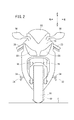
図1は、車速算出装置が搭載される自動二輪車10の側面図、図2は、図1に示す自動二輪車10の正面図である。なお、特に指示のない限り、図1及び図2において示す矢印方向に従って、前後、上下、左右の方向を説明する。
FIG. 1 is a side view of a
自動二輪車(車両)10は、車体フレーム12と、車体フレーム12の前端部に設けられたヘッドパイプ14と、ヘッドパイプ14に回転可能に軸支される左右一対のフロントフォーク16と、左右一対のフロントフォーク16に回転可能に軸支される操舵輪である前輪(車輪)18と、左右一対のフロントフォーク16の上部に取り付けられる操舵可能なバー状のハンドル20とを有する。
A motorcycle (vehicle) 10 includes a
車体フレーム12は、ヘッドパイプ14から後方に延びる左右一対のメインフレーム22と、左右一対のメインフレーム22の後側に設けられる左右一対のピボットプレート24と、左右一対のピボットプレート24に設けられ、後方斜め上方に延びる左右一対のシートフレーム26とを備える。左右一対のメインフレーム22には、動力を発生する動力ユニット28が設けられている。後端部で駆動輪である後輪(車輪)30を回転可能に軸支するスイングアーム32は、ピボットプレート24のスイングアームピボット軸(ピボット軸)25によって上下揺動可能に支持される。動力ユニット28は、そのケース内に原動機としてのエンジン28aと変速機28bとを収納する。なお、スイングアームピボット軸25は、エンジン28a又は動力ユニット28に設けられていてもよい。
The
エンジン28aの主軸としてのクランクシャフト29の駆動力(回転力)は、変速機28bのメインシャフト31aに伝達された後、カウンタシャフト31bから出力される。このカウンタシャフト31bから出力される駆動力は、チェーン33を介して後輪30に伝達される。
The driving force (rotational force) of the
ピボットプレート24には、運転者の脚を乗せる左右一対のステップ34が取り付けられ、ステップ34には、自動二輪車10の最大バンク角θmaxを設定するバンクセンサ38が設けられている。図6に示すように、自動二輪車10が、最大バンク角θmaxまでバンクすると、バンクセンサ38が路面Gに当接し、それ以上バンク角(ロール角)θが大きくならないように規制する。なお、自動二輪車10の左側の最大バンク角をθLmaxで表し、右側の最大バンク角をθRmaxで表し、この最大バンク角θLmax、θRmaxを総称して最大バンク角θmaxと呼ぶ。
A pair of left and
左右一対のメインフレーム22の上方には、燃料を貯留する燃料タンク40が設けられ、燃料タンク40の後方且つ、左右一対のシートフレーム26の上方には、運転者が着座する運転者用シート42が設けられ、運転者用シート42の後方には乗員が着座する乗員用シート44が設けられている。左右一対のフロントフォーク16には、フロントフェンダ46が設けられ、左右一対のシートフレーム26の後部には、リアフェンダ48が設けられている。このリアフェンダ48は、リアウインカ50を支持する。
A
自動二輪車10は、車体フレーム12に設けられ、前方を保護するアッパーカウル52と、アッパーカウル52の上方に設けられたウインドスクリーン54と、アッパーカウル52の上部に設けられ運転者が後方を確認するためのバックミラー56と、アッパーカウル52の前部に設けられ前方を照射するヘッドライト58と、自動二輪車10の前方側部を保護するミドルカウル60と、このミドルカウル60の下部に設けられ車両後方に延びるアンダーカウル62と、シートフレーム26の上方に設けられシートフレーム26の上部から運転者用シート42の下部まで覆うサイドカバー64とを備える。バックミラー56は、フロントウインカが内蔵されている。
The
カメラ100は、動力ユニット28の下方に設けられ、動力ユニット28の下方から路面Gを撮影する。次に、車速算出装置を構成するカメラ(撮影手段)100の自動二輪車10への取付構造について説明する。
The
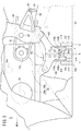
図3は、動力ユニット28の左側面から見た場合のカメラ100の取付構造を示す図、図4は、動力ユニット28の底面から見た場合のカメラ100の取付構造を示す図、図5は、図3のV−V線矢視断面図である。なお、説明を簡単にするため、必要のない構成要素を一部省略して図示している。
3 is a diagram showing the mounting structure of the
図3に示すように、カメラ100は、動力ユニット28(エンジン28a)の下方で、クランクシャフト29の中心よりも後方且つスイングアームピボット軸25の前方の位置に配置されると共に、動力ユニット28(エンジン28a)の下部、及び、ピボットプレート24の下部に固定支持されている。詳しくは、動力ユニット28の下部及びピボットプレート24の下部で懸架されたステー102にカメラ100が取り付けられている。なお、カメラ100は、エンジン28aの下部及びピボットプレート24の下部の少なくとも一方に固定支持されていればよく、カメラ100は、スイングアーム32の下方に設けられていてもよい。
As shown in FIG. 3, the
エンジン28aは、クランクシャフト29の下方に、下方に向けて膨出(突出)するように形成されたオイルパン104を備え、オイルパン104の後方に設けられた凹部105にカメラ100及びステー102が設けられている。この凹部105は、下方に膨出したオイルパン104によって形成される。
The
カメラ100の下部中央には、撮像素子100a(図9参照)に被写体の像を結像するためのレンズ106a(図9参照)を有する鏡筒106が取り付けられている。このレンズ106aの光軸がカメラ100の光軸oとなる。カメラ100の光軸oは、自動二輪車10が平らな路面Gに対して直立している時に、路面Gに対して略垂直となるように設計されていることが好ましい。カメラ100には、基準距離用マーク照射手段108と、第2マーク照射手段110とが取り付けられている。
At the lower center of the
基準距離用マーク照射手段108は、前後方向の基準距離T1[mm](例えば、90mm)を持つように形成された基準距離用マークを、カメラ100の光軸oと平行(側面視及び前面視でカメラ100の光軸oと平行)に路面Gに対して照射する。基準距離用マーク照射手段108は、カメラ100の撮影領域内に基準距離用マークを照射するように、カメラ100の前後に取り付けられている。
The reference distance mark irradiating means 108 is arranged so that the reference distance mark formed so as to have a reference distance T 1 [mm] (for example, 90 mm) in the front-rear direction is parallel to the optical axis o of the camera 100 (side view and front surface). The road surface G is irradiated in parallel to the optical axis o of the
基準距離用マーク照射手段108は、レーザ光を照射する前後方向に配置された2つのレーザポインター108a、108bを有する。この2つのレーザポインター108a、108bは、カメラ100の光軸oに対して前後に設けられ、その軸線(光軸)が前後方向に並ぶように配置されている。
The reference distance mark irradiating means 108 has two
本実施の形態では、2つのレーザポインター108a、108bの軸線を結ぶ線上に、カメラ100の光軸oが位置する。つまり、2つのレーザポインター108a、108bは、その軸線がカメラ100の光軸oとも前後方向に並ぶように配置されている(図4参照)。この2つのレーザポインター108a、108bは、前後方向に基準距離T1離れて配置されているので、前後方向に基準距離T1を持つように形成された2つの点、即ち基準距離用マークが路面Gに照射される。
In the present embodiment, the optical axis o of the
第2マーク照射手段110は、前後方向の所定距離T2[mm](例えば、70mm)を持つように形成された第2のマークを、カメラ100の光軸oと平行(側面視及び前面視でカメラ100の光軸oと平行)に路面Gに対して照射する。第2マーク照射手段110は、カメラ100の撮影領域内に第2のマークを照射するように、カメラ100の左側面に取り付けられている。
The second
第2マーク照射手段110は、レーザ光を照射する前後方向に配置された2つのレーザポインター110a、110bを有する。この2つのレーザポインター110a、110bは、カメラ100の光軸oに対して前後に設けられ、その軸線(光軸)が前後方向に並ぶように配置されている(図4参照)。第2マーク照射手段110は、基準距離用マーク照射手段108に対して左方向に距離(オフセット距離)D1(例えば、35mm)だけオフセットして配置されている。この2つのレーザポインター110a、110bは、前後方向に所定距離T2離れて配置されているので、前後方向に所定距離T2を持つように形成された2つの点(第2のマーク)が路面Gに照射される。
The second mark irradiation means 110 includes two
図3及び図5に示すように、カメラ100、基準距離用マーク照射手段108、及び第2マーク照射手段110は、動力ユニット28の下方を覆うアンダーカウル62内に収容される。アンダーカウル62には、カメラ100の光軸oに対応する位置に設けられた撮影用の開口112と、基準距離用マーク照射手段108の光軸に対応する位置に設けられた照射用の開口114と、第2マーク照射手段110の光軸に対応する位置に設けられた照射用の開口116がそれぞれ形成されている。この開口112、114、116により、カメラ100による撮影、基準距離用マーク照射手段108及び第2マーク照射手段110による照射が、アンダーカウル62によって妨げられることはない。これらの開口112、114、116は独立して開けられているが、それぞれが繋がっていてもよい。
As shown in FIGS. 3 and 5, the
図4に示すように、カメラ100は、光軸oが車幅中心線cより左側に距離(オフセット距離)D2(例えば、35mm)だけオフセットした位置に配置され、第2マーク照射手段110は、カメラ100の左側に配置されている。このオフセット距離D2が小さい程、カメラ100の光軸oを車幅中心線cに近づけることができるので、オフセット距離D2は、小さい程好ましく、0が最も好ましい。また、図4に示すように、オイルパン104は、動力ユニット28の右側寄りに設けられている。従って、エンジン28aの排気ガスを排出する排気管118は、オイルパン104の左側を通った後、右側に屈曲して、カメラ100の右側を通るように配置されている。このように、カメラ100の排気管118が設けられていない側に第2マーク照射手段110を取り付けたので、カメラ100の光軸oを車幅中心側に近づけることができる。なお、排気管118もアンダーカウル62内に設けられている。
As shown in FIG. 4, the
次に、カメラ100の画角について説明する。図6は、図2の要部拡大図である。カメラ100の車幅方向の画角(以下、車幅画角)αは、αmin≦α<αmaxの範囲で設定されることが望ましい。αminは、車両正面視で自動二輪車10が最大バンク角θmaxまでバンクした時の後輪30の路面Gとの接地点(後輪接地点)JL、JRが、正面視にてカメラ100の画角内に入る角度である。αmaxは、αmax=(90°−最大バンク角θmax)×2、で表される角度である。カメラ100の車幅画角αが、αmaxの場合は、自動二輪車10が最大バンク角θmaxまで傾いた際は、カメラ100の車幅画角αの一辺が路面Gと略平行となり、地平線(水平線)を撮影することになる。従って、車幅画角αを角度αmax未満にすることで、撮影領域が地平線よりも上にならず(撮影画像内に地平線より上方が写らず)、路面Gを多く撮影することができる。
Next, the angle of view of the
ここで、カメラ100の車幅画角αを、αmin以上、且つ、αmax未満の範囲内で設定した理由について説明する。カメラ100によって、自動二輪車10の下方の路面Gを撮影する場合に、路面状況の確認等を考慮すると、できるだけ実際に車輪、特に後輪30が通るであろう路面を撮影しておきたいという要望がある。また、自動二輪車10の場合は、バンク角θによってタイヤの接地点が変わるため、少なくとも左右の最大バンク時の後輪接地点JL、JRが両方入る程度の車幅画角αを確保しておきたい。
Here, the reason why the vehicle width angle of view α of the
一方、無用に車幅画角αを広げて撮影範囲を広げると、路面G以外の画像情報を無用に取得することになり、効率的ではない。特にバンク中では、後輪接地点が左右一方側に移動し、撮影画像の中心は、後輪30が通るであろう路面上の接地点から離間する方向(他方側)へ移動するので、実際に見たい後輪接地点JL、JR近傍の範囲が、撮影画像中の極一部に限られてしまう。従って、カメラ100の車幅画角αは、車両正面視で最大バンク時の後輪接地点JL、JRが入るのであれば車幅画角αはできるだけ小さい方がよい。このような観点から、カメラ100の車幅画角αは、αmin≦α<αmaxの関係を有することとした。
On the other hand, if the vehicle width angle of view α is unnecessarily widened to widen the shooting range, image information other than the road surface G is unnecessarily acquired, which is not efficient. Particularly in the bank, the rear wheel ground contact point moves to the left and right sides, and the center of the captured image moves in a direction away from the ground contact point on the road surface on which the
また、カメラ100の画角をできるだけ小さくして、且つ、必要な撮影幅を確保する場合、カメラ100の焦点ができるだけ上方に配置される必要がある。従って、本実施の形態では、スイングアームピボット軸25よりも前方で、オイルパン104の後方の凹部105にカメラ100を配置するので、カメラ100を可能な限り上方に配置することができ、上記したカメラ100の車幅画角αの条件を満たすことができる。
Further, in order to make the angle of view of the
なお、図6から諒解されるように、光軸oは、少なくとも後輪30のタイヤ幅内に配置されるのがよく、カメラ100、基準距離用マーク照射手段108、及び第2マーク照射手段110は、後輪30のタイヤ幅より内側の位置に設けられることが望ましい。また、少なくともカメラ100及び基準距離用マーク照射手段108は、前輪18のタイヤ幅より内側の位置に設けられることが望ましい。
As can be understood from FIG. 6, the optical axis o is preferably arranged at least within the tire width of the
このように、カメラ100をエンジン28a又はスイングアーム32の下方に配置したので、路面撮影の障害となる部品が少ない位置にカメラ100を配置することができる。また、カメラ100を、少なくともエンジン28a及び車体フレーム12を構成するピボットプレート24の少なくとも一方で支持し、振動を主に発生するクランクシャフト29の中心よりも後方に配置したので、振動の影響を受けにくい場所にカメラ100を配置でき、より鮮明な画像を撮影しやすい。
Thus, since the
カメラ100をスイングアームピボット軸25よりも前方に配置したので、上下に振動するスイングアーム32との干渉を避けてカメラ100を配置することができる。また、カメラ100は、オイルパン104の後方に設けられる凹部105に配置されるので、オイルパン104の容量確保と、カメラ100の配置スペースの確保とを両立することができる。
Since the
カメラ100は、アンダーカウル62の中に収容されるので、空気抵抗の抑制や水、埃等からカメラ100を保護することができると共に、外観性の向上を図ることができる。特に、カメラ100やレーザポインター108a、108b、110a、110bがアンダーカウル62の表面より内部に入っていれば、空気抵抗の抑制や埃よけの面でより有利である。また、カメラ100は、自動二輪車10が最もバンクした時においても、その撮影画像内に地平線より上方が写らない車幅画角αに設定されるので、路面G以外の映像が入るのを極力抑えることができる。
Since the
カメラ100は、車両正面視にて、自動二輪車10が最もバンクした時の後輪接地点JL、JRが正面視にてカメラ100の画角内に入るように車幅画角αが設定されるので、後輪30が通るであろう路面Gを、バンク角θによらず常に撮影することができる。
The
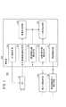
図7は、車速算出装置200の機能ブロック図である。車速算出装置200は、カメラ100、基準距離用マーク照射手段108、第2マーク照射手段110、及び制御部202を備える。制御部202は、カメラ制御手段210、照射制御手段212、移動距離検出手段214、画像基準距離検出手段216、車速算出手段218、画像所定距離検出手段220、及びバンク角算出手段222を有する。この制御部202は、CPU及びメモリ等を有するコンピュータであり、前記CPUが前記メモリに記憶されたプログラムを読み込むことによって、本実施の形態の制御部202として機能する。
FIG. 7 is a functional block diagram of the vehicle
カメラ制御手段210は、カメラ100の撮影を制御する。カメラ制御手段210は、自動二輪車10が走行中の場合は、所定の周期(フレームレート)(例えば、500fps)で路面Gを撮影するように、カメラ100を制御する。照射制御手段212は、基準距離用マーク照射手段108及び第2マーク照射手段110の照射を制御する。照射制御手段212は、自動二輪車10が走行中の場合は、基準距離用マーク照射手段108及び第2マーク照射手段110が路面Gに光を照射するように制御する。このとき、照射制御手段212は、カメラ100の露光期間中に光を照射し、露光期間以外の期間には、光の照射を中止するように、基準距離用マーク照射手段108及び第2マーク照射手段110を制御してもよい。
The
移動距離検出手段214は、カメラ100が撮影した撮影領域内の特徴点pが、撮影画像中で単位時間当たり(例えば、1秒当たり)に移動した移動距離x[pixel/sec]を検出する。つまり、前回撮影した撮影画像(前回撮影画像)内にある特徴点pが次に撮影した撮影画像(今回撮影画像)のどこにあるのかを、ブロックマッチング法や、代表点マッチング法等を用いて検出することで、該特徴点pの単位時間当たりの移動距離xを検出する。
The moving
ここで、特徴点pは、路面G上にある模様、凹凸の陰影等から抽出される点である。また、この移動距離xは、あくまで撮影画像中における移動距離xであるので、同じ車速v[mm/sec]であっても、自動二輪車10の車高(つまり、カメラ100の路面Gに対する高さ)によってその値は変わってしまう。例えば、同じ車速vであっても車高が高い場合は、低い場合に比べ移動距離xは小さくなってしまう。なお、図8に示す撮影画像には、1/500秒当たり移動距離x´を図示している。
Here, the feature point p is a point extracted from a pattern on the road surface G, a shade of unevenness, or the like. Further, since the moving distance x is only the moving distance x in the photographed image, the vehicle height of the motorcycle 10 (that is, the height of the
画像基準距離検出手段216は、基準距離用マーク照射手段108によって照射された基準距離用マークの撮影画像中における前後方向の長さである画像基準距離Y1[pixel]を検出する。この撮影画像中における前後方向は、自動二輪車10の前後方向と同じ方向である。この画像基準距離Y1は、撮影画像中における基準距離T1を表しているので、自動二輪車10の車高によってその値は変わってしまう。例えば、同じ車速vであっても車高が高い場合は、低い場合に比べ画像基準距離Y1は小さくなってしまう。なお、図8に示す撮影画像に、この画像基準距離Y1を図示している。なお、図8中の参照符号109は、撮影画像中における基準距離用マークを表している。基準距離用マーク109は、点109a及び点109bによって構成される。
The image reference
この点109a及び点109bは、光軸oから等距離の位置にあると尚よい。つまり、レーザポインター108a、108bが、光軸oから等距離の位置で光軸oと平行に光を照射するように、設けられることが好ましい。この光軸oは、撮影画像の中心にある。なお、図8においては、撮影画像の中心(光軸o)から撮影画像の前後方向に延びた直線hと、撮影画像の中心から撮影画像の左右方向に延びた直線iを便宜的に図示している。基準距離用マーク109の点109a、109bは、この直線h上にある。
It is more preferable that the
車速算出手段218は、移動距離検出手段214が検出した移動距離xから車速v[mm/sec]を算出する。ここで、移動距離xは、車速vが同一でも車高に応じて変わり、四輪自動車等に比べ、加減速やバンクをすることで車高が変化しやすい自動二輪車10では尚更である。従って、車高が変化しても車速vの精度を向上させるべく、車速算出手段218は、画像基準距離検出手段216が検出した画像基準距離Y1と、基準距離用マーク109の基準距離T1とを用いて、移動距離検出手段214が検出した単位時間当たりの移動距離xから車速vを算出する。詳しくは、以下の数式(1)を用いて車速vを算出する。
The vehicle speed calculation means 218 calculates the vehicle speed v [mm / sec] from the movement distance x detected by the movement distance detection means 214. Here, the moving distance x changes according to the vehicle height even if the vehicle speed v is the same, and is even more so in the

画像所定距離検出手段220は、第2マーク照射手段110によって照射された第2のマークの撮影画像中における前後方向の長さである画像所定距離Y2[pixel]を検出する。この画像所定距離Y2は、撮影画像中における所定距離T2を表しているので、自動二輪車10の車高やバンク角θによってその値は変わってしまう。例えば、同じ車速vであっても車高が高い場合は、低い場合に比べ画像所定距離Y2は小さくなってしまう。なお、図8に示す撮影画像に、この画像所定距離Y2を図示している。また、図8に示すNは、撮影画像の前後方向の距離[pixel]を表し、Mは、撮影画像の左右方向の距離[pixel]を表している。
The predetermined image
なお、図8中の参照符号111は、撮影画像中における第2のマークを表している。第2のマーク111は、点111a及び点111bによって構成される。この点111a及び点111bは、光軸oから等距離の位置にあると尚よい。つまり、レーザポインター110a、110bが、光軸oから等距離の位置で光軸oと平行に光を照射するように、設けられることが好ましい。また、図8に示すNは、長い方が好ましいが前輪18及び後輪30が入らないように設定することが望ましい。
Note that
バンク角算出手段222は、基準距離T1、所定距離T2、画像基準距離検出手段216が検出した画像基準距離Y1、及び、画像所定距離検出手段220が検出した画像所定距離Y2に基づいて、自動二輪車10のバンク角θを算出する。自動二輪車10のバンク角θの算出方法を、図9及び図10を用いて説明する。なお、図9は、自動二輪車10の左側面から視たカメラ100、基準距離用マーク照射手段108、及び第2マーク照射手段110を示しており、図10は、自動二輪車10の正面から視たカメラ100、基準距離用マーク照射手段108、及び第2マーク照射手段110を示している。
The bank angle calculation means 222 is based on the reference distance T 1 , the predetermined distance T 2 , the image reference distance Y 1 detected by the image reference distance detection means 216, and the image predetermined distance Y 2 detected by the image predetermined distance detection means 220. Thus, the bank angle θ of the
まず、バンク角算出手段222は、図9に示す画像基準距離Y1に基づく実際の撮影範囲の距離(以下、実撮影範囲幅という)W1[mm]と、画像所定距離Y2に基づく実撮影範囲幅W2[mm]とを算出する。詳しくは、下記の数式(2)を用いて実撮影範囲幅W1を算出し、数式(3)を用いて実撮影範囲幅W2を算出する。 First, the bank angle calculation means 222, the distance of the actual photography range based on the image reference distance Y 1 shown in FIG. 9 (hereinafter, actual photography range width hereinafter) and W 1 [mm], the real based on the image a predetermined distance Y 2 An imaging range width W 2 [mm] is calculated. Specifically, the actual shooting range width W 1 is calculated using the following formula (2), and the actual shooting range width W 2 is calculated using the formula (3).
バンク角算出手段222は、算出した実撮影範囲幅W1に基づいてカメラ100の光軸oと路面Gとの交点qからレンズ106a中心までの距離L1[mm](図9参照)を、下記の数式(4)を用いて算出する。また、バンク角算出手段222は、算出した実撮影範囲幅W2に基づいて、カメラ100の光軸oと路面Gとの交点qからレンズ106a中心までの距離L2[mm](図9参照)を下記の数式(5)を用いて算出する。なお、図9においてはカメラ100の前後方向の画角(前後画角)をβで表している。
The bank angle calculation means 222 calculates a distance L 1 [mm] (see FIG. 9) from the intersection q between the optical axis o of the
バンク角算出手段222は、算出した距離L1、L2と、基準距離用マーク照射手段108と第2マーク照射手段110とのオフセット距離D1とを用いて、図10に示すバンク角θを算出する。詳しくは、下記の数式(6)を用いてバンク角θを算出する。 The bank angle calculation means 222 calculates the bank angle θ shown in FIG. 10 using the calculated distances L 1 and L 2 and the offset distance D1 between the reference distance mark irradiation means 108 and the second mark irradiation means 110. To do. Specifically, the bank angle θ is calculated using the following formula (6).
この車速算出装置200が算出した車速v及びバンク角θを用いて、トラクションコントロールや、ABS制御等に用いられる。
Using the vehicle speed v and the bank angle θ calculated by the vehicle
このように、上記実施の形態によれば、路面Gを撮影するカメラ100の光軸oと平行に、前後方向に基準距離T1を持つように形成された基準距離用マーク109をカメラ100の撮影領域内で路面Gに照射するので、撮影画像中に実距離の指標となるマークを投影することができ、車高が変化した場合であっても、精度よく自動二輪車10の車速vを求めることができる。
Thus, according to the above embodiment, the
基準距離用マーク照射手段108を構成する2つのレーザポインター108a、108bは、カメラ100の光軸oと平行に照射するものであって、それぞれ前後方向に離間して配置されるので、基準距離T1を保つようにカメラ100の光軸oに平行に光を照射する手段して、非常に精度がよく且つシンプルな基準距離用マーク照射手段108を構成することができる。また、2つのレーザポインター108a、108bは、カメラ100の光軸oに対して前後に設けられているので、基準距離T1を大きく確保し易く画像認識の誤差の影響を少なくすることができ、車速vの算出精度を向上させることができる。更に、2つのレーザポインター108a、108bは、その軸線がカメラ100の光軸oと前後方向に並ぶように配置されるので、自動二輪車10がバンクした時でも基準距離T1のバラツキが起こり難く、車速vの算出精度が向上する。
The two
また、撮影領域内で、且つ、基準距離用マーク109に対して少なくとも車両の左方向にオフセットした位置に第2のマーク111を路面Gに対して照射するので、自動二輪車10のバンク角θを求めることができる。第2のマーク111は、前後方向に所定距離T2を持つように形成され、第2マーク照射手段110は、カメラ100の光軸oと平行に第2のマーク111を照射するので、精度よく車両のバンク角θを求めることができる。
Further, since the
第2マーク照射手段110を構成する2つのレーザポインター110a、110bは、カメラ100の光軸oと平行に照射するものであって、それぞれ前後方向に離間して配置されるので、所定距離T2を保つようにカメラ100の光軸oに平行に光を照射する手段として、非常に精度がよく且つシンプルな第2マーク照射手段110を構成することができる。また、2つのレーザポインター110a、110bは、カメラ100の光軸oに対して前後に設けられているので、所定距離T2を大きく確保し易く画像認識の誤差の影響を少なくすることができ、自動二輪車10のバンク角θの算出精度を向上させることができる。更に、2つのレーザポインター110a、110bは、その軸線が前後方向に並ぶように配置されるので、自動二輪車10がバンクした時でも所定距離T2のバラツキが起こり難く、自動二輪車10のバンク角θの算出精度が向上する。
Two
基準距離用マーク照射手段108及び第2マーク照射手段110は、カメラ100に取り付けられるので、カメラ100の光軸oに対するレーザポインター108a、108b、110a、110bの光軸の平行度を高くでき、車速vの算出精度が向上する。
Since the reference distance mark irradiation means 108 and the second mark irradiation means 110 are attached to the
カメラ100は、少なくともエンジン28aの下方又は車体フレーム12の下方に配置され、第2マーク照射手段110は、カメラ100の一方側に配置され、排気管118がカメラ100の他方側を通るので、車速算出装置200の搭載によって自動二輪車10が大型化することがなく、カメラ100の光軸oを自動二輪車10の車幅方向の中心(車幅中心線c)に近づけて配置することができる。
Since the
なお、上記実施の形態においては、第2マーク照射手段110を、基準距離用マーク照射手段108に対して左方向に距離D1だけオフセットした位置に配置したが、第2マーク照射手段110を、基準距離用マーク照射手段108に対して右方向に距離D1だけオフセットした位置に配置してもよい。この場合は、排気管118をカメラ100の左側を通るようにすることで、カメラ100の光軸oを自動二輪車10の車幅中心線cに近づけることができる。
In the above embodiment, the second
光軸oが車幅中心線cより左側にオフセットした位置にカメラ100を配置するようにしたが、車幅中心線cより右側にオフセットした位置にカメラ100を配置するようにしてもよい。勿論、光軸oが車幅中心線cと一致するようにカメラ100を設けることが望ましい。
Although the
レーザポインター110a、110bを、基準距離用マーク照射手段108に対して左方向に距離D1だけオフセットした位置に配置したが、レーザポインター110a、110bをそれぞれ左右方向に距離D1だけオフセットした位置にそれぞれ配置してもよい。
The
上記実施の形態では、車速算出装置200を、エンジン28aの下方に設けるようにしたが、車体フレーム12の下方であればよい。また、自動二輪車10を用いて説明したが、揺動車両であれば、三輪自動車、四輪自動車等であってもよい。
In the above-described embodiment, the vehicle
バンク角算出手段222は、上記数式(2)〜(6)を用いて、バンク角θを算出するようにしたが、以下の手法によってバンク角θを算出してもよい。この場合は、画像所定距離検出手段220は、基準距離用マーク照射手段108によって照射された基準距離用マーク109及び第2マーク照射手段110によって照射された第2のマーク111の撮影画像中におけるオフセット距離(車幅方向における距離)Y3[pixel]を検出する(図8参照)。そして、バンク角算出手段222は、オフセット距離D1と基準距離T1との比率(D1/T1)と、オフセット距離Y3と画像基準距離Y1との比率(Y3/Y1)とによってバンク角θを求める。
Although the bank
上記実施の形態では、エンジン28aを用いて説明したが、揺動車両の駆動源となる原動機であればよく、原動機として電動モータを用いてもよい。この場合は、電動モータのロータと一体的に回転する回転軸が主軸となる。
Although the
以上、本発明について好適な実施の形態を用いて説明したが、本発明の技術的範囲は上記実施の形態の記載の範囲には限定されない。上記実施の形態に、多様な変更又は改良を加えることが可能であることが当業者に明らかである。その様な変更又は改良を加えた形態も本発明の技術的範囲に含まれ得ることが、特許請求の範囲の記載から明らかである。また、特許請求の範囲に記載された括弧書きの符号は、本発明の理解の容易化のために添付図面中の符号に倣って付したものであり、本発明がその符号をつけた要素に限定されて解釈されるものではない。 As mentioned above, although this invention was demonstrated using suitable embodiment, the technical scope of this invention is not limited to the range of description of the said embodiment. It will be apparent to those skilled in the art that various modifications or improvements can be added to the above embodiment. It is apparent from the description of the scope of claims that embodiments with such changes or improvements can be included in the technical scope of the present invention. In addition, the reference numerals in parentheses described in the claims are appended to the reference numerals in the accompanying drawings for easy understanding of the present invention. It should not be construed as limited.
10…自動二輪車 12…車体フレーム
14…ヘッドパイプ 18…前輪
20…ハンドル 25…スイングアームピボット軸
28…動力ユニット 28a…エンジン
28b…変速機 29…クランクシャフト
30…後輪 32…スイングアーム
34…ステップ 38…バンクセンサ
62…アンダーカウル 100…カメラ
102…ステー 104…オイルパン
105…凹部 106…鏡筒
108…基準距離用マーク照射手段
108a、108b、110a、110b…レーザポインター
109…基準距離用マーク 110…第2マーク照射手段
111…第2のマーク 112、114、116…開口
118…排気管 200…車速算出装置
202…制御部 210…カメラ制御手段
212…照射制御手段 214…移動距離検出手段
216…画像基準距離検出手段 218…車速算出手段
220…画像所定距離検出手段 222…バンク角算出手段
DESCRIPTION OF
Claims (13)
前記撮影手段(100)によって撮影された撮影領域内の特徴点(p)が、撮影画像中で単位時間当たりに移動した移動距離(x)を検出する移動距離検出手段(214)と、
前記移動距離検出手段(214)によって検出された前記移動距離(x)から前記車両(10)の前記路面に対する車速(v)を算出する車速算出手段(218)と、
を備える車速算出装置(200)において、
前記撮影領域内で前記車両(10)の前後方向の基準距離(T1)を持つように形成された基準距離用マーク(109)を、前記撮影手段(100)の光軸(o)と平行に前記路面に対して照射する基準距離用マーク照射手段(108)と、
前記基準距離用マーク照射手段(108)によって照射された前記基準距離用マーク(109)の前記撮影画像中における前記前後方向の長さである画像基準距離(Y1)を検出する画像基準距離検出手段(216)と、
を有し、
前記車速算出手段(218)は、前記基準距離(T1)と前記画像基準距離検出手段(216)によって検出された前記画像基準距離(Y1)とを用いて前記移動距離(x)から前記車速(v)を算出する
ことを特徴とする車速算出装置(200)。 Photographing means (100) attached to the vehicle (10) and photographing a road surface;
A moving distance detecting means (214) for detecting a moving distance (x) in which the feature point (p) in the shooting area shot by the shooting means (100) has moved per unit time in the shot image;
Vehicle speed calculation means (218) for calculating a vehicle speed (v) of the vehicle (10) relative to the road surface from the movement distance (x) detected by the movement distance detection means (214);
In a vehicle speed calculation device (200) comprising:
A reference distance mark (109) formed so as to have a reference distance (T 1 ) in the front-rear direction of the vehicle (10) within the imaging region is parallel to the optical axis (o) of the imaging means (100). A reference distance mark irradiating means (108) for irradiating the road surface with
Image reference distance detection for detecting an image reference distance (Y 1 ) which is the length in the front-rear direction in the captured image of the reference distance mark (109) irradiated by the reference distance mark irradiation means (108). Means (216);
Have
The vehicle speed calculation means (218) uses the reference distance (T 1 ) and the image reference distance (Y 1 ) detected by the image reference distance detection means (216) to calculate the vehicle speed from the movement distance (x). A vehicle speed calculation device (200) characterized by calculating a vehicle speed (v).
前記基準距離用マーク照射手段(108)は、前記撮影手段(100)の光軸(o)と平行に照射するものであって、それぞれ前記前後方向に離間して配置される2つのレーザポインター(108a、108b)で構成される
ことを特徴とする車速算出装置(200)。 In the vehicle speed calculation device (200) according to claim 1,
The reference distance mark irradiating means (108) irradiates in parallel with the optical axis (o) of the photographing means (100), and two laser pointers (2) spaced apart in the front-rear direction are provided. 108a, 108b). A vehicle speed calculation device (200) characterized by comprising:
前記基準距離用マーク照射手段(108)を構成する前記2つのレーザポインター(108a、108b)は、前記撮影手段(100)の光軸(o)に対して前後に設けられている
ことを特徴とする車速算出装置(200)。 In the vehicle speed calculation device (200) according to claim 2,
The two laser pointers (108a, 108b) constituting the reference distance mark irradiating means (108) are provided in front of and behind the optical axis (o) of the photographing means (100). A vehicle speed calculation device (200).
前記基準距離用マーク照射手段(108)を構成する前記2つのレーザポインター(108a、108b)は、その光軸が前記前後方向に並ぶように配置される
ことを特徴とする車速算出装置(200)。 In the vehicle speed calculation device (200) according to claim 2 or 3,
The vehicle speed calculation device (200), wherein the two laser pointers (108a, 108b) constituting the reference distance mark irradiating means (108) are arranged so that their optical axes are aligned in the front-rear direction. .
前記基準距離用マーク照射手段(108)を構成する前記2つのレーザポインター(108a、108b)は、その光軸が前記撮影手段(100)の光軸(o)とも前記前後方向に並ぶように配置される
ことを特徴とする車速算出装置(200)。 In the vehicle speed calculation device (200) according to claim 4,
The two laser pointers (108a, 108b) constituting the reference distance mark irradiating means (108) are arranged so that their optical axes are aligned with the optical axis (o) of the photographing means (100) in the front-rear direction. A vehicle speed calculation device (200) characterized in that:
前記基準距離用マーク照射手段(108)は、前記撮影手段(100)に取り付けられる
ことを特徴とする車速算出装置(200)。 In the vehicle speed calculation device (200) according to any one of claims 1 to 5,
The vehicle speed calculation device (200), wherein the reference distance mark irradiating means (108) is attached to the photographing means (100).
前記撮影領域内で、且つ、前記基準距離用マーク(109)に対して少なくとも前記車両(10)の左右方向にオフセットした位置に第2のマーク(111)を前記路面に対して照射する第2マーク照射手段(110)を備える
ことを特徴とする車速算出装置(200)。 In the vehicle speed calculation device (200) according to any one of claims 1 to 6,
A second mark (111) that irradiates the road surface with a second mark (111) at a position offset in the left-right direction of the vehicle (10) at least in the left-right direction with respect to the reference distance mark (109) within the imaging region. A vehicle speed calculation device (200) comprising a mark irradiation means (110).
前記第2のマーク(111)は、少なくとも前記左右方向にオフセットした位置に、前記前後方向に所定距離(T2)を持つように形成され、
前記第2マーク照射手段(110)は、前記撮影手段(100)の光軸(o)と平行に前記第2のマーク(111)を照射する
ことを特徴とする車速算出装置(200)。 In the vehicle speed calculation device (200) according to claim 7,
The second mark (111) is formed at a position offset at least in the left-right direction so as to have a predetermined distance (T 2 ) in the front-rear direction,
The vehicle speed calculation device (200), wherein the second mark irradiating means (110) irradiates the second mark (111) in parallel with the optical axis (o) of the photographing means (100).
前記第2マーク照射手段(110)は、前記撮影手段(100)の光軸(o)と平行に照射するものであって、それぞれ前記前後方向に離間して配置される2つのレーザポインター(110a、110b)で構成される
ことを特徴とする車速算出装置(200)。 In the vehicle speed calculation device (200) according to claim 7 or 8,
The second mark irradiating means (110) irradiates in parallel with the optical axis (o) of the photographing means (100), and is provided with two laser pointers (110a) spaced apart in the front-rear direction. 110b), a vehicle speed calculation device (200).
前記第2マーク照射手段(110)を構成する前記2つのレーザポインター(110a、110b)は、前記撮影手段(100)の光軸(o)に対して前後に設けられている
ことを特徴とする車速算出装置(200)。 In the vehicle speed calculation device (200) according to claim 9,
The two laser pointers (110a, 110b) constituting the second mark irradiating means (110) are provided in front of and behind the optical axis (o) of the photographing means (100). Vehicle speed calculation device (200).
前記第2マーク照射手段(110)を構成する前記2つのレーザポインター(110a、110b)は、その光軸が前記前後方向に並ぶように配置される
ことを特徴とする車速算出装置(200)。 In the vehicle speed calculation device (200) according to claim 9 or 10,
The vehicle speed calculation device (200), wherein the two laser pointers (110a, 110b) constituting the second mark irradiating means (110) are arranged so that their optical axes are aligned in the front-rear direction.
前記第2マーク照射手段(110)は、前記撮影手段(100)に取り付けられる
ことを特徴とする車速算出装置(200)。 In the vehicle speed calculation device (200) according to any one of claims 7 to 11,
The vehicle speed calculation device (200), wherein the second mark irradiating means (110) is attached to the photographing means (100).
前記車両(10)は、自動二輪車であって、
前記撮影手段(100)は、少なくともエンジン(28a)の下方又は車体フレーム(12)の下方に配置され、
前記第2マーク照射手段(110)は、前記撮影手段(100)の一方側に配置され、排気管(118)が前記撮影手段(100)の他方側を通る
ことを特徴とする車速算出装置(200)。 In the vehicle speed calculation device (200) according to any one of claims 7 to 12,
The vehicle (10) is a motorcycle,
The photographing means (100) is disposed at least below the engine (28a) or below the vehicle body frame (12),
The second mark irradiating means (110) is disposed on one side of the photographing means (100), and an exhaust pipe (118) passes through the other side of the photographing means (100). 200).
Priority Applications (4)
| Application Number | Priority Date | Filing Date | Title |
|---|---|---|---|
| JP2013017647A JP6140463B2 (en) | 2013-01-31 | 2013-01-31 | Vehicle speed calculation device |
| US14/156,630 US9256952B2 (en) | 2013-01-31 | 2014-01-16 | Vehicle speed calculator, and vehicle including same |
| ES14153100.4T ES2544129T3 (en) | 2013-01-31 | 2014-01-29 | Vehicle speed calculator |
| EP14153100.4A EP2762892B1 (en) | 2013-01-31 | 2014-01-29 | Vehicle speed calculator |
Applications Claiming Priority (1)
| Application Number | Priority Date | Filing Date | Title |
|---|---|---|---|
| JP2013017647A JP6140463B2 (en) | 2013-01-31 | 2013-01-31 | Vehicle speed calculation device |
Publications (2)
| Publication Number | Publication Date |
|---|---|
| JP2014149209A JP2014149209A (en) | 2014-08-21 |
| JP6140463B2 true JP6140463B2 (en) | 2017-05-31 |
Family
ID=50002617
Family Applications (1)
| Application Number | Title | Priority Date | Filing Date |
|---|---|---|---|
| JP2013017647A Expired - Fee Related JP6140463B2 (en) | 2013-01-31 | 2013-01-31 | Vehicle speed calculation device |
Country Status (4)
| Country | Link |
|---|---|
| US (1) | US9256952B2 (en) |
| EP (1) | EP2762892B1 (en) |
| JP (1) | JP6140463B2 (en) |
| ES (1) | ES2544129T3 (en) |
Families Citing this family (9)
| Publication number | Priority date | Publication date | Assignee | Title |
|---|---|---|---|---|
| JP5938057B2 (en) * | 2014-03-28 | 2016-06-22 | 株式会社ショーワ | Vehicle height adjustment device, control device for vehicle height adjustment device, and program |
| WO2017057052A1 (en) | 2015-09-30 | 2017-04-06 | ソニー株式会社 | Information processing device, information processing method, and program |
| US9840239B2 (en) * | 2015-10-13 | 2017-12-12 | Robert Bosch Gmbh | Cornering brake control |
| DE102017201574A1 (en) | 2017-02-01 | 2018-08-02 | Bayerische Motoren Werke Aktiengesellschaft | Package compartment for holding parcels, motor vehicle and method for delivering a parcel |
| JP6894416B2 (en) * | 2018-09-27 | 2021-06-30 | 本田技研工業株式会社 | Saddle-type vehicle |
| DE102021208569A1 (en) * | 2021-08-06 | 2023-02-09 | Robert Bosch Gesellschaft mit beschränkter Haftung | Method for operating a vehicle assistance system for a motor vehicle, vehicle assistance system for a motor vehicle, motor vehicle |
| JP7548196B2 (en) | 2021-11-22 | 2024-09-10 | トヨタ自動車株式会社 | Image Display System |
| AT525694B1 (en) * | 2021-12-06 | 2024-09-15 | Avl List Gmbh | METHOD FOR DETERMINING THE SPEED AND/OR DIRECTION OF MOVEMENT OF A VEHICLE |
| EP4361680A3 (en) * | 2022-10-31 | 2024-06-19 | FERRARI S.p.A. | Motor vehicle and method to detect the driving speed of the motor vehicle itself |
Family Cites Families (9)
| Publication number | Priority date | Publication date | Assignee | Title |
|---|---|---|---|---|
| JPH0798225A (en) * | 1993-09-29 | 1995-04-11 | Koito Mfg Co Ltd | Inclination angle measuring instrument |
| JP3346189B2 (en) * | 1996-10-24 | 2002-11-18 | トヨタ自動車株式会社 | Vehicle momentum detection device |
| JP2007046949A (en) * | 2005-08-08 | 2007-02-22 | Sumitomo Electric Ind Ltd | Vehicle-mounted ground speed measuring apparatus and ground-speed measuring method |
| FR2893140B1 (en) * | 2005-11-04 | 2007-12-28 | Atmel Grenoble Soc Par Actions | GROUND SPEED SENSOR OF A VEHICLE |
| JP4780614B2 (en) * | 2006-04-10 | 2011-09-28 | アルパイン株式会社 | Body behavior measuring device |
| JP5057952B2 (en) * | 2007-12-06 | 2012-10-24 | アルパイン株式会社 | Angular velocity correction device, correction method thereof, and navigation device |
| CN102292646B (en) * | 2009-01-20 | 2014-03-12 | 皇家飞利浦电子股份有限公司 | Method for adjusting self mixing laser sensor system for measuring velocity of vehicle |
| KR101734354B1 (en) * | 2009-04-29 | 2017-05-11 | 코닌클리케 필립스 엔.브이. | A laser diode based multiple-beam laser spot imaging system for characterization of vehicle dynamics |
| US8724118B1 (en) * | 2012-11-28 | 2014-05-13 | Eastman Kodak Company | Mobile apparatus with local position referencing structure |
-
2013
- 2013-01-31 JP JP2013017647A patent/JP6140463B2/en not_active Expired - Fee Related
-
2014
- 2014-01-16 US US14/156,630 patent/US9256952B2/en active Active
- 2014-01-29 ES ES14153100.4T patent/ES2544129T3/en active Active
- 2014-01-29 EP EP14153100.4A patent/EP2762892B1/en not_active Not-in-force
Also Published As
| Publication number | Publication date |
|---|---|
| US9256952B2 (en) | 2016-02-09 |
| ES2544129T3 (en) | 2015-08-27 |
| JP2014149209A (en) | 2014-08-21 |
| US20140212003A1 (en) | 2014-07-31 |
| EP2762892B1 (en) | 2015-07-01 |
| EP2762892A1 (en) | 2014-08-06 |
Similar Documents
| Publication | Publication Date | Title |
|---|---|---|
| JP6140463B2 (en) | Vehicle speed calculation device | |
| JP6628411B2 (en) | Optical sensor arrangement structure for saddle type vehicle | |
| CN107878327B (en) | Periphery monitoring device | |
| JP6684903B2 (en) | Optical sensor support structure for saddle type vehicles | |
| KR101822890B1 (en) | Front Vedeo Camera for Vehicles | |
| JP5936288B2 (en) | Vehicle imaging device | |
| US7556410B2 (en) | Vehicle headlight device | |
| JP5947268B2 (en) | Roll angle estimation device for vehicle | |
| JP2009023543A (en) | Vehicle and driving support device of vehicle | |
| EP3369619B1 (en) | Lighting apparatus arrangement for saddle riding vehicle, and saddle riding vehicle | |
| JP2012136206A (en) | System and method for parking control | |
| JP6839119B2 (en) | Saddle-type vehicle | |
| JP6096522B2 (en) | Motorcycle | |
| US20160090139A1 (en) | Vehicle including steps | |
| JP6873070B2 (en) | Saddle-type vehicle lighting device layout structure | |
| EP2377006A1 (en) | Method of control and associated driving aid system | |
| JP2017039488A (en) | Lean vehicle | |
| JP2013147113A (en) | Road surface state detection device and suspension control device | |
| KR101377204B1 (en) | System and method of providing road surface information, and vehicle using the same | |
| JP7291232B2 (en) | Straddle-type vehicle, straddle-type vehicle control method and program | |
| JP2019073079A (en) | Vehicle structure | |
| JP2015018409A (en) | Drive recorder device for two-wheel vehicle | |
| JP6670882B2 (en) | Front cowl structure of saddle type vehicle | |
| WO2021064804A1 (en) | Estimation device and saddle-type vehicle | |
| JP2020139796A (en) | Vehicle state detection device and vehicle speed measurement device |
Legal Events
| Date | Code | Title | Description |
|---|---|---|---|
| A621 | Written request for application examination |
Free format text: JAPANESE INTERMEDIATE CODE: A621 Effective date: 20151126 |
|
| A977 | Report on retrieval |
Free format text: JAPANESE INTERMEDIATE CODE: A971007 Effective date: 20160810 |
|
| A131 | Notification of reasons for refusal |
Free format text: JAPANESE INTERMEDIATE CODE: A131 Effective date: 20161004 |
|
| A521 | Request for written amendment filed |
Free format text: JAPANESE INTERMEDIATE CODE: A523 Effective date: 20161129 |
|
| TRDD | Decision of grant or rejection written | ||
| A01 | Written decision to grant a patent or to grant a registration (utility model) |
Free format text: JAPANESE INTERMEDIATE CODE: A01 Effective date: 20170411 |
|
| A61 | First payment of annual fees (during grant procedure) |
Free format text: JAPANESE INTERMEDIATE CODE: A61 Effective date: 20170501 |
|
| R150 | Certificate of patent or registration of utility model |
Ref document number: 6140463 Country of ref document: JP Free format text: JAPANESE INTERMEDIATE CODE: R150 |
|
| LAPS | Cancellation because of no payment of annual fees |