WO2021060407A1 - 投映像表示用部材、ウインドシールドガラスおよびヘッドアップディスプレイシステム - Google Patents
投映像表示用部材、ウインドシールドガラスおよびヘッドアップディスプレイシステム Download PDFInfo
- Publication number
- WO2021060407A1 WO2021060407A1 PCT/JP2020/036123 JP2020036123W WO2021060407A1 WO 2021060407 A1 WO2021060407 A1 WO 2021060407A1 JP 2020036123 W JP2020036123 W JP 2020036123W WO 2021060407 A1 WO2021060407 A1 WO 2021060407A1
- Authority
- WO
- WIPO (PCT)
- Prior art keywords
- layer
- liquid crystal
- light
- image display
- display member
- Prior art date
- Legal status (The legal status is an assumption and is not a legal conclusion. Google has not performed a legal analysis and makes no representation as to the accuracy of the status listed.)
- Ceased
Links
Images


Classifications
-
- G—PHYSICS
- G02—OPTICS
- G02B—OPTICAL ELEMENTS, SYSTEMS OR APPARATUS
- G02B27/00—Optical systems or apparatus not provided for by any of the groups G02B1/00 - G02B26/00, G02B30/00
- G02B27/01—Head-up displays
- G02B27/0101—Head-up displays characterised by optical features
-
- G—PHYSICS
- G02—OPTICS
- G02B—OPTICAL ELEMENTS, SYSTEMS OR APPARATUS
- G02B5/00—Optical elements other than lenses
- G02B5/30—Polarising elements
- G02B5/3083—Birefringent or phase retarding elements
-
- B—PERFORMING OPERATIONS; TRANSPORTING
- B60—VEHICLES IN GENERAL
- B60R—VEHICLES, VEHICLE FITTINGS, OR VEHICLE PARTS, NOT OTHERWISE PROVIDED FOR
- B60R1/00—Optical viewing arrangements; Real-time viewing arrangements for drivers or passengers using optical image capturing systems, e.g. cameras or video systems specially adapted for use in or on vehicles
- B60R1/001—Optical viewing arrangements; Real-time viewing arrangements for drivers or passengers using optical image capturing systems, e.g. cameras or video systems specially adapted for use in or on vehicles integrated in the windows, e.g. Fresnel lenses
-
- G—PHYSICS
- G02—OPTICS
- G02B—OPTICAL ELEMENTS, SYSTEMS OR APPARATUS
- G02B5/00—Optical elements other than lenses
- G02B5/30—Polarising elements
- G02B5/3016—Polarising elements involving passive liquid crystal elements
-
- G—PHYSICS
- G02—OPTICS
- G02B—OPTICAL ELEMENTS, SYSTEMS OR APPARATUS
- G02B5/00—Optical elements other than lenses
- G02B5/30—Polarising elements
- G02B5/3025—Polarisers, i.e. arrangements capable of producing a definite output polarisation state from an unpolarised input state
-
- G—PHYSICS
- G02—OPTICS
- G02F—OPTICAL DEVICES OR ARRANGEMENTS FOR THE CONTROL OF LIGHT BY MODIFICATION OF THE OPTICAL PROPERTIES OF THE MEDIA OF THE ELEMENTS INVOLVED THEREIN; NON-LINEAR OPTICS; FREQUENCY-CHANGING OF LIGHT; OPTICAL LOGIC ELEMENTS; OPTICAL ANALOGUE/DIGITAL CONVERTERS
- G02F1/00—Devices or arrangements for the control of the intensity, colour, phase, polarisation or direction of light arriving from an independent light source, e.g. switching, gating or modulating; Non-linear optics
- G02F1/01—Devices or arrangements for the control of the intensity, colour, phase, polarisation or direction of light arriving from an independent light source, e.g. switching, gating or modulating; Non-linear optics for the control of the intensity, phase, polarisation or colour
- G02F1/13—Devices or arrangements for the control of the intensity, colour, phase, polarisation or direction of light arriving from an independent light source, e.g. switching, gating or modulating; Non-linear optics for the control of the intensity, phase, polarisation or colour based on liquid crystals, e.g. single liquid crystal display cells
- G02F1/1313—Devices or arrangements for the control of the intensity, colour, phase, polarisation or direction of light arriving from an independent light source, e.g. switching, gating or modulating; Non-linear optics for the control of the intensity, phase, polarisation or colour based on liquid crystals, e.g. single liquid crystal display cells specially adapted for a particular application
-
- G—PHYSICS
- G02—OPTICS
- G02F—OPTICAL DEVICES OR ARRANGEMENTS FOR THE CONTROL OF LIGHT BY MODIFICATION OF THE OPTICAL PROPERTIES OF THE MEDIA OF THE ELEMENTS INVOLVED THEREIN; NON-LINEAR OPTICS; FREQUENCY-CHANGING OF LIGHT; OPTICAL LOGIC ELEMENTS; OPTICAL ANALOGUE/DIGITAL CONVERTERS
- G02F1/00—Devices or arrangements for the control of the intensity, colour, phase, polarisation or direction of light arriving from an independent light source, e.g. switching, gating or modulating; Non-linear optics
- G02F1/01—Devices or arrangements for the control of the intensity, colour, phase, polarisation or direction of light arriving from an independent light source, e.g. switching, gating or modulating; Non-linear optics for the control of the intensity, phase, polarisation or colour
- G02F1/13—Devices or arrangements for the control of the intensity, colour, phase, polarisation or direction of light arriving from an independent light source, e.g. switching, gating or modulating; Non-linear optics for the control of the intensity, phase, polarisation or colour based on liquid crystals, e.g. single liquid crystal display cells
- G02F1/133—Constructional arrangements; Operation of liquid crystal cells; Circuit arrangements
- G02F1/1333—Constructional arrangements; Manufacturing methods
- G02F1/1335—Structural association of cells with optical devices, e.g. polarisers or reflectors
- G02F1/13363—Birefringent elements, e.g. for optical compensation
- G02F1/133636—Birefringent elements, e.g. for optical compensation with twisted orientation, e.g. comprising helically oriented LC-molecules or a plurality of twisted birefringent sublayers
-
- G—PHYSICS
- G03—PHOTOGRAPHY; CINEMATOGRAPHY; ANALOGOUS TECHNIQUES USING WAVES OTHER THAN OPTICAL WAVES; ELECTROGRAPHY; HOLOGRAPHY
- G03B—APPARATUS OR ARRANGEMENTS FOR TAKING PHOTOGRAPHS OR FOR PROJECTING OR VIEWING THEM; APPARATUS OR ARRANGEMENTS EMPLOYING ANALOGOUS TECHNIQUES USING WAVES OTHER THAN OPTICAL WAVES; ACCESSORIES THEREFOR
- G03B21/00—Projectors or projection-type viewers; Accessories therefor
- G03B21/54—Accessories
- G03B21/56—Projection screens
- G03B21/60—Projection screens characterised by the nature of the surface
- G03B21/62—Translucent screens
-
- B—PERFORMING OPERATIONS; TRANSPORTING
- B60—VEHICLES IN GENERAL
- B60R—VEHICLES, VEHICLE FITTINGS, OR VEHICLE PARTS, NOT OTHERWISE PROVIDED FOR
- B60R2300/00—Details of viewing arrangements using cameras and displays, specially adapted for use in a vehicle
- B60R2300/20—Details of viewing arrangements using cameras and displays, specially adapted for use in a vehicle characterised by the type of display used
- B60R2300/205—Details of viewing arrangements using cameras and displays, specially adapted for use in a vehicle characterised by the type of display used using a head-up display
-
- G—PHYSICS
- G02—OPTICS
- G02B—OPTICAL ELEMENTS, SYSTEMS OR APPARATUS
- G02B27/00—Optical systems or apparatus not provided for by any of the groups G02B1/00 - G02B26/00, G02B30/00
- G02B27/01—Head-up displays
- G02B27/0101—Head-up displays characterised by optical features
- G02B2027/0118—Head-up displays characterised by optical features comprising devices for improving the contrast of the display / brillance control visibility
-
- G—PHYSICS
- G02—OPTICS
- G02B—OPTICAL ELEMENTS, SYSTEMS OR APPARATUS
- G02B27/00—Optical systems or apparatus not provided for by any of the groups G02B1/00 - G02B26/00, G02B30/00
- G02B27/01—Head-up displays
- G02B2027/0192—Supplementary details
- G02B2027/0196—Supplementary details having transparent supporting structure for display mounting, e.g. to a window or a windshield
-
- G—PHYSICS
- G02—OPTICS
- G02F—OPTICAL DEVICES OR ARRANGEMENTS FOR THE CONTROL OF LIGHT BY MODIFICATION OF THE OPTICAL PROPERTIES OF THE MEDIA OF THE ELEMENTS INVOLVED THEREIN; NON-LINEAR OPTICS; FREQUENCY-CHANGING OF LIGHT; OPTICAL LOGIC ELEMENTS; OPTICAL ANALOGUE/DIGITAL CONVERTERS
- G02F1/00—Devices or arrangements for the control of the intensity, colour, phase, polarisation or direction of light arriving from an independent light source, e.g. switching, gating or modulating; Non-linear optics
- G02F1/01—Devices or arrangements for the control of the intensity, colour, phase, polarisation or direction of light arriving from an independent light source, e.g. switching, gating or modulating; Non-linear optics for the control of the intensity, phase, polarisation or colour
- G02F1/13—Devices or arrangements for the control of the intensity, colour, phase, polarisation or direction of light arriving from an independent light source, e.g. switching, gating or modulating; Non-linear optics for the control of the intensity, phase, polarisation or colour based on liquid crystals, e.g. single liquid crystal display cells
- G02F1/133—Constructional arrangements; Operation of liquid crystal cells; Circuit arrangements
- G02F1/1333—Constructional arrangements; Manufacturing methods
- G02F1/1335—Structural association of cells with optical devices, e.g. polarisers or reflectors
- G02F1/133528—Polarisers
- G02F1/133543—Cholesteric polarisers
Definitions
- the present invention relates to a projected image display member, a windshield glass having the projected image display member, and a head-up display system using the windshield glass.
- head-up display head-up display system
- head-up display head-up display system
- the head-up display is also referred to as "HUD”.
- HUD is an abbreviation for "Head up Display”.
- the driver can obtain various information such as a map, running speed, and vehicle condition while looking at the outside world in front of him without moving his eyes significantly. However, it can be expected to drive more safely.
- the HUD normally projects an s-polarized image from a projector, and the s-polarized image is projected onto the windshield glass at an angle close to Brewster's angle and reflected. Display the image.
- the driver often wears sunglasses when driving.
- sunglasses polarized sunglasses that suppress glare caused by reflected light such as a puddle on the road and light that hinders operation such as glare caused by reflected light from the bonnet are known.
- the glaring light that the driver feels dazzling, such as glaring due to reflected light from a puddle on the road is s-polarized light. Therefore, polarized sunglasses are usually made to block s-polarized light.
- most of the projected light of the HUD is s-polarized light. Therefore, in a normal HUD, when wearing polarized sunglasses, it becomes impossible to observe the projected image.
- a general windshield glass for a vehicle is a so-called laminated glass in which two glass plates are attached with a film called an interlayer film.
- the projected image is reflected by the windshield glass of the laminated glass
- the projected light reflected by the glass plate inside the vehicle becomes the observed projected image.
- the projected light transmitted through the glass inside the car is also reflected by the glass plate outside the car, resulting in a double image.
- the windshield glass is a so-called wedge-shaped laminated glass in which two glass plates are attached at an angle. There is a need to.
- the projected image is displayed by projecting the projected light of p-polarized light from the projector and reflecting the projected light of p-polarized light by, for example, a half mirror film incorporated in the windshield glass.
- Patent Document 1 describes a light reflecting layer PRL-1 having a central reflection wavelength of 400 nm or more and less than 500 nm and a reflectance of 5% or more and 25% or less with respect to normal light at the central reflection wavelength, and 500 nm or more and less than 600 nm.
- the light reflecting layer PRL-2 having a central reflection wavelength and having a reflectance of 5% or more and 25% or less for normal light at the central reflection wavelength, and for normal light having a central reflection wavelength of 600 nm or more and less than 700 nm.
- the light-reflecting layers PRL-3 having a reflectance of 5% or more and 25% or less, at least two or more light-reflecting layers including one or more light-reflecting layers and having different central reflection wavelengths are laminated.
- a half mirror film light reflecting film
- at least two or more light reflecting layers to be laminated reflect polarization in the same direction.
- Patent Document 2 describes a light reflecting layer PRL-1 having a central reflection wavelength of 400 nm or more and less than 500 nm in a planar shape and a reflectance of 5% or more and 25% or less with respect to normal light at the central reflection wavelength, and 500 nm in a planar shape.
- the center has a light reflection layer PRL-2 having a central reflection wavelength of 600 nm or more and a central reflection wavelength of 5% or more and 25% or less with respect to normal light, and a central reflection wavelength of 600 nm or more and less than 700 nm in a planar shape.
- the light-reflecting layers PRL-3 having a reflectance of 5% or more and 25% or less with respect to normal light at a reflection wavelength
- at least two or more of the light-reflecting layers PRL-3 containing one or more light-reflecting layers and having different central reflection wavelengths from each other.
- the light-reflecting layers are laminated, and at least two or more light-reflecting layers to be laminated have the property of reflecting polarized light in the same direction, and all of them retain the curved shape under no load.
- a curved half mirror film (light reflecting film) having a thickness of 50 ⁇ m or more and 500 ⁇ m or less is described.
- Patent Document 1 and Patent Document 2 describe that this half mirror film is used for the HUD.
- the half mirror films described in Patent Documents 1 and 2 described above are incorporated into, for example, windshield glass to form a HUD.
- the half mirror films described in Patent Document 1 and Patent Document 2 reflect p-polarized light. Therefore, according to the HUD using this half mirror film and a projector that projects a p-polarized image, the projected image can be observed even when wearing polarized sunglasses that block s-polarized light. Moreover, since the projected light is not reflected by the glass plate, it is not necessary to make the windshield glass wedge-shaped in order to eliminate the double image.
- the light that the driver feels dazzling and hinders driving is often s-polarized light.
- the s-polarized light that has entered from the outside of the windshield glass is polarized light when passing through the light-reflecting film in the windshield glass. Changes, and the p-polarized light component is mixed.
- polarized sunglasses block s-polarized light, this p-polarized component transmits polarized sunglasses. Therefore, in the HUD that displays the projected image with p-polarized light, the function of the polarized sunglasses that shields the glare of the reflected light, which is mainly composed of s-polarized light, may be impaired, which may hinder driving.
- An object of the present invention is to provide a projection image display member capable of realizing a HUD having excellent suitability for polarized sunglasses, a windshield glass having the projection image display member, and a HUD using the windshield glass. ..
- the present invention has the following configuration.
- a projection image display member having a transparent base material having an in-plane retardation of 5000 nm or more and at least one selective reflection layer, and the selective reflection layer is located on the incident side of the projected light from the transparent base material. ..
- [2] Having a polarization conversion layer that converts linearly polarized light into circularly polarized light or changes the polarization direction of linearly polarized light.
- the projected image display member according to [1] wherein the transparent base material, the selective reflection layer, and the polarization conversion layer are provided in this order.
- the polarization conversion layer is a retardation layer having an in-plane retardation of 100 to 450 nm at a wavelength of 550 nm.
- the polarization conversion layer is a layer in which a spiral orientation structure of a liquid crystal compound twisted and oriented along a spiral axis extending along a thickness direction is fixed.
- the windshield glass according to [8] which has a projected image display member between the first glass plate and the second glass plate.
- the first glass plate is inside the vehicle, and the projected image display member is provided in any of [8] to [10] with the transparent base material on the second glass plate side of the selective reflection layer.
- a head-up display system comprising the windshield glass according to any one of [8] to [12] and a projector that projects p-polarized projection light onto the windshield glass.
- a projection image display member capable of realizing a HUD having excellent suitability for polarized sunglasses, a windshield glass having the projection image display member, and a HUD using the windshield glass.
- FIG. 1 is a diagram conceptually showing an example of a projected image display member of the present invention.
- FIG. 2 is a conceptual diagram for explaining the action of the transparent base material.
- FIG. 3 is a conceptual diagram for explaining the action of the transparent base material.
- FIG. 4 is a conceptual diagram for explaining the action of the transparent base material.
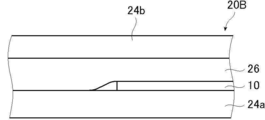
- FIG. 5 is a diagram conceptually showing an example of the windshield glass of the present invention.
- FIG. 6 is a diagram conceptually showing another example of the windshield glass of the present invention.
- FIG. 7 is a diagram conceptually showing another example of the windshield glass of the present invention.
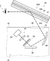
- FIG. 8 is a diagram conceptually showing an example of the HUD of the present invention.
- FIG. 9 is a conceptual diagram for explaining a method of forming an alignment film.
- visible light is light having a wavelength visible to the human eye among electromagnetic waves, and indicates light in the wavelength range of 380 to 780 nm.
- Invisible light is light in a wavelength region of less than 380 nm or in a wavelength region of more than 780 nm.
- the light in the wavelength range of 420 to 490 nm is blue light (B light)
- the light in the wavelength range of 495 to 570 nm is green light (G light).
- the light in the wavelength range of 620 to 750 nm is red light (R light).
- infrared rays indicate a wavelength range of more than 780 nm and 2000 nm or less in invisible light.
- p-polarized light means polarized light that oscillates in a direction parallel to the incident surface of light.
- the incident surface is perpendicular to the reflecting surface and means a surface containing the incident light rays and the reflected rays.
- the vibration plane of the electric field vector is parallel to the entrance plane.
- the in-plane retardation Re (in-plane phase difference) is a value measured using AxoScan manufactured by Axometrics. Unless otherwise specified, the measurement wavelength is 550 nm.
- projection image means an image based on the projection of light from a projector to be used, not the surrounding landscape such as the front.
- the projected image is observed as a virtual image that appears to emerge beyond the projected image display portion of the windshield glass when viewed from the observer.
- the “screen image” means an image displayed on a drawing device of a projector or an image drawn on an intermediate image screen or the like by the drawing device. In contrast to a virtual image, the image is a real image.
- the "visible light transmittance” is the A light source visible light transmittance defined in JIS R 3212: 2015 (safety glass test method for automobiles). That is, for the visible light transmittance, the transmittance of each wavelength in the range of 380 to 780 nm is measured with a spectrophotometer using an A light source, and the wavelength distribution of the CIE (International Lighting Commission) light adaptation standard relative luminous efficiency. And the transmittance obtained by multiplying the transmittance at each wavelength and weight averaging the weight coefficient obtained from the wavelength interval.
- CIE International Lighting Commission
- liquid crystal composition and the liquid crystal compound include those which no longer exhibit liquid crystal property due to curing or the like as a concept.
- the projected image display member of the present invention is a half mirror (half mirror film) that reflects the projected light carrying an image (projected image) and displays the image supported by the projected light as a projected image by the reflected light of the projected light. ).
- the projected image display member has visible light transmission.
- the visible light transmittance of the projected image display member is preferably 80% or more, more preferably 82% or more, still more preferably 84% or more.
- the projected image display member does not substantially show reflection in a wavelength region having high visual sensitivity.
- substantially the same reflection is shown in the vicinity of a wavelength of 550 nm. Is preferable.
- “Substantially equivalent reflection” means, for example, the reflectance of natural light (unpolarized light) at a target wavelength measured from the normal direction with a spectrophotometer such as the spectrophotometer "V-670" manufactured by JASCO Corporation.
- the difference between the two is 10% or less.
- the difference in reflectance is preferably 5% or less, more preferably 3% or less, further preferably 2% or less, and particularly preferably 1% or less.
- Visible light transmittance that meets the standards of vehicle windshield glass even when combined with glass with low visible light transmittance by showing substantially the same reflection in the wavelength range with high luminosity factor. The rate can be achieved.
- the projected image display member may be a thin film or sheet.
- the projected image display member may be in the form of a roll as a thin film before being used for the windshield glass.
- the projected image display member may have a function as a half mirror for at least a part of the projected light. Therefore, the projected image display member does not need to function as a half mirror for light in the entire visible light region, for example. Further, the projected image display member may have the function as the above-mentioned half mirror for light at all incident angles, but the above-mentioned half mirror for light at at least a part of the incident angles. It suffices to have the function as.
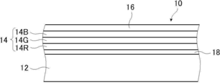
- FIG. 1 conceptually shows an example of the projected image display member of the present invention.
- the projected image display member 10 has a transparent base material 12, a selective reflection layer 14, a polarization conversion layer 16, and a sticking layer 18.
- the projected image display member 10 of the present invention is a half mirror film for reflecting projected light and displaying a projected image, and is used for a HUD in combination with, for example, windshield glass.
- the selective reflection layer 14 is arranged on the incident side of the projected light rather than the transparent base material 12. That is, in the case of the projected image display member shown in FIG. 1, the polarization conversion layer 16 is the incident surface of the projected light. Therefore, when the projected image display member 10 of the present invention is mounted on a HUD or the like, the selective reflection layer 14 is on the inside of the vehicle and the transparent base material 12 is on the outside of the vehicle.
- the projected light of the HUD is incident from the selective reflection layer 14 (polarization conversion layer 16) side and reflected.
- the outside light from the outside of the vehicle enters from the transparent base material 12, passes through the sticking layer 18, the selective reflection layer 14, and the polarization conversion layer 16 and reaches the inside of the vehicle and the like.
- the transparent base material 12 is transparent and has an in-plane retardation Re of 5000 nm or more.
- the transparent base material 12 is a characteristic member of the projected image display member of the present invention.
- the transparent base material 12 will be described in detail later.
- the sticking layer 18 is for sticking the transparent base material 12 and the selective reflection layer 14.
- the adhesive layer 18 has fluidity when bonded, and then becomes a solid. Even a layer made of an adhesive is a soft solid gel-like (rubber-like) when bonded, and is subsequently gel-like. It may be a layer made of a pressure-sensitive adhesive whose state does not change, or a layer made of a material having the characteristics of both an adhesive and a pressure-sensitive adhesive.
- the materials are acrylate type, urethane type, urethane acrylate type, and epoxy, respectively.
- Compounds such as system, epoxy acrylate system, polyolefin system, modified olefin system, polypropylene system, ethylene vinyl alcohol system, vinyl chloride system, chloroprene rubber system, cyanoacrylate system, polyamide system, polyimide system, polystyrene system, and polyvinyl butyral system.
- the photocuring type is preferable as the curing method.
- the material is preferably an acrylate-based material, a urethane acrylate-based material, an epoxy acrylate-based material, or the like.
- the sticking layer 18 may be formed by using OCA (Optical Clear Adhesive).
- OCA Optical Clear Adhesive
- a commercially available product for an image display device particularly a commercially available product for the surface of an image display unit of an image display device may be used.
- Examples of commercially available products include an adhesive sheet manufactured by Panac Co., Ltd. (PD-S1 and the like), an adhesive sheet of the MHM series manufactured by Niei Kako Co., Ltd., and the like.
- the thickness of the sticking layer 18 is preferably 0.5 to 10 ⁇ m, more preferably 1.0 to 5.0 ⁇ m. Further, the thickness of the sticking layer 18 formed by using OCA may be 10 to 50 ⁇ m, preferably 15 to 30 ⁇ m.
- the adhesive layer 18 is unnecessary.
- the selective reflection layer 14 is a layer that reflects light wavelength-selectively. Specifically, the selective reflection layer 14 is a layer that selectively reflects in a specific wavelength range. In the illustrated example, the selective reflection layer 14 selectively reflects light in a predetermined wavelength range and transmits other light.
- the selective reflection layer 14 is preferably a polarization reflection layer.
- the polarized light reflecting layer is a layer that reflects linearly polarized light, circularly polarized light, or elliptically polarized light.
- the polarized light reflecting layer is preferably a circularly polarized light reflecting layer or a linearly polarized light reflecting layer.
- the circularly polarized light reflecting layer is a layer that reflects the circularly polarized light of one of the senses (turning direction) and transmits the circularly polarized light of the other sense in the selective reflection wavelength range.
- the linearly polarized light reflecting layer is a layer that reflects linearly polarized light in one polarization direction at the center wavelength of selective reflection and transmits linearly polarized light in the polarization direction orthogonal to the reflected polarization direction.
- the polarized light reflecting layer can transmit unreflected polarized light. Therefore, by using the polarized light reflecting layer, a part of light can be transmitted even in the wavelength range where the selective reflecting layer 14 shows reflection.
- the selective reflection layer 14 is preferably a circularly polarized light reflection layer, and particularly preferably a cholesteric liquid crystal layer having a fixed cholesteric liquid crystal phase.
- the selective reflection layer 14 of the projected image display member 10 shown in the figure has a red reflection cholesteric liquid crystal layer 46R having a selective reflection center wavelength in the wavelength range of red light, and a selective reflection center wavelength in the wavelength range of green light. It has three selective reflection layers, a green reflection cholesteric liquid crystal layer 46G having a green reflection cholesteric liquid crystal layer 46G and a blue reflection cholesteric liquid crystal layer 46B having a selective reflection center wavelength in the wavelength range of blue light.
- the projected image display member 10 of the illustrated example corresponds to a full-color projected image that reflects red light, green light, and blue light, but the present invention is not limited to this.
- the selective reflective layer 14 of the projected image display member has only the red reflective cholesteric liquid crystal layer 46R and the green reflective cholesteric liquid crystal layer 46G, or has only the red reflective cholesteric liquid crystal layer 46R and the blue reflective cholesteric liquid crystal layer 46B. It may have or have only a green reflective cholesteric liquid crystal layer 46G and a blue reflective cholesteric liquid crystal layer 46B, and may correspond to a two-color projected image.
- the selective reflective layer 14 may correspond to monochrome projected light having only one of the red reflective cholesteric liquid crystal layer 46R, the green reflective cholesteric liquid crystal layer 46G, and the blue reflective cholesteric liquid crystal layer 46B. .. That is, the projection display member of the present invention basically reflects all blue light, green light, and red light when the projection light projected by the HUD projector is a full-color image. It is configured to do. When the projected light projected by the HUD projector is a two-color image, the selective reflection layer 14 is also configured to reflect two colors of the same color. When the projected light projected by the HUD projector is a monochrome image, the selective reflection layer 14 is also configured to reflect the same color.
- the cholesteric liquid crystal layer means a layer formed by fixing the cholesteric liquid crystal phase.
- the cholesteric liquid crystal layer may be a layer in which the orientation of the liquid crystal compound in the cholesteric liquid crystal phase is maintained.
- the cholesteric liquid crystal layer is typically polymerized and cured by ultraviolet irradiation, heating, etc. after the polymerizable liquid crystal compound is placed in the oriented state of the cholesteric liquid crystal phase to form a non-fluid layer, and at the same time Any layer may be used as long as it is a layer that has changed to a state in which the orientation form is not changed by an external field or an external force.
- the optical properties of the cholesteric liquid crystal phase are retained in the layer, and the liquid crystal compound in the layer does not have to exhibit liquid crystal property anymore.
- the polymerizable liquid crystal compound may lose its liquid crystal property due to its high molecular weight due to the curing reaction.
- the cholesteric liquid crystal phase selectively reflects the circular polarization of one sense of right-handed or left-handed circular polarization and exhibits circular polarization selective reflection that transmits the circular polarization of the other sense. ..
- a film containing a layer in which a cholesteric liquid crystal phase exhibiting circularly polarized selective reflectivity is fixed many films formed from a composition containing a polymerizable liquid crystal compound have been known conventionally, and the cholesteric liquid crystal layer has been conventionally known. You can refer to the technology.
- the spiral pitch P (one spiral pitch) of the spiral structure is, in other words, the length in the spiral axial direction for one spiral winding.
- the spiral pitch P is the length in the spiral axis direction in which the director of the liquid crystal compound (in the case of a rod-shaped liquid crystal, the long axis direction) that constitutes the cholesteric liquid crystal phase rotates 360 °.
- the direction of the spiral axis of the normal cholesteric liquid crystal layer coincides with the thickness direction of the cholesteric liquid crystal layer.
- SEM scanning Electron Microscope
- the spiral pitch P of the cholesteric liquid crystal layer is twice the distance between the bright lines.
- the spiral pitch P of the cholesteric liquid crystal layer is equal to the length of three bright lines and two dark lines in the thickness direction, that is, the length of three dark lines and two bright lines in the thickness direction. This length is the distance between the centers of the upper and lower bright lines or dark lines in the thickness direction.
- the selective reflection center wavelength and the full width at half maximum (full width at half maximum) of the cholesteric liquid crystal layer can be obtained as an example as follows.
- a spectrophotometer manufactured by JASCO Corporation, V-670
- a decrease peak in transmittance is observed in the selective reflection band.
- the value of the wavelength on the short wavelength side is ⁇ l (nm)
- the value of the wavelength on the long wavelength side is ⁇ h (nm)
- the selective reflection center wavelength ⁇ and the half-value width ⁇ can be expressed by the following equations.
- the selective reflection center wavelength obtained as described above substantially coincides with the wavelength at the center of gravity of the reflection peak of the circular polarization reflection spectrum measured from the normal direction of the cholesteric liquid crystal layer.
- the spiral pitch of the cholesteric liquid crystal phase depends on the type of chiral agent used together with the polymerizable liquid crystal compound and the concentration thereof added, a desired pitch can be obtained by adjusting these.
- a desired pitch can be obtained by adjusting these.
- the cholesteric liquid crystal layers are arranged in order from the one having the shortest center wavelength of selective reflection when viewed from the incident side of the projected light.
- each cholesteric liquid crystal layer a cholesteric liquid crystal layer having a spiral sense of either right or left is used.
- the sense of circularly polarized light reflected by the cholesteric liquid crystal layer matches the sense of spiraling. It is preferable that the cholesteric liquid crystal layers having a plurality of layers having different selective reflection center wavelengths have the same sense of spiral, that is, the swirling direction of the reflected circularly polarized light.
- the ⁇ n can be adjusted by adjusting the type or mixing ratio of the polymerizable liquid crystal compound, or by controlling the temperature at the time of fixing the orientation.
- a plurality of cholesteric liquid crystal layers having the same pitch P and the same spiral sense may be laminated. Circular polarization selectivity can be increased at a specific wavelength by laminating cholesteric liquid crystal layers having the same pitch P and the same spiral sense.
- the plurality of cholesteric liquid crystal layers constituting the selective reflection layer 14 may be obtained by laminating a separately prepared cholesteric liquid crystal layer using an adhesive or the like, or on the surface of the previous cholesteric liquid crystal layer formed by the method described later.
- a liquid crystal composition (coating liquid) containing a polymerizable liquid crystal compound or the like may be directly applied, and the steps of orientation and fixing may be repeated, but the latter is preferable.
- the next cholesteric liquid crystal layer directly on the surface of the previously formed cholesteric liquid crystal layer the orientation orientation of the liquid crystal molecules on the air interface side of the previously formed cholesteric liquid crystal layer and the cholesteric liquid crystal layer formed on the cholesteric liquid crystal layer. This is because the orientation directions of the lower liquid crystal molecules are the same, and the polarization characteristics of the laminated body of the cholesteric liquid crystal layer are improved. In addition, interference unevenness that may occur due to uneven thickness of the adhesive layer is not observed.
- the thickness of the cholesteric liquid crystal layer is preferably 0.2 to 10 ⁇ m, more preferably 0.5 to 10 ⁇ m, further preferably 1.0 to 8.0 ⁇ m, and particularly preferably 1.5 to 6.0 ⁇ m.
- the total thickness of the cholesteric liquid crystal layer is preferably 2.0 to 30 ⁇ m, more preferably 2.5 to 25 ⁇ m, and even more preferably 3.0 to 20 ⁇ m.
- cholesteric liquid crystal layer a material and a method for producing the cholesteric liquid crystal layer will be described.
- the material used for forming the cholesteric liquid crystal layer described above include a liquid crystal composition containing a polymerizable liquid crystal compound and a chiral agent (optically active compound). If necessary, the above-mentioned liquid crystal composition mixed with a surfactant, a polymerization initiator, etc. and dissolved in a solvent or the like is further applied to a support, an alignment film, a cholesteric liquid crystal layer as an lower layer, or the like, and cholesteric orientation. After aging, the liquid crystal composition can be fixed by curing to form a cholesteric liquid crystal layer.
- the polymerizable liquid crystal compound may be a rod-shaped liquid crystal compound or a disk-shaped liquid crystal compound, but is preferably a rod-shaped liquid crystal compound.
- Examples of the rod-shaped polymerizable liquid crystal compound forming the cholesteric liquid crystal layer include a rod-shaped nematic liquid crystal compound.
- rod-shaped nematic liquid crystal compounds examples include azomethines, azoxys, cyanobiphenyls, cyanophenyl esters, benzoic acid esters, cyclohexanecarboxylic acid phenyl esters, cyanophenylcyclohexanes, cyano-substituted phenylpyrimidines, and alkoxy-substituted phenylpyrimidines.
- Phenyldioxans, trans, and alkenylcyclohexylbenzonitriles are preferably used. Not only low molecular weight liquid crystal compounds but also high molecular weight liquid crystal compounds can be used.
- the polymerizable liquid crystal compound is obtained by introducing a polymerizable group into the liquid crystal compound.
- the polymerizable group include an unsaturated polymerizable group, an epoxy group, and an aziridinyl group, and an unsaturated polymerizable group is preferable, and an ethylenically unsaturated polymerizable group is particularly preferable.
- the polymerizable group can be introduced into the molecule of the liquid crystal compound by various methods.
- the number of polymerizable groups contained in the polymerizable liquid crystal compound is preferably 1 to 6 in one molecule, and more preferably 1 to 3.
- Examples of polymerizable liquid crystal compounds include Makromol. Chem. , 190, 2255 (1989), Advanced Materials 5, 107 (1993), US Pat. No.
- the amount of the polymerizable liquid crystal compound added to the liquid crystal composition is preferably 80 to 99.9% by mass, preferably 85 to 99.5% by mass, based on the solid content mass (mass excluding the solvent) of the liquid crystal composition. % Is more preferable, and 90 to 99% by mass is further preferable.
- the cholesteric liquid crystal layer may have a low ⁇ n.
- the low ⁇ n cholesteric liquid crystal layer can be formed by using a low ⁇ n polymerizable liquid crystal compound.
- the low ⁇ n polymerizable liquid crystal compound will be specifically described.
- a narrow-band selective reflection layer can be obtained by forming a cholesteric liquid crystal phase using a low ⁇ n polymerizable liquid crystal compound and forming a film in which the cholesteric liquid crystal phase is fixed.
- the low ⁇ n polymerizable liquid crystal compound include the compounds described in WO2015 / 115390, WO2015 / 147243, WO2016 / 035773, JP-A-2015-163596, and JP-A-2016-053149.
- the description of WO2016 / 047648 can also be referred to.
- the liquid crystal compound is also preferably a polymerizable compound represented by the following formula (I) described in WO2016 / 047648.
- A represents a phenylene group which may have a substituent or a trans-1,4-cyclohexylene group which may have a substituent
- L is a single bond, -CH 2.
- the phenylene group in the formula (I) is preferably a 1,4-phenylene group.
- the substituent when "may have a substituent" for the phenylene group and the trans-1,4-cyclohexylene group is not particularly limited, and is, for example, an alkyl group, a cycloalkyl group, an alkoxy group, or an alkyl ether. Examples thereof include a substituent selected from the group consisting of a group, an amide group, an amino group, a halogen atom, and a group composed of a combination of two or more of the above-mentioned substituents.
- the phenylene group and the trans-1,4-cyclohexylene group may have 1 to 4 substituents. When having two or more substituents, the two or more substituents may be the same or different from each other.
- the alkyl group may be either linear or branched.
- the alkyl group preferably has 1 to 30 carbon atoms, more preferably 1 to 10 carbon atoms, and even more preferably 1 to 6 carbon atoms.
- Examples of alkyl groups include methyl group, ethyl group, n-propyl group, isopropyl group, n-butyl group, isobutyl group, sec-butyl group, tert-butyl group, n-pentyl group, isopentyl group and neopentyl.
- alkyl group 1,1-dimethylpropyl group, n-hexyl group, isohexyl group, linear or branched heptyl group, octyl group, nonyl group, decyl group, undecyl group, or dodecyl group can be mentioned.
- the above description regarding the alkyl group is the same for the alkoxy group containing the alkyl group.
- specific examples of the alkylene group when referred to as an alkylene group include a divalent group obtained by removing one arbitrary hydrogen atom in each of the above-mentioned examples of an alkyl group.
- the halogen atom include a fluorine atom, a chlorine atom, a bromine atom, and an iodine atom.
- the number of carbon atoms of the cycloalkyl group is preferably 3 to 20, more preferably 5 or more, preferably 10 or less, more preferably 8 or less, still more preferably 6 or less.
- Examples of the cycloalkyl group include a cyclopropyl group, a cyclobutyl group, a cyclopentyl group, a cyclohexyl group, a cycloheptyl group, and a cyclooctyl group.
- X 3 represents a single bond, -O-, -S-, or -N (Sp 4- Q 4 )-, or a nitrogen atom forming a ring structure with Q 3 and Sp 3.
- Sp 3 and Sp 4 are independently one or more-in a single bond, a linear or branched alkylene group having 1 to 20 carbon atoms, and a linear or branched alkylene group having 1 to 20 carbon atoms.
- the replacement position is not particularly limited. Of these, a tetrahydrofuranyl group is preferable, and a 2-tetrahydrofuranyl group is particularly preferable.
- the m-1 Ls may be the same or different from each other.
- Sp 1 and Sp 2 are independently one or more-in a single bond, a linear or branched alkylene group having 1 to 20 carbon atoms, and a linear or branched alkylene group having 1 to 20 carbon atoms.
- the linking group selected from the group consisting of substituted groups is shown.
- Q 1 and Q 2 each independently represent a polymerizable group selected from the group consisting of a hydrogen atom or a group represented by the above formulas Q-1 to Q-5, where Q 1 and Q 2 have . Either one shows a polymerizable group.
- the polymerizable group an acryloyl group (formula Q-1) or a methacryloyl group (formula Q-2) is preferable.
- m represents an integer of 3 to 12.
- m is preferably an integer of 3 to 9, more preferably an integer of 3 to 7, and even more preferably an integer of 3 to 5.
- the polymerizable compound represented by the formula (I) has at least one phenylene group which may have a substituent as A and a trans-1,4-cyclohexylene group which may have a substituent. It is preferable to include at least one.
- the polymerizable compound represented by the formula (I) preferably contains 1 to 4 trans-1,4-cyclohexylene groups which may have a substituent as A, and preferably contains 1 to 3 of them. Is more preferable, and it is more preferable to contain 2 or 3 of them.
- the polymerizable compound represented by the formula (I) preferably contains 1 or more phenylene groups as A, which may have a substituent, and more preferably 1 to 4 groups. It is more preferable to include 3 pieces, and it is particularly preferable to contain 2 or 3 pieces.
- polymerizable compound represented by the formula (I) in addition to the compounds described in paragraphs 0051 to 0058 of WO2016 / 047648, Japanese Patent Application Laid-Open No. 2013-112631, Japanese Patent Application Laid-Open No. 2010-070543, Examples thereof include the compounds described in Japanese Patent No. 4725516, WO2015 / 115390, WO2015 / 147243, WO2016 / 035873, JP-A-2015-163596, and JP-A-2016-53149.
- the chiral agent has the function of inducing the helical structure of the cholesteric liquid crystal phase. Since the chiral compound has a different sense of spiral or spiral pitch depending on the compound, it may be selected according to the purpose.
- the chiral agent is not particularly limited, and known compounds can be used.
- Examples of chiral agents include Liquid Crystal Device Handbook (Chapter 3, 4-3, TN, Chiral Auxiliary for STN, page 199, Japan Society for the Promotion of Science 142, 1989), JP-A-2003-287623, Examples thereof include compounds described in JP-A-2002-302487, JP-A-2002-080478, JP-A-2002-08851, JP-A-2010-181852, and JP-A-2014-034581.
- the chiral agent generally contains an asymmetric carbon atom, but an axial asymmetric compound or a surface asymmetric compound that does not contain an asymmetric carbon atom can also be used as the chiral agent.
- Examples of axially asymmetric or surface asymmetric compounds include binaphthyl, helicene, paracyclophane, and derivatives thereof.
- the chiral agent may have a polymerizable group. When both the chiral agent and the liquid crystal compound have a polymerizable group, the repeating unit derived from the polymerizable liquid crystal compound and the repeating unit derived from the chiral agent are derived by the polymerization reaction between the polymerizable chiral agent and the polymerizable liquid crystal compound.
- the polymerizable group of the polymerizable chiral agent is preferably a group of the same type as the polymerizable group of the polymerizable liquid crystal compound. Therefore, the polymerizable group of the chiral agent is preferably an unsaturated polymerizable group, an epoxy group or an aziridinyl group, more preferably an unsaturated polymerizable group, and preferably an ethylenically unsaturated polymerizable group. Especially preferable.
- the chiral agent may be a liquid crystal compound.
- an isosorbide derivative As the chiral agent, an isosorbide derivative, an isomannide derivative, a binaphthyl derivative and the like can be preferably used.
- As the isosorbide derivative a commercially available product such as LC756 manufactured by BASF may be used.
- the content of the chiral agent in the liquid crystal composition is preferably 0.01 to 200 mol%, more preferably 1 to 30 mol% of the amount of the polymerizable liquid crystal compound.
- the content of the chiral auxiliary in the liquid crystal composition is intended to be the concentration (mass%) of the chiral agent with respect to the total solid content in the composition.
- the liquid crystal composition preferably contains a polymerization initiator.
- the polymerization initiator used is preferably a photopolymerization initiator capable of initiating the polymerization reaction by irradiation with ultraviolet rays.
- photopolymerization initiators include ⁇ -carbonyl compounds (described in US Pat. No. 2,376,661 and US Pat. No. 2,376,670), acidoin ethers (described in US Pat. No. 2,448,828), and ⁇ -hydrogens.
- Substituent aromatic acidoine compound described in US Pat. No.
- an acylphosphine oxide compound or an oxime compound is also preferable to use an acylphosphine oxide compound or an oxime compound as the polymerization initiator.
- acylphosphine oxide compound for example, a commercially available IRGACURE810 (compound name: bis (2,4,6-trimethylbenzoyl) -phenylphosphine oxide) manufactured by BASF Japan Ltd. can be used.
- Oxime compounds include IRGACURE OXE01 (manufactured by BASF), IRGACURE OXE02 (manufactured by BASF), TR-PBG-304 (manufactured by Changzhou Powerful Electronics New Materials Co., Ltd.), ADEKA ARCULS NCI-831 and ADEKA ARCULS NCI.
- a commercially available product such as -930 (manufactured by ADEKA Corporation) can be used. Only one type of polymerization initiator may be used, or two or more types may be used in combination.
- the content of the photopolymerization initiator in the liquid crystal composition is preferably 0.1 to 20% by mass, more preferably 0.5 to 5% by mass, based on the content of the polymerizable liquid crystal compound.
- the liquid crystal composition may optionally contain a cross-linking agent in order to improve the film strength and durability after curing.
- a cross-linking agent one that cures with ultraviolet rays, heat, humidity or the like can be preferably used.
- the cross-linking agent is not particularly limited and may be appropriately selected depending on the intended purpose.
- cross-linking agent examples include polyfunctional acrylate compounds such as trimethylolpropantri (meth) acrylate and pentaerythritol tri (meth) acrylate; epoxy compounds such as glycidyl (meth) acrylate and ethylene glycol diglycidyl ether; 2,2- Aziridine compounds such as bishydroxymethylbutanol-tris [3- (1-aziridinyl) propionate], 4,4-bis (ethyleneiminocarbonylamino) diphenylmethane; isocyanate compounds such as hexamethylenediisocyanate and biuret-type isocyanate; oxazoline group side Polyoxazoline compounds contained in the chain; alkoxysilane compounds such as vinyltrimethoxysilane and N- (2-aminoethyl) 3-aminopropyltrimethoxysilane can be mentioned.
- polyfunctional acrylate compounds such as trimethylolpropantri (meth) acryl
- a known catalyst can be used depending on the reactivity of the cross-linking agent, and the productivity can be improved in addition to the improvement of the film strength and durability. These may be used alone or in combination of two or more.
- the content of the cross-linking agent is preferably 3 to 20% by mass, more preferably 5 to 15% by mass. By setting the content of the cross-linking agent to 3% by mass or more, the effect of improving the cross-linking density can be obtained, and by setting the content of the cross-linking agent to 20% by mass or less, the stability of the cholesteric liquid crystal layer is lowered. Can be prevented.
- "(meth) acrylate” is used in the meaning of "any one or both of acrylate and methacrylate".
- orientation control agent An orientation control agent may be added to the liquid crystal composition, which contributes to the stable or rapid planar orientation of the cholesteric liquid crystal layer.
- the orientation control agent include the fluorine (meth) acrylate-based polymers described in paragraphs [0018] to [0043] of JP-A-2007-272185, and paragraphs [0031]-[0031] of JP-A-2012-203237. 0034] and the like, and examples thereof include compounds represented by the formulas (I) to (IV) described in JP-A-2013-113913.
- the orientation control agent one type may be used alone, or two or more types may be used in combination.
- the amount of the orientation control agent added to the liquid crystal composition is preferably 0.01 to 10% by mass, more preferably 0.01 to 5% by mass, and 0.02 to 1 to the total mass of the polymerizable liquid crystal compound. Mass% is particularly preferred.
- the liquid crystal composition may contain at least one selected from various additives such as a surfactant for adjusting the surface tension of the coating film and making the thickness uniform, and a polymerizable monomer. .. Further, if necessary, a polymerization inhibitor, an antioxidant, an ultraviolet absorber, a light stabilizer, a coloring material, metal oxide fine particles, and the like are not added to the liquid crystal composition to reduce the optical performance. It can be added in a range.
- the cholesteric liquid crystal layer is formed as follows. First, a liquid crystal composition is prepared in which a polymerizable liquid crystal compound, a polymerization initiator, and a chiral agent and a surfactant added as needed are dissolved in a solvent. Next, the prepared liquid crystal composition is applied onto the resin layer, the alignment film, the polarization conversion layer 16, the previously prepared cholesteric liquid crystal layer, or the like, and dried to obtain a coating film. Further, the coating film can be irradiated with active rays to polymerize the liquid crystal composition (polymerizable liquid crystal compound) to form a cholesteric liquid crystal layer in which the cholesteric regularity is fixed.
- the laminated film composed of a plurality of cholesteric liquid crystal layers can be formed by repeating the above-mentioned manufacturing process of the cholesteric liquid crystal layer.
- the solvent used for preparing the liquid crystal composition is not particularly limited and may be appropriately selected depending on the intended purpose, but an organic solvent is preferably used.
- the organic solvent is not particularly limited and may be appropriately selected depending on the intended purpose.
- the method for applying the liquid crystal composition to the support, the alignment film, the cholesteric liquid crystal layer as the lower layer, and the like is not particularly limited and may be appropriately selected depending on the intended purpose.
- the coating method include wire bar coating method, curtain coating method, extrusion coating method, direct gravure coating method, reverse gravure coating method, die coating method, spin coating method, dip coating method, spray coating method, and slide coating. Law etc. can be mentioned. It can also be carried out by transferring the liquid crystal composition separately coated on the support.
- the liquid crystal molecules are oriented by heating the applied liquid crystal composition.
- the heating temperature is preferably 200 ° C. or lower, more preferably 130 ° C. or lower.
- the liquid crystal composition can be cured by further polymerizing the oriented liquid crystal compound.
- the polymerization may be either thermal polymerization or photopolymerization using light irradiation, but photopolymerization is preferable. It is preferable to use ultraviolet rays for light irradiation.
- the irradiation energy is preferably 20mJ / cm 2 ⁇ 50J / cm 2, more preferably 100 ⁇ 1,500mJ / cm 2.
- light irradiation may be carried out under heating conditions or a nitrogen atmosphere.
- the irradiation ultraviolet wavelength is preferably 350 to 430 nm.
- the polymerization reaction rate is preferably high from the viewpoint of stability. Specifically, the polymerization reaction rate is preferably 70% or more, more preferably 80% or more.
- the polymerization reaction rate can be determined by measuring the consumption ratio of the polymerizable functional group by measuring the infrared absorption spectrum.
- the projected image display member 10 may use a linearly polarized light reflecting layer as the selective reflecting layer.
- the linearly polarized light reflecting layer include a polarizing plate in which thin films having different refractive index anisotropy are laminated.
- Such a polarizing plate has a high visible light transmittance similar to the cholesteric liquid crystal layer, and can reflect the projected light incident obliquely at the time of use in the HUD at a wavelength having high visual sensitivity.
- polarizing plate in which thin films having different refractive index anisotropy are laminated, for example, those described in Japanese Patent Publication No. 9-506837 can be used.
- a polarizing plate when processed under the conditions selected to obtain the refractive index relationship, a polarizing plate can be formed using a wide variety of materials.
- one of the first materials needs to have a different refractive index than the second material in the chosen direction.
- This difference in refractive index can be achieved by a variety of methods, including stretching, extrusion, or coating during or after film formation.
- it is preferable to have similar rheological properties eg, melt viscosity
- a commercially available product can be used as the polarizing plate in which thin films having different refractive index anisotropy are laminated.
- a product in which a reflective polarizing plate and a temporary support are laminated may be used.
- Examples of commercially available products include DBEF (registered trademark) (manufactured by 3M) and commercially available optical films sold as APF (Advanced Polarizing Film (manufactured by 3M)).
- the thickness of the linearly polarized light reflecting layer is preferably 2.0 to 50 ⁇ m, more preferably 8.0 to 30 ⁇ m.
- the polarization conversion layer 16 converts linearly polarized light into circularly polarized light, and also converts circularly polarized light into linearly polarized light. Alternatively, the polarization conversion layer 16 changes the polarization direction of linearly polarized light. In the projected image display member 10 of the present invention, the polarization conversion layer 16 is located on the incident side of the projected light with respect to the selective reflection layer 14.
- the polarization conversion layer 16 is not an essential component of the projected image display member of the present invention. That is, the projected image display member of the present invention may be composed of, for example, only the selective reflection layer 14 and the transparent base material 12. However, since the projected image display member has the polarization conversion layer 16, the display brightness of the projected light when used for the HUD can be improved. Therefore, it is preferable that the projected image display member of the present invention has the polarization conversion layer 16 as shown in the illustrated example.
- a retardation layer is exemplified.
- a ⁇ / 4 layer ( ⁇ / 4 retardation layer) having a phase difference in the plane direction of ⁇ / 4 is preferable.
- the in-plane retardation Re at a wavelength of 550 nm is preferably 100 to 450 nm, and more preferably 120 to 200 nm or 300 to 400 nm.
- ⁇ / 2 layer ( ⁇ / 2 retardation layer) 3 ⁇ / 4 layer (3 ⁇ / 4 retardation layer) and the like can also be used.
- the retardation layer as the polarization conversion layer 16 converts p-polarized light into circularly polarized light in the turning direction reflected by the cholesteric liquid crystal layer according to the turning direction of the circularly polarized light reflected by the cholesteric liquid crystal layer.
- the position of the slow axis is set and arranged.
- the retardation layer is not limited, and various known ones can be used as long as they can convert linearly polarized light into circularly polarized light.
- the retardation layer include a stretched polycarbonate film, a stretched norbornene-based polymer film, a transparent film oriented containing inorganic particles having compound refraction such as strontium carbonate, and an inorganic dielectric on a support.
- examples thereof include a thin film obtained by obliquely depositing a polycarbonate compound, a film in which a polymerizable liquid crystal compound is uniaxially oriented and fixed, and a film in which a liquid crystal compound is uniaxially oriented and fixed in orientation.
- a film in which a polymerizable liquid crystal compound is uniaxially oriented and fixed in orientation is preferably exemplified as a retardation layer.
- a liquid crystal composition containing a polymerizable liquid crystal compound is applied to the surface of a temporary support or an alignment film, and the polymerizable liquid crystal compound in the liquid crystal composition is nematically oriented in a liquid crystal state. After being formed into a liquid crystal, it can be fixed by curing to form a liquid crystal.
- the formation of the retardation layer in this case can be performed in the same manner as the formation of the cholesteric liquid crystal layer described above, except that the chiral agent is not added to the liquid crystal composition.
- the heating temperature is preferably 50 to 120 ° C, more preferably 60 to 100 ° C.
- the retardation layer is obtained by applying a composition containing a polymer liquid crystal compound to the surface of a temporary support or an alignment film, forming a nematic orientation in a liquid crystal state, and then cooling the orientation to fix the orientation. It may be a layer to be formed.
- the thickness of the retardation layer is not limited, but is preferably 0.2 to 300 ⁇ m, more preferably 0.5 to 150 ⁇ m, and even more preferably 1.0 to 80 ⁇ m.
- the thickness of the retardation layer formed by using the liquid crystal composition is not particularly limited, but is preferably 0.2 to 10 ⁇ m, more preferably 0.5 to 5.0 ⁇ m, and preferably 0.7 to 2.0 ⁇ m. More preferred.
- the slow phase axis Sa is set at an angle ⁇ with respect to the axis H in an arbitrary direction of the retardation layer.
- the direction of the slow-phase axis Sa can be set, for example, by rubbing the alignment film that is the lower layer of the retardation layer.
- the direction of the slow axis Sa of the retardation layer is the incident direction of the projected light for displaying the projected image and the selective reflection layer 14 when the projected image display member 10 is used for the HUD (see FIG. 8). It is preferable to determine according to the sense of the spiral of the constituent cholesteric liquid crystal layer.
- the projector emits the projected light of p-polarized light
- the projected image display member 10 reflects the p-polarized light to display the image.
- the retardation layer first converts the incident p-polarized projected light into circularly polarized light.
- the selective reflection layer 14 (cholesteric liquid crystal layer) selectively reflects this circularly polarized light and re-enters the retardation layer.
- the retardation layer converts circularly polarized light into p-polarized light.
- the projected image display member 10 reflects the incident p-polarized projected light as it is in p-polarized light.
- the retardation layer converts the incident p-polarized light into circularly polarized light in the turning direction reflected by the selective reflecting layer 14 according to the sense of circularly polarized light selectively reflected by the selective reflecting layer 14 (cholesteric liquid crystal layer).
- the direction of the slow axis Sa is set so as to do so. That is, when the selective reflection layer 14 selectively reflects the right circularly polarized light, the retardation layer is set in the direction of the slow phase axis Sa so as to make the incident p-polarized light right circularly polarized light.
- the retardation layer reverses the direction of the slow phase axis Sa so that the incident p-polarized light becomes the left circularly polarized light. Tilt to set.
- the setting of the slow phase axis of the retardation layer is regarded as the vertical direction (vertical direction) when the axis H shown in FIG. 9 is mounted on the windshield glass and used as a HUD.
- the direction of the slow axis Sa of the retardation layer may be set.
- the polarization conversion layer 16 is not limited to the retardation layer.
- the polarization conversion layer 16 is a rotating layer (twist) that swirls the polarization direction of linearly polarized light (p-polarized light), which is formed by fixing the spiral orientation structure of the liquid crystal compound twist-oriented along a spiral axis extending along the thickness direction. Layer) is also available. That is, as the polarization conversion layer 16, a optical rotation layer (optical rotation film) in which a liquid crystal compound is twisted and oriented can also be used.
- the optical rotation layer as the polarization conversion layer 16 is not limited to this, but when the number of pitches of the spiral orientation structure is x and the film thickness of the optical rotation layer is y (unit: ⁇ m), (I) 0.2 ⁇ x ⁇ 1.5 (Ii) 1.0 ⁇ y ⁇ 5.0 It is preferable to look at at least one of them.
- the optical rotation layer more preferably satisfies both the formula (i) and the formula (ii). It is preferable to satisfy.
- the spiral pitch is the same as that of the cholesteric liquid crystal layer described above.
- the pitch number x of the spiral orientation structure of the optical rotation layer By setting the pitch number x of the spiral orientation structure of the optical rotation layer to 0.2 or more, it is preferable in that the turning effect of linearly polarized light can be sufficiently obtained. By setting the pitch number x of the spiral orientation structure of the optical rotation layer to 1.5 or less, it is preferable in that linearly polarized light can be prevented from turning unnecessarily.
- the film thickness of the optical rotation layer By setting the film thickness of the optical rotation layer to 1.0 ⁇ m or more, it is preferable in that the turning effect of linearly polarized light can be sufficiently obtained. By setting the film thickness of the optical rotation layer to 5.0 ⁇ m or less, it is possible to prevent the optical rotation layer from becoming unnecessarily thick, which is preferable.
- the pitch number x of the spiral orientation structure is more preferably 0.25 to 1.3, and even more preferably 0.3 to 1.0.
- the film thickness is more preferably 1.1 to 4.5 ⁇ m, further preferably 1.2 to 4.0 ⁇ m.
- Such an optical rotation layer may be formed so as to satisfy the above-mentioned film thickness and the number of spiral pitches according to the above-mentioned cholesteric liquid crystal layer.
- the projected image display member 10 of the present invention has a transparent base material 12.
- the transparent base material 12 has an in-plane retardation Re of 5000 nm or more. Further, the transparent base material 12 has a visible light transmittance of 80% or more.
- the visible light transmittance of the transparent base material 12 is preferably 85% or more, more preferably 87% or more, still more preferably 90% or more.
- the selective reflection layer 14 is located closer to the incident side of the projected light than the transparent base material 12. Therefore, when the projected image display member 10 is mounted on the windshield glass and used as a HUD, the selective reflection layer 14 is on the inside of the vehicle (inner surface side) on the incident side of the projected light, and the transparent base material 12 is It will be on the outside (outer surface side) of the car. That is, in the projected image display member 10, the outside light first passes through the transparent base material 12 and enters the vehicle interior.
- the projected image display member 10 of the present invention has such a transparent base material 12 on the side opposite to the incident side of the projected light with respect to the selective reflection layer 14, that is, on the incident side of the external light. Improved suitability for polarized sunglasses.
- the projected light of p-polarized light is incident on the windshield glass and incorporated into the windshield glass for displaying the projected image.
- the projected image is displayed by the member 10 reflecting the p-polarized light.
- the polarization conversion layer 16 is a retardation layer
- the retardation layer converts p-polarization into circular polarization in a predetermined turning direction.
- the selective reflection layer 14 reflects this circularly polarized light, and the retardation layer reconverts it into p-polarized light to reflect the incident p-polarized light.
- the HUD of the present invention can eliminate the double image caused by the light reflected on the inner surface and the outer surface of the windshield glass by projecting the p-polarized light and reflecting the p-polarized light by the projected image display member 10. Therefore, it is not necessary to make the windshield glass wedge-shaped.
- the projected image display member 10 having the polarization conversion layer 16 can reflect the incident p-polarized light with a high reflectance without waste, the brightness of the projected image by the HUD can also be improved.
- polarized sunglasses are designed to block the s-polarized component. Therefore, in the HUD that projects the projected light of normal s-polarized light, when the driver wears polarized sunglasses, the projected image cannot be observed. On the other hand, in the HUD using the projected image display member 10 of the present invention, the projected image is p-polarized. Therefore, according to the present invention, unlike the HUD that projects s-polarized light, even when the driver uses polarized sunglasses, the projected image of the HUD can be properly observed.
- the polarized light of the non-reflective component when incident on and transmitted to a reflective layer that selectively reflects a predetermined circular polarization, such as a reflective layer using a cholesteric layer, the polarization state changes.
- the glare component that penetrates from the outside of the windshield glass is mainly s-polarized light. Therefore, the s-polarized light transmitted through the reflective layer that selectively reflects the circularly polarized light corresponding to the p-polarized light is ideally the circularly polarized light in the turning direction corresponding to the s-polarized light. This circularly polarized light is then converted into s-polarized light again by the retardation layer. Therefore, s-polarized light, which is a glare component that penetrates from the outside of the windshield glass, can be shielded by using polarized sunglasses.
- the s-polarized light incident on the windshield glass from the outside is incident on the windshield glass at various angles as well as the component incident on the reflective layer (reflection film, half mirror) of the windshield glass from the normal direction. Therefore, in the HUD in which p-polarized light is projected by the conventional retardation layer and circularly polarized light reflecting layer as shown in Patent Document 1 and Patent Document 2, the s-polarized light that has penetrated from the outside and transmitted through the reflecting layer is circular. It becomes elliptically polarized light instead of polarized light. When such elliptically polarized light passes through the retardation layer, not only s-polarized light but also p-polarized light components are mixed in the transmitted light.
- the surface of the selective reflection layer 14 opposite to the incident side of the projected light that is, in the plane of the selective reflection layer 14 on the incident side of the external light. It has a transparent base material 12 having a retardation Re of 5000 nm or more. That is, the reflected light that is incident from the outside of the windshield and whose main component is s-polarized light that becomes glare passes through the transparent base material 12 and then through the selective reflection layer 14 and the polarization conversion layer 16 to reach the inside of the vehicle. ..
- the projected image display member 10 of the present invention improves the suitability of polarized sunglasses in the HUD for projecting p-polarized light.
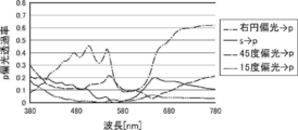
- FIG. 2 shows.
- the ratio of conversion to p-polarized light differs depending on the polarization of the incident light. Specifically, the ratio of circularly polarized light converted to p-polarized light is the highest, and the ratio of linearly polarized light having a polarization direction of 15 ° to s-polarized light is converted to p-polarized light is low. That is, in this half mirror film, the ratio of p-polarized light in the transmitted light differs depending on the polarization direction of the linearly polarized light incident from the reflection layer side.
- the transparent base material 12 having an in-plane retardation Re of 5000 nm or more
- polarization elimination occurs, and the polarized light is converted into various types of polarized light such as left and right circularly polarized light and linearly polarized light having different polarization directions.
- the ratio of polarized light converted after transmission differs depending on the angle formed by the polarization direction of the incident linearly polarized light and the slow axis of the transparent base material 12.
- the transparent base material 12 having a high in-plane retardation Re is arranged on the outside light incident side of the half mirror film having the selective reflection layer 14 and the polarization conversion layer 16, and the incident s-polarized light and the transparent base material 12
- the angle formed by the slow axis and converting the linearly polarized light incident on the selective reflection layer 14 into linearly polarized light with a low ratio of p-polarized light the s-polarized light incident as external light is converted to p-polarized light.
- the ratio to be generated can be reduced.
- the angle formed by the incident s-polarized light and the slow-phase axis of the transparent base material 12 is, to be exact, the vibration surface of the s-polarized light (the vibration direction of the s-polarized light) and the slow-phase axis of the transparent base material 12. It is the angle to be formed.
- FIG. 3 and 4 show the cholesteric liquid crystal layer side when the transparent base material is provided or not provided on the selective reflection layer side of the half mirror film having the selective reflection layer composed of the cholesteric liquid crystal layer and the ⁇ / 4 layer.
- the p-polarized light reflectance when s-polarized light is incident is shown.
- FIG. 3 shows an example in which the angle formed by the s-polarized light and the slow axis of the transparent base material is 15 °.
- FIG. 4 shows an example in which the angle formed by the polarization direction of s-polarized light and the slow axis of the transparent base material is 60 °. As shown in FIG.
- a transparent base material is placed on the selective reflection layer side of a half mirror film having a selective reflection layer composed of a cholesteric liquid crystal layer and a ⁇ / 4 layer by tilting the slow axis by 30 ° with respect to s-polarized light.
- the polarized light is polarized by the projected light of p-polarized light. It makes it possible to observe the projected image of HUD wearing sunglasses, eliminates the need to make the windshield glass wedge-shaped, and suppresses the conversion of s-polarized light incident as external light into p-polarized light. It is also possible to improve the suitability of polarized sunglasses that block the glare of external light that hinders the use of polarized sunglasses.
- the angle formed by the slow axis of the transparent base material 12 and the s-polarized light there is no limitation on the angle formed by the slow axis of the transparent base material 12 and the s-polarized light. That is, the angle formed by the slow axis of the transparent base material 12 and the s-polarized light, which can reduce the ratio of the s-polarized light incident as external light to be converted into p-polarized light, differs depending on the polarization conversion layer 16.
- the angle formed by the slow axis of the transparent base material 12 and the s-polarized light which can reduce the ratio of s-polarized light incident as external light to be converted to p-polarized light, is the case where a retardation layer is used as the polarization conversion layer 16.
- the angle formed by the slow axis of the transparent base material 12 and the s-polarized light may be appropriately set according to the polarization conversion layer 16 to be used.
- the angle formed by the slow axis of the transparent substrate 12 and the s-polarized light is preferably 10 to 30 °, more preferably 15 to 25 °.
- the s-polarized light of the external light incident on the vehicle or the like is usually linearly polarized light in the horizontal direction.
- the horizontal linearly polarized light is a linearly polarized light whose vibration surface (vibration direction) is horizontal. Therefore, in the windshield glass of the present invention, the s-polarized light is replaced with the horizontal direction to set the angle formed by the horizontal direction and the slow axis of the transparent base material 12 of the projected image display member 10. That is, in the windshield glass of the present invention, for example, when the polarization conversion layer 16 is a ⁇ / 4 layer, the angle formed by the slow axis of the transparent base material 12 and the horizontal direction is 10 to 30 °. Is preferable. The same applies to the HUD of the present invention using the windshield glass of the present invention described later.
- the material for forming the transparent base material 12 is not limited, and various materials can be used as long as the transparent base material 12 having the above-mentioned visible light transmittance and in-plane retardation Re of 5000 nm or more can be obtained.
- Acronitrile-based resin, cycloolefin-based resin and the like are exemplified.
- polyester-based resins are preferably exemplified, and among them, polyethylene terephthalate (PET) and polyethylene naphthalate (PEN) are more preferable.
- the transparent base material 12 can be produced as follows when the material is polyester such as PET. First, the polyester material is melted and extruded into a sheet. Next, the molded unstretched polyester is heated to a temperature equal to or higher than the glass transition temperature and laterally stretched by a tenter or the like. Then, the transparent base material 12 can be obtained by subjecting it to heat treatment. At this time, the in-plane retardation Re of the transparent base material 12 can be adjusted by adjusting the stretching ratio and the stretching temperature. In general, the higher the stretching ratio, the larger the in-plane retardation Re, and the lower the stretching temperature, the larger the in-plane retardation Re.
- the thickness of the transparent base material 12 there is no limitation on the thickness of the transparent base material 12. That is, the thickness of the transparent base material 12 may be appropriately set according to the stretching ratio, the stretching temperature, and the forming material so that the desired in-plane retardation Re can be obtained.
- the thickness of the transparent base material 12 is preferably 10 to 200 ⁇ m, more preferably 20 to 150 ⁇ m, and even more preferably 40 to 100 ⁇ m.
- the projected image display member 10 may have an alignment film as a lower layer to which the liquid crystal composition is applied when the selective reflection layer 14 (cholesteric liquid crystal layer) and / or the polarization conversion layer 16 is formed.
- the alignment film is a rubbing treatment of a layer made of an organic compound such as a polymer (resin such as polyimide, polyvinyl alcohol, polyester, polyarylate, polyamideimide, polyetherimide, polyamide and modified polyamide), oblique vapor deposition of an inorganic compound, and micro.
- a layer having a groove and accumulation of organic compounds for example, ⁇ -tricosanoic acid, dioctadecylmethylammonium chloride and methyl stearylate
- organic compounds for example, ⁇ -tricosanoic acid, dioctadecylmethylammonium chloride and methyl stearylate
- LB film Langmuir-Blogget method
- an alignment film whose alignment function is generated by applying an electric field, applying a magnetic field, or irradiating light may be used.
- an alignment film in which a polymer layer to be an alignment film is subjected to a rubbing treatment is preferably exemplified.
- a known method can be used for the rubbing treatment, and as an example, the rubbing treatment can be carried out by rubbing the surface of the polymer layer with paper or cloth in a certain direction.
- the liquid crystal composition may be applied to the surface of the resin layer, which will be described later, by rubbing treatment without providing the alignment film. That is, the resin layer may act as an alignment film.
- the thickness of the alignment film is not limited, but is preferably 0.01 to 5.0 ⁇ m, more preferably 0.05 to 2.0 ⁇ m.
- the alignment layer may be peeled off together with the temporary support. That is, the alignment film exists only at the time of manufacturing the projected image display member, and does not have to be a layer constituting the projected image display member when the projected image display member is completed.
- the projected image display member 10 may have a resin layer on the surface of the polarization conversion layer 16.
- the surface of the polarization conversion layer 16 is a surface opposite to the selective reflection layer 14 of the polarization conversion layer 16. Having a resin layer on the surface of the polarization conversion layer 16 is preferable in that damage to the polarization conversion layer 16 can be prevented.
- the resin layer preferably has a high visible light transmittance.
- the visible light transmittance of the resin layer is preferably 80% or more, more preferably 85% or more, still more preferably 90% or more.
- the in-plane retardation Re of the resin layer is not limited, but a smaller one is preferable.
- the in-plane retardation Re of the resin layer is preferably 10 nm or less, more preferably 5 nm or less, and even more preferably 2 nm or less.
- the thickness of the resin layer is not limited, and the thickness at which the required performance can be obtained may be appropriately set according to the purpose of forming the resin layer and the material for forming the resin layer.
- the thickness of the resin layer is preferably 5 to 1000 ⁇ m, more preferably 20 to 400 ⁇ m, still more preferably 40 to 100 ⁇ m.
- the thickness of the resin layer is preferably 5 ⁇ m or more, the effect of forming the resin layer can be preferably obtained, and a certain degree of rigidity can be secured, which is preferable in that the film can be easily positioned during transfer.
- By setting the thickness of the resin layer to 1000 ⁇ m or less it is possible to prevent the projected image display member 10 from becoming unnecessarily thick, and it is preferable in that it is easy to transfer when the reflective member has a curvature.
- the material for forming the resin layer is not limited, and various resin materials can be used as long as they satisfy the above conditions. Examples thereof include PET, TAC (triacetyl cellulose), PC (polycarbonate), COP (cycloolefin polymer), PMMA (polymethyl methacrylate) and the like.
- a glass plate may be provided on the surface of the polarization conversion layer 16 instead of the resin layer.
- Such a cast image display member 10 can be manufactured by various methods.
- a film to be an alignment film is formed on the surface of a resin film or the like to be a resin layer, and a rubbing treatment or the like is performed to form an alignment film.
- the polarization conversion layer 16 is formed on the alignment film, and the selective reflection layer 14 such as a cholesteric liquid crystal layer is formed on the surface of the polarization conversion layer 16.
- the orientation of the liquid crystal compound when the liquid crystal layers are laminated follows the orientation state of the lower liquid crystal layer.
- the laminate composed of the resin layer (alignment film), the polarization conversion layer 16 and the selective reflection layer 14 is attached to the transparent base material 12 with the selective reflection layer 14 directed by the attachment layer 18 such as OCA. , Complete the projection image display member.
- the projected image display member 10 may have a hard coat layer on the polarization conversion layer 16 or the resin layer (opposite surface of the selective reflection layer 14) to improve scratch resistance, if necessary. Good.
- the hard coat layer is preferably formed using a composition for forming a hard coat layer.
- the composition for forming a hard coat layer preferably contains a compound having three or more ethylenically unsaturated double bond groups in the molecule.
- Examples of the compound having three or more ethylenically unsaturated double bond groups in the molecule include an ester of a polyhydric alcohol and (meth) acrylic acid, vinylbenzene and its derivative, vinylsulfone, and (meth) acrylamide. Can be mentioned. Among them, from the viewpoint of hardness, a compound having three or more (meth) acryloyl groups is preferable, and an acrylate-based compound that forms a cured product having a high hardness widely used in the art can be mentioned. Examples of such a compound include an ester of a polyhydric alcohol and (meth) acrylic acid.
- ester of the polyhydric alcohol and the (meth) acrylic acid examples include pentaerythritol tetra (meth) acrylate, pentaerythritol tri (meth) acrylate, trimethylolpropane tri (meth) acrylate, and EO-modified trimethylolpropane tri (meth).
- Tris (acetyloxyethyl) isocyanurate and the like can be mentioned.
- Specific compounds of polyfunctional acrylate compounds having three or more (meth) acryloyl groups include KAYARAD DPHA, DPHA-2C, PET-30, TMPTA, TPA-320, manufactured by Nippon Kayaku Co., Ltd. TPA-330, RP-1040, T-1420, D-310, DPCA-20, DPCA-30, DPCA-60 and GPO-303, and V manufactured by Osaka Organic Chemical Industry Co., Ltd. Examples thereof include esterified compounds of polyols such as # 400 and V # 36095D and (meth) acrylic acid.
- UV-1400B UV-1700B, UV-6300B, UV-7550B, UV-7600B, UV-7605B, UV-7610B, UV-7620EA, UV-7630B, UV- 7640B, UV-6630B, UV-7000B, UV-7510B, UV-7461TE, UV-3000B, UV-3200B, UV-3210EA, UV-3310EA, UV-3310B, UV- 3500BA, UV-3520TL, UV-3700B, UV-6100B, UV-6640B, UV-2000B, UV-2010B, UV-2250EA and UV-2750B (manufactured by Nippon Synthetic Chemical Co., Ltd.) , UL-503LN (manufactured by Kyoeisha Chemical Co., Ltd.), Unidic 17-806, 17-813, V-4030 and V-4000BA (manufactured by Dainippon Ink and Chemicals Co., Ltd.), EB-1290K, EB-220 , EB-5129,
- the compound having three or more ethylenically unsaturated double bond groups in the molecule may be composed of a single compound, or a plurality of compounds may be used in combination.
- the hard coat layer can be formed by applying the above-mentioned composition for forming a hard coat layer to the surface of the resin layer, drying and curing the composition.
- the hard coat layer can be formed by the following coating method, but is not limited to this method. Dip coating method, air knife coating method, curtain coating method, roller coating method, wire bar coating method, gravure coating method, slide coating method, extrusion coating method (die coating method) (see JP-A-2003-164788), and , A known method such as a microgravure coating method is used, and among them, a microgravure coating method and a die coating method are preferable.
- ⁇ Drying and curing conditions for the hard coat layer> a preferable example of a drying and curing method in the case of forming a layer by coating such as a hard coat layer will be described below.
- it is effective to cure by combining irradiation with ionizing radiation and heat treatment before, at the same time as, or after irradiation.
- the patterns of some manufacturing processes are shown below, but are not limited thereto. In the following example, "-" indicates that the heat treatment has not been performed.
- a step of performing heat treatment at the same time as ionizing radiation curing is also preferable.
- the temperature of the heat treatment is not limited as long as it does not damage the support of the hard coat layer and the constituent layer including the hard coat layer, but is preferably 25 to 150 ° C., more preferably 30 to 80 ° C.
- the heat treatment time varies depending on the molecular weight of the component used, the interaction with other components, the viscosity, and the like, but is about 15 seconds to 1 hour, preferably 20 seconds to 30 minutes, and more preferably 30 seconds to 5 seconds. Minutes.
- the type of ionizing radiation is not particularly limited, and examples thereof include X-rays, electron beams, ultraviolet rays, visible light, and infrared rays, but ultraviolet rays are widely used.
- the coating film is ultraviolet curable, it is preferable to irradiate each layer with ultraviolet rays having an irradiation amount of 10 to 1000 mJ / cm 2 with an ultraviolet lamp to cure each layer.
- ultraviolet rays having the above-mentioned energy may be applied at once, or may be divided and irradiated.
- the ultraviolet rays in two or more times.
- initially irradiated with ultraviolet rays of 150 mJ / cm 2 or lower dose then at 50 mJ / cm 2 or more dose, and preferably against ultraviolet radiation higher than the initial dose.
- the windshield glass of the present invention is a windshield glass used for a vehicle or the like, which has the member for displaying a projected image of the present invention.
- the windshield glass of the present invention is basically a known windshield glass (windshield glass) except that it has the projected image display member of the present invention.
- the windshield glass of the present invention is generally used as a windshield for vehicles such as cars and trains, aircraft, ships, motorcycles, and vehicles such as play equipment.
- the terms “outside and inside” refer to the outside and inside of an aircraft, and the outside and inside of a ship.
- the projected light is projected onto the windshield glass from the inside of the vehicle.
- FIG. 5 conceptually shows an example of the windshield glass of the present invention using the projected image display member 10 of the present invention.
- the windshield glass 20A shown in FIG. 5 has a configuration in which the above-described projection image display member 10 of the present invention is sandwiched between the interlayer films 26, and the laminate is sandwiched between the first glass plate 24a and the second glass plate 24b.
- the projected image display member 10 may be provided on the entire surface or a part of the windshield glass 20A. In this regard, the same applies to the examples shown later.
- the first glass plate 24a is the inside of the vehicle.
- the selective reflection layer 14 and the transparent base material 12 have the selective reflection layer 14 (polarization conversion layer 16) located on the first glass plate 24a side, and the transparent base material 12 is the second glass. It is located on the plate 24b side.
- first glass plate 24a and the second glass plate 24b glass plates generally used for windshield glass can be used.
- a glass plate having a visible light transmittance of 80% or less such as 73% and 76%, such as green glass having high heat shielding property is exemplified.
- shapes of the first glass plate 24a and the second glass plate 24b various shapes can be used depending on the vehicle to be mounted and the like. Therefore, the shapes of the first glass plate 24a and the second glass plate 24b may be curved, flat, or a mixture of curved and flat surfaces.
- the thickness of the first glass plate 24a and the second glass plate 24b is not limited, and a thickness capable of obtaining sufficient strength may be appropriately set according to the material for forming the glass plate and the like.
- the thickness of the first glass plate 24a and the second glass plate 24b is preferably 0.5 to 5.0 mm, more preferably 1.0 to 3.0 mm, and even more preferably 2.0 to 2.3 mm.
- the first glass plate 24a and the second glass plate 24b may have the same material and / or different thickness.
- the interlayer film 26 is also provided on a laminated glass used as a windshield glass, which adheres the first glass plate 24a and the second glass plate 24b and prevents the glass from penetrating into the vehicle in the event of an accident.
- a known interlayer film for example, a resin film containing a resin such as polyvinyl butyral (PVB), ethylene-vinyl acetate copolymer, and chlorine-containing resin can be used.
- the above-mentioned resin is preferably the main component of the interlayer film.
- the main component means a component that occupies 50% by mass or more of the components that form an object.
- polyvinyl butyral and ethylene-vinyl acetate copolymer are preferably exemplified, and polyvinyl butyral is more preferably exemplified.
- the resin is preferably a synthetic resin.
- Polyvinyl butyral can be obtained by acetalizing polyvinyl alcohol with butyraldehyde.
- the preferred lower limit of the degree of acetalization of polyvinyl butyral described above is 40%, the preferred upper limit is 85%, the more preferred lower limit is 60%, and the more preferred upper limit is 75%.
- Polyvinyl alcohol is usually obtained by saponifying polyvinyl acetate, and polyvinyl alcohol having a saponification degree of 80 to 99.8 mol% is generally used. Further, the preferable lower limit of the degree of polymerization of the above-mentioned polyvinyl alcohol is 200, and the preferable upper limit is 3000. When the degree of polymerization of polyvinyl alcohol is 200 or more, the penetration resistance of the obtained laminated glass is unlikely to decrease, and when it is 3000 or less, the moldability of the resin film is good and the rigidity of the resin film does not become too large. Good workability. A more preferred lower limit is 500 and a more preferred upper limit is 2000.
- FIG. 6 shows another example of the windshield glass of the present invention.
- the same member is designated by the same reference numeral. Therefore, in each example, the first glass plate 24a is on the inside of the vehicle and the second glass plate 24b is on the outside of the vehicle.
- the projected image display member 10 is sandwiched between the interlayer films 26, and the laminated body is sandwiched between the first glass plate 24a and the second glass plate 24b.
- the projected image display member 10 is attached to one interlayer film 26, and the laminated body of the projected image display member 10 and one intermediate film 26 is formed.
- the structure is sandwiched between the first glass plate 24a and the second glass plate 24b.
- the selective reflection layer 14 is located on the first glass plate 24a side, and the transparent base material 12 is located on the second glass plate 24b side.
- Such a windshield glass may be produced according to a known method. For example, a laminated body in which the projected image display member 10 is sandwiched between two interlayer films 26, or a laminated body in which the projected image display member 10 is attached to one intermediate film 26 is prepared. Next, this laminated body is sandwiched between the first glass plate 24a and the second glass plate 24b. A laminated body in which two glass plates are laminated is subjected to heat treatment and pressure treatment several times, and finally heat treatment under pressure conditions using an autoclave or the like to perform a window. Make a shield glass. Examples of the pressurizing treatment include a treatment using a rubber roller.
- FIG. 7 shows another example of the windshield glass of the present invention.
- the projected image display member 10 is not arranged between the first glass plate 24a and the second glass plate 24b, but the projected image is displayed on the first glass plate 24a inside the vehicle. It has a structure in which the member 10 is attached. That is, in the windshield glass 20C shown in FIG. 7, the projected image display member 10 of the present invention is attached to the inner surface (vehicle inner surface) of the car inner glass of the known windshield glass. In the windshield glass 20C, the outside light is incident on the projected image display member 10 from the first glass plate 24a side. Further, the projected light is incident from the inside of the vehicle as in the other examples.
- the transparent base material 12 is located on the first glass plate 24a side of the selective reflection layer 14 and the transparent base material 12, and the selective reflection layer 14 is a transparent base material. It is located on the side separated from the first glass plate 24a from 12.
- the projected image display member 10 may be attached to the first glass plate 24a by a known method.
- a method of attaching the projection image display member 10 to the first glass plate 24a by using the attachment layer 18 of the projection image display member 10 described above is exemplified.
- the thickness of the sticking layer is the same as that of the sticking layer 18 described above.
- FIG. 8 conceptually shows an example of the HUD of the present invention.
- the HUD 30 shown in FIG. 8 has the windshield glass 20A of the present invention described above and the projector 32.
- the windshield glass 20B shown in FIG. 6 and the windshield glass 20C shown in FIG. 7 can also be used.
- the projector 32 projects the projected light of p-polarized light.
- the projector 32 shown in FIG. 8 includes an image forming unit 34, an intermediate image screen 36, a mirror 38, and a concave mirror 40.
- the projected light projected by the projector 32 is transmitted to the windshield glass 20A through the transmission window 46 provided on the dashboard 42 as shown by the alternate long and short dash line, and is projected and reflected by the driver.
- O Observed by O. Similar to the known HUD, in the HUD of the illustrated example, the driver O observes a virtual image of the image projected on the windshield glass 20A.
- the HUD using the projected image display member of the present invention is not limited to the HUD (Windshield HUD) that projects the projected image on the windshield glass 20A as shown in the illustrated example. That is, as the HUD that utilizes the present invention, various known HUDs that project the projected image on various members, such as a HUD (combiner HUD) that projects the projected image on a so-called combiner, can be used in various ways. At this time, the combiner has the projected image display member of the present invention.
- the image forming unit 34 has an LCD 50 (Liquid Crystal Display) and a projection lens 52. Both the LCD 50 and the projection lens 52 are known ones used in projectors for HUDs.
- the image forming unit 34 projects the image displayed by the LCD 50 onto the intermediate image screen 36 by the projection lens 52.
- an intermediate image screen 36 creates a real image, and the real image is reflected by a mirror 38 and a concave mirror 40 in a predetermined optical path. As described above, this reflected light is transmitted through the transmission window 46 provided on the dashboard 42, projected onto the windshield glass 20A, and observed by the driver O (see the alternate long and short dash line).
- the LCD 50 displays a p-polarized image (projected image).
- a polarizing plate that converts the projected light from the LCD 50 into p-polarized light is provided in the middle of the optical path of the projected light from the LCD 50 to the concave mirror 40.
- a polarizing plate that converts the projected light from the LCD 50 into p-polarized light may be provided outside the projector 32, that is, in the middle of the optical path of the projected light from the concave mirror 40 to the windshield glass 20A. In this case, this polarizing plate is also regarded as an optical element constituting the projector 32.
- a polarizing plate in which thin films having different refractive index anisotropy are laminated can be mentioned.
- the polarizing plate in which thin films having different refractive index anisotropy are laminated for example, those described in Japanese Patent Publication No. 9-506837 can be used.
- a polarizing plate when processed under the conditions selected to obtain the refractive index relationship, a polarizing plate can be formed using a wide variety of materials. In general, one of the first materials needs to have a different refractive index than the second material in the chosen direction. This difference in refractive index can be achieved by a variety of methods, including stretching, extrusion, or coating during or after film formation.
- a commercially available product may be used as the polarizing plate in which thin films having different refractive index anisotropy are laminated.
- a product in which a reflective polarizing plate and a temporary support are laminated may be used.
- Examples of commercially available products include DBEF (manufactured by 3M) and APF (Advanced Polarizing Film (manufactured by 3M)).
- DBEF manufactured by 3M
- APF Advanced Polarizing Film
- the polarizing plate an absorption type polarizing plate containing an iodine compound and a general linear polarizing plate such as a reflection type polarizing plate such as a wire grid can also be used.
- the image forming unit 34 is not limited to the one using the LCD 50, and various known image forming means used in the HUD projector can be used.
- HUD projectors such as a fluorescent display tube, LCOS (Liquid Crystal on Silicon) using liquid crystal, organic electroluminescence (organic EL) display, and DLP (Digital Light Processing) using DMD (Digital Micromirror Device), etc.
- LCOS Liquid Crystal on Silicon
- organic EL organic electroluminescence
- DLP Digital Light Processing
- the projected image is projected on the intermediate image screen 36 by the projection lens as in the LCD 50.
- an image forming means of the image forming unit 34 a light beam modulated according to the formed image is irradiated from a light source, R light, G light and B light are combined as necessary, and then the light beam is used. It is also possible to use an image forming means by optical beam scanning (optical beam scanning), which forms a projected image by converting The light beam may be modulated according to the projected image by directly modulating the light source or by using an external light modulator.
- the light source include an LED (Light Emitting Diode, a light emitting diode, an organic light emitting diode (including an OLED (Organic Light Emitting Diode)), a discharge tube, and a laser light source.
- Examples of the two-dimensional optical deflector include a galvanometer mirror (galvanometer mirror), a combination of a galvanometer mirror and a polygon mirror, and a MEMS (Micro Electro Mechanical Systems). Among them, MEMS is preferably used.
- the scanning method is not limited, and known light beam scanning methods such as random scan and raster scan can be used. Among them, raster scan is preferably exemplified.
- the projected light emitted from the image forming unit 34 is then made into a real image (visible image) by the intermediate image screen 36.
- the intermediate image screen 36 is not limited, and various known intermediate image screens that realize a projected image in a HUD projector can be used.
- Examples of the intermediate image screen 36 include a scattering film, a microlens array, and a screen for rear projection.
- the intermediate image screen 36 has birefringence, such as when a plastic material is used as the intermediate image screen 36, the polarizing plane and the light intensity of the polarized light incident on the intermediate image screen 36 are disturbed, and as a result, the projected image has color unevenness. Etc. are likely to occur. In this case, the problem of color unevenness can be reduced by using a retardation layer having a predetermined retardation.
- the intermediate image screen 36 preferably has a function of spreading and transmitting the incident projected light. This is because the projected image can be enlarged and displayed.
- an intermediate image screen composed of a microlens array is exemplified.
- the microarray lens used in the HUD is described in, for example, Japanese Patent Application Laid-Open No. 2012-226303, Japanese Patent Application Laid-Open No. 2010-145745, and Japanese Patent Application Laid-Open No. 2007-523369.
- the projected light realized by the intermediate image screen 36 is reflected by the mirror 38 and the concave mirror 40 in a predetermined optical path, transmitted through the transmission window 46 provided in the dashboard 42, and is a windshield. It is projected on glass 20A and observed by driver O (see single-point chain line).
- the mirror 38 is a known mirror used for adjusting the optical path of projected light in a projector. Further, the mirror 38 may be a so-called cold mirror that reflects visible light and transmits infrared rays to prevent heating of the constituent members of the projector by sunlight incident from the windshield glass.
- the concave mirror 40 is a known concave mirror (concave mirror) used in a HUD projector that magnifies and projects the projected light.
- the projector 32 in the illustrated example uses the mirror 38 and the concave mirror 40 as members for changing the optical path of the projected light, but the present invention is not limited thereto.
- the projector 32 may have only one of the mirror 38 and the concave mirror 40, or in addition to or in addition to the mirror 38 and / or the concave mirror 40, another light reflecting element such as a free-form curved mirror may be used.
- You may have one or more. That is, as long as the projector constituting the HUD of the present invention can project the projected light of p-polarized light, a configuration using various light reflecting elements can be used.
- the p-polarized light projected by the projector 32, transmitted through the transmission window 46, and incident on the windshield glass 20A is transmitted through the first glass plate 24a and the interlayer film 26, and is incident on the projected image display member 10. .
- the polarization conversion layer 16 is a ⁇ / 4 plate
- the projected light of p-polarized light incident on the projected image display member 10 is converted into circular polarization in the turning direction corresponding to p-polarization by the polarization conversion layer 16. Will be done.
- the converted circularly polarized light is reflected by the selective reflection layer 14.
- the circularly polarized light projected by the selective reflection layer 14 is converted into p-polarized light again by the polarization conversion layer 16 ( ⁇ / 4 plate) and emitted as reflected light, and is observed by the driver O as a projected image.
- This projected light is p-polarized. Therefore, even when the driver O wears polarized sunglasses that block s-polarized light, the projected image can be suitably observed.
- the external light incident on the outer surface of the windshield glass 20A passes through the second glass plate 24b and the interlayer film 26 and is incident on the projected image display member 10 from the transparent base material 12 side.
- the glaring s-polarized light incident on the projected image display member 10 first passes through the transparent base material 12 and is converted into p-polarized light by the selective reflection layer 14 and the polarization conversion layer 16 ( ⁇ / 4 plate). It is converted to light with few components. This light then passes through the selective reflection layer 14 and the polarization conversion layer 16 and penetrates into the vehicle through the interlayer film 24 and the first glass plate 24a. Therefore, of the outside light that has entered the vehicle, the glare component is mainly s-polarized light, which is shielded by polarized sunglasses and does not interfere with driving.
- the present invention is not limited to the above-described embodiment and does not deviate from the gist of the present invention. Of course, various improvements and changes may be made in.
- Composition 1 for forming a cholesteric liquid crystal layer forming a cholesteric liquid crystal layer having a selective reflection center wavelength of 480 nm at an incident angle of 5 ° by mixing the following components, cholesteric having a selective reflection center wavelength of 650 nm at an incident angle of 5 °
- a cholesteric liquid crystal layer forming composition 2 for forming a liquid crystal layer and a cholesteric liquid crystal layer forming composition 3 for forming a cholesteric liquid crystal layer having an incident angle of 5 ° and a selective reflection center wavelength of 700 nm were prepared.
- compositions 1, 2 and 3 for forming a cholesteric liquid crystal layer ⁇ ⁇ Mixture 1 100 parts by mass ⁇ Orientation control agent 1 (fluorine-based horizontal alignment agent 1) 0.05 parts by mass ⁇ Orientation control agent 2 (fluorine-based horizontal alignment agent 2) 0.02 parts by mass ⁇
- Right-turning chiral agent LC756 Adjusted and polymerized initiator according to the target reflection wavelength (IRGACURE OXE01, manufactured by BASF) 1.0 part by mass ⁇ Solvent (methyl ethyl ketone) Amount that makes the solute concentration 20% by mass ⁇ -
- compositions 1 to 3 for forming a cholesteric liquid crystal layer were prepared into compositions 1 to 3 for forming a cholesteric liquid crystal layer by adjusting the prescription amount of the right-turning chiral agent LC756.
- a single-layer cholesteric liquid crystal layer was prepared on the support in the same manner as in the production of the selective reflection layer described later, and the reflection characteristics of visible light were confirmed.
- the film thickness was 0.2 ⁇ m for the cholesteric liquid crystal layer forming composition 1, 0.7 ⁇ m for the cholesteric liquid crystal layer forming composition 2, and 2 ⁇ m for the cholesteric liquid crystal layer forming composition 3.
- all of the produced cholesteric liquid crystal layers are right-handed circularly polarized light reflecting layers, and the selective reflection center wavelength at an incident angle of 5 ° is 480 nm for the cholesteric liquid crystal layer forming composition 1 and 480 nm for the cholesteric liquid crystal layer forming composition 2.
- the wavelength was 650 nm
- the composition 3 for forming a cholesteric liquid crystal layer was 700 nm.
- composition for forming a retardation layer The following components were mixed to prepare a composition for forming a retardation layer having the following composition.
- ⁇ Composition for forming a retardation layer ⁇ ⁇ Mixture 1 100 parts by mass ⁇ Orientation control agent 1 0.05 parts by mass ⁇ Orientation control agent 2 0.01 parts by mass ⁇ Polymerization initiator IRGACURE OXE01 (manufactured by BASF) 1.0 part by mass ⁇ Solvent (methyl ethyl ketone) Amount that makes the solute concentration 20% by mass ⁇ -
- Example 1 ⁇ Manufacture of projecting image display member >> ⁇ Saponification of cellulose acylate film>
- a 40 ⁇ m cellulose acylate film (TAC film) obtained by the same production method as in Example 20 of International Publication No. 2014/112575 is passed through a dielectric heating roll having a temperature of 60 ° C. to bring the film surface temperature to 40 ° C.
- an alkaline solution having the composition shown below was applied to one side of the film using a bar coater at a coating amount of 14 mL / m 2 , and heated to 110 ° C. a steam-type far-infrared heater (manufactured by Noritake Company Limited). ) For 10 seconds.
- the cellulose acylate film 1 was saponified by allowing it to stay in a drying zone at 70 ° C. for 5 seconds and drying.
- the in-plane retardation Re of the cellulose acylate film 1 was measured by AxoScan and found to be 1 nm.
- composition of composition for forming an alignment film ⁇ ⁇ 28 parts by mass of modified polyvinyl alcohol ⁇ Citric acid ester (AS3, manufactured by Sankyo Chemical Co., Ltd.) 1.2 parts by mass ⁇ Photoinitiator (Irgacure 2959, manufactured by BASF) 0.84 parts by mass ⁇ Glutaraldehyde 2.8 parts by mass ⁇ 699 parts by mass of water and 226 parts by mass of methanol ⁇
- ⁇ Formation of retardation layer> As conceptually shown in FIG. 9, on the surface of the alignment film of the cellulose acylate film 1 on which the alignment film is formed, 90 ° clockwise with respect to the longitudinal direction of the cellulose acylate film 1 when viewed from the alignment film surface. A rubbing treatment (rayon cloth, pressure: 0.1 kgf (0.98N), rotation speed: 1000 rpm (revolutions per minute), transport speed: 10 m / min, number of times: 1 reciprocation) was performed in the direction of rotation.
- H is the longitudinal direction of the cellulose acylate film 1
- Sa is the direction of the rubbing treatment
- the angle ⁇ is 45 °.
- the composition for forming a retardation layer was applied to the rubbed surface of the alignment film on the cellulose acylate film 1 using a wire bar. After that, the coating film is dried and placed on a hot plate at 50 ° C., and in an environment with an oxygen concentration of 1000 ppm or less, an electrodeless lamp "D valve" (60 mW / cm 2 ) manufactured by Fusion UV Systems Co., Ltd. is used for 6 seconds.
- the liquid crystal phase was fixed by irradiating with ultraviolet rays to obtain a ⁇ / 4 layer as a polarization conversion layer.
- the film thickness of the produced ⁇ / 4 layer was measured by a non-contact film thickness meter (F20 manufactured by Filmometrics Co., Ltd.), it was 0.7 ⁇ m.
- the retardation of the produced retardation layer was measured using AxoScan and found to be 140 nm.
- a coating layer was obtained by applying the cholesteric liquid crystal layer forming composition 1 to the surface of the formed retardation layer at room temperature using a wire bar so that the thickness of the dry film after drying was 0.2 ⁇ m. ..
- the coating layer is dried at room temperature for 30 seconds, then heated in an atmosphere of 85 ° C. for 2 minutes, and then at 60 ° C. in an environment with an oxygen concentration of 1000 ppm or less, which is a D valve (90 mW / cm 2) manufactured by Fusion UV Systems.
- the cholesteric liquid crystal phase was fixed by irradiating ultraviolet rays at an output of 60% for 6 to 12 seconds with a lamp) to obtain a cholesteric liquid crystal layer having a thickness of 0.2 ⁇ m.
- the same process was repeated using the cholesteric liquid crystal layer forming composition 2 on the surface of the obtained cholesteric liquid crystal layer to obtain a cholesteric liquid crystal layer having a thickness of 0.7 ⁇ m.
- the same process was repeated using the cholesteric liquid crystal layer forming composition 3 on the surface of the obtained cholesteric liquid crystal layer to obtain a cholesteric liquid crystal layer having a thickness of 2 ⁇ m.
- a laminate A having a cellulose acylate film 1 having an alignment film, a retardation layer, and a selective reflection layer composed of three cholesteric liquid crystal layers was obtained.
- the reflection spectrum of the laminate A was measured with a spectrophotometer (V-670, manufactured by JASCO Corporation). As a result, a reflection spectrum having a selective reflection center wavelength at a wavelength of 480 nm, a wavelength of 650 nm, and a wavelength of 700 nm was obtained at an incident angle of 5 °.
- the PET material was melted at 290 ° C., extruded into a sheet through a film forming die, and cooled by being brought into close contact with a water-cooled rotary quenching drum to prepare an unstretched film.
- This unstretched film was preheated at 120 ° C. for 1 minute by a biaxial stretching test device (manufactured by Toyo Seishin Co., Ltd.), and then stretched at 120 ° C. at a stretching ratio of 4.5 times. Then, it was stretched to a stretching ratio of 1.5 times in a direction orthogonal to the previous stretching direction.
- a transparent substrate having a refractive index in the slow axis direction of 1.70, a refractive index in the phase advance axis direction of 1.60, a film thickness of 84 ⁇ m, and an in-plane retardation Re at a wavelength of 550 nm was produced. These measurements were performed using AxoScan.
- the produced laminate A was attached to a transparent substrate by OCA (MHM-UVC15, manufactured by Niei Kako Co., Ltd.). The sticking was performed by directing the cholesteric liquid crystal layer (selective reflective layer) toward the transparent substrate. Further, in the attachment, the H direction in the alignment film forming the ⁇ / 4 layer is regarded as the vertical direction, and the angle of the slow axis of the transparent base material with respect to the direction orthogonal to the H direction (horizontal direction) is 15 °. As described above, the transparent base material was attached.
- the short side of the obtained projected image display member was cut into a size of 250 mm on the short side (vertical) and 280 mm on the long side (horizontal) so as to coincide with the vertical direction (H direction).
- a glass plate manufactured by Central Glass Co., Ltd., FL2, visible light transmittance 90% having a length of 300 mm, a width of 300 mm, and a thickness of 2 mm was prepared.
- a PVB film was placed as an interlayer film having a thickness of 0.38 mm manufactured by Sekisui Chemical Co., Ltd., which was cut to the same size.
- a sheet-shaped projection image display member was installed on the interlayer film with the retardation layer side facing up. The projected image display member and the glass plate were installed so as to be vertically and horizontally aligned.
- a glass plate (manufactured by Central Glass Co., Ltd., FL2, visible light transmittance 90%) having a length of 300 mm, a width of 300 mm, and a thickness of 2 mm was installed on the projected image display member.
- This laminate was held at 90 ° C. and 10 kPa (0.1 atm) for 1 hour, and then heated in an autoclave (manufactured by Kurihara Seisakusho) at 115 ° C. and 1.3 MPa (13 atm) for 20 minutes to remove air bubbles. , Obtained a laminated glass.
- Example 2 A member for displaying a projected image was produced in the same manner as in Example 1 except that it did not have a ⁇ / 4 layer as a polarization conversion layer.
- the layer structure of the produced video display member is as follows. Transparent substrate / OCA / 3-layer cholesteric liquid crystal layer / TAC Using this projected image display member, laminated glass was produced in the same manner as in Example 1.
- the transparent base material is not provided with the ⁇ / 4 layer as the polarization conversion layer as in Example 2
- the transparent base material is subjected to an orientation treatment such as rubbing, and a cholesteric liquid crystal layer is formed on the alignment treatment surface of the transparent base material. It is also possible to form.
- Example 3 Composition for forming optical rotation layer
- the following components were mixed to prepare a composition for forming an optical rotation layer having the following composition.
- ⁇ Composition for forming an optical rotation layer ⁇ ⁇ Mixture 1 100 parts by mass ⁇ Orientation control agent 1 0.05 parts by mass ⁇ Orientation control agent 2 0.02 parts by mass ⁇
- Right swivel chiral agent LC756 (manufactured by BASF) 0.47 parts by mass ⁇
- Polymerization initiator IRGACURE OXE01 (Made by BASF) 1.0 part by mass ⁇ Solvent (methyl ethyl ketone) Amount that makes the solute concentration 20% by mass ⁇ -
- the film thickness d of the spiral structure can be expressed by "pitch P of the spiral structure x number of pitches".
- the pitch P of the spiral structure is the length of one pitch in the spiral structure.
- a composition for forming a polarization conversion layer was prepared so that the selective reflection center wavelength ⁇ was 5550 nm in the case of a cholesteric liquid crystal layer, and the film thickness of the coating film was such that the number of pitches was 0.7. The thickness was 2.5 ⁇ m.
- the layer structure of the produced video display member is as follows. Transparent base material / OCA / 3-layer cholesteric liquid crystal layer / optical rotation layer / TAC Using this projected image display member, laminated glass was produced in the same manner as in Example 1.
- Example 4 The same cast image display member as in Example 1 was produced.
- the layer structure is as follows. Transparent base material / OCA / 3-layer cholesteric liquid crystal layer / ⁇ / 4-layer / TAC
- a glass plate (manufactured by Central Glass Co., Ltd., FL2, visible light transmittance 90%) having a length of 300 mm, a width of 300 mm, and a thickness of 2 mm was prepared.
- a PVB film was placed as an interlayer film having a thickness of 0.38 mm manufactured by Sekisui Chemical Co., Ltd., which was cut to the same size.
- a glass plate (manufactured by Central Glass Co., Ltd., FL2, visible light transmittance 90%) having a length of 300 mm, a width of 300 mm, and a thickness of 2 mm was placed on the interlayer film. This laminate was held at 90 ° C.
- a member for displaying a projected image was attached to one surface of the produced laminated glass by OCA (MHM-UVC15 manufactured by Niei Kako Co., Ltd.).
- the projected image display member and the glass plate were attached vertically and horizontally in the same manner.
- Example 5 The same cast image display member as in Example 2 was produced.
- the layer structure is as follows. Transparent substrate / OCA / 3-layer cholesteric liquid crystal layer / TAC This projected image display member was attached to the same laminated glass as in Example 4 in the same manner as in Example 4.
- Example 6 In the preparation of the transparent base material, the transparent base material was prepared in the same manner as in Example 1 except that the film thickness was set to 60 ⁇ m. The in-plane retardation Re of the transparent substrate prepared in the same manner as in Example 1 was measured and found to be 6000 nm. A member for displaying a projected image was produced in the same manner as in Example 1 except that this transparent base material was used.
- the layer structure is as follows. Transparent base material / OCA / 3-layer cholesteric liquid crystal layer / ⁇ / 4-layer / TAC This projected image display member was attached to the same laminated glass as in Example 4 in the same manner as in Example 4.
- Example 7 In the preparation of the transparent base material, the transparent base material was prepared in the same manner as in Example 1 except that the film thickness was 100 ⁇ m. The in-plane retardation Re of the transparent substrate prepared in the same manner as in Example 1 was measured and found to be 10000 nm. A member for displaying a projected image was produced in the same manner as in Example 1 except that this transparent base material was used.
- the layer structure of the produced video display member is as follows. Transparent base material / OCA / 3-layer cholesteric liquid crystal layer / ⁇ / 4 layer / TAC This projected image display member was attached to the same laminated glass as in Example 4 in the same manner as in Example 4.
- Example 8 When the laminate A and the transparent base material are attached, the angle of the slow axis of the transparent base material with respect to the direction (horizontal direction) orthogonal to the H direction (vertical direction) in the alignment film forming the ⁇ / 4 layer is A member for displaying a projected image was produced in the same manner as in Example 1 except that the transparent base material was attached so as to be 40 °.
- the layer structure of the produced video display member is as follows. Transparent base material / OCA / 3-layer cholesteric liquid crystal layer / ⁇ / 4 layer / TAC A laminated glass was produced in the same manner as in Example 1 except that the projected image display member was used.
- Example 1 A projected image display member was produced in the same manner as in Example 1 except that a TAC film having a thickness of 40 ⁇ m and an in-plane retardation Re of 1 nm was used instead of the transparent base material.
- the layer structure of the produced video display member is as follows. TAC / OCA / 3-layer cholesteric liquid crystal layer / ⁇ / 4-layer / TAC
- a laminated glass was produced in the same manner as in Example 1 except that the projected image display member was used.
- the transparent base material was prepared in the same manner as in Example 1 except that the film thickness was 32 ⁇ m.
- the in-plane retardation Re was measured in the same manner as in Example 1, it was 3200 nm.
- a member for displaying a projected image was produced in the same manner as in Example 1 except that this transparent base material (PET) was used.
- PET transparent base material
- the layer structure of the produced video display member is as follows. PET / OCA / 3-layer cholesteric liquid crystal layer / ⁇ / 4-layer / TAC
- a laminated glass was produced in the same manner as in Example 1 except that the projected image display member was used.
- Example 3 A member for displaying a projected image was produced in the same manner as in Example 1 except that the transparent base material was not attached.
- the layer structure of the produced video display member is as follows. 3-layer cholesteric liquid crystal layer / ⁇ / 4 layer / TAC A laminated glass was produced in the same manner as in Example 1 except that the projected image display member was used.
- Example 4 Using the same transparent substrate (Re 8400 nm PET) as in Example 1 instead of the cellulose acylate film, the alignment film, ⁇ / 4 layer and selective reflection layer (3-layer cholesteric liquid crystal layer) are used as in Example 1. Was formed to produce a member for displaying a projected image. The relationship between the slow axis of the transparent substrate and the H direction of the alignment film was the same as in Example 1. The layer structure of the produced video display member is as follows. 3-layer cholesteric liquid crystal layer / ⁇ / 4 layer / transparent base material Using this projected image display member, laminated glass was produced in the same manner as in Example 1.
- the prepared laminated glass was evaluated as follows. [Evaluation of brightness] From the glass surface on the polarization conversion layer ( ⁇ / 4 layer, optical rotation layer) side, p-polarized light is incident from the direction of 65 ° with respect to the normal direction of the laminated glass, and the reflectance spectrum of the specularly reflected light is measured by a specular photometer (spectrum It was measured by V-670) manufactured by JASCO Corporation. The specularly reflected light is the reflected light in the incident surface on the side opposite to the incident direction with respect to the normal direction and at 65 ° with respect to the normal direction. At this time, a linear polarizing plate was placed on the light receiving portion of the spectrophotometer.
- the linear polarizing plate made the direction of the transmission axis parallel to the direction of the p-polarized light incident on the spectrophotometer. That is, this linear polarizing plate acts as polarized sunglasses. Further, the vertical direction (vertical direction) of the laminated glass and the direction of p-polarized light incident on the laminated glass were made parallel. Therefore, the transmission axis of the ⁇ / 4 layer is 45 ° with respect to s-polarized light and p-polarized light.
- the reflectance is multiplied by a coefficient according to the visual sensitivity and the emission spectrum of a general liquid crystal display device to calculate the projected image reflectance, which is used as the brightness. evaluated.
- the brightness was evaluated according to the following evaluation criteria.
- a Evaluation is a level at which the projected image can be clearly observed even in fine weather.
- the B rating the projected image can be observed, but it is a little difficult to see in fine weather.
- the C rating is a level at which it is difficult to see the projected image.
- the transmission axis of the ⁇ / 4 layer is 45 ° with respect to s-polarized light and p-polarized light.
- the visible light transmittance was calculated by multiplying the coefficient corresponding to the luminosity factor and the emission spectrum of the D65 light source at wavelengths of every 10 nm from 380 to 780 nm, and evaluated as the suitability for polarized sunglasses.
- the suitability of polarized sunglasses was evaluated according to the following evaluation criteria. Evaluation Criteria for Polarized Sunglasses Suitability A Less than 3% B 3% or more and less than 5% C 5% or more The results are shown in the table below.
- the projected image display member of the present invention having a transparent substrate on the incident side of the external light, p-polarized light incident from the transparent substrate side and transmitted through the projected image display member.
- the components can be reduced, and high suitability for polarized sunglasses can be obtained in HUD and the like.
- the projected image display member has a ⁇ / 4 layer as the polarization conversion layer, the slow axis of the transparent base material and the s-polarized light (horizontal). By setting the angle formed by the direction) to 30 ° or less, better suitability for polarized sunglasses can be obtained.
- the projected image display member has a polarization conversion layer, so that the p-polarized luminance, that is, the HUD display luminance can be improved. ..
- Comparative Example 1 using a TAC film having an in-plane retardation Re of 1 nm instead of a transparent substrate Comparative Example 2 using a PET substrate but having an in-plane retardation Re of 3200 nm, and external light incident.
- Comparative Example 3 which does not have a base material on the side the suitability for polarized sunglasses is low, and when HUD is used, the glare that hinders driving cannot be shielded by the polarized sunglasses.
- Comparative Example 4 in which the transparent base material is located on the incident side of the projected light the p-polarized luminance, that is, the display luminance of the HUD is low. From the above results, the effect of the present invention is clear.
- Projection image display member 12 Transparent base material 14 Selective reflective layer 14R Red reflective cholesteric liquid crystal layer 14G Green reflective cholesteric liquid crystal layer 14B Blue reflective cholesteric liquid crystal layer 16 Polarization conversion layer 18
- Adhesive layer 20A, 20B, 20C Windshield glass 24a No. 1 glass plate 24b 2nd glass plate 26 interlayer film 30 HUD 32 Projector 34 Image forming part 36 Intermediate image screen 38 Mirror 40 Concave mirror 42 Dashboard 46 Transparent window 50 LCD (Liquid crystal display) 52 Projection lens O Driver
Landscapes
- Physics & Mathematics (AREA)
- General Physics & Mathematics (AREA)
- Optics & Photonics (AREA)
- Nonlinear Science (AREA)
- Crystallography & Structural Chemistry (AREA)
- Chemical & Material Sciences (AREA)
- Engineering & Computer Science (AREA)
- Mathematical Physics (AREA)
- Spectroscopy & Molecular Physics (AREA)
- Multimedia (AREA)
- Mechanical Engineering (AREA)
- Overhead Projectors And Projection Screens (AREA)
- Polarising Elements (AREA)
- Instrument Panels (AREA)
- Laminated Bodies (AREA)
Priority Applications (2)
| Application Number | Priority Date | Filing Date | Title |
|---|---|---|---|
| JP2021549002A JP7314294B2 (ja) | 2019-09-27 | 2020-09-24 | 投映像表示用部材、ウインドシールドガラスおよびヘッドアップディスプレイシステム |
| US17/700,666 US20220214544A1 (en) | 2019-09-27 | 2022-03-22 | Projection image displaying member, windshield glass, and head-up display system |
Applications Claiming Priority (2)
| Application Number | Priority Date | Filing Date | Title |
|---|---|---|---|
| JP2019-177963 | 2019-09-27 | ||
| JP2019177963 | 2019-09-27 |
Related Child Applications (1)
| Application Number | Title | Priority Date | Filing Date |
|---|---|---|---|
| US17/700,666 Continuation US20220214544A1 (en) | 2019-09-27 | 2022-03-22 | Projection image displaying member, windshield glass, and head-up display system |
Publications (1)
| Publication Number | Publication Date |
|---|---|
| WO2021060407A1 true WO2021060407A1 (ja) | 2021-04-01 |
Family
ID=75166229
Family Applications (1)
| Application Number | Title | Priority Date | Filing Date |
|---|---|---|---|
| PCT/JP2020/036123 Ceased WO2021060407A1 (ja) | 2019-09-27 | 2020-09-24 | 投映像表示用部材、ウインドシールドガラスおよびヘッドアップディスプレイシステム |
Country Status (3)
| Country | Link |
|---|---|
| US (1) | US20220214544A1 (https=) |
| JP (1) | JP7314294B2 (https=) |
| WO (1) | WO2021060407A1 (https=) |
Families Citing this family (3)
| Publication number | Priority date | Publication date | Assignee | Title |
|---|---|---|---|---|
| JP7454649B2 (ja) * | 2020-03-30 | 2024-03-22 | 富士フイルム株式会社 | 反射フィルム、ウインドシールドガラスおよびヘッドアップディスプレイシステム |
| CN120266038A (zh) * | 2022-11-23 | 2025-07-04 | Lg电子株式会社 | 避开太阳光的车辆用影像装置 |
| WO2025173666A1 (ja) * | 2024-02-14 | 2025-08-21 | 富士フイルム株式会社 | コンバイナー、ヘッドアップディスプレイシステム |
Citations (4)
| Publication number | Priority date | Publication date | Assignee | Title |
|---|---|---|---|---|
| US5486840A (en) * | 1994-03-21 | 1996-01-23 | Delco Electronics Corporation | Head up display with incident light filter |
| JP2017187685A (ja) * | 2016-04-07 | 2017-10-12 | 日本化薬株式会社 | 曲面形状の光反射フィルム及びその製造方法、ならびに当該光反射フィルムを用いた光制御フィルム、光学フィルム、機能性ガラスおよびヘッドアップディスプレイ |
| WO2018012469A1 (ja) * | 2016-07-15 | 2018-01-18 | 富士フイルム株式会社 | 波長選択性反射膜、光学フィルム、波長選択性反射膜の製造方法および画像表示装置 |
| JP2019028373A (ja) * | 2017-08-02 | 2019-02-21 | スリーエム イノベイティブ プロパティズ カンパニー | 表示装置、及び赤外光カットフィルム |
Family Cites Families (12)
| Publication number | Priority date | Publication date | Assignee | Title |
|---|---|---|---|---|
| JP5669034B2 (ja) | 2009-02-26 | 2015-02-12 | 大日本印刷株式会社 | 電磁波反射部材 |
| DE102013206505B4 (de) | 2013-04-12 | 2020-11-05 | Bayerische Motoren Werke Aktiengesellschaft | Lichtdurchlässige Scheibe zum Anzeigen eines Bildes eines Head-Up Displays für polarisierte Sonnenbrillen, Head-up Display Anordnung und Fahrzeug mit einer Head-up Display Anordnung |
| WO2014188978A1 (ja) | 2013-05-20 | 2014-11-27 | シャープ株式会社 | 表示装置 |
| JP2015034918A (ja) | 2013-08-09 | 2015-02-19 | 旭化成イーマテリアルズ株式会社 | 画像表示方法、画像表示装置、偏光スクリーンならびに偏光板 |
| WO2016056617A1 (ja) | 2014-10-10 | 2016-04-14 | 日本化薬株式会社 | 光反射フィルム、ならびにこれを用いた光制御フィルム、光学フィルム、機能性ガラスおよびヘッドアップディスプレイ |
| JP6673000B2 (ja) | 2015-11-30 | 2020-03-25 | 株式会社リコー | エレクトロクロミック素子 |
| JP6602727B2 (ja) | 2016-06-06 | 2019-11-06 | 富士フイルム株式会社 | ヘッドアップディスプレイシステム |
| JP2017227879A (ja) * | 2016-06-21 | 2017-12-28 | 富士フイルム株式会社 | ハーフミラーおよび画像表示機能付きミラー |
| US10234684B2 (en) | 2016-09-15 | 2019-03-19 | Denso Corporation | Projection member, head up display device, and polarized sunglasses |
| JP2018045210A (ja) | 2016-09-16 | 2018-03-22 | 富士フイルム株式会社 | 車両用の投映像表示用システム |
| JP7378913B2 (ja) | 2017-12-28 | 2023-11-14 | 大日本印刷株式会社 | 表示部材 |
| EP3848738B1 (en) * | 2018-09-04 | 2022-07-06 | LG Chem, Ltd. | Device having variable transmittance |
-
2020
- 2020-09-24 WO PCT/JP2020/036123 patent/WO2021060407A1/ja not_active Ceased
- 2020-09-24 JP JP2021549002A patent/JP7314294B2/ja active Active
-
2022
- 2022-03-22 US US17/700,666 patent/US20220214544A1/en not_active Abandoned
Patent Citations (4)
| Publication number | Priority date | Publication date | Assignee | Title |
|---|---|---|---|---|
| US5486840A (en) * | 1994-03-21 | 1996-01-23 | Delco Electronics Corporation | Head up display with incident light filter |
| JP2017187685A (ja) * | 2016-04-07 | 2017-10-12 | 日本化薬株式会社 | 曲面形状の光反射フィルム及びその製造方法、ならびに当該光反射フィルムを用いた光制御フィルム、光学フィルム、機能性ガラスおよびヘッドアップディスプレイ |
| WO2018012469A1 (ja) * | 2016-07-15 | 2018-01-18 | 富士フイルム株式会社 | 波長選択性反射膜、光学フィルム、波長選択性反射膜の製造方法および画像表示装置 |
| JP2019028373A (ja) * | 2017-08-02 | 2019-02-21 | スリーエム イノベイティブ プロパティズ カンパニー | 表示装置、及び赤外光カットフィルム |
Also Published As
| Publication number | Publication date |
|---|---|
| US20220214544A1 (en) | 2022-07-07 |
| JPWO2021060407A1 (https=) | 2021-04-01 |
| JP7314294B2 (ja) | 2023-07-25 |
Similar Documents
| Publication | Publication Date | Title |
|---|---|---|
| JP7177176B2 (ja) | 投映像表示用部材、ウインドシールドガラスおよびヘッドアップディスプレイシステム | |
| JP7453292B2 (ja) | 投映像表示用ハーフミラーフィルム、投映像表示用の合わせガラス、および、画像表示システム | |
| JP7382392B2 (ja) | 投映像表示用部材、ウインドシールドガラスおよびヘッドアップディスプレイシステム | |
| JP6768567B2 (ja) | ウインドシールドガラス、ヘッドアップディスプレイシステム、およびハーフミラーフィルム | |
| JP7313457B2 (ja) | ヘッドアップディスプレイ用プロジェクター | |
| JP7299920B2 (ja) | 投映像表示用部材、ウインドシールドガラスおよびヘッドアップディスプレイシステム | |
| JP7133703B2 (ja) | 投映像表示用積層フィルム、投映像表示用の合わせガラス、および、画像表示システム | |
| JP7649800B2 (ja) | 反射フィルム、ウインドシールドガラスおよびヘッドアップディスプレイシステム | |
| WO2019146423A1 (ja) | 投映像表示用部材、ウインドシールドガラスおよびヘッドアップディスプレイシステム | |
| WO2021200655A1 (ja) | 反射フィルム、ウインドシールドガラスおよびヘッドアップディスプレイシステム | |
| US20220214544A1 (en) | Projection image displaying member, windshield glass, and head-up display system | |
| JP7260449B2 (ja) | 投映像表示用部材、ウインドシールドガラスおよびヘッドアップディスプレイシステム | |
| JP7247068B2 (ja) | プロジェクター用反射部材およびヘッドアップディスプレイ用プロジェクター | |
| WO2021200433A1 (ja) | ウインドシールドガラスおよびヘッドアップディスプレイシステム | |
| WO2021246402A1 (ja) | 反射フィルム、合わせガラスの製造方法、および、合わせガラス | |
| JP7842114B2 (ja) | ヘッドアップディスプレイシステム及び輸送機 | |
| WO2024195716A1 (ja) | 反射フィルム、ウインドシールドガラスおよびヘッドアップディスプレイシステム | |
| JP2024127027A (ja) | ウインドシールドガラスおよびヘッドアップディスプレイシステム |
Legal Events
| Date | Code | Title | Description |
|---|---|---|---|
| 121 | Ep: the epo has been informed by wipo that ep was designated in this application |
Ref document number: 20869995 Country of ref document: EP Kind code of ref document: A1 |
|
| ENP | Entry into the national phase |
Ref document number: 2021549002 Country of ref document: JP Kind code of ref document: A |
|
| NENP | Non-entry into the national phase |
Ref country code: DE |
|
| 122 | Ep: pct application non-entry in european phase |
Ref document number: 20869995 Country of ref document: EP Kind code of ref document: A1 |