WO2021060054A1 - Aiguille médicale et procédé de fabrication d'aiguille médicale - Google Patents
Aiguille médicale et procédé de fabrication d'aiguille médicale Download PDFInfo
- Publication number
- WO2021060054A1 WO2021060054A1 PCT/JP2020/034754 JP2020034754W WO2021060054A1 WO 2021060054 A1 WO2021060054 A1 WO 2021060054A1 JP 2020034754 W JP2020034754 W JP 2020034754W WO 2021060054 A1 WO2021060054 A1 WO 2021060054A1
- Authority
- WO
- WIPO (PCT)
- Prior art keywords
- needle
- cap
- needle hub
- convex portion
- medical
- Prior art date
Links
Images


Classifications
-
- A—HUMAN NECESSITIES
- A61—MEDICAL OR VETERINARY SCIENCE; HYGIENE
- A61M—DEVICES FOR INTRODUCING MEDIA INTO, OR ONTO, THE BODY; DEVICES FOR TRANSDUCING BODY MEDIA OR FOR TAKING MEDIA FROM THE BODY; DEVICES FOR PRODUCING OR ENDING SLEEP OR STUPOR
- A61M5/00—Devices for bringing media into the body in a subcutaneous, intra-vascular or intramuscular way; Accessories therefor, e.g. filling or cleaning devices, arm-rests
- A61M5/14—Infusion devices, e.g. infusing by gravity; Blood infusion; Accessories therefor
- A61M5/158—Needles for infusions; Accessories therefor, e.g. for inserting infusion needles, or for holding them on the body
-
- A—HUMAN NECESSITIES
- A61—MEDICAL OR VETERINARY SCIENCE; HYGIENE
- A61M—DEVICES FOR INTRODUCING MEDIA INTO, OR ONTO, THE BODY; DEVICES FOR TRANSDUCING BODY MEDIA OR FOR TAKING MEDIA FROM THE BODY; DEVICES FOR PRODUCING OR ENDING SLEEP OR STUPOR
- A61M5/00—Devices for bringing media into the body in a subcutaneous, intra-vascular or intramuscular way; Accessories therefor, e.g. filling or cleaning devices, arm-rests
- A61M5/178—Syringes
- A61M5/31—Details
- A61M5/32—Needles; Details of needles pertaining to their connection with syringe or hub; Accessories for bringing the needle into, or holding the needle on, the body; Devices for protection of needles
-
- A—HUMAN NECESSITIES
- A61—MEDICAL OR VETERINARY SCIENCE; HYGIENE
- A61M—DEVICES FOR INTRODUCING MEDIA INTO, OR ONTO, THE BODY; DEVICES FOR TRANSDUCING BODY MEDIA OR FOR TAKING MEDIA FROM THE BODY; DEVICES FOR PRODUCING OR ENDING SLEEP OR STUPOR
- A61M5/00—Devices for bringing media into the body in a subcutaneous, intra-vascular or intramuscular way; Accessories therefor, e.g. filling or cleaning devices, arm-rests
- A61M5/50—Devices for bringing media into the body in a subcutaneous, intra-vascular or intramuscular way; Accessories therefor, e.g. filling or cleaning devices, arm-rests having means for preventing re-use, or for indicating if defective, used, tampered with or unsterile
Definitions
- the present invention relates to a medical needle and a method for manufacturing a medical needle.
- Japanese Patent Application Laid-Open No. 2017-12638 describes a needle body, a hollow needle hub fixed to the base end side of the needle body, and a cap that covers the tip end side of the needle body while being attached to the needle hub.
- a medical needle with a protector is disclosed.
- the cap has a plurality of fractured portions that connect the middle portion of the cap and the base end portion of the cap to each other and are arranged at intervals in the circumferential direction, and the cap is opened by twisting the fractured portions by the user. ..
- the present invention has been made in consideration of such a problem, and provides a medical needle and a method for manufacturing a medical needle, which can easily distinguish between an unopened state and an opened state of a cap. With the goal.
- One aspect of the present invention is a needle body, a hollow needle hub fixed to the base end side of the needle body, and a hollow cap that covers the tip end side of the needle body while being attached to the needle hub.
- the cap is opened by relative rotation of the cap and the needle hub in the circumferential direction, and is convex to either the needle hub or the cap.
- a portion is provided, and one of the needle hub and the cap is provided with a recess into which the convex portion is inserted in an unopened state in which the cap is attached to the needle hub.
- At least one is a medical needle whose shape changes irreversibly due to the relative rotation of the cap and the needle hub when the cap is opened.
- Another aspect of the present invention includes a needle body, a hollow needle hub fixed to the base end side of the needle body, and a hollow shape covering the tip end side of the needle body while being attached to the needle hub.
- a method for manufacturing a medical needle including a cap, wherein a needle hub forming step of forming the needle hub provided with a convex portion and a needle hub formed by the needle hub forming step of the needle body are formed on the needle hub.
- It has a mounting step of mounting a cap, and in the mounting step, a concave portion is formed on the base end surface of the cap by press-fitting the convex portion into the base end surface of the cap, and the cap is formed of the cap and the cap.
- the needle hub is opened by the relative rotation of the needle body in the circumferential direction, and at least one of the concave portion and the convex portion is irreversibly opened by the relative rotation of the cap and the needle hub when the cap is opened.
- the shape of at least one of the concave portion and the convex portion is irreversibly changed. Therefore, even when the cap once opened is reattached to the needle hub, the unopened state and the opened state of the cap can be easily determined by visually recognizing at least one of the changed shapes of the concave portion and the convex portion. It can be determined.
- FIG. 6A is a first explanatory view of the mounting process
- FIG. 6B is a second explanatory view of the mounting process
- 7A is a first explanatory view of the opening operation of the protector of the medical needle of FIG. 1
- FIG. 7B is a second explanatory view of the opening operation of the protector of the medical needle of FIG. It is explanatory drawing which shows the state which the protector which opened once was reattached to the needle hub.
- the medical needle 10 is configured as a blood collection needle for collecting blood from a living body (vein).
- the medical needle 10 is not limited to the blood collection needle, and may be, for example, an indwelling needle for injecting an infusion solution into the body.
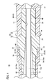
- the medical needle 10 includes a tubular needle body 12 having a sharp needle tip 11 at the tip and a resin needle hub 14 provided on the base end side of the needle body 12.
- a resin protector 16 (cap) that covers the needle body 12 while being attached to the needle hub 14 is provided.
- the constituent material of the needle body 12 examples include metal materials such as stainless steel, aluminum or aluminum alloy, titanium or titanium alloy.
- the needle body 12 is a circular tubular member having a lumen 12a (see FIG. 3) that serves as a flow path for a body fluid such as blood or an infusion solution.
- a blade surface 12b that is inclined with respect to the axial direction of the needle body 12 is formed at the tip end portion of the needle body 12.
- the blade surface 12b is formed with an opening 12c that functions as an inlet / outlet for liquid.
- the needle hub 14 has a needle holding member 18 in which a needle insertion hole 17 into which the base end side of the needle body 12 is inserted is formed, and a hollow operating member 20 provided at the base end portion of the needle holding member 18. ..
- the needle holding member 18 is a single member (integrally molded product) integrally injection-molded with a resin material.
- the needle holding member 18 is preferably made of a resin material having good bondability (adhesiveness) of the needle body 12.
- the constituent material of the needle holding member 18 is preferably polycarbonate (PC) or polypropylene (PP).
- the operating member 20 is a single member (integrally molded product) integrally injection-molded with a resin material.
- the operating member 20 is preferably made of a resin material that prevents the user's fingers from slipping. Further, the operating member 20 is preferably made of the same resin material as the constituent material of the tube 100 (see FIG. 3) connected to the base end portion.
- the constituent material of the operating member 20 is preferably polyvinyl chloride (PVC).
- the constituent materials of the needle holding member 18 and the operating member 20 may be made of the same resin material as each other.
- the needle hub 14 may be a single member (integrally molded product) integrally injection-molded with a resin material.
- the constituent materials of the needle holding member 18 and the operating member 20 are not limited to those described above, and may be, for example, polyethylene, polyolefin, polyurethane, polyamide, polyester, polybutadiene, polyacetal or the like.
- the needle holding member 18 is formed in a cylindrical shape.
- the needle holding member 18 is provided between the first mounting portion 22 and the second mounting portion 24, which are inserted into the lumen 16a of the protector 16 in the unopened state of the protector 16, and the base end portion of the second mounting portion 24.
- a portion 26 and a proximal end convex portion 28 protruding from the intermediate portion 26 in the proximal end direction are included.
- the first mounting portion 22 forms the tip portion of the needle holding member 18.
- the second mounting portion 24 is provided at the base end portion of the first mounting portion 22.
- the outer diameter of the second mounting portion 24 is larger than the outer diameter of the first mounting portion 22.
- a rotation mechanism 30 for relatively rotating the protector 16 and the needle hub 14 in the circumferential direction when the protector 16 is opened is provided.
- the rotation mechanism 30 has two screw-like protrusions 32 (threads) that are inclined in the proximal direction toward the circumferential direction of the second mounting portion 24.
- Each screw-shaped protrusion 32 is formed to be narrower in the radial direction of the second mounting portion 24 (see FIG. 4). That is, each screw-shaped protrusion 32 has a triangular cross section.
- the two screw-shaped protrusions 32 are located 180 ° apart in the circumferential direction of the second mounting portion 24.
- the two threaded protrusions 32 are located so as not to overlap each other in the axial direction of the needle hub 14.
- Each screw-shaped protrusion 32 is formed to be narrower toward both ends (see FIGS. 2 and 6B).
- the intermediate portion 26 is exposed to the outside of the protector 16 in an unopened state (see FIG. 1).
- the outer diameter of the intermediate portion 26 is larger than the outer diameter of the second mounting portion 24. That is, the intermediate portion 26 is formed with a tip-side stepped surface 34 that directs the tip direction.
- the tip side step surface 34 is an facing surface facing the base end surface of the protector 16 in an unopened state of the protector 16.
- the tip side step surface 34 is provided with one convex portion 36 protruding in the tip direction.
- the convex portion 36 is integrally connected to the outer peripheral surface of the second mounting portion 24.
- the convex portion 36 is formed in a square shape (or rectangular shape) when viewed from the outer peripheral surface side of the intermediate portion 26.
- the thickness dimension of the convex portion 36 (the dimension along the radial direction of the intermediate portion 26) is the step of the intermediate portion 26 with respect to the second mounting portion 24 (the outer peripheral surface of the second mounting portion 24 and the outer peripheral surface of the intermediate portion 26). It has the same dimensions as (interval).
- the thickness dimension of the convex portion 36 is the same over the entire length along the axial direction of the needle hub 14.
- the width dimension of the convex portion 36 (dimension along the circumferential direction of the intermediate portion 26) is substantially the same as the thickness dimension of the convex portion 36.
- the shape and size of the convex portion 36 can be changed as appropriate.
- the convex portion 36 and the blade surface 12b coincide with each other in the circumferential position of the needle body 12 (see FIG. 2). That is, the medical needle 10 is configured so that the blade surface 12b faces upward when the convex portion 36 faces upward. In other words, the convex portion 36 functions as a marker indicating the orientation of the blade surface 12b.
- the outer diameter of the base end convex portion 28 is smaller than the outer diameter of the intermediate portion 26. That is, the intermediate portion 26 is formed with a base end side stepped surface 38 that directs the base end direction. The base end side stepped surface 38 is in contact with the tip surface of the operating member 20.
- the needle insertion hole 17 extends over the entire length of the needle holding member 18. The base end side of the needle body 12 is adhered to the wall surface forming the needle insertion hole 17 with an adhesive (for example, an ultraviolet curable resin) (not shown).
- the operating member 20 forms a portion held by the user with a finger when using the medical needle 10.
- the outer shape of the operating member 20 is formed in a circular shape (perfect circular shape). However, the outer shape of the operating member 20 may be formed into an elliptical shape or a polygonal shape (triangular shape, quadrangular shape, etc.).
- An uneven non-slip portion 42 is formed on the outer peripheral surface of the operating member 20.
- the non-slip portion 42 is formed by alternately providing grooves 44 and protrusions 46 extending along the axial direction of the operating member 20 in the circumferential direction.
- the configuration of the non-slip portion 42 can be changed as appropriate.
- the tip surface of the operating member 20 is formed with a tip-side recess 48 into which the base end portion (base end convex portion 28) of the needle holding member 18 is fitted.
- the inner peripheral surface forming the distal end side concave portion 48 is firmly fixed to the outer peripheral surface of the proximal end convex portion 28 due to the difference in heat shrinkage between the needle holding member 18 and the operating member 20.
- the base end convex portion 28 may be press-fitted into the tip end side concave portion 48.
- the base end convex portion 28 may be adhered to the inner peripheral surface forming the tip end side concave portion 48 with an adhesive (not shown).
- a base end side recess 50 into which the tube 100 is inserted is formed on the base end surface of the operating member 20.
- the operating member 20 fits the proximal convex portion 28 into the distal concave portion 48 and inserts the tube 100 into the proximal concave portion 50, and holds the inner cavity 12a of the needle body 12 and the inner cavity 100a of the tube 100. Communication holes 51 that communicate with each other are formed.
- the protector 16 is a tubular member whose tip is closed and whose base end is open.
- the protector 16 is a single member (integrally molded product) integrally injection-molded by a resin material.
- the protector 16 is made of a resin material that is softer than the needle holding member 18. That is, the convex portion 36 has a higher hardness than the protector 16.
- the constituent material of the protector 16 include polypropylene, polycarbonate, olefin elastomer, polyvinyl chloride, polyethylene, polyolefin, polyurethane, polyamide, polyester, polybutadiene, polyacetal and the like.
- the lumen 16a of the protector 16 communicates with the tip hole 52 into which the tip side of the needle body 12 is inserted, the first mounting hole 54 communicating with the base end side of the tip hole 52, and the base end side of the first mounting hole 54.
- the second mounting hole 56 is included.
- the hole diameter of the first mounting hole 54 is larger than the hole diameter of the tip hole 52.
- the first mounting portion 22 is inserted into the first mounting hole 54 in the unopened state of the protector 16.
- the second mounting hole 56 is open at the base end of the protector 16.
- the hole diameter of the second mounting hole 56 is larger than the hole diameter of the first mounting hole 54.
- Two screw-shaped grooves 58 are formed by biting into the inner peripheral surface forming the second mounting hole 56.
- the second mounting portion 24 is inserted into the second mounting hole 56 in the unopened state of the protector 16.
- a concave portion 60 is formed on the base end surface of the protector 16 by the convex portion 36 of the needle hub 14 biting into the base end surface.
- the concave portion 60 has a shape corresponding to the shape of the convex portion 36. That is, the recess 60 is formed in a square shape (rectangular shape).
- the two side surfaces 60a and 60b forming the recess 60 extend along the axial direction of the protector 16 (see FIG. 6B).
- the method for manufacturing the medical needle 10 includes a needle hub molding step, a needle joining step, a protector molding step (cap molding step), and a mounting step.
- the needle holding member 18 having the convex portion 36 and the operating member 20 are separately injection-molded, and the base of the needle holding member 18 is formed in the tip-side recess 48 of the operating member 20.
- the end convex portion 28 is fitted.
- the needle joining step step S2 in FIG. 5
- the base end side of the needle 12 is adhered to the wall surface forming the needle insertion hole 17 with an adhesive.
- the protector molding step step S3 in FIG. 5
- the protector 16 is injection molded. At this time, the protector 16 is not formed with the recess 60 and the screw groove 58 described above.
- the needle body 12 is inserted into the lumen 16a of the protector 16 and mounted on the needle hub 14.
- the convex portion 36 of the needle hub 14 is press-fitted into the base end surface of the protector 16.
- a concave portion 60 having a shape corresponding to the shape of the convex portion 36 is formed on the base end surface of the protector 16.
- the screw-shaped protrusion 32 provided on the outer peripheral surface of the second mounting portion 24 bites into the inner peripheral surface forming the second mounting hole 56 (see FIG. 4). Therefore, a screw-shaped groove 58 having a shape corresponding to the shape of the screw-shaped protrusion 32 is formed on the inner peripheral surface forming the second mounting hole 56. Further, the base end surface of the protector 16 comes into contact with or approaches the tip end side step surface 34 of the needle hub 14. As a result, the medical needle 10 is manufactured.
- the opening operation of the protector 16 of the unopened medical needle 10 will be described.
- the screw-shaped protrusion 32 bites into the inner peripheral surface forming the second mounting hole 56. Therefore, even if the user pulls the protector 16 toward the tip end side with respect to the needle hub 14, the protector 16 is not opened.
- the user When opening the protector 16 of the medical needle 10, the user rotates the needle hub 14 and the protector 16 relative to each other in the circumferential direction of the needle body 12, as shown in FIG. 7A. Then, the threaded protrusion 32 of the protector 16 rotates with respect to the inner peripheral surface forming the second mounting hole 56 of the needle hub 14.
- one side surface 60b forming the concave portion 60 is plastically deformed so as to be expanded in the circumferential direction by the convex portion 36. That is, the side surface 60b extends so as to be inclined in the circumferential direction toward the base end direction of the protector 16. Then, when the convex portion 36 is separated from the concave portion 60 and the screw-shaped protrusion 32 is separated from the second mounting hole 56, the user pulls out the protector 16 toward the tip of the needle hub 14 (see FIG. 7B). As a result, the protector 16 is opened and the needle body 12 is exposed from the protector 16.
- the shape of the recess 60 is deformed. That is, the shape of the recess 60 of the protector 16 changes from a square (or a rectangle) to a trapezoid. In other words, the orientation (position) of the side surface 60b forming the recess 60 changes. Therefore, as shown in FIG. 8, when the protector 16 once opened is reattached to the needle hub 14, a triangular gap S is formed with the convex portion 36 inserted into the concave portion 60. Therefore, the user can easily distinguish between the unopened state and the opened state of the protector 16. That is, the medical needle 10 has a good tamper proof property.
- the medical needle 10 and the method for manufacturing the medical needle 10 according to the present embodiment have the following effects.
- the protector 16 is opened by the relative rotation of the protector 16 and the needle hub 14 in the circumferential direction.
- the needle hub 14 is provided with a convex portion 36
- the protector 16 is provided with a concave portion 60 into which the convex portion 36 is inserted in an unopened state in which the protector 16 is attached to the needle hub 14.
- the shape of the recess 60 changes irreversibly due to the relative rotation of the protector 16 and the needle hub 14 when the protector 16 is opened.
- the shape of the recess 60 changes irreversibly. Therefore, even when the protector 16 once opened is reattached to the needle hub 14, the unopened state and the opened state of the protector 16 can be easily discriminated by visually recognizing the changed shape of the recess 60. Can be done.
- the wall surface (side surface 60b) forming the recess 60 is plastically deformed by the relative rotation of the protector 16 and the needle hub 14.
- the convex portion 36 has a higher hardness than the protector 16.
- the wall surface (side surface 60b) forming the concave portion 60 by the convex portion 36 can be effectively plastically deformed.
- the needle hub 14 is provided with a tip-side stepped surface 34 facing the base end surface of the protector 16 in an unopened state, the convex portion 36 projects from the tip-side stepped surface 34 toward the tip end, and the concave portion 60 is the protector 16. It is formed on the base end surface of.
- the configuration of the protector 16 and the needle hub 14 can be simplified.
- a blade surface 12b that is inclined with respect to the axial direction of the needle body 12 is formed at the tip end portion of the needle body 12, and a convex portion 36 and a concave portion 60 are provided one by one, and a convex portion provided on the needle hub 14 is provided.
- the positions of the needle body 12 in the circumferential direction of 36 and the blade surface 12b coincide with each other.
- the orientation of the blade surface 12b can be easily known by the convex portion 36 provided on the needle hub 14.
- the method for manufacturing the medical needle 10 includes a needle hub molding step of molding the needle hub 14 provided with the convex portion 36 and joining the base end side of the needle body 12 to the needle hub 14 formed in the needle hub molding step.
- a needle joining step a protector molding step of molding the protector 16, a mounting step of mounting the protector 16 molded in the protector molding step on the needle hub 14 to which the needle body 12 is joined in the needle joining step, and a mounting step.
- the convex portion 36 is press-fitted into the base end surface of the protector 16 to form a concave portion 60 on the base end surface of the protector 16.
- the protector 16 is opened by the relative rotation of the protector 16 and the needle hub 14 in the circumferential direction, and the recess 60 is irreversibly shaped by the relative rotation of the protector 16 and the needle hub 14 when the protector 16 is opened. Changes.
- the medical needle 10 is not limited to the above-described configuration.
- the convex portion 36 may be plastically deformed by the relative rotation of the protector 16 and the needle hub 14 when the protector 16 is opened. Further, the convex portion 36 may hit the wall surface (side surface 60b) forming the concave portion 60 when the protector 16 is opened and be damaged to be separated from the needle hub 14. In this case, the wall surface (side surface 60b) forming the recess 60 may or may not be plastically deformed. With such a configuration, it is possible to more easily distinguish between the unopened state and the opened state of the protector 16. A plurality of sets of the concave portion 60 and the convex portion 36 may be provided.
- a recess 60 is formed on the base end surface of the protector 16 in the protector molding step, and the convex portion 36 of the needle hub 14 is press-fitted into the recess 60 of the protector 16 in the mounting step. May be good. Further, in the protector forming step, a screw-shaped groove 58 in which the screw-shaped protrusion 32 is screwed may be formed on the inner peripheral surface of the second mounting hole 56.
- the medical needle according to the present invention may be provided with a convex portion protruding in the proximal direction on the proximal end surface of the protector, and may be provided with a concave portion into which the convex portion is inserted in the needle hub.
- at least one of the wall surface and the convex portion forming the concave portion is plastically deformed by the relative rotation of the protector and the needle hub when the protector is opened.
- a medical needle (10) comprising a hollow cap (16), wherein the cap is opened by relative rotation of the cap and the needle hub in the circumferential direction of the needle hub and the needle hub.
- a convex portion (36) is provided on one of the caps, and the convex portion is inserted into either the needle hub or the cap in an unopened state in which the cap is attached to the needle hub.
- the concave portion (60) is provided, and at least one of the concave portion and the convex portion is irreversibly changed in shape due to the relative rotation of the cap and the needle hub when the cap is opened. It is disclosed.
- the needle hub may be provided with the convex portion
- the cap may be provided with the concave portion
- the wall surface forming the recess may be plastically deformed by the relative rotation of the cap and the needle hub.
- the convex portion may have a higher hardness than the cap.
- the needle hub is provided with a facing surface facing the base end surface of the cap in the unopened state, the convex portion projects from the facing surface toward the tip end, and the concave portion , May be formed on the base end surface of the cap.
- a blade surface (12b) inclined with respect to the axial direction of the needle body is formed at the tip end portion of the needle body, and the convex portion and the concave portion are provided one by one.
- the convex portion or the concave portion provided on the needle hub and the blade surface may be aligned with each other in the circumferential direction of the needle body.
- the above-described embodiment includes a needle body, a hollow needle hub fixed to the base end side of the needle body, and a hollow cap that covers the tip end side of the needle body while being attached to the needle hub.
- a method for manufacturing a medical needle comprising: a needle hub molding step of molding the needle hub provided with a convex portion, and a base end side of the needle body on the needle hub molded in the needle hub molding step.
- the cap formed in the cap forming step is attached to the needle hub to which the needles are joined in the needle joining step, the cap forming step of forming the cap, and the needle joining step.
- a concave portion is formed on the base end surface of the cap by press-fitting the convex portion into the base end surface of the cap, and the cap is of the cap and the needle hub.
- the seal is opened by the relative rotation of the needle body in the circumferential direction, and at least one of the concave portion and the convex portion is irreversibly changed in shape by the relative rotation of the cap and the needle hub when the cap is opened.
Landscapes
- Health & Medical Sciences (AREA)
- Vascular Medicine (AREA)
- Engineering & Computer Science (AREA)
- Anesthesiology (AREA)
- Biomedical Technology (AREA)
- Heart & Thoracic Surgery (AREA)
- Hematology (AREA)
- Life Sciences & Earth Sciences (AREA)
- Animal Behavior & Ethology (AREA)
- General Health & Medical Sciences (AREA)
- Public Health (AREA)
- Veterinary Medicine (AREA)
- Infusion, Injection, And Reservoir Apparatuses (AREA)
Abstract
Dans une aiguille médicale (10) selon la présente invention, une partie en saillie (36) est prévue pour l'un quelconque parmi une embase d'aiguille (14) et un capuchon (16), et une partie évidée, dans laquelle la partie en saillie (36) est insérée alors que le capuchon (16) n'est pas ouvert, est prévue à l'autre parmi l'embase d'aiguille (14) et le capuchon (16), et au moins une parmi la partie évidée (60) et la partie saillante (36) change de forme de manière irréversible par la rotation relative du capuchon et de l'embase d'aiguille (14). L'invention concerne également un procédé de fabrication d'une aiguille médicale (10) comportant une étape de fixation pour former une partie évidée (60) sur la surface d'extrémité de base du capuchon (16) par pression de la partie de saillie (36) dans la surface d'extrémité de base du capuchon (16).
Priority Applications (1)
| Application Number | Priority Date | Filing Date | Title |
|---|---|---|---|
| JP2021548820A JPWO2021060054A1 (fr) | 2019-09-24 | 2020-09-14 |
Applications Claiming Priority (2)
| Application Number | Priority Date | Filing Date | Title |
|---|---|---|---|
| JP2019-172776 | 2019-09-24 | ||
| JP2019172776 | 2019-09-24 |
Publications (1)
| Publication Number | Publication Date |
|---|---|
| WO2021060054A1 true WO2021060054A1 (fr) | 2021-04-01 |
Family
ID=75166634
Family Applications (1)
| Application Number | Title | Priority Date | Filing Date |
|---|---|---|---|
| PCT/JP2020/034754 WO2021060054A1 (fr) | 2019-09-24 | 2020-09-14 | Aiguille médicale et procédé de fabrication d'aiguille médicale |
Country Status (2)
| Country | Link |
|---|---|
| JP (1) | JPWO2021060054A1 (fr) |
| WO (1) | WO2021060054A1 (fr) |
Citations (3)
| Publication number | Priority date | Publication date | Assignee | Title |
|---|---|---|---|---|
| JPS52129192U (fr) * | 1976-03-29 | 1977-10-01 | ||
| JPH0396852U (fr) * | 1990-01-24 | 1991-10-03 | ||
| US20060178627A1 (en) * | 2004-05-29 | 2006-08-10 | Bünder Glas GmbH | Syringe tip cap and method for producing a syringe tip cap |
-
2020
- 2020-09-14 JP JP2021548820A patent/JPWO2021060054A1/ja active Pending
- 2020-09-14 WO PCT/JP2020/034754 patent/WO2021060054A1/fr active Application Filing
Patent Citations (3)
| Publication number | Priority date | Publication date | Assignee | Title |
|---|---|---|---|---|
| JPS52129192U (fr) * | 1976-03-29 | 1977-10-01 | ||
| JPH0396852U (fr) * | 1990-01-24 | 1991-10-03 | ||
| US20060178627A1 (en) * | 2004-05-29 | 2006-08-10 | Bünder Glas GmbH | Syringe tip cap and method for producing a syringe tip cap |
Also Published As
| Publication number | Publication date |
|---|---|
| JPWO2021060054A1 (fr) | 2021-04-01 |
Similar Documents
| Publication | Publication Date | Title |
|---|---|---|
| US7247148B2 (en) | Protector and storage needle assembly | |
| US8096525B2 (en) | Swabbable needle-free injection port valve system with zero fluid displacement | |
| EP2110149B1 (fr) | Assemblage d'aiguille à ailettes et couvercle fragile | |
| US20100268163A1 (en) | Modular introducer and exchange sheath | |
| EP2441490A1 (fr) | Port sous-cutané implantable et son procédé de production | |
| US10166342B2 (en) | Recoil reducing needle shields | |
| JP6934873B2 (ja) | カテーテル組立体 | |
| WO2007005584A1 (fr) | Gaines d'introduction et d'echange | |
| WO2021060054A1 (fr) | Aiguille médicale et procédé de fabrication d'aiguille médicale | |
| JP3798928B2 (ja) | 内視鏡用処置具のチューブと口金の接続構造 | |
| WO2012043247A1 (fr) | Aiguille de perforation pour l'injection d'un ciment osseux et son procédé de fabrication | |
| JP7126491B2 (ja) | カテーテル | |
| WO2014147815A1 (fr) | Cathéter pour aspiration de matière étrangère dans un vaisseau sanguin | |
| US20220062563A1 (en) | Hypodermic interface assembly | |
| US20220203073A1 (en) | Catheter assembly | |
| US20220241516A1 (en) | Pen needle | |
| WO2020189466A1 (fr) | Ensemble cathéter | |
| JP5419515B2 (ja) | カテーテル固定具およびそれを備えた薬液注入ポートセット | |
| JP3747947B2 (ja) | イントロデューサー | |
| JP6978885B2 (ja) | カテーテル組立体 | |
| WO2021060053A1 (fr) | Aiguille médicale et procédé de fabrication d'aiguille médicale | |
| JP2020121030A (ja) | 医療用弁体および医療用挿入補助具 | |
| WO2020189467A1 (fr) | Ensemble cathéter | |
| JP3691091B2 (ja) | イントロデューサー | |
| WO2020116363A1 (fr) | Ensemble cathéter et corps à demeure de cathéter |
Legal Events
| Date | Code | Title | Description |
|---|---|---|---|
| 121 | Ep: the epo has been informed by wipo that ep was designated in this application |
Ref document number: 20869213 Country of ref document: EP Kind code of ref document: A1 |
|
| ENP | Entry into the national phase |
Ref document number: 2021548820 Country of ref document: JP Kind code of ref document: A |
|
| NENP | Non-entry into the national phase |
Ref country code: DE |
|
| 122 | Ep: pct application non-entry in european phase |
Ref document number: 20869213 Country of ref document: EP Kind code of ref document: A1 |