WO2021060054A1 - Medical needle and method for manufacturing medical needle - Google Patents
Medical needle and method for manufacturing medical needle Download PDFInfo
- Publication number
- WO2021060054A1 WO2021060054A1 PCT/JP2020/034754 JP2020034754W WO2021060054A1 WO 2021060054 A1 WO2021060054 A1 WO 2021060054A1 JP 2020034754 W JP2020034754 W JP 2020034754W WO 2021060054 A1 WO2021060054 A1 WO 2021060054A1
- Authority
- WO
- WIPO (PCT)
- Prior art keywords
- needle
- cap
- needle hub
- convex portion
- medical
- Prior art date
Links
Images


Classifications
-
- A—HUMAN NECESSITIES
- A61—MEDICAL OR VETERINARY SCIENCE; HYGIENE
- A61M—DEVICES FOR INTRODUCING MEDIA INTO, OR ONTO, THE BODY; DEVICES FOR TRANSDUCING BODY MEDIA OR FOR TAKING MEDIA FROM THE BODY; DEVICES FOR PRODUCING OR ENDING SLEEP OR STUPOR
- A61M5/00—Devices for bringing media into the body in a subcutaneous, intra-vascular or intramuscular way; Accessories therefor, e.g. filling or cleaning devices, arm-rests
- A61M5/14—Infusion devices, e.g. infusing by gravity; Blood infusion; Accessories therefor
- A61M5/158—Needles for infusions; Accessories therefor, e.g. for inserting infusion needles, or for holding them on the body
-
- A—HUMAN NECESSITIES
- A61—MEDICAL OR VETERINARY SCIENCE; HYGIENE
- A61M—DEVICES FOR INTRODUCING MEDIA INTO, OR ONTO, THE BODY; DEVICES FOR TRANSDUCING BODY MEDIA OR FOR TAKING MEDIA FROM THE BODY; DEVICES FOR PRODUCING OR ENDING SLEEP OR STUPOR
- A61M5/00—Devices for bringing media into the body in a subcutaneous, intra-vascular or intramuscular way; Accessories therefor, e.g. filling or cleaning devices, arm-rests
- A61M5/178—Syringes
- A61M5/31—Details
- A61M5/32—Needles; Details of needles pertaining to their connection with syringe or hub; Accessories for bringing the needle into, or holding the needle on, the body; Devices for protection of needles
-
- A—HUMAN NECESSITIES
- A61—MEDICAL OR VETERINARY SCIENCE; HYGIENE
- A61M—DEVICES FOR INTRODUCING MEDIA INTO, OR ONTO, THE BODY; DEVICES FOR TRANSDUCING BODY MEDIA OR FOR TAKING MEDIA FROM THE BODY; DEVICES FOR PRODUCING OR ENDING SLEEP OR STUPOR
- A61M5/00—Devices for bringing media into the body in a subcutaneous, intra-vascular or intramuscular way; Accessories therefor, e.g. filling or cleaning devices, arm-rests
- A61M5/50—Devices for bringing media into the body in a subcutaneous, intra-vascular or intramuscular way; Accessories therefor, e.g. filling or cleaning devices, arm-rests having means for preventing re-use, or for indicating if defective, used, tampered with or unsterile
Definitions
- the present invention relates to a medical needle and a method for manufacturing a medical needle.
- Japanese Patent Application Laid-Open No. 2017-12638 describes a needle body, a hollow needle hub fixed to the base end side of the needle body, and a cap that covers the tip end side of the needle body while being attached to the needle hub.
- a medical needle with a protector is disclosed.
- the cap has a plurality of fractured portions that connect the middle portion of the cap and the base end portion of the cap to each other and are arranged at intervals in the circumferential direction, and the cap is opened by twisting the fractured portions by the user. ..
- the present invention has been made in consideration of such a problem, and provides a medical needle and a method for manufacturing a medical needle, which can easily distinguish between an unopened state and an opened state of a cap. With the goal.
- One aspect of the present invention is a needle body, a hollow needle hub fixed to the base end side of the needle body, and a hollow cap that covers the tip end side of the needle body while being attached to the needle hub.
- the cap is opened by relative rotation of the cap and the needle hub in the circumferential direction, and is convex to either the needle hub or the cap.
- a portion is provided, and one of the needle hub and the cap is provided with a recess into which the convex portion is inserted in an unopened state in which the cap is attached to the needle hub.
- At least one is a medical needle whose shape changes irreversibly due to the relative rotation of the cap and the needle hub when the cap is opened.
- Another aspect of the present invention includes a needle body, a hollow needle hub fixed to the base end side of the needle body, and a hollow shape covering the tip end side of the needle body while being attached to the needle hub.
- a method for manufacturing a medical needle including a cap, wherein a needle hub forming step of forming the needle hub provided with a convex portion and a needle hub formed by the needle hub forming step of the needle body are formed on the needle hub.
- It has a mounting step of mounting a cap, and in the mounting step, a concave portion is formed on the base end surface of the cap by press-fitting the convex portion into the base end surface of the cap, and the cap is formed of the cap and the cap.
- the needle hub is opened by the relative rotation of the needle body in the circumferential direction, and at least one of the concave portion and the convex portion is irreversibly opened by the relative rotation of the cap and the needle hub when the cap is opened.
- the shape of at least one of the concave portion and the convex portion is irreversibly changed. Therefore, even when the cap once opened is reattached to the needle hub, the unopened state and the opened state of the cap can be easily determined by visually recognizing at least one of the changed shapes of the concave portion and the convex portion. It can be determined.
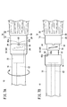
- FIG. 6A is a first explanatory view of the mounting process
- FIG. 6B is a second explanatory view of the mounting process
- 7A is a first explanatory view of the opening operation of the protector of the medical needle of FIG. 1
- FIG. 7B is a second explanatory view of the opening operation of the protector of the medical needle of FIG. It is explanatory drawing which shows the state which the protector which opened once was reattached to the needle hub.
- the medical needle 10 is configured as a blood collection needle for collecting blood from a living body (vein).
- the medical needle 10 is not limited to the blood collection needle, and may be, for example, an indwelling needle for injecting an infusion solution into the body.
- the medical needle 10 includes a tubular needle body 12 having a sharp needle tip 11 at the tip and a resin needle hub 14 provided on the base end side of the needle body 12.
- a resin protector 16 (cap) that covers the needle body 12 while being attached to the needle hub 14 is provided.
- the constituent material of the needle body 12 examples include metal materials such as stainless steel, aluminum or aluminum alloy, titanium or titanium alloy.
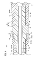
- the needle body 12 is a circular tubular member having a lumen 12a (see FIG. 3) that serves as a flow path for a body fluid such as blood or an infusion solution.
- a blade surface 12b that is inclined with respect to the axial direction of the needle body 12 is formed at the tip end portion of the needle body 12.
- the blade surface 12b is formed with an opening 12c that functions as an inlet / outlet for liquid.
- the needle hub 14 has a needle holding member 18 in which a needle insertion hole 17 into which the base end side of the needle body 12 is inserted is formed, and a hollow operating member 20 provided at the base end portion of the needle holding member 18. ..
- the needle holding member 18 is a single member (integrally molded product) integrally injection-molded with a resin material.
- the needle holding member 18 is preferably made of a resin material having good bondability (adhesiveness) of the needle body 12.
- the constituent material of the needle holding member 18 is preferably polycarbonate (PC) or polypropylene (PP).
- the operating member 20 is a single member (integrally molded product) integrally injection-molded with a resin material.
- the operating member 20 is preferably made of a resin material that prevents the user's fingers from slipping. Further, the operating member 20 is preferably made of the same resin material as the constituent material of the tube 100 (see FIG. 3) connected to the base end portion.
- the constituent material of the operating member 20 is preferably polyvinyl chloride (PVC).
- the constituent materials of the needle holding member 18 and the operating member 20 may be made of the same resin material as each other.
- the needle hub 14 may be a single member (integrally molded product) integrally injection-molded with a resin material.
- the constituent materials of the needle holding member 18 and the operating member 20 are not limited to those described above, and may be, for example, polyethylene, polyolefin, polyurethane, polyamide, polyester, polybutadiene, polyacetal or the like.
- the needle holding member 18 is formed in a cylindrical shape.
- the needle holding member 18 is provided between the first mounting portion 22 and the second mounting portion 24, which are inserted into the lumen 16a of the protector 16 in the unopened state of the protector 16, and the base end portion of the second mounting portion 24.
- a portion 26 and a proximal end convex portion 28 protruding from the intermediate portion 26 in the proximal end direction are included.
- the first mounting portion 22 forms the tip portion of the needle holding member 18.
- the second mounting portion 24 is provided at the base end portion of the first mounting portion 22.
- the outer diameter of the second mounting portion 24 is larger than the outer diameter of the first mounting portion 22.
- a rotation mechanism 30 for relatively rotating the protector 16 and the needle hub 14 in the circumferential direction when the protector 16 is opened is provided.
- the rotation mechanism 30 has two screw-like protrusions 32 (threads) that are inclined in the proximal direction toward the circumferential direction of the second mounting portion 24.
- Each screw-shaped protrusion 32 is formed to be narrower in the radial direction of the second mounting portion 24 (see FIG. 4). That is, each screw-shaped protrusion 32 has a triangular cross section.
- the two screw-shaped protrusions 32 are located 180 ° apart in the circumferential direction of the second mounting portion 24.
- the two threaded protrusions 32 are located so as not to overlap each other in the axial direction of the needle hub 14.
- Each screw-shaped protrusion 32 is formed to be narrower toward both ends (see FIGS. 2 and 6B).
- the intermediate portion 26 is exposed to the outside of the protector 16 in an unopened state (see FIG. 1).
- the outer diameter of the intermediate portion 26 is larger than the outer diameter of the second mounting portion 24. That is, the intermediate portion 26 is formed with a tip-side stepped surface 34 that directs the tip direction.
- the tip side step surface 34 is an facing surface facing the base end surface of the protector 16 in an unopened state of the protector 16.
- the tip side step surface 34 is provided with one convex portion 36 protruding in the tip direction.
- the convex portion 36 is integrally connected to the outer peripheral surface of the second mounting portion 24.
- the convex portion 36 is formed in a square shape (or rectangular shape) when viewed from the outer peripheral surface side of the intermediate portion 26.
- the thickness dimension of the convex portion 36 (the dimension along the radial direction of the intermediate portion 26) is the step of the intermediate portion 26 with respect to the second mounting portion 24 (the outer peripheral surface of the second mounting portion 24 and the outer peripheral surface of the intermediate portion 26). It has the same dimensions as (interval).
- the thickness dimension of the convex portion 36 is the same over the entire length along the axial direction of the needle hub 14.
- the width dimension of the convex portion 36 (dimension along the circumferential direction of the intermediate portion 26) is substantially the same as the thickness dimension of the convex portion 36.
- the shape and size of the convex portion 36 can be changed as appropriate.
- the convex portion 36 and the blade surface 12b coincide with each other in the circumferential position of the needle body 12 (see FIG. 2). That is, the medical needle 10 is configured so that the blade surface 12b faces upward when the convex portion 36 faces upward. In other words, the convex portion 36 functions as a marker indicating the orientation of the blade surface 12b.
- the outer diameter of the base end convex portion 28 is smaller than the outer diameter of the intermediate portion 26. That is, the intermediate portion 26 is formed with a base end side stepped surface 38 that directs the base end direction. The base end side stepped surface 38 is in contact with the tip surface of the operating member 20.
- the needle insertion hole 17 extends over the entire length of the needle holding member 18. The base end side of the needle body 12 is adhered to the wall surface forming the needle insertion hole 17 with an adhesive (for example, an ultraviolet curable resin) (not shown).
- the operating member 20 forms a portion held by the user with a finger when using the medical needle 10.
- the outer shape of the operating member 20 is formed in a circular shape (perfect circular shape). However, the outer shape of the operating member 20 may be formed into an elliptical shape or a polygonal shape (triangular shape, quadrangular shape, etc.).
- An uneven non-slip portion 42 is formed on the outer peripheral surface of the operating member 20.
- the non-slip portion 42 is formed by alternately providing grooves 44 and protrusions 46 extending along the axial direction of the operating member 20 in the circumferential direction.
- the configuration of the non-slip portion 42 can be changed as appropriate.
- the tip surface of the operating member 20 is formed with a tip-side recess 48 into which the base end portion (base end convex portion 28) of the needle holding member 18 is fitted.
- the inner peripheral surface forming the distal end side concave portion 48 is firmly fixed to the outer peripheral surface of the proximal end convex portion 28 due to the difference in heat shrinkage between the needle holding member 18 and the operating member 20.
- the base end convex portion 28 may be press-fitted into the tip end side concave portion 48.
- the base end convex portion 28 may be adhered to the inner peripheral surface forming the tip end side concave portion 48 with an adhesive (not shown).
- a base end side recess 50 into which the tube 100 is inserted is formed on the base end surface of the operating member 20.
- the operating member 20 fits the proximal convex portion 28 into the distal concave portion 48 and inserts the tube 100 into the proximal concave portion 50, and holds the inner cavity 12a of the needle body 12 and the inner cavity 100a of the tube 100. Communication holes 51 that communicate with each other are formed.
- the protector 16 is a tubular member whose tip is closed and whose base end is open.
- the protector 16 is a single member (integrally molded product) integrally injection-molded by a resin material.
- the protector 16 is made of a resin material that is softer than the needle holding member 18. That is, the convex portion 36 has a higher hardness than the protector 16.
- the constituent material of the protector 16 include polypropylene, polycarbonate, olefin elastomer, polyvinyl chloride, polyethylene, polyolefin, polyurethane, polyamide, polyester, polybutadiene, polyacetal and the like.
- the lumen 16a of the protector 16 communicates with the tip hole 52 into which the tip side of the needle body 12 is inserted, the first mounting hole 54 communicating with the base end side of the tip hole 52, and the base end side of the first mounting hole 54.
- the second mounting hole 56 is included.
- the hole diameter of the first mounting hole 54 is larger than the hole diameter of the tip hole 52.
- the first mounting portion 22 is inserted into the first mounting hole 54 in the unopened state of the protector 16.
- the second mounting hole 56 is open at the base end of the protector 16.
- the hole diameter of the second mounting hole 56 is larger than the hole diameter of the first mounting hole 54.
- Two screw-shaped grooves 58 are formed by biting into the inner peripheral surface forming the second mounting hole 56.
- the second mounting portion 24 is inserted into the second mounting hole 56 in the unopened state of the protector 16.
- a concave portion 60 is formed on the base end surface of the protector 16 by the convex portion 36 of the needle hub 14 biting into the base end surface.
- the concave portion 60 has a shape corresponding to the shape of the convex portion 36. That is, the recess 60 is formed in a square shape (rectangular shape).
- the two side surfaces 60a and 60b forming the recess 60 extend along the axial direction of the protector 16 (see FIG. 6B).
- the method for manufacturing the medical needle 10 includes a needle hub molding step, a needle joining step, a protector molding step (cap molding step), and a mounting step.
- the needle holding member 18 having the convex portion 36 and the operating member 20 are separately injection-molded, and the base of the needle holding member 18 is formed in the tip-side recess 48 of the operating member 20.
- the end convex portion 28 is fitted.
- the needle joining step step S2 in FIG. 5
- the base end side of the needle 12 is adhered to the wall surface forming the needle insertion hole 17 with an adhesive.
- the protector molding step step S3 in FIG. 5
- the protector 16 is injection molded. At this time, the protector 16 is not formed with the recess 60 and the screw groove 58 described above.
- the needle body 12 is inserted into the lumen 16a of the protector 16 and mounted on the needle hub 14.
- the convex portion 36 of the needle hub 14 is press-fitted into the base end surface of the protector 16.
- a concave portion 60 having a shape corresponding to the shape of the convex portion 36 is formed on the base end surface of the protector 16.
- the screw-shaped protrusion 32 provided on the outer peripheral surface of the second mounting portion 24 bites into the inner peripheral surface forming the second mounting hole 56 (see FIG. 4). Therefore, a screw-shaped groove 58 having a shape corresponding to the shape of the screw-shaped protrusion 32 is formed on the inner peripheral surface forming the second mounting hole 56. Further, the base end surface of the protector 16 comes into contact with or approaches the tip end side step surface 34 of the needle hub 14. As a result, the medical needle 10 is manufactured.
- the opening operation of the protector 16 of the unopened medical needle 10 will be described.
- the screw-shaped protrusion 32 bites into the inner peripheral surface forming the second mounting hole 56. Therefore, even if the user pulls the protector 16 toward the tip end side with respect to the needle hub 14, the protector 16 is not opened.
- the user When opening the protector 16 of the medical needle 10, the user rotates the needle hub 14 and the protector 16 relative to each other in the circumferential direction of the needle body 12, as shown in FIG. 7A. Then, the threaded protrusion 32 of the protector 16 rotates with respect to the inner peripheral surface forming the second mounting hole 56 of the needle hub 14.
- one side surface 60b forming the concave portion 60 is plastically deformed so as to be expanded in the circumferential direction by the convex portion 36. That is, the side surface 60b extends so as to be inclined in the circumferential direction toward the base end direction of the protector 16. Then, when the convex portion 36 is separated from the concave portion 60 and the screw-shaped protrusion 32 is separated from the second mounting hole 56, the user pulls out the protector 16 toward the tip of the needle hub 14 (see FIG. 7B). As a result, the protector 16 is opened and the needle body 12 is exposed from the protector 16.
- the shape of the recess 60 is deformed. That is, the shape of the recess 60 of the protector 16 changes from a square (or a rectangle) to a trapezoid. In other words, the orientation (position) of the side surface 60b forming the recess 60 changes. Therefore, as shown in FIG. 8, when the protector 16 once opened is reattached to the needle hub 14, a triangular gap S is formed with the convex portion 36 inserted into the concave portion 60. Therefore, the user can easily distinguish between the unopened state and the opened state of the protector 16. That is, the medical needle 10 has a good tamper proof property.
- the medical needle 10 and the method for manufacturing the medical needle 10 according to the present embodiment have the following effects.
- the protector 16 is opened by the relative rotation of the protector 16 and the needle hub 14 in the circumferential direction.
- the needle hub 14 is provided with a convex portion 36
- the protector 16 is provided with a concave portion 60 into which the convex portion 36 is inserted in an unopened state in which the protector 16 is attached to the needle hub 14.
- the shape of the recess 60 changes irreversibly due to the relative rotation of the protector 16 and the needle hub 14 when the protector 16 is opened.
- the shape of the recess 60 changes irreversibly. Therefore, even when the protector 16 once opened is reattached to the needle hub 14, the unopened state and the opened state of the protector 16 can be easily discriminated by visually recognizing the changed shape of the recess 60. Can be done.
- the wall surface (side surface 60b) forming the recess 60 is plastically deformed by the relative rotation of the protector 16 and the needle hub 14.
- the convex portion 36 has a higher hardness than the protector 16.
- the wall surface (side surface 60b) forming the concave portion 60 by the convex portion 36 can be effectively plastically deformed.
- the needle hub 14 is provided with a tip-side stepped surface 34 facing the base end surface of the protector 16 in an unopened state, the convex portion 36 projects from the tip-side stepped surface 34 toward the tip end, and the concave portion 60 is the protector 16. It is formed on the base end surface of.
- the configuration of the protector 16 and the needle hub 14 can be simplified.
- a blade surface 12b that is inclined with respect to the axial direction of the needle body 12 is formed at the tip end portion of the needle body 12, and a convex portion 36 and a concave portion 60 are provided one by one, and a convex portion provided on the needle hub 14 is provided.
- the positions of the needle body 12 in the circumferential direction of 36 and the blade surface 12b coincide with each other.
- the orientation of the blade surface 12b can be easily known by the convex portion 36 provided on the needle hub 14.
- the method for manufacturing the medical needle 10 includes a needle hub molding step of molding the needle hub 14 provided with the convex portion 36 and joining the base end side of the needle body 12 to the needle hub 14 formed in the needle hub molding step.
- a needle joining step a protector molding step of molding the protector 16, a mounting step of mounting the protector 16 molded in the protector molding step on the needle hub 14 to which the needle body 12 is joined in the needle joining step, and a mounting step.
- the convex portion 36 is press-fitted into the base end surface of the protector 16 to form a concave portion 60 on the base end surface of the protector 16.
- the protector 16 is opened by the relative rotation of the protector 16 and the needle hub 14 in the circumferential direction, and the recess 60 is irreversibly shaped by the relative rotation of the protector 16 and the needle hub 14 when the protector 16 is opened. Changes.
- the medical needle 10 is not limited to the above-described configuration.
- the convex portion 36 may be plastically deformed by the relative rotation of the protector 16 and the needle hub 14 when the protector 16 is opened. Further, the convex portion 36 may hit the wall surface (side surface 60b) forming the concave portion 60 when the protector 16 is opened and be damaged to be separated from the needle hub 14. In this case, the wall surface (side surface 60b) forming the recess 60 may or may not be plastically deformed. With such a configuration, it is possible to more easily distinguish between the unopened state and the opened state of the protector 16. A plurality of sets of the concave portion 60 and the convex portion 36 may be provided.
- a recess 60 is formed on the base end surface of the protector 16 in the protector molding step, and the convex portion 36 of the needle hub 14 is press-fitted into the recess 60 of the protector 16 in the mounting step. May be good. Further, in the protector forming step, a screw-shaped groove 58 in which the screw-shaped protrusion 32 is screwed may be formed on the inner peripheral surface of the second mounting hole 56.
- the medical needle according to the present invention may be provided with a convex portion protruding in the proximal direction on the proximal end surface of the protector, and may be provided with a concave portion into which the convex portion is inserted in the needle hub.
- at least one of the wall surface and the convex portion forming the concave portion is plastically deformed by the relative rotation of the protector and the needle hub when the protector is opened.
- a medical needle (10) comprising a hollow cap (16), wherein the cap is opened by relative rotation of the cap and the needle hub in the circumferential direction of the needle hub and the needle hub.
- a convex portion (36) is provided on one of the caps, and the convex portion is inserted into either the needle hub or the cap in an unopened state in which the cap is attached to the needle hub.
- the concave portion (60) is provided, and at least one of the concave portion and the convex portion is irreversibly changed in shape due to the relative rotation of the cap and the needle hub when the cap is opened. It is disclosed.
- the needle hub may be provided with the convex portion
- the cap may be provided with the concave portion
- the wall surface forming the recess may be plastically deformed by the relative rotation of the cap and the needle hub.
- the convex portion may have a higher hardness than the cap.
- the needle hub is provided with a facing surface facing the base end surface of the cap in the unopened state, the convex portion projects from the facing surface toward the tip end, and the concave portion , May be formed on the base end surface of the cap.
- a blade surface (12b) inclined with respect to the axial direction of the needle body is formed at the tip end portion of the needle body, and the convex portion and the concave portion are provided one by one.
- the convex portion or the concave portion provided on the needle hub and the blade surface may be aligned with each other in the circumferential direction of the needle body.
- the above-described embodiment includes a needle body, a hollow needle hub fixed to the base end side of the needle body, and a hollow cap that covers the tip end side of the needle body while being attached to the needle hub.
- a method for manufacturing a medical needle comprising: a needle hub molding step of molding the needle hub provided with a convex portion, and a base end side of the needle body on the needle hub molded in the needle hub molding step.
- the cap formed in the cap forming step is attached to the needle hub to which the needles are joined in the needle joining step, the cap forming step of forming the cap, and the needle joining step.
- a concave portion is formed on the base end surface of the cap by press-fitting the convex portion into the base end surface of the cap, and the cap is of the cap and the needle hub.
- the seal is opened by the relative rotation of the needle body in the circumferential direction, and at least one of the concave portion and the convex portion is irreversibly changed in shape by the relative rotation of the cap and the needle hub when the cap is opened.
Abstract
In a medical needle (10) according to the present invention, a protrusion part (36) is provided to any one among a needle hub (14) and a cap (16), and a recessed part, into which the protrusion part (36) is inserted while the cap (16) is unopened, and is provided to the other among the needle hub (14) and the cap (16), and at least one among the recessed part (60) and the protrusion part (36) irreversibly changes in shape through the relative rotation of the cap and the needle hub (14). A method for manufacturing a medical needle (10) has an attachment step for forming a recessed part (60) on the base end surface of the cap (16) by pressing the protrusion part (36) into the base end surface of the cap (16).
Description
本発明は、医療用針及び医療用針の製造方法に関する。
The present invention relates to a medical needle and a method for manufacturing a medical needle.
例えば、特開2017-12638号公報には、針体と、針体の基端側に固定された中空状の針ハブと、針ハブに装着された状態で針体の先端側を覆うキャップ(プロテクタ)とを備えた医療用針が開示されている。キャップは、キャップの中間部とキャップの基端部とを互いに接続するとともに周方向に間隔を空けて複数配置された破壊部を有し、これら破壊部をユーザが捩じ切ることにより開封される。
For example, Japanese Patent Application Laid-Open No. 2017-12638 describes a needle body, a hollow needle hub fixed to the base end side of the needle body, and a cap that covers the tip end side of the needle body while being attached to the needle hub. A medical needle with a protector) is disclosed. The cap has a plurality of fractured portions that connect the middle portion of the cap and the base end portion of the cap to each other and are arranged at intervals in the circumferential direction, and the cap is opened by twisting the fractured portions by the user. ..
しかしながら、上述した従来技術では、一度開封したキャップを針ハブに再装着するとともに破壊部のうち中間部側の切断部位と基端部側の切断部位との位置を合わせた場合、外見上、破壊部が破壊されていないように見えることがある。この場合、キャップの未開封状態と開封済み状態とを容易に判別することができないおそれがある。
However, in the above-mentioned conventional technique, when the cap once opened is reattached to the needle hub and the cutting portion on the intermediate portion side and the cutting portion on the proximal end side of the fractured portion are aligned, the cap is apparently destroyed. Sometimes the part does not appear to be destroyed. In this case, it may not be possible to easily distinguish between the unopened state and the opened state of the cap.
本発明は、このような課題を考慮してなされたものであり、キャップの未開封状態と開封済み状態とを容易に判別することができる医療用針及び医療用針の製造方法を提供することを目的とする。
The present invention has been made in consideration of such a problem, and provides a medical needle and a method for manufacturing a medical needle, which can easily distinguish between an unopened state and an opened state of a cap. With the goal.
本発明の一態様は、針体と、前記針体の基端側に固定された中空状の針ハブと、前記針ハブに装着された状態で前記針体の先端側を覆う中空状のキャップと、を備える医療用針であって、前記キャップは、前記キャップ及び前記針ハブの前記針体の周方向への相対回転によって開封し、前記針ハブ及び前記キャップのいずれか一方には、凸部が設けられ、前記針ハブ及び前記キャップのいずれか他方には、前記キャップが前記針ハブに装着された未開封状態で前記凸部が挿入する凹部が設けられ、前記凹部及び前記凸部の少なくともいずれかは、前記キャップを開封する際に前記キャップ及び前記針ハブの前記相対回転により不可逆的に形状が変化する、医療用針である。
One aspect of the present invention is a needle body, a hollow needle hub fixed to the base end side of the needle body, and a hollow cap that covers the tip end side of the needle body while being attached to the needle hub. The cap is opened by relative rotation of the cap and the needle hub in the circumferential direction, and is convex to either the needle hub or the cap. A portion is provided, and one of the needle hub and the cap is provided with a recess into which the convex portion is inserted in an unopened state in which the cap is attached to the needle hub. At least one is a medical needle whose shape changes irreversibly due to the relative rotation of the cap and the needle hub when the cap is opened.
本発明の他の態様は、針体と、前記針体の基端側に固定された中空状の針ハブと、前記針ハブに装着された状態で前記針体の先端側を覆う中空状のキャップと、を備える医療用針の製造方法であって、凸部が設けられた前記針ハブを成形する針ハブ成形工程と、前記針ハブ成形工程で成形された前記針ハブに前記針体の基端側を接合する針体接合工程と、前記キャップを成形するキャップ成形工程と、前記針体接合工程で前記針体が接合された前記針ハブに対して前記キャップ成形工程で成形された前記キャップを装着する装着工程と、を有し、前記装着工程では、前記凸部を前記キャップの基端面に圧入することにより前記キャップの基端面に凹部を形成し、前記キャップは、前記キャップ及び前記針ハブの前記針体の周方向への相対回転によって開封し、前記凹部及び前記凸部の少なくともいずれかは、前記キャップを開封する際に前記キャップ及び前記針ハブの前記相対回転により不可逆的に形状が変化する、医療用針の製造方法である。
Another aspect of the present invention includes a needle body, a hollow needle hub fixed to the base end side of the needle body, and a hollow shape covering the tip end side of the needle body while being attached to the needle hub. A method for manufacturing a medical needle including a cap, wherein a needle hub forming step of forming the needle hub provided with a convex portion and a needle hub formed by the needle hub forming step of the needle body are formed on the needle hub. The needle joining step of joining the base end side, the cap molding step of molding the cap, and the cap molding step of molding the needle hub to which the needle body is joined in the needle joining step. It has a mounting step of mounting a cap, and in the mounting step, a concave portion is formed on the base end surface of the cap by press-fitting the convex portion into the base end surface of the cap, and the cap is formed of the cap and the cap. The needle hub is opened by the relative rotation of the needle body in the circumferential direction, and at least one of the concave portion and the convex portion is irreversibly opened by the relative rotation of the cap and the needle hub when the cap is opened. This is a method for manufacturing medical needles whose shape changes.
本発明によれば、キャップを一度開封すると、凹部及び凸部の少なくともいずれかの形状が不可逆的に変化する。そのため、一度開封したキャップを針ハブに再装着した場合であっても、凹部及び凸部の少なくともいずれかの変化した形状を視認することにより、キャップの未開封状態と開封済み状態とを容易に判別することができる。
According to the present invention, once the cap is opened, the shape of at least one of the concave portion and the convex portion is irreversibly changed. Therefore, even when the cap once opened is reattached to the needle hub, the unopened state and the opened state of the cap can be easily determined by visually recognizing at least one of the changed shapes of the concave portion and the convex portion. It can be determined.
以下、本発明に係る医療用針及び医療用針の製造方法について好適な実施形態を挙げ、添付の図面を参照しながら説明する。
Hereinafter, a suitable embodiment of the medical needle and the method for manufacturing the medical needle according to the present invention will be described with reference to the attached drawings.
本発明の一実施形態に係る医療用針10は、生体内(静脈)から血液を採取するための採血針として構成されている。ただし、医療用針10は、採血針に限定されず、例えば、輸液を体内に注入するための留置針であってもよい。
The medical needle 10 according to the embodiment of the present invention is configured as a blood collection needle for collecting blood from a living body (vein). However, the medical needle 10 is not limited to the blood collection needle, and may be, for example, an indwelling needle for injecting an infusion solution into the body.
医療用針10に関する以下の説明では、図3の左側を「先端」、右側を「基端」という。図1~図3に示すように、医療用針10は、先端に鋭利な針先11を有する管状の針体12と、針体12の基端側に設けられた樹脂製の針ハブ14と、針ハブ14に装着された状態で針体12を覆う樹脂製のプロテクタ16(キャップ)とを備える。
In the following description of the medical needle 10, the left side of FIG. 3 is referred to as the "tip" and the right side is referred to as the "base end". As shown in FIGS. 1 to 3, the medical needle 10 includes a tubular needle body 12 having a sharp needle tip 11 at the tip and a resin needle hub 14 provided on the base end side of the needle body 12. A resin protector 16 (cap) that covers the needle body 12 while being attached to the needle hub 14 is provided.
針体12の構成材料としては、例えば、ステンレス鋼、アルミニウム或いはアルミニウム合金、チタン或いはチタン合金のような金属材料が挙げられる。図2及び図3において、針体12は、血液等の体液又は輸液等の流路となる内腔12a(図3参照)を有する円管状の部材である。針体12の先端部には、針体12の軸線方向に対して傾斜する刃面12bが形成されている。刃面12bには、液体の出入口として機能する開口12cが形成されている。
Examples of the constituent material of the needle body 12 include metal materials such as stainless steel, aluminum or aluminum alloy, titanium or titanium alloy. In FIGS. 2 and 3, the needle body 12 is a circular tubular member having a lumen 12a (see FIG. 3) that serves as a flow path for a body fluid such as blood or an infusion solution. A blade surface 12b that is inclined with respect to the axial direction of the needle body 12 is formed at the tip end portion of the needle body 12. The blade surface 12b is formed with an opening 12c that functions as an inlet / outlet for liquid.
針ハブ14は、針体12の基端側が挿入される針挿入孔17が形成された針保持部材18と、針保持部材18の基端部に設けられた中空状の操作部材20とを有する。
The needle hub 14 has a needle holding member 18 in which a needle insertion hole 17 into which the base end side of the needle body 12 is inserted is formed, and a hollow operating member 20 provided at the base end portion of the needle holding member 18. ..
針保持部材18は、樹脂材料によって一体的に射出成形された単一部材(一体成形品)である。針保持部材18は、針体12の接合性(接着性)が良好な樹脂材料により構成されるのが好ましい。具体的に、針保持部材18の構成材料は、ポリカーボネート(PC)又はポリプロピレン(PP)が好ましい。
The needle holding member 18 is a single member (integrally molded product) integrally injection-molded with a resin material. The needle holding member 18 is preferably made of a resin material having good bondability (adhesiveness) of the needle body 12. Specifically, the constituent material of the needle holding member 18 is preferably polycarbonate (PC) or polypropylene (PP).
操作部材20は、樹脂材料によって一体的に射出成形された単一部材(一体成形品)である。操作部材20は、ユーザの手指が滑り難い樹脂材料により構成されるのが好ましい。また、操作部材20は、基端部に接続されるチューブ100(図3参照)の構成材料と同じ樹脂材料により構成されるのが好ましい。具体的に、操作部材20の構成材料は、ポリ塩化ビニル(PVC)が好ましい。
The operating member 20 is a single member (integrally molded product) integrally injection-molded with a resin material. The operating member 20 is preferably made of a resin material that prevents the user's fingers from slipping. Further, the operating member 20 is preferably made of the same resin material as the constituent material of the tube 100 (see FIG. 3) connected to the base end portion. Specifically, the constituent material of the operating member 20 is preferably polyvinyl chloride (PVC).
針保持部材18及び操作部材20のそれぞれの構成材料は、互いに同じ樹脂材料により構成されてもよい。この場合、針ハブ14は、樹脂材料によって一体的に射出成形された単一部材(一体成形品)であってもよい。また、針保持部材18及び操作部材20のそれぞれの構成材料は、上述したものに限定されず、例えば、ポリエチレン、ポリオレフィン、ポリウレタン、ポリアミド、ポリエステル、ポリブタジエン、ポリアセタール等であってもよい。
The constituent materials of the needle holding member 18 and the operating member 20 may be made of the same resin material as each other. In this case, the needle hub 14 may be a single member (integrally molded product) integrally injection-molded with a resin material. Further, the constituent materials of the needle holding member 18 and the operating member 20 are not limited to those described above, and may be, for example, polyethylene, polyolefin, polyurethane, polyamide, polyester, polybutadiene, polyacetal or the like.
図2~図4に示すように、針保持部材18は、円筒状に形成されている。針保持部材18は、プロテクタ16の未開封状態でプロテクタ16の内腔16aに挿入される第1装着部22及び第2装着部24と、第2装着部24の基端部に設けられた中間部26と、中間部26から基端方向に突出した基端凸部28とを含む。
As shown in FIGS. 2 to 4, the needle holding member 18 is formed in a cylindrical shape. The needle holding member 18 is provided between the first mounting portion 22 and the second mounting portion 24, which are inserted into the lumen 16a of the protector 16 in the unopened state of the protector 16, and the base end portion of the second mounting portion 24. A portion 26 and a proximal end convex portion 28 protruding from the intermediate portion 26 in the proximal end direction are included.
第1装着部22は、針保持部材18の先端部を形成する。第2装着部24は、第1装着部22の基端部に設けられている。第2装着部24の外径は、第1装着部22の外径よりも大きい。第2装着部24の外周面には、プロテクタ16を開封する際にプロテクタ16及び針ハブ14を針体12の周方向に相対回転させるための回転機構30が設けられている。
The first mounting portion 22 forms the tip portion of the needle holding member 18. The second mounting portion 24 is provided at the base end portion of the first mounting portion 22. The outer diameter of the second mounting portion 24 is larger than the outer diameter of the first mounting portion 22. On the outer peripheral surface of the second mounting portion 24, a rotation mechanism 30 for relatively rotating the protector 16 and the needle hub 14 in the circumferential direction when the protector 16 is opened is provided.
図2において、回転機構30は、第2装着部24の周方向に向かって基端方向に傾斜した2つのねじ状突起32(ねじ山)を有する。各ねじ状突起32は、第2装着部24の径方向外方に向かって幅狭に形成されている(図4参照)。すなわち、各ねじ状突起32は、横断面が三角形状に形成されている。
In FIG. 2, the rotation mechanism 30 has two screw-like protrusions 32 (threads) that are inclined in the proximal direction toward the circumferential direction of the second mounting portion 24. Each screw-shaped protrusion 32 is formed to be narrower in the radial direction of the second mounting portion 24 (see FIG. 4). That is, each screw-shaped protrusion 32 has a triangular cross section.
2つのねじ状突起32は、第2装着部24の周方向に180°ずれて位置している。2つのねじ状突起32は、針ハブ14の軸線方向に互いに重ならないように位置している。各ねじ状突起32は、両端に向かって幅狭に形成されている(図2及び図6B参照)。
The two screw-shaped protrusions 32 are located 180 ° apart in the circumferential direction of the second mounting portion 24. The two threaded protrusions 32 are located so as not to overlap each other in the axial direction of the needle hub 14. Each screw-shaped protrusion 32 is formed to be narrower toward both ends (see FIGS. 2 and 6B).
中間部26は、プロテクタ16の未開封状態でプロテクタ16の外側に露出する(図1参照)。図2及び図4において、中間部26の外径は、第2装着部24の外径よりも大きい。すなわち、中間部26には、先端方向を指向する先端側段差面34が形成されている。先端側段差面34は、プロテクタ16の未開封状態で、プロテクタ16の基端面に対向する対向面である。
The intermediate portion 26 is exposed to the outside of the protector 16 in an unopened state (see FIG. 1). In FIGS. 2 and 4, the outer diameter of the intermediate portion 26 is larger than the outer diameter of the second mounting portion 24. That is, the intermediate portion 26 is formed with a tip-side stepped surface 34 that directs the tip direction. The tip side step surface 34 is an facing surface facing the base end surface of the protector 16 in an unopened state of the protector 16.
先端側段差面34には、先端方向に突出した1つの凸部36が設けられている。凸部36は、第2装着部24の外周面に一体的に連結している。凸部36は、中間部26の外周面側から見て、正方形状(又は長方形状)に形成されている。
The tip side step surface 34 is provided with one convex portion 36 protruding in the tip direction. The convex portion 36 is integrally connected to the outer peripheral surface of the second mounting portion 24. The convex portion 36 is formed in a square shape (or rectangular shape) when viewed from the outer peripheral surface side of the intermediate portion 26.
凸部36の厚さ寸法(中間部26の径方向に沿った寸法)は、第2装着部24に対する中間部26の段差(第2装着部24の外周面と中間部26の外周面との間隔)と同じ寸法である。凸部36の厚さ寸法は、針ハブ14の軸線方向に沿った全長に亘って同じである。凸部36の幅寸法(中間部26の周方向に沿った寸法)は、凸部36の厚さ寸法と略同じである。ただし、凸部36の形状及び大きさは、適宜変更が可能である。
The thickness dimension of the convex portion 36 (the dimension along the radial direction of the intermediate portion 26) is the step of the intermediate portion 26 with respect to the second mounting portion 24 (the outer peripheral surface of the second mounting portion 24 and the outer peripheral surface of the intermediate portion 26). It has the same dimensions as (interval). The thickness dimension of the convex portion 36 is the same over the entire length along the axial direction of the needle hub 14. The width dimension of the convex portion 36 (dimension along the circumferential direction of the intermediate portion 26) is substantially the same as the thickness dimension of the convex portion 36. However, the shape and size of the convex portion 36 can be changed as appropriate.
凸部36と刃面12bとは、針体12の周方向の位置が互いに一致している(図2参照)。すなわち、医療用針10は、凸部36を上向きにすると刃面12bが上向きになるように構成されている。換言すれば、凸部36は、刃面12bの向きを示すマーカとして機能する。
The convex portion 36 and the blade surface 12b coincide with each other in the circumferential position of the needle body 12 (see FIG. 2). That is, the medical needle 10 is configured so that the blade surface 12b faces upward when the convex portion 36 faces upward. In other words, the convex portion 36 functions as a marker indicating the orientation of the blade surface 12b.
図4において、基端凸部28の外径は、中間部26の外径よりも小さい。すなわち、中間部26には、基端方向を指向する基端側段差面38が形成されている。基端側段差面38は、操作部材20の先端面に当接している。針挿入孔17は、針保持部材18の全長に亘って延在している。針挿入孔17を形成する壁面には、針体12の基端側が図示しない接着剤(例えば、紫外線硬化性樹脂)によって接着されている。
In FIG. 4, the outer diameter of the base end convex portion 28 is smaller than the outer diameter of the intermediate portion 26. That is, the intermediate portion 26 is formed with a base end side stepped surface 38 that directs the base end direction. The base end side stepped surface 38 is in contact with the tip surface of the operating member 20. The needle insertion hole 17 extends over the entire length of the needle holding member 18. The base end side of the needle body 12 is adhered to the wall surface forming the needle insertion hole 17 with an adhesive (for example, an ultraviolet curable resin) (not shown).
図2及び図3に示すように、操作部材20は、医療用針10を使用する際に、ユーザが手指で保持する部分を形成する。操作部材20の外形は、円形状(真円形状)に形成されている。ただし、操作部材20の外形は、楕円形状、多角形状(三角形状、四角形状等)に形成されてもよい。
As shown in FIGS. 2 and 3, the operating member 20 forms a portion held by the user with a finger when using the medical needle 10. The outer shape of the operating member 20 is formed in a circular shape (perfect circular shape). However, the outer shape of the operating member 20 may be formed into an elliptical shape or a polygonal shape (triangular shape, quadrangular shape, etc.).
操作部材20の外周面には、凹凸状の滑り止め部42が形成されている。具体的に、滑り止め部42は、操作部材20の軸線方向に沿って延びた溝44と突起46とが周方向に交互に設けられることによって形成されている。滑り止め部42の構成は、適宜変更可能である。
An uneven non-slip portion 42 is formed on the outer peripheral surface of the operating member 20. Specifically, the non-slip portion 42 is formed by alternately providing grooves 44 and protrusions 46 extending along the axial direction of the operating member 20 in the circumferential direction. The configuration of the non-slip portion 42 can be changed as appropriate.
図3において、操作部材20の先端面には、針保持部材18の基端部(基端凸部28)が嵌合する先端側凹部48が形成されている。具体的に、針保持部材18と操作部材20との熱収縮差によって、先端側凹部48を形成する内周面は、基端凸部28の外周面に強固に固着している。ただし、基端凸部28は、先端側凹部48に圧入されてもよい。また、基端凸部28は、先端側凹部48を形成する内周面に対して図示しない接着剤によって接着されてもよい。操作部材20の基端面には、チューブ100が挿入される基端側凹部50が形成されている。
In FIG. 3, the tip surface of the operating member 20 is formed with a tip-side recess 48 into which the base end portion (base end convex portion 28) of the needle holding member 18 is fitted. Specifically, the inner peripheral surface forming the distal end side concave portion 48 is firmly fixed to the outer peripheral surface of the proximal end convex portion 28 due to the difference in heat shrinkage between the needle holding member 18 and the operating member 20. However, the base end convex portion 28 may be press-fitted into the tip end side concave portion 48. Further, the base end convex portion 28 may be adhered to the inner peripheral surface forming the tip end side concave portion 48 with an adhesive (not shown). A base end side recess 50 into which the tube 100 is inserted is formed on the base end surface of the operating member 20.
操作部材20は、先端側凹部48に基端凸部28を嵌合するとともに基端側凹部50にチューブ100を挿入した状態で、針体12の内腔12aとチューブ100の内腔100aとを互いに連通する連通孔51が形成されている。
The operating member 20 fits the proximal convex portion 28 into the distal concave portion 48 and inserts the tube 100 into the proximal concave portion 50, and holds the inner cavity 12a of the needle body 12 and the inner cavity 100a of the tube 100. Communication holes 51 that communicate with each other are formed.
プロテクタ16は、先端が閉塞するとともに基端が開口した筒状部材である。プロテクタ16は、樹脂材料によって一体的に射出成形された単一部材(一体成形品)である。プロテクタ16は、針保持部材18よりも軟質な樹脂材料で構成されている。すなわち、凸部36は、プロテクタ16よりも高硬度である。プロテクタ16の構成材料としては、例えば、ポリプロピレン、ポリカーボネート、オレフィン系エラストマー、ポリ塩化ビニル、ポリエチレン、ポリオレフィン、ポリウレタン、ポリアミド、ポリエステル、ポリブタジエン、ポリアセタール等が挙げられる。
The protector 16 is a tubular member whose tip is closed and whose base end is open. The protector 16 is a single member (integrally molded product) integrally injection-molded by a resin material. The protector 16 is made of a resin material that is softer than the needle holding member 18. That is, the convex portion 36 has a higher hardness than the protector 16. Examples of the constituent material of the protector 16 include polypropylene, polycarbonate, olefin elastomer, polyvinyl chloride, polyethylene, polyolefin, polyurethane, polyamide, polyester, polybutadiene, polyacetal and the like.
プロテクタ16の内腔16aは、針体12の先端側が挿入される先端孔52と、先端孔52の基端側に連通する第1装着孔54と、第1装着孔54の基端側に連通する第2装着孔56とを含む。図3において、第1装着孔54の孔径は、先端孔52の孔径よりも大きい。プロテクタ16の未開封状態で、第1装着孔54には、第1装着部22が挿入されている。第2装着孔56は、プロテクタ16の基端に開口している。
The lumen 16a of the protector 16 communicates with the tip hole 52 into which the tip side of the needle body 12 is inserted, the first mounting hole 54 communicating with the base end side of the tip hole 52, and the base end side of the first mounting hole 54. The second mounting hole 56 is included. In FIG. 3, the hole diameter of the first mounting hole 54 is larger than the hole diameter of the tip hole 52. The first mounting portion 22 is inserted into the first mounting hole 54 in the unopened state of the protector 16. The second mounting hole 56 is open at the base end of the protector 16.
第2装着孔56の孔径は、第1装着孔54の孔径よりも大きい。第2装着孔56を形成する内周面には、2つのねじ状突起32が食い込むことにより、2つのねじ状溝58が形成されている。プロテクタ16の未開封状態で、第2装着孔56には、第2装着部24が挿入されている。
The hole diameter of the second mounting hole 56 is larger than the hole diameter of the first mounting hole 54. Two screw-shaped grooves 58 are formed by biting into the inner peripheral surface forming the second mounting hole 56. The second mounting portion 24 is inserted into the second mounting hole 56 in the unopened state of the protector 16.
図1及び図4に示すように、プロテクタ16の基端面には、針ハブ14の凸部36が食い込むことにより凹部60が形成されている。凹部60は、凸部36の形状に対応した形状を有する。すなわち、凹部60は、正方形状(長方形状)に形成されている。凹部60を形成する2つの側面60a、60bは、プロテクタ16の軸線方向に沿って延在している(図6B参照)。
As shown in FIGS. 1 and 4, a concave portion 60 is formed on the base end surface of the protector 16 by the convex portion 36 of the needle hub 14 biting into the base end surface. The concave portion 60 has a shape corresponding to the shape of the convex portion 36. That is, the recess 60 is formed in a square shape (rectangular shape). The two side surfaces 60a and 60b forming the recess 60 extend along the axial direction of the protector 16 (see FIG. 6B).
次に、上述した医療用針10の製造方法について説明する。図5に示すように、医療用針10の製造方法は、針ハブ成形工程、針体接合工程、プロテクタ成形工程(キャップ成形工程)、装着工程を有する。
Next, the method for manufacturing the medical needle 10 described above will be described. As shown in FIG. 5, the method for manufacturing the medical needle 10 includes a needle hub molding step, a needle joining step, a protector molding step (cap molding step), and a mounting step.
針ハブ成形工程(図5のステップS1)では、凸部36を有した針保持部材18と操作部材20とを別々に射出成形し、操作部材20の先端側凹部48に針保持部材18の基端凸部28を嵌合する。針体接合工程(図5のステップS2)では、針挿入孔17を形成する壁面に針体12の基端側を接着剤によって接着する。プロテクタ成形工程(図5のステップS3)では、プロテクタ16を射出成形する。この際、プロテクタ16には、上述した凹部60及びねじ状溝58が形成されていない。
In the needle hub molding step (step S1 in FIG. 5), the needle holding member 18 having the convex portion 36 and the operating member 20 are separately injection-molded, and the base of the needle holding member 18 is formed in the tip-side recess 48 of the operating member 20. The end convex portion 28 is fitted. In the needle joining step (step S2 in FIG. 5), the base end side of the needle 12 is adhered to the wall surface forming the needle insertion hole 17 with an adhesive. In the protector molding step (step S3 in FIG. 5), the protector 16 is injection molded. At this time, the protector 16 is not formed with the recess 60 and the screw groove 58 described above.
なお、針ハブ成形工程、針体接合工程及びプロテクタ成形工程の後、針体12、針ハブ14及びプロテクタ16に対して高圧蒸気滅菌(オートクレーブ)が行われる。この際、操作部材20の構成材料の熱収縮率が針保持部材18の構成材料の熱収縮率よりも大きいため、先端側凹部48を形成する内周面が基端凸部28の外周面に対して強固に固定される。
After the needle hub molding step, the needle joining step, and the protector molding step, high-pressure steam sterilization (autoclave) is performed on the needle body 12, the needle hub 14, and the protector 16. At this time, since the heat shrinkage rate of the constituent material of the operating member 20 is larger than the heat shrinkage rate of the constituent material of the needle holding member 18, the inner peripheral surface forming the tip end side concave portion 48 becomes the outer peripheral surface of the proximal end convex portion 28. On the other hand, it is firmly fixed.
その後、装着工程(図5のステップS4)では、針体12をプロテクタ16の内腔16aに挿入するとともに針ハブ14に対して装着する。具体的に、図6A及び図6Bに示すように、針ハブ14の凸部36をプロテクタ16の基端面に圧入により食い込ませる。これにより、プロテクタ16の基端面には、凸部36の形状に対応した形状の凹部60が形成される。
After that, in the mounting step (step S4 in FIG. 5), the needle body 12 is inserted into the lumen 16a of the protector 16 and mounted on the needle hub 14. Specifically, as shown in FIGS. 6A and 6B, the convex portion 36 of the needle hub 14 is press-fitted into the base end surface of the protector 16. As a result, a concave portion 60 having a shape corresponding to the shape of the convex portion 36 is formed on the base end surface of the protector 16.
また、第2装着部24の外周面に設けられたねじ状突起32は、第2装着孔56を形成する内周面に食い込む(図4参照)。そのため、第2装着孔56を形成する内周面には、ねじ状突起32の形状に対応した形状のねじ状溝58が形成される。さらに、プロテクタ16の基端面は、針ハブ14の先端側段差面34に接触又は近接する。これにより、医療用針10が製造される。
Further, the screw-shaped protrusion 32 provided on the outer peripheral surface of the second mounting portion 24 bites into the inner peripheral surface forming the second mounting hole 56 (see FIG. 4). Therefore, a screw-shaped groove 58 having a shape corresponding to the shape of the screw-shaped protrusion 32 is formed on the inner peripheral surface forming the second mounting hole 56. Further, the base end surface of the protector 16 comes into contact with or approaches the tip end side step surface 34 of the needle hub 14. As a result, the medical needle 10 is manufactured.
続いて、未開封状態の医療用針10のプロテクタ16の開封動作について説明する。図4に示すように、プロテクタ16の未開封状態で、ねじ状突起32は、第2装着孔56を形成する内周面に食い込んでいる。そのため、ユーザは、プロテクタ16を針ハブ14に対して先端側に引っ張ったとしてもプロテクタ16は開封しないようになっている。
Next, the opening operation of the protector 16 of the unopened medical needle 10 will be described. As shown in FIG. 4, in the unopened state of the protector 16, the screw-shaped protrusion 32 bites into the inner peripheral surface forming the second mounting hole 56. Therefore, even if the user pulls the protector 16 toward the tip end side with respect to the needle hub 14, the protector 16 is not opened.
医療用針10のプロテクタ16を開封する場合、図7Aに示すように、ユーザは、針ハブ14とプロテクタ16とを針体12の周方向に相対回転させる。そうすると、プロテクタ16のねじ状突起32が針ハブ14の第2装着孔56を形成する内周面に対して回転する。
When opening the protector 16 of the medical needle 10, the user rotates the needle hub 14 and the protector 16 relative to each other in the circumferential direction of the needle body 12, as shown in FIG. 7A. Then, the threaded protrusion 32 of the protector 16 rotates with respect to the inner peripheral surface forming the second mounting hole 56 of the needle hub 14.
また、針ハブ14とプロテクタ16との相対回転に伴って、凹部60を形成する片方の側面60bが凸部36によって周方向に押し広げられるように塑性変形する。つまり、側面60bは、プロテクタ16の基端方向に向かって周方向に傾斜するように延在する。そして、凸部36が凹部60から離脱するとともにねじ状突起32が第2装着孔56から離脱すると、ユーザは、プロテクタ16を針ハブ14に対して先端方向に引き抜く(図7B参照)。これにより、プロテクタ16が開封され、針体12がプロテクタ16から露出される。
Further, as the needle hub 14 and the protector 16 rotate relative to each other, one side surface 60b forming the concave portion 60 is plastically deformed so as to be expanded in the circumferential direction by the convex portion 36. That is, the side surface 60b extends so as to be inclined in the circumferential direction toward the base end direction of the protector 16. Then, when the convex portion 36 is separated from the concave portion 60 and the screw-shaped protrusion 32 is separated from the second mounting hole 56, the user pulls out the protector 16 toward the tip of the needle hub 14 (see FIG. 7B). As a result, the protector 16 is opened and the needle body 12 is exposed from the protector 16.
プロテクタ16が開封されると、凹部60の形状が変形する。つまり、プロテクタ16の凹部60の形状は、正方形(又は長方形)から台形へと変化する。換言すれば、凹部60を形成する側面60bの向き(位置)が変化する。そのため、図8に示すように、一度開封されたプロテクタ16を針ハブ14に再装着した場合、凸部36が凹部60に挿入された状態で三角形状の隙間Sが形成されることになる。そのため、ユーザは、プロテクタ16の未開封状態と開封済み状態とを容易に判別することができる。つまり、医療用針10は、良好なタンパープルーフ性を備える。
When the protector 16 is opened, the shape of the recess 60 is deformed. That is, the shape of the recess 60 of the protector 16 changes from a square (or a rectangle) to a trapezoid. In other words, the orientation (position) of the side surface 60b forming the recess 60 changes. Therefore, as shown in FIG. 8, when the protector 16 once opened is reattached to the needle hub 14, a triangular gap S is formed with the convex portion 36 inserted into the concave portion 60. Therefore, the user can easily distinguish between the unopened state and the opened state of the protector 16. That is, the medical needle 10 has a good tamper proof property.
この場合、本実施形態に係る医療用針10及び医療用針10の製造方法は、以下の効果を奏する。
In this case, the medical needle 10 and the method for manufacturing the medical needle 10 according to the present embodiment have the following effects.
医療用針10において、プロテクタ16は、プロテクタ16及び針ハブ14の針体12の周方向への相対回転によって開封する。針ハブ14には、凸部36が設けられ、プロテクタ16には、プロテクタ16が針ハブ14に装着された未開封状態で凸部36が挿入する凹部60が設けられている。凹部60は、プロテクタ16を開封する際にプロテクタ16及び針ハブ14の相対回転により不可逆的に形状が変化する。
In the medical needle 10, the protector 16 is opened by the relative rotation of the protector 16 and the needle hub 14 in the circumferential direction. The needle hub 14 is provided with a convex portion 36, and the protector 16 is provided with a concave portion 60 into which the convex portion 36 is inserted in an unopened state in which the protector 16 is attached to the needle hub 14. The shape of the recess 60 changes irreversibly due to the relative rotation of the protector 16 and the needle hub 14 when the protector 16 is opened.
このような構成によれば、プロテクタ16を一度開封すると、凹部60の形状が不可逆的に変化する。そのため、一度開封したプロテクタ16を針ハブ14に再装着した場合であっても、凹部60の変化した形状を視認することにより、プロテクタ16の未開封状態と開封済み状態とを容易に判別することができる。
According to such a configuration, once the protector 16 is opened, the shape of the recess 60 changes irreversibly. Therefore, even when the protector 16 once opened is reattached to the needle hub 14, the unopened state and the opened state of the protector 16 can be easily discriminated by visually recognizing the changed shape of the recess 60. Can be done.
凹部60を形成する壁面(側面60b)は、プロテクタ16及び針ハブ14の相対回転により塑性変形する。
The wall surface (side surface 60b) forming the recess 60 is plastically deformed by the relative rotation of the protector 16 and the needle hub 14.
このような構成によれば、凹部60を形成する壁面(側面60b)が塑性変形するため、凸部36が破損して針ハブ14から分離することを抑制できる。これにより、異物の発生を抑えることができる。
According to such a configuration, since the wall surface (side surface 60b) forming the concave portion 60 is plastically deformed, it is possible to prevent the convex portion 36 from being damaged and separated from the needle hub 14. As a result, the generation of foreign matter can be suppressed.
凸部36は、プロテクタ16よりも高硬度である。
The convex portion 36 has a higher hardness than the protector 16.
このような構成によれば、凸部36によって凹部60を形成する壁面(側面60b)を効果的に塑性変形させることができる。
According to such a configuration, the wall surface (side surface 60b) forming the concave portion 60 by the convex portion 36 can be effectively plastically deformed.
針ハブ14には、未開封状態で、プロテクタ16の基端面に対向する先端側段差面34が設けられ、凸部36は、先端側段差面34から先端方向に突出し、凹部60は、プロテクタ16の基端面に形成されている。
The needle hub 14 is provided with a tip-side stepped surface 34 facing the base end surface of the protector 16 in an unopened state, the convex portion 36 projects from the tip-side stepped surface 34 toward the tip end, and the concave portion 60 is the protector 16. It is formed on the base end surface of.
このような構成によれば、プロテクタ16及び針ハブ14の構成を簡素化することができる。
According to such a configuration, the configuration of the protector 16 and the needle hub 14 can be simplified.
針体12の先端部には、針体12の軸線方向に対して傾斜する刃面12bが形成され、凸部36及び凹部60は、1つずつ設けられ、針ハブ14に設けられた凸部36と刃面12bとは、針体12の周方向の位置が互いに一致している。
A blade surface 12b that is inclined with respect to the axial direction of the needle body 12 is formed at the tip end portion of the needle body 12, and a convex portion 36 and a concave portion 60 are provided one by one, and a convex portion provided on the needle hub 14 is provided. The positions of the needle body 12 in the circumferential direction of 36 and the blade surface 12b coincide with each other.
このような構成によれば、針ハブ14に設けられた凸部36によって刃面12bの向きを容易に知ることができる。
According to such a configuration, the orientation of the blade surface 12b can be easily known by the convex portion 36 provided on the needle hub 14.
医療用針10の製造方法は、凸部36が設けられた針ハブ14を成形する針ハブ成形工程と、針ハブ成形工程で成形された針ハブ14に針体12の基端側を接合する針体接合工程と、プロテクタ16を成形するプロテクタ成形工程と、針体接合工程で針体12が接合された針ハブ14に対してプロテクタ成形工程で成形されたプロテクタ16を装着する装着工程と、を有する。装着工程では、凸部36をプロテクタ16の基端面に圧入することによりプロテクタ16の基端面に凹部60を形成する。プロテクタ16は、プロテクタ16及び針ハブ14の針体12の周方向への相対回転によって開封し、凹部60は、プロテクタ16を開封する際にプロテクタ16及び針ハブ14の相対回転により不可逆的に形状が変化する。
The method for manufacturing the medical needle 10 includes a needle hub molding step of molding the needle hub 14 provided with the convex portion 36 and joining the base end side of the needle body 12 to the needle hub 14 formed in the needle hub molding step. A needle joining step, a protector molding step of molding the protector 16, a mounting step of mounting the protector 16 molded in the protector molding step on the needle hub 14 to which the needle body 12 is joined in the needle joining step, and a mounting step. Has. In the mounting step, the convex portion 36 is press-fitted into the base end surface of the protector 16 to form a concave portion 60 on the base end surface of the protector 16. The protector 16 is opened by the relative rotation of the protector 16 and the needle hub 14 in the circumferential direction, and the recess 60 is irreversibly shaped by the relative rotation of the protector 16 and the needle hub 14 when the protector 16 is opened. Changes.
このような方法によれば、上述した医療用針10と同様の効果を奏する。
According to such a method, the same effect as that of the medical needle 10 described above is obtained.
医療用針10は、上述した構成に限定されない。凸部36は、プロテクタ16を開封する際にプロテクタ16及び針ハブ14の相対回転により塑性変形してもよい。また、凸部36は、プロテクタ16を開封する際に凹部60を形成する壁面(側面60b)に当たり破損して針ハブ14から分離してもよい。この場合、凹部60を形成する壁面(側面60b)は、塑性変形してもしなくてもよい。このような構成によれば、プロテクタ16の未開封状態と開封済み状態とを一層容易に判別することができる。凹部60及び凸部36は、複数組設けられてもよい。
The medical needle 10 is not limited to the above-described configuration. The convex portion 36 may be plastically deformed by the relative rotation of the protector 16 and the needle hub 14 when the protector 16 is opened. Further, the convex portion 36 may hit the wall surface (side surface 60b) forming the concave portion 60 when the protector 16 is opened and be damaged to be separated from the needle hub 14. In this case, the wall surface (side surface 60b) forming the recess 60 may or may not be plastically deformed. With such a configuration, it is possible to more easily distinguish between the unopened state and the opened state of the protector 16. A plurality of sets of the concave portion 60 and the convex portion 36 may be provided.
医療用針10の製造方法では、プロテクタ成形工程においてプロテクタ16の基端面に凹部60を形成しておき、装着工程において、プロテクタ16の凹部60に針ハブ14の凸部36を圧入するようにしてもよい。また、プロテクタ成形工程では、第2装着孔56の内周面にねじ状突起32が螺合するねじ状溝58を形成しておいてもよい。
In the method for manufacturing the medical needle 10, a recess 60 is formed on the base end surface of the protector 16 in the protector molding step, and the convex portion 36 of the needle hub 14 is press-fitted into the recess 60 of the protector 16 in the mounting step. May be good. Further, in the protector forming step, a screw-shaped groove 58 in which the screw-shaped protrusion 32 is screwed may be formed on the inner peripheral surface of the second mounting hole 56.
本発明は上述した実施形態に限定されるものではなく、本発明の要旨を逸脱しない範囲において、種々の改変が可能である。
The present invention is not limited to the above-described embodiment, and various modifications can be made without departing from the gist of the present invention.
本発明に係る医療用針は、プロテクタの基端面に基端方向に突出する凸部を設けるとともに針ハブに当該凸部が挿入される凹部を設けてもよい。この場合、凹部を形成する壁面及び凸部の少なくともいずれかは、プロテクタを開封する際にプロテクタ及び針ハブの相対回転により塑性変形する。
The medical needle according to the present invention may be provided with a convex portion protruding in the proximal direction on the proximal end surface of the protector, and may be provided with a concave portion into which the convex portion is inserted in the needle hub. In this case, at least one of the wall surface and the convex portion forming the concave portion is plastically deformed by the relative rotation of the protector and the needle hub when the protector is opened.
以上の実施形態をまとめると、以下のようになる。
The above embodiments can be summarized as follows.
上記実施形態は、針体(12)と、前記針体の基端側に固定された中空状の針ハブ(14)と、前記針ハブに装着された状態で前記針体の先端側を覆う中空状のキャップ(16)と、を備える医療用針(10)であって、前記キャップは、前記キャップ及び前記針ハブの前記針体の周方向への相対回転によって開封し、前記針ハブ及び前記キャップのいずれか一方には、凸部(36)が設けられ、前記針ハブ及び前記キャップのいずれか他方には、前記キャップが前記針ハブに装着された未開封状態で前記凸部が挿入する凹部(60)が設けられ、前記凹部及び前記凸部の少なくともいずれかは、前記キャップを開封する際に前記キャップ及び前記針ハブの相対回転により不可逆的に形状が変化する、医療用針を開示している。
In the above embodiment, the needle body (12), the hollow needle hub (14) fixed to the base end side of the needle body, and the tip end side of the needle body in a state of being attached to the needle hub are covered. A medical needle (10) comprising a hollow cap (16), wherein the cap is opened by relative rotation of the cap and the needle hub in the circumferential direction of the needle hub and the needle hub. A convex portion (36) is provided on one of the caps, and the convex portion is inserted into either the needle hub or the cap in an unopened state in which the cap is attached to the needle hub. The concave portion (60) is provided, and at least one of the concave portion and the convex portion is irreversibly changed in shape due to the relative rotation of the cap and the needle hub when the cap is opened. It is disclosed.
上記の医療用針において、前記針ハブには、前記凸部が設けられ、前記キャップには、前記凹部が形成されてもよい。
In the above medical needle, the needle hub may be provided with the convex portion, and the cap may be provided with the concave portion.
上記の医療用針において、前記凹部を形成する壁面は、前記キャップ及び前記針ハブの前記相対回転により塑性変形してもよい。
In the above medical needle, the wall surface forming the recess may be plastically deformed by the relative rotation of the cap and the needle hub.
上記の医療用針において、前記凸部は、前記キャップよりも高硬度であってもよい。
In the above medical needle, the convex portion may have a higher hardness than the cap.
上記の医療用針において、前記針ハブには、前記未開封状態で、前記キャップの基端面に対向する対向面が設けられ、前記凸部は、前記対向面から先端方向に突出し、前記凹部は、前記キャップの基端面に形成されてもよい。
In the above medical needle, the needle hub is provided with a facing surface facing the base end surface of the cap in the unopened state, the convex portion projects from the facing surface toward the tip end, and the concave portion , May be formed on the base end surface of the cap.
上記の医療用針において、前記針体の先端部には、前記針体の軸線方向に対して傾斜する刃面(12b)が形成され、前記凸部及び前記凹部は、1つずつ設けられ、前記針ハブに設けられた前記凸部又は前記凹部と前記刃面とは、前記針体の周方向の位置が互いに一致してもよい。
In the above medical needle, a blade surface (12b) inclined with respect to the axial direction of the needle body is formed at the tip end portion of the needle body, and the convex portion and the concave portion are provided one by one. The convex portion or the concave portion provided on the needle hub and the blade surface may be aligned with each other in the circumferential direction of the needle body.
上記実施形態は、針体と、前記針体の基端側に固定された中空状の針ハブと、前記針ハブに装着された状態で前記針体の先端側を覆う中空状のキャップと、を備える医療用針の製造方法であって、凸部が設けられた前記針ハブを成形する針ハブ成形工程と、前記針ハブ成形工程で成形された前記針ハブに前記針体の基端側を接合する針体接合工程と、前記キャップを成形するキャップ成形工程と、前記針体接合工程で前記針体が接合された前記針ハブに対して前記キャップ成形工程で成形された前記キャップを装着する装着工程と、を有し、前記装着工程では、前記凸部を前記キャップの基端面に圧入することにより前記キャップの基端面に凹部を形成し、前記キャップは、前記キャップ及び前記針ハブの前記針体の周方向への相対回転によって開封し、前記凹部及び前記凸部の少なくともいずれかは、前記キャップを開封する際に前記キャップ及び前記針ハブの前記相対回転により不可逆的に形状が変化する、医療用針の製造方法を開示している。
The above-described embodiment includes a needle body, a hollow needle hub fixed to the base end side of the needle body, and a hollow cap that covers the tip end side of the needle body while being attached to the needle hub. A method for manufacturing a medical needle, comprising: a needle hub molding step of molding the needle hub provided with a convex portion, and a base end side of the needle body on the needle hub molded in the needle hub molding step. The cap formed in the cap forming step is attached to the needle hub to which the needles are joined in the needle joining step, the cap forming step of forming the cap, and the needle joining step. In the mounting step, a concave portion is formed on the base end surface of the cap by press-fitting the convex portion into the base end surface of the cap, and the cap is of the cap and the needle hub. The seal is opened by the relative rotation of the needle body in the circumferential direction, and at least one of the concave portion and the convex portion is irreversibly changed in shape by the relative rotation of the cap and the needle hub when the cap is opened. Discloses a method for manufacturing medical needles.
Claims (7)
- 針体と、前記針体の基端側に固定された中空状の針ハブと、前記針ハブに装着された状態で前記針体の先端側を覆う中空状のキャップと、を備える医療用針であって、
前記キャップは、前記キャップ及び前記針ハブの前記針体の周方向への相対回転によって開封し、
前記針ハブ及び前記キャップのいずれか一方には、凸部が設けられ、
前記針ハブ及び前記キャップのいずれか他方には、前記キャップが前記針ハブに装着された未開封状態で前記凸部が挿入する凹部が設けられ、
前記凹部及び前記凸部の少なくともいずれかは、前記キャップを開封する際に前記キャップ及び前記針ハブの前記相対回転により不可逆的に形状が変化する、医療用針。 A medical needle including a needle body, a hollow needle hub fixed to the base end side of the needle body, and a hollow cap that covers the tip end side of the needle body while being attached to the needle hub. And
The cap is opened by relative rotation of the cap and the needle hub in the circumferential direction.
A convex portion is provided on either the needle hub or the cap.
One of the needle hub and the cap is provided with a concave portion into which the convex portion is inserted in an unopened state in which the cap is attached to the needle hub.
A medical needle whose shape of at least one of the concave portion and the convex portion is irreversibly changed by the relative rotation of the cap and the needle hub when the cap is opened. - 請求項1記載の医療用針であって、
前記針ハブには、前記凸部が設けられ、
前記キャップには、前記凹部が形成されている、医療用針。 The medical needle according to claim 1.
The needle hub is provided with the convex portion, and the needle hub is provided with the convex portion.
A medical needle having the recess formed in the cap. - 請求項2記載の医療用針であって、
前記凹部を形成する壁面は、前記キャップ及び前記針ハブの前記相対回転により塑性変形する、医療用針。 The medical needle according to claim 2.
The wall surface forming the recess is a medical needle that is plastically deformed by the relative rotation of the cap and the needle hub. - 請求項3記載の医療用針であって、
前記凸部は、前記キャップよりも高硬度である、医療用針。 The medical needle according to claim 3.
The convex portion is a medical needle having a hardness higher than that of the cap. - 請求項2~4のいずれか1項に記載の医療用針であって、
前記針ハブには、前記未開封状態で、前記キャップの基端面に対向する対向面が設けられ、
前記凸部は、前記対向面から先端方向に突出し、
前記凹部は、前記キャップの基端面に形成されている、医療用針。 The medical needle according to any one of claims 2 to 4.
The needle hub is provided with an facing surface facing the base end surface of the cap in the unopened state.
The convex portion projects from the facing surface toward the tip end and
The recess is a medical needle formed on the base end surface of the cap. - 請求項1記載の医療用針であって、
前記針体の先端部には、前記針体の軸線方向に対して傾斜する刃面が形成され、
前記凸部及び前記凹部は、1つずつ設けられ、
前記針ハブに設けられた前記凸部又は前記凹部と前記刃面とは、前記針体の周方向の位置が互いに一致している、医療用針。 The medical needle according to claim 1.
At the tip of the needle body, a blade surface inclined with respect to the axial direction of the needle body is formed.
The convex portion and the concave portion are provided one by one.
A medical needle in which the convex portion or the concave portion provided on the needle hub and the blade surface coincide with each other in the circumferential position of the needle body. - 針体と、前記針体の基端側に固定された中空状の針ハブと、前記針ハブに装着された状態で前記針体の先端側を覆う中空状のキャップと、を備える医療用針の製造方法であって、
凸部が設けられた前記針ハブを成形する針ハブ成形工程と、
前記針ハブ成形工程で成形された前記針ハブに前記針体の基端側を接合する針体接合工程と、
前記キャップを成形するキャップ成形工程と、
前記針体接合工程で前記針体が接合された前記針ハブに対して前記キャップ成形工程で成形された前記キャップを装着する装着工程と、を有し、
前記装着工程では、前記凸部を前記キャップの基端面に圧入することにより前記キャップの基端面に凹部を形成し、
前記キャップは、前記キャップ及び前記針ハブの前記針体の周方向への相対回転によって開封し、
前記凹部及び前記凸部の少なくともいずれかは、前記キャップを開封する際に前記キャップ及び前記針ハブの前記相対回転により不可逆的に形状が変化する、医療用針の製造方法。 A medical needle including a needle body, a hollow needle hub fixed to the base end side of the needle body, and a hollow cap that covers the tip end side of the needle body while being attached to the needle hub. It is a manufacturing method of
A needle hub molding step for molding the needle hub provided with a convex portion, and
A needle body joining step of joining the base end side of the needle body to the needle hub molded in the needle hub molding step, and a needle body joining step.
The cap molding process for molding the cap and
It has a mounting step of mounting the cap formed in the cap forming step on the needle hub to which the needle body is joined in the needle joining step.
In the mounting step, the convex portion is press-fitted into the base end surface of the cap to form a concave portion on the base end surface of the cap.
The cap is opened by relative rotation of the cap and the needle hub in the circumferential direction.
A method for manufacturing a medical needle, wherein at least one of the concave portion and the convex portion irreversibly changes its shape due to the relative rotation of the cap and the needle hub when the cap is opened.
Priority Applications (1)
| Application Number | Priority Date | Filing Date | Title |
|---|---|---|---|
| JP2021548820A JPWO2021060054A1 (en) | 2019-09-24 | 2020-09-14 |
Applications Claiming Priority (2)
| Application Number | Priority Date | Filing Date | Title |
|---|---|---|---|
| JP2019-172776 | 2019-09-24 | ||
| JP2019172776 | 2019-09-24 |
Publications (1)
| Publication Number | Publication Date |
|---|---|
| WO2021060054A1 true WO2021060054A1 (en) | 2021-04-01 |
Family
ID=75166634
Family Applications (1)
| Application Number | Title | Priority Date | Filing Date |
|---|---|---|---|
| PCT/JP2020/034754 WO2021060054A1 (en) | 2019-09-24 | 2020-09-14 | Medical needle and method for manufacturing medical needle |
Country Status (2)
| Country | Link |
|---|---|
| JP (1) | JPWO2021060054A1 (en) |
| WO (1) | WO2021060054A1 (en) |
Citations (3)
| Publication number | Priority date | Publication date | Assignee | Title |
|---|---|---|---|---|
| JPS52129192U (en) * | 1976-03-29 | 1977-10-01 | ||
| JPH0396852U (en) * | 1990-01-24 | 1991-10-03 | ||
| US20060178627A1 (en) * | 2004-05-29 | 2006-08-10 | Bünder Glas GmbH | Syringe tip cap and method for producing a syringe tip cap |
-
2020
- 2020-09-14 WO PCT/JP2020/034754 patent/WO2021060054A1/en active Application Filing
- 2020-09-14 JP JP2021548820A patent/JPWO2021060054A1/ja active Pending
Patent Citations (3)
| Publication number | Priority date | Publication date | Assignee | Title |
|---|---|---|---|---|
| JPS52129192U (en) * | 1976-03-29 | 1977-10-01 | ||
| JPH0396852U (en) * | 1990-01-24 | 1991-10-03 | ||
| US20060178627A1 (en) * | 2004-05-29 | 2006-08-10 | Bünder Glas GmbH | Syringe tip cap and method for producing a syringe tip cap |
Also Published As
| Publication number | Publication date |
|---|---|
| JPWO2021060054A1 (en) | 2021-04-01 |
Similar Documents
| Publication | Publication Date | Title |
|---|---|---|
| US7247148B2 (en) | Protector and storage needle assembly | |
| US8096525B2 (en) | Swabbable needle-free injection port valve system with zero fluid displacement | |
| EP2110149B1 (en) | Winged needle assembly and frangible cover | |
| US20100268163A1 (en) | Modular introducer and exchange sheath | |
| EP2441490A1 (en) | Subcutaneous implantable port and method for producing the same | |
| US10166342B2 (en) | Recoil reducing needle shields | |
| JP6934873B2 (en) | Catheter assembly | |
| EP1931412A1 (en) | Introducer and exchange sheath | |
| WO2021060054A1 (en) | Medical needle and method for manufacturing medical needle | |
| JP3798928B2 (en) | Connection structure of tube and base of endoscope treatment tool | |
| WO2012043247A1 (en) | Puncture needle for injecting bone cement, and method for producing same | |
| JP7126491B2 (en) | catheter | |
| US20220203073A1 (en) | Catheter assembly | |
| US20220241516A1 (en) | Pen needle | |
| US20220062563A1 (en) | Hypodermic interface assembly | |
| WO2022107244A1 (en) | Indwelling needle | |
| JP3747947B2 (en) | Introducer | |
| WO2021060053A1 (en) | Medical needle and method for manufacturing medical needle | |
| JP2020121030A (en) | Medical valve element and medical insertion aid | |
| WO2020189467A1 (en) | Catheter assembly | |
| JP5419515B2 (en) | Catheter fixture and drug solution injection port set provided with the same | |
| JP3691091B2 (en) | Introducer | |
| WO2020116363A1 (en) | Catheter assembly and catheter indwelling body | |
| JP7396843B2 (en) | catheter assembly | |
| JP4606755B2 (en) | Long material introduction device |
Legal Events
| Date | Code | Title | Description |
|---|---|---|---|
| 121 | Ep: the epo has been informed by wipo that ep was designated in this application |
Ref document number: 20869213 Country of ref document: EP Kind code of ref document: A1 |
|
| ENP | Entry into the national phase |
Ref document number: 2021548820 Country of ref document: JP Kind code of ref document: A |
|
| NENP | Non-entry into the national phase |
Ref country code: DE |
|
| 122 | Ep: pct application non-entry in european phase |
Ref document number: 20869213 Country of ref document: EP Kind code of ref document: A1 |