WO2021059574A1 - スクレーパ装置、除去対象物除去機能を有する回転装置、除去対象物除去方法、フィルムの製造方法及び微多孔膜の製造方法 - Google Patents
スクレーパ装置、除去対象物除去機能を有する回転装置、除去対象物除去方法、フィルムの製造方法及び微多孔膜の製造方法 Download PDFInfo
- Publication number
- WO2021059574A1 WO2021059574A1 PCT/JP2020/018269 JP2020018269W WO2021059574A1 WO 2021059574 A1 WO2021059574 A1 WO 2021059574A1 JP 2020018269 W JP2020018269 W JP 2020018269W WO 2021059574 A1 WO2021059574 A1 WO 2021059574A1
- Authority
- WO
- WIPO (PCT)
- Prior art keywords
- scraper
- swivel shaft
- columnar body
- shaft portion
- outer peripheral
- Prior art date
- Legal status (The legal status is an assumption and is not a legal conclusion. Google has not performed a legal analysis and makes no representation as to the accuracy of the status listed.)
- Ceased
Links
Images


Classifications
-
- B—PERFORMING OPERATIONS; TRANSPORTING
- B41—PRINTING; LINING MACHINES; TYPEWRITERS; STAMPS
- B41F—PRINTING MACHINES OR PRESSES
- B41F3/00—Cylinder presses, i.e. presses essentially comprising at least one cylinder co-operating with at least one flat type-bed
- B41F3/18—Cylinder presses, i.e. presses essentially comprising at least one cylinder co-operating with at least one flat type-bed of special construction or for particular purposes
- B41F3/36—Cylinder presses, i.e. presses essentially comprising at least one cylinder co-operating with at least one flat type-bed of special construction or for particular purposes for intaglio or heliogravure printing
- B41F3/38—Wiping mechanisms
-
- B—PERFORMING OPERATIONS; TRANSPORTING
- B29—WORKING OF PLASTICS; WORKING OF SUBSTANCES IN A PLASTIC STATE IN GENERAL
- B29C—SHAPING OR JOINING OF PLASTICS; SHAPING OF MATERIAL IN A PLASTIC STATE, NOT OTHERWISE PROVIDED FOR; AFTER-TREATMENT OF THE SHAPED PRODUCTS, e.g. REPAIRING
- B29C48/00—Extrusion moulding, i.e. expressing the moulding material through a die or nozzle which imparts the desired form; Apparatus therefor
- B29C48/03—Extrusion moulding, i.e. expressing the moulding material through a die or nozzle which imparts the desired form; Apparatus therefor characterised by the shape of the extruded material at extrusion
- B29C48/07—Flat, e.g. panels
- B29C48/08—Flat, e.g. panels flexible, e.g. films
-
- B—PERFORMING OPERATIONS; TRANSPORTING
- B29—WORKING OF PLASTICS; WORKING OF SUBSTANCES IN A PLASTIC STATE IN GENERAL
- B29C—SHAPING OR JOINING OF PLASTICS; SHAPING OF MATERIAL IN A PLASTIC STATE, NOT OTHERWISE PROVIDED FOR; AFTER-TREATMENT OF THE SHAPED PRODUCTS, e.g. REPAIRING
- B29C48/00—Extrusion moulding, i.e. expressing the moulding material through a die or nozzle which imparts the desired form; Apparatus therefor
- B29C48/25—Component parts, details or accessories; Auxiliary operations
-
- B—PERFORMING OPERATIONS; TRANSPORTING
- B29—WORKING OF PLASTICS; WORKING OF SUBSTANCES IN A PLASTIC STATE IN GENERAL
- B29C—SHAPING OR JOINING OF PLASTICS; SHAPING OF MATERIAL IN A PLASTIC STATE, NOT OTHERWISE PROVIDED FOR; AFTER-TREATMENT OF THE SHAPED PRODUCTS, e.g. REPAIRING
- B29C48/00—Extrusion moulding, i.e. expressing the moulding material through a die or nozzle which imparts the desired form; Apparatus therefor
- B29C48/25—Component parts, details or accessories; Auxiliary operations
- B29C48/88—Thermal treatment of the stream of extruded material, e.g. cooling
-
- B—PERFORMING OPERATIONS; TRANSPORTING
- B41—PRINTING; LINING MACHINES; TYPEWRITERS; STAMPS
- B41F—PRINTING MACHINES OR PRESSES
- B41F15/00—Screen printers
- B41F15/14—Details
- B41F15/44—Squeegees or doctors
- B41F15/46—Squeegees or doctors with two or more operative parts
-
- B—PERFORMING OPERATIONS; TRANSPORTING
- B41—PRINTING; LINING MACHINES; TYPEWRITERS; STAMPS
- B41F—PRINTING MACHINES OR PRESSES
- B41F31/00—Inking arrangements or devices
- B41F31/20—Ink-removing or collecting devices
-
- B—PERFORMING OPERATIONS; TRANSPORTING
- B41—PRINTING; LINING MACHINES; TYPEWRITERS; STAMPS
- B41F—PRINTING MACHINES OR PRESSES
- B41F5/00—Rotary letterpress machines
- B41F5/24—Rotary letterpress machines for flexographic printing
-
- B—PERFORMING OPERATIONS; TRANSPORTING
- B41—PRINTING; LINING MACHINES; TYPEWRITERS; STAMPS
- B41F—PRINTING MACHINES OR PRESSES
- B41F9/00—Rotary intaglio printing presses
- B41F9/06—Details
- B41F9/08—Wiping mechanisms
- B41F9/10—Doctors, scrapers, or like devices
-
- C—CHEMISTRY; METALLURGY
- C08—ORGANIC MACROMOLECULAR COMPOUNDS; THEIR PREPARATION OR CHEMICAL WORKING-UP; COMPOSITIONS BASED THEREON
- C08J—WORKING-UP; GENERAL PROCESSES OF COMPOUNDING; AFTER-TREATMENT NOT COVERED BY SUBCLASSES C08B, C08C, C08F, C08G or C08H
- C08J9/00—Working-up of macromolecular substances to porous or cellular articles or materials; After-treatment thereof
- C08J9/28—Working-up of macromolecular substances to porous or cellular articles or materials; After-treatment thereof by elimination of a liquid phase from a macromolecular composition or article, e.g. drying of coagulum
Definitions
- the present invention comprises a scraper device used for removing deposits and surpluses adhering to the outer peripheral surface of a columnar body, a rotating device having a function of removing objects to be removed such as deposits and surpluses, and a columnar body.
- the present invention relates to a method for removing an object to be removed from an outer peripheral surface, a method for producing a film using the method, and a method for producing a microporous film.
- a technology to scrape off the scraper or doctor blade by contacting the outer peripheral surface of the rotating columnar body In order to remove deposits, surpluses, and other objects to be removed from the outer peripheral surface of the columnar body such as various rolls, there is a technology to scrape off the scraper or doctor blade by contacting the outer peripheral surface of the rotating columnar body.
- a diluent (plasticizer) such as liquid paraffin is added to the raw material resin and kneaded to obtain a resin solution, and this resin solution is formed into a sheet from a mouthpiece. It is extruded into paraffin and cooled and solidified by a cast cooling device.
- the cast cooling device is provided with a rotating cooling roll (chill roll), and after the resin solution is continuously discharged to the outer peripheral surface (that is, the cast surface) of the cooling roll to be cooled and solidified, and then stretched. , It is wound on a winding roll as a film.
- a doctor blade or scraper is used for that purpose.
- Patent Document 1 discloses an example of a method for producing a microporous polyolefin resin sheet.
- a doctor blade is used to remove excess ink adhering to anilox rolls in contact with a printing plate.
- Patent Document 2 describes a doctor blade support device that supports a doctor blade that removes excess ink from anilox rolls, in which a holding member that is rotatably supported is arranged in parallel with the anilox rolls and a pair of doctors.
- the one in which the blade is detachably attached to the holding member is disclosed.
- the pair of doctor blades are attached so that one is in contact with the anilox roll and the other is in a replacement position away from the anilox roll.
- the holding member is moved away from the anilox roll, the holding member is rotated between the contact position and the replacement position, and then the holding member is held. Bring the member closer to the anilox roll again and resume the rotation of the anilox roll.
- the replacement of the doctor blade itself is performed on the doctor blade in the retracted position during the rotation of the Anilox roll. As a result, the time for stopping the rotation of the anilox roll can be shortened, and the production efficiency can be improved.
- the members that come into contact with the outer peripheral surface of the columnar body in order to scrape off the deposits and surpluses on the outer peripheral surface of the columnar body are collectively referred to as blades.
- the other blade is replaced while one of the two blades attached to the holding member is removing deposits from the outer peripheral surface of the columnar body. Therefore, the time for stopping the rotation of the columnar body can be shortened.
- this doctor blade support device it is necessary to stop the rotation of the columnar body when the two blades are exchanged with each other between the contact position and the exchange position due to the rotation of the holding member, and the continuous operation of the columnar body is performed. It is still restricted. It is conceivable to exchange the two blades with each other between the contact position and the exchange position without stopping the rotation of the columnar body, but in that case, there is a time when the blades do not contact the outer peripheral surface of the columnar body. During that time, deposits are not removed, which may cause problems with product quality.
- the present invention is a scraper device for removing an object to be removed adhering to the outer peripheral surface of a columnar body that can rotate around a rotation axis, and makes it possible to move a plurality of scrapers including at least the first and second scrapers.
- the holding mechanism has a holding mechanism for holding the first scraper at a processing position for removing the object to be removed adhering to the columnar body, and the second scraper holds the first scraper.
- a scraper device that separates the first scraper from the processing position when it comes into contact with the scraper and moves to a position where the object to be removed can be removed.
- a scraper device for removing an object to be removed adhering to the outer peripheral surface of a columnar body that can rotate around the rotating shaft, and is a swivel shaft portion extending parallel to the rotating shaft and the swivel shaft portion.
- a first scraper attached to the swivel shaft portion so as to extend along the axial direction and swivel around the swivel shaft portion, and extend along the axial direction of the swivel shaft portion and around the swivel shaft portion.
- the present invention includes the scraper device and the columnar body, and either one of the first scraper and the second scraper removes deposits and surpluses on the outer peripheral surface of the columnar body. As described above, it is a rotating device having a function of removing an object to be removed, which is provided in the columnar body.
- the present invention is a method for removing deposits and surpluses from the surface of a columnar body by using the object removing object removing device of the present invention.
- the present invention comprises a step of extruding a resin from a mouthpiece to form a resin sheet, bringing the resin sheet into contact with the outer peripheral surface of the columnar body to cool and solidify the resin sheet, and a rotation having the function of removing deposits and surpluses.
- a method for producing a film which comprises a step of removing an object to be removed from the surface of the columnar body using an apparatus.
- the resin is a resin solution containing a polyolefin resin and a diluent
- the present invention relates to the method for producing a film described above and a step of removing the diluent from the cooled and solidified resin sheet to obtain a microporous film. It is a method for producing a microporous film having.
- the first scraper and the second scraper can move while changing the distance between them. Therefore, by controlling the positions of these scrapers, the position where the scrapers are in contact with the outer peripheral surface of the columnar body is not substantially changed, and the time during which any of the scrapers is not in contact with the columnar body is increased. It is possible to instantaneously switch from a state in which one scraper is in contact with the outer peripheral surface of the columnar body to a state in which the other scraper is in contact with the outer peripheral surface of the columnar body without intervening. Therefore, the removal of deposits and surpluses on the outer peripheral surface of the columnar body can be continued without stopping the rotation of the columnar body. That is, in the production of a film, it is possible to produce a film of stable quality without stopping the production process.
- a plurality of scrapers may be provided as long as the above configuration is established.
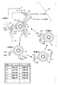
- FIG. 1 is a diagram illustrating a configuration of a removal object removing device according to an embodiment of the present invention, turning of each holding portion and each scraper around a swivel shaft portion.
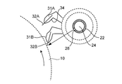
- FIG. 2 is a vertical cross-sectional view when one scraper is in the standby position.
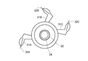
- FIG. 3 is a schematic side view showing another example (1) of the scraper device.
- FIG. 4 is a diagram showing another example (2) of the scraper device.
- FIG. 5 is a diagram showing another example (3) of the scraper device.
- FIG. 6 is a prior art scraper device.
- FIG. 1 shows a rotating device 20 having a function of removing an object to be removed according to an embodiment of the present invention.
- the rotating device 20 has an object removal function for removing deposits and surpluses, and is an embodiment of a holding mechanism that movably holds a scraper described later.
- the rotating device 20 is located on the left side of the rotating device 20 and can rotate around the rotating shaft in the state (A) of the states (A) to (D) showing a series of operation states described in detail below. It is used to remove deposits and surpluses adhering to the outer peripheral surface of the cylindrical body 10 (hereinafter, these deposits and surpluses are collectively referred to as “objects to be removed”).
- the rotating device 20 having a function of removing an object to be removed includes a swivel shaft portion 22 extending parallel to the rotating shaft of the columnar body, and two scrapers 31A extending along the longitudinal direction (axial direction) of the swivel shaft portion 22. It is equipped with 31B. Both ends of the swivel shaft portion 22 are fixed to the end plate 21 via the shaft fixing portion 23, respectively. As shown by the broken line in the drawing, these end plates 21 are provided to attach the rotating device 20 to each of the upright columns 11 and to fix each member constituting the rotating device 20.
- the scraper 31A is the first scraper and the scraper 31B is the second scraper. Further, the scraper device is composed of the scrapers 31A and 31B and the swivel shaft portion 22.
- the scrapers 31A and 31B have the same shape as each other, and are provided with removable blades 32A and 32B, which are members that actually come into contact with the outer peripheral surface of the columnar body, respectively. That is, for example, the scrapers 31A and 31B have a main body portion having a clamp structure, and the blades 32A and 32B are sandwiched by the main body portions, respectively, and the sandwiched state in the main body portion is fixed by bolts (not shown) or the like. As a result, the scrapers 31A and 31B are configured to hold the blades 32A and 32B on the tip side (cylindrical body side).
- the blades 32A and 32B are elongated plate-shaped members extending in the rotation axis direction of the columnar body, that is, the longitudinal direction of the rotation shaft portion 22, and are, for example, elastic bodies such as plastic and rubber, in this example PET (polyethylene terephthalate). It is composed of blades. As shown in the state (A) of FIG. 1, these blades 32A and 32B are attached to the scrapers 31A and 31B so as to lie down toward the downstream side in the rotation direction of the columnar body 10, that is, so as to have a reverse angle. ing. Therefore, of both sides of the blades 32A and 32B in the longitudinal direction, the surface facing the swivel shaft portion 22 is the surface on the surface of the columnar body 10 that scrapes the object to be removed.
- the scrapers 31A and 31B cannot overtake each other, but can independently turn around the turning shaft portion 22.
- the scrapers 31A and 31B have substantially the same length in the longitudinal direction of the swivel shaft portion 22, and are configured to overlap each other when they come into contact with each other as they swivel around the swivel shaft portion 22.
- the turning radii of the scrapers 31A and 31B that is, the radii of the outer circumference of the area through which the scraper swivels around the swivel shaft portion 22, are mutual except for the difference in wear of the blades 32A and 32B. It is the same.
- the scraper 31A is held by a holding portion 33 attached to the swivel shaft portion 22 so as to be swivel around the swivel shaft portion 22.
- the holding portion 33 has a base end portion that is rotatably attached to the swivel shaft portion 22 around the swivel shaft portion 22, and an arm portion that extends from the base end portion and holds the scraper 31A. They are arranged so as to be separated from each other along the longitudinal direction of the swivel shaft portion 22.
- a plurality of holding portions 33 are provided along the longitudinal direction of the swivel shaft portion 22.
- the holding portions 33 are mechanically connected to each other via the scraper 31A, if the holding portion 33 is swiveled together with the scraper 31A around the swivel shaft portion 22 and one of the holding portions 33 is swiveled, the holding portion 33 is held. The rest of the part 33 and the scraper 31A will also turn at the same time.
- the scraper 31B has a holding portion 33, each of which has a base end portion that is rotatably attached to the swivel shaft portion 22 around the swivel shaft portion 22 and an arm portion that extends from the base end portion and holds the scraper 31B.
- the holding portions 33 are mechanically connected to each other via the scraper 31B.
- the holding portion 33 the one for the scraper 31A and the one for the scraper 31B are alternately arranged by repeating one or more. That is, the holding portion for holding the scraper 31A and the holding portion for holding the scraper 31B are alternately arranged along the longitudinal direction of the swivel shaft portion 22.
- the total number of holding portions for holding the scraper 31A may be one, but is preferably plural.
- the total number of holding portions for holding the scraper 31B may be one, but is preferably plural.
- the holding portion 33 can turn in the same direction as the rotation direction of the columnar body, it is preferable that the holding portion 33 does not turn in the direction opposite to the rotation direction of the columnar body, and prevents the holding portion 33 from turning in the opposite direction. Therefore, for example, it is preferable that a one-way bearing is provided inside the holding portion 33.
- the swivel shaft portion 22 it is preferable to use a member that is tubular and has a gas flow region formed inside.
- a member that is tubular and has a gas flow region formed inside.
- at least one end of the swivel shaft portion 22 is used as a supply hole (not shown) for supplying a gas such as air to the inside of the gas flow region, and the swivel shaft portion 22
- a ejection hole 28 for blowing gas from the gas flow region to the outside of the swirl shaft portion 22 is formed.
- the supply hole communicates with the tubular gas introduction portion 24 provided in the shaft fixing portion 23. By supplying the gas from the outside through the gas introduction unit 24, the gas is blown out from the ejection hole 28 through the gas flow region.
- the ejection hole 28 is formed at the central portion of the swivel shaft portion 22 in the longitudinal direction.
- the swivel shaft portion 22, the two scrapers 31A and 31B, and the holding portion 33 constitute a scraper device which is a basic element constituting the rotating device 20 having a function of removing an object to be removed. ..
- the scrapers 31A and 31B can rotate independently, that is, around the rotating shaft portion 22 while changing the distance between them. Therefore, utilizing this, the columnar body 10 can be rotated.
- one scraper 31A (31B) is in contact with the outer peripheral surface of the columnar body 10 without substantially changing the position where the scraper contacts on the outer peripheral surface, and the other scraper 31B (31A) is in contact with the outer peripheral surface. ) Can be instantly switched to the state of contact.
- the blades 32A and 32B can be replaced without stopping the rotation of the columnar body 10 and without adversely affecting the quality of the product or the like.
- FIG. 1 is a diagram schematically illustrating the removal of the object to be removed from the outer peripheral surface of the columnar body 10 by the rotating device 20 having the function of removing the object to be removed, and shows the movements of the scrapers 31A and 31B. .. Five positions, a processing position, a stop position, a replacement position, a standby position, and a contact position, are defined for each of the scrapers 31A and 31B according to the turning angle around the turning shaft portion 22.
- the columnar body 10 is assumed to rotate counterclockwise as shown by an arrow in the figure.
- the state (A) in FIG. 1 shows a state in which the scraper 31A is in the processing position and the scraper 31B is in the contact position.
- the processing position is a position where one of the two scrapers 31A and 31B, the scraper 31A (31B), comes into contact with the outer peripheral surface of the columnar body 10 to remove the object to be removed.
- the contact position is a position through which the scraper 31A (31B) passes as the scraper 31A (31B) turns.
- the tip of the scraper 31B (the tip of the blade 32B) is slightly away from the outer peripheral surface of the columnar body 10 at the contact position, but the operator further lowers the scraper 31B.
- the scraper 31A By manually turning toward the scraper 31A, the scraper 31B starts to move toward the processing position.
- the scraper 31A that was previously in the processing position is pushed downward from the processing position by the scraper 31B by turning the scraper 31B to the processing position.
- both the scrapers 31A and 31B are formed because the blades 32A and 32B are made of elastic bodies.
- the blades 32A and 32B come into contact with the outer peripheral surface of the columnar body 10 at the same time for a moment. Then, the outer peripheral surface of the columnar body 10 between the blades 32A and 32B advances toward the upper blade 32B, and the object to be removed adhering to the outer peripheral surface is scraped off by the blade 32B. This prevents the outer peripheral surface of the columnar body 10 from forming a region that is not scraped off by the scrapers 31A and 31B. Further, both scrapers 31A and 31B come into contact with the outer peripheral surface of the columnar body 10 at the same time for a moment, and the scraping position by the scrapers 31A and 31B on the outer peripheral surface of the columnar body 10 does not substantially change.
- the rotating device 20 having the function of removing the object to be removed according to the present embodiment, such an influence on the product can be eliminated.
- the scraper 31A extruded from the processing position turns to the lower position in the figure by gravity and stops at the stop position.
- the scraper 31A is in the stop position and the scraper 31B is in the processing position.
- gas such as air is blown out from the swivel shaft portion 22 with respect to the scraping surface of the object to be removed in the scraper 31B.
- the stop position is set at a position where the scraper 31A does not interfere with the blowing of gas.
- a position that is substantially opposite to the processing position with the swivel shaft portion 22 in between is set as a replacement position for replacing the scraper 31B.
- the blade 32B can be replaced with respect to the scraper 31B at the replacement position.
- the scraper 31A is in the replacement position and the scraper 31B is still in the processing position.
- the scraper 31A is turned to the standby position.
- the standby position is a position before advancing to the contact position and is a position separated above the contact position.
- the scraper 31A is in the standby position, and the scraper 31B is still in the processing position.
- the scraper 31A comes into contact with the scraper 31B at the processing position and then moves to the processing position. That is, the state (D) in FIG. 1 returns to the state (A), but in that case, the scraper 31A and the scraper 31B are exchanged with the previous state (A) (this is the state (A)). Call it')).
- the drawing of the columnar body 10 is omitted from the state (B) to the state (D) of FIG.
- the removal target object adhering to the outer peripheral surface of the columnar body 10 is removed by one of the scrapers 31A (31B) of the scrapers 31A and 31B.
- the other scraper 31B (31A) can be replaced.
- the blades 32A and 32B of the scrapers 31A and 31B come into contact with the outer peripheral surface of the columnar body 10 in a reverse angle form with respect to the rotation direction of the columnar body 10. That is, when the scrapers 31A and 31B come into contact with the outer peripheral surface of the columnar body 10, they take a posture of inclining so as to approach the outer peripheral surface of the columnar body 10 toward the upstream side in the rotation direction of the columnar body 10. ..
- the reverse angle form it is possible to achieve reliable scraping performance at a lower contact pressure.
- the angle ⁇ formed by the tangent line of the outer peripheral surface is preferably 60 ° or less on the acute angle side. Further, more preferably, the range of 15 ° or more and 45 ° or less on the acute angle side is preferable.
- FIG. 2 is a cross-sectional view when the scraper 31A is in the standby position and the scraper 31B is in the processing position.
- a hollow one that is, a pipe is used as the swivel shaft portion 22, and the inside of the pipe is a gas flow region.
- An ejection hole 28 that communicates with the gas flow region and blows out the gas in the gas flow region is provided on the outer peripheral surface of the swivel shaft portion 22.
- the ejection holes 28 direct the gas as shown by the straight arrow in the drawing toward the contact line due to the contact of the blades 32A and 32B with the outer peripheral surface of the columnar body 10 when the scrapers 31A and 31B are in the processing position. It is formed to blow out.
- the blown gas blows off the object to be removed scraped from the outer peripheral surface of the columnar body 10 by the blades 32A and 32B from the blades 32A and 32B on the spot. As a result, a stable scraping effect can be continuously obtained.
- the scrapers 31A and 31B each have a curved cross section in terms of a plane perpendicular to the longitudinal direction of the swivel shaft portion 22 (that is, the rotation axis direction of the columnar body 10).
- the surface facing the inside of the curve is called the inner surface
- the surface facing the outside of the curve is called the back surface.
- the cross-sectional shapes of the scrapers 31A and 31B are defined so that the back surface of the scraper 31A and 31B can be inserted. Further, a receiving portion 34 is provided on the inner surface of each of the scrapers 31A and 31B so that when the back surface of the other scraper 31B (31A) enters the inner surface of one scraper 31A (31B), the back surface can be received. It is formed.
- the scrapers 31A and 31B at the processing position vibrate or move when the object to be removed is removed from the outer peripheral surface of the rotating columnar body 10. It is necessary not to do so, and it is necessary to securely fix the scrapers 31A and 31B at the processing position. It is necessary to fix the scrapers 31A and 31B at the replacement position and the standby position. It is preferable that the scrapers 31A and 31B can be fixed at the stop position as well. On the other hand, it is also necessary for the operator to be able to swivel the scrapers 31A and 31B around the swivel shaft portion 22.
- a recess 44 is formed on the outer peripheral surface of the base end portion of the holding portion 33 described above.
- a plunger 43 mechanically fixed to the shaft fixing portion 23 is provided as a locking portion, and the plunger 43 engages with the recess 44 of the holding portion 33 in a protruding state.
- the structure is such that the holding portion 33 can be projected and retracted freely.
- the holding portion 33 When the tip of the plunger 43 protrudes, the holding portion 33 is fixed by the plunger 43, and when the tip of the plunger 43 is pulled in, the holding portion 33 can swivel around the swivel shaft portion 22.
- FIG. 1 of the plunger 43 that can be engaged with the recess 44 of the holding portion 33 connected to the scraper 31A, the plunger 43 on the front side of the paper surface is shown, but the back side (back side of the paper surface) of the swivel shaft portion 22 is shown.
- a holding portion 33 connected to the scraper 31B is provided, and a plunger 43 that can be engaged with the recess 44 of the holding portion 33 is provided.
- the recess 44 is a holding portion so that the recess 44 faces the tip of the plunger 43 when the scraper 31A is in each of the processing position, the stop position, the replacement position and the standby position. It is provided at four locations on the outer peripheral surface of the base end portion of 33. Similarly, in the holding portion 33 connected to the scraper 31B, the recesses 44 are formed at four locations on the outer peripheral surface of the base end portion. In order to avoid interference with the scrapers 31A and 31B while arranging the plunger 43 close to the holding portion 33, the recess 44 is provided on the outer peripheral surface of the base end portion of the holding portion 33 outside the turning region of the scrapers 31 and 31B.
- the swivel shaft portion 22 is formed on both end sides.
- the scrapers 31A and 31B are placed at the processing position, the stop position, the replacement position, and the standby position, respectively. It can be stopped.
- the tip of the plunger 43 is formed.
- the scraper 31A (31B) can be swiveled by shrinking the portion away from the swivel shaft portion 22 side and overcoming the edge of the recess 44 to reach the outer peripheral surface of the base end portion of the holding portion 33.
- the scrapers 31A and 31B can be fixed in a predetermined position by the plunger 43 and the recess 44 on the outer peripheral surface of the base end portion of the holding portion 33. Further, it is provided with a mechanism for an operator to rotate the scrapers 31A and 31B and more reliably fix the scrapers 31A and 31B to the processing position.
- One scraper 31A is connected to and supported by the holding portion 33, of which the outer peripheral surface of the base end portion of the holding portion 33 and the outer peripheral surface of the holding portion 33 located farthest from the holding portion 33.
- a recess 42 into which one end of the rod-shaped body 41 for turning the scraper 31A can be inserted is formed in at least one of the two.
- At least one of the outer peripheral surface of the base end portion of the holding portion 33 connected to the other scraper 31B and the outer peripheral surface of the holding portion 33 connected to the scraper 31B located farthest from the holding portion 33 are formed with recesses 42 into which one end of a rod-shaped body 41 for turning the scraper 31B can be inserted.
- the operator inserts one end of the rod-shaped body 41 into the recess 42 and then moves the other end of the rod-shaped body 41 in the turning direction of the scraper 31A (31B) to pull in the tip of the plunger 43 and pull the plunger.
- the fixing of the base end portion of the holding portion 33 by 43 can be released, and the scrapers 31A and 31B can be swiveled.
- a round bar-shaped stopper 25 is provided at a position extending along the longitudinal direction of the swivel shaft portion 22 and at a position separated upward from the swivel shaft portion 22.
- the stopper 25 has a stopper on the front end side side surface of the rod-shaped body 41 when the scrapers 31A and 31B are in the processing position. It is provided at a height position so as to come into contact with the side surface of the 25. Both ends of the stopper 25 are rotatably attached to the end plate 21 so that the stopper 25 can rotate around an axis extending along the longitudinal direction of the stopper 25.
- the holding portion 33 is configured to rotate in only one direction by a one-way bearing or the like, and for this reason, the rod-shaped body 41 is strongly pressed by the stopper 25, and it becomes difficult to pull out the rod-shaped body 41 from the recess 42.
- the portion of the outer peripheral surface of the stopper 25 that the rod-shaped body 41 comes into contact with in order to stop the rotation of the scrapers 31A and 31B is referred to as a contact portion.
- a notch portion 45 is formed on the outer peripheral surface of the stopper 25 at a position separated from the contact portion in the circumferential direction of the stopper 25.
- the rod-shaped body 41 that has been in contact with the stopper 25 at the contact portion of the stopper 25 has a notch 45. Therefore, it will not come into contact with the stopper 25. Since the rod-shaped body 41 is not pressed from the side surface side in a state where it does not come into contact with the stopper 25 due to the notch portion 45, it can be easily removed from the recess 42.
- the stopper 25 is rotated and the rod-shaped body 41 corresponding to the scraper 31A is pulled out.
- the rod-shaped body 41 corresponding to the scraper 31B may be swiveled so that the scraper 31B is once swiveled to the contact position and then moved to the processing position.
- the scraper 31A is pushed out from the processing position by the scraper 31B and turns to the stop position.
- a method for manufacturing a microporous membrane using the rotating device 20 having the above-mentioned removal target removal function will be described.
- a diluent such as liquid paraffin is added to the polyolefin resin, and these are melt-kneaded by a twin-screw extruder or the like to obtain a resin solution.
- the resin solution is extruded into a film on the outer peripheral surface of the cooling roll, which is the columnar body 10, using a base such as a T-shaped die.
- the cooling roll is a columnar body 10, and the rotating device 20 of the present embodiment removes objects to be removed such as a diluent remaining on the surface of the cooling roll.
- the resin solution is cooled and a sheet-shaped molded product is obtained.
- a rotating device 20 having a function of removing objects to be removed while rotating the cooling roll removes objects to be removed such as a diluent from the outer peripheral surface of the cooling roll, and is continuous with respect to the outer peripheral surface from which the objects to be removed of the cooling roll are removed.
- a sheet-shaped molded product can be continuously obtained as a long film.
- the sheet-shaped molded product is stretched in the mechanical direction (MD) and the width direction (TD), and then the diluent is dissolved and removed from the sheet-shaped molded product using a cleaning solvent or the like to obtain a film of a polyolefin microporous film. can get.
- the raw material resin is extruded from the mouthpiece to the surface of the columnar body 10 and cooled to form a resin sheet. Therefore, since the low molecular weight component contained in the raw material resin adheres to the surface of the columnar body 10 as a removal target, the removal target is removed by the rotating device 20 having the removal target removal function of the present invention. .. Then, the cooled resin sheet is stretched to obtain a film.
- the first scraper 31A and the second scraper 31B can turn around the turning shaft portion 22 while changing the distance between them.
- the positions where the scrapers 31A and 31B come into contact with each other on the outer peripheral surface of the columnar body 10 are not substantially changed, and the scrapers 31A and 31B are further attached to the columnar body 10. From a state in which one scraper 31A (31B) is in contact with the outer peripheral surface of the columnar body 10 to a state in which the other scraper 31B (31A) is in contact with the outer peripheral surface of the columnar body 10 without intervening a time during which one of them is not in contact.
- the shapes of the scrapers 31A and 31B are configured so as to overlap each other. ing. Specifically, the back surface of the other scraper 31B (31A) enters the inner surface of one scraper 31A (31B), and the back surface of the other scraper 31B (31A) is received by the inner surface of the one scraper 31A (31B). There is a part. Therefore, although the scrapers 31A and 31B are configured to be in contact with each other and can be switched quickly, damage to the scrapers 31A (31B) due to the contact can be suppressed.
- the configuration 33 that rotatably holds the scraper 31A on the swivel shaft portion 22 and the configuration 33 that rotatably holds the scraper 31B on the swivel shaft portion 22 are arranged alternately along the longitudinal direction of the swivel shaft portion 22. It is arranged. Therefore, the stresses applied to the scrapers 31A and 31B are substantially equal, and the distribution of the stresses in the longitudinal direction of the swivel shaft portion 22 is also substantially equal. Therefore, for example, even if one scraper 31A leaves the object to be removed scraped off on the cooling roll, the other scraper 31B will be in the same state. Therefore, even if the scrapers 31A and 31B are replaced, the change in the surface state on the cooling roll is suppressed, so that the influence of the replacement on the film is minimized or has no effect.
- the object to be removed may be completely scraped.
- the magnitude of the contact pressure of the scrapers 31A and 31B with respect to the cooling roll may be determined.
- the object to be removed may be scraped off with scrapers 31A and 31B, leaving a very small amount of residue.
- the resin solution cooled on the cooling roll proceeds to the subsequent steps with the removal target involved. Therefore, in the film to be a product, parameters in various processes are adjusted so that the physical properties of the film to be removed are within the standard values in the state where the object to be removed is taken in.
- the amount of the object to be removed scraped by the scrapers 31A and 31B in the cooling roll decreases or increases. If this happens, the physical characteristics of the film that has been adjusted after taking in the object to be removed may change, and as a result, the product may exceed the standard value. In other words, even if the object to be removed on the cooling roll is completely scraped or left behind to some extent, it is important to continue the production of the film while continuing the scraped state.
- the contact pressure applied to the cooling roll is aligned between the scrapers 31A and 31B as described above, and the stress distribution is also aligned in the longitudinal direction.
- the arrangement of the members holding the scrapers 31A and 31B is adjusted. Therefore, even if the scrapers 31A and 31B are replaced a plurality of times or a large number of times, the production can be continued while suppressing the influence on the product. Therefore, for example, even in the case of producing a long film of 3000 m or 6000 m or more, the film can be produced while being within a specific standard.
- the scrapers 31A and 31B are tilted so as to sleep toward the downstream side in the rotation direction of the cooling roll. That is, the angle formed by the blades 32A and 32B attached to the scrapers 31A and 31B and the tangent line at the point where the blades 32A and 32B come into contact with the cooling roll when viewed from the end of the swivel shaft portion 22 is 15 ° or more and 45 ° or less. It is set to be so-called "reverse angle" format. This point will be described in detail.
- the scraper 31A (31B) at the processing position is replaced and turned to the stop position, the scraper 31A (31B) needs to move upward against gravity, so such a drive system is used as an apparatus. It becomes necessary to add it, which leads to an increase in the size of the device. Therefore, the present invention realizes a simple device configuration that can be practically implemented by adopting a reverse angle method when continuously cleaning the surface of the cooling roll.
- the low molecular weight resin components contained in the plasticizer are aggregated and solidified.
- air or the like is used. It is preferable to remove it immediately by spraying.
- the scrapers 31A and 31B are independently swivelly configured, and an air blowing nozzle or the like cannot be arranged in the swivel region.
- the swivel shaft portion 22 that swivels the scrapers 31A and 31B is formed hollow to form a gas flow region, and the ejection holes 28 in the central portion of the swivel shaft portion 22 are connected to the blades 32A and 32B. Gas (air) is blown against it. Therefore, the object to be removed (the liquid plasticizer and the resin component dissolved in the plasticizer) collected by the blades 32A and 32B is quickly blown with air from a position facing the blades 32A and 32B. It is discharged to the outside of the system (on the end side of the swivel shaft portion 22), and the generation of solid foreign matter is suppressed.
- the residence time at which the object to be removed stays on the blades 32A and 32B is halved as compared with the case where the air is blown out from the end portion of the swivel shaft portion 22. Since it can be reduced, the generation of foreign matter can be suppressed from this point as well.
- a recess 44 and a plunger 43 as a locking portion are provided on the outer peripheral surface of the base end portion of the holding portion 33 corresponding to the positions where the scrapers 31A and 31B are stopped. Therefore, each process can be reliably performed at each position.
- the processing position is an important control item related to the characteristics of the film, which is a product, as described in detail. Since such reliable positioning is performed, the quality of the product can be stabilized. Can be planned.
- the operator uses a mechanism (rod-shaped body 41) for rotating the scrapers 31A and 31B to provide a function for the scrapers 31A and 31B to stop more reliably at the processing position.
- a stopper 25 for stopping the turning of the scrapers 31A and 31B by interfering with the rod-shaped body 41 that turns together with the scrapers 31A and 31B at the processing position is provided. Therefore, in addition to the mechanism including the recess 44 and the plunger 43 described above, further certainty can be ensured for stabilizing the quality of the product.
- the outer peripheral surface of the columnar body 10 can hold a coating liquid such as liquid, ink, or vehicle.
- the present invention may also be applied to a printing process in which a liquid holding member such as a mesh or a screen is formed and printing is performed on a printing object such as paper or cloth via the liquid holding member.
- the coating liquid is supplied to the liquid replenishment portion which is a part of the outer peripheral surface of the columnar body 10, and two of them are on the downstream side in the rotation direction of the columnar body 10 with respect to the liquid replenishment portion.
- scraper device has two scrapers 31A and 31B
- three or more scrapers are used by using one or more scrapers 31 in addition to these scrapers 31A and 31B. May be used to remove the object to be removed.
- FIG. 3 is a schematic side view showing another example (1) of the scraper device.
- the scraper device has three scrapers 31A, 31B, 31C. Also in this case, one scraper is held at the processing position, and the remaining two scrapers are located at, for example, the replacement position and the standby position, respectively.
- FIG. 4 is a diagram showing another example (2) of the scraper device.
- This scraper device has a cylindrical body 51 and a hollow cylindrical body 52 formed concentrically on the outer circumference of the cylindrical body 51.
- the cylindrical body 51 may be hollow.
- the scraper 31A is integrally formed with the cylindrical body 51
- the scraper 31B is integrally formed with the hollow cylindrical body 52.
- Both ends of the cylinder 51 and both ends of the hollow cylinder 52 are rotatably supported by end plates around the rotation axes of the cylinder 51 and the hollow cylinder 52. Therefore, the scraper 31A can be swiveled together with the cylindrical body 51, and the scraper 31B can be swiveled together with the hollow cylindrical body 52. Since the hollow cylindrical body 52 can rotate relative to the cylindrical body 51, both the scraper 31A and the scraper 31B can rotate relative to each other.
- the scrapers 31A and 31B are rotatably held by the swivel shaft portion 22, but the scrapers 31A and 31B may be held so as to move other than the swivel.
- the scrapers 31A and 31B are slidably held by a guide 55 configured as a holding mechanism for holding these scrapers.
- the guide 55 is installed, for example, parallel to the tangential direction of the columnar body 10 at the processing position, and the scrapers 31A and 31B move from above to the processing position.
- the guide 55 is provided with a plunger 43 for holding the scrapers 31A and 31B at the processing position.
- the guide 55 may be linear as shown in FIG. 5 or may have a curved portion. Further, the guide 55 may be configured such that the scraper returns from the lower side to the upper side via the replacement position.
- Example 1 Using the sheet manufacturing apparatus according to the above-described embodiment, a film of a microporous polyolefin resin sheet was formed for 2 weeks.
- Sheet Material As the polyolefin used as the microporous polyolefin resin sheet material, high-density polyethylene (HDPE) and a viscosity of 1000 Pa ⁇ s were used. Here, the viscosity is measured by the method specified in JIS K7117-2 under the conditions of a shear rate of 100 / s and a temperature of 200 ° C.
- HDPE high-density polyethylene
- liquid paraffin (LP) and kinematic viscosity 51 cSt (at 40 ° C. mm 2 / s) were used.
- LP liquid paraffin
- kinematic viscosity 51 cSt at 40 ° C. mm 2 / s
- the sheet material was dried, supplied to an extruder, melt-kneaded with a diluent, and then supplied to a sheet molding base. Further, the device temperature up to the base was set to 230 ° C.
- Sheet molding base A base having a slit width of 300 mm was used, and the resin solution after the melt-kneading was discharged at 70 kg / hr.
- the LP concentration in the resin solution is 70% by mass, and 49 kg / hr is LP.
- a microporous membrane was produced in the same manner as in Example 1 except that the structure of the scraper was changed.
- the specific method for manufacturing the resin sheet is as follows. (1) Scraper A scraper 46 made of silicone rubber having a hardness of 70 degrees was provided with the configuration shown in FIG. It was installed so that the angle ⁇ to be formed was 45 ° on the acute angle side. Further, the air for discharging the object to be removed was blown from one end toward the other end. (2) Results In the manufactured microporous membrane of 1800 mm in width ⁇ 2000 m in length, the average number of defects was 0.20 / piece.
- microporous membrane manufacturing apparatus was stopped three times because the average of 0.50 defects of the four most recent membrane-forming films, which was the control value, was exceeded three times within the above-mentioned film-forming period. Therefore, a production loss of 36 hours occurred as compared with Example 1.
- the present invention is a scraper device that removes an object to be removed adhering to the outer peripheral surface of a columnar body that can rotate around a rotation axis, and replaces blades without stopping the rotation of the columnar body. It has the effect of being able to do it.
- the present invention exhibiting this effect includes a scraper device used for removing deposits and surpluses adhering to the outer peripheral surface of a columnar body, a rotating device having a function of removing objects to be removed such as deposits and surpluses, and a rotating device. It is useful for a method for removing an object to be removed from the outer peripheral surface of a columnar body, a method for producing a film using the method, and a method for producing a microporous film.
Landscapes
- Engineering & Computer Science (AREA)
- Mechanical Engineering (AREA)
- Chemical & Material Sciences (AREA)
- Health & Medical Sciences (AREA)
- Thermal Sciences (AREA)
- Materials Engineering (AREA)
- Physics & Mathematics (AREA)
- Chemical Kinetics & Catalysis (AREA)
- Medicinal Chemistry (AREA)
- Polymers & Plastics (AREA)
- Organic Chemistry (AREA)
- Cleaning In General (AREA)
- Manufacture Of Porous Articles, And Recovery And Treatment Of Waste Products (AREA)
- Extrusion Moulding Of Plastics Or The Like (AREA)
- Inking, Control Or Cleaning Of Printing Machines (AREA)
Priority Applications (2)
| Application Number | Priority Date | Filing Date | Title |
|---|---|---|---|
| JP2020537805A JP7468345B2 (ja) | 2019-09-27 | 2020-04-30 | スクレーパ装置、除去対象物除去機能を有する回転装置、除去対象物除去方法、フィルムの製造方法及び微多孔膜の製造方法 |
| KR1020217008737A KR102842963B1 (ko) | 2019-09-27 | 2020-04-30 | 스크레이퍼 장치, 제거 대상물 제거 기능을 갖는 회전 장치, 제거 대상물 제거 방법, 필름의 제조 방법 및 미다공막의 제조 방법 |
Applications Claiming Priority (2)
| Application Number | Priority Date | Filing Date | Title |
|---|---|---|---|
| JP2019-177759 | 2019-09-27 | ||
| JP2019177759 | 2019-09-27 |
Publications (1)
| Publication Number | Publication Date |
|---|---|
| WO2021059574A1 true WO2021059574A1 (ja) | 2021-04-01 |
Family
ID=75166897
Family Applications (1)
| Application Number | Title | Priority Date | Filing Date |
|---|---|---|---|
| PCT/JP2020/018269 Ceased WO2021059574A1 (ja) | 2019-09-27 | 2020-04-30 | スクレーパ装置、除去対象物除去機能を有する回転装置、除去対象物除去方法、フィルムの製造方法及び微多孔膜の製造方法 |
Country Status (3)
| Country | Link |
|---|---|
| JP (1) | JP7468345B2 (https=) |
| KR (1) | KR102842963B1 (https=) |
| WO (1) | WO2021059574A1 (https=) |
Cited By (2)
| Publication number | Priority date | Publication date | Assignee | Title |
|---|---|---|---|---|
| DE102022105636A1 (de) | 2022-03-10 | 2023-09-14 | Voith Patent Gmbh | Rakeldosiervorrichtung |
| CN119458847A (zh) * | 2024-11-26 | 2025-02-18 | 扬中市福达绝缘电器有限公司 | 一种聚四氟乙烯棒的挤塑装置及其挤塑工艺 |
Citations (5)
| Publication number | Priority date | Publication date | Assignee | Title |
|---|---|---|---|---|
| JPS58126159A (ja) * | 1982-01-22 | 1983-07-27 | Komori Printing Mach Co Ltd | 枚葉グラビア輪転印刷機 |
| JPH02270555A (ja) * | 1989-02-10 | 1990-11-05 | Ward Mach Co:The | 複式インキ付け手段をもつ印刷装置 |
| JPH0615806A (ja) * | 1992-04-25 | 1994-01-25 | Koenig & Bauer Ag | インキ出しローラにドクターブレードを当接調整する方法及び該方法を実施する装置 |
| JPH0717027A (ja) * | 1993-06-23 | 1995-01-20 | Man Roland Druckmas Ag | 輪転印刷機のためのチャンバ型ドクタブレード系におけるドクタブレードを交換する方法及び装置 |
| JP2017144711A (ja) * | 2016-02-18 | 2017-08-24 | 財團法人工業技術研究院Industrial Technology Research Institute | グラビア印刷装置 |
Family Cites Families (7)
| Publication number | Priority date | Publication date | Assignee | Title |
|---|---|---|---|---|
| US5184556A (en) * | 1992-02-18 | 1993-02-09 | Paper Converting Machine Company | Printing apparatus and method |
| KR20000051024A (ko) * | 1999-01-18 | 2000-08-16 | 윤종용 | 습식 전자사진방식 인쇄기의 스퀴즈 롤러 크리닝장치 |
| JP2006044193A (ja) | 2004-08-09 | 2006-02-16 | Isowa Corp | フレキソ印刷機のドクターブレード支持装置 |
| US7708377B2 (en) * | 2008-08-29 | 2010-05-04 | Xerox Corporation | Blade engagement apparatus for image forming machines |
| KR101520308B1 (ko) * | 2008-11-07 | 2015-05-15 | 주식회사 디엠에스 | 롤 프린팅 장치 |
| CN105992691B (zh) | 2013-12-03 | 2017-12-01 | 东丽株式会社 | 叠层多孔质膜及其制造方法 |
| CN112477379A (zh) * | 2020-11-27 | 2021-03-12 | 浙江骏驰纸制品有限公司 | 一种可提高印刷清晰度印刷用胶印机 |
-
2020
- 2020-04-30 WO PCT/JP2020/018269 patent/WO2021059574A1/ja not_active Ceased
- 2020-04-30 KR KR1020217008737A patent/KR102842963B1/ko active Active
- 2020-04-30 JP JP2020537805A patent/JP7468345B2/ja active Active
Patent Citations (5)
| Publication number | Priority date | Publication date | Assignee | Title |
|---|---|---|---|---|
| JPS58126159A (ja) * | 1982-01-22 | 1983-07-27 | Komori Printing Mach Co Ltd | 枚葉グラビア輪転印刷機 |
| JPH02270555A (ja) * | 1989-02-10 | 1990-11-05 | Ward Mach Co:The | 複式インキ付け手段をもつ印刷装置 |
| JPH0615806A (ja) * | 1992-04-25 | 1994-01-25 | Koenig & Bauer Ag | インキ出しローラにドクターブレードを当接調整する方法及び該方法を実施する装置 |
| JPH0717027A (ja) * | 1993-06-23 | 1995-01-20 | Man Roland Druckmas Ag | 輪転印刷機のためのチャンバ型ドクタブレード系におけるドクタブレードを交換する方法及び装置 |
| JP2017144711A (ja) * | 2016-02-18 | 2017-08-24 | 財團法人工業技術研究院Industrial Technology Research Institute | グラビア印刷装置 |
Cited By (2)
| Publication number | Priority date | Publication date | Assignee | Title |
|---|---|---|---|---|
| DE102022105636A1 (de) | 2022-03-10 | 2023-09-14 | Voith Patent Gmbh | Rakeldosiervorrichtung |
| CN119458847A (zh) * | 2024-11-26 | 2025-02-18 | 扬中市福达绝缘电器有限公司 | 一种聚四氟乙烯棒的挤塑装置及其挤塑工艺 |
Also Published As
| Publication number | Publication date |
|---|---|
| JPWO2021059574A1 (https=) | 2021-04-01 |
| KR20220063114A (ko) | 2022-05-17 |
| KR102842963B1 (ko) | 2025-08-06 |
| JP7468345B2 (ja) | 2024-04-16 |
Similar Documents
| Publication | Publication Date | Title |
|---|---|---|
| WO2021059574A1 (ja) | スクレーパ装置、除去対象物除去機能を有する回転装置、除去対象物除去方法、フィルムの製造方法及び微多孔膜の製造方法 | |
| KR101275609B1 (ko) | 용액 캐스팅 방법 | |
| US20250121554A1 (en) | Stretching device and method for stretching a plastic film in the transport direction thereof | |
| JP4833720B2 (ja) | 塗布液の塗布方法及び装置 | |
| JP5634927B2 (ja) | フィルム裁断装置及び方法、フィルム製造方法 | |
| CN101186094B (zh) | 浇铸装置、溶液浇铸设备、和溶液浇铸方法 | |
| JP4915812B2 (ja) | 溶液製膜方法及び洗浄装置 | |
| KR101479053B1 (ko) | 캐스팅 장치, 도프 도포 방법 및 용액 캐스팅 방법 | |
| JP7234541B2 (ja) | 減圧チャンバー、キャスト冷却装置、樹脂シートの製造装置及び樹脂シートの製造方法 | |
| CN101235159A (zh) | 高熔点化合物的去除方法和装置、溶剂回收方法和溶剂回收装置 | |
| JP2008302533A (ja) | インクジェット装置用ワイピング機構のワイパーブレード | |
| JP2012006271A (ja) | 樹脂フィルムの製造装置 | |
| JP2009066983A (ja) | 溶液製膜方法及び洗浄装置 | |
| JP2012517340A (ja) | カーテン塗工装置 | |
| JP6671495B2 (ja) | 熱可塑性樹脂フィルムの製造方法 | |
| JP2009073146A (ja) | 流延ダイ、溶液製膜設備及び溶液製膜方法 | |
| JP4467525B2 (ja) | フイルム巻取装置及び巻取方法 | |
| JP4157982B2 (ja) | ポリマー溶液の濾過方法及び溶液製膜方法 | |
| JP2009029024A (ja) | 溶液製膜方法及び設備 | |
| KR20210015828A (ko) | 도공 장치 및 도공막의 제조 방법 | |
| JP2009051195A (ja) | 溶液製膜方法及び設備 | |
| JP2006247574A (ja) | 記録用シートの製造方法及び装置 | |
| JP3915111B2 (ja) | 記録用シートの製造方法及び装置 | |
| US12522703B2 (en) | Polymer film and substrate for communication | |
| JP7141683B2 (ja) | ポリアミドフィルムの製造装置および製造方法 |
Legal Events
| Date | Code | Title | Description |
|---|---|---|---|
| ENP | Entry into the national phase |
Ref document number: 2020537805 Country of ref document: JP Kind code of ref document: A |
|
| 121 | Ep: the epo has been informed by wipo that ep was designated in this application |
Ref document number: 20869416 Country of ref document: EP Kind code of ref document: A1 |
|
| NENP | Non-entry into the national phase |
Ref country code: DE |
|
| 122 | Ep: pct application non-entry in european phase |
Ref document number: 20869416 Country of ref document: EP Kind code of ref document: A1 |