WO2021057258A1 - Dispositif portable et procédé d'affichage - Google Patents
Dispositif portable et procédé d'affichage Download PDFInfo
- Publication number
- WO2021057258A1 WO2021057258A1 PCT/CN2020/106255 CN2020106255W WO2021057258A1 WO 2021057258 A1 WO2021057258 A1 WO 2021057258A1 CN 2020106255 W CN2020106255 W CN 2020106255W WO 2021057258 A1 WO2021057258 A1 WO 2021057258A1
- Authority
- WO
- WIPO (PCT)
- Prior art keywords
- sub
- component
- dial
- wearable device
- watch body
- Prior art date
Links
Images


Classifications
-
- G—PHYSICS
- G04—HOROLOGY
- G04G—ELECTRONIC TIME-PIECES
- G04G17/00—Structural details; Housings
- G04G17/02—Component assemblies
- G04G17/04—Mounting of electronic components
-
- G—PHYSICS
- G06—COMPUTING; CALCULATING OR COUNTING
- G06F—ELECTRIC DIGITAL DATA PROCESSING
- G06F1/00—Details not covered by groups G06F3/00 - G06F13/00 and G06F21/00
- G06F1/16—Constructional details or arrangements
- G06F1/1613—Constructional details or arrangements for portable computers
- G06F1/163—Wearable computers, e.g. on a belt
-
- G—PHYSICS
- G04—HOROLOGY
- G04B—MECHANICALLY-DRIVEN CLOCKS OR WATCHES; MECHANICAL PARTS OF CLOCKS OR WATCHES IN GENERAL; TIME PIECES USING THE POSITION OF THE SUN, MOON OR STARS
- G04B47/00—Time-pieces combined with other articles which do not interfere with the running or the time-keeping of the time-piece
-
- G—PHYSICS
- G04—HOROLOGY
- G04C—ELECTROMECHANICAL CLOCKS OR WATCHES
- G04C3/00—Electromechanical clocks or watches independent of other time-pieces and in which the movement is maintained by electric means
- G04C3/001—Electromechanical switches for setting or display
- G04C3/002—Position, e.g. inclination dependent switches
-
- G—PHYSICS
- G04—HOROLOGY
- G04G—ELECTRONIC TIME-PIECES
- G04G17/00—Structural details; Housings
- G04G17/02—Component assemblies
- G04G17/06—Electric connectors, e.g. conductive elastomers
-
- G—PHYSICS
- G04—HOROLOGY
- G04G—ELECTRONIC TIME-PIECES
- G04G21/00—Input or output devices integrated in time-pieces
-
- G—PHYSICS
- G04—HOROLOGY
- G04G—ELECTRONIC TIME-PIECES
- G04G9/00—Visual time or date indication means
-
- G—PHYSICS
- G06—COMPUTING; CALCULATING OR COUNTING
- G06F—ELECTRIC DIGITAL DATA PROCESSING
- G06F1/00—Details not covered by groups G06F3/00 - G06F13/00 and G06F21/00
- G06F1/16—Constructional details or arrangements
- G06F1/1613—Constructional details or arrangements for portable computers
- G06F1/1633—Constructional details or arrangements of portable computers not specific to the type of enclosures covered by groups G06F1/1615 - G06F1/1626
- G06F1/1675—Miscellaneous details related to the relative movement between the different enclosures or enclosure parts
- G06F1/1677—Miscellaneous details related to the relative movement between the different enclosures or enclosure parts for detecting open or closed state or particular intermediate positions assumed by movable parts of the enclosure, e.g. detection of display lid position with respect to main body in a laptop, detection of opening of the cover of battery compartment
-
- G—PHYSICS
- G06—COMPUTING; CALCULATING OR COUNTING
- G06F—ELECTRIC DIGITAL DATA PROCESSING
- G06F1/00—Details not covered by groups G06F3/00 - G06F13/00 and G06F21/00
- G06F1/16—Constructional details or arrangements
- G06F1/1613—Constructional details or arrangements for portable computers
- G06F1/1633—Constructional details or arrangements of portable computers not specific to the type of enclosures covered by groups G06F1/1615 - G06F1/1626
- G06F1/1684—Constructional details or arrangements related to integrated I/O peripherals not covered by groups G06F1/1635 - G06F1/1675
- G06F1/1686—Constructional details or arrangements related to integrated I/O peripherals not covered by groups G06F1/1635 - G06F1/1675 the I/O peripheral being an integrated camera
-
- G—PHYSICS
- G06—COMPUTING; CALCULATING OR COUNTING
- G06F—ELECTRIC DIGITAL DATA PROCESSING
- G06F2200/00—Indexing scheme relating to G06F1/04 - G06F1/32
- G06F2200/16—Indexing scheme relating to G06F1/16 - G06F1/18
- G06F2200/161—Indexing scheme relating to constructional details of the monitor
- G06F2200/1614—Image rotation following screen orientation, e.g. switching from landscape to portrait mode
Definitions
- a computer program product is provided.
- the computer program product is stored in a nonvolatile storage medium, and the computer program product is configured to be executed by at least one processor to implement any of the foregoing Show the steps of the method.
- FIG. 6 is a schematic cross-sectional view of the watch body of the embodiment of the present invention.
- FIG. 17 is a schematic flowchart of a display method according to another embodiment of the present invention.
- FIG. 21 is a schematic diagram of the hardware structure of a wearable device according to various embodiments of the present invention.
- 30-position detection element 31-first component; 311-first sub-component; 311a-first trigger block; 311b-first conductive sub-component; 312-second sub-component; 312a-second trigger block; 312b- 32-second component; 321-mounting body; 321a-first surface; 321b-second surface; 322-contact; 322a-first sub-contact; 322b-second sub-contact;
- the chamfer structure 232a includes a chamfered surface 232b arranged around the display screen 24.
- the camera component 21 is connected to the chamfered structure 232a and the lens faces the chamfered surface 232b, and the camera component
- the angle ⁇ between the camera direction of 21 and the normal direction of the plane where the display screen 24 is located is any value between 30° and 60°, including two end values of 30° and 60°. The above-mentioned angle setting makes it easier for the user to see the picture on the display screen 24 no matter when the camera component 21 is taking a self-portrait or shooting an outside scene.
- one of the first component 31 and the second component 32 may include a conductive element, and the other may include a contact 322.
- the first sub-component 311 includes the first sub-conductive component 311b
- the second sub-component 312 includes the second sub-conductive component 312b.
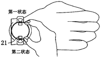
- the position detection component 30 is in the first state
- the first sub-conductive member 311b is electrically connected to the contact 322
- the second sub-conductive member 312b is electrically connected to the contact 322.
- the watch body 20 rotates 180° relative to the dial 10, and the low-level signal can be detected by the detecting foot.
- the component 21 can be used for self-portraits, and the rotation angle of the watch body 20 relative to the dial 10 can be determined by the level signal in the above-mentioned manner.
- the installation of the first sub-conductive element 311b and the second sub-conductive element 312b can be facilitated to ensure that the first sub-conductive element 311b and the reliability of the contact between the second sub-conductive member 312b and the contact 322.
- the wearable devices provided in the foregoing embodiments are all exemplified by using the first component 31 as the conductive member and the second component 32 as the contact 322. This is an optional implementation manner.
- the first sub-component 311 includes a first sub-contact 322a and a second sub-contact 322a.
- the component 312 includes a second sub-contact 322b.
- the second sub-contact 322a is electrically connected to the conductive member.
- the sub-contact 322b is electrically connected to the conductive member.
- the resistance value of the first sub-conductive member 311b and the resistance value of the second sub-conductive member 312b in the foregoing embodiments may be set to be different.
- the first conductive sub-member 311b is electrically connected to the contact 322
- the current that can be detected by the detection pin connected to the first conductive sub-member 311b or the contact 322 is the first current value.
- the contact 322 is electrically connected
- the second current value can be detected by the detection pin connected to the second sub-conductive member 312b or the contact 322, because the first sub-conductive member 311b and the second sub-conductive member 312b are The resistance is not the same, so the detected first current value and the second current value are not the same. From this, it can also be judged whether the position detecting member 30 is in the first state or the second state, and then feedback the meter body 20 relative to the dial 10 position.
- the capacitance of the first row of plate capacitors is different from that of the second parallel plate capacitor. Therefore, it is possible to determine whether the position detecting member 30 is in the first state or the second state according to the detected capacitance value, so as to satisfy The detection requirements for the rotation angle of the watch body 20 relative to the dial 10.
- the size of the notch of the mounting groove 12 is smaller than the diameter of the limiting ball 13, and the limiting ball 13 is located between the watch body 20 and the elastic member 14.
- the second side surface 233 may be provided with a rotating rail 41, and the first side surface 111 is provided with a guide 42 slidably connected to the rotating rail 41. Similarly, it may also be limited to the second side surface.
- the bottom surface 234 is provided with a rotating rail 41, and the first bottom surface 112 is provided with a guide 42 slidably connected to the rotating rail 41 on the second bottom surface 234.
- the wearable device of the foregoing embodiments further includes a watch strap 50, which is connected to the dial 10 and can be enclosed with the dial 10 to form an openable or buckle fixation. ring.
- the wearable device of the foregoing embodiments of the present invention further includes a support 60, the support 60 is disposed between the dial 10 and the watch body 20, and the support 60 is connected to the The contact area of the first bottom surface 112 is larger than the contact area of the support 60 and the second bottom surface 234.
- the support 60 can be arranged in the gap 70 and can take a variety of structural forms. It can be a cone-shaped conical structure, from the first bottom surface 112 to the second bottom surface 234, and the cross-sectional size of the support 60 Gradually decreasing, the above-mentioned structure is simple, and it is more conducive to the rotation of the watch body 20 relative to the dial 10.
- the first position information can be determined according to the structure of the position detecting element 30.
- the first position information can be a high or low level signal, of course, it can also be a current signal. If the first sub-component 311, the second sub-component 312, and the second component 32 of the position detecting element 30 are all metal plate structures, the first position information may be a capacitance signal or the like.
- step S200 may specifically include:
- step S200 further includes:
- the first position information can be determined according to the structure of the position detecting element 30.
- the first position information can be a high or low level signal, of course, it can be a current signal. If the first sub-component 311, the second sub-component 312, and the second component 32 of the position detecting element 30 are all metal plate structures, the first position signal may be a capacitance signal or the like.
- control module 400 further includes a third adjustment unit 440, configured to adjust the display parameters of the display screen 24 according to the rotation angle and/or rotation direction.
- the display parameters include brightness, contrast, resolution, and hue. And at least one of the size of the display interface.
- the accelerometer sensor can detect the magnitude of acceleration in various directions (usually three-axis), and can detect the magnitude and direction of gravity when stationary, and can be used to identify the wearable device 500 posture (such as horizontal and vertical screen switching, Related games, magnetometer attitude calibration), vibration recognition related functions (such as pedometer, tap), etc.; sensor 505 can also include fingerprint sensors, pressure sensors, iris sensors, molecular sensors, gyroscopes, barometers, hygrometers, Thermometers, infrared sensors, etc. will not be repeated here.
Landscapes
- Engineering & Computer Science (AREA)
- Physics & Mathematics (AREA)
- General Physics & Mathematics (AREA)
- Computer Hardware Design (AREA)
- Theoretical Computer Science (AREA)
- Human Computer Interaction (AREA)
- General Engineering & Computer Science (AREA)
- Electric Clocks (AREA)
Abstract
La présente invention concerne un dispositif portable et un procédé d'affichage. Le dispositif portable comprend : une plaque de cadran, la plaque de cadran étant pourvue d'une rainure de réception ; un corps de montre, au moins partiellement disposé dans la rainure de réception et relié en rotation à la plaque de cadran, le corps de montre étant pourvu d'un composant fonctionnel ; et un élément de détection de position, comprenant un premier composant et un second composant, l'un du premier composant et du second composant étant disposé sur la plaque de cadran, l'autre étant disposé sur le corps de montre, le premier composant comprenant un premier sous-composant et un second sous-composant, et le premier sous-composant et le second sous-composant étant espacés dans un sens de rotation du corps de montre ; et l'élément de détection de position présente un premier état et un second état, lorsque l'élément de détection de position est dans le premier état, le premier sous-composant est opposé au second composant, et lorsque l'élément de détection de position est dans le second état, le second sous-composant est opposé au second composant.
Priority Applications (2)
| Application Number | Priority Date | Filing Date | Title |
|---|---|---|---|
| EP20868925.7A EP4036662A4 (fr) | 2019-09-23 | 2020-07-31 | Dispositif portable et procédé d'affichage |
| US17/692,507 US11983036B2 (en) | 2019-09-23 | 2022-03-11 | Wearable device and display method |
Applications Claiming Priority (2)
| Application Number | Priority Date | Filing Date | Title |
|---|---|---|---|
| CN201910900553.5 | 2019-09-23 | ||
| CN201910900553.5A CN110716417B (zh) | 2019-09-23 | 2019-09-23 | 可穿戴设备及显示方法 |
Related Child Applications (1)
| Application Number | Title | Priority Date | Filing Date |
|---|---|---|---|
| US17/692,507 Continuation US11983036B2 (en) | 2019-09-23 | 2022-03-11 | Wearable device and display method |
Publications (1)
| Publication Number | Publication Date |
|---|---|
| WO2021057258A1 true WO2021057258A1 (fr) | 2021-04-01 |
Family
ID=69209990
Family Applications (1)
| Application Number | Title | Priority Date | Filing Date |
|---|---|---|---|
| PCT/CN2020/106255 WO2021057258A1 (fr) | 2019-09-23 | 2020-07-31 | Dispositif portable et procédé d'affichage |
Country Status (4)
| Country | Link |
|---|---|
| US (1) | US11983036B2 (fr) |
| EP (1) | EP4036662A4 (fr) |
| CN (1) | CN110716417B (fr) |
| WO (1) | WO2021057258A1 (fr) |
Families Citing this family (9)
| Publication number | Priority date | Publication date | Assignee | Title |
|---|---|---|---|---|
| CN110716417B (zh) | 2019-09-23 | 2021-01-19 | 维沃移动通信有限公司 | 可穿戴设备及显示方法 |
| CN110737190A (zh) * | 2019-09-23 | 2020-01-31 | 维沃移动通信有限公司 | 可穿戴设备及显示方法 |
| CN111352559B (zh) * | 2020-02-27 | 2021-07-13 | 维沃移动通信有限公司 | 一种电子设备及控制方法 |
| CN111338203B (zh) * | 2020-02-27 | 2021-07-23 | 维沃移动通信有限公司 | 一种电子设备及控制方法 |
| CN111586271B (zh) * | 2020-05-09 | 2022-02-18 | 维沃移动通信有限公司 | 电子设备及拍照控制方法 |
| CN111487857B (zh) * | 2020-05-30 | 2021-04-27 | 深圳市宇陀钟表科技有限公司 | 一种防水的智能手表 |
| CN112416185B (zh) * | 2020-11-19 | 2023-01-13 | 维沃移动通信有限公司 | 穿戴式设备 |
| CN112506025B (zh) * | 2020-11-24 | 2022-03-22 | 维沃移动通信有限公司 | 可穿戴设备及其拍摄方法 |
| CN113854713B (zh) * | 2021-10-28 | 2024-04-09 | 歌尔科技有限公司 | 可穿戴设备 |
Citations (7)
| Publication number | Priority date | Publication date | Assignee | Title |
|---|---|---|---|---|
| CN104280053A (zh) * | 2013-07-09 | 2015-01-14 | 莱卡地球系统公开股份有限公司 | 电容式旋转位置编码器及电容式旋转位置检测方法 |
| CN204301682U (zh) * | 2014-11-27 | 2015-04-29 | 广东欧珀移动通信有限公司 | 旋转角度检测设备及智能终端 |
| CN106060369A (zh) * | 2016-08-04 | 2016-10-26 | 广东欧珀移动通信有限公司 | 摄像头模组及终端 |
| CN205809552U (zh) * | 2016-06-21 | 2016-12-14 | 何屹 | 一种手表的360度旋转摄像头结构 |
| CN106662841A (zh) * | 2015-03-17 | 2017-05-10 | 奥米加股份有限公司 | 包括具有发光指示器的表盘的腕表 |
| CN207976717U (zh) * | 2018-01-10 | 2018-10-16 | 何屹 | 360度旋转摄像手表 |
| CN110716417A (zh) * | 2019-09-23 | 2020-01-21 | 维沃移动通信有限公司 | 可穿戴设备及显示方法 |
Family Cites Families (14)
| Publication number | Priority date | Publication date | Assignee | Title |
|---|---|---|---|---|
| CH690513A5 (de) | 1995-04-19 | 2000-09-29 | Asulab Sa | Universaluhr mit drehbarem Aussenring. |
| JP2002174688A (ja) * | 2000-12-08 | 2002-06-21 | Casio Comput Co Ltd | 電子腕時計 |
| JP4687443B2 (ja) * | 2005-12-21 | 2011-05-25 | 株式会社デンソー | ダイアル式操作装置 |
| CN201830328U (zh) * | 2009-10-21 | 2011-05-11 | 宏碁股份有限公司 | 具有通话时可锁住按键的功能的手机 |
| DE202010011758U1 (de) * | 2010-08-25 | 2010-11-25 | Abb Technology Ag | Sensoranordnung zur kontaktlosen Ermittlung der aktuellen Winkelstellung einer Welle |
| DE102010046778B4 (de) | 2010-09-28 | 2017-11-02 | Trw Automotive Electronics & Components Gmbh | Kapazitiver Drehgeber |
| CN102830385A (zh) * | 2012-09-27 | 2012-12-19 | 秦皇岛开发区海纳电测仪器有限责任公司 | 电流互感器的切换装置及其控制方法 |
| CN104808475A (zh) * | 2015-05-22 | 2015-07-29 | 广东欧珀移动通信有限公司 | 可旋转摄像的智能手表 |
| CN107682484B (zh) * | 2015-09-12 | 2019-07-30 | 赣州振南智能科技有限公司 | 一种触摸屏手机 |
| TW201733425A (zh) | 2016-03-07 | 2017-09-16 | 原相科技股份有限公司 | 具防水結構的電子裝置 |
| KR102425464B1 (ko) * | 2016-03-25 | 2022-07-27 | 삼성전자주식회사 | 회전 가능한 환형 부재를 포함하는 전자 장치 |
| TWI622899B (zh) * | 2016-09-30 | 2018-05-01 | 仁寶電腦工業股份有限公司 | 穿戴式裝置及其模組化功能組件 |
| CN206099663U (zh) * | 2016-10-11 | 2017-04-12 | 天津易哲微电子技术有限公司 | 一种使用电容编码原理检测位置的伺服电机 |
| CN207780510U (zh) * | 2017-12-12 | 2018-08-28 | 歌尔科技有限公司 | 一种旋转控制器和智能手表 |
-
2019
- 2019-09-23 CN CN201910900553.5A patent/CN110716417B/zh active Active
-
2020
- 2020-07-31 EP EP20868925.7A patent/EP4036662A4/fr active Pending
- 2020-07-31 WO PCT/CN2020/106255 patent/WO2021057258A1/fr unknown
-
2022
- 2022-03-11 US US17/692,507 patent/US11983036B2/en active Active
Patent Citations (7)
| Publication number | Priority date | Publication date | Assignee | Title |
|---|---|---|---|---|
| CN104280053A (zh) * | 2013-07-09 | 2015-01-14 | 莱卡地球系统公开股份有限公司 | 电容式旋转位置编码器及电容式旋转位置检测方法 |
| CN204301682U (zh) * | 2014-11-27 | 2015-04-29 | 广东欧珀移动通信有限公司 | 旋转角度检测设备及智能终端 |
| CN106662841A (zh) * | 2015-03-17 | 2017-05-10 | 奥米加股份有限公司 | 包括具有发光指示器的表盘的腕表 |
| CN205809552U (zh) * | 2016-06-21 | 2016-12-14 | 何屹 | 一种手表的360度旋转摄像头结构 |
| CN106060369A (zh) * | 2016-08-04 | 2016-10-26 | 广东欧珀移动通信有限公司 | 摄像头模组及终端 |
| CN207976717U (zh) * | 2018-01-10 | 2018-10-16 | 何屹 | 360度旋转摄像手表 |
| CN110716417A (zh) * | 2019-09-23 | 2020-01-21 | 维沃移动通信有限公司 | 可穿戴设备及显示方法 |
Non-Patent Citations (1)
| Title |
|---|
| See also references of EP4036662A4 * |
Also Published As
| Publication number | Publication date |
|---|---|
| EP4036662A1 (fr) | 2022-08-03 |
| US20220197334A1 (en) | 2022-06-23 |
| CN110716417B (zh) | 2021-01-19 |
| EP4036662A4 (fr) | 2022-11-09 |
| CN110716417A (zh) | 2020-01-21 |
| US11983036B2 (en) | 2024-05-14 |
Similar Documents
| Publication | Publication Date | Title |
|---|---|---|
| WO2021057258A1 (fr) | Dispositif portable et procédé d'affichage | |
| WO2021057257A1 (fr) | Dispositif pouvant être porté et procédé d'affichage | |
| CN108769304B (zh) | 电子装置 | |
| CN108683757B (zh) | 电子设备及电子装置 | |
| WO2021057260A1 (fr) | Dispositif pouvant être porté et procédé d'affichage | |
| CN108540608B (zh) | 电子装置 | |
| EP3958554B1 (fr) | Dispositif électronique comprenant une caméra escamotable et rotative | |
| JP7329150B2 (ja) | タッチボタン、制御方法及び電子機器 | |
| WO2020200005A1 (fr) | Connecteur, appareil électronique et procédé et dispositif de transmission de données | |
| CN208386625U (zh) | 电子装置 | |
| CN108769310B (zh) | 电子装置 | |
| CN208384462U (zh) | 电子装置 | |
| CN108834206B (zh) | 电子装置的控制方法及电子装置 | |
| WO2019201217A1 (fr) | Dispositif électronique | |
| CN108650346B (zh) | 电子装置 | |
| CN108111721B (zh) | 摄像头的支架组件、芯片组件、摄像头及电子设备 | |
| CN208112696U (zh) | 电子装置 | |
| CN108646384A (zh) | 一种对焦方法、装置及移动终端 | |
| CN111277741A (zh) | 摄像头装置、电子设备、光圈调节方法及提示方法 | |
| CN110086916A (zh) | 拍照方法及终端 | |
| CN110233962A (zh) | 一种置信度的优化方法、装置及计算机可读存储介质 | |
| CN110021981A (zh) | 充电器及终端 | |
| WO2019080777A1 (fr) | Ensemble lentille, caméra et dispositif électronique | |
| CN108536172A (zh) | 一种调整摄像机采集角度的方法和移动终端 | |
| WO2023207862A1 (fr) | Procédé et appareil permettant de déterminer une posture de tête |
Legal Events
| Date | Code | Title | Description |
|---|---|---|---|
| 121 | Ep: the epo has been informed by wipo that ep was designated in this application |
Ref document number: 20868925 Country of ref document: EP Kind code of ref document: A1 |
|
| NENP | Non-entry into the national phase |
Ref country code: DE |
|
| ENP | Entry into the national phase |
Ref document number: 2020868925 Country of ref document: EP Effective date: 20220425 |