WO2021053986A1 - 画像符号化装置、画像符号化方法、画像復号装置、画像復号方法、及びプログラム - Google Patents
画像符号化装置、画像符号化方法、画像復号装置、画像復号方法、及びプログラム Download PDFInfo
- Publication number
- WO2021053986A1 WO2021053986A1 PCT/JP2020/029946 JP2020029946W WO2021053986A1 WO 2021053986 A1 WO2021053986 A1 WO 2021053986A1 JP 2020029946 W JP2020029946 W JP 2020029946W WO 2021053986 A1 WO2021053986 A1 WO 2021053986A1
- Authority
- WO
- WIPO (PCT)
- Prior art keywords
- quantization parameter
- block
- image
- decoded
- quantization
- Prior art date
Links
- 238000000034 method Methods 0.000 title claims description 86
- 238000013139 quantization Methods 0.000 claims abstract description 287
- 238000006243 chemical reaction Methods 0.000 claims description 149
- 230000008569 process Effects 0.000 claims description 45
- 230000006870 function Effects 0.000 claims description 22
- 230000009466 transformation Effects 0.000 abstract description 11
- 238000012937 correction Methods 0.000 description 56
- 238000004590 computer program Methods 0.000 description 12
- 238000000926 separation method Methods 0.000 description 8
- 238000010586 diagram Methods 0.000 description 6
- 230000006835 compression Effects 0.000 description 5
- 238000007906 compression Methods 0.000 description 5
- 238000004364 calculation method Methods 0.000 description 3
- 230000000694 effects Effects 0.000 description 3
- 230000003044 adaptive effect Effects 0.000 description 2
- 230000008859 change Effects 0.000 description 2
- 239000003086 colorant Substances 0.000 description 2
- 238000012986 modification Methods 0.000 description 2
- 230000004048 modification Effects 0.000 description 2
- 230000006866 deterioration Effects 0.000 description 1
- 239000004973 liquid crystal related substance Substances 0.000 description 1
- 230000000007 visual effect Effects 0.000 description 1
Images


Classifications
-
- H—ELECTRICITY
- H04—ELECTRIC COMMUNICATION TECHNIQUE
- H04N—PICTORIAL COMMUNICATION, e.g. TELEVISION
- H04N19/00—Methods or arrangements for coding, decoding, compressing or decompressing digital video signals
- H04N19/10—Methods or arrangements for coding, decoding, compressing or decompressing digital video signals using adaptive coding
- H04N19/102—Methods or arrangements for coding, decoding, compressing or decompressing digital video signals using adaptive coding characterised by the element, parameter or selection affected or controlled by the adaptive coding
- H04N19/103—Selection of coding mode or of prediction mode
- H04N19/105—Selection of the reference unit for prediction within a chosen coding or prediction mode, e.g. adaptive choice of position and number of pixels used for prediction
-
- H—ELECTRICITY
- H04—ELECTRIC COMMUNICATION TECHNIQUE
- H04N—PICTORIAL COMMUNICATION, e.g. TELEVISION
- H04N19/00—Methods or arrangements for coding, decoding, compressing or decompressing digital video signals
- H04N19/50—Methods or arrangements for coding, decoding, compressing or decompressing digital video signals using predictive coding
- H04N19/593—Methods or arrangements for coding, decoding, compressing or decompressing digital video signals using predictive coding involving spatial prediction techniques
-
- H—ELECTRICITY
- H04—ELECTRIC COMMUNICATION TECHNIQUE
- H04N—PICTORIAL COMMUNICATION, e.g. TELEVISION
- H04N19/00—Methods or arrangements for coding, decoding, compressing or decompressing digital video signals
- H04N19/46—Embedding additional information in the video signal during the compression process
-
- H—ELECTRICITY
- H04—ELECTRIC COMMUNICATION TECHNIQUE
- H04N—PICTORIAL COMMUNICATION, e.g. TELEVISION
- H04N19/00—Methods or arrangements for coding, decoding, compressing or decompressing digital video signals
- H04N19/10—Methods or arrangements for coding, decoding, compressing or decompressing digital video signals using adaptive coding
- H04N19/102—Methods or arrangements for coding, decoding, compressing or decompressing digital video signals using adaptive coding characterised by the element, parameter or selection affected or controlled by the adaptive coding
- H04N19/119—Adaptive subdivision aspects, e.g. subdivision of a picture into rectangular or non-rectangular coding blocks
-
- H—ELECTRICITY
- H04—ELECTRIC COMMUNICATION TECHNIQUE
- H04N—PICTORIAL COMMUNICATION, e.g. TELEVISION
- H04N19/00—Methods or arrangements for coding, decoding, compressing or decompressing digital video signals
- H04N19/10—Methods or arrangements for coding, decoding, compressing or decompressing digital video signals using adaptive coding
- H04N19/102—Methods or arrangements for coding, decoding, compressing or decompressing digital video signals using adaptive coding characterised by the element, parameter or selection affected or controlled by the adaptive coding
- H04N19/12—Selection from among a plurality of transforms or standards, e.g. selection between discrete cosine transform [DCT] and sub-band transform or selection between H.263 and H.264
-
- H—ELECTRICITY
- H04—ELECTRIC COMMUNICATION TECHNIQUE
- H04N—PICTORIAL COMMUNICATION, e.g. TELEVISION
- H04N19/00—Methods or arrangements for coding, decoding, compressing or decompressing digital video signals
- H04N19/10—Methods or arrangements for coding, decoding, compressing or decompressing digital video signals using adaptive coding
- H04N19/102—Methods or arrangements for coding, decoding, compressing or decompressing digital video signals using adaptive coding characterised by the element, parameter or selection affected or controlled by the adaptive coding
- H04N19/124—Quantisation
- H04N19/126—Details of normalisation or weighting functions, e.g. normalisation matrices or variable uniform quantisers
-
- H—ELECTRICITY
- H04—ELECTRIC COMMUNICATION TECHNIQUE
- H04N—PICTORIAL COMMUNICATION, e.g. TELEVISION
- H04N19/00—Methods or arrangements for coding, decoding, compressing or decompressing digital video signals
- H04N19/10—Methods or arrangements for coding, decoding, compressing or decompressing digital video signals using adaptive coding
- H04N19/134—Methods or arrangements for coding, decoding, compressing or decompressing digital video signals using adaptive coding characterised by the element, parameter or criterion affecting or controlling the adaptive coding
- H04N19/157—Assigned coding mode, i.e. the coding mode being predefined or preselected to be further used for selection of another element or parameter
-
- H—ELECTRICITY
- H04—ELECTRIC COMMUNICATION TECHNIQUE
- H04N—PICTORIAL COMMUNICATION, e.g. TELEVISION
- H04N19/00—Methods or arrangements for coding, decoding, compressing or decompressing digital video signals
- H04N19/10—Methods or arrangements for coding, decoding, compressing or decompressing digital video signals using adaptive coding
- H04N19/169—Methods or arrangements for coding, decoding, compressing or decompressing digital video signals using adaptive coding characterised by the coding unit, i.e. the structural portion or semantic portion of the video signal being the object or the subject of the adaptive coding
- H04N19/17—Methods or arrangements for coding, decoding, compressing or decompressing digital video signals using adaptive coding characterised by the coding unit, i.e. the structural portion or semantic portion of the video signal being the object or the subject of the adaptive coding the unit being an image region, e.g. an object
- H04N19/176—Methods or arrangements for coding, decoding, compressing or decompressing digital video signals using adaptive coding characterised by the coding unit, i.e. the structural portion or semantic portion of the video signal being the object or the subject of the adaptive coding the unit being an image region, e.g. an object the region being a block, e.g. a macroblock
-
- H—ELECTRICITY
- H04—ELECTRIC COMMUNICATION TECHNIQUE
- H04N—PICTORIAL COMMUNICATION, e.g. TELEVISION
- H04N19/00—Methods or arrangements for coding, decoding, compressing or decompressing digital video signals
- H04N19/10—Methods or arrangements for coding, decoding, compressing or decompressing digital video signals using adaptive coding
- H04N19/169—Methods or arrangements for coding, decoding, compressing or decompressing digital video signals using adaptive coding characterised by the coding unit, i.e. the structural portion or semantic portion of the video signal being the object or the subject of the adaptive coding
- H04N19/186—Methods or arrangements for coding, decoding, compressing or decompressing digital video signals using adaptive coding characterised by the coding unit, i.e. the structural portion or semantic portion of the video signal being the object or the subject of the adaptive coding the unit being a colour or a chrominance component
-
- H—ELECTRICITY
- H04—ELECTRIC COMMUNICATION TECHNIQUE
- H04N—PICTORIAL COMMUNICATION, e.g. TELEVISION
- H04N19/00—Methods or arrangements for coding, decoding, compressing or decompressing digital video signals
- H04N19/60—Methods or arrangements for coding, decoding, compressing or decompressing digital video signals using transform coding
- H04N19/61—Methods or arrangements for coding, decoding, compressing or decompressing digital video signals using transform coding in combination with predictive coding
Definitions
- the present invention relates to an image coding technique.
- HEVC High Efficiency Video Coding
- VVC Very Video Coding
- Patent Document 1 Japanese Patent Application Laid-Open No. 2015-521826
- the quantization step (scaling factor) is designed to be 1. That is, when the quantization parameter is 4, the value does not change before and after the quantization. In other words, if the quantization parameter is greater than 4, the quantization step will be greater than 1 and the quantized value will be smaller than the original value. On the contrary, when the quantization parameter is smaller than 4, the quantization step becomes a decimal value smaller than 1, and the value after quantization becomes larger than the original value, and as a result, there is an effect of improving the gradation.
- the present invention has been made to solve the above-mentioned problems, and provides a technique for reducing the possibility that the code amount is unnecessarily increased by adaptively correcting the quantization parameter.
- the image coding apparatus of the present invention has the following configuration. That is, in an image coding apparatus that divides an image into a plurality of blocks and encodes each divided block to generate a bit stream, the coefficients of each color component of the block to be encoded are subjected to orthogonal conversion processing. When it is determined by the first determination means for determining whether or not to use and the first determination means that the coefficients of each color component of the block to be coded are subjected to the orthogonal conversion process, the coded object is subjected to the orthogonal conversion process.
- the block to be encoded is encoded using the first quantization parameter corresponding to the coefficient of each color component of the block, and the coefficient of each color component of the block to be encoded is used by the first determination means.
- the coding means for encoding the block to be encoded is used by using the second quantization parameter obtained by correcting the first quantization parameter.
- the coding means has a predetermined determination based on the first quantization parameter and a predetermined value, and corrects the first quantization parameter according to the determination result of the predetermined determination. , The second quantization parameter is derived.
- the image decoding device of the present invention has the following configuration. That is, it is an image decoding device that decodes a bit stream generated by encoding an image, and is an image decoding device that decodes the coded data included in the bit stream and corresponding to the block to be decoded in the image. Therefore, a first determination means for determining whether the residual coefficient of each color component of the block to be decoded is subjected to the orthogonal conversion process or not, and the first determination means. When it is determined that the residual coefficient of each color component of the block to be decoded is subjected to the orthogonal conversion process, the residual of each color component of the block to be decoded is based on the information decoded from the bit stream.
- a first quantization parameter corresponding to the coefficient is derived, the block to be decoded is decoded using the first quantization parameter, and the remainder of each color component of the block to be decoded is obtained by the first determination means.
- the first quantization parameter corresponding to the block to be decoded is derived based on the information decoded from the bit stream, and the first quantization parameter is derived.
- the decoding means has a decoding means for decoding the block to be decoded by using the second quantization parameter obtained by correcting the quantization parameter, and the information decoded from the bit stream is obtained by the decoding means.
- the second quantization parameter is obtained by performing a predetermined determination based on the first quantization parameter and a predetermined value and correcting the first quantization parameter according to the determination result of the predetermined determination. Is derived.
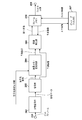
- FIG. 1 It is a block diagram which shows the structure of the image coding apparatus in Embodiment 1.
- FIG. 2 It is a block diagram which shows the structure of the image decoding apparatus in Embodiment 2.
- Reference numeral 103 denotes a quantization value correction information generation unit, which generates and outputs quantization value correction information, which is information about the correction processing of the quantization parameter that defines the quantization step.
- the method of generating the quantization value correction information is not particularly limited, but the user may input the quantization value correction information, or the image coding device may calculate from the characteristics of the input image.
- a preset value may be used as the initial value.
- the quantization parameter does not directly indicate the quantization step. For example, when the quantization parameter is 4, the quantization step (scaling factor) is designed to be 1. The larger the value of the quantization parameter, the larger the quantization step.
- the 104 is a prediction unit, which determines a method of dividing the image data in basic block units into sub-blocks. Then, the basic block is divided into subblocks having the determined shape and size. Then, intra-frame prediction, which is intra-frame prediction, inter-frame prediction, which is inter-frame prediction, and the like are performed in sub-block units to generate prediction image data. For example, the prediction unit 104 selects a prediction method to be performed for one subblock from intra-prediction, inter-prediction, and prediction coding that combines intra-prediction and inter-prediction, and performs the selected prediction. To generate predicted image data for the subblock. The prediction unit 104 also functions as a determination means for determining what kind of coding is to be performed based on a flag or the like.
- the prediction unit 104 calculates and outputs a prediction error from the input image data and the predicted image data. For example, the prediction unit 104 calculates the difference between each pixel value of the sub-block and each pixel value of the predicted image data generated by the prediction for the sub-block, and calculates it as a prediction error.
- palette flag a flag indicating that palette coding is used
- index indicating which color in the palette is used by each pixel is also output as prediction information.
- information indicating a color that does not exist in the palette (there is no corresponding entry) (hereinafter referred to as an escape value) is also output as prediction information.
- the prediction unit 104 can code a specific pixel in a subblock to be coded using palette coding using an escape value. That is, the prediction unit 104 can determine whether or not to use the escape value for each pixel. Coding with escape values is also called escape coding.
- Reference numeral 105 denotes a conversion / inverse quantization unit that performs orthogonal conversion (orthogonal conversion processing) of the prediction error in sub-block units to obtain a conversion coefficient representing each frequency component of the prediction error.
- the conversion / inverse quantization unit 105 is a conversion / quantization unit that further quantizes the conversion coefficient to obtain a residual coefficient (quantized conversion coefficient).
- Orthogonal conversion processing is not performed when conversion skip or palette coding is used.
- the function of performing orthogonal conversion and the function of performing quantization may be configured separately.
- the residual coefficient output from the conversion / quantization unit 105 is inversely quantized, the conversion coefficient is reproduced, and then inverse orthogonal conversion (inverse orthogonal conversion processing) is performed to reproduce the prediction error. It is a conversion unit. When conversion skip or palette coding is used, the inverse orthogonal conversion process is not performed. The process of reproducing (deriving) the orthogonal conversion coefficient in this way is referred to as inverse quantization.
- the function of performing inverse quantization and the function of performing inverse orthogonal conversion processing may be configured separately.
- 108 is a frame memory for storing the reproduced image data.
- the frame memory 108 is appropriately referred to to generate the prediction image data, and the reproduction image data is generated and output from the predicted image data and the input prediction error. ..
- the reproduced image is subjected to in-loop filter processing such as a deblocking filter and sample adaptive offset, and the filtered image is output.
- in-loop filter processing such as a deblocking filter and sample adaptive offset
- the residual coefficient output from the conversion / quantization unit 105 and the prediction information output from the prediction unit 104 are encoded to generate and output code data.
- the 111 is an integrated coding unit.
- the output from the quantization value correction information generation unit 103 is encoded to generate header code data. Further, a bit stream is generated and output together with the code data output from the coding unit 110.
- the information indicating the quantization parameter is also encoded in the bit stream.
- the information indicating the quantization parameter is information indicating the difference value between the quantization parameter to be encoded and another quantization parameter (for example, the quantization parameter of the previous subblock).
- the 112 is a terminal and outputs the bit stream generated by the integrated coding unit 111 to the outside.
- the moving image data is input in frame units (picture units), but a still image data for one frame may be input.
- the quantization value correction information generation unit 103 Prior to image coding, the quantization value correction information generation unit 103 generates the quantization value correction information used when correcting the quantization parameter in the subsequent stage when conversion skip or palette coding is used. ..
- the quantization value correction information generation unit 103 may generate the quantization value correction information at least when either conversion skip or palette coding is used. However, in any case, the amount of code can be further reduced by generating the quantization correction information.
- the quantization value correction information includes, for example, information indicating QPmin indicating the minimum quantization value (minimum QP value) when correcting the quantization parameter. For example, if the quantization parameter is smaller than this QPmin, it is corrected to be QPmin. A detailed explanation of how this quantization value correction information is used will be described later.
- the method of generating the quantization value correction information is not particularly limited, but the user may input (specify) the quantization value correction information, or the image coding device calculates the quantization value correction information from the characteristics of the input image.
- a predetermined initial value may be used.
- the initial value a value (for example, 4) indicating that the quantization step is 1 can be used.
- conversion skip or palette coding is used, even if the quantization step is less than 1, the image quality is the same as when the quantization step is 1, so setting QPmin to 4 uses conversion skip or palette coding. Suitable for cases.
- QPmin is used as the initial value, the quantization value correction information may be omitted. Further, as described later, when QPmin is set to a value other than the initial value, the difference value from the initial value may be used as the quantization value correction information.
- the quantization value correction information may be determined based on the implementation limitation when the prediction unit 104 determines whether or not to perform palette coding. Further, the quantization value correction information may be determined based on the implementation limitation when the conversion quantization unit 105 determines whether or not to perform orthogonal conversion.
- the generated quantization value correction information is input to the conversion / quantization unit 105, the inverse quantization / inverse conversion unit 106, and the integrated coding unit 111.
- the image data for one frame input from the terminal 101 is input to the block division unit 102.
- the block division unit 102 divides the input image data into a plurality of basic blocks, and outputs an image in basic block units to the prediction unit 104.
- the prediction unit 104 executes prediction processing on the image data input from the block division unit 102. Specifically, first, the subblock division that divides the basic block into smaller subblocks is determined.
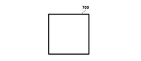
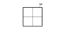
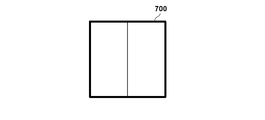
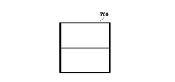
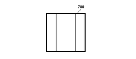
- FIGS. 7A to 7F show an example of the subblock division method.
- the 700 in the thick frame represents a basic block, and for the sake of simplicity, a 32 ⁇ 32 pixel configuration is used, and each quadrangle in the thick frame represents a subblock.
- FIG. 7B shows an example of a conventional square subblock division, in which a 32 ⁇ 32 pixel basic block is divided into 16 ⁇ 16 pixel subblocks.
- FIGS. 7C to 7F show an example of rectangular sub-block division.
- the basic block is divided into vertically long 16 ⁇ 32 pixels, and in FIG. 7D, it is divided into horizontally long rectangular sub-blocks of 32 ⁇ 16 pixels. ..
- FIGS. 7E and 7F the blocks are divided into rectangular subblocks at a ratio of 1: 2: 1. In this way, not only the square but also the rectangular sub-block is used for the coding process.
- the prediction unit 104 determines the prediction mode for each subblock to be processed (block to be encoded). Specifically, the prediction unit 104 sub-predicts intra-prediction using pixels encoded in the same frame as the frame including the sub-block to be processed, inter-prediction using pixels in different encoded frames, and the like. Determine as the prediction mode to use for each block.
- the prediction unit 104 outputs information such as subblock division and prediction mode as prediction information to the coding unit 110 and the image reproduction unit 107.
- palette coding can be selected instead of the prediction mode such as intra prediction or inter prediction.
- a palette flag indicating whether to use palette coding is output as prediction information.
- an index or escape value indicating color information included in the palette corresponding to each pixel is also output as prediction information.
- palette coding is not selected in the subblock, that is, if a prediction mode such as intra-prediction or inter-prediction is selected (for example, the value of the palette flag is 0), the palette flag is followed by other prediction information. Output the prediction error.
- a prediction mode such as intra-prediction or inter-prediction
- the conversion / quantization unit 105 performs orthogonal conversion processing and quantization processing on the prediction error output from the prediction unit 104. Specifically, first, it is determined whether or not orthogonal conversion processing is performed on the prediction error of the subblock using the prediction mode other than palette coding such as intra prediction and inter prediction.
- the prediction mode other than palette coding such as intra prediction and inter prediction.
- image coding for a natural image that is generated by capturing a landscape, a person, or the like with a camera.
- the prediction error is orthogonally converted, decomposed into frequency components, and quantized according to the human visual characteristics, so that the deterioration of image quality is not noticeable. It is possible to reduce the amount of data.
- the orthogonal conversion process is performed on the prediction error corresponding to the color component and the orthogonal conversion coefficient is calculated. Generate. Then, the quantization process using the quantization parameter is performed to generate the residual coefficient.
- the method for determining the value of the quantization parameter itself used here is not particularly limited, but the user may input the quantization parameter, or an image coding device based on the characteristics of the input image (image complexity, etc.). May be calculated. Moreover, you may use the thing specified in advance as an initial value.
- the quantization parameter QP is calculated by the quantization parameter calculation unit (not shown) and input to the conversion / quantization unit 105.
- the orthogonal conversion coefficient of the luminance component (Y) of the subblock is quantized using this quantization parameter QP, and a residual coefficient is generated.
- the orthogonal conversion coefficient of the Cb component of the subblock is quantized using the quantization parameter QPcb in which the quantization parameter QP is adjusted for the Cb component, and a residual coefficient is generated.
- the orthogonal conversion coefficient of the Cr component of the subblock is quantized using the quantization parameter QPcr adjusted for the Cr component, and a residual coefficient is generated.
- the prediction is made using the corrected quantization parameter obtained by correcting the quantization parameter QP. Quantize the error and generate the residual coefficient. Specifically, the prediction error of the luminance component (Y) of the subblock is quantized using the QP'corrected by the above-mentioned QP, and a residual coefficient is generated. On the other hand, the prediction error of the Cb component of the subblock is quantized using the QPcb'corrected by the QPcb described above, and a residual coefficient is generated. Similarly, the prediction error of the Cr component of the subblock is quantized using QPcr'corrected by the above-mentioned QPcr to generate a residual coefficient.
- the residual coefficient and conversion skip information generated in this way are input to the inverse quantization / inverse conversion unit 106 and the coding unit 110.
- the escape value itself is quantized in order to limit the increase in the code amount for the pixel for which the escape value is set.
- the corrected quantization parameters QP', QPcb', QPcr'
- QP, QPcb, QPcr the quantization parameters
- the quantized escape value is input to the inverse quantization / inverse conversion unit 106 and the coding unit 110 in the same manner as the residual coefficient.
- the inverse quantization / inverse conversion unit 106 performs inverse quantization processing and inverse orthogonal conversion processing on the input residual coefficient.
- the inverse quantization process is performed on the residual coefficient of the subblock using the prediction mode other than palette coding such as intra prediction and inter prediction, and the orthogonal conversion coefficient is reproduced.
- Whether or not orthogonal conversion is applied to each color component of each subblock is determined based on the conversion skip flag input from the conversion / quantization unit 105.
- the conversion skip flag is 0, it indicates that the conversion skip is not used.
- the quantization parameter used at this time is the same as that of the conversion / quantization unit 105, and for the residual coefficient generated by performing the orthogonal conversion process, the above-mentioned quantization parameter (for each color component) QP, QPcb, QPcr) is used.
- the conversion skip flag is 1
- the above-mentioned correction quantization parameters QP', QPcb', QPcr' ) Is used.
- the residual coefficient generated by the orthogonal conversion process is inversely quantized using the quantization parameters (QP, QPcb, QPcr), and the prediction error is reproduced by further performing the inverse orthogonal transformation. ..
- the residual coefficient generated by skipping the conversion is inversely quantized using the corrected quantization parameters (QP', QPcb', QPcr'), and the prediction error is reproduced.
- the prediction error reproduced in this way is output to the image reproduction unit 107.
- the quantized escape value is dequantized using the corrected quantization parameters (QP', QPcb', QPcr'), and the escape value is reproduced.
- the reproduced escape value is output to the image reproduction unit 107.
- the image reproduction unit 107 when the palette flag input from the prediction unit 104 indicates that the subblock is not palette-encoded, the image reproduction unit 107 appropriately refers to the frame memory 108 based on other prediction information and predicts the image. To play. Then, the image data is reproduced from the reproduced predicted image and the reproduced predicted error input from the inverse quantization / inverse conversion unit 106, input to the frame memory 108, and stored. On the other hand, when it is shown that the subblock is palette-encoded, the image data is reproduced using an index or an escape value indicating which color in the palette each pixel input as prediction information uses. Then, it is input to the frame memory 108 and stored.
- the in-loop filter unit 109 reads the reproduced image from the frame memory 108 and performs in-loop filter processing such as a deblocking filter.
- in-loop filter processing the prediction mode of the prediction unit 104, the value of the quantization parameter used by the conversion / quantization unit 105, and the non-zero value in the processing subblock after quantization (hereinafter referred to as a significance coefficient). It is performed based on whether or not there exists and the subblock division information. Then, the filtered image is input to the frame memory 108 again and stored again.
- the coding unit 110 entropy-encodes the residual coefficient generated by the conversion / quantization unit 105 and the prediction information input from the prediction unit 104 in sub-block units to generate code data. Specifically, first, a palette flag indicating whether or not the subblock is palette-coded is encoded. When the subblock is not palette-encoded, 0 is entropy-encoded as a palette flag input as prediction information, and then other prediction information and residual coefficients are entropy-encoded to generate code data. On the other hand, when the subblock is palette-encoded, 1 is entropy-encoded as a palette flag, and then an index or escape value indicating which color in the palette is used by each pixel is encoded to obtain code data. Generate. The method of entropy coding is not particularly specified, but Golomb coding, arithmetic coding, Huffman coding, etc. can be used. The generated code data is output to the integrated coding unit 111.
- the integrated coding unit 111 encodes the quantization value correction information input from the quantization value correction information generation unit 103 and generates a quantization value correction information code.
- the coding method is not particularly specified, Golomb coding, arithmetic coding, Huffman coding, or the like can be used.
- 4 indicating the quantization step 1 is used as a reference (initial value), and the difference value between the reference 4 and the minimum QP value QPmin which is the quantization value correction information is Golomb-coded. To do. Since QPmin is set to 4 in this embodiment, the 1-bit code “0” obtained by Golomb coding 0, which is the difference value from the reference 4, is used as the quantization value correction information code.
- the code amount of the quantization value correction information can be minimized.
- the table is also encoded here. Further, these codes, code data input from the coding unit 110, and the like are multiplexed to form a bit stream. Eventually, the bitstream is output from terminal 112 to the outside.
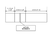
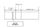
- FIG. 6A shows an example of a bit stream including the encoded quantization value correction information.
- the quantization control size information is included in any of the headers such as sequences and pictures as the quantization control size information code. In this embodiment, it is included in the header portion of the sequence as shown in FIG. 6B. However, the encoded position is not limited to this, and may be included in the header portion of the picture as shown in FIG. 6A.
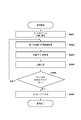
- FIG. 3 is a flowchart showing a coding process in the image coding apparatus according to the first embodiment.
- step S301 the block division unit 102 divides the input image for each frame into basic block units.
- step S302 the quantization value correction information generation unit 103 determines the quantization value correction information which is information about the correction processing of the quantization parameter.
- the quantized value correction information is encoded by the integrated coding unit 111.
- the conversion / quantization unit 105 first determines each color component (Y, Cb, Cr) of the prediction error calculated in step S303. It is determined whether or not the orthogonal conversion process is applied to the product. Then, conversion skip information is generated as the determination result. When it is determined that the orthogonal conversion process is performed on the color component, the orthogonal conversion is performed on the prediction error corresponding to the color component to generate the orthogonal conversion coefficient. Then, quantization is performed using the quantization parameters (QP, QPcb, QPcr) to generate a residual coefficient.
- the prediction error corresponding to the color component is quantized using the corrected quantization parameters (QP', QPcb', QPcr'). And generate a residual coefficient.
- the conversion / quantization unit 105 performs quantization using the corrected quantization parameters (QP', QPcb', QPcr') on the escape value, and quantizes the escape value. Generate a quantized escape value.
- step S305 the inverse quantization / inverse conversion unit 106 performs inverse quantization processing and inverse orthogonal conversion processing on the residual coefficient generated in step S304. Specifically, when a prediction mode other than palette coding is used, the inverse quantization / inverse conversion unit 106 first determines whether or not each color component of each subblock is orthogonally transformed in step S304. Judgment is made based on the conversion skip information generated in. Then, based on the determination result, the residual coefficient is subjected to inverse quantization processing.
- the quantization parameter used at this time is the same as that in step S304, and for the residual coefficient generated by performing the orthogonal conversion process, the above-mentioned quantization parameter (QP, QPcb, QPcr) is applied to each color component. ) Is used.
- the above-mentioned correction quantization parameters (QP', QPcb', QPcr') are used for each color component. That is, the residual coefficient generated by the orthogonal conversion process is inversely quantized using the quantization parameters (QP, QPcb, QPcr), and the prediction error is reproduced by further performing the inverse orthogonal transformation. ..
- the residual coefficient generated by skipping the conversion is inversely quantized using the corrected quantization parameters (QP', QPcb', QPcr'), and the prediction error is reproduced.
- the escape value quantized in step S304 is dequantized using the corrected quantization parameters (QP', QPcb', QPcr'), and the escape value is set. Reproduce.
- step S306 when the palette flag generated in step S303 indicates that the subblock is not palette-coded, the image reproduction unit 107 makes a prediction based on the prediction information generated in step S303. Play the image. Further, the image data is reproduced from the reproduced predicted image and the predicted error generated in step S305. On the other hand, when the palette flag indicates that the subblock is palette-coded, the image reproduction unit 107 uses an index or an escape value indicating which color in the palette each pixel uses in the image. Play the data.
- step S307 the coding unit 110 encodes the prediction information generated in step S303 and the residual coefficient generated in step S304 to generate code data. Specifically, first, a palette flag indicating whether or not the subblock is palette-coded is encoded. When the subblock is not palette-encoded, 0 is entropy-encoded as a palette flag input as prediction information, and then other prediction information and residual coefficients are entropy-encoded to generate code data.
- 1 is entropy-encoded as a palette flag, and then an index or escape value indicating which color in the palette is used by each pixel is encoded to obtain code data. Generate. A bit stream is generated including other code data.
- step S308 the image coding apparatus determines whether or not the coding of all the basic blocks in the frame is completed, and if so, proceeds to step S309, and if not, the next basic block. Return to step S303.
- step S309 the in-loop filter unit 109 performs in-loop filter processing on the image data reproduced in step S306, generates a filtered image, and ends the processing.
- the quantization value correction information is generated particularly in step S302, and in steps S304 and S305, the quantization parameter corrected based on the quantization value correction information is used, so that an unnecessary code amount is used. Can be prevented from increasing. As a result, the amount of data in the entire generated bit stream can be suppressed and the coding efficiency can be improved.
- the prediction error in which the conversion is skipped and the color difference residual coefficient is commonly coded may be quantized by using the corrected quantization parameter QPcbcr'.
- the quantization step is not unnecessarily reduced, the processing load can be reduced.
- the quantization parameter may be corrected when either conversion skip or palette coding is used. Even so, the possibility that the code amount is unnecessarily increased can be reduced. However, in any case, if the quantization parameter is corrected, the possibility that the code amount is unnecessarily increased can be further reduced.
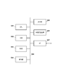
- FIG. 2 is a block diagram showing a configuration of an image decoding device according to a second embodiment of the present invention.
- decoding of the coded data generated in the first embodiment will be described as an example.
- the image decoding device basically performs the reverse operation of the image coding device of the first embodiment.
- Reference numeral 203 denotes a decoding unit, which decodes the code data output from the separation decoding unit 202 and reproduces the residual coefficient and the prediction information.
- Reference numeral 204 denotes an inverse quantization / inverse conversion unit. Similar to 106 in FIG. 1, a residual coefficient is input in subblock units, inverse quantization is performed to obtain a conversion coefficient, and inverse orthogonal transformation is performed to obtain a prediction error. Reproduce. However, when conversion skip or palette coding is used, the inverse orthogonal conversion process is not performed. Further, the function of performing inverse quantization and the function of performing inverse orthogonal transformation may be configured separately. The inverse quantization / inverse conversion unit 204 also functions as a determination means for determining what kind of coding is to be performed based on a flag or the like.
- the information indicating the quantization parameter is also decoded from the bit stream by the decoding unit 203.
- the information indicating the quantization parameter is information indicating the difference value between the target quantization parameter and another quantization parameter (for example, the quantization parameter of the previous subblock).
- the other quantization parameter may be information indicating the difference value between the average value of the plurality of quantization parameters of the plurality of other subblocks and the target quantization parameter.
- the inverse quantization / inverse conversion unit 204 derives the target quantization parameter by, for example, adding this difference value to another quantization parameter.
- the quantization parameter may be derived by adding the difference value to the separately decoded initial value. By correcting the quantization parameter derived in this way, the above-mentioned corrected quantization parameter can be derived.
- the frame memory 206 is appropriately referred to to generate the prediction image data.
- a prediction method such as intra-prediction or inter-prediction is used as in the prediction unit 104 of the first embodiment. Further, as described above, a prediction method that combines intra-prediction and inter-prediction may be used. Further, as in the first embodiment, the prediction process is performed in sub-block units. Then, the reproduced image data is generated and output from the predicted image data and the predicted error reproduced by the inverse quantization / inverse conversion unit 204.
- the 208 is a terminal and outputs the reproduced image data to the outside.
- the reproduced image is output to, for example, an external display device or the like.
- the image decoding operation in the image decoding device will be described below.
- the bitstream generated in the first embodiment is decoded.
- the bit stream input from the terminal 201 is input to the separation / decoding unit 202.
- the decoding unit 202 separates the information related to the decoding process and the code data related to the coefficient from the bit stream, and decodes the code data. Further, the separation / decoding unit 202 decodes the code data existing in the header unit of the bit stream. Specifically, the quantization value correction information is reproduced (decoded).
- the quantization value correction information code is extracted from the sequence header of the bit stream shown in FIG. 6B and decoded. Specifically, the Golomb-coded 1-bit code "0" in the first embodiment is Golomb-coded to obtain 0, and the reference 4 is added to 0 to obtain 4, which is the quantization value correction information.
- the quantization value correction information obtained in this way is output to the inverse quantization / inverse conversion unit 204. Subsequently, the code data of the basic block unit of the picture data is reproduced, and this is also output to the decoding unit 203.
- the decoding unit 203 decodes the code data and reproduces the residual coefficient, the prediction information, and the quantization parameter.
- the reproduced residual coefficient and quantization parameter are output to the inverse quantization / inverse conversion unit 204, and the reproduced prediction information is output to the image reproduction unit 205.
- the reproduced prediction information includes information on subblock division in the basic block, palette flags, conversion skip information, and the like.
- the inverse quantization / inverse conversion unit 204 performs inverse quantization and inverse orthogonal conversion on the input residual coefficient. Specifically, first, it is determined whether or not the subblock to be decoded is palette-encoded based on the palette flag input from the decoding unit 203.
- the residual coefficient of the subblock is subjected to inverse quantization processing to reproduce the orthogonal conversion coefficient.
- the quantization parameter used for the inverse quantization processing varies depending on whether or not the residual coefficient corresponding to each color component is subjected to the orthogonal conversion processing, but whether or not the orthogonal conversion processing is performed. Determines based on the conversion skip information input from the decoding unit 203.
- the quantization parameters used for this inverse quantization processing are the same as those of the inverse quantization / inverse conversion unit 106 of the first embodiment, and for the residual coefficient generated by the orthogonal transformation processing, each color component is charged.
- the above-mentioned quantization parameters QP, QPcb, QPcr
- the above-mentioned correction quantization parameters (QP', QPcb', QPcr') are used for each color component. That is, the residual coefficient generated by the orthogonal conversion process is inversely quantized using the quantization parameters (QP, QPcb, QPcr), and further subjected to the inverse orthogonal transformation to reproduce the prediction error.
- the prediction information reproduced in this way is output to the image reproduction unit 205.
- the corrected quantization parameters (QP', QPcb', QPcr') are used for the quantized escape value input from the decoding unit 203. Dequantize and regenerate the escape value. The reproduced escape value is output to the image reproduction unit 205. The values reproduced using other than the escape values (color values included in the palette indicated by the index) in the subblock are also output to the image reproduction unit 205 together with the escape values. The predicted image is composed of the values output to the image reproduction unit 205.
- the image reproduction unit 205 when the palette flag input from the decoding unit 203 indicates that the subblock is not palette-encoded, the image reproduction unit 205 appropriately refers to the frame memory 206 based on other prediction information and predicts the image. To play.
- the image data is reproduced from the predicted image and the prediction error input from the inverse quantization / inverse conversion unit 204, input to the frame memory 206, and stored. Specifically, the image reproduction unit 205 reproduces the image data by adding the predicted image and the prediction error.
- the palette flag indicates that the subblock is palette-coded
- an index indicating which color in the palette is used by each pixel input as prediction information, a reproduced escape value, etc.
- the image data is reproduced using. Then, it is input to the frame memory 206 and stored.
- the stored image data is used as a reference when making a prediction.
- the in-loop filter unit 207 reads the reproduced image from the frame memory 206 and performs in-loop filter processing such as a deblocking filter and a sample adaptive offset, as in the case of 109 in FIG. Then, the filtered image is input to the frame memory 206 again.
- in-loop filter processing such as a deblocking filter and a sample adaptive offset
- the reproduced image stored in the frame memory 206 is finally output from the terminal 208 to the outside.
- FIG. 4 is a flowchart showing an image decoding process in the image decoding apparatus according to the second embodiment.
- step S401 the separation / decoding unit 202 separates the bitstream into information related to decoding processing and code data related to coefficients, decodes the code data of the header portion, and reproduces the quantization value correction information.
- step S402 the decoding unit 203 decodes the code data separated in step S401 and reproduces the residual coefficient, the prediction information, and the quantization parameter. More specifically, first, a palette flag indicating whether or not the subblock to be decoded is palette-coded is reproduced. When the reproduced palette flag indicates 0, that is, when the subblock is not palette-coded, other prediction information, the residual coefficient, and the conversion skip information are subsequently reproduced. On the other hand, when the reproduced palette flag indicates 1, that is, when the subblock is palette-coded, an index indicating which color in the palette each pixel uses, a quantized escape value, etc. To play.
- step S403 when the subblock to be decoded is not palette-coded, the inverse quantization / inverse conversion unit 204 first determines whether or not each color component of the subblock is orthogonally transformed. The determination is made based on the conversion skip information reproduced in S402. Then, based on the determination result, the residual coefficient is subjected to inverse quantization processing.
- the quantized escape value reproduced in step S402 is dequantized using the corrected quantization parameters (QP', QPcb', QPcr'). Play the escape value.
- step S404 when the palette flag reproduced in step S402 indicates that the subblock is not palette-coded, the image reproduction unit 205 reproduces the predicted image based on the prediction information generated in step S402. To do. Further, the image data is reproduced from the reproduced predicted image and the predicted error generated in step S403.
- the image reproduction unit 205 uses an index, an escape value, or the like indicating which color in the palette each pixel uses in the image. Play the data.
- step S405 the image decoding device determines whether or not all the basic blocks in the frame have been decoded, and if so, proceeds to step S406, otherwise the next basic block is targeted. Return to step S402.
- the bit stream in which the unnecessary increase in the code amount is suppressed is decoded. Can be done.
- the quantization parameters corresponding to each color component such as Y, Cb, and Cr are corrected, but the present invention is not limited to this.
- the conversion is skipped and the color difference residual coefficient is commonly encoded.
- the residual coefficient is inversely quantized using the corrected quantization parameter QPcbcr'calculated by the above equation (4). May be good.
- QPcbcr'calculated by the above equation (4) May be good.
- it is possible to correct the appropriate quantization parameter even for the residual coefficient that is skipped for conversion and is commonly coded for the color difference residual coefficient, and decodes the bit stream that prevents an unnecessary increase in the amount of code. can do.
- the quantization step is not unnecessarily reduced, the processing load can be reduced.
- the quantization value is uniformly corrected based on a single quantization value correction information, but the quantization is performed separately for each color component or for conversion skip and palette coding.
- the configuration may use value correction information.
- QPmin, QPminY for luminance, QPmincb for Cb, and QPmincr for Cr may be individually defined, and individual quantization value corrections may be performed according to color components. This makes it possible to correct the optimum quantization parameter according to the bit depth, especially when the bit depth differs depending on the color component.
- QPmin QPminTS for conversion skip and QPminPLT for palette coding may be individually defined, and different quantization value corrections may be performed according to each case. This makes it possible to correct the optimum quantization parameter according to each case, especially when the bit depth of the output pixel value and the bit depth used in the palette coding are different.
- FIGS. 1 and 2 Each of the processing units shown in FIGS. 1 and 2 has been described in the above embodiment as being configured by hardware. However, the processing performed by each processing unit shown in these figures may be configured by a computer program.
- FIG. 5 is a block diagram showing a configuration example of computer hardware applicable to the image coding device and the image decoding device according to each of the above embodiments.
- the CPU 501 controls the entire computer using computer programs and data stored in the RAM 502 and ROM 503, and executes each of the above-described processes as performed by the image processing device according to each of the above embodiments. That is, the CPU 501 functions as each processing unit shown in FIGS. 1 and 2. It should be noted that various hardware processors other than the CPU can also be used.
- the ROM 503 stores the setting data of this computer, the boot program, and the like.
- the operation unit 504 is composed of a keyboard, a mouse, and the like, and can be operated by a user of the computer to input various instructions to the CPU 501.
- the display unit 505 displays the processing result by the CPU 501.
- the output unit 505 is composed of, for example, a liquid crystal display.
- the external storage device 506 is a large-capacity information storage device represented by a hard disk drive device.
- the external storage device 506 stores an OS (operating system) and a computer program for realizing the functions of the respective parts shown in FIGS. 1 and 2 in the CPU 501. Further, each image data as a processing target may be stored in the external storage device 506.
- the computer programs and data stored in the external storage device 506 are appropriately loaded into the RAM 502 according to the control by the CPU 501, and are processed by the CPU 501.
- a network such as a LAN or the Internet, or other devices such as a projection device or a display device can be connected to the I / F 507, and the computer acquires and sends various information via the I / F 507. Can be done.
- Reference numeral 508 is a bus connecting the above-mentioned parts.
- the computer program code read from the storage medium is written to the memory provided in the function expansion card inserted in the computer or the function expansion unit connected to the computer. Then, based on the instruction of the code of the computer program, the function expansion card, the CPU provided in the function expansion unit, or the like performs a part or all of the actual processing to realize the above-mentioned function.
- the present invention supplies a program that realizes one or more functions of the above-described embodiment to a system or device via a network or storage medium, and one or more processors in the computer of the system or device reads and executes the program. It is also possible to realize the processing. It can also be realized by a circuit (for example, ASIC) that realizes one or more functions.
- a circuit for example, ASIC
Landscapes
- Engineering & Computer Science (AREA)
- Multimedia (AREA)
- Signal Processing (AREA)
- Physics & Mathematics (AREA)
- Discrete Mathematics (AREA)
- General Physics & Mathematics (AREA)
- Compression Or Coding Systems Of Tv Signals (AREA)
- Compression, Expansion, Code Conversion, And Decoders (AREA)
Abstract
Description
以下、本発明の実施形態を、図面を用いて説明する。
QPcb’=Max(QPmin,QPcb) …(2)
QPcr’=Max(QPmin,QPcr) …(3)
(ただし、Max(A,B)はAとBの内の大きい方を表すものとする。)
例えば上式(1)~(3)において、最小QP値であるQPminが4であれば、補正量子化パラメータ(QP’、QPcb’、QPcr’)は4を下回ることがなくなる。すなわち量子化ステップが1を下回ることが無くなり、変換スキップを用いた場合に不必要な符号量の増大を防止することができる。また、Y、Cb、Crの各色成分に対して異なる最小QP値を設定する構成としてもよいが、本実施形態では同一の最小QP値QPminを全ての色成分に適用することとする。
すなわち、上記の式(4)のように、変換スキップされ色差残差係数共通符号化される予測誤差に対して、補正された量子化パラメータQPcbcr’を用いて量子化する構成としてもよい。これにより、変換スキップされ色差残差係数共通符号化される予測誤差に対しても適切な量子化パラメータの補正を行うことが可能となり、不必要な符号量の増加を防止することができる。また、不必要に量子化ステップを小さくすることもないため、処理負荷も低減することができる。
図2は、本発明の実施形態2に係る画像復号装置の構成を示すブロック図である。本実施形態では、実施形態1で生成された符号化データの復号を例にとって説明する。画像復号装置は、基本的に、実施形態1の画像符号化装置の逆の動作を行うこととなる。
図1、図2に示した各処理部はハードウェアでもって構成しているものとして上記実施形態では説明した。しかし、これらの図に示した各処理部で行う処理をコンピュータプログラムでもって構成してもよい。
各実施形態は、前述した機能を実現するコンピュータプログラムのコードを記録した記憶媒体を、システムに供給し、そのシステムがコンピュータプログラムのコードを読み出し実行することによっても達成される。この場合、記憶媒体から読み出されたコンピュータプログラムのコード自体が前述した実施形態の機能を実現し、そのコンピュータプログラムのコードを記憶した記憶媒体は本発明を構成する。また、そのプログラムのコードの指示に基づき、コンピュータ上で稼働しているオペレーティングシステム(OS)などが実際の処理の一部または全部を行い、その処理によって前述した機能が実現される場合も含まれる。
本発明は、上述の実施形態の1以上の機能を実現するプログラムを、ネットワーク又は記憶媒体を介してシステム又は装置に供給し、そのシステム又は装置のコンピュータにおける1つ以上のプロセッサーがプログラムを読出し実行する処理でも実現可能である。また、1以上の機能を実現する回路(例えば、ASIC)によっても実現可能である。
102 ブロック分割部
103 量子化値補正情報生成部
104 予測部
105 変換・量子化部
106、204 逆量子化・逆変換部
107、205 画像再生部
108、206 フレームメモリ
109、207 インループフィルタ部
110 符号化部
111 統合符号化部
202 分離復号部
203 復号部
Claims (18)
- 画像を複数のブロックに分割し、分割されたブロックごとに符号化してビットストリームを生成する画像符号化装置において、
前記符号化対象のブロックの各色成分の係数に対し、直交変換処理を施すか否かを判定する第1の判定手段と、
前記第1の判定手段によって、前記符号化対象のブロックの各色成分の係数に対し、直交変換処理を施すと判定した場合、前記符号化対象のブロックの各色成分の係数に対応する第1の量子化パラメータを用いて前記符号化対象のブロックを符号化し、
前記第1の判定手段によって、前記符号化対象のブロックの各色成分の係数に対し、直交変換処理を施さないと判定した場合、前記第1の量子化パラメータを補正することで得られる第2の量子化パラメータを用いて、前記符号化対象のブロックを符号化する符号化手段とを
有し、
前記符号化手段は、前記第1の量子化パラメータと所定の値に基づく所定の判定を行い、当該所定の判定の判定結果に応じて前記第1の量子化パラメータを補正することで、前記第2の量子化パラメータを導出する
ことを特徴とする画像符号化装置。 - 前記所定の値は、量子化パラメータの最小値を規定する値であり、前記所定の値に基づく所定の判定は、前記量子化パラメータの最小値と前記第1の量子化パラメータのうち、どちらが大きいかを判定することである
ことを特徴とする請求項1に記載の画像符号化装置。 - 前記符号化手段は前記所定の値を示す情報を符号化する
ことを特徴とする請求項1に記載の画像符号化装置。 - 前記符号化対象のブロックの色成分はCb及びCrを含む
ことを特徴とする請求項1に記載の画像符号化装置。 - 画像を符号化して生成されたビットストリームを復号する画像復号装置であって、当該ビットストリームに含まれる、前記画像内の復号対象のブロックに対応する符号化データを復号する画像復号装置であって、
前記復号対象のブロックの各色成分の残差係数が直交変換処理を施されているか、直交変換処理を施されていないかを判定する第1の判定手段と、
前記第1の判定手段によって前記復号対象のブロックの各色成分の残差係数が直交変換処理を施されていると判定された場合、前記ビットストリームから復号される情報に基づいて前記復号対象のブロックの各色成分の残差係数に対応する第1の量子化パラメータを導出し、その第1の量子化パラメータを用いて前記復号対象のブロックを復号し、
前記第1の判定手段によって前記復号対象のブロックの各色成分の残差係数が直交変換処理を施されていないと判定された場合、前記ビットストリームから復号される情報に基づいて前記復号対象のブロックに対応する第1の量子化パラメータを導出し、その第1の量子化パラメータを補正することで得られる第2の量子化パラメータを用いて、前記復号対象のブロックを復号する復号手段と
を有し、
前記ビットストリームから復号される前記情報は、
前記復号手段は、前記第1の量子化パラメータと所定の値に基づく所定の判定を行い、当該所定の判定の判定結果に応じて前記第1の量子化パラメータを補正することで、前記第2の量子化パラメータを導出する
ことを特徴とする画像復号装置。 - 前記所定の値は、量子化パラメータの最小値を規定する値であり、前記所定の値に基づく所定の判定は、前記量子化パラメータの最小値と前記第1の量子化パラメータのうち、どちらが大きいかを判定することである
ことを特徴とする請求項5に記載の画像復号装置。 - 前記復号手段は前記所定の値を示す情報をビットストリームから復号して取得する
ことを特徴とする請求項5に記載の画像復号装置。 - 前記復号対象のブロックの色成分はCb及びCrを含む
ことを特徴とする請求項5に記載の画像復号装置。 - 画像を複数のブロックに分割し、分割されたブロックごとに符号化してビットストリームを生成する画像符号化方法において、
前記符号化対象のブロックの各色成分の係数に対し、直交変換処理を施すか否かを判定する第1の判定工程と、
前記第1の判定工程によって、前記符号化対象のブロックの各色成分の係数に対し、直交変換処理を施すと判定した場合、前記符号化対象のブロックの各色成分の係数に対応する第1の量子化パラメータを用いて前記符号化対象のブロックを符号化し、
前記第1の判定工程によって、前記符号化対象のブロックの各色成分の係数に対し、直交変換処理を施さないと判定した場合、前記第1の量子化パラメータを補正することで得られる第2の量子化パラメータを用いて、前記符号化対象のブロックを符号化する符号化工程とを
有し、
前記符号化工程は、前記第1の量子化パラメータと所定の値に基づく所定の判定を行い、当該所定の判定の判定結果に応じて前記第1の量子化パラメータを補正することで、前記第2の量子化パラメータを導出する
ことを特徴とする画像符号化方法。 - 前記所定の値は、量子化パラメータの最小値を規定する値であり、前記所定の値に基づく所定の判定は、前記量子化パラメータの最小値と前記第1の量子化パラメータのうち、どちらが大きいかを判定することである
ことを特徴とする請求項9に記載の画像符号化方法。 - 前記符号化工程は前記所定の値を示す情報を符号化する
ことを特徴とする請求項9に記載の画像符号化方法。 - 前記符号化対象のブロックの色成分はCb及びCrを含む
ことを特徴とする請求項9に記載の画像符号化方法。 - 画像を符号化して生成されたビットストリームを復号する画像復号方法であって、当該ビットストリームに含まれる、前記画像内の復号対象のブロックに対応する符号化データを復号する画像復号方法であって、
前記復号対象のブロックの各色成分の残差係数が直交変換処理を施されているか、直交変換処理を施されていないかを判定する第1の判定工程と、
前記第1の判定工程によって前記復号対象のブロックの各色成分の残差係数が直交変換処理を施されていると判定された場合、前記ビットストリームから復号される情報に基づいて前記復号対象のブロックの各色成分の残差係数に対応する第1の量子化パラメータを導出し、その第1の量子化パラメータを用いて前記復号対象のブロックを復号し、
前記第1の判定工程によって前記復号対象のブロックの各色成分の残差係数が直交変換処理を施されていないと判定された場合、前記ビットストリームから復号される情報に基づいて前記復号対象のブロックに対応する第1の量子化パラメータを導出し、その第1の量子化パラメータを補正することで得られる第2の量子化パラメータを用いて、前記復号対象のブロックを復号する復号工程と
を有し、
前記ビットストリームから復号される前記情報は、
前記復号工程において、前記第1の量子化パラメータと所定の値に基づく所定の判定を行い、当該所定の判定の判定結果に応じて前記第1の量子化パラメータを補正することで、前記第2の量子化パラメータを導出する
ことを特徴とする画像復号方法。 - 前記所定の値は、量子化パラメータの最小値を規定する値であり、前記所定の値に基づく所定の判定は、前記量子化パラメータの最小値と前記第1の量子化パラメータのうち、どちらが大きいかを判定することである
ことを特徴とする請求項13に記載の画像復号方法。 - 前記復号工程において、前記所定の値を示す情報をビットストリームから復号して取得する
ことを特徴とする請求項13に記載の画像復号方法。 - 前記復号対象のブロックの色成分はCb及びCrを含む
ことを特徴とする請求項13に記載の画像復号方法。 - 請求項1~4のいずれか1項に記載の画像符号化装置の各手段として、コンピュータを機能させることを特徴とするプログラム。
- 請求項5~8のいずれか1項に記載の画像復号装置の各手段として、コンピュータを機能させることを特徴とするプログラム。
Priority Applications (5)
| Application Number | Priority Date | Filing Date | Title |
|---|---|---|---|
| KR1020227011748A KR20220051022A (ko) | 2019-09-17 | 2020-08-05 | 화상 부호화 장치, 화상 부호화 방법, 화상 복호 장치, 화상 복호 방법, 및 비일시적인 컴퓨터 판독가능한 저장 매체 |
| CN202080065321.3A CN114424563A (zh) | 2019-09-17 | 2020-08-05 | 图像编码装置、图像编码方法、图像解码装置、图像解码方法和程序 |
| BR112022004800A BR112022004800A2 (pt) | 2019-09-17 | 2020-08-05 | Dispositivo de codificação de imagem, método de codificação de imagem, dispositivo de decodificação de imagem, método de decodificação de imagem, e programa |
| EP20865972.2A EP4033763A4 (en) | 2019-09-17 | 2020-08-05 | IMAGE ENCODING DEVICE, IMAGE ENCODING METHOD, IMAGE DECODING DEVICE, IMAGE DECODING METHOD, AND PROGRAM |
| US17/690,947 US20220201288A1 (en) | 2019-09-17 | 2022-03-09 | Image encoding device, image encoding method, image decoding device, image decoding method, and non-transitory computer-readable storage medium |
Applications Claiming Priority (2)
| Application Number | Priority Date | Filing Date | Title |
|---|---|---|---|
| JP2019-168858 | 2019-09-17 | ||
| JP2019168858A JP7358135B2 (ja) | 2019-09-17 | 2019-09-17 | 画像符号化装置、画像符号化方法、及びプログラム、画像復号装置、画像復号方法、及びプログラム |
Related Child Applications (1)
| Application Number | Title | Priority Date | Filing Date |
|---|---|---|---|
| US17/690,947 Continuation US20220201288A1 (en) | 2019-09-17 | 2022-03-09 | Image encoding device, image encoding method, image decoding device, image decoding method, and non-transitory computer-readable storage medium |
Publications (1)
| Publication Number | Publication Date |
|---|---|
| WO2021053986A1 true WO2021053986A1 (ja) | 2021-03-25 |
Family
ID=74876681
Family Applications (1)
| Application Number | Title | Priority Date | Filing Date |
|---|---|---|---|
| PCT/JP2020/029946 WO2021053986A1 (ja) | 2019-09-17 | 2020-08-05 | 画像符号化装置、画像符号化方法、画像復号装置、画像復号方法、及びプログラム |
Country Status (8)
| Country | Link |
|---|---|
| US (1) | US20220201288A1 (ja) |
| EP (1) | EP4033763A4 (ja) |
| JP (2) | JP7358135B2 (ja) |
| KR (1) | KR20220051022A (ja) |
| CN (1) | CN114424563A (ja) |
| BR (1) | BR112022004800A2 (ja) |
| TW (1) | TWI820346B (ja) |
| WO (1) | WO2021053986A1 (ja) |
Families Citing this family (1)
| Publication number | Priority date | Publication date | Assignee | Title |
|---|---|---|---|---|
| WO2023132697A1 (ko) * | 2022-01-07 | 2023-07-13 | 엘지전자 주식회사 | 피쳐 부호화/복호화 방법, 장치 및 비트스트림을 저장한 기록 매체 |
Citations (3)
| Publication number | Priority date | Publication date | Assignee | Title |
|---|---|---|---|---|
| JP2015521826A (ja) | 2012-06-29 | 2015-07-30 | キヤノン株式会社 | 画像を符号化または復号するための方法およびデバイス |
| WO2019003676A1 (ja) * | 2017-06-29 | 2019-01-03 | ソニー株式会社 | 画像処理装置と画像処理方法およびプログラム |
| JP2019168858A (ja) | 2018-03-22 | 2019-10-03 | 三菱自動車工業株式会社 | 駐車車両異常検出装置 |
Family Cites Families (3)
| Publication number | Priority date | Publication date | Assignee | Title |
|---|---|---|---|---|
| US20130294524A1 (en) * | 2012-05-04 | 2013-11-07 | Qualcomm Incorporated | Transform skipping and lossless coding unification |
| EP3354019A4 (en) * | 2015-09-23 | 2019-05-22 | Telefonaktiebolaget LM Ericsson (publ) | DETERMINATION OF QUANTIZATION PARAMETER VALUES |
| US11218700B2 (en) * | 2019-07-01 | 2022-01-04 | Qualcomm Incorporated | Minimum allowed quantization parameter for transform skip mode and palette mode in video coding |
-
2019
- 2019-09-17 JP JP2019168858A patent/JP7358135B2/ja active Active
-
2020
- 2020-08-05 WO PCT/JP2020/029946 patent/WO2021053986A1/ja unknown
- 2020-08-05 EP EP20865972.2A patent/EP4033763A4/en active Pending
- 2020-08-05 KR KR1020227011748A patent/KR20220051022A/ko unknown
- 2020-08-05 CN CN202080065321.3A patent/CN114424563A/zh active Pending
- 2020-08-05 BR BR112022004800A patent/BR112022004800A2/pt unknown
- 2020-08-26 TW TW109129086A patent/TWI820346B/zh active
-
2022
- 2022-03-09 US US17/690,947 patent/US20220201288A1/en active Pending
-
2023
- 2023-09-19 JP JP2023151301A patent/JP2023164601A/ja active Pending
Patent Citations (3)
| Publication number | Priority date | Publication date | Assignee | Title |
|---|---|---|---|---|
| JP2015521826A (ja) | 2012-06-29 | 2015-07-30 | キヤノン株式会社 | 画像を符号化または復号するための方法およびデバイス |
| WO2019003676A1 (ja) * | 2017-06-29 | 2019-01-03 | ソニー株式会社 | 画像処理装置と画像処理方法およびプログラム |
| JP2019168858A (ja) | 2018-03-22 | 2019-10-03 | 三菱自動車工業株式会社 | 駐車車両異常検出装置 |
Non-Patent Citations (4)
| Title |
|---|
| KARCZEWICZ (QUALCOMM) M; Y-H CHAO (QUALCOMM); WANG (QUALCOMM) H; COBAN (QUALCOMM) M: "Non-CE8: Minimum QP for Transform Skip Mode", JOINT VIDEO EXPERTS TEAM (JVET) OF ITU-T SG 16 WP 3 AND ISO/IEC JTC 1/SC 29/ WG 11, JVET-00919-V2, 15TH MEETING, July 2019 (2019-07-01), Gothenburg, SE, pages 1 - 3, XP030207655 * |
| NGUYEN (FRAUNHOFER) T; BROSS B; SCHWARZ H; MARPE D; WIEGAND (HHI) T.,: "Non-CE8: Minimum Allowed QP for Transform Skip Mode", JOINT VIDEO EXPERTS TEAM (JVET) OF ITU-T SG 16 WP 3 AND ISO/IEC JTC 1/SC 29/ WG 11, JVET-00405-V1, June 2019 (2019-06-01), pages 1 - 3, XP030219469 * |
| See also references of EP4033763A4 |
| TSUKUBA (SONY) T; IKEDA M; YAGASAKI Y; SUZUKI (SONY) T: "AHG13/Non-CE6/CE8: Chroma Transform Skip", JOINT VIDEO EXPERTS TEAM (JVET) OF ITU-T SG 16 WP 3 AND ISO/IEC JTC 1/SC 29/WG 11, JVET-N0123-V2, 14TH MEETING, March 2019 (2019-03-01), Geneva, CH, pages 1 - 6, XP030204403 * |
Also Published As
| Publication number | Publication date |
|---|---|
| TW202114411A (zh) | 2021-04-01 |
| KR20220051022A (ko) | 2022-04-25 |
| US20220201288A1 (en) | 2022-06-23 |
| EP4033763A4 (en) | 2023-10-18 |
| JP2021048457A (ja) | 2021-03-25 |
| JP2023164601A (ja) | 2023-11-10 |
| TWI820346B (zh) | 2023-11-01 |
| EP4033763A1 (en) | 2022-07-27 |
| CN114424563A (zh) | 2022-04-29 |
| BR112022004800A2 (pt) | 2022-06-21 |
| JP7358135B2 (ja) | 2023-10-10 |
Similar Documents
| Publication | Publication Date | Title |
|---|---|---|
| WO2020184229A1 (ja) | 画像符号化装置、画像符号化方法、及びプログラム | |
| JP2023164601A (ja) | 画像符号化装置、画像符号化方法、及びプログラム、画像復号装置、画像復号方法、及びプログラム | |
| JP2024015184A (ja) | 画像復号装置及び方法及びプログラム | |
| WO2021054011A1 (ja) | 画像符号化装置、画像符号化方法、及びプログラム、画像復号装置、画像復号方法、及びプログラム | |
| WO2020184227A1 (ja) | 画像復号装置、画像復号方法、及びプログラム | |
| WO2020003740A1 (ja) | 画像符号化装置及び画像復号装置及びそれらの制御方法及びプログラム | |
| JP7493310B2 (ja) | 画像復号装置及び方法及びプログラム | |
| WO2020255820A1 (ja) | 画像符号化装置及び画像復号装置及び方法及びコンピュータプログラム | |
| WO2021187023A1 (ja) | 画像符号化装置、画像符号化方法及びプログラム、画像復号装置、画像復号方法及びプログラム | |
| WO2021049277A1 (ja) | 画像符号化装置及び画像復号装置 | |
| US11849114B2 (en) | Image encoding apparatus, image decoding apparatus, control methods thereof, and non-transitory computer-readable storage medium | |
| WO2020184223A1 (ja) | 画像復号装置、画像復号方法、及びプログラム | |
| WO2021054012A1 (ja) | 画像符号化装置、画像復号装置及びそれらの制御方法及びプログラム | |
| WO2020183859A1 (ja) | 画像符号化装置、画像復号装置、画像符号化方法、画像復号方法、及びプログラム | |
| JP2021150723A (ja) | 画像符号化装置、画像符号化方法、及びプログラム、画像復号装置、画像復号方法、及びプログラム |
Legal Events
| Date | Code | Title | Description |
|---|---|---|---|
| 121 | Ep: the epo has been informed by wipo that ep was designated in this application |
Ref document number: 20865972 Country of ref document: EP Kind code of ref document: A1 |
|
| NENP | Non-entry into the national phase |
Ref country code: DE |
|
| REG | Reference to national code |
Ref country code: BR Ref legal event code: B01A Ref document number: 112022004800 Country of ref document: BR |
|
| ENP | Entry into the national phase |
Ref document number: 20227011748 Country of ref document: KR Kind code of ref document: A |
|
| ENP | Entry into the national phase |
Ref document number: 2020865972 Country of ref document: EP Effective date: 20220419 |
|
| ENP | Entry into the national phase |
Ref document number: 112022004800 Country of ref document: BR Kind code of ref document: A2 Effective date: 20220315 |