WO2021053757A1 - Chlorine injection concentration management device, chlorine injection concentration management method, and chlorine injection concentration management program - Google Patents
Chlorine injection concentration management device, chlorine injection concentration management method, and chlorine injection concentration management program Download PDFInfo
- Publication number
- WO2021053757A1 WO2021053757A1 PCT/JP2019/036573 JP2019036573W WO2021053757A1 WO 2021053757 A1 WO2021053757 A1 WO 2021053757A1 JP 2019036573 W JP2019036573 W JP 2019036573W WO 2021053757 A1 WO2021053757 A1 WO 2021053757A1
- Authority
- WO
- WIPO (PCT)
- Prior art keywords
- concentration
- chlorine
- residual chlorine
- injection
- injection rate
- Prior art date
Links
Images


Classifications
-
- C—CHEMISTRY; METALLURGY
- C02—TREATMENT OF WATER, WASTE WATER, SEWAGE, OR SLUDGE
- C02F—TREATMENT OF WATER, WASTE WATER, SEWAGE, OR SLUDGE
- C02F1/00—Treatment of water, waste water, or sewage
- C02F1/46—Treatment of water, waste water, or sewage by electrochemical methods
- C02F1/461—Treatment of water, waste water, or sewage by electrochemical methods by electrolysis
-
- C—CHEMISTRY; METALLURGY
- C02—TREATMENT OF WATER, WASTE WATER, SEWAGE, OR SLUDGE
- C02F—TREATMENT OF WATER, WASTE WATER, SEWAGE, OR SLUDGE
- C02F1/00—Treatment of water, waste water, or sewage
- C02F1/50—Treatment of water, waste water, or sewage by addition or application of a germicide or by oligodynamic treatment
-
- C—CHEMISTRY; METALLURGY
- C02—TREATMENT OF WATER, WASTE WATER, SEWAGE, OR SLUDGE
- C02F—TREATMENT OF WATER, WASTE WATER, SEWAGE, OR SLUDGE
- C02F1/00—Treatment of water, waste water, or sewage
- C02F1/72—Treatment of water, waste water, or sewage by oxidation
- C02F1/76—Treatment of water, waste water, or sewage by oxidation with halogens or compounds of halogens
Definitions
- the present invention relates to a chlorine injection concentration control device, a chlorine injection concentration control method, and a chlorine injection concentration control program. More specifically, the present invention relates to a chlorine injection concentration control device, a chlorine injection concentration control method, and a chlorine injection concentration control program used in a seawater utilization plant such as a power plant.
- seawater electrolytic chlorine sodium hypochlorite
- sessile organisms such as barnacles and mussels that adhere to the seawater system of seawater utilization plants such as thermal power plants and nuclear power plants, and biofilms. Widely implemented.
- Patent Document 1 sodium hypochlorite is produced by electrolyzing natural seawater, and an electrolytic solution containing the sodium hypochlorite is injected into the intake of seawater to prevent the adhesion of marine organisms.
- the technology used for is disclosed.
- electrolytic chlorine sodium hypochlorite
- the concentration rapidly decreases, but the rate of decay depends on the water temperature and quality, so under conditions where the water temperature and quality fluctuate daily, sessile organisms and It is very difficult to suppress the adhesion of biofilm and maintain the residual chlorine concentration (for example, 0.02 mg / L) as the environmental conservation agreement value at the outlet of the seawater utilization plant.
- the injection concentration of electrolytic chlorine is conservative, the effect of suppressing the adhesion of attached organisms and biofilms has not been sufficiently obtained.
- the concentration is adjusted while checking the residual chlorine concentration by hand analysis at the condenser inlet about once a week, but it is based on the operator's experience and has a clear basis.
- after changing the injection rate of electrolytic chlorine it takes 30 to 50 minutes depending on the capacity of the storage tank and the flow time until the change is reflected at the inlet of the condenser. Therefore, in order to match the target value of the residual chlorine concentration, it is necessary to repeat the manual analysis many times, which is complicated. This is also a factor that the injection rate of electrolytic chlorine is set conservatively, and a sufficient adhesion suppressing effect cannot be obtained.
- the present invention has been made in view of the above problems, and it is possible to adjust the residual chlorine concentration at the inlet of the condenser to a target value without requiring complicated procedures as compared with the prior art.
- An object of the present invention is to provide a chlorine injection concentration control device.
- the present invention is a chlorine injection concentration control device for a seawater utilization plant, which is installed in the seawater utilization plant after the injection rate of chlorine injected from the chlorine injection port in the seawater utilization plant and a predetermined time after the injection. Based on the data acquisition unit that acquires the set data of the residual chlorine concentration at the inlet of the water condenser, and at least two sets of the injection rate and the residual chlorine concentration, the injection rate and the residual chlorine Based on the relationship calculation unit that exponentially approximates the relationship with the concentration, the target concentration acquisition unit that acquires the target value of the residual chlorine concentration, the target value of the residual chlorine concentration, and the exponentially approximated relationship.
- the present invention relates to a chlorine injection concentration management device including a target injection rate calculation unit for calculating a target value of the injection rate.
- a residual chlorine analysis unit that continuously measures the residual chlorine concentration at the inlet of the condenser and outputs the measured value of the residual chlorine concentration to the data input unit.
- a predicted value calculation unit that calculates a predicted value of the residual chlorine concentration at the outlet installed in the seawater utilization plant based on the target value of the residual chlorine concentration and the water temperature at the outlet of the condenser. Further provision is preferred.
- the difference between the second residual chlorine analysis unit that continuously measures the residual chlorine concentration at the outlet, the residual chlorine concentration measured by the second residual chlorine analysis unit, and the predicted value is a predetermined value. It is preferable to further include an alarm unit that issues an alarm when the above value is exceeded.
- the present invention is a chlorine injection concentration control method for a seawater utilization plant, wherein the chlorine injection rate to be injected from the chlorine injection port in the seawater utilization plant and a predetermined time after the injection into the seawater utilization plant.
- the injection rate and the residual chlorine concentration are based on a data acquisition step of acquiring a set of data of the residual chlorine concentration at the inlet of the water concentrator installed and at least two sets of the injection rate and the residual chlorine concentration data.
- the target concentration acquisition step that acquires the target value of the residual chlorine concentration, the target value of the residual chlorine concentration, and the exponentially approximated relationship.
- the present invention relates to a chlorine injection concentration control method having an optimum chlorine injection rate calculation step for calculating the optimum value of the injection rate.
- the present invention is a chlorine injection concentration control program for a seawater utilization plant, in which the chlorine injection rate to be injected from the chlorine injection port in the seawater utilization plant and the chlorine injection rate to the seawater utilization plant after a predetermined time from the injection.
- the injection rate and the residual chlorine concentration are based on a data acquisition step of acquiring a set of data of the residual chlorine concentration at the inlet of the water concentrator installed and at least two sets of the injection rate and the residual chlorine concentration data.
- the target concentration acquisition step that acquires the target value of the residual chlorine concentration, the target value of the residual chlorine concentration, and the exponentially approximated relationship.
- the present invention relates to an optimum chlorine injection rate calculation step for calculating the optimum value of the injection rate, and a chlorine injection concentration control program for causing a computer to execute the step.
- the relationship between the injection rate and the residual chlorine concentration can be shown by a straight line by using a semi-logarithmic graph.
- a set of a certain injection rate and the residual chlorine concentration at the condenser inlet after a predetermined time after injecting chlorine at the injection rate, and an injection rate different from this and the injection rate The relationship between the injection rate and the residual chlorine concentration is derived based on the set of the residual chlorine concentration at the condenser inlet after a predetermined time after the injection of chlorine and the above two sets of data. From this relationship and the target value of the residual chlorine concentration at the condenser inlet, the optimum value of the injection rate is calculated.
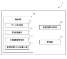
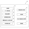
- FIG. 1 is a functional block diagram of the chlorine injection concentration control device 1 according to the present embodiment.
- the chlorine injection concentration control device 1 includes a control unit 11, a residual chlorine analysis unit 12, and a storage unit 13.
- the control unit 11 is a part that controls the entire chlorine injection concentration control device 1, and is executed by appropriately reading and executing various programs from a storage area such as a ROM, RAM, flash memory, or hard disk (HDD). It realizes various functions in the form.
- the control unit 11 may be a CPU.
- the control unit 11 includes a data acquisition unit 111, a relational calculation unit 112, a target concentration acquisition unit 113, and an optimum chlorine injection rate calculation unit 114.
- control unit 11 includes general functional blocks such as a functional block for controlling the entire chlorine injection concentration management device 1 and a functional block for performing communication.
- general functional blocks such as a functional block for controlling the entire chlorine injection concentration management device 1 and a functional block for performing communication.
- these general functional blocks are well known to those skilled in the art, illustration and description thereof will be omitted.
- the data acquisition unit 111 describes the injection rate of chlorine injected from the chlorine injection port in the seawater utilization plant and the condensate installed in the seawater utilization plant a predetermined time after injecting chlorine from the chlorine injection port at the injection rate.
- the "injection rate” is the amount of chlorine injected per hour, and is converted from the electrolytic current value. More specifically, in a seawater electrolyzer, increasing the electrolytic current value increases the amount of injected chlorine.
- the relationship between the electrolytic current value and the amount of injected chlorine is mathematically expressed, but the mathematical expression changes in the long term due to deterioration of the electrode, adhesion of calcium to the electrode, and cleaning. Therefore, the residual chlorine concentration in the manual analysis at a specific electrolytic current value is measured, and the mathematical formula is reviewed regularly.
- the injection rate is calculated by applying the electrolytic current value to the formula that is reviewed regularly.
- the condenser when the condenser is located about 500 m downstream from the chlorine inlet and the average flow velocity of the seawater used is about 0.8 m / s, even if the above predetermined time is set to about 10 minutes. Good.
- the data acquisition unit 111 inputs the value input from the GUI (Graphical User Interface) displayed on the display screen of the chlorine injection concentration management device 1 by the user of the chlorine injection concentration management device 1 to the chlorine. It may be acquired as data on the injection rate and the residual chlorine concentration. Alternatively, the measured value of the residual chlorine concentration at the inlet of the condenser continuously analyzed by the residual chlorine analysis unit 12 described later may be acquired as the data of the residual chlorine concentration.
- GUI Graphic User Interface
- the relational calculus unit 112 is based on the data of at least two sets of the chlorine injection rate and the residual chlorine concentration at the inlet of the condenser acquired by the data acquisition unit 111, and the chlorine injection rate and the condenser are restored.
- the relationship with the residual chlorine concentration at the inlet of the vessel is exponentially approximated.
- the relational calculation unit 112 approximates the relationship between the chlorine injection rate and the residual chlorine concentration at the inlet of the condenser by an index approximation, so that the chlorine injection rate is on the horizontal axis and the residual chlorine concentration at the inlet of the condenser is on the vertical axis.
- the relationship between the injection rate and the residual chlorine concentration can be represented by a straight line.
- the target concentration acquisition unit 113 acquires the target value of the residual chlorine concentration at the inlet of the condenser. As will be described later, the target concentration acquisition unit 113 sets a value input by the user of the chlorine injection concentration management device 1 from the GUI displayed on the display screen of the chlorine injection concentration management device 1, for example, as a target value of the residual chlorine concentration. May be obtained as.
- the optimum chlorine injection rate calculation unit 114 injects by applying the target value of the residual chlorine concentration acquired by the target concentration acquisition unit 113 to the relationship between the injection rate and the residual chlorine concentration index-approximate by the relational calculation unit 112. Calculate the optimum value of the rate.
- the user of the chlorine injection concentration control device 1 can grasp the optimum injection rate in order to achieve the target value of the residual chlorine concentration.
- the residual chlorine analysis unit 12 continuously measures the residual chlorine concentration at the inlet of the condenser, and outputs the measured value of the residual chlorine concentration to the data acquisition unit 111 each time the measurement is performed.
- the residual chlorine analyzer 12 can be realized by using, for example, a commercially available continuous analyzer.
- the storage unit 13 includes data obtained by the data acquisition unit 111 as a set of the chlorine injection rate and the residual chlorine concentration at the inlet of the condenser, and the chlorine injection rate exponentially approximated by the relational calculation unit 112.
- the relational calculus unit 112 reads out a plurality of data including the chlorine injection rate stored in the storage unit 13 and the residual chlorine concentration at the inlet of the condenser, and reads the chlorine injection rate and the condenser.
- the relationship with the residual chlorine concentration at the inlet may be exponentially approximated.
- the optimum chlorine injection rate calculation unit 114 may read out the relationship between the chlorine injection rate stored in the storage unit 13 and the residual chlorine concentration at the inlet of the condenser, and calculate the optimum injection rate. ..
- FIG. 2 is a diagram showing an example of a GUI displayed on the display screen of the chlorine injection concentration control device 1 described above.
- the user inputs the current chlorine injection rate in the input field d11 and the residual chlorine concentration at the current condenser inlet in the input field d12.
- the user inputs the changed chlorine injection rate in the input field d21, and inputs the residual chlorine concentration at the condenser inlet after a predetermined time after changing the chlorine injection rate in the input field d22. ..
- the user inputs the current water temperature in the input field t1.
- the user inputs the target value of the residual chlorine concentration at the condenser inlet in the input field o1.
- the user specifies the date of the past exponential approximation curve to be displayed as a reference in the input field p1.
- the chlorine injection rate and the index approximation curve of the residual chlorine concentration at the condenser inlet, the target value of the residual chlorine concentration at the condenser inlet, the initial residual chlorine concentration at the condenser inlet, and the chlorine injection are displayed in the display column m1.
- the residual chlorine concentration at the condenser inlet after changing the rate and the specified past exponential approximation curve are displayed.
- the optimum chlorine injection rate which is the target concentration at the inlet of the condenser, is displayed.
- FIG. 3 is a flowchart showing the operation of the chlorine injection concentration control device 1.
- the data acquisition unit 111 determines the injection rate of chlorine to be injected from the chlorine injection port and the residual chlorine concentration at the inlet of the condenser after a predetermined time after injecting chlorine from the chlorine injection port at the injection rate. Acquire the first set of data consisting of.
- step S12 the data acquisition unit 111 has the changed injection rate of chlorine injected from the chlorine injection port and the inlet of the condenser after a predetermined time after injecting chlorine from the chlorine injection port at the injection rate.
- the second set of data consisting of the residual chlorine concentration in is acquired.
- step S13 the relational calculation unit 112 approximately approximates the relationship between the chlorine injection rate and the residual chlorine concentration.
- step S14 the target concentration acquisition unit 113 acquires the target value of the residual chlorine concentration at the inlet of the condenser.
- step S15 the optimum chlorine injection rate calculation unit 114 calculates the optimum value of the chlorine injection rate from the relationship between the exponentially approximated chlorine injection rate and the residual chlorine concentration.
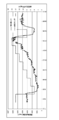
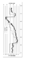
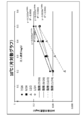
- FIG. 4A is a graph showing the time-series changes in the set injection rate of chlorine and the residual chlorine concentration at the condenser inlet, which were measured on July 5, 2018.
- FIG. 4B is a graph showing the time-series changes in the set injection rate of chlorine and the residual chlorine concentration at the condenser inlet, which were measured on August 8, 2018.
- FIG. 4C is a graph showing the time-series changes in the set injection rate of chlorine and the residual chlorine concentration at the condenser inlet, which were measured on September 14, 2018.
- FIG. 4D is a graph showing the time-series changes in the set injection rate of chlorine and the residual chlorine concentration at the condenser inlet, which were measured on November 7, 2018.
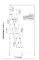
- FIG. 5 is a semi-logarithmic graph in which each average value is plotted on the vertical axis (logarithmic axis) and the set injection rate corresponding to the average value is plotted on the horizontal axis.
- the injection rate using the data measured on any of July 5, 2018, August 8, 2018, September 14, 2018, and November 7, 2018. Is shown as a straight line on a semi-log graph with the horizontal axis and the residual chlorine concentration on the vertical axis (logarithmic axis), indicating that the relationship between the injection rate and the residual chlorine concentration can be exponentially approximated.
- seawater was separated into flasks, kept at a constant temperature in a constant temperature water tank, sodium hypochlorite was added, and the residual chlorine concentration was measured at predetermined time intervals.
- the sodium hypochlorite to be added was defined in advance, and the chlorine concentration (calculated value) when a certain amount of this solution was added to the seawater sample was used as the initial chlorine injection concentration.
- the residual chlorine concentration was determined by developing a color by the tolidine method and measuring the absorbance.
- the calibration curve was obtained in advance from the absorbance of the residual chlorine standard colorimetric solution (mixture of potassium chromate-potassium dichromate solution and phosphate buffer), and the concentration was calculated from this.
- the measurement wavelength at this time was 440 nm.
- FIG. 6A shows chlorine injection into seawater at a water temperature of 10 ° C. in the seawater collected on July 26, 2005, September 26, 2005, December 2, 2005, and January 24, 2006, respectively. It is a semi-log graph in which the injection rate when sodium hypochlorite is added) is plotted on the horizontal axis, and the residual chlorine concentration 10 minutes after chlorine injection is plotted on the vertical axis (logarithmic axis).
- FIG. 6B shows the injection rate when chlorine is injected into seawater at a water temperature of 20 ° C. on July 26, 2005, September 26, 2005, December 2, 2005, and January 24, 2006, respectively.
- FIG. 6C shows chlorine injection into seawater at a water temperature of 30 ° C. in the seawater collected on July 26, 2005, September 26, 2005, December 2, 2005, and January 24, 2006, respectively. It is a semi-logarithmic graph in which the injection rate is plotted on the horizontal axis and the residual chlorine concentration 10 minutes after chlorine injection is plotted on the vertical axis (logarithmic axis).
- the chlorine injection concentration control device 1 has a set of a certain injection rate and a residual chlorine concentration at the condenser inlet after a predetermined time after injecting chlorine at the injection rate, and , A set of injection rates different from this and the residual chlorine concentration at the condenser inlet after a predetermined time after injecting chlorine at the injection rate, based on the above two sets of data, the injection rate and the residual chlorine concentration The optimum value of the injection rate was calculated from this relationship and the target value of the residual chlorine concentration at the condenser inlet.
- the chlorine injection concentration control device 1A has a residual chlorine concentration at the outlet based on a target value of the residual chlorine concentration that would be realized when chlorine is injected at the above optimum value.
- a target value of the residual chlorine concentration that would be realized when chlorine is injected at the above optimum value.
- FIG. 7 is a functional block diagram of the chlorine injection concentration control device 1A according to the present embodiment. Note that, in FIG. 7, among the components included in the chlorine injection concentration control device 1A, the same components as the components included in the chlorine injection concentration control device 1 are shown using the same reference numerals, and the functions thereof will be described below. Is basically omitted.
- the chlorine injection concentration control device 1A includes a control unit 11A instead of the control unit 11.
- the control unit 11A includes a predicted value calculation unit 115 in addition to the components included in the control unit 11.
- the chlorine injection concentration control device 1A includes a second residual chlorine analysis unit 14 and an alarm unit 15 in addition to the components included in the chlorine injection concentration control device 1.
- the predicted value calculation unit 115 predicts the residual chlorine concentration at the outlet based on the target value of the residual chlorine concentration at the condenser inlet acquired by the target concentration acquisition unit 113 and the water temperature at the condenser outlet. Calculate the value. In addition, when calculating the predicted value, the predicted value calculation unit 115 calculates the predicted value using the theoretical formula shown in [2.3 theoretical formula] described later.
- the second residual chlorine analysis unit 14 continuously measures the residual chlorine concentration at the outlet, and outputs the measured value of the residual chlorine concentration to the alarm unit 116 each time the measurement is performed.
- the second residual chlorine analysis unit 14 can be realized by using, for example, a commercially available continuous analyzer.
- the user of the chlorine injection concentration control device 1A can inject chlorine at the optimum injection rate in order to achieve the predicted value of the residual chlorine concentration at the outlet, while the measured value of the residual chlorine at the outlet can be measured. , It is possible to recognize this deviation when the distance is more than a certain distance from the predicted value.
- reaction rate constant k is explained by the Arrhenius equation, and increases as the water temperature rises, as shown in the following equation.
- A is a constant.
- E a hypochlorite ions generated as a result of the chlorine injection into seawater
- the reaction with hypobromite ions and seawater ingredients are intrinsic activation energy, for example, by location and time of the plant Is a constant of.
- R is the gas constant
- T is the water temperature (K) at the outlet of the condenser.
- E a / R is replaced with the constant B here, Will be. That is, since A and B are constants, the reaction rate constant k can be calculated from the water temperature T, and the residual chlorine concentration at the outlet can be predicted from the residual chlorine concentration at the condenser inlet.
- the residual chlorine concentration at the inlet of the condenser and the residual chlorine concentration at the outlet are substituted into the mathematical formula (2), and at least two sets of actually measured values are substituted.
- a plurality of reaction rate constants k are calculated.
- the residual chlorine concentration at the outlet the residual chlorine concentration after being allowed to stand for a predetermined time (for example, 4 minutes) from the residual chlorine concentration at the condenser inlet substituted in the formula (2) may be used. ..
- the plurality of ks obtained in the first step and the condenser outlet or outlet water temperature at the time of actual measurement corresponding to each k are substituted into the formula (6), and A and B are calculated respectively. To do.
- the coefficients A and B obtained in the second step and the water temperature at the current condenser outlet or outlet are substituted into the mathematical formula (6) to calculate the reaction rate constant k.
- the reaction rate constant k and the residual chlorine concentration at the condenser inlet are used to predict the residual chlorine concentration at the outlet.
- the chlorine injection concentration control device is a chlorine injection concentration control device for a seawater utilization plant, and has a chlorine injection rate to be injected from a chlorine injection port in the seawater utilization plant.
- a data acquisition unit 111 that acquires a set of data of the residual chlorine concentration at the inlet of the water recovery device installed in the seawater utilization plant after a predetermined time from the injection, and at least two sets of the injection rate and the residual chlorine concentration.
- the relation calculation unit 112 that exponentially approximates the relationship between the injection rate and the residual chlorine concentration
- the target concentration acquisition unit 113 that acquires the target value of the residual chlorine concentration, the target value of the residual chlorine concentration, and the index.
- the optimum chlorine injection rate calculation unit 114 for calculating the optimum value of the injection rate based on the approximated relationship is provided. This makes it possible to match the residual chlorine concentration at the condenser inlet to the target value without requiring complicated procedures as compared with the conventional technique.
- the chlorine injection concentration control device continuously measures the residual chlorine concentration at the inlet of the condenser, and outputs the measured value of the residual chlorine concentration to the data acquisition unit.
- the residual chlorine analysis unit 12 is further provided. This allows the user of the chlorine injection concentration control device to automatically measure the residual chlorine concentration at the condenser inlet without manual analysis.
- the chlorine injection concentration control device is installed in the seawater utilization plant based on the target value of the residual chlorine concentration and the water temperature at the outlet or the discharge port of the condenser. It is further provided with a predicted value calculation unit for calculating a predicted value of the residual chlorine concentration at the outlet. As a result, the user of the chlorine injection concentration control device can grasp the optimum injection rate for maintaining the residual chlorine concentration at the outlet at the environmental conservation agreement value.
- the second residual chlorine analysis unit 14 and the second residual chlorine analysis unit 14 continuously measure the residual chlorine concentration at the outlet. Further provided is an alarm unit 116 that issues an alarm when the difference between the measured residual chlorine concentration and the predicted value exceeds a predetermined value.
- the user of the chlorine injection concentration control device can inject chlorine at the optimum injection rate in order to realize the predicted value of the residual chlorine concentration at the outlet, while measuring the measured value of the residual chlorine at the outlet. When there is a deviation of a certain amount or more from the predicted value, this deviation can be recognized. When the separation is recognized, it is necessary to review the condenser inlet target value.
- the chlorine injection concentration control device 1 according to the first embodiment includes a residual chlorine analysis unit 12, and the chlorine injection concentration control device 1A according to the second embodiment further includes a second residual chlorine analysis unit 14.
- the residual chlorine analysis unit 12 and / or the second residual chlorine analysis unit 14 is not an essential component, and instead, the user of the chlorine injection concentration control device 1 or 1A can use the residual chlorine measured, for example, by hand analysis.
- the concentration may be manually entered for the chlorine injection concentration control device 1 or 1A.
- the relational calculation unit 112 of the chlorine injection concentration control device 1 according to the first embodiment and the chlorine injection concentration control device 1A according to the second embodiment has at least two sets of the chlorine injection rate and the residual chlorine at the inlet of the condenser. Based on the set of data with the concentration, the relationship between the chlorine injection rate and the residual chlorine concentration at the inlet of the condenser is exponentially approximated, but the relationship is not limited to this.
- the relational calculus unit 112 has a set of data of a set of chlorine injection rates and a residual chlorine concentration at the inlet of the water recovery device, and a zero point, that is, data in which both the injection rate and the residual chlorine concentration are zero.
- the above relationship may be exponentially approximated using data in which the injection rate is zero and the residual chlorine concentration is a predetermined value (for example, 0.01 mg / L).
- the management method by the chlorine injection concentration control device 1 or 1A is realized by software.
- the programs that make up this software are installed in a computer (chlorine injection concentration control device 1 or 1A).
- these programs may be recorded on removable media and distributed to users, or may be distributed by being downloaded to a user's computer via a network. Further, these programs may be provided to the user's computer (chlorine injection concentration control device 1 or 1A) as a Web service via the network without being downloaded.
Abstract
Provided is a chlorine injection concentration management device which makes it possible to align a residual chlorine concentration at a condenser intake port to a target value without necessitating a complicated procedure, as compared to the prior art. A chlorine injection concentration management device 1 for a seawater utilization plant, the device comprising: a data acquisition unit 111 that acquires data of a set including an injection rate of chlorine being injected in from a chlorine injection port in the seawater utilization plant, and the residual chlorine concentration after a predetermined length of time following injection, the residual chlorine concentration being at an inlet port of a condenser that is installed in the seawater utilization plant; a relationship computation unit 112 that takes an exponential approximation of the relationship between the injection rate and the residual chlorine concentration on the basis of data for at least two sets of the injection rate and the residual chlorine concentration; a target concentration acquisition unit 113 that acquires a target value for the residual chlorine concentration; and an optimum chlorine injection rate calculation unit 114 that calculates an optimum value for the injection rate on the basis of the target value for the residual chlorine concentration and the relationship for which the exponential approximation was taken.
Description
本発明は、塩素注入濃度管理装置、塩素注入濃度管理方法、及び塩素注入濃度管理プログラムに関する。より詳しくは、発電所等の海水利用プラントで用いられる塩素注入濃度管理装置、塩素注入濃度管理方法、及び塩素注入濃度管理プログラムに関する。
The present invention relates to a chlorine injection concentration control device, a chlorine injection concentration control method, and a chlorine injection concentration control program. More specifically, the present invention relates to a chlorine injection concentration control device, a chlorine injection concentration control method, and a chlorine injection concentration control program used in a seawater utilization plant such as a power plant.
火力・原子力発電所をはじめとする海水利用プラントの海水系統に付着する、フジツボ類、イガイ類等の付着生物、及びバイオフィルムへの対策として、海水電解塩素(次亜塩素酸ソーダ)の注入が広く実施されている。
Injection of seawater electrolytic chlorine (sodium hypochlorite) is a countermeasure against sessile organisms such as barnacles and mussels that adhere to the seawater system of seawater utilization plants such as thermal power plants and nuclear power plants, and biofilms. Widely implemented.
例えば、特許文献1は、天然の海水を電気分解することにより次亜塩素酸ソーダを生成し、当該次亜塩素酸ソーダを含む電解液を、海水の取水口に注入して海洋生物の付着防止に用いる技術を開示している。
For example, in Patent Document 1, sodium hypochlorite is produced by electrolyzing natural seawater, and an electrolytic solution containing the sodium hypochlorite is injected into the intake of seawater to prevent the adhesion of marine organisms. The technology used for is disclosed.
海水に電解塩素(次亜塩素酸ソーダ)を注入すると、速やかに濃度が減衰するが、減衰速度は水温、水質に左右されることから、水温、水質が日々変動する条件下において、付着生物やバイオフィルムの付着を抑制すると共に、海水利用プラントの放水口における環境保全協定値としての残留塩素濃度(例えば、0.02mg/L)を維持することは非常に困難となる。現状では、環境保全協定値の順守を優先し、電解塩素の注入濃度を控えめにしていることから、付着生物やバイオフィルムの付着抑制効果は十分に得られていない。
When electrolytic chlorine (sodium hypochlorite) is injected into seawater, the concentration rapidly decreases, but the rate of decay depends on the water temperature and quality, so under conditions where the water temperature and quality fluctuate daily, sessile organisms and It is very difficult to suppress the adhesion of biofilm and maintain the residual chlorine concentration (for example, 0.02 mg / L) as the environmental conservation agreement value at the outlet of the seawater utilization plant. At present, since compliance with the environmental conservation agreement values is prioritized and the injection concentration of electrolytic chlorine is conservative, the effect of suppressing the adhesion of attached organisms and biofilms has not been sufficiently obtained.
現状では、一週間に一回程度、復水器入口で手分析で残留塩素濃度を確認しながら濃度調整を実施しているが、あくまで運転員の経験に基づく調整によるものであり、明確な根拠に基づく理論的な調整方法が従来までなかった。また、電解塩素の注入率を変更した後に、変更が復水器入口に反映されるまで、貯留槽の容量や流下時間の影響により、30分~50分かかる。このため、残留塩素濃度の目標値に合わせるためには、何度も手分析を繰り返す必要があり煩雑であった。このことも、電解塩素の注入率が控えめに設定され、十分な付着抑制効果が得られない要因となっている。
At present, the concentration is adjusted while checking the residual chlorine concentration by hand analysis at the condenser inlet about once a week, but it is based on the operator's experience and has a clear basis. Until now, there has been no theoretical adjustment method based on. Further, after changing the injection rate of electrolytic chlorine, it takes 30 to 50 minutes depending on the capacity of the storage tank and the flow time until the change is reflected at the inlet of the condenser. Therefore, in order to match the target value of the residual chlorine concentration, it is necessary to repeat the manual analysis many times, which is complicated. This is also a factor that the injection rate of electrolytic chlorine is set conservatively, and a sufficient adhesion suppressing effect cannot be obtained.
本発明は、上記課題に鑑みてなされたものであり、従来技術に比較して、煩雑な手続を必要とせずに、復水器入口での残留塩素濃度を目標値に合わせることが可能な、塩素注入濃度管理装置を提供することを目的とする。
The present invention has been made in view of the above problems, and it is possible to adjust the residual chlorine concentration at the inlet of the condenser to a target value without requiring complicated procedures as compared with the prior art. An object of the present invention is to provide a chlorine injection concentration control device.
本発明は、海水利用プラントのための塩素注入濃度管理装置であって、前記海水利用プラントにおける塩素注入口から注入する塩素の注入率と、前記注入から所定時間後の、前記海水利用プラントに設置される復水器の入口における残留塩素濃度との組のデータを取得するデータ取得部と、少なくとも二組の前記注入率と前記残留塩素濃度とのデータに基づいて、前記注入率と前記残留塩素濃度との関係を指数近似する関係演算部と、前記残留塩素濃度の目標値を取得する目標濃度取得部と、前記残留塩素濃度の目標値と、指数近似された前記関係とに基づいて、前記注入率の目標値を算出する目標注入率算出部と、を備える、塩素注入濃度管理装置に関する。
The present invention is a chlorine injection concentration control device for a seawater utilization plant, which is installed in the seawater utilization plant after the injection rate of chlorine injected from the chlorine injection port in the seawater utilization plant and a predetermined time after the injection. Based on the data acquisition unit that acquires the set data of the residual chlorine concentration at the inlet of the water condenser, and at least two sets of the injection rate and the residual chlorine concentration, the injection rate and the residual chlorine Based on the relationship calculation unit that exponentially approximates the relationship with the concentration, the target concentration acquisition unit that acquires the target value of the residual chlorine concentration, the target value of the residual chlorine concentration, and the exponentially approximated relationship. The present invention relates to a chlorine injection concentration management device including a target injection rate calculation unit for calculating a target value of the injection rate.
また、前記復水器の入口において前記残留塩素濃度を連続的に測定し、前記残留塩素濃度の実測値を前記データ入力部に出力する残留塩素分析部を更に備えることが好ましい。
Further, it is preferable to further include a residual chlorine analysis unit that continuously measures the residual chlorine concentration at the inlet of the condenser and outputs the measured value of the residual chlorine concentration to the data input unit.
また、前記残留塩素濃度の目標値と前記復水器の出口での水温とに基づいて、前記海水利用プラントに設置される放水口での残留塩素濃度の予測値を算出する予測値算出部を更に備えることが好ましい。
In addition, a predicted value calculation unit that calculates a predicted value of the residual chlorine concentration at the outlet installed in the seawater utilization plant based on the target value of the residual chlorine concentration and the water temperature at the outlet of the condenser. Further provision is preferred.
また、前記放水口での残留塩素濃度を連続的に測定する第二残留塩素分析部と、前記第二残留塩素分析部によって測定された前記残留塩素濃度と、前記予測値との差分が所定値を超えた場合に警報を発報する警報部と、を更に備えることが好ましい。
Further, the difference between the second residual chlorine analysis unit that continuously measures the residual chlorine concentration at the outlet, the residual chlorine concentration measured by the second residual chlorine analysis unit, and the predicted value is a predetermined value. It is preferable to further include an alarm unit that issues an alarm when the above value is exceeded.
また本発明は、海水利用プラントのための塩素注入濃度管理方法であって、前記海水利用プラントにおける塩素注入口から注入する塩素の注入率と、前記注入から所定時間後の、前記海水利用プラントに設置される復水器の入口における残留塩素濃度との組のデータを取得するデータ取得ステップと、少なくとも二組の前記注入率と前記残留塩素濃度とのデータに基づいて、前記注入率と前記残留塩素濃度との関係を指数近似する関係演算ステップと、前記残留塩素濃度の目標値を取得する目標濃度取得ステップと、前記残留塩素濃度の目標値と、指数近似された前記関係とに基づいて、前記注入率の最適値を算出する最適塩素注入率算出ステップと、を有する、塩素注入濃度管理方法に関する。
The present invention is a chlorine injection concentration control method for a seawater utilization plant, wherein the chlorine injection rate to be injected from the chlorine injection port in the seawater utilization plant and a predetermined time after the injection into the seawater utilization plant. The injection rate and the residual chlorine concentration are based on a data acquisition step of acquiring a set of data of the residual chlorine concentration at the inlet of the water concentrator installed and at least two sets of the injection rate and the residual chlorine concentration data. Based on the relationship calculation step that exponentially approximates the relationship with the chlorine concentration, the target concentration acquisition step that acquires the target value of the residual chlorine concentration, the target value of the residual chlorine concentration, and the exponentially approximated relationship. The present invention relates to a chlorine injection concentration control method having an optimum chlorine injection rate calculation step for calculating the optimum value of the injection rate.
また本発明は、海水利用プラントのための塩素注入濃度管理プログラムであって、前記海水利用プラントにおける塩素注入口から注入する塩素の注入率と、前記注入から所定時間後の、前記海水利用プラントに設置される復水器の入口における残留塩素濃度との組のデータを取得するデータ取得ステップと、少なくとも二組の前記注入率と前記残留塩素濃度とのデータに基づいて、前記注入率と前記残留塩素濃度との関係を指数近似する関係演算ステップと、前記残留塩素濃度の目標値を取得する目標濃度取得ステップと、前記残留塩素濃度の目標値と、指数近似された前記関係とに基づいて、前記注入率の最適値を算出する最適塩素注入率算出ステップと、をコンピュータに実行させるための、塩素注入濃度管理プログラムに関する。
Further, the present invention is a chlorine injection concentration control program for a seawater utilization plant, in which the chlorine injection rate to be injected from the chlorine injection port in the seawater utilization plant and the chlorine injection rate to the seawater utilization plant after a predetermined time from the injection. The injection rate and the residual chlorine concentration are based on a data acquisition step of acquiring a set of data of the residual chlorine concentration at the inlet of the water concentrator installed and at least two sets of the injection rate and the residual chlorine concentration data. Based on the relationship calculation step that exponentially approximates the relationship with the chlorine concentration, the target concentration acquisition step that acquires the target value of the residual chlorine concentration, the target value of the residual chlorine concentration, and the exponentially approximated relationship. The present invention relates to an optimum chlorine injection rate calculation step for calculating the optimum value of the injection rate, and a chlorine injection concentration control program for causing a computer to execute the step.
従来技術に比較して、煩雑な手続を必要とせずに、復水器入口での残留塩素濃度を目標値に合わせることが可能となる。
Compared with the conventional technology, it is possible to adjust the residual chlorine concentration at the condenser inlet to the target value without requiring complicated procedures.
以下、本発明の実施形態について図面を参照しながら説明する。
〔1 第1実施形態〕
〔1.1 発明の概要〕
後述の試験データに示すように、発電所の実機において復水器入口に連続式の残留塩素濃度分析計を設置し、塩素注入口から注入する塩素の注入率、すなわち1時間当たりの注入塩素量を変化させながら、復水器入口における残留塩素濃度を分析した所、どの季節、どの水温でも、注入率と残留塩素濃度の関係を指数近似できることが判明した。すなわち、注入率を横軸に、残留塩素濃度を縦軸にグラフ化した場合、片対数グラフを用いれば、注入率と残留塩素濃度との関係を直線で示すことが可能となる。 Hereinafter, embodiments of the present invention will be described with reference to the drawings.
[1 First Embodiment]
[1.1 Outline of the Invention]
As shown in the test data described later, a continuous residual chlorine concentration analyzer is installed at the inlet of the condenser in the actual machine of the power plant, and the injection rate of chlorine injected from the chlorine inlet, that is, the amount of chlorine injected per hour. When the residual chlorine concentration at the condenser inlet was analyzed while changing the above, it was found that the relationship between the injection rate and the residual chlorine concentration could be exponentially approximated at any season and at any water temperature. That is, when the injection rate is graphed on the horizontal axis and the residual chlorine concentration is graphed on the vertical axis, the relationship between the injection rate and the residual chlorine concentration can be shown by a straight line by using a semi-logarithmic graph.
これに基づいて、ある注入率と、当該注入率で塩素を注入してから所定時間後の復水器入口における残留塩素濃度との組、及び、これとは異なる注入率と、当該注入率で塩素を注入してから所定時間後の復水器入口における残留塩素濃度との組、以上二組のデータに基づいて、注入率と残留塩素濃度との関係を導き出す。この関係と、復水器入口における残留塩素濃度の目標値とから、注入率の最適値を算出する。
Based on this, a set of a certain injection rate and the residual chlorine concentration at the condenser inlet after a predetermined time after injecting chlorine at the injection rate, and an injection rate different from this and the injection rate The relationship between the injection rate and the residual chlorine concentration is derived based on the set of the residual chlorine concentration at the condenser inlet after a predetermined time after the injection of chlorine and the above two sets of data. From this relationship and the target value of the residual chlorine concentration at the condenser inlet, the optimum value of the injection rate is calculated.
これにより、何度も手分析を繰り返す等の煩雑な手続をする必要なく、目標となる残留塩素濃度を達成することが可能となる。
This makes it possible to achieve the target residual chlorine concentration without the need for complicated procedures such as repeating manual analysis many times.
〔1.2 実施形態の構成〕
図1は、本実施形態に係る塩素注入濃度管理装置1の機能ブロック図である。塩素注入濃度管理装置1は、制御部11、残留塩素分析部12、及び記憶部13を備える。 [1.2 Configuration of Embodiment]
FIG. 1 is a functional block diagram of the chlorine injectionconcentration control device 1 according to the present embodiment. The chlorine injection concentration control device 1 includes a control unit 11, a residual chlorine analysis unit 12, and a storage unit 13.
図1は、本実施形態に係る塩素注入濃度管理装置1の機能ブロック図である。塩素注入濃度管理装置1は、制御部11、残留塩素分析部12、及び記憶部13を備える。 [1.2 Configuration of Embodiment]
FIG. 1 is a functional block diagram of the chlorine injection
制御部11は、塩素注入濃度管理装置1の全体を制御する部分であり、各種プログラムを、ROM、RAM、フラッシュメモリ又はハードディスク(HDD)等の記憶領域から適宜読み出して実行することにより、本実施形態における各種機能を実現している。制御部11は、CPUであってよい。制御部11は、データ取得部111、関係演算部112、目標濃度取得部113、及び最適塩素注入率算出部114を備える。
The control unit 11 is a part that controls the entire chlorine injection concentration control device 1, and is executed by appropriately reading and executing various programs from a storage area such as a ROM, RAM, flash memory, or hard disk (HDD). It realizes various functions in the form. The control unit 11 may be a CPU. The control unit 11 includes a data acquisition unit 111, a relational calculation unit 112, a target concentration acquisition unit 113, and an optimum chlorine injection rate calculation unit 114.
また、制御部11は、それ以外にも、塩素注入濃度管理装置1の全体を制御するための機能ブロック、通信を行うための機能ブロックといった一般的な機能ブロックを備える。ただし、これらの一般的な機能ブロックについては当業者によく知られているので図示及び説明を省略する。
In addition, the control unit 11 includes general functional blocks such as a functional block for controlling the entire chlorine injection concentration management device 1 and a functional block for performing communication. However, since these general functional blocks are well known to those skilled in the art, illustration and description thereof will be omitted.
データ取得部111は、海水利用プラントにおける塩素注入口から注入する塩素の注入率と、当該注入率で塩素注入口から塩素を注入してから所定時間後の、海水利用プラントに設置される復水器の入口における残留塩素濃度とを組とするデータを取得する。なお、ここで「注入率」とは、1時間当たりの注入塩素量であり、電解電流値から換算される。
より詳細には、海水電解装置において、電解電流値を上げれば注入塩素量が上がる。この電解電流値と注入塩素量の関係は数式化されているが、電極の劣化、電極へのカルシウムの付着、洗浄の実施などにより、長期的には数式は変化する。そこで、特定の電解電流値における手分析の残留塩素濃度を計測して、数式を定期的に見直す。当該定期的に見直される数式に対し電解電流値を適用することにより、注入率を算出する。 Thedata acquisition unit 111 describes the injection rate of chlorine injected from the chlorine injection port in the seawater utilization plant and the condensate installed in the seawater utilization plant a predetermined time after injecting chlorine from the chlorine injection port at the injection rate. Obtain data that is paired with the residual chlorine concentration at the inlet of the vessel. Here, the "injection rate" is the amount of chlorine injected per hour, and is converted from the electrolytic current value.
More specifically, in a seawater electrolyzer, increasing the electrolytic current value increases the amount of injected chlorine. The relationship between the electrolytic current value and the amount of injected chlorine is mathematically expressed, but the mathematical expression changes in the long term due to deterioration of the electrode, adhesion of calcium to the electrode, and cleaning. Therefore, the residual chlorine concentration in the manual analysis at a specific electrolytic current value is measured, and the mathematical formula is reviewed regularly. The injection rate is calculated by applying the electrolytic current value to the formula that is reviewed regularly.
より詳細には、海水電解装置において、電解電流値を上げれば注入塩素量が上がる。この電解電流値と注入塩素量の関係は数式化されているが、電極の劣化、電極へのカルシウムの付着、洗浄の実施などにより、長期的には数式は変化する。そこで、特定の電解電流値における手分析の残留塩素濃度を計測して、数式を定期的に見直す。当該定期的に見直される数式に対し電解電流値を適用することにより、注入率を算出する。 The
More specifically, in a seawater electrolyzer, increasing the electrolytic current value increases the amount of injected chlorine. The relationship between the electrolytic current value and the amount of injected chlorine is mathematically expressed, but the mathematical expression changes in the long term due to deterioration of the electrode, adhesion of calcium to the electrode, and cleaning. Therefore, the residual chlorine concentration in the manual analysis at a specific electrolytic current value is measured, and the mathematical formula is reviewed regularly. The injection rate is calculated by applying the electrolytic current value to the formula that is reviewed regularly.
また、例えば、復水器が塩素注入口から約500m下流に位置し、利用する海水の平均流速が0.8m/s程度の場合、上記の所定時間として10分程度の時間を設定してもよい。
Further, for example, when the condenser is located about 500 m downstream from the chlorine inlet and the average flow velocity of the seawater used is about 0.8 m / s, even if the above predetermined time is set to about 10 minutes. Good.
更に、データ取得部111は、後述のように、塩素注入濃度管理装置1のユーザが、塩素注入濃度管理装置1の表示画面に表示されるGUI(Graphical User Interface)から入力した値を、塩素の注入率や残留塩素濃度のデータとして取得してもよい。あるいは、後述の残留塩素分析部12によって連続的に分析された復水器の入口における残留塩素濃度の測定値を、残留塩素濃度のデータとして取得してもよい。
Further, as described later, the data acquisition unit 111 inputs the value input from the GUI (Graphical User Interface) displayed on the display screen of the chlorine injection concentration management device 1 by the user of the chlorine injection concentration management device 1 to the chlorine. It may be acquired as data on the injection rate and the residual chlorine concentration. Alternatively, the measured value of the residual chlorine concentration at the inlet of the condenser continuously analyzed by the residual chlorine analysis unit 12 described later may be acquired as the data of the residual chlorine concentration.
関係演算部112は、データ取得部111によって取得された、少なくとも二組の、塩素の注入率と復水器の入口における残留塩素濃度との組のデータに基づいて、塩素の注入率と復水器の入口における残留塩素濃度との関係を指数近似する。
The relational calculus unit 112 is based on the data of at least two sets of the chlorine injection rate and the residual chlorine concentration at the inlet of the condenser acquired by the data acquisition unit 111, and the chlorine injection rate and the condenser are restored. The relationship with the residual chlorine concentration at the inlet of the vessel is exponentially approximated.
関係演算部112が、塩素の注入率と復水器の入口における残留塩素濃度との関係を指数近似することにより、塩素の注入率を横軸、復水器の入口における残留塩素濃度を縦軸とする片対数グラフにおいて、注入率と残留塩素濃度との関係を直線で表すことが可能となる。
The relational calculation unit 112 approximates the relationship between the chlorine injection rate and the residual chlorine concentration at the inlet of the condenser by an index approximation, so that the chlorine injection rate is on the horizontal axis and the residual chlorine concentration at the inlet of the condenser is on the vertical axis. In the semi-log graph, the relationship between the injection rate and the residual chlorine concentration can be represented by a straight line.
目標濃度取得部113は、復水器の入口における残留塩素濃度の目標値を取得する。目標濃度取得部113は、後述のように、塩素注入濃度管理装置1のユーザが、例えば、塩素注入濃度管理装置1の表示画面に表示されるGUIから入力した値を、残留塩素濃度の目標値として取得してもよい。
The target concentration acquisition unit 113 acquires the target value of the residual chlorine concentration at the inlet of the condenser. As will be described later, the target concentration acquisition unit 113 sets a value input by the user of the chlorine injection concentration management device 1 from the GUI displayed on the display screen of the chlorine injection concentration management device 1, for example, as a target value of the residual chlorine concentration. May be obtained as.
最適塩素注入率算出部114は、目標濃度取得部113によって取得された残留塩素濃度の目標値を、関係演算部112によって指数近似された注入率と残留塩素濃度との関係に当てはめることで、注入率の最適値を算出する。
The optimum chlorine injection rate calculation unit 114 injects by applying the target value of the residual chlorine concentration acquired by the target concentration acquisition unit 113 to the relationship between the injection rate and the residual chlorine concentration index-approximate by the relational calculation unit 112. Calculate the optimum value of the rate.
これにより、塩素注入濃度管理装置1のユーザは、残留塩素濃度の目標値を達成するために最適な注入率を把握することが可能となる。
As a result, the user of the chlorine injection concentration control device 1 can grasp the optimum injection rate in order to achieve the target value of the residual chlorine concentration.
残留塩素分析部12は、復水器の入口において残留塩素濃度を連続的に測定し、測定の都度、残留塩素濃度の実測値をデータ取得部111に出力する。この残留塩素分析部12は、例えば市販の連続分析計を用いて実現することが可能である。
The residual chlorine analysis unit 12 continuously measures the residual chlorine concentration at the inlet of the condenser, and outputs the measured value of the residual chlorine concentration to the data acquisition unit 111 each time the measurement is performed. The residual chlorine analyzer 12 can be realized by using, for example, a commercially available continuous analyzer.
記憶部13は、データ取得部111によって取得された、塩素の注入率と、復水器の入口における残留塩素濃度とを組とするデータや、関係演算部112によって指数近似された塩素の注入率と復水器の入口における残留塩素濃度との関係を記憶する。例えば、関係演算部112は、記憶部13に記憶された塩素の注入率と、復水器の入口における残留塩素濃度とを組とするデータを複数読み出して、塩素の注入率と復水器の入口における残留塩素濃度との関係を指数近似してもよい。また、最適塩素注入率算出部114は、記憶部13に記憶された、塩素の注入率と復水器の入口における残留塩素濃度との関係を読み出して、最適な注入率を算出してもよい。
The storage unit 13 includes data obtained by the data acquisition unit 111 as a set of the chlorine injection rate and the residual chlorine concentration at the inlet of the condenser, and the chlorine injection rate exponentially approximated by the relational calculation unit 112. Memorize the relationship between and the residual chlorine concentration at the inlet of the condenser. For example, the relational calculus unit 112 reads out a plurality of data including the chlorine injection rate stored in the storage unit 13 and the residual chlorine concentration at the inlet of the condenser, and reads the chlorine injection rate and the condenser. The relationship with the residual chlorine concentration at the inlet may be exponentially approximated. Further, the optimum chlorine injection rate calculation unit 114 may read out the relationship between the chlorine injection rate stored in the storage unit 13 and the residual chlorine concentration at the inlet of the condenser, and calculate the optimum injection rate. ..
図2は、上記の塩素注入濃度管理装置1の表示画面に表示されるGUIの一例を示す図である。
FIG. 2 is a diagram showing an example of a GUI displayed on the display screen of the chlorine injection concentration control device 1 described above.
最初のステップとして、ユーザは、入力欄d11に現在の塩素注入率を入力し、入力欄d12に現在の復水器入口における残留塩素濃度を入力する。
第2のステップとして、ユーザは、入力欄d21に変更後の塩素注入率を入力し、入力欄d22に塩素注入率を変更してから所定時間後の復水器入口における残留塩素濃度を入力する。
第3のステップとして、ユーザは、入力欄t1に現在の水温を入力する。
第4のステップとして、ユーザは、入力欄o1に、復水器入口における残留塩素濃度の目標値を入力する。
第5のステップとして、ユーザは、入力欄p1に、参考として表示する過去の指数近似曲線の日付を指定する。
これにより、表示欄m1に、塩素注入率と復水器入口における残留塩素濃度の指数近似曲線、復水器入口における残留塩素濃度の目標値、当初の復水器入口における残留塩素濃度、塩素注入率を変更した後の復水器入口における残留塩素濃度、指定した過去の指数近似曲線が表示される。
更に、表示欄r1に、復水器入口で目標濃度となる最適塩素注入率が表示される。 As a first step, the user inputs the current chlorine injection rate in the input field d11 and the residual chlorine concentration at the current condenser inlet in the input field d12.
As a second step, the user inputs the changed chlorine injection rate in the input field d21, and inputs the residual chlorine concentration at the condenser inlet after a predetermined time after changing the chlorine injection rate in the input field d22. ..
As a third step, the user inputs the current water temperature in the input field t1.
As a fourth step, the user inputs the target value of the residual chlorine concentration at the condenser inlet in the input field o1.
As a fifth step, the user specifies the date of the past exponential approximation curve to be displayed as a reference in the input field p1.
As a result, the chlorine injection rate and the index approximation curve of the residual chlorine concentration at the condenser inlet, the target value of the residual chlorine concentration at the condenser inlet, the initial residual chlorine concentration at the condenser inlet, and the chlorine injection are displayed in the display column m1. The residual chlorine concentration at the condenser inlet after changing the rate and the specified past exponential approximation curve are displayed.
Further, in the display column r1, the optimum chlorine injection rate, which is the target concentration at the inlet of the condenser, is displayed.
〔1.3 実施形態の動作〕
図3は、塩素注入濃度管理装置1の動作を示すフローチャートである。
ステップS11において、データ取得部111は、塩素注入口から注入する塩素の注入率と、当該注入率で塩素注入口から塩素を注入してから所定時間後の、復水器の入口における残留塩素濃度とからなる1組目のデータを取得する。 [1.3 Operation of the embodiment]
FIG. 3 is a flowchart showing the operation of the chlorine injectionconcentration control device 1.
In step S11, thedata acquisition unit 111 determines the injection rate of chlorine to be injected from the chlorine injection port and the residual chlorine concentration at the inlet of the condenser after a predetermined time after injecting chlorine from the chlorine injection port at the injection rate. Acquire the first set of data consisting of.
図3は、塩素注入濃度管理装置1の動作を示すフローチャートである。
ステップS11において、データ取得部111は、塩素注入口から注入する塩素の注入率と、当該注入率で塩素注入口から塩素を注入してから所定時間後の、復水器の入口における残留塩素濃度とからなる1組目のデータを取得する。 [1.3 Operation of the embodiment]
FIG. 3 is a flowchart showing the operation of the chlorine injection
In step S11, the
ステップS12において、データ取得部111は、変更後の、塩素注入口から注入する塩素の注入率と、当該注入率で塩素注入口から塩素を注入してから所定時間後の、復水器の入口における残留塩素濃度とからなる2組目のデータを取得する。
In step S12, the data acquisition unit 111 has the changed injection rate of chlorine injected from the chlorine injection port and the inlet of the condenser after a predetermined time after injecting chlorine from the chlorine injection port at the injection rate. The second set of data consisting of the residual chlorine concentration in is acquired.
ステップS13において、関係演算部112は、塩素の注入率と残留塩素濃度との関係を指数近似する。
In step S13, the relational calculation unit 112 approximately approximates the relationship between the chlorine injection rate and the residual chlorine concentration.
ステップS14において、目標濃度取得部113は、復水器の入口における残留塩素濃度の目標値を取得する。
In step S14, the target concentration acquisition unit 113 acquires the target value of the residual chlorine concentration at the inlet of the condenser.
ステップS15において、最適塩素注入率算出部114が、指数近似した塩素の注入率と残留塩素濃度の関係から、塩素の注入率の最適値を算出する。
In step S15, the optimum chlorine injection rate calculation unit 114 calculates the optimum value of the chlorine injection rate from the relationship between the exponentially approximated chlorine injection rate and the residual chlorine concentration.
〔1.4 試験データ〕
〔1.4.1 実地試験〕
岡山県倉敷市に立地する玉島発電所実機において、塩素を注入する取水口から約500m下流に位置する復水器入口に連続分析計を設置し、塩素の注入率と、塩素を注入してから約10分後相当の復水器入口における残留塩素濃度との関係を測定した。 [1.4 Test data]
[1.4.1 Field test]
At the actual Tamashima power plant located in Kurashiki City, Okayama Prefecture, a continuous analyzer was installed at the condenser inlet located about 500 m downstream from the chlorine injection intake, and the chlorine injection rate and chlorine injection were performed. After about 10 minutes, the relationship with the residual chlorine concentration at the condenser inlet was measured.
図4Aは、2018年7月5日に測定した、塩素の設定注入率と復水器入口における残留塩素濃度の時系列変化を示すグラフである。
図4Bは、2018年8月8日に測定した、塩素の設定注入率と復水器入口における残留塩素濃度の時系列変化を示すグラフである。
図4Cは、2018年9月14日に測定した、塩素の設定注入率と復水器入口における残留塩素濃度の時系列変化を示すグラフである。
図4Dは、2018年11月7日に測定した、塩素の設定注入率と復水器入口における残留塩素濃度の時系列変化を示すグラフである。 FIG. 4A is a graph showing the time-series changes in the set injection rate of chlorine and the residual chlorine concentration at the condenser inlet, which were measured on July 5, 2018.
FIG. 4B is a graph showing the time-series changes in the set injection rate of chlorine and the residual chlorine concentration at the condenser inlet, which were measured on August 8, 2018.
FIG. 4C is a graph showing the time-series changes in the set injection rate of chlorine and the residual chlorine concentration at the condenser inlet, which were measured on September 14, 2018.
FIG. 4D is a graph showing the time-series changes in the set injection rate of chlorine and the residual chlorine concentration at the condenser inlet, which were measured on November 7, 2018.
これらの各々のグラフの元データから、1時間間隔となる複数の時刻(注入濃度を変更した時刻)において、各々の時刻前後の10点(1分毎の瞬時データの10分間分)の残留塩素濃度をピックアップし、これらの平均値を算出した。
図5は、各平均値を縦軸(対数軸)に、当該平均値に対応する設定注入率を横軸にプロットした片対数グラフである。
図5から明らかなように、2018年7月5日、2018年8月8日、2018年9月14日、2018年11月7日のいずれの日に測定したデータを用いても、注入率を横軸、残留塩素濃度を縦軸(対数軸)とする片対数グラフ上に直線で示されることから、注入率と残留塩素濃度の関係は、指数近似可能であることが示された。 From the original data of each of these graphs, residual chlorine at 10 points (10 minutes of instantaneous data every minute) before and after each time at multiple times (time when the injection concentration was changed) at 1-hour intervals. The concentrations were picked up and the average value of these was calculated.
FIG. 5 is a semi-logarithmic graph in which each average value is plotted on the vertical axis (logarithmic axis) and the set injection rate corresponding to the average value is plotted on the horizontal axis.
As is clear from FIG. 5, the injection rate using the data measured on any of July 5, 2018, August 8, 2018, September 14, 2018, and November 7, 2018. Is shown as a straight line on a semi-log graph with the horizontal axis and the residual chlorine concentration on the vertical axis (logarithmic axis), indicating that the relationship between the injection rate and the residual chlorine concentration can be exponentially approximated.
〔1.4.2 室内試験〕
室内において、フラスコに海水を採取して塩素(次亜塩素酸ソーダ)を注入すると共に、塩素の注入から10分後の残留塩素濃度を測定した。試験は、2005年7月26日、2005年9月26日、2005年12月2日、2006年1月24日に山口県柳井市周辺海域において採取した海水について実施した。また、試験は水温10℃、20℃、30℃の3種類の温度設定をした海水に対して実施した。 [1.4.2 Laboratory test]
In the room, seawater was collected in a flask and chlorine (sodium hypochlorite) was injected, and theresidual chlorine concentration 10 minutes after the injection of chlorine was measured. The test was conducted on seawater collected in the waters around Yanai City, Yamaguchi Prefecture on July 26, 2005, September 26, 2005, December 2, 2005, and January 24, 2006. In addition, the test was carried out on seawater having three types of temperature settings of water temperature of 10 ° C., 20 ° C., and 30 ° C.
室内において、フラスコに海水を採取して塩素(次亜塩素酸ソーダ)を注入すると共に、塩素の注入から10分後の残留塩素濃度を測定した。試験は、2005年7月26日、2005年9月26日、2005年12月2日、2006年1月24日に山口県柳井市周辺海域において採取した海水について実施した。また、試験は水温10℃、20℃、30℃の3種類の温度設定をした海水に対して実施した。 [1.4.2 Laboratory test]
In the room, seawater was collected in a flask and chlorine (sodium hypochlorite) was injected, and the
より詳細には、海水をフラスコに分取した後、恒温水槽で一定温度に保持し、次亜塩素酸ソーダを添加し、所定時間ごとに残留塩素濃度を測定した。添加する次亜塩素酸ソーダは事前に標定しておき、この液を海水試料に一定量添加したときの塩素濃度(計算値)を初期塩素注入濃度とした。
残留塩素濃度は、オルト―トリジン法により発色させ、吸光度を測定し求めた。事前に残留塩素標準比色液(クロム酸カリウム-二クロム酸カリウム溶液とリン酸塩緩衝液の混合)の吸光度から検量線を求め、これにより濃度を算出した。このときの測定波長は440nmを用いた。 More specifically, seawater was separated into flasks, kept at a constant temperature in a constant temperature water tank, sodium hypochlorite was added, and the residual chlorine concentration was measured at predetermined time intervals. The sodium hypochlorite to be added was defined in advance, and the chlorine concentration (calculated value) when a certain amount of this solution was added to the seawater sample was used as the initial chlorine injection concentration.
The residual chlorine concentration was determined by developing a color by the tolidine method and measuring the absorbance. The calibration curve was obtained in advance from the absorbance of the residual chlorine standard colorimetric solution (mixture of potassium chromate-potassium dichromate solution and phosphate buffer), and the concentration was calculated from this. The measurement wavelength at this time was 440 nm.
図6Aは、2005年7月26日、2005年9月26日、2005年12月2日、及び2006年1月24日の各々に採水した海水における、水温10℃の海水に塩素注入(次亜塩素酸ソーダを添加)をした場合の注入率を横軸に、塩素注入から10分後の残留塩素濃度を縦軸(対数軸)にプロットした片対数グラフである。
図6Bは、2005年7月26日、2005年9月26日、2005年12月2日、及び2006年1月24日の各々における、水温20℃の海水に塩素注入をした場合の注入率を横軸に、塩素注入から10分後の残留塩素濃度を縦軸(対数軸)にプロットした片対数グラフである。
図6Cは、2005年7月26日、2005年9月26日、2005年12月2日、及び2006年1月24日の各々に採水した海水における、水温30℃の海水に塩素注入をした場合の注入率を横軸に、塩素注入から10分後の残留塩素濃度を縦軸(対数軸)にプロットした片対数グラフである。
いずれのグラフにおいても、注入率を横軸、残留塩素濃度を縦軸(対数軸)とする片対数グラフ上に直線で示されることから、注入率と残留塩素濃度の関係は、指数近似可能であることが示された。 FIG. 6A shows chlorine injection into seawater at a water temperature of 10 ° C. in the seawater collected on July 26, 2005, September 26, 2005, December 2, 2005, and January 24, 2006, respectively. It is a semi-log graph in which the injection rate when sodium hypochlorite is added) is plotted on the horizontal axis, and theresidual chlorine concentration 10 minutes after chlorine injection is plotted on the vertical axis (logarithmic axis).
FIG. 6B shows the injection rate when chlorine is injected into seawater at a water temperature of 20 ° C. on July 26, 2005, September 26, 2005, December 2, 2005, and January 24, 2006, respectively. Is a semi-logarithmic graph in which theresidual chlorine concentration 10 minutes after chlorine injection is plotted on the vertical axis (logarithmic axis).
FIG. 6C shows chlorine injection into seawater at a water temperature of 30 ° C. in the seawater collected on July 26, 2005, September 26, 2005, December 2, 2005, and January 24, 2006, respectively. It is a semi-logarithmic graph in which the injection rate is plotted on the horizontal axis and theresidual chlorine concentration 10 minutes after chlorine injection is plotted on the vertical axis (logarithmic axis).
In each graph, the relationship between the injection rate and the residual chlorine concentration can be exponentially approximated because it is shown as a straight line on a semi-logarithmic graph with the injection rate on the horizontal axis and the residual chlorine concentration on the vertical axis (logarithmic axis). It was shown to be.
図6Bは、2005年7月26日、2005年9月26日、2005年12月2日、及び2006年1月24日の各々における、水温20℃の海水に塩素注入をした場合の注入率を横軸に、塩素注入から10分後の残留塩素濃度を縦軸(対数軸)にプロットした片対数グラフである。
図6Cは、2005年7月26日、2005年9月26日、2005年12月2日、及び2006年1月24日の各々に採水した海水における、水温30℃の海水に塩素注入をした場合の注入率を横軸に、塩素注入から10分後の残留塩素濃度を縦軸(対数軸)にプロットした片対数グラフである。
いずれのグラフにおいても、注入率を横軸、残留塩素濃度を縦軸(対数軸)とする片対数グラフ上に直線で示されることから、注入率と残留塩素濃度の関係は、指数近似可能であることが示された。 FIG. 6A shows chlorine injection into seawater at a water temperature of 10 ° C. in the seawater collected on July 26, 2005, September 26, 2005, December 2, 2005, and January 24, 2006, respectively. It is a semi-log graph in which the injection rate when sodium hypochlorite is added) is plotted on the horizontal axis, and the
FIG. 6B shows the injection rate when chlorine is injected into seawater at a water temperature of 20 ° C. on July 26, 2005, September 26, 2005, December 2, 2005, and January 24, 2006, respectively. Is a semi-logarithmic graph in which the
FIG. 6C shows chlorine injection into seawater at a water temperature of 30 ° C. in the seawater collected on July 26, 2005, September 26, 2005, December 2, 2005, and January 24, 2006, respectively. It is a semi-logarithmic graph in which the injection rate is plotted on the horizontal axis and the
In each graph, the relationship between the injection rate and the residual chlorine concentration can be exponentially approximated because it is shown as a straight line on a semi-logarithmic graph with the injection rate on the horizontal axis and the residual chlorine concentration on the vertical axis (logarithmic axis). It was shown to be.
〔2 第2実施形態〕
〔2.1 発明の概要〕
上記のように第1実施形態に係る塩素注入濃度管理装置1は、ある注入率と、当該注入率で塩素を注入してから所定時間後の復水器入口における残留塩素濃度との組、及び、これとは異なる注入率と、当該注入率で塩素を注入してから所定時間後の復水器入口における残留塩素濃度との組、以上二組のデータに基づいて、注入率と残留塩素濃度との関係を導き出し、この関係と、復水器入口における残留塩素濃度の目標値とから、注入率の最適値を算出するものであった。 [2 Second Embodiment]
[2.1 Outline of the Invention]
As described above, the chlorine injectionconcentration control device 1 according to the first embodiment has a set of a certain injection rate and a residual chlorine concentration at the condenser inlet after a predetermined time after injecting chlorine at the injection rate, and , A set of injection rates different from this and the residual chlorine concentration at the condenser inlet after a predetermined time after injecting chlorine at the injection rate, based on the above two sets of data, the injection rate and the residual chlorine concentration The optimum value of the injection rate was calculated from this relationship and the target value of the residual chlorine concentration at the condenser inlet.
〔2.1 発明の概要〕
上記のように第1実施形態に係る塩素注入濃度管理装置1は、ある注入率と、当該注入率で塩素を注入してから所定時間後の復水器入口における残留塩素濃度との組、及び、これとは異なる注入率と、当該注入率で塩素を注入してから所定時間後の復水器入口における残留塩素濃度との組、以上二組のデータに基づいて、注入率と残留塩素濃度との関係を導き出し、この関係と、復水器入口における残留塩素濃度の目標値とから、注入率の最適値を算出するものであった。 [2 Second Embodiment]
[2.1 Outline of the Invention]
As described above, the chlorine injection
一方、第2実施形態に係る塩素注入濃度管理装置1Aは、上記の最適値で塩素を注入した場合に実現されるであろう残留塩素濃度の目標値に基づいて、放水口での残留塩素濃度の予測値を算出すると共に、当該予測値と放水口での残留塩素濃度の実測値との差分が所定値を超えた場合に、警報を発報する。
On the other hand, the chlorine injection concentration control device 1A according to the second embodiment has a residual chlorine concentration at the outlet based on a target value of the residual chlorine concentration that would be realized when chlorine is injected at the above optimum value. When the difference between the predicted value and the measured value of the residual chlorine concentration at the outlet exceeds a predetermined value, an alarm is issued.
〔2.2 実施形態の構成〕
図7は、本実施形態に係る塩素注入濃度管理装置1Aの機能ブロック図である。なお、図7では、塩素注入濃度管理装置1Aが備える構成要素のうち、塩素注入濃度管理装置1が備える構成要素と同一の構成要素については同一の符号を用いて示し、以下ではその機能の説明は基本的に省略する。 [2.2 Configuration of Embodiment]
FIG. 7 is a functional block diagram of the chlorine injectionconcentration control device 1A according to the present embodiment. Note that, in FIG. 7, among the components included in the chlorine injection concentration control device 1A, the same components as the components included in the chlorine injection concentration control device 1 are shown using the same reference numerals, and the functions thereof will be described below. Is basically omitted.
図7は、本実施形態に係る塩素注入濃度管理装置1Aの機能ブロック図である。なお、図7では、塩素注入濃度管理装置1Aが備える構成要素のうち、塩素注入濃度管理装置1が備える構成要素と同一の構成要素については同一の符号を用いて示し、以下ではその機能の説明は基本的に省略する。 [2.2 Configuration of Embodiment]
FIG. 7 is a functional block diagram of the chlorine injection
塩素注入濃度管理装置1Aは、塩素注入濃度管理装置1と異なり、制御部11の代わりに制御部11Aを備える。制御部11Aは、制御部11が備える構成要素に加えて、予測値算出部115を備える。また、塩素注入濃度管理装置1Aは、塩素注入濃度管理装置1が備える構成要素に加えて、第二残留塩素分析部14、及び警報部15を備える。
Unlike the chlorine injection concentration control device 1, the chlorine injection concentration control device 1A includes a control unit 11A instead of the control unit 11. The control unit 11A includes a predicted value calculation unit 115 in addition to the components included in the control unit 11. Further, the chlorine injection concentration control device 1A includes a second residual chlorine analysis unit 14 and an alarm unit 15 in addition to the components included in the chlorine injection concentration control device 1.
予測値算出部115は、目標濃度取得部113が取得した復水器入口での残留塩素濃度の目標値と、復水器出口での水温とに基づいて、放水口での残留塩素濃度の予測値を算出する。なお、予測値算出部115は、予測値の算出の際、後述の〔2.3 理論式〕で示す理論式を用いて予測値を算出する。
The predicted value calculation unit 115 predicts the residual chlorine concentration at the outlet based on the target value of the residual chlorine concentration at the condenser inlet acquired by the target concentration acquisition unit 113 and the water temperature at the condenser outlet. Calculate the value. In addition, when calculating the predicted value, the predicted value calculation unit 115 calculates the predicted value using the theoretical formula shown in [2.3 theoretical formula] described later.
第二残留塩素分析部14は、放水口での残留塩素濃度を連続的に測定し、測定の都度、残留塩素濃度の実測値を警報部116に出力する。この第二残留塩素分析部14は、例えば市販の連続分析計を用いて実現することが可能である。
The second residual chlorine analysis unit 14 continuously measures the residual chlorine concentration at the outlet, and outputs the measured value of the residual chlorine concentration to the alarm unit 116 each time the measurement is performed. The second residual chlorine analysis unit 14 can be realized by using, for example, a commercially available continuous analyzer.
警報部15は、後述の第二残留塩素分析部14によって測定された、放水口での残留塩素濃度の実測値と、予測値算出部115で算出された予測値との差分が所定値を超えた場合に、警報を発報する。これにより、塩素注入濃度管理装置1Aのユーザは、放水口での残留塩素濃度の予測値を達成するために最適な注入率で塩素を注入していながら、放水口での残留塩素の実測値が、当該予測値から一定以上のかい離している場合に、このかい離を認識することが可能となる。
In the alarm unit 15, the difference between the measured value of the residual chlorine concentration at the outlet measured by the second residual chlorine analysis unit 14 described later and the predicted value calculated by the predicted value calculation unit 115 exceeds a predetermined value. In that case, an alarm is issued. As a result, the user of the chlorine injection concentration control device 1A can inject chlorine at the optimum injection rate in order to achieve the predicted value of the residual chlorine concentration at the outlet, while the measured value of the residual chlorine at the outlet can be measured. , It is possible to recognize this deviation when the distance is more than a certain distance from the predicted value.
〔2.3 理論式〕
復水器入口での残留塩素濃度に対する放水口での残留塩素濃度の減衰は、一次反応式で説明できると仮定する。ここで、放水口における残留塩素濃度をC、復水器入口における残留塩素濃度をC0、反応速度定数をk、流下時間をtとすると、以下の数式(1)が成り立ち、数式(1)から数式(2)が導かれる。

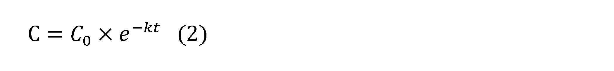
[2.3 Well-formed formula]
It is assumed that the attenuation of the residual chlorine concentration at the outlet with respect to the residual chlorine concentration at the condenser inlet can be explained by the primary reaction equation. Here, assuming that the residual chlorine concentration at the outlet is C, the residual chlorine concentration at the condenser inlet is C 0 , the reaction rate constant is k, and the flow time is t, the following formula (1) holds, and the formula (1) is established. Formula (2) is derived from.
復水器入口での残留塩素濃度に対する放水口での残留塩素濃度の減衰は、一次反応式で説明できると仮定する。ここで、放水口における残留塩素濃度をC、復水器入口における残留塩素濃度をC0、反応速度定数をk、流下時間をtとすると、以下の数式(1)が成り立ち、数式(1)から数式(2)が導かれる。
It is assumed that the attenuation of the residual chlorine concentration at the outlet with respect to the residual chlorine concentration at the condenser inlet can be explained by the primary reaction equation. Here, assuming that the residual chlorine concentration at the outlet is C, the residual chlorine concentration at the condenser inlet is C 0 , the reaction rate constant is k, and the flow time is t, the following formula (1) holds, and the formula (1) is established. Formula (2) is derived from.
更に反応速度定数kはArrheniusの式で説明され、以下の式に示す通り、水温上昇に伴い増加する。
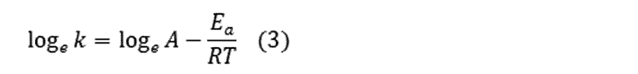
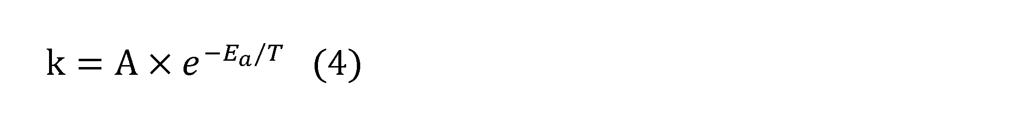
ここで、Aは定数である。Eaは海水への塩素注入の結果生成される次亜塩素酸イオン、次亜臭素酸イオン等と海水の成分との反応に固有の活性化エネルギーであり、例えば発電所の場所や時間により固有の定数である。また、Rは気体定数、Tは復水器出口での水温(K)である。
Furthermore, the reaction rate constant k is explained by the Arrhenius equation, and increases as the water temperature rises, as shown in the following equation.
Here, A is a constant. Specific E a is hypochlorite ions generated as a result of the chlorine injection into seawater, the reaction with hypobromite ions and seawater ingredients are intrinsic activation energy, for example, by location and time of the plant Is a constant of. Further, R is the gas constant, and T is the water temperature (K) at the outlet of the condenser.
ここでEa/Rを定数Bと置き換えると、

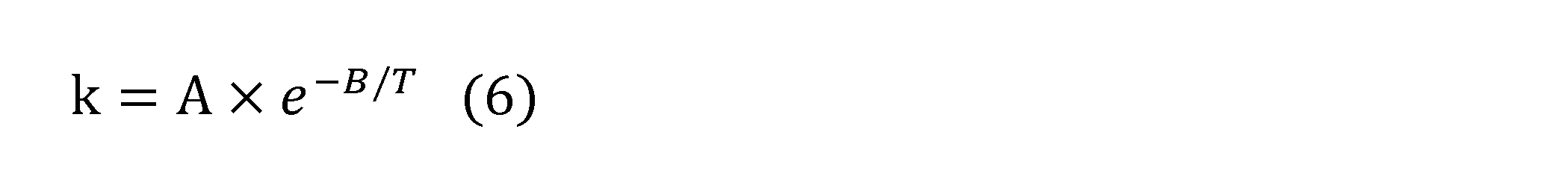
となる。すなわち、A、Bは定数であるので、水温Tから反応速度定数kを算出することができ、復水器入口における残留塩素濃度から放水口における残留塩素濃度を予測することができる。
If E a / R is replaced with the constant B here,
Will be. That is, since A and B are constants, the reaction rate constant k can be calculated from the water temperature T, and the residual chlorine concentration at the outlet can be predicted from the residual chlorine concentration at the condenser inlet.
具体的な予測方法としては、第1のステップとして、数式(2)に、過去の復水器入口の残留塩素濃度と放水口での残留塩素濃度と、少なくとも二組の実測値を代入し、複数の反応速度定数kを算出する。ここで、放水口での残留塩素濃度としては、数式(2)に代入した復水器入口での残留塩素濃度から所定時間(例えば4分間)静置した後の残留塩素濃度を用いてもよい。
As a specific prediction method, as the first step, the residual chlorine concentration at the inlet of the condenser and the residual chlorine concentration at the outlet are substituted into the mathematical formula (2), and at least two sets of actually measured values are substituted. A plurality of reaction rate constants k are calculated. Here, as the residual chlorine concentration at the outlet, the residual chlorine concentration after being allowed to stand for a predetermined time (for example, 4 minutes) from the residual chlorine concentration at the condenser inlet substituted in the formula (2) may be used. ..
第2のステップとして、第1のステップで得られた複数のkと、各kに対応する実測時の復水器出口または放水口水温を数式(6)に代入し、A、Bをそれぞれ算出する。
As the second step, the plurality of ks obtained in the first step and the condenser outlet or outlet water temperature at the time of actual measurement corresponding to each k are substituted into the formula (6), and A and B are calculated respectively. To do.
第3のステップとして、第2のステップで得られた係数A、Bと、現在の復水器出口または放水口の水温とを数式(6)に代入して、反応速度定数kを算出する。
As the third step, the coefficients A and B obtained in the second step and the water temperature at the current condenser outlet or outlet are substituted into the mathematical formula (6) to calculate the reaction rate constant k.
第4のステップとして、反応速度定数kと、復水器入口の残留塩素濃度とを用いて、放水口における残留塩素濃度を予測する。
As the fourth step, the reaction rate constant k and the residual chlorine concentration at the condenser inlet are used to predict the residual chlorine concentration at the outlet.
〔3 効果〕
上記実施形態に係る塩素注入濃度管理装置によれば、以下の効果が奏される。 [3 effects]
According to the chlorine injection concentration control device according to the above embodiment, the following effects are achieved.
上記実施形態に係る塩素注入濃度管理装置によれば、以下の効果が奏される。 [3 effects]
According to the chlorine injection concentration control device according to the above embodiment, the following effects are achieved.
(1)上記のように、上記実施形態に係る塩素注入濃度管理装置は、海水利用プラントのための塩素注入濃度管理装置であって、海水利用プラントにおける塩素注入口から注入する塩素の注入率と、当該注入から所定時間後の、海水利用プラントに設置される復水器の入口における残留塩素濃度との組のデータを取得するデータ取得部111と、少なくとも二組の注入率と残留塩素濃度とのデータに基づいて、注入率と残留塩素濃度との関係を指数近似する関係演算部112と、残留塩素濃度の目標値を取得する目標濃度取得部113と、残留塩素濃度の目標値と、指数近似された関係とに基づいて、注入率の最適値を算出する最適塩素注入率算出部114と、を備える。
これにより、従来技術に比較して、煩雑な手続を必要とせずに、復水器入口での残留塩素濃度を目標値に合わせることが可能となる。 (1) As described above, the chlorine injection concentration control device according to the above embodiment is a chlorine injection concentration control device for a seawater utilization plant, and has a chlorine injection rate to be injected from a chlorine injection port in the seawater utilization plant. , Adata acquisition unit 111 that acquires a set of data of the residual chlorine concentration at the inlet of the water recovery device installed in the seawater utilization plant after a predetermined time from the injection, and at least two sets of the injection rate and the residual chlorine concentration. Based on the data of, the relation calculation unit 112 that exponentially approximates the relationship between the injection rate and the residual chlorine concentration, the target concentration acquisition unit 113 that acquires the target value of the residual chlorine concentration, the target value of the residual chlorine concentration, and the index. The optimum chlorine injection rate calculation unit 114 for calculating the optimum value of the injection rate based on the approximated relationship is provided.
This makes it possible to match the residual chlorine concentration at the condenser inlet to the target value without requiring complicated procedures as compared with the conventional technique.
これにより、従来技術に比較して、煩雑な手続を必要とせずに、復水器入口での残留塩素濃度を目標値に合わせることが可能となる。 (1) As described above, the chlorine injection concentration control device according to the above embodiment is a chlorine injection concentration control device for a seawater utilization plant, and has a chlorine injection rate to be injected from a chlorine injection port in the seawater utilization plant. , A
This makes it possible to match the residual chlorine concentration at the condenser inlet to the target value without requiring complicated procedures as compared with the conventional technique.
(2)上記のように、上記実施形態に係る塩素注入濃度管理装置は、復水器の入口において残留塩素濃度を連続的に測定し、前記残留塩素濃度の実測値を前記データ取得部に出力する残留塩素分析部12を更に備える。
これにより、塩素注入濃度管理装置のユーザは、手分析によらず自動的に、復水器入口における残留塩素濃度を測定することが可能となる。 (2) As described above, the chlorine injection concentration control device according to the above embodiment continuously measures the residual chlorine concentration at the inlet of the condenser, and outputs the measured value of the residual chlorine concentration to the data acquisition unit. The residualchlorine analysis unit 12 is further provided.
This allows the user of the chlorine injection concentration control device to automatically measure the residual chlorine concentration at the condenser inlet without manual analysis.
これにより、塩素注入濃度管理装置のユーザは、手分析によらず自動的に、復水器入口における残留塩素濃度を測定することが可能となる。 (2) As described above, the chlorine injection concentration control device according to the above embodiment continuously measures the residual chlorine concentration at the inlet of the condenser, and outputs the measured value of the residual chlorine concentration to the data acquisition unit. The residual
This allows the user of the chlorine injection concentration control device to automatically measure the residual chlorine concentration at the condenser inlet without manual analysis.
(3)上記のように、上記実施形態に係る塩素注入濃度管理装置は、残留塩素濃度の目標値と前記復水器の出口または放水口での水温とに基づいて、前記海水利用プラントに設置される放水口での残留塩素濃度の予測値を算出する予測値算出部を更に備える。
これにより、塩素注入濃度管理装置のユーザは、放水口での残留塩素濃度を環境保全協定値に維持するための最適な注入率を把握することが可能となる。 (3) As described above, the chlorine injection concentration control device according to the above embodiment is installed in the seawater utilization plant based on the target value of the residual chlorine concentration and the water temperature at the outlet or the discharge port of the condenser. It is further provided with a predicted value calculation unit for calculating a predicted value of the residual chlorine concentration at the outlet.
As a result, the user of the chlorine injection concentration control device can grasp the optimum injection rate for maintaining the residual chlorine concentration at the outlet at the environmental conservation agreement value.
(4)上記のように、上記実施形態に係る塩素注入濃度管理装置は、放水口での残留塩素濃度を連続的に測定する第二残留塩素分析部14と、第二残留塩素分析部14によって測定された残留塩素濃度と予測値との差分が所定値を超えた場合に警報を発報する警報部116と、を更に備える。
これにより、塩素注入濃度管理装置のユーザは、放水口での残留塩素濃度の予測値を実現するために最適な注入率で塩素を注入していながら、放水口での残留塩素の実測値と、当該予測値との間に一定以上のかい離がある場合に、このかい離を認識することが可能となる。かい離を認識した際は復水器入口目標値を見直す必要があることになる。 (4) As described above, in the chlorine injection concentration control device according to the above embodiment, the second residualchlorine analysis unit 14 and the second residual chlorine analysis unit 14 continuously measure the residual chlorine concentration at the outlet. Further provided is an alarm unit 116 that issues an alarm when the difference between the measured residual chlorine concentration and the predicted value exceeds a predetermined value.
As a result, the user of the chlorine injection concentration control device can inject chlorine at the optimum injection rate in order to realize the predicted value of the residual chlorine concentration at the outlet, while measuring the measured value of the residual chlorine at the outlet. When there is a deviation of a certain amount or more from the predicted value, this deviation can be recognized. When the separation is recognized, it is necessary to review the condenser inlet target value.
これにより、塩素注入濃度管理装置のユーザは、放水口での残留塩素濃度の予測値を実現するために最適な注入率で塩素を注入していながら、放水口での残留塩素の実測値と、当該予測値との間に一定以上のかい離がある場合に、このかい離を認識することが可能となる。かい離を認識した際は復水器入口目標値を見直す必要があることになる。 (4) As described above, in the chlorine injection concentration control device according to the above embodiment, the second residual
As a result, the user of the chlorine injection concentration control device can inject chlorine at the optimum injection rate in order to realize the predicted value of the residual chlorine concentration at the outlet, while measuring the measured value of the residual chlorine at the outlet. When there is a deviation of a certain amount or more from the predicted value, this deviation can be recognized. When the separation is recognized, it is necessary to review the condenser inlet target value.
〔4 変形例〕
上述した実施形態は、本発明の好適な実施形態ではあるが、上記実施形態に本発明の範囲を限定するものではなく、本発明の要旨を逸脱しない範囲において、種々の変更を施した形態での実施が可能である。 [4 Modification example]
Although the above-described embodiment is a preferred embodiment of the present invention, the scope of the present invention is not limited to the above-described embodiment, and various modifications are made without departing from the gist of the present invention. Can be implemented.
〔4.1 変形例1〕
第1実施形態に係る塩素注入濃度管理装置1は残留塩素分析部12を備え、第2実施形態に係る塩素注入濃度管理装置1Aは、更に第二残留塩素分析部14を備えるとしたが、これには限定されない。例えば、残留塩素分析部12及び/又は第二残留塩素分析部14を必須の構成要素とせず、その代わりに、塩素注入濃度管理装置1又は1Aのユーザは、例えば手分析で測定された残留塩素濃度を、塩素注入濃度管理装置1又は1Aに対して手入力してもよい。 [4.1 Modification Example 1]
The chlorine injectionconcentration control device 1 according to the first embodiment includes a residual chlorine analysis unit 12, and the chlorine injection concentration control device 1A according to the second embodiment further includes a second residual chlorine analysis unit 14. Not limited to. For example, the residual chlorine analysis unit 12 and / or the second residual chlorine analysis unit 14 is not an essential component, and instead, the user of the chlorine injection concentration control device 1 or 1A can use the residual chlorine measured, for example, by hand analysis. The concentration may be manually entered for the chlorine injection concentration control device 1 or 1A.
第1実施形態に係る塩素注入濃度管理装置1は残留塩素分析部12を備え、第2実施形態に係る塩素注入濃度管理装置1Aは、更に第二残留塩素分析部14を備えるとしたが、これには限定されない。例えば、残留塩素分析部12及び/又は第二残留塩素分析部14を必須の構成要素とせず、その代わりに、塩素注入濃度管理装置1又は1Aのユーザは、例えば手分析で測定された残留塩素濃度を、塩素注入濃度管理装置1又は1Aに対して手入力してもよい。 [4.1 Modification Example 1]
The chlorine injection
〔4.2 変形例2〕
第1実施形態に係る塩素注入濃度管理装置1及び第2実施形態に係る塩素注入濃度管理装置1Aの関係演算部112は、少なくとも二組の、塩素の注入率と復水器の入口における残留塩素濃度との組のデータに基づいて、塩素の注入率と復水器の入口における残留塩素濃度との関係を指数近似するとしたがこれには限定されない。例えば、関係演算部112は、一組の塩素の注入率と復水器の入口における残留塩素濃度との組のデータと、ゼロ点、すなわち注入率と残留塩素濃度との双方がゼロのデータ、あるいは、注入率がゼロで、残留塩素濃度が所定値(例えば0.01mg/L)のデータを用いて、上記の関係を指数近似してもよい。 [4.2 Deformation Example 2]
Therelational calculation unit 112 of the chlorine injection concentration control device 1 according to the first embodiment and the chlorine injection concentration control device 1A according to the second embodiment has at least two sets of the chlorine injection rate and the residual chlorine at the inlet of the condenser. Based on the set of data with the concentration, the relationship between the chlorine injection rate and the residual chlorine concentration at the inlet of the condenser is exponentially approximated, but the relationship is not limited to this. For example, the relational calculus unit 112 has a set of data of a set of chlorine injection rates and a residual chlorine concentration at the inlet of the water recovery device, and a zero point, that is, data in which both the injection rate and the residual chlorine concentration are zero. Alternatively, the above relationship may be exponentially approximated using data in which the injection rate is zero and the residual chlorine concentration is a predetermined value (for example, 0.01 mg / L).
第1実施形態に係る塩素注入濃度管理装置1及び第2実施形態に係る塩素注入濃度管理装置1Aの関係演算部112は、少なくとも二組の、塩素の注入率と復水器の入口における残留塩素濃度との組のデータに基づいて、塩素の注入率と復水器の入口における残留塩素濃度との関係を指数近似するとしたがこれには限定されない。例えば、関係演算部112は、一組の塩素の注入率と復水器の入口における残留塩素濃度との組のデータと、ゼロ点、すなわち注入率と残留塩素濃度との双方がゼロのデータ、あるいは、注入率がゼロで、残留塩素濃度が所定値(例えば0.01mg/L)のデータを用いて、上記の関係を指数近似してもよい。 [4.2 Deformation Example 2]
The
塩素注入濃度管理装置1又は1Aによる管理方法は、ソフトウェアにより実現される。ソフトウェアによって実現される場合には、このソフトウェアを構成するプログラムが、コンピュータ(塩素注入濃度管理装置1又は1A)にインストールされる。また、これらのプログラムは、リムーバブルメディアに記録されてユーザに配布されてもよいし、ネットワークを介してユーザのコンピュータにダウンロードされることにより配布されてもよい。更に、これらのプログラムは、ダウンロードされることなくネットワークを介したWebサービスとしてユーザのコンピュータ(塩素注入濃度管理装置1又は1A)に提供されてもよい。
The management method by the chlorine injection concentration control device 1 or 1A is realized by software. When implemented by software, the programs that make up this software are installed in a computer (chlorine injection concentration control device 1 or 1A). In addition, these programs may be recorded on removable media and distributed to users, or may be distributed by being downloaded to a user's computer via a network. Further, these programs may be provided to the user's computer (chlorine injection concentration control device 1 or 1A) as a Web service via the network without being downloaded.
1 1A 塩素注入濃度管理装置
11 11A 制御部
12 残留塩素分析部
13 記憶部
14 第二残留塩素分析部
15 警報部
111 データ取得部
112 関係演算部
113 目標濃度取得部
114 最適塩素注入率算出部
115 予測値算出部 1 1A Chlorine injectionconcentration control device 11 11A Control unit 12 Residual chlorine analysis unit 13 Storage unit 14 Second residual chlorine analysis unit 15 Alarm unit 111 Data acquisition unit 112 Relationship calculation unit 113 Target concentration acquisition unit 114 Optimal chlorine injection rate calculation unit 115 Predicted value calculation unit
11 11A 制御部
12 残留塩素分析部
13 記憶部
14 第二残留塩素分析部
15 警報部
111 データ取得部
112 関係演算部
113 目標濃度取得部
114 最適塩素注入率算出部
115 予測値算出部 1 1A Chlorine injection
Claims (6)
- 海水利用プラントのための塩素注入濃度管理装置であって、
前記海水利用プラントにおける塩素注入口から注入する塩素(次亜塩素酸ソーダ)の注入率と、前記注入から所定時間後の、前記海水利用プラントに設置される復水器の入口における残留塩素濃度との組のデータを取得するデータ取得部と、
少なくとも二組の前記注入率と前記残留塩素濃度とのデータに基づいて、前記注入率と前記残留塩素濃度との関係を指数近似する関係演算部と、
前記残留塩素濃度の目標値を取得する目標濃度取得部と、
前記残留塩素濃度の目標値と、指数近似された前記関係とに基づいて、前記注入率の最適値を算出する最適塩素注入率算出部と、
を備える、塩素注入濃度管理装置。 A chlorine injection concentration control device for seawater utilization plants
The injection rate of chlorine (sodium hypochlorite) injected from the chlorine inlet of the seawater utilization plant and the residual chlorine concentration at the inlet of the condenser installed in the seawater utilization plant after a predetermined time from the injection. Data acquisition unit that acquires the set of data, and
A relational calculation unit that approximately approximates the relationship between the injection rate and the residual chlorine concentration based on at least two sets of data of the injection rate and the residual chlorine concentration.
A target concentration acquisition unit for acquiring the target value of the residual chlorine concentration, and a target concentration acquisition unit.
An optimum chlorine injection rate calculation unit that calculates the optimum value of the injection rate based on the target value of the residual chlorine concentration and the exponentially approximated relationship.
A chlorine injection concentration control device. - 前記復水器の入口において前記残留塩素濃度を連続的に測定し、前記残留塩素濃度の実測値を前記データ取得部に出力する残留塩素分析部を更に備える、請求項1に記載の塩素注入濃度管理装置。 The chlorine injection concentration according to claim 1, further comprising a residual chlorine analysis unit that continuously measures the residual chlorine concentration at the inlet of the condenser and outputs the measured value of the residual chlorine concentration to the data acquisition unit. Management device.
- 前記残留塩素濃度の目標値と前記復水器の出口または放水口の水温とに基づいて、前記海水利用プラントに設置される放水口での残留塩素濃度の予測値を算出する予測値算出部を更に備える、請求項1又は2に記載の塩素注入濃度管理装置。 Based on the target value of the residual chlorine concentration and the water temperature at the outlet or the discharge port of the condenser, a predictive value calculation unit that calculates the predicted value of the residual chlorine concentration at the discharge port installed in the seawater utilization plant is provided. The chlorine injection concentration control device according to claim 1 or 2, further provided.
- 前記放水口での残留塩素濃度を連続的に測定する第二残留塩素分析部と、
前記第二残留塩素分析部によって測定された前記残留塩素濃度と、前記予測値との差分が所定値を超えた場合に警報を発報する警報部と、
を更に備える、請求項3に記載の塩素注入濃度管理装置。 A second residual chlorine analyzer that continuously measures the residual chlorine concentration at the outlet,
An alarm unit that issues an alarm when the difference between the residual chlorine concentration measured by the second residual chlorine analysis unit and the predicted value exceeds a predetermined value.
The chlorine injection concentration control device according to claim 3, further comprising. - 海水利用プラントのための塩素注入濃度管理方法であって、
前記海水利用プラントにおける塩素注入口から注入する塩素の注入率と、前記注入から所定時間後の、前記海水利用プラントに設置される復水器の入口における残留塩素濃度との組のデータを取得するデータ取得ステップと、
少なくとも二組の前記注入率と前記残留塩素濃度とのデータに基づいて、前記注入率と前記残留塩素濃度との関係を指数近似する関係演算ステップと、
前記残留塩素濃度の目標値を取得する目標濃度取得ステップと、
前記残留塩素濃度の目標値と、指数近似された前記関係とに基づいて、前記注入率の最適値を算出する最適塩素注入率算出ステップと、
を有する、塩素注入濃度管理方法。 It is a chlorine injection concentration control method for seawater utilization plants.
Acquire a set of data of the injection rate of chlorine injected from the chlorine injection port in the seawater utilization plant and the residual chlorine concentration at the inlet of the condenser installed in the seawater utilization plant after a predetermined time from the injection. Data acquisition steps and
A relational calculation step for exponentially approximating the relationship between the injection rate and the residual chlorine concentration based on at least two sets of data of the injection rate and the residual chlorine concentration.
The target concentration acquisition step for acquiring the target value of the residual chlorine concentration and
An optimum chlorine injection rate calculation step for calculating the optimum value of the injection rate based on the target value of the residual chlorine concentration and the exponentially approximated relationship.
Chlorine injection concentration control method. - 海水利用プラントのための塩素注入濃度管理プログラムであって、
前記海水利用プラントにおける塩素注入口から注入する塩素の注入率と、前記注入から所定時間後の、前記海水利用プラントに設置される復水器の入口における残留塩素濃度との組のデータを取得するデータ取得ステップと、
少なくとも二組の前記注入率と前記残留塩素濃度とのデータに基づいて、前記注入率と前記残留塩素濃度との関係を指数近似する関係演算ステップと、
前記残留塩素濃度の目標値を取得する目標濃度取得ステップと、
前記残留塩素濃度の目標値と、指数近似された前記関係とに基づいて、前記注入率の最適値を算出する最適塩素注入率算出ステップと、
をコンピュータに実行させるための、塩素注入濃度管理プログラム。 A chlorine injection concentration control program for seawater utilization plants
Acquire a set of data of the injection rate of chlorine injected from the chlorine injection port in the seawater utilization plant and the residual chlorine concentration at the inlet of the condenser installed in the seawater utilization plant after a predetermined time from the injection. Data acquisition steps and
A relational calculation step for exponentially approximating the relationship between the injection rate and the residual chlorine concentration based on at least two sets of data of the injection rate and the residual chlorine concentration.
The target concentration acquisition step for acquiring the target value of the residual chlorine concentration and
An optimum chlorine injection rate calculation step for calculating the optimum value of the injection rate based on the target value of the residual chlorine concentration and the exponentially approximated relationship.
Chlorine injection concentration control program to let the computer run.
Priority Applications (3)
| Application Number | Priority Date | Filing Date | Title |
|---|---|---|---|
| JP2020502506A JP6730543B1 (en) | 2019-09-18 | 2019-09-18 | Chlorine injection concentration control device, chlorine injection concentration control method, and chlorine injection concentration control program |
| PCT/JP2019/036573 WO2021053757A1 (en) | 2019-09-18 | 2019-09-18 | Chlorine injection concentration management device, chlorine injection concentration management method, and chlorine injection concentration management program |
| TW109132054A TWI839572B (en) | 2019-09-18 | 2020-09-17 | Chlorine injection concentration management device, chlorine injection concentration management method, and chlorine injection concentration management program |
Applications Claiming Priority (1)
| Application Number | Priority Date | Filing Date | Title |
|---|---|---|---|
| PCT/JP2019/036573 WO2021053757A1 (en) | 2019-09-18 | 2019-09-18 | Chlorine injection concentration management device, chlorine injection concentration management method, and chlorine injection concentration management program |
Publications (1)
| Publication Number | Publication Date |
|---|---|
| WO2021053757A1 true WO2021053757A1 (en) | 2021-03-25 |
Family
ID=71738475
Family Applications (1)
| Application Number | Title | Priority Date | Filing Date |
|---|---|---|---|
| PCT/JP2019/036573 WO2021053757A1 (en) | 2019-09-18 | 2019-09-18 | Chlorine injection concentration management device, chlorine injection concentration management method, and chlorine injection concentration management program |
Country Status (2)
| Country | Link |
|---|---|
| JP (1) | JP6730543B1 (en) |
| WO (1) | WO2021053757A1 (en) |
Cited By (1)
| Publication number | Priority date | Publication date | Assignee | Title |
|---|---|---|---|---|
| JP7101912B1 (en) * | 2021-03-31 | 2022-07-15 | 中国電力株式会社 | Water quality management equipment, water quality management methods, and water quality management programs |
Citations (3)
| Publication number | Priority date | Publication date | Assignee | Title |
|---|---|---|---|---|
| JP2005144213A (en) * | 2003-11-11 | 2005-06-09 | Chugoku Electric Power Co Inc:The | Method and system for controlling adhesion and growth of marine organism |
| WO2008041470A1 (en) * | 2006-09-27 | 2008-04-10 | Tg Corporation | Method for treatment of ballast water for ship |
| JP2013186111A (en) * | 2012-03-12 | 2013-09-19 | Chugoku Electric Power Co Inc:The | Residual chlorine concentration analyser and method |
-
2019
- 2019-09-18 JP JP2020502506A patent/JP6730543B1/en active Active
- 2019-09-18 WO PCT/JP2019/036573 patent/WO2021053757A1/en active Application Filing
Patent Citations (3)
| Publication number | Priority date | Publication date | Assignee | Title |
|---|---|---|---|---|
| JP2005144213A (en) * | 2003-11-11 | 2005-06-09 | Chugoku Electric Power Co Inc:The | Method and system for controlling adhesion and growth of marine organism |
| WO2008041470A1 (en) * | 2006-09-27 | 2008-04-10 | Tg Corporation | Method for treatment of ballast water for ship |
| JP2013186111A (en) * | 2012-03-12 | 2013-09-19 | Chugoku Electric Power Co Inc:The | Residual chlorine concentration analyser and method |
Cited By (2)
| Publication number | Priority date | Publication date | Assignee | Title |
|---|---|---|---|---|
| JP7101912B1 (en) * | 2021-03-31 | 2022-07-15 | 中国電力株式会社 | Water quality management equipment, water quality management methods, and water quality management programs |
| WO2022208799A1 (en) * | 2021-03-31 | 2022-10-06 | 中国電力株式会社 | Water quality management device, water quality management method, and water quality management program |
Also Published As
| Publication number | Publication date |
|---|---|
| JP6730543B1 (en) | 2020-07-29 |
| JPWO2021053757A1 (en) | 2021-09-30 |
| TW202117559A (en) | 2021-05-01 |
Similar Documents
| Publication | Publication Date | Title |
|---|---|---|
| RU2533820C2 (en) | Method reducing corrosion and deposition of corrosion products in crude oil refining unit | |
| US8918217B2 (en) | Method and system for optimizing membrane cleaning process | |
| CN102807301B (en) | Outlet water quality online monitoring and real-time forecasting system of water reclamation plant and control method thereof | |
| JP2016507113A5 (en) | System and method for determining characteristics of a product or process stream | |
| KR101133664B1 (en) | Prediction, evaluation and control method of chemical cleaning of membrane process using genetic algorithm and programming in water treatment system | |
| JP4746385B2 (en) | Flocculant injection control device applied to water treatment plant | |
| JP4366244B2 (en) | Flocculant injection control system and alkaline agent injection control system for water purification plant | |
| FI126240B (en) | Method and device for monitoring and controlling the state of a process | |
| WO2021053757A1 (en) | Chlorine injection concentration management device, chlorine injection concentration management method, and chlorine injection concentration management program | |
| JP5019197B2 (en) | Water distribution information management device | |
| CN105540801B (en) | Fluorine-contained wastewater treatment system and method | |
| US20050137995A1 (en) | Method for regulating a thermodynamic process by means of neural networks | |
| JP4145717B2 (en) | Water quality monitoring and control system | |
| JP2008194559A (en) | Apparatus for controlling injection of flocculant | |
| CN112014344B (en) | Online sewage monitoring method | |
| JP7264697B2 (en) | Plant operation support system and plant operation support method | |
| JP7000063B2 (en) | Cleaning air volume control device and cleaning air volume control method | |
| CN114323120B (en) | Sludge discharge amount measuring method, control method, treatment system, equipment and medium | |
| JP3969217B2 (en) | Disinfection by-product concentration control method and apparatus | |
| JP7106438B2 (en) | Water quality measurement system and maintenance method determination method | |
| WO2022208799A1 (en) | Water quality management device, water quality management method, and water quality management program | |
| CN107679631B (en) | Maintenance scheme making method and operation management platform | |
| JPH05309376A (en) | Liquid neutralizing apparatus | |
| Goldman-Torres et al. | When the Model isn’t Enough: Peracetic Acid Dosing Recommendations in the Real World | |
| CN111985146B (en) | Method and device for determining measure potential well |
Legal Events
| Date | Code | Title | Description |
|---|---|---|---|
| ENP | Entry into the national phase |
Ref document number: 2020502506 Country of ref document: JP Kind code of ref document: A |
|
| 121 | Ep: the epo has been informed by wipo that ep was designated in this application |
Ref document number: 19945747 Country of ref document: EP Kind code of ref document: A1 |
|
| NENP | Non-entry into the national phase |
Ref country code: DE |
|
| 122 | Ep: pct application non-entry in european phase |
Ref document number: 19945747 Country of ref document: EP Kind code of ref document: A1 |