WO2021049367A1 - 通信制御方法 - Google Patents
通信制御方法 Download PDFInfo
- Publication number
- WO2021049367A1 WO2021049367A1 PCT/JP2020/033008 JP2020033008W WO2021049367A1 WO 2021049367 A1 WO2021049367 A1 WO 2021049367A1 JP 2020033008 W JP2020033008 W JP 2020033008W WO 2021049367 A1 WO2021049367 A1 WO 2021049367A1
- Authority
- WO
- WIPO (PCT)
- Prior art keywords
- data
- rrc
- information
- control method
- user device
- Prior art date
- Legal status (The legal status is an assumption and is not a legal conclusion. Google has not performed a legal analysis and makes no representation as to the accuracy of the status listed.)
- Ceased
Links
Images


Classifications
-
- H—ELECTRICITY
- H04—ELECTRIC COMMUNICATION TECHNIQUE
- H04W—WIRELESS COMMUNICATION NETWORKS
- H04W76/00—Connection management
-
- H—ELECTRICITY
- H04—ELECTRIC COMMUNICATION TECHNIQUE
- H04W—WIRELESS COMMUNICATION NETWORKS
- H04W74/00—Wireless channel access
- H04W74/08—Non-scheduled access, e.g. ALOHA
- H04W74/0833—Random access procedures, e.g. with 4-step access
-
- H—ELECTRICITY
- H04—ELECTRIC COMMUNICATION TECHNIQUE
- H04W—WIRELESS COMMUNICATION NETWORKS
- H04W76/00—Connection management
- H04W76/20—Manipulation of established connections
- H04W76/27—Transitions between radio resource control [RRC] states
-
- Y—GENERAL TAGGING OF NEW TECHNOLOGICAL DEVELOPMENTS; GENERAL TAGGING OF CROSS-SECTIONAL TECHNOLOGIES SPANNING OVER SEVERAL SECTIONS OF THE IPC; TECHNICAL SUBJECTS COVERED BY FORMER USPC CROSS-REFERENCE ART COLLECTIONS [XRACs] AND DIGESTS
- Y02—TECHNOLOGIES OR APPLICATIONS FOR MITIGATION OR ADAPTATION AGAINST CLIMATE CHANGE
- Y02D—CLIMATE CHANGE MITIGATION TECHNOLOGIES IN INFORMATION AND COMMUNICATION TECHNOLOGIES [ICT], I.E. INFORMATION AND COMMUNICATION TECHNOLOGIES AIMING AT THE REDUCTION OF THEIR OWN ENERGY USE
- Y02D30/00—Reducing energy consumption in communication networks
- Y02D30/70—Reducing energy consumption in communication networks in wireless communication networks
Definitions
- the present disclosure relates to a communication control method used in a mobile communication system.
- the 3GPP (Third Generation Partnership Project) standard, which is a standardization project for mobile communication systems, defines early data transmission (EDT) for transmitting uplink data during a random access procedure (see, for example, Non-Patent Document 1). .. In EDT, downlink data transmission following uplink data transmission is also possible during a random access procedure.
- the user device that performs LPWA communication has a small amount of data to be transmitted and received, and the frequency of transmitting and receiving data is also low.
- EDT can be applied not only to a user device that performs such LPWA communication but also to a user device such as a smartphone.
- the communication control method is a method for controlling specific data transmission in which a user device transmits or receives data of a predetermined size or less during a random access procedure.
- the communication control method provides auxiliary information for the base station to determine whether or not the user device in the RRC connected state sets the data transmission setting necessary for performing the specific data transmission to the user device.
- an RRC release message including setting information indicating the data transmission setting is sent. It has to transmit to a user device.
- the communication control method is a method for controlling specific data transmission in which a user device transmits or receives data of a predetermined size or less set from a base station during a random access procedure.
- the communication control method each time the user device in the RRC idle state or the RRC inactive state generates data to be transmitted to the network, the generated data is stored and the size of the generated data is stored. That is, the user device that has transitioned to the RRC connected state transmits information indicating the size of each of the generated data to the network.
- the mobile communication system according to one embodiment is a 5G system of 3GPP, but LTE (Long Term Evolution) may be applied to the mobile communication system at least partially.
- LTE Long Term Evolution
- FIG. 1 is a diagram showing a configuration of a mobile communication system according to an embodiment.
- mobile communication systems include a user device (UE: User Equipment) 100, a 5G radio access network (NG-RAN: Next Generation Radio Access Network) 10, and a 5G core network (5GC: 5G). It has Core Network) 20.
- UE User Equipment
- NG-RAN Next Generation Radio Access Network
- 5GC 5G core network
- the UE100 is a movable device.
- the UE 100 may be any device as long as it is a device used by the user.
- the UE 100 is a mobile phone terminal (including a smartphone), a tablet terminal, a notebook PC, a communication module (including a communication card or a chipset), a sensor or a device provided in the sensor, a vehicle or a device provided in the vehicle (Vehicle UE). ) And / or a vehicle or a device (Aerial UE) provided on the vehicle.
- the NG-RAN 10 includes a base station (called "gNB” in a 5G system) 200.
- the gNB 200 is sometimes referred to as an NG-RAN node.
- the gNB 200s are connected to each other via the Xn interface, which is an interface between base stations.
- the gNB 200 manages one or more cells.
- the gNB 200 performs wireless communication with the UE 100 that has established a connection with its own cell.
- the gNB 200 has a radio resource management (RRM) function, a routing function for user data (hereinafter, simply referred to as “data”), a measurement control function for mobility control / scheduling, and the like.
- RRM radio resource management
- Cell is used as a term to indicate the smallest unit of a wireless communication area.
- the term “cell” is also used to indicate a function or resource for wireless communication with the UE 100.
- One cell belongs to one carrier frequency.
- the gNB may be connected to the LTE core network EPC (Evolved Packet Core), or the LTE base station may be connected to the 5GC. Further, the LTE base station and the gNB may be connected via the inter-base station interface.
- EPC Evolved Packet Core
- 5GC20 includes AMF (Access and Mobility Management Function) and UPF (User Plane Function) 300.
- the AMF performs various mobility controls and the like for the UE 100.
- the AMF manages information on the area in which the UE 100 is located by communicating with the UE 100 using NAS (Non-Access Stratum) signaling.
- UPF controls data transfer.
- the AMF and UPF are connected to the gNB 200 via the NG interface, which is a base station-core network interface.
- FIG. 2 is a diagram showing a configuration of a UE 100 (user device) according to an embodiment.
- the UE 100 includes a receiving unit 110, a transmitting unit 120, and a control unit 130.
- the transmission unit 120 performs various transmissions under the control of the control unit 130.
- the transmitter 120 includes an antenna and a transmitter.
- the transmitter converts the baseband signal (transmission signal) output by the control unit 130 into a radio signal and transmits it from the antenna.
- the control unit 130 performs various controls on the UE 100.
- the control unit 130 includes at least one processor and at least one memory electrically connected to the processor.
- the memory stores a program executed by the processor and information used for processing by the processor.
- the processor may include a baseband processor and a CPU (Central Processing Unit).
- the baseband processor modulates / demodulates and encodes / decodes the baseband signal.
- the CPU executes a program stored in the memory to perform various processes.
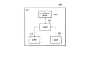
- FIG. 3 is a diagram showing the configuration of gNB200 (base station) according to one embodiment.
- the gNB 200 includes a transmission unit 210, a reception unit 220, a control unit 230, and a backhaul communication unit 240.
- the transmission unit 210 performs various transmissions under the control of the control unit 230.
- the transmitter 210 includes an antenna and a transmitter.
- the transmitter converts the baseband signal (transmission signal) output by the control unit 230 into a radio signal and transmits it from the antenna.
- the receiving unit 220 performs various receptions under the control of the control unit 230.
- the receiving unit 220 includes an antenna and a receiver.
- the receiver converts the radio signal received by the antenna into a baseband signal (received signal) and outputs it to the control unit 230.
- the control unit 230 performs various controls on the gNB 200.
- the control unit 230 includes at least one processor and at least one memory electrically connected to the processor.
- the memory stores a program executed by the processor and information used for processing by the processor.
- the processor may include a baseband processor and a CPU.
- the baseband processor modulates / demodulates and encodes / decodes the baseband signal.
- the CPU executes a program stored in the memory to perform various processes.
- the backhaul communication unit 240 is connected to an adjacent base station via an interface between base stations.
- the backhaul communication unit 240 is connected to the AMF / UPF 300 via the base station-core network interface.
- the gNB is composed of a CU (Central Unit) and a DU (Distributed Unit) (that is, the functions are divided), and both units may be connected by an F1 interface.
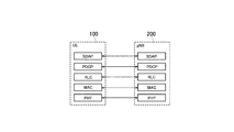
- FIG. 4 is a diagram showing a configuration of a protocol stack of a user plane wireless interface that handles data.
- the wireless interface protocol of the user plane includes a physical (PHY) layer, a MAC (Medium Access Control) layer, an RLC (Radio Link Control) layer, a PDCP (Packet Data Convergence Protocol) layer, and the like. It has an SDAP (Service Data Application Protocol) layer.
- PHY physical
- MAC Medium Access Control
- RLC Radio Link Control
- PDCP Packet Data Convergence Protocol
- SDAP Service Data Application Protocol
- the PHY layer performs coding / decoding, modulation / demodulation, antenna mapping / demapping, and resource mapping / demapping. Data and control information are transmitted between the PHY layer of the UE 100 and the PHY layer of the gNB 200 via a physical channel.
- the RLC layer transmits data to the receiving RLC layer by using the functions of the MAC layer and the PHY layer. Data and control information are transmitted between the RLC layer of the UE 100 and the RLC layer of the gNB 200 via a logical channel.
- the SDAP layer maps the IP flow, which is a unit for performing QoS control by the core network, with the wireless bearer, which is a unit for performing QoS control by AS (Access Stratum).
- AS Access Stratum
- FIG. 5 is a diagram showing a configuration of a protocol stack of a wireless interface of a control plane that handles signaling (control signal).
- the protocol stack of the radio interface of the control plane has an RRC (Radio Resource Control) layer and a NAS (Non-Access Stratum) layer in place of the SDAP layer shown in FIG.
- RRC signaling for various settings is transmitted between the RRC layer of UE100 and the RRC layer of gNB200.
- the RRC layer controls logical channels, transport channels, and physical channels in response to the establishment, reestablishment, and release of radio bearers.
- RRC connection connection between the RRC of the UE 100 and the RRC of the gNB 200
- the UE 100 is in the RRC connected state.
- RRC connection no connection between the RRC of the UE 100 and the RRC of the gNB 200
- the UE 100 is in the RRC idle state. Further, when the RRC connection is suspended, the UE 100 is in the RRC inactive state.
- the NAS layer located above the RRC layer performs session management, mobility management, etc.
- NAS signaling is transmitted between the NAS layer of the UE 100 and the NAS layer of the AMF 300.
- the UE 100 has an application layer and the like in addition to the wireless interface protocol.
- EDT sends uplink data during a random access procedure. Further, in the EDT, it is possible to transmit the downlink data following the uplink data transmission during the random access procedure.
- the EDT Is started.
- the EDT includes an uplink EDT that sends and receives uplink data using Msg3 in a random access procedure, and a downlink EDT that sends and receives downlink data using Msg4 in a random access procedure.
- an uplink EDT that sends and receives uplink data using Msg3 in a random access procedure
- a downlink EDT that sends and receives downlink data using Msg4 in a random access procedure.
- only the uplink EDT may be performed, or both the uplink EDT and the downlink EDT may be performed.
- only uplink EDT may be done.
- EDT EDT
- UP User Plane
- CP Control Plane
- UP User Plane
- CP Control Plane
- the user data DTCH
- CCCH RRC message
- the CP solution the user data is included in the RRC message in the EDT.
- the UP solution is applicable when the UE 100 is in the RRC inactive state.
- the context information of the UE 100 is maintained in the gNB 200.
- the RRC message constituting Msg3 is an RRC Request Request message
- the RRC message constituting Msg4 is basically an RRC Release message (RRC release message).
- RRC release message When the UE 100 receives the RRC Release message, the UE 100 terminates the random access procedure while maintaining the RRC idle state.
- the RRC message constituting Msg4 may be an RRC Resumé message.
- the UE 100 receives the RRC Resume message, it transitions to the RRC connected state and transmits / receives user data in the RRC connected state.
- the CP solution is applicable when the UE 100 is in the RRC idle state.
- the RRC message constituting Msg3 is an RRC Early Data Request message
- the RRC message constituting Msg4 is an RRC Early Data Complete message.
- the RRC message constituting Msg4 may be an RRC Setup message.
- the UE 100 receives the RRC Setup message, it transitions to the RRC connected state and transmits / receives user data in the RRC connected state.
- the UP solution of EDT is mainly assumed, but the CP solution may be assumed as well as the UP solution.
- the gNB 200 in order for the UE 100 to perform the EDT, the gNB 200 needs to set the EDT on the UE 100 in advance. For example, an RRC release message including setting information (drb-ContinueROHC) indicating whether or not header compression is executed (continued) at the time of EDT and setting information (nextHopChainingCount) for updating the security key (KeNB) is sent from gNB200 to UE100. Must be sent.
- LTE EDT is applied only to UE100 that performs LPWA communication.
- a UE 100 has a small amount of data to be transmitted / received, and the frequency of transmitting / receiving data is also small. Therefore, it is considered that the size of the uplink data transmitted by the UE 100 by the EDT is generally equal to or less than the maximum data size set in the system information. Therefore, it is easy to determine whether or not the gNB 200 sets the EDT in the UE 100.
- the EDT can be applied not only to the UE 100 that performs LPWA communication but also to the UE 100 such as a smartphone
- the traffic pattern of the UE 100 particularly whether or not the data at the time of EDT transmission is a small amount of data (small packet) is determined. It is difficult for the gNB 200 to grasp. Therefore, it is difficult to determine whether or not the gNB 200 sets the EDT in the UE 100.
- auxiliary information from the UE 100 to the gNB 200, it is facilitated to determine whether or not the gNB 200 sets the EDT in the UE 100.
- the communication control method is a method for the UE 100 to control an EDT that transmits or receives data of a predetermined size or less during a random access procedure.
- the predetermined size means the maximum data size set by the system information, but the maximum data size may be set by the signaling (dedicated signaling) for each UE 100, and the maximum data size is predetermined by the specifications. May be.
- the predetermined size means the maximum data size of the uplink data, but may be the maximum data size of the downlink data.
- the maximum data size may be expressed in terms of transport block size (TBS).
- the UE 100 in the RRC connected state assists the gNB 200 in determining whether or not the UE 100 is provided with the data transmission setting (that is, the EDT setting) necessary for performing the EDT.
- Information (hereinafter referred to as "EDT auxiliary information”) is transmitted to gNB200.
- the gNB 200 determines that the EDT setting is performed on the UE 100 based on the EDT auxiliary information
- the gNB 200 transmits an RRC release message including the setting information indicating the EDT setting (hereinafter, referred to as “EDT setting information”) to the UE 100.
- EDT setting information the setting information indicating the EDT setting
- step S101 the UE 100 is in the RRC connected state in the cell of the gNB 200.
- step S102 the UE 100 sends and receives data (user data) to and from the gNB 200.
- step S103 the UE 100 determines that there is no data to be transmitted / received to / from the gNB 200, or there is no data to be transmitted / received to / from the gNB 200, and sends an RRC message to the gNB 200 to prompt the gNB 200 to release or interrupt the RRC connection of the UE 100. Send to.
- Such an RRC message may be referred to as a RAI (Releasure Indication) message.
- the UE 100 includes the EDT auxiliary information for the gNB 200 to determine whether or not to perform the EDT setting necessary for performing the EDT in the RAI message.
- the EDT auxiliary information may include request information that requires the gNB 200 to perform the EDT setting.
- the UE 100 determines the size and / or generation pattern of data to be transmitted or received in the future, and determines whether or not to perform EDT based on the determined size and / or generation pattern.
- the data scheduled to be transmitted or received in the future refers to the data scheduled to be transmitted or received after the UE 100 transitions to the RRC idle state or the RRC inactive state.
- the data scheduled to be transmitted or received in the future may be data scheduled to be transmitted or received by the UE 100 next time, or may be data scheduled to be transmitted or received by the UE 100 one after another.
- the UE 100 predicts data to be transmitted or received in the future based on information obtained from, for example, an application layer.
- the UE 100 transmits the request information requesting the gNB 200 to perform the EDT setting to the gNB 200.
- the EDT auxiliary information may include data-related information regarding data that the UE 100 plans to transmit or receive in the future.
- the data-related information may include size information regarding the size of data that the UE 100 plans to transmit or receive in the future.
- the size information may be information indicating the transport block size of the data that the UE 100 plans to transmit or receive in the future.
- the size information may be an identifier indicating whether or not the transport block size of the data to be transmitted or received by the UE 100 in the future is equal to or less than a predetermined size.
- the UE 100 may transmit size information to the gNB 200 only when it is predicted that the data to be transmitted or received by the UE 100 in the future is single-shot data.
- single-shot data such as the data generation interval
- the conditions for "single-shot data" may be set from gNB200 to UE100.
- the data-related information may include time information regarding the generation pattern of data that the UE 100 plans to transmit or receive in the future.
- the time information may include information indicating whether or not the data to be transmitted or received by the UE 100 in the future is single-shot data.
- the time information may include information indicating an generation interval (generation cycle) of data scheduled to be transmitted or received by the UE 100 in the future.
- the time information may include information indicating the time of occurrence of data scheduled to be transmitted or received by the UE 100 in the future.
- the occurrence time may be a relative time (for example, after 30 seconds) or an absolute time (for example, (H ⁇ ) SFN number).
- the RAI message is not limited to the RRC message, and may be a MAC control element (MAC CE).
- This MAC CE may be for prompting the gNB 200 to release or interrupt the RRC connection of the UE 100.
- step S104 the gNB 200 determines whether or not to set the EDT in the UE 100 based on the EDT auxiliary information included in the RAI message received from the UE 100.
- the gNB 200 determines that the EDT setting is performed on the UE 100 will be described.
- the gNB 200 transmits an RRC release message including EDT setting information indicating the EDT setting to the UE 100.
- the EDT setting information includes at least one of the setting information (drb-ContinueROHC) indicating whether or not the header compression is executed (continued) at the time of EDT and the setting information (nextHopChainingCount) for updating the security key (KeNB).
- the gNB 200 When the gNB 200 transitions the UE 100 to the RRC inactive state, the gNB 200 includes the setting information (Suspend Config.) Of the RRC inactive state in the RRC release message. The gNB 200 uses Suspend Config. May be included in.
- the gNB 200 determines in step S104 that the EDT setting is not performed on the UE 100, the gNB 200 transmits an RRC release message that does not include the EDT setting information to the UE 100.
- step S106 the UE 100 stores the EDT setting information included in the RRC release message received from the gNB 200.
- the UE 100 determines whether or not the size of the uplink data generated in step S108 is equal to or less than the maximum data size indicated by the EDT maximum size information. If the size of the uplink data generated in step S108 is equal to or less than the maximum data size indicated by the EDT maximum size information, the UE 100 determines that the EDT can be applied, and otherwise determines that the EDT cannot be applied. In the following, the description will proceed on the assumption that the UE 100 determines that the EDT can be applied.
- Steps S110 to S113 constitute a random access procedure.
- the UE 100 transmits Msg1 (random access preamble) to the gNB 200.
- Msg random access preamble
- Msg is an abbreviation for a message.
- step S111 the gNB 200 transmits Msg2 (random access response) including scheduling information indicating the uplink radio resource assigned to the UE 100 to the UE 100.
- Msg2 random access response
- step S112 the UE 100 transmits Msg3 to the gNB 200 based on the scheduling information from the gNB 200.
- Msg3 is, for example, an RRC Request Request message.
- the UE 100 multiplexes the user data (DTCH) and the RRC Request Request message into one MAC PDU and transmits the user data (DTCH) in the MAC layer.
- uplink EDT is performed.
- the EDT setting information is applied to the transmission of user data (uplink data).
- the gNB 200 transmits Msg4 to the UE 100.
- Msg4 is an RRC Release message (RRC release message).
- the gNB 200 may transmit the downlink data by multiplexing it with the RRC Release message. As a result, downlink EDT is performed.
- the UE 100 Upon receiving the RRC Release message, the UE 100 terminates the random access procedure while maintaining the RRC idle state or the RRC inactive state.
- the EDT auxiliary information may be included in a message other than the RAI message (for example, RRC message or MAC CE).
- the UE 100 may include the EDT auxiliary information in any message as long as it is a message to be transmitted to the gNB 200 at a stage prior to receiving the RRC release message from the gNB 200.
- the gNB 200 sets the maximum data amount (maximum transport block size) in the EDT to the UE 100, it is difficult for the gNB 200 to determine the optimum maximum data amount. Specifically, the amount of data (transport block size) transmitted and received by the UE 100 by the EDT changes according to the type and situation of the application executed by the UE 100. If the maximum amount of data in the EDT is set too large, wasteful resources may occur. On the other hand, if the maximum data amount setting in the EDT is too small, the UE 100 that wants to send and receive data exceeding the maximum transport block size cannot use the EDT, so that the effects of power consumption reduction and delay reduction by the EDT are impaired.
- the UE 100 determines the amount of user data to be transmitted / received in the EDT. For example, the UE 100 determines the amount of uplink data that the UE 100 wants to transmit by the uplink EDT. In addition to or in place of such determination, the UE 100 may determine the amount of downlink data that the UE 100 wants to receive by downlink EDT. Then, when the UE 100 is in the RRC connected state, the UE 100 transmits information indicating the maximum data amount (maximum transport block size) recommended by the UE 100 to the gNB 200 based on the determined amount of user data. Such a recommended maximum data amount may be the recommended maximum data amount for the uplink or the recommended maximum data amount for the downlink.
- Notification of such a maximum amount of data may be performed only by the UE 100 having the ability to perform EDT.
- the gNB 200 may store the notification from the UE 100 in the UE context as UE capability information.
- the gNB 200 collects information on the recommended maximum data amount for EDT from a large number of UEs 100, and performs statistical processing on the collected information to determine the optimum maximum data amount in EDT. For example, the gNB 200 collects information on the recommended maximum amount of data for the uplink EDT, and based on the collected information, determines the optimum maximum amount of data for the uplink EDT. The gNB 200 may collect information on the recommended maximum amount of data for the downlink EDT, and based on the collected information, determine the optimum maximum amount of data for the downlink EDT. After determining the optimum maximum data amount, the gNB 200 sets the determined maximum data amount in the UE 100. For example, the gNB 200 sets the maximum data amount in the UE 100 in the cell of the gNB 200 by broadcasting information indicating the determined maximum data amount.
- FIG. 7 is a diagram showing the operation of the modification example 1.
- an example of notifying the gNB 200 of the recommended maximum uplink data amount in the EDT using Msg3 will be described.
- the following example is described using the recommended maximum uplink data amount as an example, it can also be applied by replacing it with the recommended maximum downlink data amount.
- step S201 the gNB 200 transmits information to the UE 100 that requests or sets the transmission of the notification of the recommended maximum uplink data amount in the EDT.
- the gNB 200 uses such information as Msg4 (RRC Connection Setup message) in a random access procedure, measurement setting (Measurement Connection) which is a unicast message, UE Information Request message and / or MDT (Minimation Message Setting) May be included in.
- Msg4 RRC Connection Setup message
- measurement setting Measurement Connection
- UE Information Request message a unicast message
- MDT Minimum Message Setting
- step S201 is not essential and can be omitted.
- step S202 the UE 100 determines the recommended maximum uplink data amount in the EDT. For example, the UE 100 stores the amount of uplink data when performing a random access procedure in response to the generation of uplink data, and determines the amount of stored uplink data as the recommended maximum uplink data amount. To do.
- the UE 100 transmits information indicating the determined recommended maximum uplink data amount to the gNB 200.
- the UE 100 may include such information in the measurement report, or may include it in the random access procedure Msg5 (RRC Connection Step Complete or RRC Connection Resume Complete) or the UE Information Response message or the UE Assistance Information message.
- the RRC Connection Setup Complete and the RRC Connection Resumé Complete may be positioned as messages transmitted from the UE 100 to the gNB 200 immediately after the random access procedure.
- step S204 the gNB 200 determines the optimum maximum uplink data amount based on the recommended maximum uplink data amount notified from the UE 100. After determining the optimum maximum uplink data amount, the gNB 200 sets the maximum uplink data amount in the UE 100 in the cell of the gNB 200 by broadcasting the determined maximum uplink data amount.
- the gNB 200 is not limited to the case where the maximum data amount (maximum uplink data amount) is set to the UE 100 by broadcasting, and the maximum data amount may be set to the UE 100 by unicast (for example, RRC Connection Release). In such a case, the gNB 200 determines the optimum maximum data amount for the UE 100 based on the recommended maximum data amount notified from the UE 100, and sets the determined maximum data amount in the UE 100 by unicast.
- the maximum data amount maximum uplink data amount
- the gNB 200 determines the optimum maximum data amount for the UE 100 based on the recommended maximum data amount notified from the UE 100, and sets the determined maximum data amount in the UE 100 by unicast.
- the gNB 200 can grasp the size of the data transmitted by the UE 100 after the RRC connection is established. However, when small packets are generated intermittently and the UE 100 transmits these plurality of small packets at once, the gNB 200 can only grasp the total packet size and cannot grasp the size of each packet. Therefore, in the second modification, the gNB 200 (network) can grasp the size of each data generated in the UE 100 in the RRC idle state or the RRC inactive state.
- the communication control method according to the second modification is a method for controlling the EDT in which the UE 100 transmits or receives data of a predetermined size or less set from the gNB 200 during the random access procedure.
- the UE 100 in the RRC idle state or the RRC inactive state stores the generated data and the size of the generated data each time data to be transmitted to the network is generated. ..
- the UE 100 that has transitioned to the RRC connected state transmits information indicating the size of each generated data (hereinafter, referred to as “data size information”) to the network.
- data size information information indicating the size of each generated data
- the network can grasp the size of each data generated in the UE 100 in the RRC idle state or the RRC inactive state. Then, the network can optimize the maximum uplink data amount of the EDT based on the size of each data grasped in the same manner as in the first modification.
- the UE 100 that has transitioned to the RRC connected state may further transmit the time information of each of the generated data to the network.
- the time information is information (time stamp information) indicating the time when the data is generated.
- the UE 100 that has transitioned to the RRC connected state may further transmit the position information of each of the generated data to the network.
- the position information is information indicating the position of the UE 100 at the time of data generation (for example, GNSS position information).
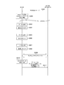
- FIG. 8 is a diagram showing the operation of the second modification.
- the UE 100 receives the RRC release message from the gNB 200.
- the RRC release message may include logging setting information that sets at least one storage (logging) of data size information, time information, and location information in the UE 100.
- step S302 the UE 100 transitions from the RRC connected state to the RRC idle state or the RRC inactive state in response to the RRC release message from the gNB 200.
- step S303 the UE 100 generates uplink data # 1 and stores the generated uplink data # 1.
- step S304 the UE 100 acquires data size information # 1, time information # 1, and position information # 1 for uplink data # 1, and stores the acquired information (logging).
- step S305 the UE 100 generates uplink data # 2 and stores the generated uplink data # 2.
- step S306 the UE 100 acquires data size information # 2, time information # 2, and position information # 2 for uplink data # 2, and stores the acquired information (logging).
- step S307 the UE 100 generates uplink data # 3 and stores the generated uplink data # 3.
- step S308 the UE 100 acquires data size information # 3, time information # 3, and position information # 3 for uplink data # 3, and stores the acquired information (logging).
- step S309 the UE 100 performs a random access procedure with gNB200.
- step S310 the UE 100 transitions to the RRC connected state.
- step S311 the UE 100 obtains the stored uplink data # 1 to # 3, the stored data size information # 1 to # 3, the stored time information # 1 to # 3, and the stored position information # 1 to # 3. Send to gNB200.
- a program that causes the computer to execute each process performed by the UE 100 or the gNB 200 may be provided.
- the program may be recorded on a computer-readable medium.
- Computer-readable media can be used to install programs on a computer.
- the computer-readable medium on which the program is recorded may be a non-transient recording medium.
- the non-transient recording medium is not particularly limited, but may be, for example, a recording medium such as a CD-ROM or a DVD-ROM.
- a circuit that executes each process performed by the UE 100 or the gNB 200 may be integrated, and at least a part of the UE 100 or the gNB 200 may be configured as a semiconductor integrated circuit (chipset, SoC).
Landscapes
- Engineering & Computer Science (AREA)
- Computer Networks & Wireless Communication (AREA)
- Signal Processing (AREA)
- Mobile Radio Communication Systems (AREA)
Priority Applications (3)
| Application Number | Priority Date | Filing Date | Title |
|---|---|---|---|
| EP20862517.8A EP4030866B1 (en) | 2019-09-13 | 2020-09-01 | Communication control method |
| JP2021545235A JP7229374B2 (ja) | 2019-09-13 | 2020-09-01 | 通信制御方法 |
| US17/654,492 US12309868B2 (en) | 2019-09-13 | 2022-03-11 | Communication control method |
Applications Claiming Priority (2)
| Application Number | Priority Date | Filing Date | Title |
|---|---|---|---|
| US201962899852P | 2019-09-13 | 2019-09-13 | |
| US62/899,852 | 2019-09-13 |
Related Child Applications (1)
| Application Number | Title | Priority Date | Filing Date |
|---|---|---|---|
| US17/654,492 Continuation US12309868B2 (en) | 2019-09-13 | 2022-03-11 | Communication control method |
Publications (1)
| Publication Number | Publication Date |
|---|---|
| WO2021049367A1 true WO2021049367A1 (ja) | 2021-03-18 |
Family
ID=74866098
Family Applications (1)
| Application Number | Title | Priority Date | Filing Date |
|---|---|---|---|
| PCT/JP2020/033008 Ceased WO2021049367A1 (ja) | 2019-09-13 | 2020-09-01 | 通信制御方法 |
Country Status (4)
| Country | Link |
|---|---|
| US (1) | US12309868B2 (https=) |
| EP (1) | EP4030866B1 (https=) |
| JP (1) | JP7229374B2 (https=) |
| WO (1) | WO2021049367A1 (https=) |
Cited By (4)
| Publication number | Priority date | Publication date | Assignee | Title |
|---|---|---|---|---|
| WO2022207355A1 (en) * | 2021-03-30 | 2022-10-06 | Nokia Technologies Oy | Methods and apparatuses for controlling small data transmission on uplink |
| CN116528352A (zh) * | 2022-01-20 | 2023-08-01 | 中国移动通信有限公司研究院 | 数据交互方法、装置、通信设备及存储介质 |
| JP2024511530A (ja) * | 2021-03-31 | 2024-03-13 | 日本電気株式会社 | ユーザ装置及びその方法 |
| JP2024513891A (ja) * | 2021-04-06 | 2024-03-27 | ノキア テクノロジーズ オサケユイチア | 測位機能強化メカニズム |
Families Citing this family (2)
| Publication number | Priority date | Publication date | Assignee | Title |
|---|---|---|---|---|
| EP4027730B1 (en) * | 2019-09-30 | 2024-11-06 | Huawei Technologies Co., Ltd. | Data transmission method, centralized unit and distributed unit |
| EP4333540A3 (en) * | 2020-05-14 | 2024-06-05 | Koninklijke Philips N.V. | Small data transmission |
Citations (2)
| Publication number | Priority date | Publication date | Assignee | Title |
|---|---|---|---|---|
| WO2017191833A1 (ja) * | 2016-05-06 | 2017-11-09 | 株式会社Nttドコモ | ユーザ端末及び無線通信方法 |
| WO2019031427A1 (ja) * | 2017-08-10 | 2019-02-14 | 京セラ株式会社 | 通信制御方法 |
Family Cites Families (8)
| Publication number | Priority date | Publication date | Assignee | Title |
|---|---|---|---|---|
| EP3412096B1 (en) * | 2016-02-03 | 2023-04-05 | LG Electronics Inc. | Method and wireless device for performing user equipment triggered semi-persistent scheduling activation in wireless communication system |
| WO2017170164A1 (ja) * | 2016-04-01 | 2017-10-05 | 京セラ株式会社 | 通信方法、プロセッサ、及びユーザ装置 |
| CN109863783B (zh) * | 2017-04-28 | 2022-05-31 | Lg 电子株式会社 | 根据edt发送数据的方法 |
| JP7377111B2 (ja) * | 2017-07-27 | 2023-11-09 | エルジー エレクトロニクス インコーポレイティド | Edtを実行するための方法及び装置 |
| US11350445B2 (en) | 2017-08-10 | 2022-05-31 | Kyocera Corporation | Communication control method for controlling a user equipment to perform early data transmission |
| US10952178B2 (en) * | 2018-06-25 | 2021-03-16 | Qualcomm Incorporated | Low power periodic and triggered location of a mobile device using control plane optimization |
| CN114916077B (zh) * | 2019-01-24 | 2025-09-05 | 华为技术有限公司 | 一种配置资源的确定方法及装置 |
| US11690086B2 (en) * | 2019-07-12 | 2023-06-27 | Qualcomm Incorporated | Preconfigured uplink resource techniques in wireless communications |
-
2020
- 2020-09-01 EP EP20862517.8A patent/EP4030866B1/en active Active
- 2020-09-01 WO PCT/JP2020/033008 patent/WO2021049367A1/ja not_active Ceased
- 2020-09-01 JP JP2021545235A patent/JP7229374B2/ja active Active
-
2022
- 2022-03-11 US US17/654,492 patent/US12309868B2/en active Active
Patent Citations (2)
| Publication number | Priority date | Publication date | Assignee | Title |
|---|---|---|---|---|
| WO2017191833A1 (ja) * | 2016-05-06 | 2017-11-09 | 株式会社Nttドコモ | ユーザ端末及び無線通信方法 |
| WO2019031427A1 (ja) * | 2017-08-10 | 2019-02-14 | 京セラ株式会社 | 通信制御方法 |
Non-Patent Citations (2)
| Title |
|---|
| INTEL CORPORATION: "Introduction of Rel-16 eMTC enhancements", 3GPP TSG RAN WG2 #107, R2-1910387, 16 August 2019 (2019-08-16), XP051768166 * |
| See also references of EP4030866A4 |
Cited By (5)
| Publication number | Priority date | Publication date | Assignee | Title |
|---|---|---|---|---|
| WO2022207355A1 (en) * | 2021-03-30 | 2022-10-06 | Nokia Technologies Oy | Methods and apparatuses for controlling small data transmission on uplink |
| JP2024511530A (ja) * | 2021-03-31 | 2024-03-13 | 日本電気株式会社 | ユーザ装置及びその方法 |
| JP7670162B2 (ja) | 2021-03-31 | 2025-04-30 | 日本電気株式会社 | ユーザ装置及びその方法 |
| JP2024513891A (ja) * | 2021-04-06 | 2024-03-27 | ノキア テクノロジーズ オサケユイチア | 測位機能強化メカニズム |
| CN116528352A (zh) * | 2022-01-20 | 2023-08-01 | 中国移动通信有限公司研究院 | 数据交互方法、装置、通信设备及存储介质 |
Also Published As
| Publication number | Publication date |
|---|---|
| US20220201794A1 (en) | 2022-06-23 |
| US12309868B2 (en) | 2025-05-20 |
| JPWO2021049367A1 (https=) | 2021-03-18 |
| EP4030866A4 (en) | 2022-10-26 |
| JP7229374B2 (ja) | 2023-02-27 |
| EP4030866B1 (en) | 2026-03-18 |
| EP4030866A1 (en) | 2022-07-20 |
Similar Documents
| Publication | Publication Date | Title |
|---|---|---|
| JP7229374B2 (ja) | 通信制御方法 | |
| US20190239267A1 (en) | User terminal, processor, and base station | |
| US9826562B2 (en) | Communication control method, user terminal, processor, storage medium, and base station for D2D communication | |
| US20170290025A1 (en) | User terminal and processor for transmitting ue eutra capability information | |
| US9661635B2 (en) | Communication control method, base station, user terminal, processor, and non-transitory storage medium for inter-terminal communication | |
| US20160080996A1 (en) | Communication control method, user terminal, and processor | |
| US20150319798A1 (en) | Communication control method, user terminal, processor, and storage medium | |
| WO2022030579A1 (ja) | 通信制御方法 | |
| US20150245342A1 (en) | Communication control method and base station | |
| US20150244641A1 (en) | Mobile communication system and user terminal | |
| JPWO2017204067A1 (ja) | ネットワーク装置 | |
| WO2015060172A1 (ja) | 通信制御方法、ネットワーク装置、及び基地局 | |
| JP2015019177A (ja) | ネットワーク装置及び通信制御方法 | |
| JP7227401B2 (ja) | 通信制御方法及びユーザ装置 | |
| JP6153792B2 (ja) | ネットワーク装置、ユーザ端末及びプロセッサ | |
| JPWO2020166619A1 (ja) | 通信制御方法及びユーザ装置 | |
| WO2020196202A1 (ja) | 通信制御方法、ユーザ装置、及び基地局 | |
| US9900763B2 (en) | User terminal for determining whether to transmit synchronization signal in response to a received power | |
| WO2015005323A1 (ja) | ユーザ端末、ネットワーク装置、及びプロセッサ | |
| WO2015020033A1 (ja) | 基地局 | |
| JP7039739B2 (ja) | 通信制御方法、ユーザ装置、及び基地局 | |
| US20160057792A1 (en) | Mobile communication system, base station, and user terminal | |
| WO2023008410A1 (ja) | 通信制御方法及び基地局 | |
| WO2023008409A1 (ja) | 通信制御方法及びコアネットワーク装置 | |
| WO2015125686A1 (ja) | ユーザ端末及び通信制御方法 |
Legal Events
| Date | Code | Title | Description |
|---|---|---|---|
| 121 | Ep: the epo has been informed by wipo that ep was designated in this application |
Ref document number: 20862517 Country of ref document: EP Kind code of ref document: A1 |
|
| ENP | Entry into the national phase |
Ref document number: 2021545235 Country of ref document: JP Kind code of ref document: A |
|
| NENP | Non-entry into the national phase |
Ref country code: DE |
|
| ENP | Entry into the national phase |
Ref document number: 2020862517 Country of ref document: EP Effective date: 20220413 |
|
| WWG | Wipo information: grant in national office |
Ref document number: 2020862517 Country of ref document: EP |