WO2021044970A1 - Work vehicle and work assistance apparatus for work vehicle - Google Patents
Work vehicle and work assistance apparatus for work vehicle Download PDFInfo
- Publication number
- WO2021044970A1 WO2021044970A1 PCT/JP2020/032626 JP2020032626W WO2021044970A1 WO 2021044970 A1 WO2021044970 A1 WO 2021044970A1 JP 2020032626 W JP2020032626 W JP 2020032626W WO 2021044970 A1 WO2021044970 A1 WO 2021044970A1
- Authority
- WO
- WIPO (PCT)
- Prior art keywords
- work
- unit
- units
- start position
- setting unit
- Prior art date
Links
Images


Classifications
-
- A—HUMAN NECESSITIES
- A01—AGRICULTURE; FORESTRY; ANIMAL HUSBANDRY; HUNTING; TRAPPING; FISHING
- A01B—SOIL WORKING IN AGRICULTURE OR FORESTRY; PARTS, DETAILS, OR ACCESSORIES OF AGRICULTURAL MACHINES OR IMPLEMENTS, IN GENERAL
- A01B63/00—Lifting or adjusting devices or arrangements for agricultural machines or implements
- A01B63/02—Lifting or adjusting devices or arrangements for agricultural machines or implements for implements mounted on tractors
- A01B63/10—Lifting or adjusting devices or arrangements for agricultural machines or implements for implements mounted on tractors operated by hydraulic or pneumatic means
-
- A—HUMAN NECESSITIES
- A01—AGRICULTURE; FORESTRY; ANIMAL HUSBANDRY; HUNTING; TRAPPING; FISHING
- A01B—SOIL WORKING IN AGRICULTURE OR FORESTRY; PARTS, DETAILS, OR ACCESSORIES OF AGRICULTURAL MACHINES OR IMPLEMENTS, IN GENERAL
- A01B69/00—Steering of agricultural machines or implements; Guiding agricultural machines or implements on a desired track
- A01B69/007—Steering or guiding of agricultural vehicles, e.g. steering of the tractor to keep the plough in the furrow
- A01B69/008—Steering or guiding of agricultural vehicles, e.g. steering of the tractor to keep the plough in the furrow automatic
-
- G—PHYSICS
- G06—COMPUTING; CALCULATING OR COUNTING
- G06Q—INFORMATION AND COMMUNICATION TECHNOLOGY [ICT] SPECIALLY ADAPTED FOR ADMINISTRATIVE, COMMERCIAL, FINANCIAL, MANAGERIAL OR SUPERVISORY PURPOSES; SYSTEMS OR METHODS SPECIALLY ADAPTED FOR ADMINISTRATIVE, COMMERCIAL, FINANCIAL, MANAGERIAL OR SUPERVISORY PURPOSES, NOT OTHERWISE PROVIDED FOR
- G06Q10/00—Administration; Management
- G06Q10/04—Forecasting or optimisation specially adapted for administrative or management purposes, e.g. linear programming or "cutting stock problem"
- G06Q10/047—Optimisation of routes or paths, e.g. travelling salesman problem
-
- G—PHYSICS
- G06—COMPUTING; CALCULATING OR COUNTING
- G06Q—INFORMATION AND COMMUNICATION TECHNOLOGY [ICT] SPECIALLY ADAPTED FOR ADMINISTRATIVE, COMMERCIAL, FINANCIAL, MANAGERIAL OR SUPERVISORY PURPOSES; SYSTEMS OR METHODS SPECIALLY ADAPTED FOR ADMINISTRATIVE, COMMERCIAL, FINANCIAL, MANAGERIAL OR SUPERVISORY PURPOSES, NOT OTHERWISE PROVIDED FOR
- G06Q50/00—Systems or methods specially adapted for specific business sectors, e.g. utilities or tourism
- G06Q50/02—Agriculture; Fishing; Mining
-
- A—HUMAN NECESSITIES
- A01—AGRICULTURE; FORESTRY; ANIMAL HUSBANDRY; HUNTING; TRAPPING; FISHING
- A01B—SOIL WORKING IN AGRICULTURE OR FORESTRY; PARTS, DETAILS, OR ACCESSORIES OF AGRICULTURAL MACHINES OR IMPLEMENTS, IN GENERAL
- A01B63/00—Lifting or adjusting devices or arrangements for agricultural machines or implements
- A01B63/02—Lifting or adjusting devices or arrangements for agricultural machines or implements for implements mounted on tractors
- A01B63/10—Lifting or adjusting devices or arrangements for agricultural machines or implements for implements mounted on tractors operated by hydraulic or pneumatic means
- A01B63/1006—Lifting or adjusting devices or arrangements for agricultural machines or implements for implements mounted on tractors operated by hydraulic or pneumatic means the hydraulic or pneumatic means structurally belonging to the tractor
Definitions
- the present invention relates to, for example, a work vehicle such as a tractor and a work support device for the work vehicle.
- Patent Document 1 is known as a technique for creating a running path (working running line) for automatically driving a work vehicle such as a tractor.
- the work vehicle of Patent Document 1 includes an acquisition unit that acquires position data of the outer peripheral portion of the field, and a work setting unit that sets a work travel line on which the traveling machine travels in the field based on the position data.
- a work running line can be created, and work can be performed while performing automatic operation along the work running line.
- work is performed on a field to be worked on. There may be some parts where the work was not possible and some parts where the work could not be performed. Therefore, in view of the above problems, the present invention relates to a work vehicle and a work vehicle capable of accurately performing work at an intended location even when the work is performed while traveling with a work device provided with a plurality of work units. The purpose is to provide a support device.
- the technical means of the present invention for solving this technical problem is characterized by the following points.
- the work vehicle includes a traveling vehicle body, a connecting device capable of connecting a traveling vehicle body and a work device having a plurality of working units to the traveling vehicle body, and an automatic driving control unit that automatically drives the traveling vehicle body based on a planned traveling route.
- a work setting unit for setting a work start position and a work end position in the work apparatus at different positions based on the plurality of work units.
- the work vehicle includes an area setting unit having a work area for performing work by the work device and a turning area for turning the traveling vehicle body, and the work setting unit is a position of a boundary line between the work area and the turning area. Is set as the work start position and the work end position.
- the work vehicle includes a route creation unit that creates a planned travel route of the traveling vehicle body, and the work setting unit sets a work start position and a work end position in the work device based on information about the plurality of work units. It is set on the planned travel route.
- the work setting unit sets the work end position according to the position of the rear work unit, which is a work unit located on the rear side of the plurality of work units.
- the work setting unit sets the work start position according to the position of the front work unit, which is a work unit located on the front side, among the plurality of work units.
- the connecting device is an elevating device that raises and lowers the work device, and raises and lowers the work device based on the work start position and the work end position changed by the work setting unit.
- the connecting device raises the work device when the work device passes the work end position, and lowers the work device when the work device passes the work start position.
- a control device for controlling the work device is provided based on the work start position and the work end position changed by the work setting unit.
- the control device stops the work of the rear work unit when the rear work unit, which is a work unit located on the rear side, passes through the work end position among the plurality of work units.
- the control device starts the work of the front work unit when the front work unit, which is a work unit located on the front side, has passed the work start position among the plurality of work units.
- the work setting unit sets the work start position according to the position of the front work unit, which is a work unit located on the front side of the plurality of work units, and is rearward of the plurality of work units.
- the work end position is set according to the position of the rear work unit, which is a work unit located on the side, and the control device determines the traveling vehicle body after the front work unit starts work at the work start position. When the distance is advanced, the work of the post-working unit is performed.
- the plurality of working units perform different operations on the ground.
- the work support device of the work vehicle is based on an information acquisition unit that acquires information on a plurality of work units of the work device connected to the traveling vehicle body and information on the plurality of work units acquired by the information acquisition unit. It is provided with a work setting unit for setting a work start position and a work end position in the work device at different positions.
- the work support device of the work vehicle includes an area setting unit having a work area for performing work by the work device and a turning area for turning the traveling vehicle body, and the work setting unit has the work area and the turning area.
- the positions of the boundary lines are set as the work start position and the work end position.
- the work support device of the work vehicle includes a route creation unit that creates a planned travel route of the traveling vehicle body, and the work setting unit has a work start position and work in the work device based on information about the plurality of work units. The end position is set on the planned travel route.
- the work setting unit sets the work end position according to the position of the rear work unit, which is the work unit located on the rear side of the plurality of work units.
- the work setting unit sets the work start position according to the position of the front work unit, which is a work unit located on the front side, among the plurality of work units.
- the work can be performed accurately at the intended location.
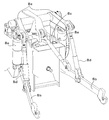
- FIG. 15 shows a tractor 1 which is an example of a work vehicle.
- the work vehicle will be described by taking the tractor 1 as an example, but the work vehicle is not limited to the tractor and may be a rice transplanter or a combine harvester.
- the tractor 1 includes a traveling vehicle body 3 having a traveling device 7, a prime mover 4, and a transmission 5.
- the traveling device 7 is a device having a front wheel 7F and a rear wheel 7R.
- the front wheel 7F may be a tire type or a crawler type.
- the rear wheel 7R may also be a tire type or a crawler type.
- the prime mover 4 is a diesel engine, an electric motor, or the like.
- the transmission 5 can switch the propulsive force of the traveling device 7 by shifting, and can also switch the traveling device 7 forward and backward.
- a cabin 9 is provided in the traveling vehicle body 3, and a driver's seat 10 is provided in the cabin 9.
- a connecting device is provided at the rear of the traveling vehicle body 3.
- the connecting device is a lifting device 8 or the like that connects the working device 2 and the traveling vehicle body 3 and does not lift or lower, and is composed of a three-point link mechanism or the like and moves up and down.
- the working device 2 is attached to and detached from the connecting device. By connecting the working device 2 to the connecting device, the working device 2 can be towed by the traveling vehicle body 3.
- the work device 2 includes a cultivating device for cultivating, a fertilizer spraying device for spraying fertilizer, a transplanting device for planting seedlings, a irrigation device for irrigating, a pesticide spraying device for spraying pesticides, a sowing spraying device for spraying seeds, and cutting of grass and the like.
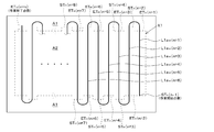
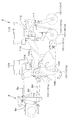
- FIG. 14 shows a composite device which is one of the working devices 2.
- the composite device shown in FIG. 14 includes a plurality of working units 101.
- the plurality of working units 101 include a first working unit 101a, a second working unit 101b, a third working unit 101c, a fourth working unit 101d, a fifth working unit 101e, and a sixth working unit 101f. ..
- the first working unit 101a, the second working unit 101b, the third working unit 101c, the fourth working unit 101d, the fifth working unit 101e, and the sixth working unit 101f are arranged in order from the front to the rear, and are arranged in the frontmost position.
- the first working unit 101a is located, and the sixth working unit 101f is located at the rearmost position.
- the first working unit 101a is a fertilizer application nozzle for spraying the fertilizer charged in the container 102, and is connected to a feeding machine 104 for feeding the fertilizer in the container 102 via a hose 103.
- the first working unit 101a sprays the fertilizer delivered to the hose 103 to the field (ground) by driving the feeding machine 104.
- the second working unit 101b is a tilling claw for tilling a field, and is attached to a rotating shaft 106 rotated by a drive mechanism 105. By driving the drive mechanism 105, the second working unit 101b rotates with the rotation of the rotating shaft 106 to cultivate the field.
- the third working unit 101c is a leveling cover arranged behind the second working unit 101b and leveles the ground after plowing.
- the fertilizer application device is composed of the first working unit 101a, the second working unit 101b, and the third working unit 101c.
- the fourth working unit 101d is a groove forming disc that forms a groove.
- the fifth working unit 101e is a sowing nozzle for sowing seeds (seed) put into the container 110, and is connected to a feeding machine 112 for feeding out the seeds of the container 110 via a hose 111.
- the fifth working unit 101e sows the seeds fed to the hose 111 by driving the feeding machine 112 into the groove formed by the fourth working unit 101d.
- the sixth working unit 101f is a rotatably supported suppression roller that suppresses at least the seeded portion.
- the sowing device is composed of the fourth working unit 101d, the fifth working unit 101e, and the sixth working unit 101f.
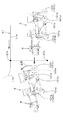
- the first working unit 101a, the second working unit 101b, the third working unit 101c, the fourth working unit 101d, the fifth working unit 101e, and the sixth working unit 101f are supported by the frame 115 and are lifted and lowered. It is designed to rise or fall according to 8. That is, the fertilizer application device and the sowing device have a frame 115 and are supported by the lift arm 8a, the lower link 8b, the top link 8c, the lift rod 8d, and the lift cylinder 8e shown in FIG. Further, the feeding machine 104, the driving mechanism 105, and the feeding machine 112 are driven (operated) by the rotation of the PTO shaft protruding from the rear portion of the traveling vehicle body 3.
- the lifting device 8 has a lift arm 8a, a lower link 8b, a top link 8c, a lift rod 8d, and a lift cylinder 8e.
- the front end portion of the lift arm 8a is swingably supported upward or downward above the rear upper portion of a case (transmission case) accommodating the transmission 5.
- the lift arm 8a swings (elevates) by being driven by the lift cylinder 8e.
- the lift cylinder 8e is composed of a hydraulic cylinder.
- the lift cylinder 8e is connected to the hydraulic pump via a control valve 36.
- the control valve 36 is a solenoid valve or the like, and expands and contracts the lift cylinder 8e.
- the front end of the lower link 8b is swingably supported above or below the rear lower part of the transmission 5.
- the front end portion of the top link 8c is swingably supported above or below the rear portion of the transmission 5 above the lower link 8b.
- the lift rod 8d connects the lift arm 8a and the lower link 8b.
- the working device 2 is connected to the rear part of the lower link 8b and the rear part of the top link 8c.
- the lift cylinder 8e is driven (expanded / contracted)
- the lift arm 8a moves up and down
- the lower link 8b connected to the lift arm 8a moves up and down via the lift rod 8d.
- the working device 2 swings (up and down) upward or downward with the front portion of the lower link 8b as a fulcrum.
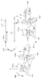
- the tractor 1 includes a steering device 29.
- the steering device 29 includes a steering wheel (steering wheel) 30, a rotating shaft (steering shaft) 31 that rotates with the rotation of the steering wheel 30, and an auxiliary mechanism (power steering mechanism) 32 that assists the steering of the steering wheel 30.
- the auxiliary mechanism 32 includes a hydraulic pump 33, a control valve 34 to which hydraulic oil discharged from the hydraulic pump 33 is supplied, and a steering cylinder 35 operated by the control valve 34.
- the control valve 34 is a solenoid valve that operates based on a control signal.
- the control valve 34 is, for example, a three-position switching valve that can be switched by moving the spool or the like.
- the control valve 34 can also be switched by steering the steering shaft 31.
- the steering cylinder 35 is connected to an arm (knuckle arm) that changes the direction of the front wheels 7F.
- the steering device 29 described above is an example, and is not limited to the configuration described above.
- the tractor 1 includes a positioning device 40.
- the positioning device 40 can detect its own position (positioning information including latitude and longitude) by a satellite positioning system (positioning satellite) such as D-GPS, GPS, GLONASS, Hokuto, Galileo, and Michibiki.
- a satellite positioning system positioning satellite
- the positioning device 40 receives the satellite signal (position of the positioning satellite, transmission time, correction information, etc.) transmitted from the positioning satellite, and based on the satellite signal, the position of the tractor 1 (for example, latitude, longitude). That is, the vehicle body position is detected.
- the positioning device 40 includes a receiving device 41 and an inertial measurement unit (IMU) 42.
- the receiving device 41 is a device having an antenna or the like and receiving a satellite signal transmitted from the positioning satellite, and is attached to the traveling vehicle body 3 separately from the inertial measurement unit 42. In this embodiment, the receiving device 41 is attached to the traveling vehicle body 3, that is, the cabin 9.
- the mounting location of the receiving device 41 is not limited to the embodiment.
- the inertial measurement unit 42 includes an acceleration sensor that detects acceleration, a gyro sensor that detects angular velocity, and the like.
- the traveling vehicle body 3, for example, provided below the driver's seat 10, can detect the roll angle, pitch angle, yaw angle, etc. of the traveling vehicle body 3 by the inertial measurement unit 42.
- the tractor 1 includes a display device 50.
- the display device 50 includes a control unit 51, a display unit 52, and a storage unit 53.
- the control unit 51 is composed of a CPU, an electric / electronic circuit, and the like, and performs various controls related to the display device 50.
- the display unit 52 is composed of a liquid crystal panel, a touch panel, other panels, and the like, and displays various information.
- the storage unit 53 is composed of a non-volatile memory or the like.
- an application program that supports the work of the tractor 1 is stored in the storage unit 53, and when the application program is started, the display device 50 operates as a work support device that supports the work. Even when the display device 50 operates as a work support device, the control unit 51, which is hardware, executes the process as the work support device.
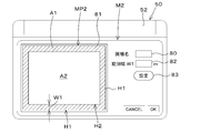
- the display device (work support device) 50 includes a map registration unit 51A.
- the map registration unit 51A registers the contour of a predetermined field, for example, the position corresponding to the contour of the predetermined field.
- the map registration unit 51A displays the map registration screen M1 on the display unit 52.
- field identification information such as the map MP1 including the field, the vehicle body position VP1 of the tractor 1, the field name, and the field management number is displayed.
- the map MP1 is associated with position information such as latitude and longitude.
- the map registration screen M1 displays the current vehicle body position VP1 detected by the positioning device 40 when the tractor 1 orbits.
- the map registration unit 51A has a plurality of tractors 1 when the tractor 1 laps.
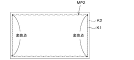
- the traveling locus K1 obtained by the vehicle body position is used as the field contour (outer shape) H1, and the field map MP2 represented by the contour H1 is registered together with the field identification information.
- the map registration unit 51A calculates the inflection point from the traveling locus indicated by the vehicle body position VP1 and registers the contour K2 connecting the inflection points as the field contour H1 (field map MP2).
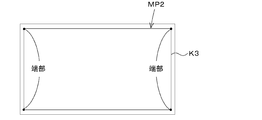
- the driver or the like designates the end of the field by a switch or the like provided on the tractor 1, and the contour K3 connecting the designated ends. May be registered as contour H1 (field map MP2).
- the above-mentioned field registration method is an example and is not limited.
- the outline of the field may be the data indicated by the position (latitude, longitude) or the data indicated by the coordinate (X-axis, Y-axis) system, or may be expressed in other expressions. It may be the data shown.
- the storage unit 53 stores the field map MP2 showing the contour (outer shape) registered by the map registration unit 51A. That is, the storage unit 53 stores the field map MP2 and data indicating the contour of the field (data for representing a predetermined field).
- the display device (work support device) 50 includes an area setting unit 51D.
- the area setting unit 51D sets the work area A2.
- the area setting unit 51D displays the work setting screen M2 on the display unit 52.
- the work setting screen M2 has a field input unit 80 and a field display unit 81.
- the field input unit 80 can input field identification information such as a field name and a field management number.
- the field display unit 81 displays a field map MP2 indicating a predetermined field corresponding to the field identification information input to the field input unit 80. That is, the area setting unit 51D requests the storage unit 53 for the field map MP2 corresponding to the field identification information input to the field input unit 80, and the field map MP2 transmitted from the storage unit 53 is the field display unit 81. To display.
- the area setting unit 51D displays the turning area A1 on the field map MP2 displayed on the field display unit 81.
- the area setting unit 51D sets the area surrounded by the contour H2 formed by offsetting the contour H1 of the field map MP2 inward by the turning width W1 as the work area A2.
- the work area A2 is set on the field map MP2 by designating the contour position of the work area A2 on the field map MP2 displayed on the field display unit 81 using a pointer or the like. You may.
- the storage unit 53 stores data indicating the position of the work area A2 (data of the field map MP2 in which the work area A2 is set).
- the display device (work support device) 50 includes a route creation unit 51B.
- the route creation unit 51B creates a travel route (planned travel route) L1 of the traveling vehicle body 3 on the field map MP2 with reference to the field map MP2 registered in the storage unit 53.
- the route creation unit 51B displays the route setting screen M3 on the display unit 52.
- the route setting screen M3 includes a route display unit 85 for displaying the planned travel route L1 and a width input unit 86.
- the work width W2 of the work device 2 is a width (work execution width) at which the work device 2 works on the ground such as a field, and in the case of the work device 2 for spraying the material on the field, the material is supplied. The spray width.
- the fertilizer application width is the work width W2
- the chemical spray width is the work width W2
- the seedlings are seeded in one operation.
- the planting width that can be planted in the field is the working width, and in the case of a sowing device, the sowing width is the working width W2.
- the ground work is a farming work performed on a field and crops cultivated in the field. For example, planting seedlings, irrigation, spraying chemicals, spraying fertilizer (fertilizer application), spraying seeds (sowing), etc. Suppression, soil cover, ridge formation, tillage, groove shape, etc.
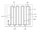
- the route creation unit 51B When the route creation unit 51B acquires the work width W2, as shown in FIG. 7A, the route creation unit 51B divides the work area A2 in the vertical direction or the horizontal direction by the work width W2, thereby performing work on the work device 2. Create A3 in the work area A2. That is, the route creation unit 51B creates a plurality of unit work sections A3 having the same width as the work width W2 in the work area A2. As shown in FIG. 7B, the route creation unit 51B may create a plurality of unit work sections A3 having a width W4 obtained by subtracting the overlap width W3 from the work width W2 in the work area A2. The overlap width W3 can be input on the route setting screen M3. That is, when the traveling vehicle body 3 to which the work device 2 is connected is driven, the route creation unit 51B sets the minimum unit area in which the work is performed on the field by the work device 2 as the unit work section A3. ..
- the route creation unit 51B creates a straight-ahead portion (straight-ahead route) L1a in which the traveling vehicle body 3 goes straight for each unit work section A3 of the field map MP2. That is, the route creation unit 51B, for example, travels straight in the central portion of the unit work compartment A3 in the width direction, at both ends in the longitudinal direction of the unit work compartment A3, and extends over the turning area A1, the work area A2, and the boundary X1. Create route L1a. Further, the route creation unit 51B creates a turning portion (turning route) L1b connecting the ends of the adjacent straight routes L1a. That is, the route creation unit 51B creates a turning route L1b at least in the turning area A1.
- the route creation unit 51B can associate the planned travel route L1 with the vehicle speed (moving speed) of the tractor 1 (traveling vehicle body 3). For example, it is assumed that a vehicle speed input unit for inputting a vehicle speed is provided on the route setting screen M3, and the vehicle speed is input to the vehicle speed input unit. The route creation unit 51B associates the straight route L1a with the vehicle speed input to the vehicle speed input unit.
- the planned travel route L1 (straight route L1a and turning route L1b) created by the route creation unit 51B is stored in the storage unit 53.
- the display device (work support device) 50 includes a work setting unit 51H.
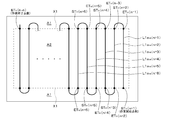
- the work setting unit 51H sets the work start and work end in the work device 2. As shown in FIG. 9A, the work setting unit 51H sets the boundary X1 between the work area A2 and the turning area A1 as the work start position STn and the work end position ETn. Alternatively, the work start position STn and the work end position ETn are set on the planned travel route L1.
- the work start position STn and the work end position ETn are arranged in a line along the boundary X1.
- at least the adjacent work start position STn and work end position ETn are aligned at the same position in the front-rear direction of the traveling vehicle body 3 (work device 2).
- the work setting unit 51H can set the work start position STn and the work end position ETn based on the type of the work device 2.
- the traveling vehicle body 3 sets the adjacent work start position STn and work end position ETn according to the plurality of work units 101. ) To different positions in the front-back direction.
- the display device (work support device) 50 includes an information acquisition unit 51I.
- the information acquisition unit 51I acquires information about a plurality of work units 101 possessed by the work device 2.
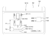
- the information acquisition unit 51I displays a machine setting screen M10 for inputting information and the like of the work unit 101 of the work device 2.
- a figure D1 imitating a tractor (working vehicle) 1 a figure D2 imitating a work device 2, a figure D3 imitating a positioning device 40, and a front work unit (front work unit) 101 are displayed.
- the figure D4 imitating the figure D4 and the figure D5 imitating the rear working part (rear working part) 101 are included.
- the working unit 101 located in the front may be referred to as “front working unit 101K”
- the working unit 101 located in the rear may be referred to as "rear working unit 101L”.
- the machine setting screen M10 also includes a first input unit 121 for inputting the first distance Y1 and a second input unit 122 for inputting the second distance Y2.
- the first input unit 121 is a portion for inputting the distance Y1 in the front-rear direction (traveling direction) between the positioning device 40 and the front working unit 101K located in front of the working device 2.
- the second input unit 122 is a portion of the work device 2 for inputting the distance Y2 between the front work unit 101K and the rear work unit 101L located behind the front work unit 101K.
- the information acquisition unit 51I acquires the distance Y2 between the front work unit 101K and the rear work unit 101L located behind the front work unit 101K as information regarding the plurality of work units 101.
- the positioning device 40, the control device 60, etc. can calculate the position of the front work unit 101K (front work unit position) based on the distance Y1 input by the first input unit 121. Further, the positioning device 40 or the control device 60 or the like calculates the position of the rear working unit 101L (rear working unit position) based on the distance Y1 input by the first input unit 121 and the distance Y2 input to the second input unit 122.
- the work device 2 can be raised and lowered, and the drive of the work device 2 can be started and stopped according to the positions of the front work unit and the rear work unit.
- the front work unit 101K and the rear work unit 101L are operated at least according to the work.
- a person (driver) or the like selects and inputs the distances Y1 and Y2 as described above according to the work.
- the first work unit 101a located at the frontmost position is in front.
- the working unit 101K is set, and the fifth working unit 101e located at the rearmost position is selected as the rear working unit 101L.
- the distance Y1 and the second are set to the first input unit 121.
- the distance Y2 may be input to the input unit 122.
- the first working unit 101a located on the frontmost side among the plurality of working units 101 is selected as the front working unit 101K
- the sixth working unit 101f located on the rearmost side is selected. Will be described as the one selected as the post-working unit 101L.
- the machine setting screen M10 has the first input unit 121 and the second input unit 122, the first distance Y1 between the positioning device 40 and the front work unit 101K, the front work unit 101K, and the rear work unit.
- the screen is not limited to this, and the position of the positioning device 40, the position of the front working unit 101K, and the position of the rear working unit 101L are mechanically set by using the pointer unit or the like. It may be specified on the screen M10, and the work setting unit 51H may obtain the first distance Y1 and the second distance Y2 from the designated position.
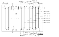
- the work setting unit 51H sets the work start position STn and the work end position ETn to different positions based on the second distance Y2. ..
- the position can be shifted in the traveling direction of 2 (the front-rear direction of the working device 2).
- the turning area A1 and the working area A2 are left as they are, and the work start position STn and the work end position ETn are set on the planned traveling route L1 (straight-ahead route L1an). As shown in FIG.
- the unit 51H shifts the work area A2 to the turning area A1 by at least the second distance Y2 or more with the width of the unit work section A3, and moves on the boundary X1 between the working area A2 and the turning area A1.
- the work start position STn and the work end position ETn may be set.
- the tractor 1 includes a control device 60.
- the control device 60 is a device that controls the traveling system, the working system, and the like in the tractor 1.
- An operation changeover switch 65 is connected to the control device 60.
- the operation changeover switch 65 is a switch that can be switched ON / OFF, and when it is ON, the control device 60 can be set to the automatic operation mode, and when it is OFF, the control device 60 is set to the manual operation mode. Can be set.
- the control device 60 includes an automatic operation control unit 63.
- the automatic operation control unit 63 is composed of an electric / electronic circuit provided in the control device 60, a program stored in a CPU, and the like.
- the automatic driving control unit 63 controls the automatic driving of the traveling vehicle body 3.
- the automatic operation control unit 63 starts automatic operation when the automatic operation mode is set. As shown in FIG. 11, when the deviation between the vehicle body position and the planned travel route L1 is less than the threshold value in the situation where the tractor 1 is performing automatic driving, the automatic driving control unit 63 sets the steering shaft (rotation shaft). The rotation angle of 31 is maintained.
- the automatic driving control unit 63 controls the steering direction of the tractor 1 to the right.
- the steering shaft 31 is rotated so as to be in the direction.
- the automatic driving control unit 63 sets the steering direction of the tractor 1 to the left.
- the steering shaft 31 is rotated so as to be in the direction.
- the steering angle of the steering device 29 is changed based on the deviation between the vehicle body position and the planned travel route L1, but the direction of the planned travel route L1 and the progress of the tractor 1 (traveling vehicle body 3).
- the direction (traveling direction) is different from the orientation (vehicle body orientation), that is, when the angle of the vehicle body orientation with respect to the planned traveling route L1 is equal to or greater than the threshold value, the automatic operation control unit 63 has zero angle (vehicle body orientation F1 travels).
- the steering angle may be set so as to match the direction of the planned route L1).
- the automatic driving control unit 63 sets the final steering angle in automatic driving based on the steering angle obtained based on the deviation (positional deviation) and the steering angle obtained based on the direction (direction deviation). You may.
- the setting of the steering angle in the automatic operation in the above-described embodiment is an example and is not limited.
- the automatic driving control unit 63 sets the transmission stage of the transmission so that the vehicle speed of the current tractor 1 matches the vehicle speed corresponding to the planned travel route L1. Automatically change the number of revolutions of the prime mover. As shown in FIGS. 9B and 9C, when the work start position STn and the work end position ETn are set to different positions in the front-rear direction in the traveling direction (traveling vehicle body 3), the lifting device 8 is moved by the work setting unit 51H. The work device 2 is moved up and down based on the changed work start position STn and work end position ETn. Further, the automatic operation control unit 63 controls the work device 2 based on the work start position STn and the work end position ETn changed by the work setting unit 51H.
- the automatic operation control unit 63 is traveling while lowering the work device 2 and performing automatic operation along the straight route L1a (under the situation where the ground work is being performed).
- the work device 2 passes the work end position ETn
- the work device 2 is raised by the elevating device 8.
- the work device 2 sets the work start position STn.
- the lifting device 8 lowers the working device 2.
- the automatic operation control unit 63 stops driving the work device 2 when the work device 2 passes the work end position ETn in a situation where the work is being performed on the ground.
- the automatic operation control unit 63 starts driving the work device 2 when the work device 2 passes the work start position STn, at least in a situation where the work device 2 is traveling while performing automatic operation along the turning route L1b (work). Start the work of the device 2).
- the automatic operation control unit 63 starts when the suppression roller (sixth work unit 101f) passes the work end position ETn (post-work unit). When the locus of the position crosses the work end position ETn), a rise signal is output to the control valve 36 to raise the work device 2. Further, the automatic operation control unit 63 has a plurality of drive devices (feeding machine 104, drive mechanism 105, feeding) provided in the working device 2 when the suppression roller (sixth working unit 101f) has passed the work end position ETn. The drive of the machine 112) is stopped.
- the automatic operation control unit 63 may stop driving the drive device by outputting stop signals to each of the plurality of drive devices (feeding machine 104, driving mechanism 105, feeding machine 112). Alternatively, the automatic operation control unit 63 switches the PTO clutch 125, which can switch between the connected state in which the power of the PTO shaft is transmitted to the working device 2 and the disconnected state in which the power of the PTO shaft is not transmitted to the working device 2, from the connected state to the disconnected state. Multiple drives may be stopped.
- the automatic operation control unit 63 shifts from the turning route L1b to the straight route L1a, the automatic operation control unit 63 has the fertilizer application nozzle (first working unit 101a) at the work start position STn. (When the locus of the position of the front work portion straddles the work start position STn), the work device 2 is lowered. Further, when the fertilizer application nozzle (first working unit 101a) passes the work start position STn at the stage of shifting from the turning route L1b to the straight route L1a, the automatic operation control unit 63 sends a drive signal to the feeding machine 104 and the driving mechanism 105. Is output to drive the feeding machine 104, and the work of tilling and fertilizing is started.
- the automatic operation control unit 63 advances a predetermined distance after the fertilizer application nozzle (first working unit 101a) passes through the work start position STn, for example, when it advances less than the second distance Y2 from the work start position STn.
- the work related to the suppression roller (sixth working unit 101f) that is, the seeding is started from the seeding nozzle.
- the automatic operation control unit 63 monitors the distance between the rear work unit position and the work end position ETn during automatic operation, and when the rear work unit 101L reaches the work end position ETn, the work device 2 actually rises. Control may be performed in consideration of the responsiveness of the elevating device 8 so as to start. Similarly, the automatic operation control unit 63 monitors the distance between the front work unit position and the work start position STn during automatic operation, and actually works device 2 when the front work unit 101K reaches the work start position STn. Control may be performed in consideration of the responsiveness of the elevating device 8 so that the descent of the elevating device 8 is completed.
- a plurality of working units 101a to 101f have been described in the composite device, but as described above, when the composite device is composed of at least two or more working devices (fertilizer application device, sowing device), One fertilizer application device may be considered as a working unit, and the other seeding device may be considered as a working unit.
- the front working unit 101K is the “fertilizer application device 101K” and the rear working unit 101L is the “sowing device 101L”.
- the front working unit 101K is used as the fertilizer application device 101K and the rear working unit 101L is used as the sowing device 101L will be described.
- the first distance Y1 between the positioning device 40 and the front end 162 of the fertilizer application device 101K is input to the first input unit 121 of the machine setting screen M10.
- the second input unit 122 inputs the second distance Y2 between the front end 162 of the fertilizer application device 101K and the rear end 161 of the sowing device 101L.
- the work setting unit 51H sets the work start position STn and the work end position ETn based on the second distance Y2 by the same method described above.
- the automatic operation control unit 63 is traveling while lowering the fertilizer application device 101K and the sowing device 101L and performing automatic operation along the straight route L1a (a situation in which ground work is being performed). In the lower), when the rear end 161 of the sowing device 101L passes the work end position ETn, the fertilizer application device 101K and the sowing device 101L are raised by the elevating device 8. As shown in FIG.
- the automatic operation control unit 63 in a situation where the automatic operation control unit 63 is traveling while raising the work device 2 and performing automatic operation at least along the turning route L1b, the front end 162 of the fertilizer application device 101K starts work.
- the fertilizer application device 101K and the sowing device 101L are lowered by the elevating device 8. Further, the automatic operation control unit 63 stops driving the fertilizer application device 101K and the sowing device 101L when the rear end of the sowing device 101L passes the work end position ETn under the condition that the ground work is being performed.
- the automatic operation control unit 63 starts driving the fertilizer application device 101K when the front end 162 of the fertilizer application device 101K passes the work start position STn, at least in a situation where the vehicle is traveling while performing automatic operation along the turning route L1b. (Start the work of the fertilizer application device 101K).
- the automatic operation control unit 63 advances the seeding device by a predetermined distance after the front end 162 of the fertilizer application device 101K has passed the work start position STn, for example, when the second distance Y2 or less from the work start position STn.
- Drive 101L The work vehicle 1 includes a traveling vehicle body 3, a connecting device capable of connecting a working device 2 having a plurality of working units 101 to the traveling vehicle body 3, and automatic operation of the traveling vehicle body 3 based on the planned traveling route L1.
- the automatic operation control unit 63 is provided, and the work setting unit 51H for setting the work start position STn and the work end position ETn in the work device 2 at different positions based on the plurality of work units 101.
- the work start position STn and the work end position ETn can be set to different positions, for example, even if the work device 2 is long in the front-rear direction and the plurality of work units 101 are separated from each other, a plurality of work units 101 can be set. It is possible to suppress the formation of a place (unworked place) where work cannot be performed by at least one working unit 101 of the working unit 101. That is, even when the work is performed while traveling with the work device provided with the plurality of work units 101, the work can be accurately performed at the intended location.
- An area setting unit 51D for setting a work area A2 for performing work by the work device 2 and a turning area A1 for turning the traveling vehicle body 3 is provided, and the work setting unit 51H sets a boundary X1 between the work area A2 and the turning area A1. , The work start position STn and the work end position ETn are set. According to this, the work can be started on the boundary X1 as much as possible by the plurality of working units 101, and the work can be finished on the boundary X1 as much as possible.
- the work vehicle 1 includes a route creation unit 51B for creating a planned travel route L1 of the traveling vehicle body 3, and the work setting unit 51H has a work start position STn and a work end position in the work device 2 based on the plurality of work units 101. Set ETn on the planned travel route L1. According to this, the traveling of the tractor 1 (working device 2) by the scheduled traveling route L1 set by the route creating unit 51B can be linked with the work start at the work start position STn and the work end at the work end position ETn. It is easy and efficient to perform automatic operation.
- the work setting unit 51H sets the work end position ETn according to the position of the rear work unit 101L, which is the work unit 101 located on the rear side of the plurality of work units 101. According to this, in the presence of a plurality of work units 101, the rear work unit 101L can perform the work up to the work end position ETn set by the work setting unit 51H.
- the work setting unit 51H sets the work start position STn according to the position of the front work unit 101K, which is the work unit 101 located on the front side among the plurality of work units 101. According to this, in the presence of a plurality of work units 101, the work can be started by the front work unit 101K at the work start position STn set by the work setting unit 51H.
- the connecting device is an elevating device 8 that raises and lowers the work device 2, and raises and lowers the work device 2 based on the work start position STn and the work end position ETn changed by the work setting unit 51H. According to this, even if the positions of the work start position STn and the work end position ETn are different, the work device 2 can be stably moved up and down by the lifting device 8.
- the coupling device raises the work device 2 when the work device 2 passes the work end position ETn, and lowers the work device 2 when the work device 2 passes the work start position STn. According to this, the work can be completed by raising the work device 2 at the work end position ETn, and the work can be started by lowering the work device 2 at the work start position STn. ..
- a control device 60 that controls the work device 2 is provided based on the work start position STn and the work end position ETn changed by the work setting unit 51H. According to this, the control device 60 can stably start and end the work in the work device 2.
- the control device 60 stops the work of the rear work unit 101L when the rear work unit 101L, which is the work unit 101 located on the rear side, passes through the work end position ETn among the plurality of work units 101. According to this, when the tractor 1 (working device 2) advances beyond the work end position ETn, the position where the work ends can be made constant in the rear work unit 101L as much as possible.
- the control device 60 starts the work of the front work unit 101K when the front work unit 101K, which is the work unit 101 located on the front side, has passed the work start position STn among the plurality of work units 101. According to this, when there are a plurality of work units 101, the front work unit 101K starts the work before the rear work unit 101L, so that the work performed after the front work unit 101K can be smoothly taken over. be able to.
- the work setting unit 51H sets the work start position STn according to the position of the front work unit 101K, which is the work unit 101 located on the front side among the plurality of work units 101, and among the plurality of work units 101.
- the work end position ETn is set according to the position of the rear work unit 101L, which is the work unit 101 located on the rear side, and the control device 60 runs after the front work unit 101K starts the work at the work start position STn.
- the vehicle body 3 advances a predetermined distance
- the work of the rear work unit 101L is performed. According to this, when the work device 2 includes the front work unit 101K and the rear work unit 101L, it is possible not only to perform the work by the front work unit 101K and then take over the work by the rear work unit 101L. It is possible to reduce waste caused by the work of the post-working unit 101L starting too early.
- the plurality of working units 101 perform different operations on the ground. According to this, various operations can be performed in a complex and efficient manner.
- the work support device of the work vehicle 1 relates to an information acquisition unit 51I for acquiring information on a plurality of work units 101 included in the work device 2 connected to the traveling vehicle body 3, and a plurality of work units 101 acquired by the information acquisition unit 51I. Based on the information, the work setting unit 51H for setting the work start position STn and the work end position ETn in the work device 2 to different positions is provided.
- the work start position STn and the work end position ETn can be set to different positions, for example, even if the work device 2 is long in the front-rear direction and the plurality of work units 101 are separated from each other, a plurality of work units 101 are separated. It is possible to suppress the formation of a place (unworked place) where work cannot be performed by at least one working unit 101 of the working unit 101. That is, even when the work is performed while traveling with a work device provided with a plurality of work units, the work can be performed accurately at the intended location.
- the work support device of the work vehicle 1 includes an area setting unit 51D having a work area A2 for performing work by the work device 2 and a turning area A1 for turning the traveling vehicle body 3, and the work setting unit 51H turns with the work area A2.
- the boundary X1 with the area A1 is set as the work start position STn and the work end position ETn. According to this, the work can be started on the boundary X1 as much as possible by the plurality of working units 101, and the work can be finished on the boundary X1 as much as possible.
- the work support device of the work vehicle 1 includes a route creation unit 51B for creating a planned travel route L1 of the traveling vehicle body 3, and the work setting unit 51H has a work start position STn in the work device 2 based on the plurality of work units 101. And the work end position ETn are set on the planned travel route L1. According to this, the traveling of the tractor 1 (working device 2) by the scheduled traveling route L1 set by the route creating unit 51B can be linked with the work start at the work start position STn and the work end at the work end position ETn. It is easy and efficient to perform automatic operation.
- the tractor 1 (traveling vehicle body 3) is driven while changing the vehicle speed along the planned traveling route, but the tractor 1 (traveling vehicle body 3) is driven along the planned traveling route.
- Auto-steering auto-steering
- the driver can arbitrarily drive along the planned driving route parallel to the driving reference route by operating the switch. It also includes other automatic steering.
Abstract
Even when work is performed while a work device (2) provided with a plurality of work units (101) travels, the present invention enables work to be performed accurately at an intended place. A work vehicle (1) is provided with: a traveling vehicle body (3); a connection device that can connect the work device (2), having the plurality of work units (101), to the traveling vehicle body (3); an automatic operation control unit (63) that, on the basis of a traveling schedule route (L1) of the traveling vehicle body (3), performs automatic operation of the traveling vehicle body (3); and a work setting unit (51H) that, on the basis of the plurality of work units (101), sets a work start position (STn) and a work end position (ETn) in the work device (2) to respectively different positions.
Description
本発明は、例えば、トラクタ等の作業車両及び作業車両の作業支援装置に関する。
The present invention relates to, for example, a work vehicle such as a tractor and a work support device for the work vehicle.
従来、トラクタ等の作業車両を自動運転させるための走行経路(作業走行ライン)を作成する技術として特許文献1に示す技術が知られている。特許文献1の作業車は、圃場の外周部の位置データを取得する取得部と、位置データに基づいて走行機体が走行する作業走行ラインを圃場に設定する作業設定部とを備えている。
Conventionally, the technique shown in Patent Document 1 is known as a technique for creating a running path (working running line) for automatically driving a work vehicle such as a tractor. The work vehicle of Patent Document 1 includes an acquisition unit that acquires position data of the outer peripheral portion of the field, and a work setting unit that sets a work travel line on which the traveling machine travels in the field based on the position data.
特許文献1では、作業走行ラインを作成することができ、作業走行ラインに沿って自動運転をしながら作業が行えるものの、作業装置の種類によっては、作業を行いたい圃場に対して、作業を行った箇所と、作業が行えなかった箇所とが発生することがある。
そこで、本発明は上記問題点に鑑み、複数の作業部を備えた作業装置で走行しながら作業を行う場合であっても意図した箇所で作業を正確に行うことができる作業車両及び作業車両の支援装置を提供することを目的とする。 InPatent Document 1, a work running line can be created, and work can be performed while performing automatic operation along the work running line. However, depending on the type of work device, work is performed on a field to be worked on. There may be some parts where the work was not possible and some parts where the work could not be performed.
Therefore, in view of the above problems, the present invention relates to a work vehicle and a work vehicle capable of accurately performing work at an intended location even when the work is performed while traveling with a work device provided with a plurality of work units. The purpose is to provide a support device.
そこで、本発明は上記問題点に鑑み、複数の作業部を備えた作業装置で走行しながら作業を行う場合であっても意図した箇所で作業を正確に行うことができる作業車両及び作業車両の支援装置を提供することを目的とする。 In
Therefore, in view of the above problems, the present invention relates to a work vehicle and a work vehicle capable of accurately performing work at an intended location even when the work is performed while traveling with a work device provided with a plurality of work units. The purpose is to provide a support device.
この技術的課題を解決するための本発明の技術的手段は、以下に示す点を特徴とする。
作業車両は、走行車体と、複数の作業部を有する作業装置を前記走行車体に連結可能な連結装置と、前記走行車体を走行予定ルートに基づいて前記走行車体の自動運転を行う自動運転制御部と、前記複数の作業部に基づいて、前記作業装置における作業開始位置と作業終了位置とを異なる位置に設定する作業設定部と、を備えている。 The technical means of the present invention for solving this technical problem is characterized by the following points.
The work vehicle includes a traveling vehicle body, a connecting device capable of connecting a traveling vehicle body and a work device having a plurality of working units to the traveling vehicle body, and an automatic driving control unit that automatically drives the traveling vehicle body based on a planned traveling route. A work setting unit for setting a work start position and a work end position in the work apparatus at different positions based on the plurality of work units.
作業車両は、前記作業装置によって作業を行う作業エリアと、前記走行車体を旋回させる旋回エリアとをエリア設定部を備え、前記作業設定部は、前記作業エリアと前記旋回エリアとの境界ラインの位置を、前記作業開始位置と作業終了位置として設定する。
作業車両は、前記走行車体の走行予定ルートを作成するルート作成部を備え、前記作業設定部は、前記複数の作業部に関する情報に基づいて、前記作業装置における作業開始位置と作業終了位置とを前記走行予定ルート上に設定する。 The work vehicle includes an area setting unit having a work area for performing work by the work device and a turning area for turning the traveling vehicle body, and the work setting unit is a position of a boundary line between the work area and the turning area. Is set as the work start position and the work end position.
The work vehicle includes a route creation unit that creates a planned travel route of the traveling vehicle body, and the work setting unit sets a work start position and a work end position in the work device based on information about the plurality of work units. It is set on the planned travel route.
前記作業設定部は、前記複数の作業部のうち、後方側に位置する作業部である後作業部の位置に応じて前記作業終了位置を設定する。
前記作業設定部は、前記複数の作業部のうち、前方側に位置する作業部である前作業部の位置に応じて前記作業開始位置を設定する。
前記連結装置は、前記作業装置を昇降する昇降装置であり、前記作業設定部によって変更された前記作業開始位置と前記作業終了位置とに基づいて、前記作業装置を昇降させる。 The work setting unit sets the work end position according to the position of the rear work unit, which is a work unit located on the rear side of the plurality of work units.
The work setting unit sets the work start position according to the position of the front work unit, which is a work unit located on the front side, among the plurality of work units.
The connecting device is an elevating device that raises and lowers the work device, and raises and lowers the work device based on the work start position and the work end position changed by the work setting unit.
前記連結装置は、前記作業装置が前記作業終了位置を通過する場合に前記作業装置の上昇を行い、且つ、前記作業装置が前記作業開始位置を通過する場合に前記作業装置の下降を行う。
前記作業設定部によって変更された前記作業開始位置と前記作業終了位置とに基づいて、前記作業装置を制御する制御装置を備えている。 The connecting device raises the work device when the work device passes the work end position, and lowers the work device when the work device passes the work start position.
A control device for controlling the work device is provided based on the work start position and the work end position changed by the work setting unit.
前記制御装置は、前記複数の作業部のうち、後方側に位置する作業部である後作業部が前記作業終了位置を通過する場合に前記後作業部の作業を停止する。
前記制御装置は、前記複数の作業部のうち、前方側に位置する作業部である前作業部が前記作業開始位置を通過した場合に前記前作業部の作業を開始する。
前記作業設定部は、前記複数の作業部のうち、前方側に位置する作業部である前作業部の位置に応じて前記作業開始位置を設定し、且つ、前記複数の作業部のうち、後方側に位置する作業部である後作業部の位置に応じて前記作業終了位置を設定し、前記制御装置は、前記前作業部が前記作業開始位置で作業を開始してから前記走行車体が所定距離進んだ時点で前記後作業部の作業を行う。 The control device stops the work of the rear work unit when the rear work unit, which is a work unit located on the rear side, passes through the work end position among the plurality of work units.
The control device starts the work of the front work unit when the front work unit, which is a work unit located on the front side, has passed the work start position among the plurality of work units.
The work setting unit sets the work start position according to the position of the front work unit, which is a work unit located on the front side of the plurality of work units, and is rearward of the plurality of work units. The work end position is set according to the position of the rear work unit, which is a work unit located on the side, and the control device determines the traveling vehicle body after the front work unit starts work at the work start position. When the distance is advanced, the work of the post-working unit is performed.
前記複数の作業部は、対地に対して異なる作業を行う。
作業車両の作業支援装置は、走行車体に連結される作業装置が有する複数の作業部に関する情報を取得する情報取得部と、前記情報取得部が取得した前記複数の作業部に関する情報に基づいて、前記作業装置における作業開始位置と作業終了位置とを異なる位置に設定する作業設定部と、を備えている。 The plurality of working units perform different operations on the ground.
The work support device of the work vehicle is based on an information acquisition unit that acquires information on a plurality of work units of the work device connected to the traveling vehicle body and information on the plurality of work units acquired by the information acquisition unit. It is provided with a work setting unit for setting a work start position and a work end position in the work device at different positions.
作業車両の作業支援装置は、前記作業装置によって作業を行う作業エリアと、前記走行車体を旋回させる旋回エリアとをエリア設定部を備え、前記作業設定部は、前記作業エリアと前記旋回エリアとの境界ラインの位置を、前記作業開始位置と作業終了位置として設定する。
作業車両の作業支援装置は、前記走行車体の走行予定ルートを作成するルート作成部を備え、前記作業設定部は、前記複数の作業部に関する情報に基づいて、前記作業装置における作業開始位置と作業終了位置とを前記走行予定ルート上に設定する。 The work support device of the work vehicle includes an area setting unit having a work area for performing work by the work device and a turning area for turning the traveling vehicle body, and the work setting unit has the work area and the turning area. The positions of the boundary lines are set as the work start position and the work end position.
The work support device of the work vehicle includes a route creation unit that creates a planned travel route of the traveling vehicle body, and the work setting unit has a work start position and work in the work device based on information about the plurality of work units. The end position is set on the planned travel route.
作業車両の作業支援装置は、前記作業設定部は、前記複数の作業部のうち、後方側に位置する作業部である後作業部の位置に応じて前記作業終了位置を設定する。
前記作業設定部は、前記複数の作業部のうち、前方側に位置する作業部である前作業部の位置に応じて前記作業開始位置を設定する。 In the work support device of the work vehicle, the work setting unit sets the work end position according to the position of the rear work unit, which is the work unit located on the rear side of the plurality of work units.
The work setting unit sets the work start position according to the position of the front work unit, which is a work unit located on the front side, among the plurality of work units.
本発明によれば、複数の作業部を備えた作業装置で走行しながら作業を行う場合であっても意図した箇所で作業を正確に行うことができる。
According to the present invention, even when the work is performed while traveling with a work device provided with a plurality of work units, the work can be performed accurately at the intended location.
以下、本発明の実施の形態を図面に基づいて説明する。
図15は、作業車両の一例であるトラクタ1を示している。作業車両について、トラクタ1を例にあげ説明するが、作業車両は、トラクタに限定されず、田植機、コンバインであってもよい。
図15に示すように、トラクタ1は、走行装置7を有する走行車体3と、原動機4と、変速装置5とを備えている。走行装置7は、前輪7F及び後輪7Rを有する装置である。前輪7Fは、タイヤ型であってもクローラ型であってもよい。また、後輪7Rも、タイヤ型であってもクローラ型であってもよい。原動機4は、ディーゼルエンジン、電動モータ等である。変速装置5は、変速によって走行装置7の推進力を切換可能であると共に、走行装置7の前進、後進の切換が可能である。走行車体3にはキャビン9が設けられ、当該キャビン9内には運転席10が設けられている。 Hereinafter, embodiments of the present invention will be described with reference to the drawings.
FIG. 15 shows atractor 1 which is an example of a work vehicle. The work vehicle will be described by taking the tractor 1 as an example, but the work vehicle is not limited to the tractor and may be a rice transplanter or a combine harvester.
As shown in FIG. 15, thetractor 1 includes a traveling vehicle body 3 having a traveling device 7, a prime mover 4, and a transmission 5. The traveling device 7 is a device having a front wheel 7F and a rear wheel 7R. The front wheel 7F may be a tire type or a crawler type. Further, the rear wheel 7R may also be a tire type or a crawler type. The prime mover 4 is a diesel engine, an electric motor, or the like. The transmission 5 can switch the propulsive force of the traveling device 7 by shifting, and can also switch the traveling device 7 forward and backward. A cabin 9 is provided in the traveling vehicle body 3, and a driver's seat 10 is provided in the cabin 9.
図15は、作業車両の一例であるトラクタ1を示している。作業車両について、トラクタ1を例にあげ説明するが、作業車両は、トラクタに限定されず、田植機、コンバインであってもよい。
図15に示すように、トラクタ1は、走行装置7を有する走行車体3と、原動機4と、変速装置5とを備えている。走行装置7は、前輪7F及び後輪7Rを有する装置である。前輪7Fは、タイヤ型であってもクローラ型であってもよい。また、後輪7Rも、タイヤ型であってもクローラ型であってもよい。原動機4は、ディーゼルエンジン、電動モータ等である。変速装置5は、変速によって走行装置7の推進力を切換可能であると共に、走行装置7の前進、後進の切換が可能である。走行車体3にはキャビン9が設けられ、当該キャビン9内には運転席10が設けられている。 Hereinafter, embodiments of the present invention will be described with reference to the drawings.
FIG. 15 shows a
As shown in FIG. 15, the
また、走行車体3の後部には、連結装置が設けられている。連結装置は、作業装置2と走行車体3とを連結し且つ昇降を行わないスイングドローバ、3点リンク機構等で構成されて昇降を行う昇降装置8等である。連結装置には、作業装置2が着脱可能である。作業装置2を連結装置に連結することによって、走行車体3によって作業装置2を牽引することができる。作業装置2は、耕耘する耕耘装置、肥料を散布する肥料散布装置、苗を植え付ける移植装置、灌水を行う灌水装置、農薬を散布する農薬散布装置、種を散布する播種散布装置、牧草等の刈取を行う刈取装置、牧草等の拡散を行う拡散装置、牧草等の集草を行う集草装置、牧草等の成形を行う成形装置、複数の作業を行う複合装置等である。
In addition, a connecting device is provided at the rear of the traveling vehicle body 3. The connecting device is a lifting device 8 or the like that connects the working device 2 and the traveling vehicle body 3 and does not lift or lower, and is composed of a three-point link mechanism or the like and moves up and down. The working device 2 is attached to and detached from the connecting device. By connecting the working device 2 to the connecting device, the working device 2 can be towed by the traveling vehicle body 3. The work device 2 includes a cultivating device for cultivating, a fertilizer spraying device for spraying fertilizer, a transplanting device for planting seedlings, a irrigation device for irrigating, a pesticide spraying device for spraying pesticides, a sowing spraying device for spraying seeds, and cutting of grass and the like. A cutting device for performing grass, a spreading device for spreading grass, a grass collecting device for collecting grass, a molding device for molding grass, a composite device for performing a plurality of operations, and the like.
図14は、作業装置2の1つである複合装置を示している。図14に示す複合装置は、複数の作業部101を備えている。複数の作業部101は、第1作業部101aと、第2作業部101bと、第3作業部101cと、第4作業部101d、第5作業部101e、第6作業部101fとを含んでいる。第1作業部101a、第2作業部101b、第3作業部101c、第4作業部101d、第5作業部101e及び第6作業部101fは、前方から後方に順番に並んでいて、最も前方には第1作業部101aが位置し、最も後方には、第6作業部101fが位置する。
FIG. 14 shows a composite device which is one of the working devices 2. The composite device shown in FIG. 14 includes a plurality of working units 101. The plurality of working units 101 include a first working unit 101a, a second working unit 101b, a third working unit 101c, a fourth working unit 101d, a fifth working unit 101e, and a sixth working unit 101f. .. The first working unit 101a, the second working unit 101b, the third working unit 101c, the fourth working unit 101d, the fifth working unit 101e, and the sixth working unit 101f are arranged in order from the front to the rear, and are arranged in the frontmost position. The first working unit 101a is located, and the sixth working unit 101f is located at the rearmost position.
第1作業部101aは、容器102に投入された肥料を散布する施肥ノズルであり、ホース103を介して容器102の肥料を繰り出す繰出機104に接続されている。第1作業部101aは、繰出機104を駆動することによってホース103に繰り出された肥料を圃場(対地)に散布する。第2作業部101bは、圃場を耕耘する耕耘爪であり、駆動機構105によって回転する回転軸106に取り付けられている。第2作業部101bは、駆動機構105を駆動することによって、回転軸106の回転に伴って回転して圃場を耕耘する。第3作業部101cは、第2作業部101bの後方に配置された整地カバーであって、耕耘した後の地面を均す。図14の複合装置の場合、第1作業部101a、第2作業部101b及び第3作業部101cによって施肥装置が構成されている。
The first working unit 101a is a fertilizer application nozzle for spraying the fertilizer charged in the container 102, and is connected to a feeding machine 104 for feeding the fertilizer in the container 102 via a hose 103. The first working unit 101a sprays the fertilizer delivered to the hose 103 to the field (ground) by driving the feeding machine 104. The second working unit 101b is a tilling claw for tilling a field, and is attached to a rotating shaft 106 rotated by a drive mechanism 105. By driving the drive mechanism 105, the second working unit 101b rotates with the rotation of the rotating shaft 106 to cultivate the field. The third working unit 101c is a leveling cover arranged behind the second working unit 101b and leveles the ground after plowing. In the case of the composite device of FIG. 14, the fertilizer application device is composed of the first working unit 101a, the second working unit 101b, and the third working unit 101c.
第4作業部101dは、溝を形成する溝形成ディスクである。第5作業部101eは、容器110に投入された種(種子)を播種する播種ノズルであり、ホース111を介して容器110の種子を繰り出す繰出機112に接続されている。第5作業部101eは、繰出機112を駆動することによってホース111に繰り出された播種を第4作業部101dにて形成した溝に播種する。第6作業部101fは、回転自在に支持された鎮圧ローラであって、少なくとも播種された部分を鎮圧する。図14の複合装置の場合、第4作業部101d、第5作業部101e及び第6作業部101fによって播種装置が構成されている。
The fourth working unit 101d is a groove forming disc that forms a groove. The fifth working unit 101e is a sowing nozzle for sowing seeds (seed) put into the container 110, and is connected to a feeding machine 112 for feeding out the seeds of the container 110 via a hose 111. The fifth working unit 101e sows the seeds fed to the hose 111 by driving the feeding machine 112 into the groove formed by the fourth working unit 101d. The sixth working unit 101f is a rotatably supported suppression roller that suppresses at least the seeded portion. In the case of the composite device of FIG. 14, the sowing device is composed of the fourth working unit 101d, the fifth working unit 101e, and the sixth working unit 101f.
第1作業部101aと、第2作業部101bと、第3作業部101cと、第4作業部101d、第5作業部101e、第6作業部101fは、フレーム115によって支持されていて、昇降装置8によって上昇又は下降するようになっている。即ち、施肥装置及び播種装置は、フレーム115を有していて、図2に示すリフトアーム8a、ロアリンク8b、トップリンク8c、リフトロッド8d、リフトシリンダ8eに昇降自在に支持されている。また、繰出機104、駆動機構105及び繰出機112は、走行車体3の後部から突出したPTO軸の回転によって駆動(作動)する。
The first working unit 101a, the second working unit 101b, the third working unit 101c, the fourth working unit 101d, the fifth working unit 101e, and the sixth working unit 101f are supported by the frame 115 and are lifted and lowered. It is designed to rise or fall according to 8. That is, the fertilizer application device and the sowing device have a frame 115 and are supported by the lift arm 8a, the lower link 8b, the top link 8c, the lift rod 8d, and the lift cylinder 8e shown in FIG. Further, the feeding machine 104, the driving mechanism 105, and the feeding machine 112 are driven (operated) by the rotation of the PTO shaft protruding from the rear portion of the traveling vehicle body 3.
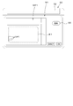
図2に示すように、昇降装置8は、リフトアーム8a、ロアリンク8b、トップリンク8c、リフトロッド8d、リフトシリンダ8eを有している。リフトアーム8aの前端部は、変速装置5を収容するケース(ミッションケース)の後上部に上方又は下方に揺動可能に支持されている。リフトアーム8aは、リフトシリンダ8eの駆動によって揺動(昇降)する。リフトシリンダ8eは、油圧シリンダから構成されている。リフトシリンダ8eは、制御弁36を介して油圧ポンプと接続されている。制御弁36は、電磁弁等であって、リフトシリンダ8eを伸縮させる。
As shown in FIG. 2, the lifting device 8 has a lift arm 8a, a lower link 8b, a top link 8c, a lift rod 8d, and a lift cylinder 8e. The front end portion of the lift arm 8a is swingably supported upward or downward above the rear upper portion of a case (transmission case) accommodating the transmission 5. The lift arm 8a swings (elevates) by being driven by the lift cylinder 8e. The lift cylinder 8e is composed of a hydraulic cylinder. The lift cylinder 8e is connected to the hydraulic pump via a control valve 36. The control valve 36 is a solenoid valve or the like, and expands and contracts the lift cylinder 8e.
ロアリンク8bの前端部は、変速装置5の後下部に上方又は下方に揺動可能に支持されている。トップリンク8cの前端部は、ロアリンク8bよりも上方において、変速装置5の後部に上方又は下方に揺動可能に支持されている。リフトロッド8dは、リフトアーム8aとロアリンク8bとを連結している。ロアリンク8bの後部及びトップリンク8cの後部には、作業装置2が連結される。リフトシリンダ8eが駆動(伸縮)すると、リフトアーム8aが昇降するとともに、リフトロッド8dを介してリフトアーム8aと連結されたロアリンク8bが昇降する。これにより、作業装置2がロアリンク8bの前部を支点として、上方又は下方に揺動(昇降)する。
The front end of the lower link 8b is swingably supported above or below the rear lower part of the transmission 5. The front end portion of the top link 8c is swingably supported above or below the rear portion of the transmission 5 above the lower link 8b. The lift rod 8d connects the lift arm 8a and the lower link 8b. The working device 2 is connected to the rear part of the lower link 8b and the rear part of the top link 8c. When the lift cylinder 8e is driven (expanded / contracted), the lift arm 8a moves up and down, and the lower link 8b connected to the lift arm 8a moves up and down via the lift rod 8d. As a result, the working device 2 swings (up and down) upward or downward with the front portion of the lower link 8b as a fulcrum.
図1に示すように、トラクタ1は、操舵装置29を備えている。操舵装置29は、ハンドル(ステアリングホイール)30と、ハンドル30の回転に伴って回転する回転軸(操舵軸)31と、ハンドル30の操舵を補助する補助機構(パワーステアリング機構)32と、を有している。補助機構32は、油圧ポンプ33と、油圧ポンプ33から吐出した作動油が供給される制御弁34と、制御弁34により作動するステアリングシリンダ35とを含んでいる。制御弁34は、制御信号に基づいて作動する電磁弁である。制御弁34は、例えば、スプール等の移動によって切り換え可能な3位置切換弁である。また、制御弁34は、操舵軸31の操舵によっても切換可能である。ステアリングシリンダ35は、前輪7Fの向きを変えるアーム(ナックルアーム)に接続されている。
As shown in FIG. 1, the tractor 1 includes a steering device 29. The steering device 29 includes a steering wheel (steering wheel) 30, a rotating shaft (steering shaft) 31 that rotates with the rotation of the steering wheel 30, and an auxiliary mechanism (power steering mechanism) 32 that assists the steering of the steering wheel 30. doing. The auxiliary mechanism 32 includes a hydraulic pump 33, a control valve 34 to which hydraulic oil discharged from the hydraulic pump 33 is supplied, and a steering cylinder 35 operated by the control valve 34. The control valve 34 is a solenoid valve that operates based on a control signal. The control valve 34 is, for example, a three-position switching valve that can be switched by moving the spool or the like. The control valve 34 can also be switched by steering the steering shaft 31. The steering cylinder 35 is connected to an arm (knuckle arm) that changes the direction of the front wheels 7F.
したがって、ハンドル30を操作すれば、当該ハンドル30に応じて制御弁34の切換位置及び開度が切り換わり、当該制御弁34の切換位置及び開度に応じてステアリングシリンダ35が左又は右に伸縮することによって、前輪7Fの操舵方向を変更することができる。なお、上述した操舵装置29は一例であり、上述した構成に限定されない。
トラクタ1は、測位装置40を備えている。測位装置40は、D-GPS、GPS、GLONASS、北斗、ガリレオ、みちびき等の衛星測位システム(測位衛星)により、自己の位置(緯度、経度を含む測位情報)を検出可能である。即ち、測位装置40は、測位衛星から送信された衛星信号(測位衛星の位置、送信時刻、補正情報等)を受信し、衛星信号に基づいて、トラクタ1の位置(例えば、緯度、経度)、即ち、車体位置を検出する。測位装置40は、受信装置41と、慣性計測装置(IMU:Inertial Measurement Unit)42とを有している。受信装置41は、アンテナ等を有していて測位衛星から送信された衛星信号を受信する装置であり、慣性計測装置42とは別に走行車体3に取付けられている。この実施形態では、受信装置41は、走行車体3、即ち、キャビン9に取付けられている。なお、受信装置41の取付箇所は、実施形態に限定されない。 Therefore, when thesteering wheel 30 is operated, the switching position and opening degree of the control valve 34 are switched according to the steering wheel 30, and the steering cylinder 35 expands and contracts to the left or right according to the switching position and opening degree of the control valve 34. By doing so, the steering direction of the front wheels 7F can be changed. The steering device 29 described above is an example, and is not limited to the configuration described above.
Thetractor 1 includes a positioning device 40. The positioning device 40 can detect its own position (positioning information including latitude and longitude) by a satellite positioning system (positioning satellite) such as D-GPS, GPS, GLONASS, Hokuto, Galileo, and Michibiki. That is, the positioning device 40 receives the satellite signal (position of the positioning satellite, transmission time, correction information, etc.) transmitted from the positioning satellite, and based on the satellite signal, the position of the tractor 1 (for example, latitude, longitude). That is, the vehicle body position is detected. The positioning device 40 includes a receiving device 41 and an inertial measurement unit (IMU) 42. The receiving device 41 is a device having an antenna or the like and receiving a satellite signal transmitted from the positioning satellite, and is attached to the traveling vehicle body 3 separately from the inertial measurement unit 42. In this embodiment, the receiving device 41 is attached to the traveling vehicle body 3, that is, the cabin 9. The mounting location of the receiving device 41 is not limited to the embodiment.
トラクタ1は、測位装置40を備えている。測位装置40は、D-GPS、GPS、GLONASS、北斗、ガリレオ、みちびき等の衛星測位システム(測位衛星)により、自己の位置(緯度、経度を含む測位情報)を検出可能である。即ち、測位装置40は、測位衛星から送信された衛星信号(測位衛星の位置、送信時刻、補正情報等)を受信し、衛星信号に基づいて、トラクタ1の位置(例えば、緯度、経度)、即ち、車体位置を検出する。測位装置40は、受信装置41と、慣性計測装置(IMU:Inertial Measurement Unit)42とを有している。受信装置41は、アンテナ等を有していて測位衛星から送信された衛星信号を受信する装置であり、慣性計測装置42とは別に走行車体3に取付けられている。この実施形態では、受信装置41は、走行車体3、即ち、キャビン9に取付けられている。なお、受信装置41の取付箇所は、実施形態に限定されない。 Therefore, when the
The
慣性計測装置42は、加速度を検出する加速度センサ、角速度を検出するジャイロセンサ等を有している。走行車体3、例えば、運転席10の下方に設けられ、慣性計測装置42によって、走行車体3のロール角、ピッチ角、ヨー角等を検出することができる。
図1に示すように、トラクタ1は、表示装置50を備えている。表示装置50は、制御部51と、表示部52と、記憶部53とを備えている。制御部51は、CPU、電気電子回路等から構成されていて、表示装置50に関する様々な制御を行う。表示部52は、液晶パネル、タッチパネル、その他のパネル等で構成されていて、様々な情報を表示する。記憶部53は、不揮発性のメモリ等から構成されている。記憶部53には、例えば、トラクタ1の作業等を支援するアプリケーションプログラムが記憶されていて、当該アプリケーションプログラムを起動すると、表示装置50は、作業を支援する作業支援装置として作動する。なお、表示装置50が作業支援装置として作動した場合も、作業支援装置としての処理は、ハードウェアである制御部51が実行する。 Theinertial measurement unit 42 includes an acceleration sensor that detects acceleration, a gyro sensor that detects angular velocity, and the like. The traveling vehicle body 3, for example, provided below the driver's seat 10, can detect the roll angle, pitch angle, yaw angle, etc. of the traveling vehicle body 3 by the inertial measurement unit 42.
As shown in FIG. 1, thetractor 1 includes a display device 50. The display device 50 includes a control unit 51, a display unit 52, and a storage unit 53. The control unit 51 is composed of a CPU, an electric / electronic circuit, and the like, and performs various controls related to the display device 50. The display unit 52 is composed of a liquid crystal panel, a touch panel, other panels, and the like, and displays various information. The storage unit 53 is composed of a non-volatile memory or the like. For example, an application program that supports the work of the tractor 1 is stored in the storage unit 53, and when the application program is started, the display device 50 operates as a work support device that supports the work. Even when the display device 50 operates as a work support device, the control unit 51, which is hardware, executes the process as the work support device.
図1に示すように、トラクタ1は、表示装置50を備えている。表示装置50は、制御部51と、表示部52と、記憶部53とを備えている。制御部51は、CPU、電気電子回路等から構成されていて、表示装置50に関する様々な制御を行う。表示部52は、液晶パネル、タッチパネル、その他のパネル等で構成されていて、様々な情報を表示する。記憶部53は、不揮発性のメモリ等から構成されている。記憶部53には、例えば、トラクタ1の作業等を支援するアプリケーションプログラムが記憶されていて、当該アプリケーションプログラムを起動すると、表示装置50は、作業を支援する作業支援装置として作動する。なお、表示装置50が作業支援装置として作動した場合も、作業支援装置としての処理は、ハードウェアである制御部51が実行する。 The
As shown in FIG. 1, the
図1に示すように、表示装置(作業支援装置)50は、マップ登録部51Aを含んでいる。マップ登録部51Aは、所定の圃場の輪郭、例えば、所定の圃場の輪郭に対応した位置を登録する。図3に示すように、表示装置50に対して所定の操作を行うと、マップ登録部51Aによって、表示部52にはマップ登録画面M1が表示される。
マップ登録画面M1には、圃場を含むマップMP1、トラクタ1の車体位置VP1、圃場名及び圃場管理番号等の圃場識別情報が表示される。マップMP1には、圃場を示す画像データの他に緯度、経度等の位置情報が対応付けられている。トラクタ1が圃場内に入り、圃場内を周回すると、マップ登録画面M1には、トラクタ1が周回したときに測位装置40が検出した現在の車体位置VP1が表示される。トラクタ1による圃場内の周回が終了し、マップ登録画面M1に表示された登録ボタン55が選択されると、図4Aに示すように、マップ登録部51Aは、トラクタ1が周回したときの複数の車体位置によって得られた走行軌跡K1を圃場の輪郭(外形)H1とし、当該輪郭H1で表される圃場マップMP2を圃場識別情報と共に登録する。 As shown in FIG. 1, the display device (work support device) 50 includes amap registration unit 51A. The map registration unit 51A registers the contour of a predetermined field, for example, the position corresponding to the contour of the predetermined field. As shown in FIG. 3, when a predetermined operation is performed on the display device 50, the map registration unit 51A displays the map registration screen M1 on the display unit 52.
On the map registration screen M1, field identification information such as the map MP1 including the field, the vehicle body position VP1 of thetractor 1, the field name, and the field management number is displayed. In addition to the image data showing the field, the map MP1 is associated with position information such as latitude and longitude. When the tractor 1 enters the field and orbits in the field, the map registration screen M1 displays the current vehicle body position VP1 detected by the positioning device 40 when the tractor 1 orbits. When the lap in the field by the tractor 1 is completed and the registration button 55 displayed on the map registration screen M1 is selected, as shown in FIG. 4A, the map registration unit 51A has a plurality of tractors 1 when the tractor 1 laps. The traveling locus K1 obtained by the vehicle body position is used as the field contour (outer shape) H1, and the field map MP2 represented by the contour H1 is registered together with the field identification information.
マップ登録画面M1には、圃場を含むマップMP1、トラクタ1の車体位置VP1、圃場名及び圃場管理番号等の圃場識別情報が表示される。マップMP1には、圃場を示す画像データの他に緯度、経度等の位置情報が対応付けられている。トラクタ1が圃場内に入り、圃場内を周回すると、マップ登録画面M1には、トラクタ1が周回したときに測位装置40が検出した現在の車体位置VP1が表示される。トラクタ1による圃場内の周回が終了し、マップ登録画面M1に表示された登録ボタン55が選択されると、図4Aに示すように、マップ登録部51Aは、トラクタ1が周回したときの複数の車体位置によって得られた走行軌跡K1を圃場の輪郭(外形)H1とし、当該輪郭H1で表される圃場マップMP2を圃場識別情報と共に登録する。 As shown in FIG. 1, the display device (work support device) 50 includes a
On the map registration screen M1, field identification information such as the map MP1 including the field, the vehicle body position VP1 of the
なお、図4Bに示すように、マップ登録部51Aは、車体位置VP1で示される走行軌跡から変曲点を演算して変曲点を結ぶ輪郭K2を圃場の輪郭H1(圃場マップMP2)として登録してもよいし、図4Cに示すように、トラクタ1が周回する際に運転者等がトラクタ1に設けられたスイッチ等によって圃場の端部を指定し指定された端部を結んだ輪郭K3を輪郭H1(圃場マップMP2)として登録してもよい。上述した圃場の登録方法は、一例であり、限定されない。圃場の輪郭、即ち、圃場マップMP2は、位置(緯度、経度)で示されたデータであっても、座標(X軸、Y軸)系で示されたデータであっても、その他の表現で示されたデータであってもよい。
As shown in FIG. 4B, the map registration unit 51A calculates the inflection point from the traveling locus indicated by the vehicle body position VP1 and registers the contour K2 connecting the inflection points as the field contour H1 (field map MP2). Alternatively, as shown in FIG. 4C, when the tractor 1 orbits, the driver or the like designates the end of the field by a switch or the like provided on the tractor 1, and the contour K3 connecting the designated ends. May be registered as contour H1 (field map MP2). The above-mentioned field registration method is an example and is not limited. The outline of the field, that is, the field map MP2, may be the data indicated by the position (latitude, longitude) or the data indicated by the coordinate (X-axis, Y-axis) system, or may be expressed in other expressions. It may be the data shown.
記憶部53は、マップ登録部51Aによって登録した輪郭(外形)を示す圃場マップMP2を記憶する。即ち、記憶部53は、圃場マップMP2、圃場の輪郭を示すデータ(所定の圃場を表すためのデータ)を記憶する。
図1に示すように、表示装置(作業支援装置)50は、エリア設定部51Dを備えている。エリア設定部51Dは、作業エリアA2を設定する。 Thestorage unit 53 stores the field map MP2 showing the contour (outer shape) registered by the map registration unit 51A. That is, the storage unit 53 stores the field map MP2 and data indicating the contour of the field (data for representing a predetermined field).
As shown in FIG. 1, the display device (work support device) 50 includes anarea setting unit 51D. The area setting unit 51D sets the work area A2.
図1に示すように、表示装置(作業支援装置)50は、エリア設定部51Dを備えている。エリア設定部51Dは、作業エリアA2を設定する。 The
As shown in FIG. 1, the display device (work support device) 50 includes an
図5に示すように、作業者(運転者)が表示装置に対して所定の操作を行うと、エリア設定部51Dによって、表示部52に作業設定画面M2を表示する。作業設定画面M2は、圃場入力部80と、圃場表示部81とを有している。圃場入力部80は、圃場名、圃場の管理番号等の圃場識別情報を入力可能である。圃場表示部81は、圃場入力部80に入力された圃場識別情報に対応する所定の圃場を示す圃場マップMP2を表示する。即ち、エリア設定部51Dは、圃場入力部80に入力された圃場識別情報に対応する圃場マップMP2を、記憶部53に要求し、当該記憶部53から送信された圃場マップMP2を圃場表示部81に表示させる。
As shown in FIG. 5, when the operator (driver) performs a predetermined operation on the display device, the area setting unit 51D displays the work setting screen M2 on the display unit 52. The work setting screen M2 has a field input unit 80 and a field display unit 81. The field input unit 80 can input field identification information such as a field name and a field management number. The field display unit 81 displays a field map MP2 indicating a predetermined field corresponding to the field identification information input to the field input unit 80. That is, the area setting unit 51D requests the storage unit 53 for the field map MP2 corresponding to the field identification information input to the field input unit 80, and the field map MP2 transmitted from the storage unit 53 is the field display unit 81. To display.
作業設定画面M2において、旋回幅入力部82に旋回幅W1を入力した後、旋回設定ボタン83を選択すると、エリア設定部51Dは、圃場表示部81に表示された圃場マップMP2に、旋回エリアA1を除く作業エリアA2を表示する。例えば、エリア設定部51Dは、圃場マップMP2の輪郭H1を内側に、旋回幅W1だけオフセットすることで形成される輪郭H2で囲まれるエリアを、作業エリアA2に設定する。なお、作業設定画面M2において、圃場表示部81に表示された圃場マップMP2上に、ポインタ等を用いて作業エリアA2の輪郭の位置を指定することによって、圃場マップMP2に作業エリアA2を設定してもよい。
On the work setting screen M2, when the turning width W1 is input to the turning width input unit 82 and then the turning setting button 83 is selected, the area setting unit 51D displays the turning area A1 on the field map MP2 displayed on the field display unit 81. The work area A2 excluding is displayed. For example, the area setting unit 51D sets the area surrounded by the contour H2 formed by offsetting the contour H1 of the field map MP2 inward by the turning width W1 as the work area A2. In the work setting screen M2, the work area A2 is set on the field map MP2 by designating the contour position of the work area A2 on the field map MP2 displayed on the field display unit 81 using a pointer or the like. You may.
記憶部53は、作業エリアA2が設定された圃場マップMP2のデータ)作業エリアA2の位置を示すデータを記憶する。
図1に示すように、表示装置(作業支援装置)50は、ルート作成部51Bを備えている。ルート作成部51Bは、記憶部53に登録された圃場マップMP2を参照して、当該圃場マップMP2上に走行車体3の走行ルート(走行予定ルート)L1を作成する。 Thestorage unit 53 stores data indicating the position of the work area A2 (data of the field map MP2 in which the work area A2 is set).
As shown in FIG. 1, the display device (work support device) 50 includes aroute creation unit 51B. The route creation unit 51B creates a travel route (planned travel route) L1 of the traveling vehicle body 3 on the field map MP2 with reference to the field map MP2 registered in the storage unit 53.
図1に示すように、表示装置(作業支援装置)50は、ルート作成部51Bを備えている。ルート作成部51Bは、記憶部53に登録された圃場マップMP2を参照して、当該圃場マップMP2上に走行車体3の走行ルート(走行予定ルート)L1を作成する。 The
As shown in FIG. 1, the display device (work support device) 50 includes a
図6に示すように、作業者(運転者)が表示装置に対して所定の操作を行うと、ルート作成部51Bによって、表示部52にルート設定画面M3を表示する。ルート設定画面M3では、圃場において、少なくとも作業エリアA2に走行予定ルートL1を設定することが可能である。ルート設定画面M3は、走行予定ルートL1を表示するルート表示部85と、幅入力部86とを備えている。作業装置2の作業幅W2は、作業装置2が圃場等の対地に対して作業を行う幅(作業実行幅)であって、資材を圃場に散布する作業装置2の場合は、資材を供給する散布幅である。例えば、作業装置2が施肥装置である場合は、施肥幅が作業幅W2、薬剤散布装置である場合には薬剤散布幅が作業幅W2、苗移植装置である場合は1回の作業で苗を圃場に植え付けることができる植付幅が作業幅、播種装置である場合は播種幅が作業幅W2である。なお、対地作業とは、圃場及び圃場に作付けした作物に対して行う農作業のことであり、例えば、苗の植え付け、灌水、薬剤の散布、肥料の散布(施肥)、種の散布(播種)、鎮圧、覆土、畝形成、耕耘、溝形等である。
As shown in FIG. 6, when the operator (driver) performs a predetermined operation on the display device, the route creation unit 51B displays the route setting screen M3 on the display unit 52. On the route setting screen M3, it is possible to set the planned travel route L1 at least in the work area A2 in the field. The route setting screen M3 includes a route display unit 85 for displaying the planned travel route L1 and a width input unit 86. The work width W2 of the work device 2 is a width (work execution width) at which the work device 2 works on the ground such as a field, and in the case of the work device 2 for spraying the material on the field, the material is supplied. The spray width. For example, when the work device 2 is a fertilizer application device, the fertilizer application width is the work width W2, when it is a chemical spraying device, the chemical spray width is the work width W2, and when it is a seedling transplanting device, the seedlings are seeded in one operation. The planting width that can be planted in the field is the working width, and in the case of a sowing device, the sowing width is the working width W2. The ground work is a farming work performed on a field and crops cultivated in the field. For example, planting seedlings, irrigation, spraying chemicals, spraying fertilizer (fertilizer application), spraying seeds (sowing), etc. Suppression, soil cover, ridge formation, tillage, groove shape, etc.
ルート作成部51Bは、作業幅W2を取得すると、図7Aに示すように、作業エリアA2を作業幅W2で縦方向又は横方向に区切ることによって、作業装置2で作業を行う複数の単位作業区画A3を作業エリアA2内に作成する。即ち、ルート作成部51Bは、作業幅W2と同一の幅の単位作業区画A3を作業エリアA2内に複数作成する。なお、図7Bに示すように、ルート作成部51Bは、作業幅W2からオーバラップ幅W3を除した幅W4の単位作業区画A3を作業エリアA2内に複数作成してもよい。オーバラップ幅W3は、ルート設定画面M3で入力することが可能である。即ち、ルート作成部51Bは、作業装置2を連結した走行車体3を走行させた場合に、当該作業装置2によって圃場に対して作業が行われる最小単位の領域を、単位作業区画A3として設定する。
When the route creation unit 51B acquires the work width W2, as shown in FIG. 7A, the route creation unit 51B divides the work area A2 in the vertical direction or the horizontal direction by the work width W2, thereby performing work on the work device 2. Create A3 in the work area A2. That is, the route creation unit 51B creates a plurality of unit work sections A3 having the same width as the work width W2 in the work area A2. As shown in FIG. 7B, the route creation unit 51B may create a plurality of unit work sections A3 having a width W4 obtained by subtracting the overlap width W3 from the work width W2 in the work area A2. The overlap width W3 can be input on the route setting screen M3. That is, when the traveling vehicle body 3 to which the work device 2 is connected is driven, the route creation unit 51B sets the minimum unit area in which the work is performed on the field by the work device 2 as the unit work section A3. ..
図8に示すように、ルート作成部51Bは、圃場マップMP2の単位作業区画A3毎に、走行車体3が直進する直進部(直進ルート)L1aの作成を行う。即ち、ルート作成部51Bは、例えば、単位作業区画A3の幅方向中央部に、当該単位作業区画A3の長手方向の両端部、旋回エリアA1と作業エリアA2と境界X1とに亘る直線状の直進ルートL1aを作成する。また、ルート作成部51Bは、隣接する直進ルートL1aの端部を結ぶ旋回部(旋回ルート)L1bを作成する。即ち、ルート作成部51Bは、少なくとも旋回エリアA1に旋回ルートL1bを作成する。
As shown in FIG. 8, the route creation unit 51B creates a straight-ahead portion (straight-ahead route) L1a in which the traveling vehicle body 3 goes straight for each unit work section A3 of the field map MP2. That is, the route creation unit 51B, for example, travels straight in the central portion of the unit work compartment A3 in the width direction, at both ends in the longitudinal direction of the unit work compartment A3, and extends over the turning area A1, the work area A2, and the boundary X1. Create route L1a. Further, the route creation unit 51B creates a turning portion (turning route) L1b connecting the ends of the adjacent straight routes L1a. That is, the route creation unit 51B creates a turning route L1b at least in the turning area A1.
なお、ルート作成部51Bは、走行予定ルートL1とトラクタ1(走行車体3)の車速(移動速度)とを対応付けることが可能である。例えば、ルート設定画面M3に車速を入力する車速入力部を設け、当該車速入力部に車速が入力されたとする。ルート作成部51Bは、直進ルートL1aと車速入力部に入力された車速とを対応付ける。ルート作成部51Bによって作成された走行予定ルートL1(直進ルートL1a及び旋回ルートL1b)は記憶部53に記憶される。
Note that the route creation unit 51B can associate the planned travel route L1 with the vehicle speed (moving speed) of the tractor 1 (traveling vehicle body 3). For example, it is assumed that a vehicle speed input unit for inputting a vehicle speed is provided on the route setting screen M3, and the vehicle speed is input to the vehicle speed input unit. The route creation unit 51B associates the straight route L1a with the vehicle speed input to the vehicle speed input unit. The planned travel route L1 (straight route L1a and turning route L1b) created by the route creation unit 51B is stored in the storage unit 53.
表示装置(作業支援装置)50は、作業設定部51Hを備えている。作業設定部51Hは、作業装置2における作業開始及び作業終了の設定を行う。図9Aに示すように、作業設定部51Hは、作業エリアA2と旋回エリアA1との境界X1を、作業開始位置STn及び作業終了位置ETnにする。或いは、走行予定ルートL1上に作業開始位置STn及び作業終了位置ETnに設定する。
The display device (work support device) 50 includes a work setting unit 51H. The work setting unit 51H sets the work start and work end in the work device 2. As shown in FIG. 9A, the work setting unit 51H sets the boundary X1 between the work area A2 and the turning area A1 as the work start position STn and the work end position ETn. Alternatively, the work start position STn and the work end position ETn are set on the planned travel route L1.
詳しくは、走行予定ルートL1において、直進ルートL1an(n=1,2・・・・n、n=1が作業開始点側、nが作業終了点側)とした場合、図8Aに示すように、作業設定部51Hは、nが偶数である直進ルートL1an(n=2,4,6・・・)の一方側の端部(作業終了点側の端部)を作業開始位置STn(n=2,4,6・・・)に設定する。また、作業設定部51Hは、nが奇数である直進ルートL1an(n=1,3,5・・・)の他方側(作業開始点側の端部)の端部を作業開始位置STn(n=1,3,5・・・)に設定する。
Specifically, in the planned travel route L1, when the straight route L1an (n = 1, 2, ... n, n = 1 is the work start point side and n is the work end point side), as shown in FIG. 8A. , The work setting unit 51H sets the work start position STn (n =) at one end (the end on the work end point side) of the straight route L1an (n = 2, 4, 6 ...) Where n is an even number. Set to 2, 4, 6 ...). Further, the work setting unit 51H sets the end of the straight route L1an (n = 1, 3, 5 ...) Where n is an odd number on the other side (the end on the work start point side) to the work start position STn (n). = 1, 3, 5 ...).
また、作業設定部51Hは、nが奇数である直進ルートL1an(n=1,3,5・・・)の一方側の端部(作業終了点側の端部)を作業終了位置ETn(n=1,3,5・・・)に設定する。また、作業設定部51Hは、nが偶数である直進ルートL1an(n=2,4,6・・・)の他方側(作業開始点側の端部)の端部を作業終了位置ETn(n=2,4,6・・・)に設定する。
Further, the work setting unit 51H sets the work end position ETn (n) at one end (the end on the work end point side) of the straight route L1an (n = 1, 3, 5 ...) Where n is an odd number. = 1, 3, 5 ...). Further, the work setting unit 51H sets the end of the straight route L1an (n = 2, 4, 6 ...) Where n is an even number on the other side (the end on the work start point side) to the work end position ETn (n). = 2, 4, 6 ...).
つまり、図9Aにおいては、作業開始位置STnと作業終了位置ETnとは境界X1に沿って一列に並んでいる。言い換えれば、少なくとも隣接する作業開始位置STnと作業終了位置ETnとは、走行車体3(作業装置2)の前後方向の同一位置に並んでいる。
さて、作業設定部51Hは、作業装置2の種類に基づいて、作業開始位置STn及び作業終了位置ETnを設定することが可能である。具体的には、作業装置2が複数の作業部101を備えている場合、複数の作業部101に応じて、隣接する作業開始位置STnと作業終了位置ETnとを、走行車体3(作業装置2)の前後方向に異なる位置に設定する。 That is, in FIG. 9A, the work start position STn and the work end position ETn are arranged in a line along the boundary X1. In other words, at least the adjacent work start position STn and work end position ETn are aligned at the same position in the front-rear direction of the traveling vehicle body 3 (work device 2).
By the way, thework setting unit 51H can set the work start position STn and the work end position ETn based on the type of the work device 2. Specifically, when the work device 2 includes a plurality of work units 101, the traveling vehicle body 3 (work device 2) sets the adjacent work start position STn and work end position ETn according to the plurality of work units 101. ) To different positions in the front-back direction.
さて、作業設定部51Hは、作業装置2の種類に基づいて、作業開始位置STn及び作業終了位置ETnを設定することが可能である。具体的には、作業装置2が複数の作業部101を備えている場合、複数の作業部101に応じて、隣接する作業開始位置STnと作業終了位置ETnとを、走行車体3(作業装置2)の前後方向に異なる位置に設定する。 That is, in FIG. 9A, the work start position STn and the work end position ETn are arranged in a line along the boundary X1. In other words, at least the adjacent work start position STn and work end position ETn are aligned at the same position in the front-rear direction of the traveling vehicle body 3 (work device 2).
By the way, the
図1に示すように、表示装置(作業支援装置)50は、情報取得部51Iを備えている。情報取得部51Iは、作業装置2が有する複数の作業部101に関する情報を取得する。
表示装置(作業支援装置)50に所定の操作を行うと、図10に示すように、情報取得部51Iは、作業装置2の作業部101の情報等を入力する機械設定画面M10を表示する。機械設定画面M10には、トラクタ(作業車両)1を模した図形D1と、作業装置2を模した図形D2と、測位装置40を模した図形D3と、前方の作業部(前作業部)101を模した図形D4と、後方の作業部(後作業部)101を模した図形D5とを含んでいる。説明の便宜上、複数の作業部101のうち、前方に位置する作業部101のことを「前作業部101K」、後方に位置する作業部101のことを「後作業部101L」ということがある。 As shown in FIG. 1, the display device (work support device) 50 includes aninformation acquisition unit 51I. The information acquisition unit 51I acquires information about a plurality of work units 101 possessed by the work device 2.
When a predetermined operation is performed on the display device (work support device) 50, as shown in FIG. 10, theinformation acquisition unit 51I displays a machine setting screen M10 for inputting information and the like of the work unit 101 of the work device 2. On the machine setting screen M10, a figure D1 imitating a tractor (working vehicle) 1, a figure D2 imitating a work device 2, a figure D3 imitating a positioning device 40, and a front work unit (front work unit) 101 are displayed. The figure D4 imitating the figure D4 and the figure D5 imitating the rear working part (rear working part) 101 are included. For convenience of explanation, among the plurality of working units 101, the working unit 101 located in the front may be referred to as "front working unit 101K", and the working unit 101 located in the rear may be referred to as "rear working unit 101L".
表示装置(作業支援装置)50に所定の操作を行うと、図10に示すように、情報取得部51Iは、作業装置2の作業部101の情報等を入力する機械設定画面M10を表示する。機械設定画面M10には、トラクタ(作業車両)1を模した図形D1と、作業装置2を模した図形D2と、測位装置40を模した図形D3と、前方の作業部(前作業部)101を模した図形D4と、後方の作業部(後作業部)101を模した図形D5とを含んでいる。説明の便宜上、複数の作業部101のうち、前方に位置する作業部101のことを「前作業部101K」、後方に位置する作業部101のことを「後作業部101L」ということがある。 As shown in FIG. 1, the display device (work support device) 50 includes an
When a predetermined operation is performed on the display device (work support device) 50, as shown in FIG. 10, the
機械設定画面M10は、また、第1距離Y1を入力する第1入力部121と、第2距離Y2を入力する入力する第2入力部122とを含んでいる。
第1入力部121は、測位装置40と、作業装置2において前方に位置する前作業部101Kとの前後方向(進行方向)の距離Y1を入力する部分である。第2入力部122は、作業装置2において、前作業部101Kと、前作業部101Kよりも後方に位置する後作業部101Lとの距離Y2を入力する部分である。情報取得部51Iは、複数の作業部101に関する情報として、前作業部101Kと、前作業部101Kよりも後方に位置する後作業部101Lとの距離Y2を取得する。 The machine setting screen M10 also includes afirst input unit 121 for inputting the first distance Y1 and a second input unit 122 for inputting the second distance Y2.
Thefirst input unit 121 is a portion for inputting the distance Y1 in the front-rear direction (traveling direction) between the positioning device 40 and the front working unit 101K located in front of the working device 2. The second input unit 122 is a portion of the work device 2 for inputting the distance Y2 between the front work unit 101K and the rear work unit 101L located behind the front work unit 101K. The information acquisition unit 51I acquires the distance Y2 between the front work unit 101K and the rear work unit 101L located behind the front work unit 101K as information regarding the plurality of work units 101.
第1入力部121は、測位装置40と、作業装置2において前方に位置する前作業部101Kとの前後方向(進行方向)の距離Y1を入力する部分である。第2入力部122は、作業装置2において、前作業部101Kと、前作業部101Kよりも後方に位置する後作業部101Lとの距離Y2を入力する部分である。情報取得部51Iは、複数の作業部101に関する情報として、前作業部101Kと、前作業部101Kよりも後方に位置する後作業部101Lとの距離Y2を取得する。 The machine setting screen M10 also includes a
The
測位装置40又は制御装置60等は、第1入力部121によって入力した距離Y1によって、前作業部101Kの位置(前作業部位置)を演算することができる。また、測位装置40又は制御装置60等は、第1入力部121によって入力した距離Y1と第2入力部122に入力した距離Y2によって、後作業部101Lの位置(後作業部位置)を演算することができ、これら前作業部位置及び後作業部位置に応じて作業装置2を昇降したり、作業装置2の駆動の開始、停止を行ったりすることができる。
The positioning device 40, the control device 60, etc. can calculate the position of the front work unit 101K (front work unit position) based on the distance Y1 input by the first input unit 121. Further, the positioning device 40 or the control device 60 or the like calculates the position of the rear working unit 101L (rear working unit position) based on the distance Y1 input by the first input unit 121 and the distance Y2 input to the second input unit 122. The work device 2 can be raised and lowered, and the drive of the work device 2 can be started and stopped according to the positions of the front work unit and the rear work unit.
第1入力部121及び第2入力部122には、複合装置のように、複数の作業部101を有する作業装置において、少なくとも作業に応じて、前作業部101Kと、後作業部101Lとを作業者(運転者)等が選択して、当該作業に応じて上述したように距離Y1,Y2を入力する。例えば、複数の作業部101において、作業の停止が行える作業部(第1作業部101a、第2作業部101b、第5作業部101e)のうち、最も前方に位置する第1作業部101aを前作業部101Kとし、最も後方に位置する第5作業部101eを後作業部101Lとして選び、第1作業部101a及び第5作業部101eの位置関係から、第1入力部121に距離Y1、第2入力部122に距離Y2を入力してもよい。
In the first input unit 121 and the second input unit 122, in a work device having a plurality of work units 101, such as a composite device, the front work unit 101K and the rear work unit 101L are operated at least according to the work. A person (driver) or the like selects and inputs the distances Y1 and Y2 as described above according to the work. For example, in the plurality of work units 101, among the work units (first work unit 101a, second work unit 101b, fifth work unit 101e) that can stop the work, the first work unit 101a located at the frontmost position is in front. The working unit 101K is set, and the fifth working unit 101e located at the rearmost position is selected as the rear working unit 101L. Based on the positional relationship between the first working unit 101a and the fifth working unit 101e, the distance Y1 and the second are set to the first input unit 121. The distance Y2 may be input to the input unit 122.
この実施形態では、図14の複合装置において、複数の作業部101のうち最も前方側に位置する第1作業部101aを前作業部101Kとして選択し、最も後方側に位置する第6作業部101fを後作業部101Lとして選択されたものとして説明を進める。
なお、上述した実施形態では、機械設定画面M10は、第1入力部121及び第2入力部122に、測位装置40と前作業部101Kとの第1距離Y1、前作業部101Kと後作業部101Lとの第2距離Y2を入力する画面であったがこれに限定されず、ポインタ部等を用いて、測位装置40の位置、前作業部101Kの位置、後作業部101Lの位置を機械設定画面M10上で指定し、指定された位置から、作業設定部51Hが第1距離Y1及び第2距離Y2を求めるようにしてもよい。 In this embodiment, in the composite device of FIG. 14, thefirst working unit 101a located on the frontmost side among the plurality of working units 101 is selected as the front working unit 101K, and the sixth working unit 101f located on the rearmost side is selected. Will be described as the one selected as the post-working unit 101L.
In the above-described embodiment, the machine setting screen M10 has thefirst input unit 121 and the second input unit 122, the first distance Y1 between the positioning device 40 and the front work unit 101K, the front work unit 101K, and the rear work unit. It was a screen for inputting the second distance Y2 with 101L, but the screen is not limited to this, and the position of the positioning device 40, the position of the front working unit 101K, and the position of the rear working unit 101L are mechanically set by using the pointer unit or the like. It may be specified on the screen M10, and the work setting unit 51H may obtain the first distance Y1 and the second distance Y2 from the designated position.
なお、上述した実施形態では、機械設定画面M10は、第1入力部121及び第2入力部122に、測位装置40と前作業部101Kとの第1距離Y1、前作業部101Kと後作業部101Lとの第2距離Y2を入力する画面であったがこれに限定されず、ポインタ部等を用いて、測位装置40の位置、前作業部101Kの位置、後作業部101Lの位置を機械設定画面M10上で指定し、指定された位置から、作業設定部51Hが第1距離Y1及び第2距離Y2を求めるようにしてもよい。 In this embodiment, in the composite device of FIG. 14, the
In the above-described embodiment, the machine setting screen M10 has the
図9Bに示すように、作業設定部51Hは、情報取得部51Iが第2距離Y2を取得すると、第2距離Y2に基づいて、作業開始位置STnと作業終了位置ETnとを異なる位置に設定する。作業設定部51Hは、図9Aに示した作業終了点側における作業開始位置STn(n=2,4,6・・・)を、少なくとも第2距離Y2以上旋回エリアA1にシフトする。シフトした作業開始位置STn(n=2,4,6・・・)に対応する直進ルートL1an(n=2,4,6・・・)を、シフトした作業開始位置STn(n=2,4,6・・・)まで延長する。
As shown in FIG. 9B, when the information acquisition unit 51I acquires the second distance Y2, the work setting unit 51H sets the work start position STn and the work end position ETn to different positions based on the second distance Y2. .. The work setting unit 51H shifts the work start position STn (n = 2, 4, 6 ...) On the work end point side shown in FIG. 9A to at least the second distance Y2 or more in the turning area A1. The straight route L1an (n = 2,4,6 ...) Corresponding to the shifted work start position STn (n = 2,4,6 ...) Is shifted to the work start position STn (n = 2,4 ...). , 6 ...).
また、図9Bに示すように、作業設定部51Hは、図9Aに示した作業開始点側における作業開始位置STn(n=3,5・・・)を、少なくとも第2距離Y2以上旋回エリアA1にシフトする。シフトした作業開始位置STn(n=3,5,7・・・)に対応する直進ルートL1an(n=3,5,7・・・)を、シフトした作業開始位置STn(n=3,5・・・)まで延長する。
Further, as shown in FIG. 9B, the work setting unit 51H sets the work start position STn (n = 3, 5 ...) On the work start point side shown in FIG. 9A to at least the second distance Y2 or more in the turning area A1. Shift to. The straight route L1an (n = 3,5,7 ...) Corresponding to the shifted work start position STn (n = 3,5,7 ...) Is shifted to the work start position STn (n = 3,5 ...). ...).
つまり、隣接する作業開始位置STnと作業終了位置ETnに着目した場合、肥料を散布する施肥ノズル(第1作業部101a)と鎮圧ローラ(第6作業部101f)の第2距離Y2だけ、作業装置2の進行方向(作業装置2の前後方向)に位置をずらすことができる。
なお、上述した実施形態では、旋回エリアA1と作業エリアA2とはそのままで、走行予定ルートL1(直進ルートL1an)上に作業開始位置STnと作業終了位置ETnとを設定していたが、作業設定部51Hは、図9Cに示すように、作業エリアA2を単位作業区画A3の幅で、少なくとも第2距離Y2以上旋回エリアA1にシフトして、作業エリアA2と旋回エリアA1との境界X1上を、作業開始位置STnと作業終了位置ETnとに設定してもよい。 That is, when focusing on the adjacent work start position STn and work end position ETn, only the second distance Y2 of the fertilizer application nozzle (first work unit 101a) and the suppression roller (sixth work unit 101f) for spraying fertilizer is the work device. The position can be shifted in the traveling direction of 2 (the front-rear direction of the working device 2).
In the above-described embodiment, the turning area A1 and the working area A2 are left as they are, and the work start position STn and the work end position ETn are set on the planned traveling route L1 (straight-ahead route L1an). As shown in FIG. 9C, theunit 51H shifts the work area A2 to the turning area A1 by at least the second distance Y2 or more with the width of the unit work section A3, and moves on the boundary X1 between the working area A2 and the turning area A1. , The work start position STn and the work end position ETn may be set.
なお、上述した実施形態では、旋回エリアA1と作業エリアA2とはそのままで、走行予定ルートL1(直進ルートL1an)上に作業開始位置STnと作業終了位置ETnとを設定していたが、作業設定部51Hは、図9Cに示すように、作業エリアA2を単位作業区画A3の幅で、少なくとも第2距離Y2以上旋回エリアA1にシフトして、作業エリアA2と旋回エリアA1との境界X1上を、作業開始位置STnと作業終了位置ETnとに設定してもよい。 That is, when focusing on the adjacent work start position STn and work end position ETn, only the second distance Y2 of the fertilizer application nozzle (
In the above-described embodiment, the turning area A1 and the working area A2 are left as they are, and the work start position STn and the work end position ETn are set on the planned traveling route L1 (straight-ahead route L1an). As shown in FIG. 9C, the
次に、自動運転について詳しく説明する。
図1に示すように、トラクタ1は、制御装置60を備えている。制御装置60は、トラクタ1における走行系の制御、作業系の制御等を行う装置である。制御装置60には、運転切換スイッチ65が接続されている。運転切換スイッチ65は、ON/OFFに切り換え可能なスイッチであって、ONである場合に制御装置60を自動運転モードに設定することができ、OFFである場合に制御装置60を手動運転モードに設定することができる。 Next, automatic driving will be described in detail.
As shown in FIG. 1, thetractor 1 includes a control device 60. The control device 60 is a device that controls the traveling system, the working system, and the like in the tractor 1. An operation changeover switch 65 is connected to the control device 60. The operation changeover switch 65 is a switch that can be switched ON / OFF, and when it is ON, the control device 60 can be set to the automatic operation mode, and when it is OFF, the control device 60 is set to the manual operation mode. Can be set.
図1に示すように、トラクタ1は、制御装置60を備えている。制御装置60は、トラクタ1における走行系の制御、作業系の制御等を行う装置である。制御装置60には、運転切換スイッチ65が接続されている。運転切換スイッチ65は、ON/OFFに切り換え可能なスイッチであって、ONである場合に制御装置60を自動運転モードに設定することができ、OFFである場合に制御装置60を手動運転モードに設定することができる。 Next, automatic driving will be described in detail.
As shown in FIG. 1, the
制御装置60は、自動運転制御部63を備えている。自動運転制御部63は、制御装置60に設けられた電気・電子回路、CPU等に格納されたプログラム等から構成されている。
自動運転制御部63は、走行車体3の自動運転を制御する。自動運転制御部63は、自動運転モードになっている場合に自動運転を開始する。図11に示すように、トラクタ1が自動運転を行っている状況下において、車体位置と走行予定ルートL1との偏差が閾値未満である場合、自動運転制御部63は、操舵軸(回転軸)31の回転角を維持する。車体位置と走行予定ルートL1との偏差が閾値以上であって、トラクタ1が走行予定ルートL1に対して左側に位置している場合は、自動運転制御部63は、トラクタ1の操舵方向が右方向となるように操舵軸31を回転する。車体位置と走行予定ルートL1との偏差が閾値以上であって、トラクタ1が走行予定ルートL1に対して右側に位置している場合は、自動運転制御部63は、トラクタ1の操舵方向が左方向となるように操舵軸31を回転する。なお、上述した実施形態では、車体位置と走行予定ルートL1との偏差に基づいて操舵装置29の操舵角を変更していたが、走行予定ルートL1の方位とトラクタ1(走行車体3)の進行方向(走行方向)の方位(車体方位)とが異なる場合、即ち、走行予定ルートL1に対する車体方位の角度が閾値以上である場合、自動運転制御部63は、角度が零(車体方位F1が走行予定ルートL1の方位に一致)するように操舵角を設定してもよい。また、自動運転制御部63は、偏差(位置偏差)に基づいて求めた操舵角と、方位(方位偏差)に基づいて求めた操舵角とに基づいて、自動運転における最終の操舵角を設定してもよい。上述した実施形態における自動運転における操舵角の設定は一例であり、限定されない。 Thecontrol device 60 includes an automatic operation control unit 63. The automatic operation control unit 63 is composed of an electric / electronic circuit provided in the control device 60, a program stored in a CPU, and the like.
The automaticdriving control unit 63 controls the automatic driving of the traveling vehicle body 3. The automatic operation control unit 63 starts automatic operation when the automatic operation mode is set. As shown in FIG. 11, when the deviation between the vehicle body position and the planned travel route L1 is less than the threshold value in the situation where the tractor 1 is performing automatic driving, the automatic driving control unit 63 sets the steering shaft (rotation shaft). The rotation angle of 31 is maintained. When the deviation between the vehicle body position and the planned travel route L1 is equal to or greater than the threshold value and the tractor 1 is located on the left side with respect to the planned travel route L1, the automatic driving control unit 63 controls the steering direction of the tractor 1 to the right. The steering shaft 31 is rotated so as to be in the direction. When the deviation between the vehicle body position and the planned travel route L1 is equal to or greater than the threshold value and the tractor 1 is located on the right side with respect to the planned travel route L1, the automatic driving control unit 63 sets the steering direction of the tractor 1 to the left. The steering shaft 31 is rotated so as to be in the direction. In the above-described embodiment, the steering angle of the steering device 29 is changed based on the deviation between the vehicle body position and the planned travel route L1, but the direction of the planned travel route L1 and the progress of the tractor 1 (traveling vehicle body 3). When the direction (traveling direction) is different from the orientation (vehicle body orientation), that is, when the angle of the vehicle body orientation with respect to the planned traveling route L1 is equal to or greater than the threshold value, the automatic operation control unit 63 has zero angle (vehicle body orientation F1 travels). The steering angle may be set so as to match the direction of the planned route L1). Further, the automatic driving control unit 63 sets the final steering angle in automatic driving based on the steering angle obtained based on the deviation (positional deviation) and the steering angle obtained based on the direction (direction deviation). You may. The setting of the steering angle in the automatic operation in the above-described embodiment is an example and is not limited.
自動運転制御部63は、走行車体3の自動運転を制御する。自動運転制御部63は、自動運転モードになっている場合に自動運転を開始する。図11に示すように、トラクタ1が自動運転を行っている状況下において、車体位置と走行予定ルートL1との偏差が閾値未満である場合、自動運転制御部63は、操舵軸(回転軸)31の回転角を維持する。車体位置と走行予定ルートL1との偏差が閾値以上であって、トラクタ1が走行予定ルートL1に対して左側に位置している場合は、自動運転制御部63は、トラクタ1の操舵方向が右方向となるように操舵軸31を回転する。車体位置と走行予定ルートL1との偏差が閾値以上であって、トラクタ1が走行予定ルートL1に対して右側に位置している場合は、自動運転制御部63は、トラクタ1の操舵方向が左方向となるように操舵軸31を回転する。なお、上述した実施形態では、車体位置と走行予定ルートL1との偏差に基づいて操舵装置29の操舵角を変更していたが、走行予定ルートL1の方位とトラクタ1(走行車体3)の進行方向(走行方向)の方位(車体方位)とが異なる場合、即ち、走行予定ルートL1に対する車体方位の角度が閾値以上である場合、自動運転制御部63は、角度が零(車体方位F1が走行予定ルートL1の方位に一致)するように操舵角を設定してもよい。また、自動運転制御部63は、偏差(位置偏差)に基づいて求めた操舵角と、方位(方位偏差)に基づいて求めた操舵角とに基づいて、自動運転における最終の操舵角を設定してもよい。上述した実施形態における自動運転における操舵角の設定は一例であり、限定されない。 The
The automatic
なお、自動運転制御部63は、走行予定ルートL1と車速とが対応付けられている場合、現在のトラクタ1の車速が走行予定ルートL1に対応した車速に一致するように変速装置の変速段、原動機の回転数等を自動的に変更する。
図9B及び図9Cに示すように、作業開始位置STnと作業終了位置ETnとが進行方向(走行車体3)の前後方向に異なる位置に設定された場合、昇降装置8は、作業設定部51Hによって変更された作業開始位置STnと作業終了位置ETnとに基づいて、作業装置2を昇降させる。また、自動運転制御部63は、作業設定部51Hによって変更された作業開始位置STnと作業終了位置ETnとに基づいて、作業装置2を制御する。 When the planned travel route L1 and the vehicle speed are associated with each other, the automaticdriving control unit 63 sets the transmission stage of the transmission so that the vehicle speed of the current tractor 1 matches the vehicle speed corresponding to the planned travel route L1. Automatically change the number of revolutions of the prime mover.
As shown in FIGS. 9B and 9C, when the work start position STn and the work end position ETn are set to different positions in the front-rear direction in the traveling direction (traveling vehicle body 3), thelifting device 8 is moved by the work setting unit 51H. The work device 2 is moved up and down based on the changed work start position STn and work end position ETn. Further, the automatic operation control unit 63 controls the work device 2 based on the work start position STn and the work end position ETn changed by the work setting unit 51H.
図9B及び図9Cに示すように、作業開始位置STnと作業終了位置ETnとが進行方向(走行車体3)の前後方向に異なる位置に設定された場合、昇降装置8は、作業設定部51Hによって変更された作業開始位置STnと作業終了位置ETnとに基づいて、作業装置2を昇降させる。また、自動運転制御部63は、作業設定部51Hによって変更された作業開始位置STnと作業終了位置ETnとに基づいて、作業装置2を制御する。 When the planned travel route L1 and the vehicle speed are associated with each other, the automatic
As shown in FIGS. 9B and 9C, when the work start position STn and the work end position ETn are set to different positions in the front-rear direction in the traveling direction (traveling vehicle body 3), the
図12Aに示すように、自動運転制御部63は、作業装置2を下降させて直進ルートL1aに沿って自動運転をしながら走行している状況下(対地作業を行っている状況下)において、作業装置2が作業終了位置ETnを通過した場合に昇降装置8によって作業装置2を上昇させる。
図12Bに示すように、自動運転制御部63は、作業装置2を上昇させて少なくとも旋回ルートL1bに沿って自動運転をしながら走行している状況下において、作業装置2が作業開始位置STnを通過した場合に昇降装置8によって作業装置2を下降させる。また、自動運転制御部63は、対地作業を行っている状況下において、作業装置2が作業終了位置ETnを通過した場合に作業装置2の駆動を停止する。自動運転制御部63は、少なくとも旋回ルートL1bに沿って自動運転をしながら走行している状況下において、作業装置2が作業開始位置STnを通過した場合に作業装置2の駆動を開始する(作業装置2の作業を開始する)。 As shown in FIG. 12A, the automaticoperation control unit 63 is traveling while lowering the work device 2 and performing automatic operation along the straight route L1a (under the situation where the ground work is being performed). When the work device 2 passes the work end position ETn, the work device 2 is raised by the elevating device 8.
As shown in FIG. 12B, in a situation where the automaticoperation control unit 63 is traveling while raising the work device 2 and performing automatic operation at least along the turning route L1b, the work device 2 sets the work start position STn. When it passes, the lifting device 8 lowers the working device 2. Further, the automatic operation control unit 63 stops driving the work device 2 when the work device 2 passes the work end position ETn in a situation where the work is being performed on the ground. The automatic operation control unit 63 starts driving the work device 2 when the work device 2 passes the work start position STn, at least in a situation where the work device 2 is traveling while performing automatic operation along the turning route L1b (work). Start the work of the device 2).
図12Bに示すように、自動運転制御部63は、作業装置2を上昇させて少なくとも旋回ルートL1bに沿って自動運転をしながら走行している状況下において、作業装置2が作業開始位置STnを通過した場合に昇降装置8によって作業装置2を下降させる。また、自動運転制御部63は、対地作業を行っている状況下において、作業装置2が作業終了位置ETnを通過した場合に作業装置2の駆動を停止する。自動運転制御部63は、少なくとも旋回ルートL1bに沿って自動運転をしながら走行している状況下において、作業装置2が作業開始位置STnを通過した場合に作業装置2の駆動を開始する(作業装置2の作業を開始する)。 As shown in FIG. 12A, the automatic
As shown in FIG. 12B, in a situation where the automatic
より詳しくは、図12Aに示すように、対地作業を行っている状況下において、自動運転制御部63は、鎮圧ローラ(第6作業部101f)が作業終了位置ETnを通過した時点(後作業部位置の軌跡が作業終了位置ETnを跨った時点)で、制御弁36に上昇信号を出力して作業装置2を上昇させる。また、自動運転制御部63は、鎮圧ローラ(第6作業部101f)が作業終了位置ETnを通過した時点で、作業装置2に設けられた複数の駆動装置(繰出機104、駆動機構105、繰出機112)の駆動を停止する。
More specifically, as shown in FIG. 12A, in the situation where the ground work is being performed, the automatic operation control unit 63 starts when the suppression roller (sixth work unit 101f) passes the work end position ETn (post-work unit). When the locus of the position crosses the work end position ETn), a rise signal is output to the control valve 36 to raise the work device 2. Further, the automatic operation control unit 63 has a plurality of drive devices (feeding machine 104, drive mechanism 105, feeding) provided in the working device 2 when the suppression roller (sixth working unit 101f) has passed the work end position ETn. The drive of the machine 112) is stopped.
なお、自動運転制御部63は、駆動装置の駆動の停止は、複数の駆動装置(繰出機104、駆動機構105、繰出機112)のそれぞれに停止信号を出力することによって駆動を停止してもよいし、PTO軸の動力を作業装置2に伝達する接続状態と作業装置2に伝達しない切断状態とに切り換え可能なPTOクラッチ125を自動運転制御部63によって接続状態から切断状態に切り換えることによって、複数の駆動装置を停止してもよい。
The automatic operation control unit 63 may stop driving the drive device by outputting stop signals to each of the plurality of drive devices (feeding machine 104, driving mechanism 105, feeding machine 112). Alternatively, the automatic operation control unit 63 switches the PTO clutch 125, which can switch between the connected state in which the power of the PTO shaft is transmitted to the working device 2 and the disconnected state in which the power of the PTO shaft is not transmitted to the working device 2, from the connected state to the disconnected state. Multiple drives may be stopped.
また、図12Bに示すように、自動運転制御部63は、旋回ルートL1bから直進ルートL1aに移行する際において、自動運転制御部63は、施肥ノズル(第1作業部101a)が作業開始位置STnを通過した時点(前作業部位置の軌跡が作業開始位置STn跨った時点)で、作業装置2を下降させる。また、自動運転制御部63は、旋回ルートL1bから直進ルートL1aに移行する段階で、施肥ノズル(第1作業部101a)が作業開始位置STnを通過すると、繰出機104及び駆動機構105に駆動信号を出力して繰出機104を駆動させ、耕耘及び施肥の作業を開始する。
Further, as shown in FIG. 12B, when the automatic operation control unit 63 shifts from the turning route L1b to the straight route L1a, the automatic operation control unit 63 has the fertilizer application nozzle (first working unit 101a) at the work start position STn. (When the locus of the position of the front work portion straddles the work start position STn), the work device 2 is lowered. Further, when the fertilizer application nozzle (first working unit 101a) passes the work start position STn at the stage of shifting from the turning route L1b to the straight route L1a, the automatic operation control unit 63 sends a drive signal to the feeding machine 104 and the driving mechanism 105. Is output to drive the feeding machine 104, and the work of tilling and fertilizing is started.
また、自動運転制御部63は、施肥ノズル(第1作業部101a)が作業開始位置STnを通過してから所定距離進んだ時点、例えば、作業開始位置STnから第2距離Y2未満進んだ時点で、繰出機112に駆動信号を出力して繰出機104を駆動させることで、鎮圧ローラ(第6作業部101f)に関係する作業、即ち、播種ノズルから播種を開始する。
Further, the automatic operation control unit 63 advances a predetermined distance after the fertilizer application nozzle (first working unit 101a) passes through the work start position STn, for example, when it advances less than the second distance Y2 from the work start position STn. By outputting a drive signal to the feeding machine 112 to drive the feeding machine 104, the work related to the suppression roller (sixth working unit 101f), that is, the seeding is started from the seeding nozzle.
自動運転制御部63は、自動運転中に後作業部位置と作業終了位置ETnとの距離を監視して、後作業部101Lが作業終了位置ETnに達したときに実際に作業装置2の上昇が開始するように、昇降装置8の応答性を考慮して制御を行ってもよい。同様に、自動運転制御部63は、自動運転中に前作業部位置と作業開始位置STnとの距離を監視して、前作業部101Kが作業開始位置STnに達したときに実際に作業装置2の下降が完了するように昇降装置8の応答性を考慮して制御を行ってもよい。
The automatic operation control unit 63 monitors the distance between the rear work unit position and the work end position ETn during automatic operation, and when the rear work unit 101L reaches the work end position ETn, the work device 2 actually rises. Control may be performed in consideration of the responsiveness of the elevating device 8 so as to start. Similarly, the automatic operation control unit 63 monitors the distance between the front work unit position and the work start position STn during automatic operation, and actually works device 2 when the front work unit 101K reaches the work start position STn. Control may be performed in consideration of the responsiveness of the elevating device 8 so that the descent of the elevating device 8 is completed.
上述した実施形態は、複合装置において、複数の作業部101a~101fについて説明したが、上述したように、複合装置が少なくとも2つ以上の作業装置(施肥装置、播種装置)から構成される場合、一方の施肥装置を作業部とし、他方の播種装置を作業部として考えてもよい。この実施形態では、前作業部101Kは「施肥装置101K」、後作業部101Lは「播種装置101L」となる。
In the above-described embodiment, a plurality of working units 101a to 101f have been described in the composite device, but as described above, when the composite device is composed of at least two or more working devices (fertilizer application device, sowing device), One fertilizer application device may be considered as a working unit, and the other seeding device may be considered as a working unit. In this embodiment, the front working unit 101K is the “fertilizer application device 101K” and the rear working unit 101L is the “sowing device 101L”.
以下、前作業部101Kを施肥装置101Kとし、後作業部101Lを播種装置101Lとした場合について説明する。
図10に示すように、機械設定画面M10の第1入力部121には、測位装置40と施肥装置101Kの前端162との第1距離Y1を入力する。第2入力部122には、施肥装置101Kの前端162と、播種装置101Lの後端161との第2距離Y2を入力する。 Hereinafter, a case where the front workingunit 101K is used as the fertilizer application device 101K and the rear working unit 101L is used as the sowing device 101L will be described.
As shown in FIG. 10, the first distance Y1 between thepositioning device 40 and the front end 162 of the fertilizer application device 101K is input to the first input unit 121 of the machine setting screen M10. The second input unit 122 inputs the second distance Y2 between the front end 162 of the fertilizer application device 101K and the rear end 161 of the sowing device 101L.
図10に示すように、機械設定画面M10の第1入力部121には、測位装置40と施肥装置101Kの前端162との第1距離Y1を入力する。第2入力部122には、施肥装置101Kの前端162と、播種装置101Lの後端161との第2距離Y2を入力する。 Hereinafter, a case where the front working
As shown in FIG. 10, the first distance Y1 between the
作業設定部51Hは、上述した同じ方法で第2距離Y2に基づいて、作業開始位置STn及び作業終了位置ETnを設定する。
図13Aに示すように、自動運転制御部63は、施肥装置101K及び播種装置101Lを下降させて直進ルートL1aに沿って自動運転をしながら走行している状況下(対地作業を行っている状況下)において、播種装置101Lの後端161が作業終了位置ETnを通過した場合に昇降装置8によって施肥装置101K及び播種装置101Lを上昇させる。図13Bに示すように、自動運転制御部63は、作業装置2を上昇させて少なくとも旋回ルートL1bに沿って自動運転をしながら走行している状況下において、施肥装置101Kの前端162が作業開始位置STnを通過した場合に昇降装置8によって施肥装置101K及び播種装置101Lを下降させる。また、自動運転制御部63は、対地作業を行っている状況下において、播種装置101Lの後端が作業終了位置ETnを通過した場合に施肥装置101K及び播種装置101Lの駆動を停止する。自動運転制御部63は、少なくとも旋回ルートL1bに沿って自動運転をしながら走行している状況下において、施肥装置101Kの前端162が作業開始位置STnを通過した場合に施肥装置101Kの駆動を開始する(施肥装置101Kの作業を開始する)。 Thework setting unit 51H sets the work start position STn and the work end position ETn based on the second distance Y2 by the same method described above.
As shown in FIG. 13A, the automaticoperation control unit 63 is traveling while lowering the fertilizer application device 101K and the sowing device 101L and performing automatic operation along the straight route L1a (a situation in which ground work is being performed). In the lower), when the rear end 161 of the sowing device 101L passes the work end position ETn, the fertilizer application device 101K and the sowing device 101L are raised by the elevating device 8. As shown in FIG. 13B, in a situation where the automatic operation control unit 63 is traveling while raising the work device 2 and performing automatic operation at least along the turning route L1b, the front end 162 of the fertilizer application device 101K starts work. When the position STn is passed, the fertilizer application device 101K and the sowing device 101L are lowered by the elevating device 8. Further, the automatic operation control unit 63 stops driving the fertilizer application device 101K and the sowing device 101L when the rear end of the sowing device 101L passes the work end position ETn under the condition that the ground work is being performed. The automatic operation control unit 63 starts driving the fertilizer application device 101K when the front end 162 of the fertilizer application device 101K passes the work start position STn, at least in a situation where the vehicle is traveling while performing automatic operation along the turning route L1b. (Start the work of the fertilizer application device 101K).
図13Aに示すように、自動運転制御部63は、施肥装置101K及び播種装置101Lを下降させて直進ルートL1aに沿って自動運転をしながら走行している状況下(対地作業を行っている状況下)において、播種装置101Lの後端161が作業終了位置ETnを通過した場合に昇降装置8によって施肥装置101K及び播種装置101Lを上昇させる。図13Bに示すように、自動運転制御部63は、作業装置2を上昇させて少なくとも旋回ルートL1bに沿って自動運転をしながら走行している状況下において、施肥装置101Kの前端162が作業開始位置STnを通過した場合に昇降装置8によって施肥装置101K及び播種装置101Lを下降させる。また、自動運転制御部63は、対地作業を行っている状況下において、播種装置101Lの後端が作業終了位置ETnを通過した場合に施肥装置101K及び播種装置101Lの駆動を停止する。自動運転制御部63は、少なくとも旋回ルートL1bに沿って自動運転をしながら走行している状況下において、施肥装置101Kの前端162が作業開始位置STnを通過した場合に施肥装置101Kの駆動を開始する(施肥装置101Kの作業を開始する)。 The
As shown in FIG. 13A, the automatic
また、自動運転制御部63は、施肥装置101Kの前端162が作業開始位置STnを通過してから所定距離進んだ時点、例えば、作業開始位置STnから第2距離Y2未満進んだ時点で、播種装置101Lを駆動する。
作業車両1は、走行車体3と、複数の作業部101を有する作業装置2を前記走行車体3に連結可能な連結装置と、走行車体3を走行予定ルートL1に基づいて走行車体3の自動運転を行う自動運転制御部63と、複数の作業部101に基づいて、作業装置2における作業開始位置STnと作業終了位置ETnとを異なる位置に設定する作業設定部51Hと、を備えている。 Further, the automaticoperation control unit 63 advances the seeding device by a predetermined distance after the front end 162 of the fertilizer application device 101K has passed the work start position STn, for example, when the second distance Y2 or less from the work start position STn. Drive 101L.
Thework vehicle 1 includes a traveling vehicle body 3, a connecting device capable of connecting a working device 2 having a plurality of working units 101 to the traveling vehicle body 3, and automatic operation of the traveling vehicle body 3 based on the planned traveling route L1. The automatic operation control unit 63 is provided, and the work setting unit 51H for setting the work start position STn and the work end position ETn in the work device 2 at different positions based on the plurality of work units 101.
作業車両1は、走行車体3と、複数の作業部101を有する作業装置2を前記走行車体3に連結可能な連結装置と、走行車体3を走行予定ルートL1に基づいて走行車体3の自動運転を行う自動運転制御部63と、複数の作業部101に基づいて、作業装置2における作業開始位置STnと作業終了位置ETnとを異なる位置に設定する作業設定部51Hと、を備えている。 Further, the automatic
The
これによれば、作業開始位置STnと作業終了位置ETnとを異なる位置に設定することができるため、例えば、作業装置2の前後方向が長く、複数の作業部101が離れている場合でも、複数の作業部101の少なくとも1つの作業部101によって作業ができていない箇所(未作業場)ができることを抑制することができる。即ち、複数の作業部101を備えた作業装置で走行しながら作業を行う場合であっても意図した箇所で作業を正確に行うことができる。
According to this, since the work start position STn and the work end position ETn can be set to different positions, for example, even if the work device 2 is long in the front-rear direction and the plurality of work units 101 are separated from each other, a plurality of work units 101 can be set. It is possible to suppress the formation of a place (unworked place) where work cannot be performed by at least one working unit 101 of the working unit 101. That is, even when the work is performed while traveling with the work device provided with the plurality of work units 101, the work can be accurately performed at the intended location.
作業装置2によって作業を行う作業エリアA2と、走行車体3を旋回させる旋回エリアA1とを設定するエリア設定部51Dを備え、作業設定部51Hは、作業エリアA2と旋回エリアA1との境界X1を、作業開始位置STnと作業終了位置ETnとして設定する。これによれば、複数の作業部101によって出来る限り境界X1上で作業を開始したり、境界X1上で作業を終了したりすることができる。
An area setting unit 51D for setting a work area A2 for performing work by the work device 2 and a turning area A1 for turning the traveling vehicle body 3 is provided, and the work setting unit 51H sets a boundary X1 between the work area A2 and the turning area A1. , The work start position STn and the work end position ETn are set. According to this, the work can be started on the boundary X1 as much as possible by the plurality of working units 101, and the work can be finished on the boundary X1 as much as possible.
作業車両1は、走行車体3の走行予定ルートL1を作成するルート作成部51Bを備え、作業設定部51Hは、複数の作業部101に基づいて、作業装置2における作業開始位置STnと作業終了位置ETnとを走行予定ルートL1上に設定する。これによれば、ルート作成部51Bによって設定した走行予定ルートL1によるトラクタ1(作業装置2)の走行と、作業開始位置STnにおける作業開始及び作業終了位置ETnにおける作業終了とを連動させることが行い易く、効率よく自動運転を行うことができる。
The work vehicle 1 includes a route creation unit 51B for creating a planned travel route L1 of the traveling vehicle body 3, and the work setting unit 51H has a work start position STn and a work end position in the work device 2 based on the plurality of work units 101. Set ETn on the planned travel route L1. According to this, the traveling of the tractor 1 (working device 2) by the scheduled traveling route L1 set by the route creating unit 51B can be linked with the work start at the work start position STn and the work end at the work end position ETn. It is easy and efficient to perform automatic operation.
作業設定部51Hは、複数の作業部101のうち、後方側に位置する作業部101である後作業部101Lの位置に応じて作業終了位置ETnを設定する。これによれば、複数の作業部101が存在するなかで、作業設定部51Hによって設定された作業終了位置ETnまで後作業部101Lによって作業を行うことができる。
作業設定部51Hは、複数の作業部101のうち、前方側に位置する作業部101である前作業部101Kの位置に応じて作業開始位置STnを設定する。これによれば、複数の作業部101が存在するなかで、作業設定部51Hによって設定された作業開始位置STnにて前作業部101Kにより作業を開始することができる。 Thework setting unit 51H sets the work end position ETn according to the position of the rear work unit 101L, which is the work unit 101 located on the rear side of the plurality of work units 101. According to this, in the presence of a plurality of work units 101, the rear work unit 101L can perform the work up to the work end position ETn set by the work setting unit 51H.
Thework setting unit 51H sets the work start position STn according to the position of the front work unit 101K, which is the work unit 101 located on the front side among the plurality of work units 101. According to this, in the presence of a plurality of work units 101, the work can be started by the front work unit 101K at the work start position STn set by the work setting unit 51H.
作業設定部51Hは、複数の作業部101のうち、前方側に位置する作業部101である前作業部101Kの位置に応じて作業開始位置STnを設定する。これによれば、複数の作業部101が存在するなかで、作業設定部51Hによって設定された作業開始位置STnにて前作業部101Kにより作業を開始することができる。 The
The
連結装置は、作業装置2を昇降する昇降装置8であり、作業設定部51Hによって変更された作業開始位置STnと作業終了位置ETnとに基づいて、作業装置2を昇降させる。これによれば、作業開始位置STnと作業終了位置ETnとの位置が異なる場合でも昇降装置8によって作業装置2を安定して昇降することができる。
連結装置は、作業装置2が作業終了位置ETnを通過する場合に作業装置2の上昇を行い、且つ、作業装置2が作業開始位置STnを通過する場合に作業装置2の下降を行う。これによれば、作業終了位置ETnにて作業装置2の上昇を行うことで作業を終了することができ、作業開始位置STnにて作業装置2の下降を行うことで作業を開始することができる。 The connecting device is an elevatingdevice 8 that raises and lowers the work device 2, and raises and lowers the work device 2 based on the work start position STn and the work end position ETn changed by the work setting unit 51H. According to this, even if the positions of the work start position STn and the work end position ETn are different, the work device 2 can be stably moved up and down by the lifting device 8.
The coupling device raises thework device 2 when the work device 2 passes the work end position ETn, and lowers the work device 2 when the work device 2 passes the work start position STn. According to this, the work can be completed by raising the work device 2 at the work end position ETn, and the work can be started by lowering the work device 2 at the work start position STn. ..
連結装置は、作業装置2が作業終了位置ETnを通過する場合に作業装置2の上昇を行い、且つ、作業装置2が作業開始位置STnを通過する場合に作業装置2の下降を行う。これによれば、作業終了位置ETnにて作業装置2の上昇を行うことで作業を終了することができ、作業開始位置STnにて作業装置2の下降を行うことで作業を開始することができる。 The connecting device is an elevating
The coupling device raises the
作業設定部51Hによって変更された作業開始位置STnと作業終了位置ETnとに基づいて、作業装置2を制御する制御装置60を備えている。これによれば、制御装置60によって、作業装置2における作業開始及び作業終了を安定して行うことができる。
制御装置60は、複数の作業部101のうち、後方側に位置する作業部101である後作業部101Lが作業終了位置ETnを通過する場合に後作業部101Lの作業を停止する。これによれば、トラクタ1(作業装置2)が作業終了位置ETnよりも先に進む場合に、出来るだけ後作業部101Lで作業が終了する位置を一定にすることができる。 Acontrol device 60 that controls the work device 2 is provided based on the work start position STn and the work end position ETn changed by the work setting unit 51H. According to this, the control device 60 can stably start and end the work in the work device 2.
Thecontrol device 60 stops the work of the rear work unit 101L when the rear work unit 101L, which is the work unit 101 located on the rear side, passes through the work end position ETn among the plurality of work units 101. According to this, when the tractor 1 (working device 2) advances beyond the work end position ETn, the position where the work ends can be made constant in the rear work unit 101L as much as possible.
制御装置60は、複数の作業部101のうち、後方側に位置する作業部101である後作業部101Lが作業終了位置ETnを通過する場合に後作業部101Lの作業を停止する。これによれば、トラクタ1(作業装置2)が作業終了位置ETnよりも先に進む場合に、出来るだけ後作業部101Lで作業が終了する位置を一定にすることができる。 A
The
制御装置60は、複数の作業部101のうち、前方側に位置する作業部101である前作業部101Kが作業開始位置STnを通過した場合に前作業部101Kの作業を開始する。これによれば、複数の作業部101がある場合に、前作業部101Kによって後作業部101Lよりも先に作業を開始することで、前作業部101Kの後に行われる作業の引き継ぎをスムーズに行うことができる。
The control device 60 starts the work of the front work unit 101K when the front work unit 101K, which is the work unit 101 located on the front side, has passed the work start position STn among the plurality of work units 101. According to this, when there are a plurality of work units 101, the front work unit 101K starts the work before the rear work unit 101L, so that the work performed after the front work unit 101K can be smoothly taken over. be able to.
作業設定部51Hは、複数の作業部101のうち、前方側に位置する作業部101である前作業部101Kの位置に応じて作業開始位置STnを設定し、且つ、複数の作業部101のうち、後方側に位置する作業部101である後作業部101Lの位置に応じて作業終了位置ETnを設定し、制御装置60は、前作業部101Kが作業開始位置STnで作業を開始してから走行車体3が所定距離進んだ時点で後作業部101Lの作業を行う。これによれば、作業装置2が前作業部101Kと後作業部101Lとを備えている場合に、前作業部101Kによる作業を行ってから後作業部101Lによる作業を引き継ぐことができるだけでなく、後作業部101Lの作業の開始が早すぎることによる無駄を軽減することができる。
The work setting unit 51H sets the work start position STn according to the position of the front work unit 101K, which is the work unit 101 located on the front side among the plurality of work units 101, and among the plurality of work units 101. The work end position ETn is set according to the position of the rear work unit 101L, which is the work unit 101 located on the rear side, and the control device 60 runs after the front work unit 101K starts the work at the work start position STn. When the vehicle body 3 advances a predetermined distance, the work of the rear work unit 101L is performed. According to this, when the work device 2 includes the front work unit 101K and the rear work unit 101L, it is possible not only to perform the work by the front work unit 101K and then take over the work by the rear work unit 101L. It is possible to reduce waste caused by the work of the post-working unit 101L starting too early.
複数の作業部101は、対地に対して異なる作業を行う。これによれば、様々な作業を複合的に効率よく行うことができる。
作業車両1の作業支援装置は、走行車体3に連結される作業装置2が有する複数の作業部101に関する情報を取得する情報取得部51Iと、情報取得部51Iが取得した複数の作業部101に関する情報に基づいて、作業装置2における作業開始位置STnと作業終了位置ETnとを異なる位置に設定する作業設定部51Hと、を備えている。これによれば、作業開始位置STnと作業終了位置ETnとを異なる位置に設定することができるため、例えば、作業装置2の前後方向が長く、複数の作業部101が離れている場合でも、複数の作業部101の少なくとも1つの作業部101によって作業ができていない箇所(未作業場)ができることを抑制することができる。即ち、複数の作業部を備えた作業装置で走行しながら作業を行う場合であっても意図した箇所で作業を正確に行うことができる。 The plurality of workingunits 101 perform different operations on the ground. According to this, various operations can be performed in a complex and efficient manner.
The work support device of thework vehicle 1 relates to an information acquisition unit 51I for acquiring information on a plurality of work units 101 included in the work device 2 connected to the traveling vehicle body 3, and a plurality of work units 101 acquired by the information acquisition unit 51I. Based on the information, the work setting unit 51H for setting the work start position STn and the work end position ETn in the work device 2 to different positions is provided. According to this, since the work start position STn and the work end position ETn can be set to different positions, for example, even if the work device 2 is long in the front-rear direction and the plurality of work units 101 are separated from each other, a plurality of work units 101 are separated. It is possible to suppress the formation of a place (unworked place) where work cannot be performed by at least one working unit 101 of the working unit 101. That is, even when the work is performed while traveling with a work device provided with a plurality of work units, the work can be performed accurately at the intended location.
作業車両1の作業支援装置は、走行車体3に連結される作業装置2が有する複数の作業部101に関する情報を取得する情報取得部51Iと、情報取得部51Iが取得した複数の作業部101に関する情報に基づいて、作業装置2における作業開始位置STnと作業終了位置ETnとを異なる位置に設定する作業設定部51Hと、を備えている。これによれば、作業開始位置STnと作業終了位置ETnとを異なる位置に設定することができるため、例えば、作業装置2の前後方向が長く、複数の作業部101が離れている場合でも、複数の作業部101の少なくとも1つの作業部101によって作業ができていない箇所(未作業場)ができることを抑制することができる。即ち、複数の作業部を備えた作業装置で走行しながら作業を行う場合であっても意図した箇所で作業を正確に行うことができる。 The plurality of working
The work support device of the
作業車両1の作業支援装置は、作業装置2によって作業を行う作業エリアA2と、走行車体3を旋回させる旋回エリアA1とをエリア設定部51Dを備え、作業設定部51Hは、作業エリアA2と旋回エリアA1との境界X1を、作業開始位置STnと作業終了位置ETnとして設定する。これによれば、複数の作業部101によって出来る限り境界X1上で作業を開始したり、境界X1上で作業を終了したりすることができる。
The work support device of the work vehicle 1 includes an area setting unit 51D having a work area A2 for performing work by the work device 2 and a turning area A1 for turning the traveling vehicle body 3, and the work setting unit 51H turns with the work area A2. The boundary X1 with the area A1 is set as the work start position STn and the work end position ETn. According to this, the work can be started on the boundary X1 as much as possible by the plurality of working units 101, and the work can be finished on the boundary X1 as much as possible.
作業車両1の作業支援装置は、走行車体3の走行予定ルートL1を作成するルート作成部51Bを備え、作業設定部51Hは、複数の作業部101に基づいて、作業装置2における作業開始位置STnと作業終了位置ETnとを走行予定ルートL1上に設定する。これによれば、ルート作成部51Bによって設定した走行予定ルートL1によるトラクタ1(作業装置2)の走行と、作業開始位置STnにおける作業開始及び作業終了位置ETnにおける作業終了とを連動させることが行い易く、効率よく自動運転を行うことができる。
The work support device of the work vehicle 1 includes a route creation unit 51B for creating a planned travel route L1 of the traveling vehicle body 3, and the work setting unit 51H has a work start position STn in the work device 2 based on the plurality of work units 101. And the work end position ETn are set on the planned travel route L1. According to this, the traveling of the tractor 1 (working device 2) by the scheduled traveling route L1 set by the route creating unit 51B can be linked with the work start at the work start position STn and the work end at the work end position ETn. It is easy and efficient to perform automatic operation.
なお、上述した自動運転では、走行予定ルートに沿って車速も変更しながらトラクタ1(走行車体3)を走行させることについて説明しているが、走行予定ルートに沿ってトラクタ1(走行車体3)の操舵のみを自動的に行う自動操舵(オートステア)、走行予定ルートを作成する走行基準ルートを登録した後に運転者がスイッチ操作によって任意に走行基準ルートに平行な走行予定ルートに沿って走行させる他の自動操舵も含んでいる。
In the above-mentioned automatic driving, the tractor 1 (traveling vehicle body 3) is driven while changing the vehicle speed along the planned traveling route, but the tractor 1 (traveling vehicle body 3) is driven along the planned traveling route. Auto-steering (auto-steering) that automatically performs only the steering of the vehicle, and after registering the driving reference route to create the planned driving route, the driver can arbitrarily drive along the planned driving route parallel to the driving reference route by operating the switch. It also includes other automatic steering.
今回開示された実施の形態はすべての点で例示であって制限的なものではないと考えられるべきである。本発明の範囲は上記した説明ではなくて請求の範囲によって示され、請求の範囲と均等の意味及び範囲内でのすべての変更が含まれることが意図される。
The embodiments disclosed this time should be considered to be exemplary in all respects and not restrictive. The scope of the present invention is shown by the claims rather than the above description, and it is intended to include all modifications within the meaning and scope equivalent to the claims.
1 :作業車両(トラクタ)
2 :作業装置
3 :走行車体
8 :昇降装置
51 :制御部
51B :ルート作成部
51D :エリア設定部
51H :作業設定部
51I :情報取得部
60 :制御装置
63 :自動運転制御部
101 :作業部
101K :前作業部
101L :後作業部
101a :作業部
101b :作業部
101c :作業部
101d :作業部
101e :作業部
101f :作業部
A1 :旋回エリア
A2 :作業エリア
ETn :作業終了位置
STn :作業開始位置
L1 :走行予定ルート
X1 :境界
Y1 :距離
Y2 :距離 1: Work vehicle (tractor)
2: Working device 3: Traveling vehicle body 8: Elevating device 51:Control unit 51B: Route creation unit 51D: Area setting unit 51H: Work setting unit 51I: Information acquisition unit 60: Control device 63: Automatic operation control unit 101: Working unit 101K: Front work unit 101L: Rear work unit 101a: Work unit 101b: Work unit 101c: Work unit 101d: Work unit 101e: Work unit 101f: Work unit A1: Swivel area A2: Work area ETn: Work end position STn: Work Start position L1: Scheduled travel route X1: Boundary Y1: Distance Y2: Distance
2 :作業装置
3 :走行車体
8 :昇降装置
51 :制御部
51B :ルート作成部
51D :エリア設定部
51H :作業設定部
51I :情報取得部
60 :制御装置
63 :自動運転制御部
101 :作業部
101K :前作業部
101L :後作業部
101a :作業部
101b :作業部
101c :作業部
101d :作業部
101e :作業部
101f :作業部
A1 :旋回エリア
A2 :作業エリア
ETn :作業終了位置
STn :作業開始位置
L1 :走行予定ルート
X1 :境界
Y1 :距離
Y2 :距離 1: Work vehicle (tractor)
2: Working device 3: Traveling vehicle body 8: Elevating device 51:
Claims (17)
- 走行車体と、
複数の作業部を有する作業装置を前記走行車体に連結可能な連結装置と、
前記走行車体を走行予定ルートに基づいて前記走行車体の自動運転を行う自動運転制御部と、
前記複数の作業部に基づいて、前記作業装置における作業開始位置と作業終了位置とを異なる位置に設定する作業設定部と、
を備えている作業車両。 With the running body
A connecting device capable of connecting a working device having a plurality of working parts to the traveling vehicle body,
An automatic driving control unit that automatically drives the traveling vehicle based on a planned travel route,
A work setting unit that sets a work start position and a work end position in the work device at different positions based on the plurality of work units, and a work setting unit.
A work vehicle equipped with. - 前記作業装置によって作業を行う作業エリアと、前記走行車体を旋回させる旋回エリアとをエリア設定部を備え、
前記作業設定部は、前記作業エリアと前記旋回エリアとの境界を、前記作業開始位置と作業終了位置として設定する請求項1に記載の作業車両。 An area setting unit is provided for a work area for performing work by the work device and a turning area for turning the traveling vehicle body.
The work vehicle according to claim 1, wherein the work setting unit sets a boundary between the work area and the turning area as the work start position and the work end position. - 前記走行車体の走行予定ルートを作成するルート作成部を備え、
前記作業設定部は、前記複数の作業部に基づいて、前記作業装置における作業開始位置と作業終了位置とを前記走行予定ルート上に設定する請求項1又は2に記載の作業車両。 It is equipped with a route creation unit that creates a planned travel route for the traveling vehicle body.
The work vehicle according to claim 1 or 2, wherein the work setting unit sets a work start position and a work end position in the work device on the planned travel route based on the plurality of work units. - 前記作業設定部は、前記複数の作業部のうち、後方側に位置する作業部である後作業部の位置に応じて前記作業終了位置を設定する請求項1~3のいずれかに記載の作業車両。 The work according to any one of claims 1 to 3, wherein the work setting unit sets the work end position according to the position of the rear work unit, which is a work unit located on the rear side, among the plurality of work units. vehicle.
- 前記作業設定部は、前記複数の作業部のうち、前方側に位置する作業部である前作業部の位置に応じて前記作業開始位置を設定する請求項1~3のいずれかに記載の作業車両。 The work according to any one of claims 1 to 3, wherein the work setting unit sets the work start position according to the position of the front work unit, which is a work unit located on the front side, among the plurality of work units. vehicle.
- 前記連結装置は、前記作業装置を昇降する昇降装置であり、前記作業設定部によって変更された前記作業開始位置と前記作業終了位置とに基づいて、前記作業装置を昇降させる請求項1~5のいずれかに記載の作業車両。 The connecting device is an elevating device for elevating and lowering the work device, and claims 1 to 5 for elevating and lowering the work device based on the work start position and the work end position changed by the work setting unit. The work vehicle described in either.
- 前記連結装置は、前記作業装置が前記作業終了位置を通過する場合に前記作業装置の上昇を行い、且つ、前記作業装置が前記作業開始位置を通過する場合に前記作業装置の下降を行う請求項6に記載の作業車両。 A claim that the connecting device raises the work device when the work device passes the work end position, and lowers the work device when the work device passes the work start position. The work vehicle according to 6.
- 前記作業設定部によって変更された前記作業開始位置と前記作業終了位置とに基づいて、前記作業装置を制御する制御装置を備えている請求項1~7のいずれかに記載の作業車両。 The work vehicle according to any one of claims 1 to 7, further comprising a control device for controlling the work device based on the work start position and the work end position changed by the work setting unit.
- 前記制御装置は、前記複数の作業部のうち、後方側に位置する作業部である後作業部が前記作業終了位置を通過する場合に前記後作業部の作業を停止する請求項8に記載の作業車両。 The control device according to claim 8, wherein the control device stops the work of the rear work unit when the rear work unit, which is a work unit located on the rear side, passes through the work end position among the plurality of work units. Work vehicle.
- 前記制御装置は、前記複数の作業部のうち、前方側に位置する作業部である前作業部が前記作業開始位置を通過した場合に前記前作業部の作業を開始する請求項8又は9に記載の作業車両。 The control device according to claim 8 or 9, wherein the control device starts the work of the front work unit when the front work unit, which is a work unit located on the front side, has passed the work start position among the plurality of work units. The work vehicle described.
- 前記作業設定部は、前記複数の作業部のうち、前方側に位置する作業部である前作業部の位置に応じて前記作業開始位置を設定し、且つ、前記複数の作業部のうち、後方側に位置する作業部である後作業部の位置に応じて前記作業終了位置を設定し、
前記制御装置は、前記前作業部が前記作業開始位置で作業を開始してから前記走行車体が所定距離進んだ時点で前記後作業部の作業を行う請求項8に記載の作業車両。 The work setting unit sets the work start position according to the position of the front work unit, which is a work unit located on the front side of the plurality of work units, and is rearward of the plurality of work units. The work end position is set according to the position of the rear work part, which is the work part located on the side.
The work vehicle according to claim 8, wherein the control device performs the work of the rear work unit when the traveling vehicle body advances a predetermined distance after the front work unit starts the work at the work start position. - 前記複数の作業部は、対地に対して異なる作業を行う請求項1~9のいずれかに記載の作業車両。 The work vehicle according to any one of claims 1 to 9, wherein the plurality of work units perform different work on the ground.
- 走行車体に連結される作業装置が有する複数の作業部に関する情報を取得する情報取得部と、
前記情報取得部が取得した前記複数の作業部に関する情報に基づいて、前記作業装置における作業開始位置と作業終了位置とを異なる位置に設定する作業設定部と、
を備えている作業車両の作業支援装置。 An information acquisition unit that acquires information about a plurality of work units of a work device connected to a traveling vehicle body, and an information acquisition unit.
A work setting unit that sets a work start position and a work end position in the work device at different positions based on the information about the plurality of work units acquired by the information acquisition unit.
Work support device for work vehicles equipped with. - 前記作業装置によって作業を行う作業エリアと、前記走行車体を旋回させる旋回エリアとをエリア設定部を備え、
前記作業設定部は、前記作業エリアと前記旋回エリアとの境界を、前記作業開始位置と作業終了位置として設定する請求項11に記載の作業車両の作業支援装置。 An area setting unit is provided for a work area for performing work by the work device and a turning area for turning the traveling vehicle body.
The work support device for a work vehicle according to claim 11, wherein the work setting unit sets a boundary between the work area and the turning area as the work start position and the work end position. - 前記走行車体の走行予定ルートを作成するルート作成部を備え、
前記作業設定部は、前記複数の作業部に関する情報に基づいて、前記作業装置における作業開始位置と作業終了位置とを前記走行予定ルート上に設定する作業車両の作業支援装置。 It is equipped with a route creation unit that creates a planned travel route for the traveling vehicle body.
The work setting unit is a work support device for a work vehicle that sets a work start position and a work end position in the work device on the planned travel route based on information about the plurality of work units. - 前記作業設定部は、前記複数の作業部のうち、後方側に位置する作業部である後作業部の位置に応じて前記作業終了位置を設定する請求項1~3のいずれかに記載の作業車両の作業支援装置。 The work according to any one of claims 1 to 3, wherein the work setting unit sets the work end position according to the position of the rear work unit, which is a work unit located on the rear side, among the plurality of work units. Vehicle work support device.
- 前記作業設定部は、前記複数の作業部のうち、前方側に位置する作業部である前作業部の位置に応じて前記作業開始位置を設定する請求項1~3のいずれかに記載の作業車両の作業支援装置。 The work according to any one of claims 1 to 3, wherein the work setting unit sets the work start position according to the position of the front work unit, which is a work unit located on the front side, among the plurality of work units. Vehicle work support device.
Priority Applications (2)
| Application Number | Priority Date | Filing Date | Title |
|---|---|---|---|
| EP20861311.7A EP4026415A4 (en) | 2019-09-06 | 2020-08-28 | Work vehicle and work assistance apparatus for work vehicle |
| US17/686,486 US20220183207A1 (en) | 2019-09-06 | 2022-03-04 | Work vehicle and work assistance apparatus for work vehicle |
Applications Claiming Priority (2)
| Application Number | Priority Date | Filing Date | Title |
|---|---|---|---|
| JP2019163352A JP7353877B2 (en) | 2019-09-06 | 2019-09-06 | Work vehicles and work support devices for work vehicles |
| JP2019-163352 | 2019-09-06 |
Related Child Applications (1)
| Application Number | Title | Priority Date | Filing Date |
|---|---|---|---|
| US17/686,486 Continuation US20220183207A1 (en) | 2019-09-06 | 2022-03-04 | Work vehicle and work assistance apparatus for work vehicle |
Publications (1)
| Publication Number | Publication Date |
|---|---|
| WO2021044970A1 true WO2021044970A1 (en) | 2021-03-11 |
Family
ID=74853214
Family Applications (1)
| Application Number | Title | Priority Date | Filing Date |
|---|---|---|---|
| PCT/JP2020/032626 WO2021044970A1 (en) | 2019-09-06 | 2020-08-28 | Work vehicle and work assistance apparatus for work vehicle |
Country Status (4)
| Country | Link |
|---|---|
| US (1) | US20220183207A1 (en) |
| EP (1) | EP4026415A4 (en) |
| JP (1) | JP7353877B2 (en) |
| WO (1) | WO2021044970A1 (en) |
Families Citing this family (3)
| Publication number | Priority date | Publication date | Assignee | Title |
|---|---|---|---|---|
| JP2023036211A (en) | 2021-09-02 | 2023-03-14 | ヤンマーホールディングス株式会社 | Automatic traveling method, automatic traveling system, and automatic traveling program |
| WO2023127266A1 (en) * | 2021-12-28 | 2023-07-06 | 株式会社クボタ | Agricultural work assistance system, agricultural machine, agricultural work assistance device |
| WO2024004879A1 (en) * | 2022-06-27 | 2024-01-04 | 株式会社クボタ | Agricultural machine, agricultural work assistance system, agricultural work assistance method |
Citations (7)
| Publication number | Priority date | Publication date | Assignee | Title |
|---|---|---|---|---|
| JPS5022486B1 (en) * | 1969-12-08 | 1975-07-31 | ||
| US20090037041A1 (en) * | 2007-07-31 | 2009-02-05 | Aaron Matthew Senneff | Method and system for generating end turns |
| JP2012235702A (en) * | 2011-05-09 | 2012-12-06 | Yanmar Co Ltd | Rice transplanter |
| JP2013085495A (en) * | 2011-10-14 | 2013-05-13 | Mitsubishi Agricultural Machinery Co Ltd | Riding transplanter |
| JP2017123829A (en) * | 2016-01-15 | 2017-07-20 | 株式会社クボタ | Field work vehicle |
| JP2018000039A (en) | 2016-06-28 | 2018-01-11 | 株式会社クボタ | Work vehicle |
| JP2019076059A (en) * | 2017-10-26 | 2019-05-23 | ヤンマー株式会社 | Field working machine |
Family Cites Families (4)
| Publication number | Priority date | Publication date | Assignee | Title |
|---|---|---|---|---|
| JP5022486B2 (en) | 2010-12-27 | 2012-09-12 | 株式会社クボタ | Working machine |
| CN105980949B (en) * | 2014-02-06 | 2019-12-24 | 洋马株式会社 | Parallel operation system |
| US10126754B2 (en) * | 2014-02-06 | 2018-11-13 | Yanmar Co., Ltd. | Method for setting travel path of work vehicle |
| JP2016095660A (en) | 2014-11-13 | 2016-05-26 | ヤンマー株式会社 | Unmanned operation system |
-
2019
- 2019-09-06 JP JP2019163352A patent/JP7353877B2/en active Active
-
2020
- 2020-08-28 EP EP20861311.7A patent/EP4026415A4/en active Pending
- 2020-08-28 WO PCT/JP2020/032626 patent/WO2021044970A1/en unknown
-
2022
- 2022-03-04 US US17/686,486 patent/US20220183207A1/en active Pending
Patent Citations (7)
| Publication number | Priority date | Publication date | Assignee | Title |
|---|---|---|---|---|
| JPS5022486B1 (en) * | 1969-12-08 | 1975-07-31 | ||
| US20090037041A1 (en) * | 2007-07-31 | 2009-02-05 | Aaron Matthew Senneff | Method and system for generating end turns |
| JP2012235702A (en) * | 2011-05-09 | 2012-12-06 | Yanmar Co Ltd | Rice transplanter |
| JP2013085495A (en) * | 2011-10-14 | 2013-05-13 | Mitsubishi Agricultural Machinery Co Ltd | Riding transplanter |
| JP2017123829A (en) * | 2016-01-15 | 2017-07-20 | 株式会社クボタ | Field work vehicle |
| JP2018000039A (en) | 2016-06-28 | 2018-01-11 | 株式会社クボタ | Work vehicle |
| JP2019076059A (en) * | 2017-10-26 | 2019-05-23 | ヤンマー株式会社 | Field working machine |
Also Published As
| Publication number | Publication date |
|---|---|
| US20220183207A1 (en) | 2022-06-16 |
| JP7353877B2 (en) | 2023-10-02 |
| EP4026415A4 (en) | 2023-10-04 |
| JP2021040496A (en) | 2021-03-18 |
| EP4026415A1 (en) | 2022-07-13 |
Similar Documents
| Publication | Publication Date | Title |
|---|---|---|
| WO2021044970A1 (en) | Work vehicle and work assistance apparatus for work vehicle | |
| JP6253538B2 (en) | Work vehicle | |
| JP2022190129A (en) | Work machine and system for controlling automatic travelling of work machine | |
| JP2023001289A (en) | Implement and automatic travel control system therefor | |
| US11832548B2 (en) | Agricultural machine | |
| CN116058124A (en) | Work vehicle and travel path setting system therefor | |
| US20230225237A1 (en) | Travel line creation system for agricultural machine | |
| WO2021125124A1 (en) | Work machine | |
| WO2021125099A1 (en) | Work machine | |
| JP7113683B2 (en) | field work machine | |
| JP6815971B2 (en) | Work management system | |
| US20240107931A1 (en) | Travel assistance system for agricultural machine | |
| WO2023027072A1 (en) | Work machine | |
| JP7473360B2 (en) | Automatic control device | |
| WO2023027071A1 (en) | Work machine | |
| US20230380327A1 (en) | Agricultural work assistance apparatus, agricultural work assistance system, and agricultural machine | |
| US20230380323A1 (en) | Agricultural machine, agricultural work assistance apparatus, and agricultural work assistance system | |
| JP7060208B2 (en) | Driving support device, work vehicle equipped with driving support device, and driving support method | |
| US11965742B2 (en) | Work support system and work support device | |
| JP6949700B2 (en) | Work map generation system | |
| JP2023097952A (en) | Agricultural machine and agricultural work support system | |
| JP2021132590A (en) | Automatic control device |
Legal Events
| Date | Code | Title | Description |
|---|---|---|---|
| 121 | Ep: the epo has been informed by wipo that ep was designated in this application |
Ref document number: 20861311 Country of ref document: EP Kind code of ref document: A1 |
|
| NENP | Non-entry into the national phase |
Ref country code: DE |
|
| ENP | Entry into the national phase |
Ref document number: 2020861311 Country of ref document: EP Effective date: 20220406 |