WO2021044526A1 - Multiple valve device and cargo handling device equipped with multiple valve device - Google Patents
Multiple valve device and cargo handling device equipped with multiple valve device Download PDFInfo
- Publication number
- WO2021044526A1 WO2021044526A1 PCT/JP2019/034646 JP2019034646W WO2021044526A1 WO 2021044526 A1 WO2021044526 A1 WO 2021044526A1 JP 2019034646 W JP2019034646 W JP 2019034646W WO 2021044526 A1 WO2021044526 A1 WO 2021044526A1
- Authority
- WO
- WIPO (PCT)
- Prior art keywords
- line
- pressure
- valve device
- pressure gauge
- multiple valve
- Prior art date
Links
Images


Classifications
-
- F—MECHANICAL ENGINEERING; LIGHTING; HEATING; WEAPONS; BLASTING
- F15—FLUID-PRESSURE ACTUATORS; HYDRAULICS OR PNEUMATICS IN GENERAL
- F15B—SYSTEMS ACTING BY MEANS OF FLUIDS IN GENERAL; FLUID-PRESSURE ACTUATORS, e.g. SERVOMOTORS; DETAILS OF FLUID-PRESSURE SYSTEMS, NOT OTHERWISE PROVIDED FOR
- F15B11/00—Servomotor systems without provision for follow-up action; Circuits therefor
- F15B11/16—Servomotor systems without provision for follow-up action; Circuits therefor with two or more servomotors
-
- F—MECHANICAL ENGINEERING; LIGHTING; HEATING; WEAPONS; BLASTING
- F15—FLUID-PRESSURE ACTUATORS; HYDRAULICS OR PNEUMATICS IN GENERAL
- F15B—SYSTEMS ACTING BY MEANS OF FLUIDS IN GENERAL; FLUID-PRESSURE ACTUATORS, e.g. SERVOMOTORS; DETAILS OF FLUID-PRESSURE SYSTEMS, NOT OTHERWISE PROVIDED FOR
- F15B20/00—Safety arrangements for fluid actuator systems; Applications of safety devices in fluid actuator systems; Emergency measures for fluid actuator systems
-
- F—MECHANICAL ENGINEERING; LIGHTING; HEATING; WEAPONS; BLASTING
- F15—FLUID-PRESSURE ACTUATORS; HYDRAULICS OR PNEUMATICS IN GENERAL
- F15B—SYSTEMS ACTING BY MEANS OF FLUIDS IN GENERAL; FLUID-PRESSURE ACTUATORS, e.g. SERVOMOTORS; DETAILS OF FLUID-PRESSURE SYSTEMS, NOT OTHERWISE PROVIDED FOR
- F15B21/00—Common features of fluid actuator systems; Fluid-pressure actuator systems or details thereof, not covered by any other group of this subclass
- F15B21/04—Special measures taken in connection with the properties of the fluid
- F15B21/041—Removal or measurement of solid or liquid contamination, e.g. filtering
Abstract
Provided are a multiple valve device that enables the discovery of contaminants mixed into a working fluid, and a cargo handling device equipped with this multiple valve device. The multiple valve device (10) is provided with: a priority flow dividing valve (12) for dividing a working fluid into a priority flow and an excess flow and discharging the divided flows; a first line (L1) in which the priority flow flows; a second line (L2) in which the excess flow flows; a throttle unit (20) provided on the first line (L1) and/or the second line (L2); a first pressure gauge (22) for measuring the pressure of the working fluid on the upstream side of the throttle unit (20) in the first line (L1) and the second line (L2); and a control unit (26) for determining, from the pressure value of the first pressure gauge (22), that a contaminant has mixed into the working fluid.
Description
本発明は、多連バルブ装置およびその多連バルブ装置を備えた荷役装置に関するものである。
The present invention relates to a multiple valve device and a cargo handling device including the multiple valve device.
従来、フォークリフトなどの荷役作業をおこなう荷役装置は多連バルブ装置を備える。フォークリフトに使用される多連バルブ装置は、ステアリングおよびフォークを操作するシリンダにつなげられており、多連バルブ装置は各装置への作動液(作動油)の供給量を切り換える。
Conventionally, cargo handling devices such as forklifts that perform cargo handling work are equipped with multiple valve devices. The multiple valve device used in the forklift is connected to the cylinder that operates the steering wheel and fork, and the multiple valve device switches the supply amount of the hydraulic fluid (hydraulic oil) to each device.
荷役装置は工場および倉庫などで多く使用される。多連バルブ装置の作動液の中に金属粉および紙粉などの異物が混入する場合がある。多連バルブ装置の作動液の中に混入した異物の量が増えたり、大きな異物が混入したりすると、多連バルブ装置に異常が生じ、荷役装置が停止するおそれがある。そのため、多連バルブ装置の異常を早期に発見することが重要になる。
Cargo handling equipment is often used in factories and warehouses. Foreign matter such as metal powder and paper powder may be mixed in the working fluid of the multiple valve device. If the amount of foreign matter mixed in the hydraulic fluid of the multiple valve device increases, or if a large foreign substance is mixed in, an abnormality may occur in the multiple valve device and the cargo handling device may stop. Therefore, it is important to detect an abnormality in the multiple valve device at an early stage.
たとえば、特許文献1は車両の異常を遠隔で検出するシステムを開示している。しかし、特許文献1は多連バルブ装置の作動液の中に混入された異物を検出していない。特許文献1は多連バルブ装置の作動液の中に混入した異物によって荷役装置が停止するおそれがある。
For example, Patent Document 1 discloses a system for remotely detecting an abnormality in a vehicle. However, Patent Document 1 does not detect foreign matter mixed in the working fluid of the multiple valve device. In Patent Document 1, the cargo handling device may stop due to a foreign substance mixed in the working fluid of the multiple valve device.
本発明の目的は、作動液の中に混入された異物を発見できる多連バルブ装置およびその多連バルブ装置を備えた荷役装置を提供することにある。
An object of the present invention is to provide a multi-valve device capable of detecting foreign matter mixed in a working fluid and a cargo handling device including the multi-valve device.
以上の課題を解決すべく、本発明に係る多連バルブ装置および荷役装置は、以下に述べるような構成を有する。
In order to solve the above problems, the multiple valve device and the cargo handling device according to the present invention have the following configurations.
本発明に係る多連バルブ装置の一態様は、作動液を優先流と余剰流に分流して吐出する優先分流弁と、前記優先流が流れる第1ラインと、前記余剰流が流れる第2ラインと、前記第1ラインおよび第2ラインの少なくとも一方に設けられた絞り部と、前記第1ラインおよび第2ラインにおいて、前記絞り部の上流側における作動液の圧力を計測する第1圧力計と、前記第1圧力計の圧力値から作動液の中に異物が混入していることを判断する制御部とを備える。
One aspect of the multiple valve device according to the present invention is a priority diversion valve that divides and discharges the hydraulic fluid into a preferential flow and a surplus flow, a first line through which the preferential flow flows, and a second line through which the surplus flow flows. And a throttle portion provided on at least one of the first line and the second line, and a first pressure gauge for measuring the pressure of the hydraulic fluid on the upstream side of the throttle portion in the first line and the second line. A control unit for determining whether foreign matter is mixed in the working fluid from the pressure value of the first pressure gauge is provided.
本発明によれば、絞り部を設け、異物が絞り部に引っかかった場合に絞り部の上流と下流の圧力差が大きくなることを利用して、作動油の中に異物が入っていることを判断できる。従来と異なり、作動油の中の異物を検知できる。早期に異常を発見して解消できるため、荷役装置を停止させることが少なくなる。
According to the present invention, when a throttle portion is provided and a foreign matter is caught in the throttle portion, the pressure difference between the upstream and the downstream of the throttle portion becomes large, so that the foreign matter is contained in the hydraulic oil. I can judge. Unlike the conventional method, foreign matter in the hydraulic oil can be detected. Since the abnormality can be detected and resolved at an early stage, it is less likely that the cargo handling device will be stopped.
本発明の実施形態に係る多連バルブ装置および荷役装置について図面を参照して説明する。複数の実施形態を説明するが、異なる実施形態であっても同じ手段には同一の符号を付して説明を省略する場合がある。
The multiple valve device and the cargo handling device according to the embodiment of the present invention will be described with reference to the drawings. Although a plurality of embodiments will be described, the same means may be designated by the same reference numerals and the description thereof may be omitted even in different embodiments.
[実施形態1]
図1に示す多連バルブ装置10は、優先分流弁12と方向制御弁14、16とが一体になっている。方向制御弁14、16は複数備えられているが、方向制御弁14、16の数は限定されない。たとえば、多連バルブ装置10が図2に示すフォークリフト(荷役装置)18に使用された場合、方向制御弁14、16はリフトシリンダLSおよびチルトシリンダTSへの作動液(作動油)の供給、排出および停止を切り換える。フォークリフト18の構成によって方向制御弁14、16の数が変更されたり、方向制御弁14、16の内部構成が変更されたりする。 [Embodiment 1]
In themultiple valve device 10 shown in FIG. 1, the priority diversion valve 12 and the directional control valves 14 and 16 are integrated. A plurality of directional control valves 14 and 16 are provided, but the number of directional control valves 14 and 16 is not limited. For example, when the multiple valve device 10 is used for the forklift (load handling device) 18 shown in FIG. 2, the directional control valves 14 and 16 supply and discharge the hydraulic fluid (hydraulic oil) to the lift cylinder LS and the tilt cylinder TS. And switch between stop and stop. Depending on the configuration of the forklift 18, the number of directional control valves 14 and 16 may be changed, or the internal configuration of the directional control valves 14 and 16 may be changed.
図1に示す多連バルブ装置10は、優先分流弁12と方向制御弁14、16とが一体になっている。方向制御弁14、16は複数備えられているが、方向制御弁14、16の数は限定されない。たとえば、多連バルブ装置10が図2に示すフォークリフト(荷役装置)18に使用された場合、方向制御弁14、16はリフトシリンダLSおよびチルトシリンダTSへの作動液(作動油)の供給、排出および停止を切り換える。フォークリフト18の構成によって方向制御弁14、16の数が変更されたり、方向制御弁14、16の内部構成が変更されたりする。 [Embodiment 1]
In the
多連バルブ装置10は、優先分流弁12、第1ラインL1、第2ラインL2、第1ラインL1に設けられた絞り部20、第1ラインL1における絞り部20の上流側の圧力を計測する第1圧力計22、第1ラインL1における絞り部20の下流側の圧力を計測する第2圧力計24、および異常を判断する制御部26を備える。図1において、符号Pはポンプから吐出された作動液(作動油)の導入口となるポートであり、符号Tは作動液を貯留するタンクへの排出口となるポートである。
The multiple valve device 10 measures the pressure on the upstream side of the throttle portion 20 in the priority flow valve 12, the first line L1, the second line L2, the first line L1, and the throttle portion 20 in the first line L1. It includes a first pressure gauge 22, a second pressure gauge 24 that measures the pressure on the downstream side of the throttle unit 20 in the first line L1, and a control unit 26 that determines an abnormality. In FIG. 1, reference numeral P is a port serving as an introduction port for the hydraulic fluid (hydraulic oil) discharged from the pump, and reference numeral T is a port serving as a discharge port to a tank for storing the hydraulic fluid.
[優先分流弁]
優先分流弁12の入力側は上記ポートPにつなげられていて、出力側は第1ラインL1と第2ラインL2につなげられている。ポンプから送られた作動液は優先分流弁12で優先流と余剰流とに分流して吐出される。優先分流弁12はステアリング28下部のステアリング用バルブと組み合わされており、普段は内部のスプリングで図1の状態になるようになっていて、優先流のポートが第1ラインL1に接続されている。ステアリング28が操作されているとき、優先分流弁12は図1の状態であり、優先流のポートが第1ラインL1に接続され、余剰流のポートが第2ラインL2に接続される。第1ラインL1に優先流が流され、第2ラインL2に余剰流が流される。ステアリング28が操作されずにレバーLL、TLが操作されば、優先分流弁12の状態が図1の状態から切り換えられ、第2ラインL2の作動液の流量が多くなる。この場合、第1ラインL1に流れる作動液の流量は図1の状態よりも減る。 [Priority diversion valve]
The input side of thepriority shunt valve 12 is connected to the port P, and the output side is connected to the first line L1 and the second line L2. The hydraulic fluid sent from the pump is divided into a priority flow and a surplus flow by the priority distribution valve 12 and discharged. The priority shunt valve 12 is combined with the steering valve at the bottom of the steering 28, and is usually in the state shown in FIG. 1 by an internal spring, and the priority flow port is connected to the first line L1. .. When the steering 28 is being operated, the priority shunt valve 12 is in the state shown in FIG. 1, the priority flow port is connected to the first line L1, and the surplus flow port is connected to the second line L2. The priority flow flows through the first line L1 and the surplus flow flows through the second line L2. If the levers LL and TL are operated without operating the steering 28, the state of the priority shunt valve 12 is switched from the state shown in FIG. 1, and the flow rate of the hydraulic fluid on the second line L2 increases. In this case, the flow rate of the working fluid flowing through the first line L1 is smaller than that in FIG.
優先分流弁12の入力側は上記ポートPにつなげられていて、出力側は第1ラインL1と第2ラインL2につなげられている。ポンプから送られた作動液は優先分流弁12で優先流と余剰流とに分流して吐出される。優先分流弁12はステアリング28下部のステアリング用バルブと組み合わされており、普段は内部のスプリングで図1の状態になるようになっていて、優先流のポートが第1ラインL1に接続されている。ステアリング28が操作されているとき、優先分流弁12は図1の状態であり、優先流のポートが第1ラインL1に接続され、余剰流のポートが第2ラインL2に接続される。第1ラインL1に優先流が流され、第2ラインL2に余剰流が流される。ステアリング28が操作されずにレバーLL、TLが操作されば、優先分流弁12の状態が図1の状態から切り換えられ、第2ラインL2の作動液の流量が多くなる。この場合、第1ラインL1に流れる作動液の流量は図1の状態よりも減る。 [Priority diversion valve]
The input side of the
[第1ライン]
第1ラインL1はフォークリフト18のステアリング28への作動液の流路である。第1ラインL1はステアリング28につながるポートPFにつなげられている。ステアリング操作されているときにステアリング28に優先流が流れる。フォークリフト18における運転作業と荷役作業の内、運転作業を優先させることで事故防止につなげる。 [1st line]
The first line L1 is a flow path of the hydraulic fluid to thesteering 28 of the forklift 18. The first line L1 is connected to the port PF connected to the steering wheel 28. When the steering is being operated, the priority flow flows through the steering 28. Of the driving work and cargo handling work of the forklift 18, giving priority to the driving work leads to accident prevention.
第1ラインL1はフォークリフト18のステアリング28への作動液の流路である。第1ラインL1はステアリング28につながるポートPFにつなげられている。ステアリング操作されているときにステアリング28に優先流が流れる。フォークリフト18における運転作業と荷役作業の内、運転作業を優先させることで事故防止につなげる。 [1st line]
The first line L1 is a flow path of the hydraulic fluid to the
[第2ライン]
第2ラインL2は方向制御弁14、16への作動液の流路である。第2ラインL2は方向制御弁14、16を介してポートTにつなげられている。方向制御弁14、16はフォークリフト18の作業装置を制御するための弁であり、フォークNLを上下動させるための方向制御弁14とマストMTの角度を変更するための方向制御弁16を含む。方向制御弁14、16はフォークリフト18のレバーLL、TLによって操作される。レバーLLが操作されると方向制御弁14が操作される。方向制御弁14はリフトシリンダLSにつながるポートA1への流れを制御できる。なお、ポートXは不使用であり、方向制御弁14はポートXへ作動液が流れないようになっている。レバーTLが操作されると方向制御弁16が操作される。方向制御弁16はチルトシリンダTSにつながるポートA2、A3への流れを制御できる。 [Second line]
The second line L2 is a flow path of the hydraulic fluid to the directional control valves 14 and 16. The second line L2 is connected to the port T via the directional control valves 14 and 16. The directional control valves 14 and 16 are valves for controlling the working device of the forklift 18, and include a directional control valve 14 for moving the fork NL up and down and a directional control valve 16 for changing the angle of the mast MT. The directional control valves 14 and 16 are operated by the levers LL and TL of the forklift 18. When the lever LL is operated, the directional control valve 14 is operated. The directional control valve 14 can control the flow to the port A1 connected to the lift cylinder LS. The port X is not used, and the directional control valve 14 prevents the hydraulic fluid from flowing to the port X. When the lever TL is operated, the directional control valve 16 is operated. The directional control valve 16 can control the flow to the ports A2 and A3 connected to the tilt cylinder TS.
第2ラインL2は方向制御弁14、16への作動液の流路である。第2ラインL2は方向制御弁14、16を介してポートTにつなげられている。方向制御弁14、16はフォークリフト18の作業装置を制御するための弁であり、フォークNLを上下動させるための方向制御弁14とマストMTの角度を変更するための方向制御弁16を含む。方向制御弁14、16はフォークリフト18のレバーLL、TLによって操作される。レバーLLが操作されると方向制御弁14が操作される。方向制御弁14はリフトシリンダLSにつながるポートA1への流れを制御できる。なお、ポートXは不使用であり、方向制御弁14はポートXへ作動液が流れないようになっている。レバーTLが操作されると方向制御弁16が操作される。方向制御弁16はチルトシリンダTSにつながるポートA2、A3への流れを制御できる。 [Second line]
The second line L2 is a flow path of the hydraulic fluid to the
優先分流弁12によって第1ラインL1に優先的に作動液が供給されるため、ステアリング操作されているときは、第2ラインL2へは優先分流弁12に供給される作動液全量から優先流分を差し引いた分(余剰流)が流れる。ステアリング操作が停止された状態でレバーLL、TLが操作されれば、第1ラインL1への作動液の流量が絞られるため、第2ラインL2への作動液の流量が増え、各シリンダLS、TSの動きが速くなり、フォークNLおよびマストMTの動きが速くなる。
Since the hydraulic fluid is preferentially supplied to the first line L1 by the priority shunt valve 12, when the steering operation is performed, the hydraulic fluid is preferentially diverted from the total amount of the hydraulic fluid supplied to the priority shunt valve 12 to the second line L2. The amount after deducting (surplus flow) flows. If the levers LL and TL are operated while the steering operation is stopped, the flow rate of the hydraulic fluid to the first line L1 is reduced, so that the flow rate of the hydraulic fluid to the second line L2 increases, and each cylinder LS, The movement of the TS becomes faster, and the movement of the fork NL and the mast MT becomes faster.
[絞り部]
第1ラインL1の優先分流弁12とポートPFの間に絞り部20が設けられている。絞り部20は作動液の流量を減らす。絞り部20は絞り弁を用いる。絞り弁の開閉度を調整することで、作動液の流量を減らす。作動液に異物が混入されていなければ、絞り部20の上流と下流の圧力差は一定範囲に入る。作動液に異物が入り、異物が絞り部20に引っかかると、絞り部20の上流の圧力が高まり、絞り部の下流の圧力が低下する。絞り部20の上流と下流との圧力差が一定範囲よりも大きくなれば、絞り部20に異物が引っかかっていることがわかる。 [Aperture section]
Athrottle portion 20 is provided between the priority shunt valve 12 of the first line L1 and the port PF. The throttle portion 20 reduces the flow rate of the working fluid. A throttle valve is used for the throttle portion 20. By adjusting the opening and closing degree of the throttle valve, the flow rate of the hydraulic fluid is reduced. If no foreign matter is mixed in the working fluid, the pressure difference between the upstream and downstream of the throttle portion 20 falls within a certain range. When foreign matter enters the hydraulic fluid and is caught in the throttle portion 20, the pressure upstream of the throttle portion 20 increases and the pressure downstream of the throttle portion 20 decreases. If the pressure difference between the upstream and the downstream of the throttle portion 20 becomes larger than a certain range, it can be seen that foreign matter is caught in the throttle portion 20.
第1ラインL1の優先分流弁12とポートPFの間に絞り部20が設けられている。絞り部20は作動液の流量を減らす。絞り部20は絞り弁を用いる。絞り弁の開閉度を調整することで、作動液の流量を減らす。作動液に異物が混入されていなければ、絞り部20の上流と下流の圧力差は一定範囲に入る。作動液に異物が入り、異物が絞り部20に引っかかると、絞り部20の上流の圧力が高まり、絞り部の下流の圧力が低下する。絞り部20の上流と下流との圧力差が一定範囲よりも大きくなれば、絞り部20に異物が引っかかっていることがわかる。 [Aperture section]
A
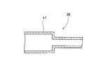
絞り部20は作動液の流量を減流できれば絞り弁に限定されない。たとえば、図3のように第1ラインL1の口径を狭めて絞り部20としてもよいし、図4のように第1ラインL1の中に設けられた板体30などで口径を狭めて絞り部20としてもよい。
The throttle portion 20 is not limited to the throttle valve as long as the flow rate of the working fluid can be reduced. For example, as shown in FIG. 3, the diameter of the first line L1 may be narrowed to form the throttle portion 20, or as shown in FIG. 4, a plate body 30 provided in the first line L1 may be narrowed in diameter to form the throttle portion 20. It may be 20.
[圧力計]
第1ラインL1における絞り部20の上流の作動液の圧力が第1圧力計22で測定される。絞り部20の上流は、第1ラインL1における絞り部20よりも優先分流弁12側である。第1ラインL1における絞り部20の下流の作動液の圧力が第2圧力計24で測定する。絞り部20の下流は、第1ラインL1における絞り部20よりもポートPF側である。第1圧力計22および第2圧力計24はブルドン管圧力計またはダイアフラム式圧力計などを使用できるが、作動油の圧力が計測できれば第1圧力計22および第2圧力計24は特に限定されない。 [Pressure gauge]
The pressure of the hydraulic fluid upstream of thethrottle portion 20 in the first line L1 is measured by the first pressure gauge 22. The upstream of the throttle portion 20 is on the priority distribution valve 12 side of the throttle portion 20 in the first line L1. The pressure of the working fluid downstream of the throttle portion 20 in the first line L1 is measured by the second pressure gauge 24. The downstream side of the throttle portion 20 is on the port PF side of the throttle portion 20 in the first line L1. The first pressure gauge 22 and the second pressure gauge 24 can use a Bourdon tube pressure gauge, a diaphragm type pressure gauge, or the like, but the first pressure gauge 22 and the second pressure gauge 24 are not particularly limited as long as the pressure of the hydraulic oil can be measured.
第1ラインL1における絞り部20の上流の作動液の圧力が第1圧力計22で測定される。絞り部20の上流は、第1ラインL1における絞り部20よりも優先分流弁12側である。第1ラインL1における絞り部20の下流の作動液の圧力が第2圧力計24で測定する。絞り部20の下流は、第1ラインL1における絞り部20よりもポートPF側である。第1圧力計22および第2圧力計24はブルドン管圧力計またはダイアフラム式圧力計などを使用できるが、作動油の圧力が計測できれば第1圧力計22および第2圧力計24は特に限定されない。 [Pressure gauge]
The pressure of the hydraulic fluid upstream of the
[制御部]
制御部26に第1圧力計22の圧力値および第2圧力計24の圧力値が入力され、制御部26はそれらの圧力値を用いて作動液に異物が混入されていることを判断する。制御部26はICなどの小型のコンピュータを用いる。フォークリフト18に搭載されたコンピュータが制御部26として利用されても良い。制御部26は第1圧力計22と第2圧力計24で測定された圧力値の差を取り、その差が上記一定範囲内であれば作動液に異常がなく、一定範囲を超えれば作動液に異常(異物の混入)があると判断する。 [Control unit]
The pressure value of thefirst pressure gauge 22 and the pressure value of the second pressure gauge 24 are input to the control unit 26, and the control unit 26 determines that foreign matter is mixed in the working fluid using these pressure values. The control unit 26 uses a small computer such as an IC. The computer mounted on the forklift 18 may be used as the control unit 26. The control unit 26 takes the difference between the pressure values measured by the first pressure gauge 22 and the second pressure gauge 24, and if the difference is within the above-mentioned certain range, there is no abnormality in the working fluid, and if the difference exceeds the certain range, the working fluid is normal. It is judged that there is an abnormality (mixture of foreign matter) in.
制御部26に第1圧力計22の圧力値および第2圧力計24の圧力値が入力され、制御部26はそれらの圧力値を用いて作動液に異物が混入されていることを判断する。制御部26はICなどの小型のコンピュータを用いる。フォークリフト18に搭載されたコンピュータが制御部26として利用されても良い。制御部26は第1圧力計22と第2圧力計24で測定された圧力値の差を取り、その差が上記一定範囲内であれば作動液に異常がなく、一定範囲を超えれば作動液に異常(異物の混入)があると判断する。 [Control unit]
The pressure value of the
制御部26で作動油に異常があると判断した場合にフォークリフト18の任意の場所で表示したり、音声出力したりすることが好ましい。フォークリフト18の操作者に異常を知らせる。
When the control unit 26 determines that there is an abnormality in the hydraulic oil, it is preferable to display it at an arbitrary place on the forklift 18 or output a voice. Notify the operator of the forklift 18 of the abnormality.
[その他]
第2ラインL2と並列に第3ラインL3が設けられている。第3ラインL3は、第1ラインL1と第2ラインL2とに圧力制御弁32、34を介して接続されている。第1ラインL1と第2ラインL2は、そのラインL1、L2の作動液の圧力が一定以上になると、圧力制御弁32、34が開けられ、作動液が第3ラインL3に流される。第1ラインL1と第2ラインL2の作動液の圧力が一定値を下回るようになっている。優先分流弁12と圧力制御弁32との間に絞り弁36を設け、圧力制御弁32への作動液の流量を調整してもよい。 [Other]
A third line L3 is provided in parallel with the second line L2. The third line L3 is connected to the first line L1 and the second line L2 via pressure control valves 32 and 34. In the first line L1 and the second line L2, when the pressure of the hydraulic fluid in the lines L1 and L2 exceeds a certain level, the pressure control valves 32 and 34 are opened and the hydraulic fluid is flowed to the third line L3. The pressure of the working fluids of the first line L1 and the second line L2 falls below a certain value. A throttle valve 36 may be provided between the priority shunt valve 12 and the pressure control valve 32 to adjust the flow rate of the hydraulic fluid to the pressure control valve 32.
第2ラインL2と並列に第3ラインL3が設けられている。第3ラインL3は、第1ラインL1と第2ラインL2とに圧力制御弁32、34を介して接続されている。第1ラインL1と第2ラインL2は、そのラインL1、L2の作動液の圧力が一定以上になると、圧力制御弁32、34が開けられ、作動液が第3ラインL3に流される。第1ラインL1と第2ラインL2の作動液の圧力が一定値を下回るようになっている。優先分流弁12と圧力制御弁32との間に絞り弁36を設け、圧力制御弁32への作動液の流量を調整してもよい。 [Other]
A third line L3 is provided in parallel with the second line L2. The third line L3 is connected to the first line L1 and the second line L2 via
[異常判断方法]
ステアリング28が操作されているときは優先分流弁12によって作動液の優先流が第1ラインL1に流され、余剰流が第2ラインL2に流される。絞り部20の上流の作動液の圧力が第1圧力計22で計測され、絞り部20の下流の作動液の圧力が第2圧力計24で計測される。計測された圧力値の差が一定範囲に入っていれば、制御部26は多連バルブ装置10の中に異物が混入していないと判断する。制御部26は計測された圧力値の差が一定範囲よりも大きくなれば多連バルブ装置10の中に異物が混入していると判断する。早期に作動液を交換し、フォークリフト18が異常停止しないようにする。 [Abnormality judgment method]
When thesteering 28 is operated, the priority flow valve 12 causes the priority flow of the hydraulic fluid to flow to the first line L1 and the excess flow to the second line L2. The pressure of the hydraulic fluid upstream of the throttle portion 20 is measured by the first pressure gauge 22, and the pressure of the hydraulic fluid downstream of the throttle portion 20 is measured by the second pressure gauge 24. If the difference between the measured pressure values is within a certain range, the control unit 26 determines that no foreign matter is mixed in the multiple valve device 10. If the difference between the measured pressure values becomes larger than a certain range, the control unit 26 determines that foreign matter is mixed in the multiple valve device 10. Replace the hydraulic fluid at an early stage so that the forklift 18 does not stop abnormally.
ステアリング28が操作されているときは優先分流弁12によって作動液の優先流が第1ラインL1に流され、余剰流が第2ラインL2に流される。絞り部20の上流の作動液の圧力が第1圧力計22で計測され、絞り部20の下流の作動液の圧力が第2圧力計24で計測される。計測された圧力値の差が一定範囲に入っていれば、制御部26は多連バルブ装置10の中に異物が混入していないと判断する。制御部26は計測された圧力値の差が一定範囲よりも大きくなれば多連バルブ装置10の中に異物が混入していると判断する。早期に作動液を交換し、フォークリフト18が異常停止しないようにする。 [Abnormality judgment method]
When the
以上のように、本願は優先的に作動液が流れている第1ラインL1に絞り部20を設けることで、異物が絞り部20に引っかかった場合に絞り部20の上流と下流の圧力差が大きくなることを利用して、作動油の中に異物が入っていることを判断できる。従来と異なり、作動油の中の異物を検知できる。早期に異常を発見して解消できるため、フォークリフト18を停止させることが少なくなる。絞り部20はステアリング28への作動液の流れを止めることはなく、ステアリング操作に影響はない。
As described above, in the present application, by providing the throttle portion 20 in the first line L1 in which the hydraulic fluid is preferentially flowing, the pressure difference between the upstream and the downstream of the throttle portion 20 is increased when a foreign substance is caught in the throttle portion 20. It can be determined that foreign matter is contained in the hydraulic oil by using the increase in size. Unlike the conventional method, foreign matter in the hydraulic oil can be detected. Since the abnormality can be detected and resolved at an early stage, the forklift 18 is less likely to be stopped. The throttle portion 20 does not stop the flow of the hydraulic fluid to the steering 28 and does not affect the steering operation.
[実施形態2]
図5の多連バルブ装置50のように、第2ラインL2に絞り部20、第1圧力計22および第2圧力計24を設けても良い。第2ラインL2における優先分流弁12と方向制御弁14との間に絞り部20を設ける。第1圧力計22は第2ラインL2における絞り部20の上流の作動液の圧力、第2圧力計24は第2ラインL2における絞り部20の下流の作動液の圧力を計測する。制御部26は、上記実施形態と同様に第1圧力計22と第2圧力計24で計測された圧力値の差を利用して異常を判断する。 [Embodiment 2]
As in themultiple valve device 50 of FIG. 5, the throttle portion 20, the first pressure gauge 22, and the second pressure gauge 24 may be provided on the second line L2. A throttle portion 20 is provided between the priority diversion valve 12 and the directional control valve 14 in the second line L2. The first pressure gauge 22 measures the pressure of the hydraulic fluid upstream of the throttle portion 20 in the second line L2, and the second pressure gauge 24 measures the pressure of the hydraulic fluid downstream of the throttle portion 20 in the second line L2. The control unit 26 determines an abnormality by using the difference between the pressure values measured by the first pressure gauge 22 and the second pressure gauge 24 as in the above embodiment.
図5の多連バルブ装置50のように、第2ラインL2に絞り部20、第1圧力計22および第2圧力計24を設けても良い。第2ラインL2における優先分流弁12と方向制御弁14との間に絞り部20を設ける。第1圧力計22は第2ラインL2における絞り部20の上流の作動液の圧力、第2圧力計24は第2ラインL2における絞り部20の下流の作動液の圧力を計測する。制御部26は、上記実施形態と同様に第1圧力計22と第2圧力計24で計測された圧力値の差を利用して異常を判断する。 [Embodiment 2]
As in the
図6の多連バルブ装置60のように、絞り部20が第1ラインL1と第2ラインL2の両方に設けられ、それぞれの上流と下流の作動油の圧力が第1圧力計22と第2圧力計24で計測されてもよい。各ラインL1、L2の絞り部20の上流と下流の圧力差を利用して異常を判断する。絞り部20が多くなることで異常を検出しやすい。
As in the multiple valve device 60 of FIG. 6, throttle portions 20 are provided in both the first line L1 and the second line L2, and the pressures of the hydraulic oils upstream and downstream of each are the pressure gauges 22 and the second. It may be measured by the pressure gauge 24. An abnormality is determined by using the pressure difference between the upstream and downstream of the throttle portion 20 of each line L1 and L2. Since the number of diaphragms 20 is increased, it is easy to detect an abnormality.
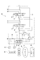
[実施形態3]
図7の多連バルブ装置70のように、第1圧力計22のみを使用して異物を検知しても良い。この場合、制御部26はステアリング28を制御するステアリング制御装置72からステアリング28の情報を得るようにする。ステアリング28の情報はステアリング28の角度を含む。ステアリング28の角度によって絞り部20の下流の作動液の圧力がわかる。制御部26はステアリング28の角度に応じた絞り部20の下流の圧力を記憶部(図示省略)に記憶しておく。制御部26は第1圧力計22から得られた圧力とステアリング28の角度に応じた圧力の差をとって異常を判断する。 [Embodiment 3]
As in themultiple valve device 70 of FIG. 7, foreign matter may be detected using only the first pressure gauge 22. In this case, the control unit 26 obtains information on the steering wheel 28 from the steering control device 72 that controls the steering wheel 28. The information on the steering 28 includes the angle of the steering 28. The pressure of the hydraulic fluid downstream of the throttle portion 20 can be known from the angle of the steering 28. The control unit 26 stores the pressure downstream of the throttle unit 20 according to the angle of the steering 28 in a storage unit (not shown). The control unit 26 determines an abnormality by taking the difference between the pressure obtained from the first pressure gauge 22 and the pressure according to the angle of the steering wheel 28.
図7の多連バルブ装置70のように、第1圧力計22のみを使用して異物を検知しても良い。この場合、制御部26はステアリング28を制御するステアリング制御装置72からステアリング28の情報を得るようにする。ステアリング28の情報はステアリング28の角度を含む。ステアリング28の角度によって絞り部20の下流の作動液の圧力がわかる。制御部26はステアリング28の角度に応じた絞り部20の下流の圧力を記憶部(図示省略)に記憶しておく。制御部26は第1圧力計22から得られた圧力とステアリング28の角度に応じた圧力の差をとって異常を判断する。 [Embodiment 3]
As in the
[実施形態4]
図8のように通信部82が備えられた多連バルブ装置80であってもよい。制御部26で取得した圧力値をネットワーク84を介してホストコンピュータ86に送信する。通信部82はネットワーク84を介して移動体通信をおこなえる装置、WiFiなどの無線通信する装置などが挙げられる。測定した値を通信部82によって送信し、ホストコンピュータ86の記憶手段で記憶する。また、制御部26がおこなう異常の判断をホストコンピュータ86で行ってもよい。ホストコンピュータ86で判断された結果をネットワーク84を介して操作者が使用するフォークリフト18で表示してもよい。図5から図7の多連バルブ装置50、60、70においても図8と同じように通信部82、ネットワーク84、ホストコンピュータ86を備えた構成であってもよい。 [Embodiment 4]
As shown in FIG. 8, themulti-valve device 80 provided with the communication unit 82 may be used. The pressure value acquired by the control unit 26 is transmitted to the host computer 86 via the network 84. Examples of the communication unit 82 include a device capable of performing mobile communication via the network 84, a device for wireless communication such as WiFi, and the like. The measured value is transmitted by the communication unit 82 and stored in the storage means of the host computer 86. Further, the host computer 86 may determine the abnormality performed by the control unit 26. The result determined by the host computer 86 may be displayed by the forklift 18 used by the operator via the network 84. The multiple valve devices 50, 60, and 70 of FIGS. 5 to 7 may also have a configuration in which the communication unit 82, the network 84, and the host computer 86 are provided as in FIG.
図8のように通信部82が備えられた多連バルブ装置80であってもよい。制御部26で取得した圧力値をネットワーク84を介してホストコンピュータ86に送信する。通信部82はネットワーク84を介して移動体通信をおこなえる装置、WiFiなどの無線通信する装置などが挙げられる。測定した値を通信部82によって送信し、ホストコンピュータ86の記憶手段で記憶する。また、制御部26がおこなう異常の判断をホストコンピュータ86で行ってもよい。ホストコンピュータ86で判断された結果をネットワーク84を介して操作者が使用するフォークリフト18で表示してもよい。図5から図7の多連バルブ装置50、60、70においても図8と同じように通信部82、ネットワーク84、ホストコンピュータ86を備えた構成であってもよい。 [Embodiment 4]
As shown in FIG. 8, the
[実施形態5]
多連バルブ装置はフォークリフト18の構成によって種々に変更されてもよく、上記した実施形態の多連バルブ装置に限定されない。たとえば、方向制御弁14、16の数は3つ以上になってもよい。たとえば、フォークNLを左右に動かすためのシリンダを備えれば、そのシリンダに作動液を供給するための方向制御弁を追加する。 [Embodiment 5]
The multiple valve device may be variously changed depending on the configuration of theforklift 18, and is not limited to the multiple valve device of the above-described embodiment. For example, the number of directional control valves 14 and 16 may be three or more. For example, if a cylinder for moving the fork NL to the left or right is provided, a directional control valve for supplying the hydraulic fluid to the cylinder is added.
多連バルブ装置はフォークリフト18の構成によって種々に変更されてもよく、上記した実施形態の多連バルブ装置に限定されない。たとえば、方向制御弁14、16の数は3つ以上になってもよい。たとえば、フォークNLを左右に動かすためのシリンダを備えれば、そのシリンダに作動液を供給するための方向制御弁を追加する。 [Embodiment 5]
The multiple valve device may be variously changed depending on the configuration of the
荷役装置としてフォークリフト18を用いて説明したが、説明した多連バルブ装置が使用される荷役装置であればフォークリフト18に限定されない。
Although the forklift 18 has been described as the cargo handling device, the cargo handling device is not limited to the forklift 18 as long as the multiple valve device described above is used.
(第1項)本願の多連バルブ装置は、作動液を優先流と余剰流に分流して吐出する優先分流弁と、前記優先流が流れる第1ラインと、前記余剰流が流れる第2ラインと、前記第1ラインおよび第2ラインの少なくとも一方に設けられた絞り部と、前記第1ラインおよび第2ラインにおいて、前記絞り部の上流側における作動液の圧力を計測する第1圧力計と、前記第1圧力計の圧力値から作動液の中に異物が混入していることを判断する制御部とを備える。
(Clause 1) In the multiple valve device of the present application, a priority diversion valve that divides and discharges the hydraulic fluid into a priority flow and a surplus flow, a first line through which the priority flow flows, and a second line through which the surplus flow flows. And a throttle portion provided on at least one of the first line and the second line, and a first pressure gauge for measuring the pressure of the hydraulic fluid on the upstream side of the throttle portion in the first line and the second line. A control unit for determining whether foreign matter is mixed in the working fluid from the pressure value of the first pressure gauge is provided.
第1項に記載する多連バルブ装置によると、絞り部に異物が引っかかることで第1圧力計の圧力値が上昇し、制御部が異常を判断できる。従来できなかった油圧回路の中の異常を判断でき、荷役装置の停止を防止できる。
According to the multiple valve device described in item 1, the pressure value of the first pressure gauge rises due to foreign matter being caught in the throttle portion, and the control unit can determine an abnormality. It is possible to determine an abnormality in the hydraulic circuit, which was not possible in the past, and prevent the cargo handling device from stopping.
(第2項)前記第1ラインおよび第2ラインにおいて、前記絞り部の下流側における作動液の圧力を計測する第2圧力計を備え、前記制御部が第1圧力計の圧力値と第2圧力計の圧力値から作動液の中に異物が混入していることを判断する。
(Item 2) In the first line and the second line, a second pressure gauge for measuring the pressure of the hydraulic fluid on the downstream side of the throttle portion is provided, and the control unit has a pressure value of the first pressure gauge and a second. Judge that foreign matter is mixed in the working fluid from the pressure value of the pressure gauge.
第2項に記載する多連バルブ装置によると、絞り部に異物が引っかかることで絞り部の上流と下流の作動液の圧力差が大きくなることを利用して異常を判断できる。
According to the multiple valve device described in the second item, an abnormality can be determined by utilizing the fact that the pressure difference between the hydraulic fluid upstream and downstream of the throttle portion becomes large due to foreign matter being caught in the throttle portion.
(第3項)前記制御部は、第1圧力計の圧力値と第2圧力計の圧力値との差が一定範囲よりも大きくなった場合、異物が作動液に混入されていると判断する。
(Item 3) When the difference between the pressure value of the first pressure gauge and the pressure value of the second pressure gauge becomes larger than a certain range, the control unit determines that foreign matter is mixed in the working fluid. ..
第3項に記載する多連バルブ装置によると、作動液中の異物が多くなってくると徐々に圧力値の差が大きくなってくるため、異物によって多連バルブ装置が停止する前に、多連バルブ装置を修理できる。
According to the multi-valve device described in the third item, as the amount of foreign matter in the working fluid increases, the difference in pressure value gradually increases. The continuous valve device can be repaired.
(第4項)本願の荷役装置は、第1項から第3項に記載する多連バルブ装置を備える。
(Section 4) The cargo handling device of the present application includes the multiple valve device described in paragraphs 1 to 3.
第4項に記載する荷役装置は、上記の多連バルブ装置を使用しているため、多連バルブ装置の停止を予防できるため、荷役装置の停止を予防できる。
Since the cargo handling device described in paragraph 4 uses the above-mentioned multiple valve device, the stop of the multiple valve device can be prevented, so that the stop of the cargo handling device can be prevented.
その他、本発明は、その主旨を逸脱しない範囲で当業者の知識に基づき種々の改良、修正、変更を加えた態様で実施できるものである。
In addition, the present invention can be carried out in a mode in which various improvements, modifications and changes are made based on the knowledge of those skilled in the art without departing from the gist thereof.
10、50、60、70、80:多連バルブ装置
12:優先分流弁
14、16:方向制御弁
18:フォークリフト(荷役装置)
20:絞り部
22、24:圧力計
26:制御部
28:ステアリング
30:板体
32、34:圧力制御弁
36:絞り弁
72:ステアリング制御装置
82:通信部
84:ネットワーク
86:ホストコンピュータ
PF、X、A1、A2、A3、P、T:ポート
L1、L2、L3:ライン
LL、TL:レバー
LS、TS:シリンダ
NF:フォーク
MT:マスト 10, 50, 60, 70, 80: Multiple valve device 12:Priority diversion valve 14, 16: Direction control valve 18: Forklift (cargo handling device)
20: Squeezingunit 22, 24: Pressure gauge 26: Control unit 28: Steering 30: Plate 32, 34: Pressure control valve 36: Squeezing valve 72: Steering control device 82: Communication unit 84: Network 86: Host computer PF, X, A1, A2, A3, P, T: Port L1, L2, L3: Line LL, TL: Lever LS, TS: Cylinder NF: Fork MT: Mast
12:優先分流弁
14、16:方向制御弁
18:フォークリフト(荷役装置)
20:絞り部
22、24:圧力計
26:制御部
28:ステアリング
30:板体
32、34:圧力制御弁
36:絞り弁
72:ステアリング制御装置
82:通信部
84:ネットワーク
86:ホストコンピュータ
PF、X、A1、A2、A3、P、T:ポート
L1、L2、L3:ライン
LL、TL:レバー
LS、TS:シリンダ
NF:フォーク
MT:マスト 10, 50, 60, 70, 80: Multiple valve device 12:
20: Squeezing
Claims (4)
- 作動液を優先流と余剰流に分流して吐出する優先分流弁と、
前記優先流が流れる第1ラインと、
前記余剰流が流れる第2ラインと、
前記第1ラインおよび第2ラインの少なくとも一方に設けられた絞り部と、
前記第1ラインおよび第2ラインにおいて、前記絞り部の上流側における作動液の圧力を計測する第1圧力計と、
前記第1圧力計の圧力値から作動液の中に異物が混入していることを判断する制御部と、
を備えた多連バルブ装置。 A priority divergence valve that divides the hydraulic fluid into a priority flow and a surplus flow and discharges them.
The first line through which the priority flow flows and
The second line through which the excess flow flows and
A diaphragm portion provided on at least one of the first line and the second line, and
In the first line and the second line, a first pressure gauge for measuring the pressure of the hydraulic fluid on the upstream side of the throttle portion, and a first pressure gauge.
A control unit that determines from the pressure value of the first pressure gauge that foreign matter is mixed in the working fluid, and
Multi-valve device with. - 前記第1ラインおよび第2ラインにおいて、前記絞り部の下流側における作動液の圧力を計測する第2圧力計を備え、
前記制御部が第1圧力計の圧力値と第2圧力計の圧力値から作動液の中に異物が混入していることを判断する請求項1の多連バルブ装置。 In the first line and the second line, a second pressure gauge for measuring the pressure of the hydraulic fluid on the downstream side of the throttle portion is provided.
The multiple valve device according to claim 1, wherein the control unit determines from the pressure value of the first pressure gauge and the pressure value of the second pressure gauge that foreign matter is mixed in the working fluid. - 前記制御部は、第1圧力計の圧力値と第2圧力計の圧力値との差が一定範囲よりも大きくなった場合、異物が作動液に混入されていると判断する請求項2の多連バルブ装置。 When the difference between the pressure value of the first pressure gauge and the pressure value of the second pressure gauge becomes larger than a certain range, the control unit determines that foreign matter is mixed in the working fluid. Ream valve device.
- 請求項3の多連バルブ装置を備えた荷役装置。 A cargo handling device including the multiple valve device according to claim 3.
Priority Applications (2)
| Application Number | Priority Date | Filing Date | Title |
|---|---|---|---|
| JP2021543846A JP7248131B2 (en) | 2019-09-03 | 2019-09-03 | Multiple valve device and cargo handling equipment provided with the multiple valve device |
| PCT/JP2019/034646 WO2021044526A1 (en) | 2019-09-03 | 2019-09-03 | Multiple valve device and cargo handling device equipped with multiple valve device |
Applications Claiming Priority (1)
| Application Number | Priority Date | Filing Date | Title |
|---|---|---|---|
| PCT/JP2019/034646 WO2021044526A1 (en) | 2019-09-03 | 2019-09-03 | Multiple valve device and cargo handling device equipped with multiple valve device |
Publications (1)
| Publication Number | Publication Date |
|---|---|
| WO2021044526A1 true WO2021044526A1 (en) | 2021-03-11 |
Family
ID=74852350
Family Applications (1)
| Application Number | Title | Priority Date | Filing Date |
|---|---|---|---|
| PCT/JP2019/034646 WO2021044526A1 (en) | 2019-09-03 | 2019-09-03 | Multiple valve device and cargo handling device equipped with multiple valve device |
Country Status (2)
| Country | Link |
|---|---|
| JP (1) | JP7248131B2 (en) |
| WO (1) | WO2021044526A1 (en) |
Citations (5)
| Publication number | Priority date | Publication date | Assignee | Title |
|---|---|---|---|---|
| JPS62105318U (en) * | 1985-12-23 | 1987-07-04 | ||
| JPH02227110A (en) * | 1989-02-28 | 1990-09-10 | Komatsu Ltd | Indicator for degree of contamination in hydraulic pressure circuit |
| JPH0651508U (en) * | 1991-11-18 | 1994-07-15 | 株式会社新潟鉄工所 | Filter clogging alarm device |
| JP2003095121A (en) * | 2001-09-25 | 2003-04-03 | Kayaba Ind Co Ltd | Hydraulic control device for vehicle |
| JP2003130012A (en) * | 2001-10-26 | 2003-05-08 | Shimadzu Corp | Liquid pressure controlling device |
-
2019
- 2019-09-03 WO PCT/JP2019/034646 patent/WO2021044526A1/en active Application Filing
- 2019-09-03 JP JP2021543846A patent/JP7248131B2/en active Active
Patent Citations (5)
| Publication number | Priority date | Publication date | Assignee | Title |
|---|---|---|---|---|
| JPS62105318U (en) * | 1985-12-23 | 1987-07-04 | ||
| JPH02227110A (en) * | 1989-02-28 | 1990-09-10 | Komatsu Ltd | Indicator for degree of contamination in hydraulic pressure circuit |
| JPH0651508U (en) * | 1991-11-18 | 1994-07-15 | 株式会社新潟鉄工所 | Filter clogging alarm device |
| JP2003095121A (en) * | 2001-09-25 | 2003-04-03 | Kayaba Ind Co Ltd | Hydraulic control device for vehicle |
| JP2003130012A (en) * | 2001-10-26 | 2003-05-08 | Shimadzu Corp | Liquid pressure controlling device |
Also Published As
| Publication number | Publication date |
|---|---|
| JP7248131B2 (en) | 2023-03-29 |
| JPWO2021044526A1 (en) | 2021-03-11 |
Similar Documents
| Publication | Publication Date | Title |
|---|---|---|
| JP5769725B2 (en) | Recalibration of out-of-range sensors | |
| US11572670B2 (en) | Hydraulic control arrangement for an arrangement of mobile machines, and arrangement of mobile machines | |
| US11073171B2 (en) | Hydraulic system | |
| US8528460B2 (en) | Hydraulic valve arrangement | |
| US8428823B2 (en) | Steering control device and steering control method for working vehicle | |
| CN105008626A (en) | Merging circuit of hydraulic apparatus | |
| US11118607B2 (en) | Variable hydraulic pressure relief systems and methods for a material handling vehicle | |
| CN108622805A (en) | The system and method stablized for materials handling vehicle upper mast | |
| KR20100016316A (en) | Hydraulic load control valve device | |
| US6314997B1 (en) | Multiple valve apparatus | |
| WO2021044526A1 (en) | Multiple valve device and cargo handling device equipped with multiple valve device | |
| EP2282064B1 (en) | Open center hydraulic system | |
| JP4900671B2 (en) | Electronic control valve calibration device | |
| US11377334B2 (en) | Industrial truck with at least one hydraulic mast lift cylinder | |
| EP2005006B1 (en) | Pilot-operated differential-area pressure compensator and control system for piloting same | |
| GB2534518A (en) | Hydraulic drive system | |
| JP2007153610A (en) | Control circuit for forklift | |
| WO2021084784A1 (en) | Failure diagnostic system and failure diagnostic method | |
| JP2004517016A (en) | Control device for actuation device connected to hydraulic circuit | |
| JPH05172107A (en) | Capacity control device for variable hydraulic pump | |
| CN111503071A (en) | Hydraulic drive device for industrial vehicle | |
| WO2020194528A1 (en) | Failure diagnostic system and failure diagnostic method | |
| KR200454928Y1 (en) | Hydraulic control unit to improve the handleability of forklift | |
| KR20190086988A (en) | Cooling Fan-Brake System and Method of Controlling Brake Charging using the Same | |
| US20240068492A1 (en) | Calibration system and calibration method in hydraulic system |
Legal Events
| Date | Code | Title | Description |
|---|---|---|---|
| 121 | Ep: the epo has been informed by wipo that ep was designated in this application |
Ref document number: 19944205 Country of ref document: EP Kind code of ref document: A1 |
|
| ENP | Entry into the national phase |
Ref document number: 2021543846 Country of ref document: JP Kind code of ref document: A |
|
| NENP | Non-entry into the national phase |
Ref country code: DE |
|
| 122 | Ep: pct application non-entry in european phase |
Ref document number: 19944205 Country of ref document: EP Kind code of ref document: A1 |