WO2021039989A1 - Leaning vehicle - Google Patents
Leaning vehicle Download PDFInfo
- Publication number
- WO2021039989A1 WO2021039989A1 PCT/JP2020/032675 JP2020032675W WO2021039989A1 WO 2021039989 A1 WO2021039989 A1 WO 2021039989A1 JP 2020032675 W JP2020032675 W JP 2020032675W WO 2021039989 A1 WO2021039989 A1 WO 2021039989A1
- Authority
- WO
- WIPO (PCT)
- Prior art keywords
- lean vehicle
- body frame
- main skeleton
- vehicle body
- vehicle
- Prior art date
Links
Images


Classifications
-
- B—PERFORMING OPERATIONS; TRANSPORTING
- B62—LAND VEHICLES FOR TRAVELLING OTHERWISE THAN ON RAILS
- B62K—CYCLES; CYCLE FRAMES; CYCLE STEERING DEVICES; RIDER-OPERATED TERMINAL CONTROLS SPECIALLY ADAPTED FOR CYCLES; CYCLE AXLE SUSPENSIONS; CYCLE SIDE-CARS, FORECARS, OR THE LIKE
- B62K5/00—Cycles with handlebars, equipped with three or more main road wheels
- B62K5/10—Cycles with handlebars, equipped with three or more main road wheels with means for inwardly inclining the vehicle body on bends
-
- B—PERFORMING OPERATIONS; TRANSPORTING
- B62—LAND VEHICLES FOR TRAVELLING OTHERWISE THAN ON RAILS
- B62J—CYCLE SADDLES OR SEATS; AUXILIARY DEVICES OR ACCESSORIES SPECIALLY ADAPTED TO CYCLES AND NOT OTHERWISE PROVIDED FOR, e.g. ARTICLE CARRIERS OR CYCLE PROTECTORS
- B62J17/00—Weather guards for riders; Fairings or stream-lining parts not otherwise provided for
- B62J17/08—Hoods protecting the rider
- B62J17/086—Frame mounted hoods specially adapted for motorcycles or the like
-
- B—PERFORMING OPERATIONS; TRANSPORTING
- B62—LAND VEHICLES FOR TRAVELLING OTHERWISE THAN ON RAILS
- B62J—CYCLE SADDLES OR SEATS; AUXILIARY DEVICES OR ACCESSORIES SPECIALLY ADAPTED TO CYCLES AND NOT OTHERWISE PROVIDED FOR, e.g. ARTICLE CARRIERS OR CYCLE PROTECTORS
- B62J25/00—Foot-rests; Knee grips; Passenger hand-grips
- B62J25/04—Floor-type foot rests
-
- B—PERFORMING OPERATIONS; TRANSPORTING
- B62—LAND VEHICLES FOR TRAVELLING OTHERWISE THAN ON RAILS
- B62K—CYCLES; CYCLE FRAMES; CYCLE STEERING DEVICES; RIDER-OPERATED TERMINAL CONTROLS SPECIALLY ADAPTED FOR CYCLES; CYCLE AXLE SUSPENSIONS; CYCLE SIDE-CARS, FORECARS, OR THE LIKE
- B62K5/00—Cycles with handlebars, equipped with three or more main road wheels
- B62K5/02—Tricycles
- B62K5/05—Tricycles characterised by a single rear wheel
-
- B—PERFORMING OPERATIONS; TRANSPORTING
- B62—LAND VEHICLES FOR TRAVELLING OTHERWISE THAN ON RAILS
- B62K—CYCLES; CYCLE FRAMES; CYCLE STEERING DEVICES; RIDER-OPERATED TERMINAL CONTROLS SPECIALLY ADAPTED FOR CYCLES; CYCLE AXLE SUSPENSIONS; CYCLE SIDE-CARS, FORECARS, OR THE LIKE
- B62K5/00—Cycles with handlebars, equipped with three or more main road wheels
- B62K5/02—Tricycles
- B62K5/06—Frames for tricycles
-
- B—PERFORMING OPERATIONS; TRANSPORTING
- B62—LAND VEHICLES FOR TRAVELLING OTHERWISE THAN ON RAILS
- B62K—CYCLES; CYCLE FRAMES; CYCLE STEERING DEVICES; RIDER-OPERATED TERMINAL CONTROLS SPECIALLY ADAPTED FOR CYCLES; CYCLE AXLE SUSPENSIONS; CYCLE SIDE-CARS, FORECARS, OR THE LIKE
- B62K5/00—Cycles with handlebars, equipped with three or more main road wheels
- B62K5/08—Cycles with handlebars, equipped with three or more main road wheels with steering devices acting on two or more wheels
-
- B—PERFORMING OPERATIONS; TRANSPORTING
- B60—VEHICLES IN GENERAL
- B60G—VEHICLE SUSPENSION ARRANGEMENTS
- B60G2200/00—Indexing codes relating to suspension types
- B60G2200/10—Independent suspensions
- B60G2200/14—Independent suspensions with lateral arms
- B60G2200/144—Independent suspensions with lateral arms with two lateral arms forming a parallelogram
-
- B—PERFORMING OPERATIONS; TRANSPORTING
- B60—VEHICLES IN GENERAL
- B60G—VEHICLE SUSPENSION ARRANGEMENTS
- B60G2300/00—Indexing codes relating to the type of vehicle
- B60G2300/12—Cycles; Motorcycles
- B60G2300/122—Trikes
-
- B—PERFORMING OPERATIONS; TRANSPORTING
- B60—VEHICLES IN GENERAL
- B60G—VEHICLE SUSPENSION ARRANGEMENTS
- B60G2300/00—Indexing codes relating to the type of vehicle
- B60G2300/45—Rolling frame vehicles
-
- B—PERFORMING OPERATIONS; TRANSPORTING
- B62—LAND VEHICLES FOR TRAVELLING OTHERWISE THAN ON RAILS
- B62K—CYCLES; CYCLE FRAMES; CYCLE STEERING DEVICES; RIDER-OPERATED TERMINAL CONTROLS SPECIALLY ADAPTED FOR CYCLES; CYCLE AXLE SUSPENSIONS; CYCLE SIDE-CARS, FORECARS, OR THE LIKE
- B62K11/00—Motorcycles, engine-assisted cycles or motor scooters with one or two wheels
- B62K11/02—Frames
- B62K11/04—Frames characterised by the engine being between front and rear wheels
-
- B—PERFORMING OPERATIONS; TRANSPORTING
- B62—LAND VEHICLES FOR TRAVELLING OTHERWISE THAN ON RAILS
- B62K—CYCLES; CYCLE FRAMES; CYCLE STEERING DEVICES; RIDER-OPERATED TERMINAL CONTROLS SPECIALLY ADAPTED FOR CYCLES; CYCLE AXLE SUSPENSIONS; CYCLE SIDE-CARS, FORECARS, OR THE LIKE
- B62K5/00—Cycles with handlebars, equipped with three or more main road wheels
- B62K2005/001—Suspension details for cycles with three or more main road wheels
Definitions
- the present invention relates to a lean vehicle.
- Patent Document 1 discloses a three-wheel tilting vehicle having a body frame, two front wheels, and one rear wheel.
- the two front wheels include a left front wheel and a right front wheel.
- An object of the present invention is to provide a lean vehicle capable of increasing the degree of freedom in designing a lean vehicle, including the degree of freedom in the riding position of the driver and the layout of mounted parts mounted on the vehicle body frame.
- the lean vehicle includes a vehicle body frame, a seat supported by the vehicle body frame and seated by the driver, and a left step and a right step supported by the vehicle body frame on which the driver puts his / her feet.
- the vehicle body frame includes a main skeleton portion.
- the front part of the main skeleton located in front of the center of the left step and the right step in the front-rear direction in the main skeleton extends linearly in the front-rear direction, and the dimension of the front part of the main skeleton in the vehicle width direction is said.
- At least a part of the tilted link mechanism is supported at a position below the upper surface of at least a part of the right step.
- the front part of the main skeleton extends linearly in the front-rear direction, and the dimensions of the front part of the main skeleton in the vehicle width direction are the support portion of the left swing arm with respect to the vehicle body frame and the right swing arm with respect to the vehicle body frame.
- At least a part of the tilted link mechanism at a position below the upper surface of at least a part of the left step and the right step in the side view of the lean vehicle which is configured to be larger than the distance from the support portion of the vehicle.
- the lean vehicle of the present invention preferably includes the following configurations.
- the main skeleton portion is located between the left step and the right step in a plan view.
- the degree of freedom in the driver's riding position and the layout of the mounted parts mounted on the vehicle body frame is increased. Can be done. Therefore, the degree of freedom in designing the lean vehicle can be increased.
- the lean vehicle of the present invention preferably includes the following configurations.
- the main skeleton portion extends linearly in the front-rear direction between both legs of the driver when the driver puts his / her feet on the left step and the right step while the driver is seated on the seat.
- the main skeleton has a narrow width and a shape that extends linearly in the front-rear direction.
- the lean vehicle of the present invention preferably includes the following configurations.
- the main skeleton portion extends linearly in the front-rear direction at a position below the upper surface of the left step and the right step on which the driver puts his / her foot while sitting on the seat in the side view of the lean vehicle. ..
- the main skeleton is linearly extended in the front-rear direction at a position below the upper surface of the left step and the right step on which the driver puts his / her foot while sitting on the seat in the side view of the lean vehicle.
- the lean vehicle of the present invention preferably includes the following configurations.
- the main skeleton portion supports the tilted link mechanism by the front portion of the main skeleton, and the seat, the rear wheels, and the rear wheel portion by the rear portion of the main skeleton located behind the center in the front-rear direction of the left step and the right step. Support the drive source.
- the main skeleton portion of the vehicle body frame supports an inclined link mechanism that supports the vehicle body frame, the left front wheel, and the right front wheel so as to be inclined in the left-right direction by the front portion of the main skeleton, and the rear portion of the main skeleton. Supports other mounted components.
- the lean vehicle of the present invention preferably includes the following configurations.
- the lean vehicle further includes a steering handle that rotates around the steering axis by the driver's operation.
- the vehicle body frame includes a steering wheel support portion that rotatably supports the steering wheel.
- the handle support portion is formed of a member separate from the main skeleton portion, and extends upward from the upper portion of the main skeleton portion.
- the handle support portion which is formed of a member different from the main skeleton portion and rotatably supports the steering handle is placed above the main skeleton portion which is narrow and linearly formed.
- the lean vehicle of the present invention preferably includes the following configurations. At least a part of the handle support extends upward from the upper part of the front part of the main skeleton.
- the steering wheel support portion is provided on the upper part of the front portion of the main skeleton portion formed in a narrow and linear manner so as to extend upward, so that the steering wheel support portion is mounted on the driver's riding position and the vehicle body frame. It is possible to increase the degree of freedom in the layout of mounted parts. Therefore, the degree of freedom in designing the lean vehicle can be increased.
- the lean vehicle of the present invention preferably includes the following configurations.
- the upper end of the front part of the main skeleton is lower than the lower end of the steering handle.
- the lean vehicle of the present invention preferably includes the following configurations.
- the inclined link mechanism is configured to be separable from the main skeleton portion and the handle support portion.
- the inclined link mechanism is configured to be separable from the main skeleton portion and the steering wheel support portion, so that the driver's riding position, the layout of the mounted parts mounted on the vehicle body frame, and the like can be determined.
- the degree of freedom can be increased. Therefore, the degree of freedom in designing the lean vehicle can be increased.
- the lean vehicle of the present invention preferably includes the following configurations.
- the upper end of the front part of the main skeleton is lower than the seating surface of the seat.
- the upper end of the front part of the main skeleton in the narrow and linearly formed main skeleton is made lower than the seating surface of the seat, so that the driver's riding position and the mounting on the vehicle body frame can be mounted. It is possible to increase the degree of freedom in the layout of parts. Therefore, the degree of freedom in designing the lean vehicle can be increased.
- the lean vehicle of the present invention preferably includes the following configurations.
- the upper end of the front part of the main skeleton is lower than the upper end of the inclined link mechanism.
- the lean vehicle of the present invention preferably includes the following configurations.
- the upper end of the handle support portion is higher than the seating surface of the seat.
- the lean vehicle of the present invention preferably includes the following configurations.
- the tread width between the left front wheel and the right front wheel is larger than the distance between the left end of the left step and the right end of the right step in the left-right direction.
- the lean vehicle of the present invention preferably includes the following configurations.
- the left step has a recess for the driver seated on the seat to land his left foot.
- This specification describes an embodiment of a lean vehicle according to the present invention.
- the lean vehicle is a vehicle that turns in an inclined posture.
- a lean vehicle is a vehicle that tilts to the left when turning to the left and to the right when turning to the right in the left-right direction of the vehicle.
- the lean vehicle may be a single-seater vehicle or a vehicle that can accommodate a plurality of people.
- the lean vehicle includes all vehicles that turn in an inclined posture, such as a three-wheeled vehicle or a four-wheeled vehicle.
- the main skeleton portion extends linearly not only when the main skeleton portion extends linearly in the front-rear direction, but also when the main skeleton portion extends left-right or up and down with respect to the front-rear direction of the lean vehicle. This includes cases where the main skeleton extends diagonally, and cases where the main skeleton extends in a stepwise manner to the left, right, or up and down with respect to the front-back direction.
- the term that the main skeleton portion extends linearly includes a case where a part of the main skeleton portion has a convex portion protruding in the left-right direction and a concave portion recessed in the left-right direction of the lean vehicle.
- the left end of the left step means the portion located at the leftmost end of the left step in the left-right direction of the lean vehicle.
- the right end of the right step means the portion located at the rightmost end of the right step in the left-right direction of the lean vehicle.
- tread width between left front wheel and right front wheel In the present specification, the tread width between the left front wheel and the right front wheel means the distance between the center of the left front wheel and the center of the right front wheel in the left-right direction of the lean vehicle.
- a lean vehicle capable of increasing the degree of freedom in designing a lean vehicle including the degree of freedom in the riding position of the driver and the layout of mounted parts mounted on the vehicle body frame.
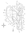
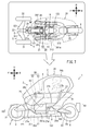
- FIG. 1 is a left side view showing an outline of the overall configuration of the lean vehicle according to the first embodiment.
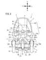
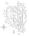
- FIG. 2 is a front view showing an outline of the overall configuration of the lean vehicle according to the first embodiment.
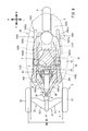
- FIG. 3 is an exploded perspective view showing a schematic structure of the vehicle body frame.
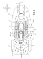
- FIG. 4 is a plan view schematically showing the positional relationship between the vehicle body frame, the vehicle body cover, and the driver.
- FIG. 5 is a schematic view of the tilted link mechanism when the vehicle body frame is tilted to the left when viewed from the rear.
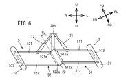
- FIG. 6 is a schematic view of the tilted link mechanism when the vehicle body frame is tilted to the right when viewed from the rear.
- FIG. 1 is a left side view showing an outline of the overall configuration of the lean vehicle according to the first embodiment.
- FIG. 2 is a front view showing an outline of the overall configuration of the lean vehicle according to the first embodiment.
- FIG. 3 is an exploded perspective view showing a schematic structure
- FIG. 7 is a side-by-side view of the left side view of the lean vehicle and the plan view schematically showing the positional relationship between the vehicle body frame, the vehicle body cover, and the driver.
- FIG. 8 is a left side view showing an outline of the overall configuration of the lean vehicle according to the second embodiment.
- FIG. 9 is a plan view showing a schematic configuration of a vehicle body frame of the lean vehicle according to the second embodiment.
- the arrow F in the figure indicates the forward direction of the lean vehicle 1,1001.
- the arrow B in the figure indicates the rear direction of the lean vehicle 1,1001.
- the arrow U in the figure indicates the upward direction of the lean vehicle 1,1001.
- the arrow D in the figure indicates the downward direction of the lean vehicle 1,1001.
- the arrow R in the figure indicates the right direction of the lean vehicle 1,1001.
- the arrow L in the figure indicates the left direction of the lean vehicle 1,1001.
- the front-rear direction, the left-right direction, and the up-down direction of the lean vehicle 1,1001 are the front-rear direction and the left-right direction based on the lean vehicle 1,1001 when viewed from the driver who drives the lean vehicle 1,1001, respectively. And up and down.
- the lean vehicles 1, 1001 of each embodiment turn by inclining the vehicle body frames 21, 1021 in the left-right direction with respect to the vertical direction. Therefore, in FIGS. 5 and 6 showing the state in which the vehicle body frame 21 is tilted, the direction with respect to the vehicle body frame 21 is defined as follows in addition to the direction with respect to the lean vehicle 1 described above.
- the arrow FU in the figure indicates the upward direction of the vehicle body frame 21.
- the arrow FD in the figure indicates the downward direction of the vehicle body frame 21.
- the arrow FR in the figure indicates the right direction of the vehicle body frame 21.
- the arrow FL in the figure indicates the left direction of the vehicle body frame 21.
- the horizontal direction and the vertical direction of the vehicle body frame 21 mean the horizontal direction and the vertical direction with respect to the vehicle body frame 21 when viewed from the occupant who drives the lean vehicle 1, respectively.
- FIG. 1 is a left side view showing an outline of the overall configuration of the lean vehicle 1 according to the first embodiment.
- FIG. 2 is a front view showing an outline of the overall configuration of the lean vehicle 1.
- the lean vehicle 1 includes a vehicle body 2, a pair of left and right front wheels 3, a rear wheel 4, an inclined link mechanism 5, a steering mechanism 6, a shock absorber 7, and a power unit 8 (drive source).
- the lean vehicle 1 of the present embodiment is a vehicle that inclines to the left when turning to the left and to the right when turning to the right. That is, the lean vehicle 1 of the present embodiment tilts the vehicle body 2 and the pair of left and right front wheels 3 to the left when turning to the left, and tilts the vehicle body 2 and the pair of left and right front wheels 3 to the right when turning to the right. It is a vehicle that tilts to the right.
- the vehicle body 2 has a vehicle body frame 21, a rear arm 23, a vehicle body cover 26, and a seat 27.
- the vehicle body frame 21 is in an upright state.
- the vehicle body frame 21 is premised on an upright state.
- the upright state of the vehicle body frame 21 means that the vertical direction of the vehicle body frame 21 is the same as the vertical direction.
- the vehicle body frame 21 supports mounting parts mounted on the lean vehicle 1, such as the vehicle body cover 26, the seat 27, and the power unit 8. Specifically, the vehicle body frame 21 supports the inclined link mechanism 5 at the front portion. The vehicle body frame 21 supports the rear arm support portion 24, the seat 27, and the power unit 8 at the rear portion.
- the power unit 8 has, for example, a motor that is a driving force generation source.
- the power unit 8 may have an engine as the driving force generation source, or may have a hybrid system in which an engine and a motor are combined.
- the driving force output from the power unit 8 is transmitted to the rear wheels 4 by the drive transmission unit 8a.
- the drive transmission unit 8a is supported by a rear arm 23, which will be described later, that rotatably supports the rear wheel 4.
- the drive transmission unit 8a includes, for example, a chain or the like.
- FIG. 3 is an exploded perspective view showing a schematic configuration of a vehicle body frame 21, a pair of left and right front wheels 3, a rear wheel 4, an inclined link mechanism 5, and a steering mechanism 6.
- the vehicle body frame 21 has a main skeleton portion 21a, an inclined link mechanism support portion 22, a rear arm support portion 24, and a handle support portion 25.
- the main skeleton portion 21a is a frame constituting the skeleton of the vehicle body 2 of the lean vehicle 1.
- the detailed configuration of the main skeleton portion 21a will be described later, but the main skeleton portion 21a includes a front skeleton portion 211 and a posterior skeleton portion 212.
- the anterior skeleton portion 211 is located in front of the posterior skeleton portion 212 in the main skeleton portion 21a.
- the posterior skeleton portion 212 is located behind the anterior skeleton portion 211 in the main skeleton portion 21a.
- the anterior skeleton portion 211 and the posterior skeleton portion 212 are connected in a state of being arranged in the front-rear direction.
- the front skeleton portion 211 supports the inclined link mechanism support portion 22 at the front portion.
- the rear skeleton portion 212 supports the power unit 8 and the seat 27 at the front portion, and supports the rear arm support portion 24 at the rear portion.
- the seat 27 is supported by the rear skeleton portion 212 of the vehicle body frame 21.
- the seat 27 has a seating portion 27a and a seat back 27b.
- the seating portion 27a of the seat 27 is supported by the upper portion of the posterior skeleton portion 212.
- the upper surface of the seating portion 27a is a seating surface 27c on which the driver is seated.
- the inclined link mechanism support portion 22 is connected to the front end of the anterior skeleton portion 211.
- the tilted link mechanism support portion 22 supports the tilted link mechanism 5, which will be described later.
- the inclined link mechanism 5 supports a pair of left and right front wheels 3. That is, the inclined link mechanism support portion 22 supports the pair of left and right front wheels 3 via the inclined link mechanism 5.
- the detailed configuration of the inclined link mechanism 5 will be described later.
- the inclined link mechanism support portion 22 is separable from the anterior skeleton portion 211. Therefore, the inclined link mechanism 5 supported by the inclined link mechanism supporting portion 22 is also separable from the main skeleton portion 21a. Further, the inclined link mechanism support portion 22 is also separable from the handle support portion 25, which will be described later, which is connected to the main skeleton portion 21a.
- the pair of left and right front wheels 3 includes a left front wheel 31 located to the left of the vehicle body frame 21 and a right front wheel 32 located to the right of the vehicle body frame 21.
- the left arm mechanism 51 of the inclined link mechanism 5, which will be described later, extends from the inclined link mechanism support portion 22 to the left so as to support the left front wheel 31 with respect to the vehicle body frame 21.
- the right arm mechanism 52 of the inclined link mechanism 5, which will be described later, extends from the inclined link mechanism support portion 22 to the right so as to support the right front wheel 32 with respect to the vehicle body frame 21.
- a shock absorber support portion 28 that supports the shock absorber 7 is arranged between the inclined link mechanism support portion 22 and the anterior skeleton portion 211.
- the shock absorber support portion 28 is connected to the upper portion of the inclined link mechanism support portion 22 and the front lower end portion of the handle support portion 25 connected to the front skeleton portion 211.
- the shock absorber support portion 28 has a shock absorber support main body portion 28a and a tower portion 28b.
- the shock absorber support main body 28a is a cylindrical member and supports the base end portion of the tower portion 28b extending in the vertical direction.
- the shock absorber support main body 28a is connected to the front lower end portion of the inclined link mechanism support portion 22 and the handle support portion 25.
- the buffer device 7 buffers the movements of the left front wheel 31 and the right front wheel 32.
- the shock absorber 7 includes a left shock absorber 71 and a right shock absorber 72.
- the left shock absorber 71 is provided so as to connect the tower portion 28b and the upper left arm member 511 of the inclined link mechanism 5, which will be described later.
- the right shock absorber 72 is provided so as to connect the tower portion 28b and the upper right arm member 521 of the inclined link mechanism 5, which will be described later.
- the left shock absorber 71 and the right shock absorber 72 have a spring and a damper, respectively.
- the left shock absorber 71 buffers the force input from the road surface to the left front wheel 31, and positions the left front wheel 31 with respect to the vehicle body frame 21.
- the right buffer device 72 buffers the force input from the road surface to the right front wheel 32, and positions the right front wheel 32 with respect to the vehicle body frame 21.
- the handle support portion 25 is connected to the upper portion of the front portion of the front skeleton portion 211, and extends upward from the upper portion of the front skeleton portion 211.
- the height H5 of the upper end of the handle support portion 25 is higher than the seating surface 27c of the seat 27.
- the upper end of the handle support portion 25 is a portion located at the top of the handle support portion 25 in the vertical direction.
- a part of the handle support portion 25 may extend upward from the upper part of the main skeleton portion 21a other than the front skeleton portion 211. That is, as long as at least a part of the handle support portion 25 extends upward from the upper part of the front skeleton portion 211, the handle support portion 25 may be provided in the main skeleton portion 21a in any way.
- the handle support portion 25 is formed of a member separate from the main skeleton portion 21a.
- the handle support portion 25 may extend upward from the upper portion of a portion other than the front skeleton portion 211. That is, the handle support portion 25 may extend upward from the upper portion of the main skeleton portion 21a.
- the handle support portion 25 supports the bar handle 61 and the steering shaft 62 of the steering mechanism 6.
- the handle support portion 25 has a height such that the bar handle 61 of the steering mechanism 6 is positioned so that the driver who is seated on the seating surface 27c of the seat 27 can easily grip the bar handle 61.
- the steering mechanism 6 includes a bar handle 61, a steering shaft 62, a steering shaft support portion 63, and a steering force transmission portion (not shown).
- the bar handle 61 is a bar member extending in the left-right direction and is connected to the upper end portion of the steering shaft 62.
- the steering shaft 62 is rotatably supported by the steering shaft support portion 63 fixed to the upper portion of the steering wheel support portion 25 as described later.
- the steering shaft 62 is connected to the steering force transmitting portion so as to transmit the rotation of the bar handle 61.
- the steering force transmission unit transmits the rotation of the steering shaft 62 to the left front wheel 31 and the right front wheel 32 as steering force in the left-right direction. The detailed configuration of the steering force transmission unit will not be described.
- the steering handle SH is configured by the bar handle 61 and the steering shaft 62.
- the steering shaft 62 is a portion supported by the steering shaft support portion 63, and does not include other rotating shafts connected to the steering shaft 62 by a transmission component.
- the steering handle SH rotates about the steering shaft P.
- the handle support portion 25 of the present embodiment has four handle support leg portions 25a, a plurality of handle support beam portions 25b, and a handle support top plate portion 25c.
- the four handle support legs 25a and the plurality of handle support beams 25b are plate-shaped bar members that are long in one direction, respectively.
- the handle support top plate portion 25c is a flat plate member.
- the upper ends of the four handle support legs 25a are connected to the handle support top plate 25c.
- the four handle support legs 25a are connected in the left-right direction by a part of the plurality of handle support beam portions 25b, and are connected in the front-rear direction by the other part of the plurality of handle support beam portions 25b.
- the four handle support legs 25a, the plurality of handle support beams 25b, and the handle support top plate 25c are integrally formed.
- the handle support portion 25 is formed in a turret shape by a plate-shaped bar member.
- the lower ends of the four handle support legs 25a are fixed to the front skeleton portion 211.
- the method of fixing the four handle support legs 25a to the front skeleton portion 211 is a method in which the handle support legs 25a can be fixed to the front skeleton portion 211 such as welding, fastening using a fastening member, and adhesion. If so, any method may be used.
- a steering shaft support portion 63, which will be described later, of the steering mechanism 6 is fixed on the handle support top plate portion 25c.
- the bar handle 61 is connected to a steering shaft 62 rotatably supported by a steering shaft support 63.
- the handle support portion 25 supports the steering handle SH composed of the bar handle 61 and the steering shaft 62.
- the rear arm support portion 24 is connected to the rear end of the rear skeleton portion 212.
- the rear arm support portion 24 rotatably supports the front portions of the pair of left and right rear arms 23.
- the pair of left and right rear arms 23 extend rearward from the rear arm support portion 24, respectively.
- a pair of left and right rear arms 23 rotatably support the rear wheels 4 at their rear portions.
- the body cover 26 (cover) is supported by the body frame 21.
- the vehicle body cover 26 includes a vehicle body cover main body 26a that covers the vehicle body frame 21 and an upper cover 26b that is located above the vehicle body cover main body 26a.
- the upper cover 26b is formed in a convex shape so as to project upward when viewed from the left-right direction. As a result, the upper cover 26b forms a riding space for the driver to ride between the upper cover 26b and the vehicle body cover main body 26a. Therefore, since the driver driving the lean vehicle 1 is not directly exposed to the wind and rain, the comfort of the driver can be improved.
- the upper cover 26b is formed so as to be located above the driver's head while the driver is seated on the seating surface 27c of the seat 27.
- the vehicle body cover main body 26a is formed so as to cover the right portion of the driver seated on the seating surface 27c of the seat 27 while opening the left portion of the driver. As a result, the driver can get on and off the lean vehicle 1 from the left.
- An opening 26c is formed in the lower right part of the vehicle body cover body 26a.
- the opening 26c is provided so that the right foot of the driver seated on the seating surface 27c of the seat 27 can penetrate and land on the ground. That is, the lean vehicle 1 is located to the right of the driver so as to cover the right portion of the driver seated on the seat 27, and when the right foot of the driver seated on the seat 27 lands.
- a vehicle body cover 26 having an opening 26c through which the right foot can penetrate is provided. Thereby, the convenience of the lean vehicle 1 can be improved.
- the above-described configuration eliminates the need for the lean vehicle 1 to have an independent function, so that the configuration of the lean vehicle 1 can be simplified.
- plate-shaped left step 261 and right step 262 are provided in a portion facing the riding space in the front lower portion of the vehicle body cover main body 26a.
- the left step 261 is located on the left side of the vehicle body cover main body 26a, and the left foot of the driver seated on the seating surface 27c of the seat 27 is placed on the left step 261.
- the front part of the left step 261 is inclined forward and upward.
- the right step 262 is located on the right side of the vehicle body cover main body 26a, and the right foot of the driver seated on the seating surface 27c of the seat 27 is placed on the right step 262.
- the front portion of the right step 262 is inclined forward and upward.
- FIG. 4 is a plan view schematically showing the relationship between the driver, the vehicle body frame 21, and the vehicle body cover 26.
- FIG. 7 is a diagram showing FIG. 4 side by side with FIG. In FIGS. 4 and 7, for the sake of explanation, the parts other than the vehicle body frame 21, the left front wheel 31, the right front wheel 32, the rear wheel 4, and the inclined link mechanism 5 are omitted from the lean vehicle 1, and the vehicle body is shown.
- the outer shape of the cover 26 is shown by a alternate long and short dash line.
- Left step 261 is located to the left of the main skeleton portion 21a in a plan view of the lean vehicle 1.
- the right step 262 is located to the right of the main skeleton portion 21a in a plan view of the lean vehicle 1. That is, the main skeleton portion 21a is located between the left step 261 and the right step 262 in the left-right direction.
- the left step 261 and the right step 262 are illustrated by a two-dot chain line and an oblique line for explanation.
- the left step 261 and the right step 262 are integrally formed with the vehicle body cover main body 26a.
- the left step and the right step may be provided separately from the vehicle body cover main body 26a.
- the left step 261 and the right step 262 are supported by the main skeleton portion 21a via the vehicle body cover main body 26a.
- the main skeleton portion 21a may be provided with a step support portion that supports the left step and the right step, respectively.
- the left step and the right step are each supported by the step support portion on the main skeleton portion 21a.
- the left-right distance WS between the left end of the left step 261 and the right end of the right step 262 is smaller than the tread width WH of the left front wheel 31 and the right front wheel 32. That is, the tread width WH of the left front wheel 31 and the right front wheel 32 is larger than the distance WS in the left-right direction between the left end of the left step 261 and the right end of the right step 262.
- the distance in the left-right direction from the ground contact position of the foot before the driver gets on the lean vehicle 1 to the seating surface 27c of the seat 27 is small. As a result, the driver can easily get on and off the lean vehicle 1.
- the tread width between the left front wheel 31 and the right front wheel 32 means the distance between the center of the left front wheel 31 and the center of the right front wheel 32 in the left-right direction of the lean vehicle 1.
- a recessed portion 261a is provided at the left rear portion of the left step 261.
- the recessed portion 261a allows the driver to easily get on and off the lean vehicle 1. Moreover, the driver can land his left foot on the ground while seated on the seating surface 27c of the seat 27. Thereby, the convenience of the lean vehicle 1 can be improved.
- the front portion of the vehicle body cover main body 26a is provided with a front cover 265 that covers the front of a link mechanism drive motor (not shown) that drives the inclined link mechanism 5 described later.
- the front cover 265 constitutes the front portion of the cabin C, which will be described later, so as to cover the front portion of the link mechanism drive motor and the front portion of the driver seated on the seating surface 27c of the seat 27.
- the front cover 265 has a light transmitting portion 265a so that the driver seated on the seating surface 27c of the seat 27 can visually recognize the pair of left and right front wheels 3.
- the light transmitting portion 265a is made of, for example, a transparent material.
- the light transmitting portion 265a may be made of any material as long as it is made of a material capable of transmitting light.
- the front cover 265 is located behind the pair of left and right front wheels 3.
- the left step 261 and the right step 262 are provided at the rear of the front cover 265. Therefore, the front cover 265 can prevent the water splashed by the pair of left and right front wheels 3 from entering the riding space, which is the space in which the driver is riding.
- the upper cover 26b and the front cover 265 of the vehicle body cover body 26a form a cabin C that covers the front and upper parts of the driver seated on the seating surface 27c of the seat 27.
- the cabin C may include a portion of the vehicle body cover body 26a that covers the left portion of the driver, or may include a portion of the vehicle body cover body 26a that covers the right portion of the driver, or the vehicle body cover.
- the portion of the main body 26a that covers the rear part of the driver may be included.
- FIG. 5 is a schematic view of the tilted link mechanism 5 when the vehicle body frame 21 is tilted to the left when viewed from the rear.
- FIG. 6 is a schematic view of the tilted link mechanism 5 when the vehicle body frame 21 is tilted to the right when viewed from the rear.
- the inclined link mechanism 5 is a double wishbone type link mechanism.
- the tilted link mechanism 5 is supported by the tilted link mechanism support portion 22.
- the tilted link mechanism 5 has a left arm mechanism 51 and a right arm mechanism 52.
- the left arm mechanism 51 is connected to the left portion of the inclined link mechanism support portion 22 and the left front wheel 31. As will be described later, the left arm mechanism 51 can rotate in the vertical direction with respect to the inclined link mechanism support portion 22 and the left front wheel 31, respectively. That is, the left arm mechanism 51 rotatably supports the left front wheel 31 with respect to the inclined link mechanism support portion 22 in the vertical direction.
- the left arm mechanism 51 swings upward with respect to the inclined link mechanism support portion 22 when the vehicle body frame 21 is inclined to the left, and lower with respect to the inclined link mechanism support portion 22 when the vehicle body frame 21 is inclined to the right. Swing to.
- the left arm mechanism 51 includes an upper left arm member 511, a lower left arm member 512, and a left knuckle 513.
- the upper left arm member 511 and the lower left arm member 512 are left swing arms.
- the upper left arm member 511 is a flat plate member, and is arranged between the inclined link mechanism support portion 22 and the left front wheel 31 so as to extend in the left-right direction.
- the right end portion of the upper left arm member 511 is rotatably connected to the inclined link mechanism support portion 22 in the vertical direction around the right end portion of the upper left arm member 511.
- the portion where the right end portion of the upper left arm member 511 is rotatably connected to the inclined link mechanism support portion 22 is the support portion 511a of the upper left arm member 511 with respect to the inclined link mechanism support portion 22.
- the left end portion of the upper left arm member 511 is rotatably connected to the left knuckle 513 connected to the wheel of the left front wheel 31 in the vertical direction around the left end portion of the upper left arm member 511.
- the lower left arm member 512 is a flat plate member, and is arranged under the upper left arm member 511 in parallel with the upper left arm member 511. That is, the lower left arm member 512 is also arranged between the inclined link mechanism support portion 22 and the left front wheel 31 so as to extend in the left-right direction, similarly to the upper left arm member 511.
- the right end portion of the lower left arm member 512 is rotatably connected to the inclined link mechanism support portion 22 in the vertical direction around the right end portion of the lower left arm member 512.
- the portion where the right end portion of the lower left arm member 512 is rotatably connected to the inclined link mechanism support portion 22 is the support portion 512a of the lower left arm member 512 with respect to the inclined link mechanism support portion 22.
- the left end portion of the lower left arm member 512 is rotatably connected to the left knuckle 513 connected to the wheel of the left front wheel 31 in the vertical direction around the left end portion of the lower left arm member 512.
- the left arm mechanism 51 With the configuration of the left arm mechanism 51 as described above, when the vehicle body frame 21 is tilted to the left, the left knuckle 513 is tilted to the left in parallel with the tilting link mechanism support portion 22. At this time, the upper left arm member 511 and the lower left arm member 512 are maintained in a parallel state. On the other hand, when the vehicle body frame 21 is tilted to the right, the left knuckle 513 is tilted to the right in parallel with the tilting link mechanism support portion 22. At this time, the upper left arm member 511 and the lower left arm member 512 are maintained in a parallel state.
- the right arm mechanism 52 is connected to the right portion of the inclined link mechanism support portion 22 and the right front wheel 32. As will be described later, the right arm mechanism 52 can rotate in the vertical direction with respect to the inclined link mechanism support portion 22 and the right front wheel 32, respectively. That is, the right arm mechanism 52 rotatably supports the right front wheel 32 in the vertical direction with respect to the inclined link mechanism support portion 22.
- the right arm mechanism 52 swings downward with respect to the inclined link mechanism support portion 22 when the vehicle body frame 21 is inclined to the left, and is upward with respect to the inclined link mechanism support portion 22 when the vehicle body frame 21 is inclined to the right. Swing to.
- the right arm mechanism 52 has an upper right arm member 521, a lower right arm member 522, and a right knuckle 523.
- the upper right arm member 521 and the lower right arm member 522 are right swing arms.
- the upper right arm member 521 is a flat plate member, and is arranged between the inclined link mechanism support portion 22 and the right front wheel 32 so as to extend in the left-right direction.
- the left end portion of the upper right arm member 521 is rotatably connected to the inclined link mechanism support portion 22 in the vertical direction around the left end portion of the upper right arm member 521.
- the portion where the left end portion of the upper right arm member 521 is rotatably connected to the inclined link mechanism support portion 22 is the support portion 521a of the upper right arm member 521 with respect to the inclined link mechanism support portion 22.
- the right end portion of the upper right arm member 521 is rotatably connected to the right knuckle 523 connected to the wheel of the right front wheel 32 in the vertical direction around the right end portion of the upper right arm member 521.
- the lower right arm member 522 is a flat plate member, and is arranged under the upper right arm member 521 in parallel with the upper right arm member 521. That is, the lower right arm member 522 is also arranged between the inclined link mechanism support portion 22 and the right front wheel 32 so as to extend in the left-right direction, similarly to the upper right arm member 521.
- the left end portion of the lower right arm member 522 is rotatably connected to the inclined link mechanism support portion 22 in the vertical direction around the left end portion of the lower right arm member 522.
- the portion where the left end portion of the lower right arm member 522 is rotatably connected to the inclined link mechanism support portion 22 is the support portion 522a of the lower right arm member 522 with respect to the inclined link mechanism support portion 22.
- the right end portion of the lower right arm member 522 is rotatably connected to the right knuckle 523 connected to the wheel of the right front wheel 32 in the vertical direction around the right end portion of the lower right arm member 522.
- the right arm mechanism 52 With the configuration of the right arm mechanism 52 as described above, when the vehicle body frame 21 is tilted to the left, the right knuckle 523 is tilted to the left in parallel with the tilting link mechanism support portion 22. At this time, the upper right arm member 521 and the lower right arm member 522 maintain a parallel state. On the other hand, when the vehicle body frame 21 is tilted to the right, the right knuckle 523 is tilted to the right in parallel with the tilting link mechanism support portion 22. At this time, the upper right arm member 521 and the lower right arm member 522 maintain a parallel state.
- the vehicle body frame 21, the left front wheel 31, and the right front wheel 32 can be inclined to the left or right by the inclined link mechanism 5 having the above-described configuration.
- the above-mentioned tilt link mechanism 5 may be configured so that the tilt in the left-right direction is controlled by the link mechanism drive motor.
- the link mechanism drive motor is arranged, for example, behind the inclined link mechanism support portion 22 and behind the front cover 265.
- the main skeleton portion 21a extends in the front-rear direction. That is, the width of the main skeleton portion 21a in the left-right direction is smaller than the length of the main skeleton portion 21a in the front-rear direction.
- the main skeleton portion 21a includes an anterior skeleton portion 211 and a posterior skeleton portion 212.
- the anterior skeleton portion 211 is located in front of the posterior skeleton portion 212.
- the anterior skeleton portion 211 extends in the anteroposterior direction.
- the anterior skeleton portion 211 has a pair of anterior skeleton side wall portions 211a and an anterior skeleton bottom wall portion 211b.
- the pair of anterior skeleton side wall portions 211a are located side by side in the left-right direction and are long in the front-rear direction.
- the front skeleton bottom wall portion 211b connects the lower ends of the pair of front skeleton side wall portions 211a.
- the pair of anterior skeleton side wall portions 211a and the anterior skeleton bottom wall portion 211b are connected by welding, for example.
- the pair of front skeleton side wall portions 211a and front skeleton bottom wall portion 211b may be connected by adhesion, bolts, or the like, or may be integrally formed.
- the height dimension of the pair of front skeleton side wall portions 211a is lower in the rear portion than in the front portion, respectively.
- the front skeleton portion 211 can be arranged at the feet of the driver seated on the seating surface 27c of the seat 27. Therefore, since the main skeleton portion 21a can be arranged in the lower part of the lean vehicle 1, the center of gravity of the lean vehicle 1 can be lowered.
- the portion of the main skeleton portion 21a located before the center X in the front-rear direction of the left step 261 and the right step 262 is the main skeleton front portion 121.
- the main skeleton anterior portion 121 includes a part of the anterior skeleton portion 211.
- the front portion 121 of the main skeleton extends linearly in the front-rear direction.
- the distance D between the support portion 511a of the upper left arm 511 with respect to the tilted link mechanism support portion 22 and the support portion 521a of the upper right arm 521 with respect to the tilted link mechanism support portion 22 in the dimension WF in the vehicle width direction of the main skeleton front portion 121 (FIG. It is configured to be larger than 5 and FIG. 6).
- the distance D (the distance D between the support portion 512a of the lower left arm 512 with respect to the tilted link mechanism support portion 22 and the support portion 522a of the lower right arm 522 with respect to the tilted link mechanism support portion 22 of the main skeleton front portion 121 in the vehicle width direction is It is configured to be larger than (see FIGS. 5 and 6).
- the upper end of the main skeleton front portion 121 is lower than the lower end of the steering handle SH. That is, the height H2 at the upper end of the front portion 121 of the main skeleton is smaller than the height H1 at the lower end of the steering handle SH.
- the lower end of the steering handle SH is the lowermost portion of the bar handle 61 and the steering shaft 62. In the case of this embodiment, the lower end of the steering handle SH is the lower end of the steering shaft 62.
- the upper end of the main skeleton front portion 121 is the uppermost portion of the main skeleton front portion 121.
- the upper end of the main skeleton front portion 121 is the front portion of the front skeleton portion 211.
- the upper end of the front part 121 of the main skeleton is lower than the seating surface 27c of the seat 27. That is, the height H2 of the upper end of the main skeleton front portion 121 is smaller than the height H3 of the seating surface 27c of the seat 27.
- the height H3 of the seating surface 27c of the above-mentioned seat is the height of the lowest portion of the seating surface 27c.
- the upper end of the main skeleton front portion 121 is lower than the upper end of the inclined link mechanism 5. That is, as shown in FIG. 2, the height H2 of the upper end of the main skeleton front portion 121 is smaller than the height H4 of the inclined link mechanism 5. As a result, it is possible to increase the degree of freedom in the riding position of the driver and the layout of the mounted parts mounted on the vehicle body frame. Therefore, the degree of freedom in designing the lean vehicle can be increased.
- the upper end of the inclined link mechanism 5 is the uppermost portion of the inclined link mechanism 5.
- the height in this embodiment means the height from the road surface on which the lean vehicle 1 travels.
- a plate-shaped reinforcing member 213 is provided on the upper portion of the central portion in the front-rear direction of the pair of front skeleton side wall portions 211a.
- the reinforcing member 213 is connected to the central portion in the front-rear direction of the pair of front skeleton side wall portions 211a so as to straddle the left-right direction. It is not necessary to provide the reinforcing member 213.
- the reinforcing member 213 may have another shape such as a rod shape.
- the posterior skeleton portion 212 is located behind the anterior skeleton portion 211.
- the posterior skeleton portion 212 extends in the anteroposterior direction.
- the posterior skeleton portion 212 has a pair of posterior skeleton side wall portions 212a and a plurality of posterior skeleton beam portions 212b.
- the pair of posterior skeleton side wall portions 212a are located side by side in the left-right direction and are long in the front-rear direction.
- the plurality of posterior skeleton beam portions 212b connect a pair of posterior skeleton side wall portions 212a in the left-right direction.
- the vertical dimension of the rear skeleton portion 212 is larger than the vertical dimension of the front skeleton portion 211.
- the left-right dimension of the posterior skeleton portion 212 is smaller than the left-right dimension of the front skeleton portion 211.
- the rear skeleton portion 212 supports the power unit 8.
- the posterior skeleton portion 212 supports the seat 27 at the top.
- the rear skeleton portion 212 supports the rear arm support portion 24 at the rear end portion.
- An opening 212c is formed in the rear skeleton side wall portion 212a of the posterior skeleton portion 212.
- the posterior skeleton side wall portion 212a may not be provided with an opening.
- the anterior skeleton portion 211 and the posterior skeleton portion 212 are connected side by side in the front-rear direction.
- the vehicle body frame 21 has a long shape in the front-rear direction as described above.
- the portion located behind the center X in the front-rear direction of the left step 261 and the right step 262 is the rear portion 122 of the main skeleton.
- the rear main skeleton 122 includes a posterior anterior skeleton 211 and a posterior skeleton 212.
- the main skeleton portion 21a is located between the left step 261 and the right step 262 provided on the vehicle body cover main body 26a in a plan view.
- the main skeleton portion 21a extends linearly in the front-rear direction between the driver's legs when the driver puts his / her feet on the left step 261 and the right step 262 while the driver is seated on the seat 27.
- the main skeleton portion 21a supports the inclined link mechanism 5 by the main skeleton front portion 121 located in front of the front-rear direction center X of the left step 261 and the right step 262, and the left-right step 261 and the right step 262 are centered in the left-right direction.
- the seat 27, the rear wheels 4, and the power unit 8 are supported by the rear portion 122 of the main skeleton located behind the X.
- the main skeleton front portion 121 views at least a part of the inclined link mechanism 5 at a position below the upper surface of at least a part of the left step 261 and the right step 262 in the side view of the lean vehicle 1.
- the main skeleton portion 21a has a shape that is narrow and extends linearly.
- the main skeleton portion 21a supports an inclined link mechanism 5 that supports the vehicle body frame 21, the left front wheel 31 and the right front wheel 32 so as to be inclined in the left-right direction by the main skeleton front portion 121, and the other by the main skeleton rear portion 122. Support the mounted parts.
- the main skeleton portion 21a of the present embodiment has left step 261 and right step 262 in which the driver puts his / her foot on the seating surface 27c of the seat 27 in the side view of the lean vehicle 1. It extends linearly in the anteroposterior direction, at least below some of the upper surfaces. As a result, it is possible to increase the degree of freedom in the riding position of the driver and the layout of the mounted parts mounted on the vehicle body frame 21. Therefore, the degree of freedom in designing the lean vehicle 1 can be increased.
- the driver can use the lean vehicle 1 even in the case of the lean vehicle 1 of the present embodiment having the upper cover 26b. Easy to get on and off.
- the main skeleton front portion 121 is provided with a support portion 511a of the upper left arm member 511 with respect to the vehicle body frame 21 and a support portion 521a of the upper right arm member 521 with respect to the vehicle body frame 21 having a dimension WF in the vehicle width direction.
- the space By configuring the space to be larger than the interval D, the rigidity of the main skeleton front portion 121 can be increased as compared with the portion of the vehicle body frame 21 that supports the upper left arm member 511 and the upper right arm member 521.
- the dimension WF of the main skeleton front portion 121 in the vehicle width direction is larger than the distance D between the support portion 512a of the lower left arm member 512 with respect to the vehicle body frame 21 and the support portion 522a of the lower right arm member 522 with respect to the vehicle body frame 21.
- the rigidity of the front part 121 of the main skeleton can be increased as compared with the portion of the vehicle body frame 21 that supports the lower left arm member 512 and the lower right arm member 522. Therefore, it is possible to suppress the deformation of the main skeleton front portion 121 by the force input from the left front wheel 31 via the lower left arm member 512 and the force input from the right front wheel 32 via the lower right arm member 522. .. Therefore, with the above configuration, the rigidity of the entire body frame 21 can be increased.
- FIG. 8 is a left side view showing a schematic configuration of the lean vehicle 1001 according to the second embodiment.
- FIG. 9 is a plan view showing a schematic configuration of the vehicle body frame 1021 of the lean vehicle 1001.
- the floor 1029 described later including the left step 261 and the right step 262 is shown by a two-dot chain line and an oblique line.
- the configuration of the vehicle body frame 1021 is different from the configuration of the vehicle body frame 21 of the lean vehicle 1 of the first embodiment.
- the same components as those in the first embodiment are designated by the same reference numerals and the description thereof will be omitted, and only the parts different from the first embodiment will be described.
- the vehicle body frame 1021 has a main skeleton portion 1021a, an inclined link mechanism support portion 22, and a handle support portion 25.
- the main skeleton portion 1021a has a pipe-shaped left main frame 1041 and a right main frame 1042 extending in the front-rear direction under the left step 261 and the right step 262.
- the left main frame 1041 is located on the left side of the lean vehicle 1001 in a plan view.
- the right main frame 1042 is located on the right side of the lean vehicle 1001 in a plan view.
- the left main frame 1041 and the right main frame 1042 of the present embodiment are provided symmetrically with respect to the center in the left-right direction of the lean vehicle 1001 in a plan view.
- the left step 261 and the right step 262 are composed of a plate-shaped floor 1029 located on the left main frame 1041 and the right main frame 1042.
- the front part of floor 1029 is inclined forward and upward.
- the rear part of the floor 1029 is flat. That is, in the present embodiment, the left step 261 and the right step 262 are integrally formed.
- the upper surfaces of the left step 261 and the right step 262 are the upper surfaces of the floor 1029.
- the left main frame 1041 has a left main frame front portion 1041a, a left main frame rear portion 1041c, and a left main frame intermediate portion 1041b.
- the left main frame front portion 1041a, the left main frame intermediate portion 1041b, and the left main frame rear portion 1041c are connected side by side in the front-rear direction.
- the left main frame intermediate portion 1041b extends in the front-rear direction under the left step 261.
- the left main frame intermediate portion 1041b supports the seat 27.
- the left main frame front portion 1041a extends diagonally forward and upward from the front portion of the left main frame intermediate portion 1041b.
- the left main frame front portion 1041a is formed so that the front end portion approaches the front end portion of the right main frame front portion 1042a, which will be described later, that is, the front end portion approaches the center of the lean vehicle 1 in the left-right direction in a plan view. There is.
- the front end portion of the left main frame front portion 1041a is connected to the inclined link mechanism support portion 22 via the shock absorber support portion 28.
- the left main frame front portion 1041a supports the handle support portion 25 together with the right main frame front portion 1042a described later.
- the left main frame rear portion 1041c has a shape that extends upward from the rear end of the left main frame intermediate portion 1041b and is bent so as to go backward.
- the left main frame rear portion 1041c is integrally formed with the left main frame intermediate portion 1041b.
- the right main frame 1042 has a right main frame front portion 1042a, a right main frame rear portion 1042c, and a right main frame intermediate portion 1042b.
- the front right main frame 1042a, the middle right main frame 1042b, and the rear right main frame 1042c are connected side by side in the front-rear direction.
- the right main frame intermediate portion 1042b extends in the front-rear direction under the right step 262.
- the right main frame intermediate portion 1042b supports the seat 27.
- the right main frame front portion 1042a extends diagonally forward and upward from the front portion of the right main frame intermediate portion 1042b.
- the right main frame front portion 1042a is formed so that the front end portion approaches the front end portion of the right main frame front portion 1042a described later, that is, the front end portion approaches the center in the left-right direction of the lean vehicle 1 in a plan view. There is.
- the front end portion of the right main frame front portion 1042a is connected to the inclined link mechanism support portion 22 via the shock absorber support portion 28.
- the right main frame front portion 1042a supports the handle support portion 25 together with the left main frame front portion 1041a.
- the right main frame rear portion 1042c has a shape that extends upward from the right main frame intermediate portion 1042b and is bent so as to go backward.
- the right main frame rear portion 1042c is integrally formed with the right main frame intermediate portion 1042b.
- the left main frame intermediate portion 1041b and the right main frame intermediate portion 1042b are connected by a front connecting portion 1043 extending in the left-right direction.
- the left main frame rear portion 1041c and the right main frame rear portion 1042c are connected by a rear connecting portion 1044 extending in the left-right direction behind the front connecting portion 1043.
- the rear connecting portion 1044 rotatably supports the front portion of the swing arm 1023 in the vertical direction.
- the swing arm 1023 rotatably supports the rear wheel 4 instead of the rear arm of the first embodiment.
- the swing arm 1023 is provided with a power unit 8.
- a battery 81 that supplies electric power to the power unit 8 is arranged between the left mainframe intermediate portion 1041b and the right mainframe intermediate portion 1042b.
- the drive source of the lean vehicle 1001 includes an engine
- a fuel tank is arranged between the left main frame intermediate portion 1041b and the right main frame intermediate portion 1042b.
- the main skeleton portion 1021a extends linearly in the front-rear direction at a position below the upper surfaces of the left step 261 and the right step 262. As a result, the center of gravity of the lean vehicle 1001 can be lowered, and the driver can easily get on and off the lean vehicle 1001.
- the main skeleton portion 1021a is positioned below the upper surface of the left step 261 and the right step 262 on which the driver rests his / her foot while sitting on the seating surface 27c of the seat 27 in the side view of the lean vehicle 1001. Therefore, by configuring the vehicle so as to extend linearly in the front-rear direction, it is possible to increase the degree of freedom in the riding position of the driver and the layout of the mounted parts mounted on the vehicle body frame 1021. Therefore, the degree of freedom in designing the lean vehicle 1001 can be increased.
- the portion located in front of the center X in the front-rear direction of the left step 261 and the right step 262 is the main skeleton front portion 1121.
- the main skeleton front portion 1121 includes a left main frame front portion 1041a, a right main frame front portion 1042a, a front portion of the left main frame intermediate portion 1041b, and a front portion of the right main frame intermediate portion 1042b.
- the portion located behind the center X in the front-rear direction of the left step 261 and the right step 262 is the main skeleton rear portion 1122.
- the main skeleton rear 1122 includes the rear of the left main frame middle 1041b, the rear of the right main frame middle 1042b, the left main frame rear 1041c and the right main frame rear 1042c.
- the main skeleton portion 1021a supports the inclined link mechanism 5 by the main skeleton front portion 1121 and the seat 27, the rear wheel 4 and the power unit 8 by the main skeleton rear portion 1122.
- the main skeleton portion 1021a of the vehicle body frame 1021 supports the inclined link mechanism 5 that supports the vehicle body frame 1021, the left front wheel 31 and the right front wheel 32 so as to be inclined in the left-right direction by the main skeleton front portion 1121.
- the rear part 1122 of the main skeleton supports other mounting components.
- the upper end of the main skeleton front portion 1121 is lower than the lower end of the steering handle SH. That is, the height H2 of the upper end of the front part 1121 of the main skeleton is smaller than the height H1 of the lower end of the steering handle SH.
- the degree of freedom in designing the lean vehicle 1001 can be increased.
- the lower end of the steering handle SH is the lowermost portion of the bar handle 61 and the steering shaft 62. In the case of this embodiment, the lower end of the steering handle SH is the lower end of the steering shaft 62.
- the upper end of the main skeleton front part 1121 is the uppermost part in the main skeleton front part 1121.
- the upper end of the main skeleton front portion 1121 is the front end of the left main frame front portion 1041a and the right main frame 1042a.
- the upper end of the front part 1121 of the main skeleton is lower than the seating surface 27c of the seat 27. That is, the height H2 of the upper end of the front part 1121 of the main skeleton is smaller than the height H3 of the seating surface 27c of the seat 27.
- the height H3 of the seating surface 27c of the above-mentioned seat is the height of the lowest portion of the seating surface 27c.
- the height in the present embodiment means the height from the road surface on which the lean vehicle 1001 travels.
- the left-right distance WS between the left end of the left step 261 and the right end of the right step 262 is smaller than the tread width WH of the left front wheel 31 and the right front wheel 32. That is, the tread width WH of the left front wheel 31 and the right front wheel 32 is larger than the distance WS in the left-right direction between the left end of the left step 261 and the right end of the right step 262.
- the distance in the left-right direction from the ground contact position of the foot before the driver gets on the lean vehicle 1001 to the seating surface 27c of the seat 27 is small. As a result, the driver can easily get on and off the lean vehicle 1001.
- the tread width between the left front wheel 31 and the right front wheel 32 means the distance between the center of the left front wheel 31 and the center of the right front wheel 32 in the left-right direction of the lean vehicle 1001.
- the main skeleton front portion 1121 is an inclined link at a position below the upper surface of at least a part of the left step 261 and the right step 262 in the side view of the lean vehicle 1001. Supports at least part of the mechanism 5.
- the main skeleton front portion 1121 has a dimension WF in the vehicle width direction of the support portion 511a of the upper left arm member 511 with respect to the vehicle body frame 1021 and the upper right arm member with respect to the vehicle body frame 1021.
- the distance D from the support portion 521a of the 521 is larger than the distance D.
- the dimension WF in the vehicle width direction of the main skeleton front portion 1121 is larger than the distance D between the support portion 512a of the lower left arm member 512 with respect to the vehicle body frame 1021 and the support portion 522a of the lower right arm member 522 with respect to the vehicle body frame 1021. It is configured to be.
- the dimension WF in the vehicle width direction of the main skeleton front portion 1121 is the vehicle width direction dimension of the front end portion of the main skeleton front portion 1121.
- the handle support portion 25 is provided separately from the front skeleton portion 211.
- the handle support portion may be provided integrally with the anterior skeleton portion. That is, the handle support portion may be provided integrally with the main skeleton portion.
- the main skeleton portion 21a includes a front skeleton portion 211 and a posterior skeleton portion 212.
- the main skeleton portion may include at least a part of the casing of the power unit in addition to the anterior skeleton portion and the posterior skeleton portion.
- the inclined link mechanism 5 is a double wishbone type link mechanism having an upper left arm 511 and an upper right arm 521, and a lower left arm 512 and a lower right arm 522.
- the tilted link mechanism may have only one arm, the upper arm and the lower arm.
- the main skeleton portion 21a includes a front skeleton portion 211 and a posterior skeleton portion 212.
- the main skeleton portion may be integrally formed, or may be formed by connecting three or more members in the front-rear direction.
- the main skeleton portion may be configured by connecting a plurality of parts in the left-right direction.
- the main skeleton portion may be configured by using a pipe member.
- the rear portion of the anterior skeleton portion 211 is lower than the anterior portion.
- the anterior skeleton may have the same height in the anterior-posterior direction, or the anterior portion may be lower than the posterior portion.
- the left-right dimension of the posterior skeleton portion 212 is smaller than the left-right dimension of the anterior skeleton portion 211, and the height of the posterior skeleton portion 212 is larger than the height of the anterior skeleton portion 211.
- the left-right dimension of the posterior skeleton portion may be the same as or larger than the left-right dimension of the anterior skeleton portion.
- the height of the posterior skeleton may be the same as the anterior skeleton or smaller than the anterior skeleton.
- the support portion 511a of the upper left arm 511 and the support portion 521a of the upper right arm 521 are located at separate positions.
- the support portion 512a of the lower left arm 512 and the support portion 522a of the lower right arm 522 are located at separate positions.
- the support portion of the upper left arm and the support portion of the upper right arm may be at the same position.
- the support portion of the lower left arm and the support portion of the lower right arm may be at the same position.
- the upper ends of the main skeleton front portions 121 and 1121 are lower than the lower ends of the steering handle SH.
- the upper end of the front portion of the main skeleton may be at the same height as or higher than the lower end of the steering handle.
- the upper ends of the main skeleton front portions 121 and 1121 are lower than the seating surface 27c of the seat 27.
- the upper end of the front portion of the main skeleton may be at the same height as the seating surface of the seat or higher than the seating surface.
- the upper end of the main skeleton front portion 121 is lower than the upper end of the inclined link mechanism 5.
- the upper end of the anterior portion of the main skeleton may be at or above the upper end of the tilted linkage.
- the tread width WH of the left front wheel 31 and the right front wheel 32 is larger than the distance WS in the left-right direction between the left end of the left step 261 and the right end of the right step 262.
- the tread width between the left front wheel and the right front wheel may be the same as or smaller than the horizontal distance between the left end of the left step and the right end of the right step.
- the handle support portion 25 is formed in a turret shape by a plate-shaped bar member.
- the steering wheel support portion may be formed of a pipe member or a plate-shaped member as long as the steering handle can be rotatably supported.
- the power unit 8 is provided on the swing arm 1023.
- the power unit may be provided on the rear wheels.
- a wheel-in motor may be provided on the rear wheels.
- the main skeleton portion 2021a of the vehicle body frame 1021 of the lean vehicle 1001 has a pipe-shaped left main frame 1041 and a right main frame 1042 extending in the front-rear direction under the left step 261 and the right step 262.
- the left main frame and the right main frame may be composed of members obtained by bending a flat plate into a U shape.
- the main skeleton portion may have a frame other than the left main frame and the right main frame.
- the configuration of the main skeleton portion is not limited to the configuration of the second embodiment.
- the seat 27 has a seating portion 27a and a seat back 27b.
- the seat may be a so-called saddle-type seat having only a seating portion.
- the three-wheeled vehicle has been described as an example of the lean vehicle, but the lean vehicle may be a vehicle other than the three-wheeled vehicle such as a four-wheeled vehicle.
Abstract
Provided is a leaning vehicle that can increase the degree of freedom in designing a leaning vehicle, including the degree of freedom in a riding position of a driver, and a layout of components mounted on a vehicle body frame. The leaning vehicle 1 comprises a vehicle body frame 21, a seat 27, a left step 261 and a right step 262, a left front wheel 31, a right front wheel 32, a rear wheel 4, and an inclination link mechanism 5. A main framework front portion 121 of a main framework part 21a of the vehicle body frame 21 extends linearly in the front-rear direction, and is configured to have a vehicle width direction dimension larger than an interval between a support portion of an upper left arm member 511 with respect to the vehicle body frame 21 and a support portion of an upper right arm member 521 with respect to the vehicle body frame 21. In addition, in a side view of the leaning vehicle 1, the main framework front portion 121 supports at least a portion of the inclination link mechanism 5 at a position below the upper surface of at least a portion of the left step 261 and the right step 262.
Description
本発明は、リーン車両に関する。
The present invention relates to a lean vehicle.
左に旋回する際に左に傾斜し、右に旋回する際に右に傾斜するリーン車両が知られている。このようなリーン車両として、例えば特許文献1には、車体フレームと、2つの前輪と、1つの後輪とを有する三輪傾斜車両が開示されている。2つの前輪は、左前輪及び右前輪を含む。
A lean vehicle is known that tilts to the left when turning to the left and tilts to the right when turning to the right. As such a lean vehicle, for example, Patent Document 1 discloses a three-wheel tilting vehicle having a body frame, two front wheels, and one rear wheel. The two front wheels include a left front wheel and a right front wheel.
リーン車両において、運転者の乗車位置、車体フレームに搭載される搭載部品のレイアウトなどの自由度を含むリーン車両の設計自由度を高めることが望まれている。
In lean vehicles, it is desired to increase the degree of freedom in designing lean vehicles, including the degree of freedom in the driver's riding position and the layout of mounted parts mounted on the vehicle body frame.
本発明は、運転者の乗車位置、車体フレームに搭載される搭載部品のレイアウトなどの自由度を含むリーン車両の設計自由度を高めることができるリーン車両を提供することを目的とする。
An object of the present invention is to provide a lean vehicle capable of increasing the degree of freedom in designing a lean vehicle, including the degree of freedom in the riding position of the driver and the layout of mounted parts mounted on the vehicle body frame.
本発明の一実施形態に係るリーン車両は、車体フレームと、前記車体フレームに支持され、運転者が着座するシートと、前記車体フレームに支持され、運転者が足を載せる左ステップ及び右ステップと、前記車体フレームの左に位置する左前輪と、前記車体フレームの右に位置する右前輪と、少なくとも一つの後輪と、前記左前輪を前記車体フレームに対して揺動可能に支持する左揺動アームと、前記右前輪を前記車体フレームに対して揺動可能に支持する右揺動アームと、を有し、前記車体フレーム、前記左前輪及び前記右前輪を左右方向に傾斜するように支持する傾斜リンク機構と、前記左前輪及び前記右前輪の動きを緩衝する緩衝装置とを備え、左に旋回する際には前記車体フレーム、前記左前輪、前記右前輪及び前記後輪を左に傾斜し且つ右に旋回する際には前記車体フレーム、前記左前輪、前記右前輪及び前記後輪を右に傾斜するリーン車両である。前記車体フレームは、メイン骨格部を備える。前記メイン骨格部において前記左ステップ及び前記右ステップの前後方向中央よりも前に位置するメイン骨格前部は、前後方向に直線的に延びるとともに、前記メイン骨格前部の車両幅方向の寸法が前記車体フレームに対する前記左揺動アームの支持部と前記車体フレームに対する前記右揺動アームの支持部との間隔よりも大きくなるように構成され、且つ、リーン車両の側面視で、前記左ステップ及び前記右ステップの少なくとも一部の上面よりも下の位置で前記傾斜リンク機構の少なくとも一部を支持する。
The lean vehicle according to an embodiment of the present invention includes a vehicle body frame, a seat supported by the vehicle body frame and seated by the driver, and a left step and a right step supported by the vehicle body frame on which the driver puts his / her feet. , Left front wheel located to the left of the vehicle body frame, right front wheel located to the right of the vehicle body frame, at least one rear wheel, and left swing that oscillatingly supports the left front wheel with respect to the vehicle body frame. It has a moving arm and a right swing arm that swingably supports the right front wheel with respect to the vehicle body frame, and supports the vehicle body frame, the left front wheel, and the right front wheel so as to be inclined in the left-right direction. It is provided with an inclined link mechanism for tilting the left front wheel and a shock absorbing device for buffering the movement of the right front wheel, and when turning to the left, the vehicle body frame, the left front wheel, the right front wheel and the rear wheel are inclined to the left. It is a lean vehicle that tilts the vehicle body frame, the left front wheel, the right front wheel, and the rear wheel to the right when turning to the right. The vehicle body frame includes a main skeleton portion. The front part of the main skeleton located in front of the center of the left step and the right step in the front-rear direction in the main skeleton extends linearly in the front-rear direction, and the dimension of the front part of the main skeleton in the vehicle width direction is said. It is configured to be larger than the distance between the support portion of the left swing arm with respect to the vehicle body frame and the support portion of the right swing arm with respect to the vehicle body frame, and the left step and the said in a side view of the lean vehicle. At least a part of the tilted link mechanism is supported at a position below the upper surface of at least a part of the right step.
このように、メイン骨格前部を、前後方向に直線的に延びるとともに、前記メイン骨格前部の車両幅方向の寸法が車体フレームに対する左揺動アームの支持部と前記車体フレームに対する右揺動アームの支持部との間隔よりも大きくなるように構成し、且つ、リーン車両の側面視で、前記左ステップ及び前記右ステップの少なくとも一部の上面よりも下の位置で傾斜リンク機構の少なくとも一部を支持するように構成することにより、運転者の乗車位置、車体フレームに搭載される搭載部品のレイアウトなどの自由度を高めることができる。よって、リーン車両の設計自由度を高めることができる。
In this way, the front part of the main skeleton extends linearly in the front-rear direction, and the dimensions of the front part of the main skeleton in the vehicle width direction are the support portion of the left swing arm with respect to the vehicle body frame and the right swing arm with respect to the vehicle body frame. At least a part of the tilted link mechanism at a position below the upper surface of at least a part of the left step and the right step in the side view of the lean vehicle, which is configured to be larger than the distance from the support portion of the vehicle. By configuring the vehicle so as to support the above, it is possible to increase the degree of freedom in the riding position of the driver and the layout of the mounted parts mounted on the vehicle body frame. Therefore, the degree of freedom in designing the lean vehicle can be increased.
他の観点によれば、本発明のリーン車両は、以下の構成を含むことが好ましい。前記メイン骨格部は、平面視で前記左ステップと前記右ステップとの間に位置する。
From another point of view, the lean vehicle of the present invention preferably includes the following configurations. The main skeleton portion is located between the left step and the right step in a plan view.
このように、メイン骨格部が、平面視で、左ステップと右ステップとの間に位置することにより、運転者の乗車位置、車体フレームに搭載される搭載部品のレイアウトなどの自由度を高めることができる。よって、リーン車両の設計自由度を高めることができる。
In this way, by locating the main skeleton between the left step and the right step in a plan view, the degree of freedom in the driver's riding position and the layout of the mounted parts mounted on the vehicle body frame is increased. Can be done. Therefore, the degree of freedom in designing the lean vehicle can be increased.
他の観点によれば、本発明のリーン車両は、以下の構成を含むことが好ましい。前記メイン骨格部は、運転者が前記シートに着座した状態で前記左ステップ及び前記右ステップに足を載せた時の前記運転者の両脚の間を前後方向に直線的に延びる。
From another point of view, the lean vehicle of the present invention preferably includes the following configurations. The main skeleton portion extends linearly in the front-rear direction between both legs of the driver when the driver puts his / her feet on the left step and the right step while the driver is seated on the seat.
このように、メイン骨格部は、幅が狭く前後方向に直線的に延びる形状である。これにより、運転者の乗車位置、車体フレームに搭載される搭載部品のレイアウトなどの自由度を高めることができる。よって、リーン車両の設計自由度を高めることができる。
In this way, the main skeleton has a narrow width and a shape that extends linearly in the front-rear direction. As a result, it is possible to increase the degree of freedom in the riding position of the driver and the layout of the mounted parts mounted on the vehicle body frame. Therefore, the degree of freedom in designing the lean vehicle can be increased.
他の観点によれば、本発明のリーン車両は、以下の構成を含むことが好ましい。前記メイン骨格部は、リーン車両の側面視で、前記運転者が前記シートに着座した状態で足を載せる前記左ステップ及び前記右ステップの上面よりも下の位置で、前後方向に直線的に延びる。
From another point of view, the lean vehicle of the present invention preferably includes the following configurations. The main skeleton portion extends linearly in the front-rear direction at a position below the upper surface of the left step and the right step on which the driver puts his / her foot while sitting on the seat in the side view of the lean vehicle. ..
このように、メイン骨格部を、リーン車両の側面視で、運転者がシートに着座した状態で足を載せる左ステップ及び右ステップの上面よりも下の位置で、前後方向に直線的に延びるように構成することにより、運転者の乗車位置、車体フレームに搭載される搭載部品のレイアウトなどの自由度を高めることができる。よって、リーン車両の設計自由度を高めることができる。
In this way, the main skeleton is linearly extended in the front-rear direction at a position below the upper surface of the left step and the right step on which the driver puts his / her foot while sitting on the seat in the side view of the lean vehicle. By configuring the above, it is possible to increase the degree of freedom in the riding position of the driver and the layout of the mounted parts mounted on the vehicle body frame. Therefore, the degree of freedom in designing the lean vehicle can be increased.
他の観点によれば、本発明のリーン車両は、以下の構成を含むことが好ましい。前記メイン骨格部は、前記メイン骨格前部によって前記傾斜リンク機構を支持し、前記左ステップ及び前記右ステップの前後方向の中央よりも後ろに位置するメイン骨格後部によって前記シート、前記後輪及び前記駆動源を支持する。
From another point of view, the lean vehicle of the present invention preferably includes the following configurations. The main skeleton portion supports the tilted link mechanism by the front portion of the main skeleton, and the seat, the rear wheels, and the rear wheel portion by the rear portion of the main skeleton located behind the center in the front-rear direction of the left step and the right step. Support the drive source.
上述の構成では、車体フレームのメイン骨格部は、メイン骨格前部によって、前記車体フレーム、左前輪及び右前輪を左右方向に傾斜するように支持する傾斜リンク機構を支持し、メイン骨格後部によって、その他の搭載部品を支持する。これにより、運転者の乗車位置、車体フレームに搭載される搭載部品のレイアウトなどの自由度を高めることができる。よって、リーン車両の設計自由度を高めることができる。
In the above configuration, the main skeleton portion of the vehicle body frame supports an inclined link mechanism that supports the vehicle body frame, the left front wheel, and the right front wheel so as to be inclined in the left-right direction by the front portion of the main skeleton, and the rear portion of the main skeleton. Supports other mounted components. As a result, it is possible to increase the degree of freedom in the riding position of the driver and the layout of the mounted parts mounted on the vehicle body frame. Therefore, the degree of freedom in designing the lean vehicle can be increased.
他の観点によれば、本発明のリーン車両は、以下の構成を含むことが好ましい。リーン車両は、運転者の操作によって操舵軸を中心として回転するステアリングハンドルをさらに備える。前記車体フレームは、前記ステアリングハンドルを回転可能に支持するハンドル支持部を備える。前記ハンドル支持部は、前記メイン骨格部とは別部材によって構成されていて、且つ、前記メイン骨格部の上部から上方に延びている。
From another point of view, the lean vehicle of the present invention preferably includes the following configurations. The lean vehicle further includes a steering handle that rotates around the steering axis by the driver's operation. The vehicle body frame includes a steering wheel support portion that rotatably supports the steering wheel. The handle support portion is formed of a member separate from the main skeleton portion, and extends upward from the upper portion of the main skeleton portion.
このように、前記メイン骨格部とは別部材によって構成されていて且つステアリングハンドルを回転可能に支持するハンドル支持部を、幅が狭く且つ直線的に形成されたメイン骨格部の上部に、上方に延びるように設けることにより、運転者の乗車位置、車体フレームに搭載される搭載部品のレイアウトなどの自由度を高めることができる。よって、リーン車両の設計自由度を高めることができる。
As described above, the handle support portion which is formed of a member different from the main skeleton portion and rotatably supports the steering handle is placed above the main skeleton portion which is narrow and linearly formed. By providing the vehicle so as to extend, it is possible to increase the degree of freedom in the riding position of the driver and the layout of the mounted parts mounted on the vehicle body frame. Therefore, the degree of freedom in designing the lean vehicle can be increased.
他の観点によれば、本発明のリーン車両は、以下の構成を含むことが好ましい。前記ハンドル支持部の少なくとも一部は、前記メイン骨格前部の上部から上方に延びている。
From another point of view, the lean vehicle of the present invention preferably includes the following configurations. At least a part of the handle support extends upward from the upper part of the front part of the main skeleton.
このように、ハンドル支持部を、幅が狭く且つ直線的に形成されたメイン骨格部の前部の上部に、上方に延びるように設けることにより、運転者の乗車位置、車体フレームに搭載される搭載部品のレイアウトなどの自由度を高めることができる。よって、リーン車両の設計自由度を高めることができる。
In this way, the steering wheel support portion is provided on the upper part of the front portion of the main skeleton portion formed in a narrow and linear manner so as to extend upward, so that the steering wheel support portion is mounted on the driver's riding position and the vehicle body frame. It is possible to increase the degree of freedom in the layout of mounted parts. Therefore, the degree of freedom in designing the lean vehicle can be increased.
他の観点によれば、本発明のリーン車両は、以下の構成を含むことが好ましい。前記メイン骨格前部の上端は、前記ステアリングハンドルの下端よりも低い。
From another point of view, the lean vehicle of the present invention preferably includes the following configurations. The upper end of the front part of the main skeleton is lower than the lower end of the steering handle.
このように、幅が狭く且つ直線的に形成されたメイン骨格部におけるメイン骨格前部の上端を、ステアリングハンドルの下端よりも低くすることにより、運転者の乗車位置、車体フレームに搭載される搭載部品のレイアウトなどの自由度を高めることができる。よって、リーン車両の設計自由度を高めることができる。
By lowering the upper end of the front part of the main skeleton in the main skeleton part formed narrowly and linearly from the lower end of the steering handle in this way, the driver's riding position and mounting on the vehicle body frame It is possible to increase the degree of freedom in the layout of parts. Therefore, the degree of freedom in designing the lean vehicle can be increased.
他の観点によれば、本発明のリーン車両は、以下の構成を含むことが好ましい。前記傾斜リンク機構は、前記メイン骨格部及び前記ハンドル支持部に対して分離可能に構成されている。
From another point of view, the lean vehicle of the present invention preferably includes the following configurations. The inclined link mechanism is configured to be separable from the main skeleton portion and the handle support portion.
このように、前記傾斜リンク機構は、前記メイン骨格部及び前記ハンドル支持部に対して分離可能に構成されていることにより、運転者の乗車位置、車体フレームに搭載される搭載部品のレイアウトなどの自由度を高めることができる。よって、リーン車両の設計自由度を高めることができる。
As described above, the inclined link mechanism is configured to be separable from the main skeleton portion and the steering wheel support portion, so that the driver's riding position, the layout of the mounted parts mounted on the vehicle body frame, and the like can be determined. The degree of freedom can be increased. Therefore, the degree of freedom in designing the lean vehicle can be increased.
他の観点によれば、本発明のリーン車両は、以下の構成を含むことが好ましい。前記メイン骨格前部の上端は、前記シートの着座面よりも低い。
From another point of view, the lean vehicle of the present invention preferably includes the following configurations. The upper end of the front part of the main skeleton is lower than the seating surface of the seat.
このように、幅が狭く且つ直線的に形成されたメイン骨格部におけるメイン骨格前部の上端を、シートの着座面よりも低くすることにより、運転者の乗車位置、車体フレームに搭載される搭載部品のレイアウトなどの自由度を高めることができる。よって、リーン車両の設計自由度を高めることができる。
In this way, the upper end of the front part of the main skeleton in the narrow and linearly formed main skeleton is made lower than the seating surface of the seat, so that the driver's riding position and the mounting on the vehicle body frame can be mounted. It is possible to increase the degree of freedom in the layout of parts. Therefore, the degree of freedom in designing the lean vehicle can be increased.
他の観点によれば、本発明のリーン車両は、以下の構成を含むことが好ましい。前記メイン骨格前部の上端は、前記傾斜リンク機構の上端よりも低い。
From another point of view, the lean vehicle of the present invention preferably includes the following configurations. The upper end of the front part of the main skeleton is lower than the upper end of the inclined link mechanism.
このように、幅が狭く且つ直線的に形成されたメイン骨格部におけるメイン骨格前部の上端を、傾斜リンクの上端よりも低くすることにより、運転者の乗車位置、車体フレームに搭載される搭載部品のレイアウトなどの自由度を高めることができる。よって、リーン車両の設計自由度を高めることができる。
By lowering the upper end of the front part of the main skeleton in the main skeleton part formed narrowly and linearly from the upper end of the inclined link in this way, the driver's riding position and mounting on the vehicle body frame The degree of freedom in the layout of parts can be increased. Therefore, the degree of freedom in designing the lean vehicle can be increased.
他の観点によれば、本発明のリーン車両は、以下の構成を含むことが好ましい。前記ハンドル支持部の上端は、前記シートの着座面よりも高い。
From another point of view, the lean vehicle of the present invention preferably includes the following configurations. The upper end of the handle support portion is higher than the seating surface of the seat.
このように、ハンドル支持部の上端を、シートの着座面よりも高くすることにより、運転者の乗車位置、車体フレームに搭載される搭載部品のレイアウトなどの自由度を高めることができる。よって、リーン車両の設計自由度を高めることができる。
In this way, by raising the upper end of the steering wheel support portion higher than the seating surface of the seat, it is possible to increase the degree of freedom in the riding position of the driver and the layout of the mounted parts mounted on the vehicle body frame. Therefore, the degree of freedom in designing the lean vehicle can be increased.
他の観点によれば、本発明のリーン車両は、以下の構成を含むことが好ましい。前記左前輪と前記右前輪とのトレッド幅は、前記左ステップの左端と前記右ステップの右端との左右方向の距離よりも大きい。
From another point of view, the lean vehicle of the present invention preferably includes the following configurations. The tread width between the left front wheel and the right front wheel is larger than the distance between the left end of the left step and the right end of the right step in the left-right direction.
このように、左前輪と右前輪とのトレッド幅を、左ステップの左端と右ステップの右端との左右方向の距離よりも大きくすることにより、運転者の乗車位置、車体フレームに搭載される搭載部品のレイアウトなどの自由度を高めることができる。よって、リーン車両の設計自由度を高めることができる。
In this way, by making the tread width between the left front wheel and the right front wheel larger than the distance between the left end of the left step and the right end of the right step in the left-right direction, the driver's riding position and mounting on the vehicle body frame The degree of freedom in the layout of parts can be increased. Therefore, the degree of freedom in designing the lean vehicle can be increased.
他の観点によれば、本発明のリーン車両は、以下の構成を含むことが好ましい。前記左ステップは、前記シートに着座している運転者が左足を着地するための凹み部を有する。
From another point of view, the lean vehicle of the present invention preferably includes the following configurations. The left step has a recess for the driver seated on the seat to land his left foot.
これにより、運転者が左足を着地する際に、左ステップが前記左足と干渉するのを防止できる。しかも、前記左ステップに凹み部を設けることにより、前記左ステップと干渉することなく運転者が左足を着地可能な構成において、運転者の乗車位置、車体フレームに搭載される搭載部品のレイアウトなどの自由度を高めることができる。よって、リーン車両の設計自由度を高めることができる。
This makes it possible to prevent the left step from interfering with the left foot when the driver lands on the left foot. Moreover, by providing the recessed portion in the left step, the driver's riding position, the layout of the mounted parts mounted on the vehicle body frame, etc. can be determined in a configuration in which the driver can land the left foot without interfering with the left step. The degree of freedom can be increased. Therefore, the degree of freedom in designing the lean vehicle can be increased.
本明細書で使用される専門用語は、特定の実施例のみを定義する目的で使用されるのであって、前記専門用語によって発明を制限する意図はない。
The technical terms used in the present specification are used for the purpose of defining only specific examples, and there is no intention of limiting the invention by the technical terms.
本明細書で使用される「及び/または」は、一つまたは複数の関連して列挙された構成物のすべての組み合わせを含む。
As used herein, "and / or" includes all combinations of one or more relatedly listed components.
本明細書において、「含む、備える(including)」「含む、備える(comprising)」または「有する(having)」及びそれらの変形の使用は、記載された特徴、工程、要素、成分、及び/または、それらの等価物の存在を特定するが、ステップ、動作、要素、コンポーネント、及び/または、それらのグループのうちの1つまたは複数を含むことができる。
As used herein, the use of "including, including," "comprising," or "having" and variations thereof is described in the features, processes, elements, components, and / or , Identifying the existence of their equivalents, but may include one or more of steps, actions, elements, components, and / or their groups.
本明細書において、「取り付けられた」、「接続された」、「結合された」、及び/または、それらの等価物は、広義の意味で使用され、“直接的及び間接的な”取り付け、接続及び結合の両方を包含する。さらに、「接続された」及び「結合された」は、物理的または機械的な接続または結合に限定されず、直接的または間接的な接続または結合を含むことができる。
In the present specification, "attached", "connected", "combined", and / or their equivalents are used in a broad sense and are "direct and indirect" attachments. Includes both connection and connection. Further, "connected" and "connected" are not limited to physical or mechanical connections or connections, but can include direct or indirect connections or connections.
他に定義されない限り、本明細書で使用される全ての用語(技術用語及び科学用語を含む)は、本発明が属する技術分野の当業者によって一般的に理解される意味と同じ意味を有する。
Unless otherwise defined, all terms used herein (including technical and scientific terms) have the same meaning as commonly understood by those skilled in the art to which the present invention belongs.
一般的に使用される辞書に定義された用語は、関連する技術及び本開示の文脈における意味と一致する意味を有すると解釈されるべきであり、本明細書で明示的に定義されていない限り、理想的または過度に形式的な意味で解釈されることはない。
Terms defined in commonly used dictionaries should be construed to have meaning consistent with the relevant technology and meaning in the context of the present disclosure, unless expressly defined herein. , Is not interpreted in an ideal or overly formal sense.
本発明の説明においては、いくつもの技術および工程が開示されていると理解される。これらの各々は、個別の利益を有し、他に開示された技術の1つ以上、または、場合によっては全てと共に使用することもできる。
It is understood that a number of techniques and processes are disclosed in the description of the present invention. Each of these has individual benefits and can be used with one or more of the other disclosed techniques, or in some cases all.
したがって、明確にするために、本発明の説明では、不要に個々のステップの可能な組み合わせをすべて繰り返すことを控える。しかしながら、本明細書及び請求の範囲は、そのような組み合わせがすべて本発明の範囲内であることを理解して読まれるべきである。
Therefore, for the sake of clarity, the description of the present invention refrains from unnecessarily repeating all possible combinations of individual steps. However, the specification and claims should be read with the understanding that all such combinations are within the scope of the present invention.
本明細書では、本発明に係るリーン車両の実施形態について説明する。
This specification describes an embodiment of a lean vehicle according to the present invention.
以下の説明では、本発明の完全な理解を提供するために多数の具体的な例を述べる。しかしながら、当業者は、これらの具体的な例がなくても本発明を実施できることが明らかである。
In the following description, a number of specific examples will be given to provide a complete understanding of the present invention. However, it will be apparent to those skilled in the art that the present invention can be practiced without these specific examples.
よって、以下の開示は、本発明の例示として考慮されるべきであり、本発明を以下の図面または説明によって示される特定の実施形態に限定することを意図するものではない。
Therefore, the following disclosure should be considered as an example of the present invention and is not intended to limit the invention to the particular embodiments set forth in the drawings or description below.
[リーン車両]
本明細書において、リーン車両とは、傾斜姿勢で旋回する車両である。具体的には、リーン車両は、車両の左右方向において、左に旋回する際に左に傾斜し、右に旋回する際に右に傾斜する車両である。リーン車両は、一人乗りの車両であってもよいし、複数人が乗車可能な車両であってもよい。なお、リーン車両は、3輪車または4輪車など、傾斜姿勢で旋回する全ての車両を含む。 [Lean vehicle]
In the present specification, the lean vehicle is a vehicle that turns in an inclined posture. Specifically, a lean vehicle is a vehicle that tilts to the left when turning to the left and to the right when turning to the right in the left-right direction of the vehicle. The lean vehicle may be a single-seater vehicle or a vehicle that can accommodate a plurality of people. The lean vehicle includes all vehicles that turn in an inclined posture, such as a three-wheeled vehicle or a four-wheeled vehicle.
[メイン骨格部が直線的に延びる]
本明細書において、メイン骨格部が直線的に延びるとは、メイン骨格部が前後方向に直線状に延びている場合だけでなく、メイン骨格部がリーン車両の前後方向に対して左右または上下に斜めに延びている場合や、メイン骨格部が前後方向に対して左右または上下に段状にずれて延びている場合も含む。また、メイン骨格部が直線的に延びるとは、前記メイン骨格部の一部がリーン車両の左右方向に突出する凸部や左右方向に凹んだ凹部を有する場合も含む。 [Main skeleton extends linearly]
In the present specification, the main skeleton portion extends linearly not only when the main skeleton portion extends linearly in the front-rear direction, but also when the main skeleton portion extends left-right or up and down with respect to the front-rear direction of the lean vehicle. This includes cases where the main skeleton extends diagonally, and cases where the main skeleton extends in a stepwise manner to the left, right, or up and down with respect to the front-back direction. Further, the term that the main skeleton portion extends linearly includes a case where a part of the main skeleton portion has a convex portion protruding in the left-right direction and a concave portion recessed in the left-right direction of the lean vehicle.
[左ステップの左端、右ステップの右端]
本明細書において、左ステップの左端とは、リーン車両の左右方向において、左ステップの最も左端に位置する部分を意味している。右ステップの右端とは、リーン車両の左右方向において、右ステップの最も右端に位置する部分を意味している。 [Left end of left step, right end of right step]
In the present specification, the left end of the left step means the portion located at the leftmost end of the left step in the left-right direction of the lean vehicle. The right end of the right step means the portion located at the rightmost end of the right step in the left-right direction of the lean vehicle.
[左前輪と右前輪とのトレッド幅]
本明細書において、左前輪と右前輪とのトレッド幅とは、リーン車両の左右方向において、左前輪の中央と右前輪の中央との間隔を意味する。 [Tread width between left front wheel and right front wheel]
In the present specification, the tread width between the left front wheel and the right front wheel means the distance between the center of the left front wheel and the center of the right front wheel in the left-right direction of the lean vehicle.
本発明の一実施形態によれば、運転者の乗車位置、車体フレームに搭載される搭載部品のレイアウトなどの自由度を含むリーン車両の設計自由度を高めることができるリーン車両を提供できる。
According to one embodiment of the present invention, it is possible to provide a lean vehicle capable of increasing the degree of freedom in designing a lean vehicle including the degree of freedom in the riding position of the driver and the layout of mounted parts mounted on the vehicle body frame.
以下で、実施形態について、図面を参照しながら説明する。各図において、同一部分には同一の符号を付して、その同一部分の説明は繰り返さない。なお、各図中の構成部材の寸法は、実際の構成部材の寸法及び各構成部材の寸法比率等を忠実に表したものではない。
Hereinafter, the embodiment will be described with reference to the drawings. In each figure, the same parts are designated by the same reference numerals, and the description of the same parts will not be repeated. The dimensions of the constituent members in each drawing do not faithfully represent the actual dimensions of the constituent members and the dimensional ratio of each constituent member.
以下、図中の矢印Fは、リーン車両1,1001の前方向を示す。図中の矢印Bは、リーン車両1,1001の後方向を示す。図中の矢印Uは、リーン車両1,1001の上方向を示す。図中の矢印Dは、リーン車両1,1001の下方向を示す。図中の矢印Rは、リーン車両1,1001の右方向を示す。図中の矢印Lは、リーン車両1,1001の左方向を示す。また、リーン車両1,1001の前後方向、左右方向及び上下方向は、それぞれ、リーン車両1,1001を運転する運転者から見た場合に、リーン車両1,1001を基準とした前後方向、左右方向及び上下方向を意味する。
Hereinafter, the arrow F in the figure indicates the forward direction of the lean vehicle 1,1001. The arrow B in the figure indicates the rear direction of the lean vehicle 1,1001. The arrow U in the figure indicates the upward direction of the lean vehicle 1,1001. The arrow D in the figure indicates the downward direction of the lean vehicle 1,1001. The arrow R in the figure indicates the right direction of the lean vehicle 1,1001. The arrow L in the figure indicates the left direction of the lean vehicle 1,1001. Further, the front-rear direction, the left-right direction, and the up-down direction of the lean vehicle 1,1001 are the front-rear direction and the left-right direction based on the lean vehicle 1,1001 when viewed from the driver who drives the lean vehicle 1,1001, respectively. And up and down.
各実施形態のリーン車両1,1001は、鉛直方向に対して車体フレーム21,1021を左右方向に傾斜させて旋回する。そのため、車体フレーム21が傾斜した状態を示す図5及び図6では、上述のリーン車両1を基準とした方向に加え、車体フレーム21を基準とした方向を以下のように定める。
The lean vehicles 1, 1001 of each embodiment turn by inclining the vehicle body frames 21, 1021 in the left-right direction with respect to the vertical direction. Therefore, in FIGS. 5 and 6 showing the state in which the vehicle body frame 21 is tilted, the direction with respect to the vehicle body frame 21 is defined as follows in addition to the direction with respect to the lean vehicle 1 described above.
図中の矢印FUは、車体フレーム21の上方向を示す。図中の矢印FDは、車体フレーム21の下方向を示す。図中の矢印FRは、車体フレーム21の右方向を示す。図中の矢印FLは、車体フレーム21の左方向を示す。また、車体フレーム21の左右方向及び上下方向は、それぞれ、リーン車両1を運転する乗員から見た場合に、車体フレーム21を基準とした左右方向及び上下方向を意味する。
The arrow FU in the figure indicates the upward direction of the vehicle body frame 21. The arrow FD in the figure indicates the downward direction of the vehicle body frame 21. The arrow FR in the figure indicates the right direction of the vehicle body frame 21. The arrow FL in the figure indicates the left direction of the vehicle body frame 21. Further, the horizontal direction and the vertical direction of the vehicle body frame 21 mean the horizontal direction and the vertical direction with respect to the vehicle body frame 21 when viewed from the occupant who drives the lean vehicle 1, respectively.
[実施形態1]
(全体構成)
図1は、実施形態1に係るリーン車両1の全体構成の概略を示す左側面図である。図2は、リーン車両1の全体構成の概略を示す正面図である。リーン車両1は、車両本体2と、左右一対の前輪3と、後輪4と、傾斜リンク機構5と、操舵機構6と、緩衝装置7と、パワーユニット8(駆動源)とを備えている。 [Embodiment 1]
(overall structure)
FIG. 1 is a left side view showing an outline of the overall configuration of thelean vehicle 1 according to the first embodiment. FIG. 2 is a front view showing an outline of the overall configuration of the lean vehicle 1. The lean vehicle 1 includes a vehicle body 2, a pair of left and right front wheels 3, a rear wheel 4, an inclined link mechanism 5, a steering mechanism 6, a shock absorber 7, and a power unit 8 (drive source).
(全体構成)
図1は、実施形態1に係るリーン車両1の全体構成の概略を示す左側面図である。図2は、リーン車両1の全体構成の概略を示す正面図である。リーン車両1は、車両本体2と、左右一対の前輪3と、後輪4と、傾斜リンク機構5と、操舵機構6と、緩衝装置7と、パワーユニット8(駆動源)とを備えている。 [Embodiment 1]
(overall structure)
FIG. 1 is a left side view showing an outline of the overall configuration of the
本実施形態のリーン車両1は、左に旋回する際に左に傾斜し且つ右に旋回する際に右に傾斜する車両である。すなわち、本実施形態のリーン車両1は、左に旋回する際には車両本体2及び左右一対の前輪3を左に傾斜し且つ右に旋回する際には車両本体2及び左右一対の前輪3を右に傾斜する車両である。
The lean vehicle 1 of the present embodiment is a vehicle that inclines to the left when turning to the left and to the right when turning to the right. That is, the lean vehicle 1 of the present embodiment tilts the vehicle body 2 and the pair of left and right front wheels 3 to the left when turning to the left, and tilts the vehicle body 2 and the pair of left and right front wheels 3 to the right when turning to the right. It is a vehicle that tilts to the right.
図1及び図2に示すように、車両本体2は、車体フレーム21と、リアアーム23と、車体カバー26と、シート27とを有する。図1及び図2において、車体フレーム21は直立状態である。以下の説明において、図1及び図2を参照する場合には、車体フレーム21は直立状態を前提としている。なお、車体フレーム21が直立状態とは、車体フレーム21の上下方向が鉛直方向と同じ状態を意味する。
As shown in FIGS. 1 and 2, the vehicle body 2 has a vehicle body frame 21, a rear arm 23, a vehicle body cover 26, and a seat 27. In FIGS. 1 and 2, the vehicle body frame 21 is in an upright state. In the following description, when referring to FIGS. 1 and 2, the vehicle body frame 21 is premised on an upright state. The upright state of the vehicle body frame 21 means that the vertical direction of the vehicle body frame 21 is the same as the vertical direction.
図1に示すように、車体フレーム21は、車体カバー26、シート27及びパワーユニット8等のリーン車両1に搭載される搭載部品を支持している。具体的には、車体フレーム21は、前部で傾斜リンク機構5を支持している。車体フレーム21は、後部でリアアーム支持部24、シート27及びパワーユニット8を支持している。
As shown in FIG. 1, the vehicle body frame 21 supports mounting parts mounted on the lean vehicle 1, such as the vehicle body cover 26, the seat 27, and the power unit 8. Specifically, the vehicle body frame 21 supports the inclined link mechanism 5 at the front portion. The vehicle body frame 21 supports the rear arm support portion 24, the seat 27, and the power unit 8 at the rear portion.
パワーユニット8は、例えば駆動力発生源であるモータを有する。なお、パワーユニット8は、前記駆動力発生源として、エンジンを有していてもよいし、エンジン及びモータを組み合わせたハイブリッドシステムを有していてもよい。
The power unit 8 has, for example, a motor that is a driving force generation source. The power unit 8 may have an engine as the driving force generation source, or may have a hybrid system in which an engine and a motor are combined.
パワーユニット8から出力される駆動力は、駆動伝達部8aによって、後輪4に伝達される。駆動伝達部8aは、後輪4を回転可能に支持する後述のリアアーム23によって支持されている。駆動伝達部8aは、例えば、チェーン等を含む。
The driving force output from the power unit 8 is transmitted to the rear wheels 4 by the drive transmission unit 8a. The drive transmission unit 8a is supported by a rear arm 23, which will be described later, that rotatably supports the rear wheel 4. The drive transmission unit 8a includes, for example, a chain or the like.
図3は、車体フレーム21、左右一対の前輪3、後輪4、傾斜リンク機構5及び操舵機構6の概略構成を示す分解斜視図である。図3に示すように、車体フレーム21は、メイン骨格部21aと、傾斜リンク機構支持部22と、リアアーム支持部24と、ハンドル支持部25と、を有する。
FIG. 3 is an exploded perspective view showing a schematic configuration of a vehicle body frame 21, a pair of left and right front wheels 3, a rear wheel 4, an inclined link mechanism 5, and a steering mechanism 6. As shown in FIG. 3, the vehicle body frame 21 has a main skeleton portion 21a, an inclined link mechanism support portion 22, a rear arm support portion 24, and a handle support portion 25.
メイン骨格部21aは、リーン車両1の車両本体2の骨格を構成するフレームである。メイン骨格部21aの詳しい構成は後述するが、メイン骨格部21aは、前骨格部211と、後骨格部212とを含む。前骨格部211は、メイン骨格部21aにおいて後骨格部212の前に位置する。後骨格部212は、メイン骨格部21aにおいて前骨格部211の後ろに位置する。前骨格部211及び後骨格部212は、前後方向に並んだ状態で連結されている。
The main skeleton portion 21a is a frame constituting the skeleton of the vehicle body 2 of the lean vehicle 1. The detailed configuration of the main skeleton portion 21a will be described later, but the main skeleton portion 21a includes a front skeleton portion 211 and a posterior skeleton portion 212. The anterior skeleton portion 211 is located in front of the posterior skeleton portion 212 in the main skeleton portion 21a. The posterior skeleton portion 212 is located behind the anterior skeleton portion 211 in the main skeleton portion 21a. The anterior skeleton portion 211 and the posterior skeleton portion 212 are connected in a state of being arranged in the front-rear direction.
前骨格部211は、前部で傾斜リンク機構支持部22を支持している。後骨格部212は、前部でパワーユニット8及びシート27を支持し、後部でリアアーム支持部24を支持している。
The front skeleton portion 211 supports the inclined link mechanism support portion 22 at the front portion. The rear skeleton portion 212 supports the power unit 8 and the seat 27 at the front portion, and supports the rear arm support portion 24 at the rear portion.
図1に示すように、シート27は、車体フレーム21の後骨格部212によって支持されている。シート27は、着座部27aと、シートバック27bとを有する。特に図示しないが、シート27の着座部27aは、後骨格部212の上部によって支持されている。着座部27aの上面は、運転者が着座する着座面27cである。
As shown in FIG. 1, the seat 27 is supported by the rear skeleton portion 212 of the vehicle body frame 21. The seat 27 has a seating portion 27a and a seat back 27b. Although not particularly shown, the seating portion 27a of the seat 27 is supported by the upper portion of the posterior skeleton portion 212. The upper surface of the seating portion 27a is a seating surface 27c on which the driver is seated.
図3に示すように、傾斜リンク機構支持部22は、前骨格部211の前端に接続されている。傾斜リンク機構支持部22は、後述の傾斜リンク機構5を支持している。傾斜リンク機構5は、左右一対の前輪3を支持している。すなわち、傾斜リンク機構支持部22は、傾斜リンク機構5を介して左右一対の前輪3を支持している。傾斜リンク機構5の詳しい構成は、後述する。傾斜リンク機構支持部22は、前骨格部211に対して分離可能である。よって、傾斜リンク機構支持部22によって支持されている傾斜リンク機構5も、メイン骨格部21aに対して分離可能である。また、傾斜リンク機構支持部22は、メイン骨格部21aに接続されている後述のハンドル支持部25に対しても分離可能である。
As shown in FIG. 3, the inclined link mechanism support portion 22 is connected to the front end of the anterior skeleton portion 211. The tilted link mechanism support portion 22 supports the tilted link mechanism 5, which will be described later. The inclined link mechanism 5 supports a pair of left and right front wheels 3. That is, the inclined link mechanism support portion 22 supports the pair of left and right front wheels 3 via the inclined link mechanism 5. The detailed configuration of the inclined link mechanism 5 will be described later. The inclined link mechanism support portion 22 is separable from the anterior skeleton portion 211. Therefore, the inclined link mechanism 5 supported by the inclined link mechanism supporting portion 22 is also separable from the main skeleton portion 21a. Further, the inclined link mechanism support portion 22 is also separable from the handle support portion 25, which will be described later, which is connected to the main skeleton portion 21a.
図2及び図3に示すように、左右一対の前輪3は、車体フレーム21の左に位置する左前輪31と、車体フレーム21の右に位置する右前輪32とを含む。後述する傾斜リンク機構5の左アーム機構51は、車体フレーム21に対して左前輪31を支持するように、傾斜リンク機構支持部22から左に向かって延びている。後述する傾斜リンク機構5の右アーム機構52は、車体フレーム21に対して右前輪32を支持するように、傾斜リンク機構支持部22から右に向かって延びている。
As shown in FIGS. 2 and 3, the pair of left and right front wheels 3 includes a left front wheel 31 located to the left of the vehicle body frame 21 and a right front wheel 32 located to the right of the vehicle body frame 21. The left arm mechanism 51 of the inclined link mechanism 5, which will be described later, extends from the inclined link mechanism support portion 22 to the left so as to support the left front wheel 31 with respect to the vehicle body frame 21. The right arm mechanism 52 of the inclined link mechanism 5, which will be described later, extends from the inclined link mechanism support portion 22 to the right so as to support the right front wheel 32 with respect to the vehicle body frame 21.
図3に示すように、傾斜リンク機構支持部22と前骨格部211との間には、緩衝装置7を支持する緩衝装置支持部28が配置されている。この緩衝装置支持部28は、傾斜リンク機構支持部22の上部と、前骨格部211に接続されたハンドル支持部25の前下端部とに接続されている。
As shown in FIG. 3, a shock absorber support portion 28 that supports the shock absorber 7 is arranged between the inclined link mechanism support portion 22 and the anterior skeleton portion 211. The shock absorber support portion 28 is connected to the upper portion of the inclined link mechanism support portion 22 and the front lower end portion of the handle support portion 25 connected to the front skeleton portion 211.
緩衝装置支持部28は、緩衝装置支持本体部28aと、タワー部28bとを有する。緩衝装置支持本体部28aは、円筒状の部材であり、上下方向に延びるタワー部28bの基端部を支持する。緩衝装置支持本体部28aは、傾斜リンク機構支持部22及びハンドル支持部25の前下端部に接続されている。
The shock absorber support portion 28 has a shock absorber support main body portion 28a and a tower portion 28b. The shock absorber support main body 28a is a cylindrical member and supports the base end portion of the tower portion 28b extending in the vertical direction. The shock absorber support main body 28a is connected to the front lower end portion of the inclined link mechanism support portion 22 and the handle support portion 25.
なお、緩衝装置7は、左前輪31及び右前輪32の動きを緩衝する。図2に示すように、緩衝装置7は、左緩衝装置71と、右緩衝装置72とを含む。左緩衝装置71は、タワー部28bと傾斜リンク機構5の後述する左上アーム部材511とを接続するように設けられている。右緩衝装置72は、タワー部28bと傾斜リンク機構5の後述する右上アーム部材521とを接続するように設けられている。特に図示しないが、左緩衝装置71及び右緩衝装置72は、それぞれ、スプリング及びダンパを有する。
The buffer device 7 buffers the movements of the left front wheel 31 and the right front wheel 32. As shown in FIG. 2, the shock absorber 7 includes a left shock absorber 71 and a right shock absorber 72. The left shock absorber 71 is provided so as to connect the tower portion 28b and the upper left arm member 511 of the inclined link mechanism 5, which will be described later. The right shock absorber 72 is provided so as to connect the tower portion 28b and the upper right arm member 521 of the inclined link mechanism 5, which will be described later. Although not particularly shown, the left shock absorber 71 and the right shock absorber 72 have a spring and a damper, respectively.
左緩衝装置71は、路面から左前輪31に入力される力を緩衝するとともに、車体フレーム21に対する左前輪31の位置決めを行う。右緩衝装置72は、路面から右前輪32に入力される力を緩衝するとともに、車体フレーム21に対する右前輪32の位置決めを行う。
The left shock absorber 71 buffers the force input from the road surface to the left front wheel 31, and positions the left front wheel 31 with respect to the vehicle body frame 21. The right buffer device 72 buffers the force input from the road surface to the right front wheel 32, and positions the right front wheel 32 with respect to the vehicle body frame 21.
図3に示すように、ハンドル支持部25は、前骨格部211の前部の上部に接続され、前骨格部211の上部から上方に延びている。これにより、運転者がリーン車両1に対して乗り降りする際に、ハンドル支持部25が運転者の乗り降りを邪魔することを防止できる。よって、運転者が、リーン車両1に対して容易に乗り降りすることができる。図1に示すように、ハンドル支持部25の上端の高さH5は、シート27の着座面27cよりも高い。ハンドル支持部25の上端は、上下方向において、ハンドル支持部25の最も上に位置する部分である。
As shown in FIG. 3, the handle support portion 25 is connected to the upper portion of the front portion of the front skeleton portion 211, and extends upward from the upper portion of the front skeleton portion 211. As a result, when the driver gets on and off the lean vehicle 1, it is possible to prevent the steering wheel support portion 25 from interfering with the driver getting on and off. Therefore, the driver can easily get on and off the lean vehicle 1. As shown in FIG. 1, the height H5 of the upper end of the handle support portion 25 is higher than the seating surface 27c of the seat 27. The upper end of the handle support portion 25 is a portion located at the top of the handle support portion 25 in the vertical direction.
なお、ハンドル支持部25の一部が、メイン骨格部21aの前骨格部211以外の部分の上部から上方に延びていてもよい。すなわち、ハンドル支持部25の少なくとも一部が、前骨格部211の上部から上方に延びていれば、ハンドル支持部25はメイン骨格部21aにどのように設けられていてもよい。本実施形態では、ハンドル支持部25は、メイン骨格部21aとは別部材によって構成されている。
A part of the handle support portion 25 may extend upward from the upper part of the main skeleton portion 21a other than the front skeleton portion 211. That is, as long as at least a part of the handle support portion 25 extends upward from the upper part of the front skeleton portion 211, the handle support portion 25 may be provided in the main skeleton portion 21a in any way. In the present embodiment, the handle support portion 25 is formed of a member separate from the main skeleton portion 21a.
ハンドル支持部25は、前骨格部211以外の部分の上部から上方に延びていてもよい。すなわち、ハンドル支持部25は、メイン骨格部21aの上部から上方に延びていてもよい。
The handle support portion 25 may extend upward from the upper portion of a portion other than the front skeleton portion 211. That is, the handle support portion 25 may extend upward from the upper portion of the main skeleton portion 21a.
ハンドル支持部25は、操舵機構6のバーハンドル61及びステアリングシャフト62を支持している。ハンドル支持部25は、操舵機構6のバーハンドル61を、シート27の着座面27cに着座した運転者が把持しやすい位置に位置付けるような高さを有する。
The handle support portion 25 supports the bar handle 61 and the steering shaft 62 of the steering mechanism 6. The handle support portion 25 has a height such that the bar handle 61 of the steering mechanism 6 is positioned so that the driver who is seated on the seating surface 27c of the seat 27 can easily grip the bar handle 61.
操舵機構6は、バーハンドル61と、ステアリングシャフト62と、ステアリングシャフト支持部63と、図示しない操舵力伝達部とを有する。バーハンドル61は、左右方向に延びるバー部材であり、ステアリングシャフト62の上端部に接続されている。ステアリングシャフト62は、後述するようにハンドル支持部25の上部に固定されたステアリングシャフト支持部63によって回転可能に支持されている。特に図示しないが、ステアリングシャフト62は、操舵力伝達部に、バーハンドル61の回転を伝達可能に接続されている。操舵力伝達部は、左前輪31及び右前輪32に対し、ステアリングシャフト62の回転を左右方向の操舵力として伝達する。操舵力伝達部の詳しい構成については説明を省略する。
The steering mechanism 6 includes a bar handle 61, a steering shaft 62, a steering shaft support portion 63, and a steering force transmission portion (not shown). The bar handle 61 is a bar member extending in the left-right direction and is connected to the upper end portion of the steering shaft 62. The steering shaft 62 is rotatably supported by the steering shaft support portion 63 fixed to the upper portion of the steering wheel support portion 25 as described later. Although not particularly shown, the steering shaft 62 is connected to the steering force transmitting portion so as to transmit the rotation of the bar handle 61. The steering force transmission unit transmits the rotation of the steering shaft 62 to the left front wheel 31 and the right front wheel 32 as steering force in the left-right direction. The detailed configuration of the steering force transmission unit will not be described.
バーハンドル61及びステアリングシャフト62によって、ステアリングハンドルSHが構成される。ステアリングシャフト62は、ステアリングシャフト支持部63によって支持されている部分であり、伝達部品によってステアリングシャフト62に接続された他の回転シャフトは含まない。ステアリングハンドルSHは、操舵軸Pを中心として回転する。
The steering handle SH is configured by the bar handle 61 and the steering shaft 62. The steering shaft 62 is a portion supported by the steering shaft support portion 63, and does not include other rotating shafts connected to the steering shaft 62 by a transmission component. The steering handle SH rotates about the steering shaft P.
図3に示すように、本実施形態のハンドル支持部25は、4本のハンドル支持脚部25aと、複数のハンドル支持梁部25bと、ハンドル支持天板部25cとを有する。4本のハンドル支持脚部25a及び複数のハンドル支持梁部25bは、それぞれ、一方向に長い板状のバー部材である。ハンドル支持天板部25cは、平板部材である。
As shown in FIG. 3, the handle support portion 25 of the present embodiment has four handle support leg portions 25a, a plurality of handle support beam portions 25b, and a handle support top plate portion 25c. The four handle support legs 25a and the plurality of handle support beams 25b are plate-shaped bar members that are long in one direction, respectively. The handle support top plate portion 25c is a flat plate member.
4本のハンドル支持脚部25aの上端部は、ハンドル支持天板部25cに連結されている。4本のハンドル支持脚部25aは、複数のハンドル支持梁部25bのうち一部によって左右方向に連結され、複数のハンドル支持梁部25bのうち他の一部によって前後方向に連結されている。本実施形態では、4本のハンドル支持脚部25a、複数のハンドル支持梁部25b及びハンドル支持天板部25cは、一体に形成されている。これにより、ハンドル支持部25は、板状のバー部材によって櫓状に形成されている。
The upper ends of the four handle support legs 25a are connected to the handle support top plate 25c. The four handle support legs 25a are connected in the left-right direction by a part of the plurality of handle support beam portions 25b, and are connected in the front-rear direction by the other part of the plurality of handle support beam portions 25b. In the present embodiment, the four handle support legs 25a, the plurality of handle support beams 25b, and the handle support top plate 25c are integrally formed. As a result, the handle support portion 25 is formed in a turret shape by a plate-shaped bar member.
4本のハンドル支持脚部25aは、下端部が前骨格部211に固定されている。前骨格部211に対する4本のハンドル支持脚部25aの固定方法は、溶接、締結部材を用いた締結、接着等のように、前骨格部211に対してハンドル支持脚部25aを固定可能な方法であれば、どのような方法であってもよい。
The lower ends of the four handle support legs 25a are fixed to the front skeleton portion 211. The method of fixing the four handle support legs 25a to the front skeleton portion 211 is a method in which the handle support legs 25a can be fixed to the front skeleton portion 211 such as welding, fastening using a fastening member, and adhesion. If so, any method may be used.
ハンドル支持天板部25c上には、操舵機構6の後述するステアリングシャフト支持部63が固定されている。バーハンドル61は、ステアリングシャフト支持部63によって回転可能に支持されたステアリングシャフト62に連結されている。ハンドル支持部25は、バーハンドル61及びステアリングシャフト62によって構成されるステアリングハンドルSHを支持している。
A steering shaft support portion 63, which will be described later, of the steering mechanism 6 is fixed on the handle support top plate portion 25c. The bar handle 61 is connected to a steering shaft 62 rotatably supported by a steering shaft support 63. The handle support portion 25 supports the steering handle SH composed of the bar handle 61 and the steering shaft 62.
リアアーム支持部24は、後骨格部212の後端に接続されている。リアアーム支持部24は、左右一対のリアアーム23の前部を回転可能に支持する。左右一対のリアアーム23は、それぞれ、リアアーム支持部24から後ろに延びている。左右一対のリアアーム23は、それらの後部で後輪4を回転可能に支持する。
The rear arm support portion 24 is connected to the rear end of the rear skeleton portion 212. The rear arm support portion 24 rotatably supports the front portions of the pair of left and right rear arms 23. The pair of left and right rear arms 23 extend rearward from the rear arm support portion 24, respectively. A pair of left and right rear arms 23 rotatably support the rear wheels 4 at their rear portions.
車体カバー26(カバー)は、車体フレーム21によって支持されている。図1及び図2に示すように、車体カバー26は、車体フレーム21を覆う車体カバー本体26aと、車体カバー本体26aの上に位置する上部カバー26bとを含む。上部カバー26bは、左右方向から見て、上に向かって突出する凸状に形成されている。これにより、上部カバー26bは、車体カバー本体26aとの間に、運転者が乗車する乗車空間を構成する。よって、リーン車両1を運転している運転者が風雨に直接さらされることがなくなるため、前記運転者の快適性を向上できる。なお、上部カバー26bは、運転者がシート27の着座面27c上に着座した状態で、運転者の頭部よりも上に位置するように形成されている。
The body cover 26 (cover) is supported by the body frame 21. As shown in FIGS. 1 and 2, the vehicle body cover 26 includes a vehicle body cover main body 26a that covers the vehicle body frame 21 and an upper cover 26b that is located above the vehicle body cover main body 26a. The upper cover 26b is formed in a convex shape so as to project upward when viewed from the left-right direction. As a result, the upper cover 26b forms a riding space for the driver to ride between the upper cover 26b and the vehicle body cover main body 26a. Therefore, since the driver driving the lean vehicle 1 is not directly exposed to the wind and rain, the comfort of the driver can be improved. The upper cover 26b is formed so as to be located above the driver's head while the driver is seated on the seating surface 27c of the seat 27.
車体カバー本体26aは、シート27の着座面27cに着座した運転者の右部を覆う一方、運転者の左部を開放させるように、形成されている。これにより、運転者は、リーン車両1に対して左から乗降することができる。
The vehicle body cover main body 26a is formed so as to cover the right portion of the driver seated on the seating surface 27c of the seat 27 while opening the left portion of the driver. As a result, the driver can get on and off the lean vehicle 1 from the left.
車体カバー本体26aの右下部には、開口部26cが形成されている。この開口部26cは、シート27の着座面27cに着座した運転者の右足が貫通して地面に着地できるように設けられている。すなわち、リーン車両1は、シート27に着座している運転者の右部を覆うように前記運転者に対して右に位置し、シート27に着座している運転者の右足が着地する際に前記右足が貫通可能な開口部26cを有する車体カバー26を備える。これにより、リーン車両1の利便性を向上することができる。しかも、上述の構成により、リーン車両1が自立機能を有する必要がなくなるため、リーン車両1の構成を簡略化することができる。
An opening 26c is formed in the lower right part of the vehicle body cover body 26a. The opening 26c is provided so that the right foot of the driver seated on the seating surface 27c of the seat 27 can penetrate and land on the ground. That is, the lean vehicle 1 is located to the right of the driver so as to cover the right portion of the driver seated on the seat 27, and when the right foot of the driver seated on the seat 27 lands. A vehicle body cover 26 having an opening 26c through which the right foot can penetrate is provided. Thereby, the convenience of the lean vehicle 1 can be improved. Moreover, the above-described configuration eliminates the need for the lean vehicle 1 to have an independent function, so that the configuration of the lean vehicle 1 can be simplified.
図1及び図4に示すように、車体カバー本体26aの前下部には、前記乗車空間に面する部分に、板状の左ステップ261及び右ステップ262が設けられている。左ステップ261は、車体カバー本体26aの左部に位置し、シート27の着座面27cに着座した運転者の左足が載置される。左ステップ261の前部は、前方且つ上方に向かって傾斜している。右ステップ262は、車体カバー本体26aの右部に位置し、シート27の着座面27cに着座した運転者の右足が載置される。右ステップ262の前部は、前方且つ上方に向かって傾斜している。
As shown in FIGS. 1 and 4, plate-shaped left step 261 and right step 262 are provided in a portion facing the riding space in the front lower portion of the vehicle body cover main body 26a. The left step 261 is located on the left side of the vehicle body cover main body 26a, and the left foot of the driver seated on the seating surface 27c of the seat 27 is placed on the left step 261. The front part of the left step 261 is inclined forward and upward. The right step 262 is located on the right side of the vehicle body cover main body 26a, and the right foot of the driver seated on the seating surface 27c of the seat 27 is placed on the right step 262. The front portion of the right step 262 is inclined forward and upward.
図4は、運転者、車体フレーム21及び車体カバー26の関係を模式的に示す平面図である。図7は、図4を図1と並べて示した図である。なお、図4及び図7では、説明のために、リーン車両1において、車体フレーム21、左前輪31、右前輪32、後輪4、傾斜リンク機構5以外の部品の図示を省略するとともに、車体カバー26の外形を1点鎖線で示す。
FIG. 4 is a plan view schematically showing the relationship between the driver, the vehicle body frame 21, and the vehicle body cover 26. FIG. 7 is a diagram showing FIG. 4 side by side with FIG. In FIGS. 4 and 7, for the sake of explanation, the parts other than the vehicle body frame 21, the left front wheel 31, the right front wheel 32, the rear wheel 4, and the inclined link mechanism 5 are omitted from the lean vehicle 1, and the vehicle body is shown. The outer shape of the cover 26 is shown by a alternate long and short dash line.
左ステップ261は、リーン車両1の平面視で、メイン骨格部21aの左に位置する。右ステップ262は、リーン車両1の平面視で、メイン骨格部21aの右に位置する。すなわち、メイン骨格部21aは、左右方向において、左ステップ261と右ステップ262との間に位置する。なお、図2、図4及び図7では、左ステップ261及び右ステップ262を、説明のために2点鎖線及び斜線で図示する。
Left step 261 is located to the left of the main skeleton portion 21a in a plan view of the lean vehicle 1. The right step 262 is located to the right of the main skeleton portion 21a in a plan view of the lean vehicle 1. That is, the main skeleton portion 21a is located between the left step 261 and the right step 262 in the left-right direction. In addition, in FIG. 2, FIG. 4, and FIG. 7, the left step 261 and the right step 262 are illustrated by a two-dot chain line and an oblique line for explanation.
本実施形態では、左ステップ261及び右ステップ262は、車体カバー本体26aに一体に形成されている。左ステップ及び右ステップは、車体カバー本体26aとは別に設けられていてもよい。
In the present embodiment, the left step 261 and the right step 262 are integrally formed with the vehicle body cover main body 26a. The left step and the right step may be provided separately from the vehicle body cover main body 26a.
上述の構成により、左ステップ261及び右ステップ262は、車体カバー本体26aを介してメイン骨格部21aによって支持されている。なお、メイン骨格部21aに、左ステップ及び右ステップをそれぞれ支持するステップ支持部が設けられていてもよい。この場合、左ステップ及び右ステップは、それぞれ、ステップ支持部によってメイン骨格部21aに支持される。
With the above configuration, the left step 261 and the right step 262 are supported by the main skeleton portion 21a via the vehicle body cover main body 26a. The main skeleton portion 21a may be provided with a step support portion that supports the left step and the right step, respectively. In this case, the left step and the right step are each supported by the step support portion on the main skeleton portion 21a.
図4及び図7に示すように、左ステップ261の左端と右ステップ262の右端との左右方向の距離WSは、左前輪31と右前輪32とのトレッド幅WHよりも小さい。すなわち、左前輪31と右前輪32とのトレッド幅WHは、左ステップ261の左端と右ステップ262の右端との左右方向の距離WSよりも大きい。これにより、運転者がリーン車両1に乗る前の足の接地位置から、シート27の着座面27cまでの左右方向の距離が小さい。これにより、運転者は、リーン車両1に対して容易に乗り降りすることができる。
As shown in FIGS. 4 and 7, the left-right distance WS between the left end of the left step 261 and the right end of the right step 262 is smaller than the tread width WH of the left front wheel 31 and the right front wheel 32. That is, the tread width WH of the left front wheel 31 and the right front wheel 32 is larger than the distance WS in the left-right direction between the left end of the left step 261 and the right end of the right step 262. As a result, the distance in the left-right direction from the ground contact position of the foot before the driver gets on the lean vehicle 1 to the seating surface 27c of the seat 27 is small. As a result, the driver can easily get on and off the lean vehicle 1.
なお、左前輪31と右前輪32とのトレッド幅は、リーン車両1の左右方向において、左前輪31の中央と右前輪32の中央との間隔を意味する。
The tread width between the left front wheel 31 and the right front wheel 32 means the distance between the center of the left front wheel 31 and the center of the right front wheel 32 in the left-right direction of the lean vehicle 1.
左ステップ261の左後部には、凹み部261aが設けられている。この凹み部261aによって、運転者がリーン車両1に対して容易に乗り降りすることができる。しかも、運転者はシート27の着座面27cに着座した状態で左足を地面に着地することができる。これにより、リーン車両1の利便性を向上することができる。
A recessed portion 261a is provided at the left rear portion of the left step 261. The recessed portion 261a allows the driver to easily get on and off the lean vehicle 1. Moreover, the driver can land his left foot on the ground while seated on the seating surface 27c of the seat 27. Thereby, the convenience of the lean vehicle 1 can be improved.
図2に示すように、車体カバー本体26aの前部には、後述の傾斜リンク機構5を駆動する図示しないリンク機構駆動モータの前を覆うフロントカバー265が設けられている。このフロントカバー265は、前記リンク機構駆動モータの前部を覆うとともにシート27の着座面27cに着座した運転者の前部を覆うように、後述するキャビンCの前部を構成する。フロントカバー265は、シート27の着座面27cに着座した運転者が左右一対の前輪3を視認可能なように、光透過部265aを有する。光透過部265aは、例えば透明な材料によって構成されている。なお、光透過部265aは、光を透過可能な材料によって構成されていれば、どのような材料によって構成されていてもよい。
As shown in FIG. 2, the front portion of the vehicle body cover main body 26a is provided with a front cover 265 that covers the front of a link mechanism drive motor (not shown) that drives the inclined link mechanism 5 described later. The front cover 265 constitutes the front portion of the cabin C, which will be described later, so as to cover the front portion of the link mechanism drive motor and the front portion of the driver seated on the seating surface 27c of the seat 27. The front cover 265 has a light transmitting portion 265a so that the driver seated on the seating surface 27c of the seat 27 can visually recognize the pair of left and right front wheels 3. The light transmitting portion 265a is made of, for example, a transparent material. The light transmitting portion 265a may be made of any material as long as it is made of a material capable of transmitting light.
フロントカバー265は、左右一対の前輪3よりも後ろに位置する。左ステップ261及び右ステップ262は、フロントカバー265の後部に設けられている。よって、フロントカバー265により、左右一対の前輪3で跳ね上げられた水が、運転者が乗車している空間である乗車空間内に浸入するのを防止できる。
The front cover 265 is located behind the pair of left and right front wheels 3. The left step 261 and the right step 262 are provided at the rear of the front cover 265. Therefore, the front cover 265 can prevent the water splashed by the pair of left and right front wheels 3 from entering the riding space, which is the space in which the driver is riding.
上部カバー26b及び車体カバー本体26aのフロントカバー265によって、シート27の着座面27cに着座している運転者の前部及び上部を覆うキャビンCが構成される。キャビンCは、車体カバー本体26aのうち運転者の左部を覆う部分を含んでいてもよいし、車体カバー本体26aのうち運転者の右部を覆う部分を含んでいてもよいし、車体カバー本体26aのうち運転者の後部を覆う部分を含んでいてもよい。
The upper cover 26b and the front cover 265 of the vehicle body cover body 26a form a cabin C that covers the front and upper parts of the driver seated on the seating surface 27c of the seat 27. The cabin C may include a portion of the vehicle body cover body 26a that covers the left portion of the driver, or may include a portion of the vehicle body cover body 26a that covers the right portion of the driver, or the vehicle body cover. The portion of the main body 26a that covers the rear part of the driver may be included.
(傾斜リンク機構)
次に、傾斜リンク機構5の構成を、図3、図5及び図6を用いて説明する。図5は、車体フレーム21が左に傾斜した際の傾斜リンク機構5を後方に見た場合の模式図である。図6は、車体フレーム21が右に傾斜した際の傾斜リンク機構5を後方に見た場合の模式図である。 (Inclined link mechanism)
Next, the configuration of theinclined link mechanism 5 will be described with reference to FIGS. 3, 5, and 6. FIG. 5 is a schematic view of the tilted link mechanism 5 when the vehicle body frame 21 is tilted to the left when viewed from the rear. FIG. 6 is a schematic view of the tilted link mechanism 5 when the vehicle body frame 21 is tilted to the right when viewed from the rear.
次に、傾斜リンク機構5の構成を、図3、図5及び図6を用いて説明する。図5は、車体フレーム21が左に傾斜した際の傾斜リンク機構5を後方に見た場合の模式図である。図6は、車体フレーム21が右に傾斜した際の傾斜リンク機構5を後方に見た場合の模式図である。 (Inclined link mechanism)
Next, the configuration of the
傾斜リンク機構5は、ダブルウィッシュボーン方式のリンク機構である。傾斜リンク機構5は、傾斜リンク機構支持部22に支持されている。傾斜リンク機構5は、左アーム機構51と、右アーム機構52とを有する。
The inclined link mechanism 5 is a double wishbone type link mechanism. The tilted link mechanism 5 is supported by the tilted link mechanism support portion 22. The tilted link mechanism 5 has a left arm mechanism 51 and a right arm mechanism 52.
左アーム機構51は、傾斜リンク機構支持部22の左部分及び左前輪31に接続されている。後述するように、左アーム機構51は、傾斜リンク機構支持部22及び左前輪31に対してそれぞれ上下方向に回転可能である。すなわち、左アーム機構51は、傾斜リンク機構支持部22に対して左前輪31を上下方向に回転可能に支持する。
The left arm mechanism 51 is connected to the left portion of the inclined link mechanism support portion 22 and the left front wheel 31. As will be described later, the left arm mechanism 51 can rotate in the vertical direction with respect to the inclined link mechanism support portion 22 and the left front wheel 31, respectively. That is, the left arm mechanism 51 rotatably supports the left front wheel 31 with respect to the inclined link mechanism support portion 22 in the vertical direction.
左アーム機構51は、車体フレーム21が左に傾斜する際に傾斜リンク機構支持部22に対して上にスイングし、車体フレーム21が右に傾斜する際に傾斜リンク機構支持部22に対して下にスイングする。左アーム機構51は、左上アーム部材511と、左下アーム部材512と、左ナックル513とを有する。左上アーム部材511及び左下アーム部材512は、左揺動アームである。
The left arm mechanism 51 swings upward with respect to the inclined link mechanism support portion 22 when the vehicle body frame 21 is inclined to the left, and lower with respect to the inclined link mechanism support portion 22 when the vehicle body frame 21 is inclined to the right. Swing to. The left arm mechanism 51 includes an upper left arm member 511, a lower left arm member 512, and a left knuckle 513. The upper left arm member 511 and the lower left arm member 512 are left swing arms.
左上アーム部材511は、平板部材であり、左右方向に延びるように傾斜リンク機構支持部22と左前輪31との間に配置されている。左上アーム部材511の右端部は、傾斜リンク機構支持部22に、左上アーム部材511の右端部を中心として上下方向に回転可能に接続されている。左上アーム部材511の右端部が傾斜リンク機構支持部22に対して回転可能に接続される部分が、傾斜リンク機構支持部22に対する左上アーム部材511の支持部511aである。左上アーム部材511の左端部は、左前輪31のホイールに接続された左ナックル513に、左上アーム部材511の左端部を中心として上下方向に回転可能に接続されている。
The upper left arm member 511 is a flat plate member, and is arranged between the inclined link mechanism support portion 22 and the left front wheel 31 so as to extend in the left-right direction. The right end portion of the upper left arm member 511 is rotatably connected to the inclined link mechanism support portion 22 in the vertical direction around the right end portion of the upper left arm member 511. The portion where the right end portion of the upper left arm member 511 is rotatably connected to the inclined link mechanism support portion 22 is the support portion 511a of the upper left arm member 511 with respect to the inclined link mechanism support portion 22. The left end portion of the upper left arm member 511 is rotatably connected to the left knuckle 513 connected to the wheel of the left front wheel 31 in the vertical direction around the left end portion of the upper left arm member 511.
左下アーム部材512は、平板部材であり、左上アーム部材511の下に、左上アーム部材511に対して平行に配置されている。すなわち、左下アーム部材512も、左上アーム部材511と同様に、左右方向に延びるように傾斜リンク機構支持部22と左前輪31との間に配置されている。左下アーム部材512の右端部は、傾斜リンク機構支持部22に、左下アーム部材512の右端部を中心として上下方向に回転可能に接続されている。左下アーム部材512の右端部が傾斜リンク機構支持部22に対して回転可能に接続される部分が、傾斜リンク機構支持部22に対する左下アーム部材512の支持部512aである。左下アーム部材512の左端部は、左前輪31のホイールに接続された左ナックル513に、左下アーム部材512の左端部を中心として上下方向に回転可能に接続されている。
The lower left arm member 512 is a flat plate member, and is arranged under the upper left arm member 511 in parallel with the upper left arm member 511. That is, the lower left arm member 512 is also arranged between the inclined link mechanism support portion 22 and the left front wheel 31 so as to extend in the left-right direction, similarly to the upper left arm member 511. The right end portion of the lower left arm member 512 is rotatably connected to the inclined link mechanism support portion 22 in the vertical direction around the right end portion of the lower left arm member 512. The portion where the right end portion of the lower left arm member 512 is rotatably connected to the inclined link mechanism support portion 22 is the support portion 512a of the lower left arm member 512 with respect to the inclined link mechanism support portion 22. The left end portion of the lower left arm member 512 is rotatably connected to the left knuckle 513 connected to the wheel of the left front wheel 31 in the vertical direction around the left end portion of the lower left arm member 512.
以上のような左アーム機構51の構成により、車体フレーム21が左に傾斜すると、左ナックル513は、傾斜リンク機構支持部22に対して平行状態で左に傾斜する。このとき、左上アーム部材511及び左下アーム部材512は平行状態を維持する。一方、車体フレーム21が右に傾斜すると、左ナックル513は、傾斜リンク機構支持部22に対して平行状態で右に傾斜する。このとき、左上アーム部材511及び左下アーム部材512は平行状態を維持する。
With the configuration of the left arm mechanism 51 as described above, when the vehicle body frame 21 is tilted to the left, the left knuckle 513 is tilted to the left in parallel with the tilting link mechanism support portion 22. At this time, the upper left arm member 511 and the lower left arm member 512 are maintained in a parallel state. On the other hand, when the vehicle body frame 21 is tilted to the right, the left knuckle 513 is tilted to the right in parallel with the tilting link mechanism support portion 22. At this time, the upper left arm member 511 and the lower left arm member 512 are maintained in a parallel state.
右アーム機構52は、傾斜リンク機構支持部22の右部分及び右前輪32に接続されている。後述するように、右アーム機構52は、傾斜リンク機構支持部22及び右前輪32に対してそれぞれ上下方向に回転可能である。すなわち、右アーム機構52は、傾斜リンク機構支持部22に対して右前輪32を上下方向に回転可能に支持する。
The right arm mechanism 52 is connected to the right portion of the inclined link mechanism support portion 22 and the right front wheel 32. As will be described later, the right arm mechanism 52 can rotate in the vertical direction with respect to the inclined link mechanism support portion 22 and the right front wheel 32, respectively. That is, the right arm mechanism 52 rotatably supports the right front wheel 32 in the vertical direction with respect to the inclined link mechanism support portion 22.
右アーム機構52は、車体フレーム21が左に傾斜する際に傾斜リンク機構支持部22に対して下にスイングし、車体フレーム21が右に傾斜する際に傾斜リンク機構支持部22に対して上にスイングする。右アーム機構52は、右上アーム部材521と、右下アーム部材522と、右ナックル523とを有する。右上アーム部材521及び右下アーム部材522は、右揺動アームである。
The right arm mechanism 52 swings downward with respect to the inclined link mechanism support portion 22 when the vehicle body frame 21 is inclined to the left, and is upward with respect to the inclined link mechanism support portion 22 when the vehicle body frame 21 is inclined to the right. Swing to. The right arm mechanism 52 has an upper right arm member 521, a lower right arm member 522, and a right knuckle 523. The upper right arm member 521 and the lower right arm member 522 are right swing arms.
右上アーム部材521は、平板部材であり、左右方向に延びるように傾斜リンク機構支持部22と右前輪32との間に配置されている。右上アーム部材521の左端部は、傾斜リンク機構支持部22に、右上アーム部材521の左端部を中心として上下方向に回転可能に接続されている。右上アーム部材521の左端部が傾斜リンク機構支持部22に対して回転可能に接続される部分が、傾斜リンク機構支持部22に対する右上アーム部材521の支持部521aである。右上アーム部材521の右端部は、右前輪32のホイールに接続された右ナックル523に、右上アーム部材521の右端部を中心として上下方向に回転可能に接続されている。
The upper right arm member 521 is a flat plate member, and is arranged between the inclined link mechanism support portion 22 and the right front wheel 32 so as to extend in the left-right direction. The left end portion of the upper right arm member 521 is rotatably connected to the inclined link mechanism support portion 22 in the vertical direction around the left end portion of the upper right arm member 521. The portion where the left end portion of the upper right arm member 521 is rotatably connected to the inclined link mechanism support portion 22 is the support portion 521a of the upper right arm member 521 with respect to the inclined link mechanism support portion 22. The right end portion of the upper right arm member 521 is rotatably connected to the right knuckle 523 connected to the wheel of the right front wheel 32 in the vertical direction around the right end portion of the upper right arm member 521.
右下アーム部材522は、平板部材であり、右上アーム部材521の下に、右上アーム部材521に対して平行に配置されている。すなわち、右下アーム部材522も、右上アーム部材521と同様に、左右方向に延びるように傾斜リンク機構支持部22と右前輪32との間に配置されている。右下アーム部材522の左端部は、傾斜リンク機構支持部22に、右下アーム部材522の左端部を中心として上下方向に回転可能に接続されている。右下アーム部材522の左端部が傾斜リンク機構支持部22に対して回転可能に接続される部分が、傾斜リンク機構支持部22に対する右下アーム部材522の支持部522aである。右下アーム部材522の右端部は、右前輪32のホイールに接続された右ナックル523に、右下アーム部材522の右端部を中心として上下方向に回転可能に接続されている。
The lower right arm member 522 is a flat plate member, and is arranged under the upper right arm member 521 in parallel with the upper right arm member 521. That is, the lower right arm member 522 is also arranged between the inclined link mechanism support portion 22 and the right front wheel 32 so as to extend in the left-right direction, similarly to the upper right arm member 521. The left end portion of the lower right arm member 522 is rotatably connected to the inclined link mechanism support portion 22 in the vertical direction around the left end portion of the lower right arm member 522. The portion where the left end portion of the lower right arm member 522 is rotatably connected to the inclined link mechanism support portion 22 is the support portion 522a of the lower right arm member 522 with respect to the inclined link mechanism support portion 22. The right end portion of the lower right arm member 522 is rotatably connected to the right knuckle 523 connected to the wheel of the right front wheel 32 in the vertical direction around the right end portion of the lower right arm member 522.
以上のような右アーム機構52の構成により、車体フレーム21が左に傾斜すると、右ナックル523は、傾斜リンク機構支持部22に対して平行状態で左に傾斜する。このとき、右上アーム部材521及び右下アーム部材522は平行状態を維持する。一方、車体フレーム21が右に傾斜すると、右ナックル523は、傾斜リンク機構支持部22に対して平行状態で右に傾斜する。このとき、右上アーム部材521及び右下アーム部材522は平行状態を維持する。
With the configuration of the right arm mechanism 52 as described above, when the vehicle body frame 21 is tilted to the left, the right knuckle 523 is tilted to the left in parallel with the tilting link mechanism support portion 22. At this time, the upper right arm member 521 and the lower right arm member 522 maintain a parallel state. On the other hand, when the vehicle body frame 21 is tilted to the right, the right knuckle 523 is tilted to the right in parallel with the tilting link mechanism support portion 22. At this time, the upper right arm member 521 and the lower right arm member 522 maintain a parallel state.
したがって、上述の構成を有する傾斜リンク機構5によって、車体フレーム21、左前輪31及び右前輪32は、左または右に傾斜することができる。
Therefore, the vehicle body frame 21, the left front wheel 31, and the right front wheel 32 can be inclined to the left or right by the inclined link mechanism 5 having the above-described configuration.
なお、特に図示しないが、上述の傾斜リンク機構5は、リンク機構駆動モータによって、左右方向の傾斜が制御されるように構成されていてもよい。前記リンク機構駆動モータは、例えば、傾斜リンク機構支持部22よりも後ろで且つフロントカバー265の後ろに配置されている。
Although not particularly shown, the above-mentioned tilt link mechanism 5 may be configured so that the tilt in the left-right direction is controlled by the link mechanism drive motor. The link mechanism drive motor is arranged, for example, behind the inclined link mechanism support portion 22 and behind the front cover 265.
(メイン骨格部)
次に、メイン骨格部21aの構成を、図3を用いて詳細に説明する。 (Main skeleton)
Next, the configuration of themain skeleton portion 21a will be described in detail with reference to FIG.
次に、メイン骨格部21aの構成を、図3を用いて詳細に説明する。 (Main skeleton)
Next, the configuration of the
メイン骨格部21aは、前後方向に延びている。すなわち、メイン骨格部21aの左右方向の幅は、メイン骨格部21aの前後方向の長さよりも小さい。メイン骨格部21aは、前骨格部211と、後骨格部212とを含む。
The main skeleton portion 21a extends in the front-rear direction. That is, the width of the main skeleton portion 21a in the left-right direction is smaller than the length of the main skeleton portion 21a in the front-rear direction. The main skeleton portion 21a includes an anterior skeleton portion 211 and a posterior skeleton portion 212.
前骨格部211は、後骨格部212の前に位置する。前骨格部211は前後方向に延びている。前骨格部211は、一対の前骨格側壁部211aと、前骨格底壁部211bとを有する。一対の前骨格側壁部211aは、左右方向に並んで位置し且つ前後方向に長い。前骨格底壁部211bは、一対の前骨格側壁部211aの下端部同士を接続する。一対の前骨格側壁部211a及び前骨格底壁部211bは、例えば、溶接によって接続されている。なお、一対の前骨格側壁部211a及び前骨格底壁部211bは、接着やボルト等によって接続されていてもよいし、一体に形成されていてもよい。
The anterior skeleton portion 211 is located in front of the posterior skeleton portion 212. The anterior skeleton portion 211 extends in the anteroposterior direction. The anterior skeleton portion 211 has a pair of anterior skeleton side wall portions 211a and an anterior skeleton bottom wall portion 211b. The pair of anterior skeleton side wall portions 211a are located side by side in the left-right direction and are long in the front-rear direction. The front skeleton bottom wall portion 211b connects the lower ends of the pair of front skeleton side wall portions 211a. The pair of anterior skeleton side wall portions 211a and the anterior skeleton bottom wall portion 211b are connected by welding, for example. The pair of front skeleton side wall portions 211a and front skeleton bottom wall portion 211b may be connected by adhesion, bolts, or the like, or may be integrally formed.
一対の前骨格側壁部211aの高さ寸法は、それぞれ、前部よりも後部の方が低い。これにより、シート27の着座面27c上に着座した運転者の足元に、前骨格部211を配置することができる。よって、メイン骨格部21aをリーン車両1の下部に配置することができるため、リーン車両1の重心を低くすることができる。
The height dimension of the pair of front skeleton side wall portions 211a is lower in the rear portion than in the front portion, respectively. As a result, the front skeleton portion 211 can be arranged at the feet of the driver seated on the seating surface 27c of the seat 27. Therefore, since the main skeleton portion 21a can be arranged in the lower part of the lean vehicle 1, the center of gravity of the lean vehicle 1 can be lowered.
なお、本実施形態では、図4に示すように、メイン骨格部21aにおいて、左ステップ261及び右ステップ262の前後方向中央Xより前に位置する部分が、メイン骨格前部121である。メイン骨格前部121は、前骨格部211の一部を含む。メイン骨格前部121は、前後方向に直線的に延びている。
In the present embodiment, as shown in FIG. 4, the portion of the main skeleton portion 21a located before the center X in the front-rear direction of the left step 261 and the right step 262 is the main skeleton front portion 121. The main skeleton anterior portion 121 includes a part of the anterior skeleton portion 211. The front portion 121 of the main skeleton extends linearly in the front-rear direction.
メイン骨格前部121は、その車両幅方向の寸法WFが傾斜リンク機構支持部22に対する左上アーム511の支持部511aと傾斜リンク機構支持部22に対する右上アーム521の支持部521aとの間隔D(図5及び図6参照)よりも大きくなるように構成されている。メイン骨格前部121は、その車両幅方向の寸法WFが傾斜リンク機構支持部22に対する左下アーム512の支持部512aと傾斜リンク機構支持部22に対する右下アーム522の支持部522aとの間隔D(図5及び図6参照)よりも大きくなるように構成されている。
The distance D between the support portion 511a of the upper left arm 511 with respect to the tilted link mechanism support portion 22 and the support portion 521a of the upper right arm 521 with respect to the tilted link mechanism support portion 22 in the dimension WF in the vehicle width direction of the main skeleton front portion 121 (FIG. It is configured to be larger than 5 and FIG. 6). The distance D (the distance D between the support portion 512a of the lower left arm 512 with respect to the tilted link mechanism support portion 22 and the support portion 522a of the lower right arm 522 with respect to the tilted link mechanism support portion 22 of the main skeleton front portion 121 in the vehicle width direction is It is configured to be larger than (see FIGS. 5 and 6).
図1に示すように、メイン骨格前部121の上端は、ステアリングハンドルSHの下端よりも低い。すなわち、メイン骨格前部121の上端の高さH2は、ステアリングハンドルSHの下端の高さH1よりも小さい。これにより、運転者の乗車位置、車体フレームに搭載される搭載部品のレイアウトなどの自由度を高めることができる。よって、リーン車両の設計自由度を高めることができる。
As shown in FIG. 1, the upper end of the main skeleton front portion 121 is lower than the lower end of the steering handle SH. That is, the height H2 at the upper end of the front portion 121 of the main skeleton is smaller than the height H1 at the lower end of the steering handle SH. As a result, it is possible to increase the degree of freedom in the riding position of the driver and the layout of the mounted parts mounted on the vehicle body frame. Therefore, the degree of freedom in designing the lean vehicle can be increased.
なお、ステアリングハンドルSHの下端は、バーハンドル61及びステアリングシャフト62において、最も下に位置する部分である。本実施形態の場合、ステアリングハンドルSHの下端は、ステアリングシャフト62の下端である。
The lower end of the steering handle SH is the lowermost portion of the bar handle 61 and the steering shaft 62. In the case of this embodiment, the lower end of the steering handle SH is the lower end of the steering shaft 62.
メイン骨格前部121の上端は、メイン骨格前部121において、最も上に位置する部分である。本実施形態の場合、メイン骨格前部121の上端は、前骨格部211の前部である。
The upper end of the main skeleton front portion 121 is the uppermost portion of the main skeleton front portion 121. In the case of the present embodiment, the upper end of the main skeleton front portion 121 is the front portion of the front skeleton portion 211.
メイン骨格前部121の上端は、シート27の着座面27cよりも低い。すなわち、メイン骨格前部121の上端の高さH2は、シート27の着座面27cの高さH3よりも小さい。これにより、運転者の乗車位置、車体フレームに搭載される搭載部品のレイアウトなどの自由度を高めることができる。よって、リーン車両の設計自由度を高めることができる。上述のシートの着座面27cの高さH3は、着座面27cのうち最も低い部分の高さである。
The upper end of the front part 121 of the main skeleton is lower than the seating surface 27c of the seat 27. That is, the height H2 of the upper end of the main skeleton front portion 121 is smaller than the height H3 of the seating surface 27c of the seat 27. As a result, it is possible to increase the degree of freedom in the riding position of the driver and the layout of the mounted parts mounted on the vehicle body frame. Therefore, the degree of freedom in designing the lean vehicle can be increased. The height H3 of the seating surface 27c of the above-mentioned seat is the height of the lowest portion of the seating surface 27c.
メイン骨格前部121の上端は、傾斜リンク機構5の上端よりも低い。すなわち、図2に示すように、メイン骨格前部121の上端の高さH2は、傾斜リンク機構5の高さH4よりも小さい。これにより、運転者の乗車位置、車体フレームに搭載される搭載部品のレイアウトなどの自由度を高めることができる。よって、リーン車両の設計自由度を高めることができる。傾斜リンク機構5の上端は、傾斜リンク機構5のうち最も上に位置する部分である。
The upper end of the main skeleton front portion 121 is lower than the upper end of the inclined link mechanism 5. That is, as shown in FIG. 2, the height H2 of the upper end of the main skeleton front portion 121 is smaller than the height H4 of the inclined link mechanism 5. As a result, it is possible to increase the degree of freedom in the riding position of the driver and the layout of the mounted parts mounted on the vehicle body frame. Therefore, the degree of freedom in designing the lean vehicle can be increased. The upper end of the inclined link mechanism 5 is the uppermost portion of the inclined link mechanism 5.
なお、本実施形態における高さとは、リーン車両1が走行する路面からの高さを意味する。
Note that the height in this embodiment means the height from the road surface on which the lean vehicle 1 travels.
図3に示すように、本実施形態では、一対の前骨格側壁部211aにおける前後方向中央部分の上部には、板状の補強部材213が設けられている。補強部材213は、一対の前骨格側壁部211aにおける前後方向中央部分に対し、左右方向に跨ぐように接続されている。なお、補強部材213を設けなくてもよい。補強部材213は、棒状など、他の形状でもよい。
As shown in FIG. 3, in the present embodiment, a plate-shaped reinforcing member 213 is provided on the upper portion of the central portion in the front-rear direction of the pair of front skeleton side wall portions 211a. The reinforcing member 213 is connected to the central portion in the front-rear direction of the pair of front skeleton side wall portions 211a so as to straddle the left-right direction. It is not necessary to provide the reinforcing member 213. The reinforcing member 213 may have another shape such as a rod shape.
後骨格部212は、前骨格部211の後ろに位置する。後骨格部212は前後方向に延びている。後骨格部212は、一対の後骨格側壁部212aと、複数の後骨格梁部212bとを有する。一対の後骨格側壁部212aは、左右方向に並んで位置し且つ前後方向に長い。複数の後骨格梁部212bは、一対の後骨格側壁部212aを左右方向に接続する。
The posterior skeleton portion 212 is located behind the anterior skeleton portion 211. The posterior skeleton portion 212 extends in the anteroposterior direction. The posterior skeleton portion 212 has a pair of posterior skeleton side wall portions 212a and a plurality of posterior skeleton beam portions 212b. The pair of posterior skeleton side wall portions 212a are located side by side in the left-right direction and are long in the front-rear direction. The plurality of posterior skeleton beam portions 212b connect a pair of posterior skeleton side wall portions 212a in the left-right direction.
後骨格部212の上下方向の寸法は、前骨格部211の上下方向の寸法よりも大きい。後骨格部212の左右方向の寸法は、前骨格部211の左右方向の寸法よりも小さい。
The vertical dimension of the rear skeleton portion 212 is larger than the vertical dimension of the front skeleton portion 211. The left-right dimension of the posterior skeleton portion 212 is smaller than the left-right dimension of the front skeleton portion 211.
後骨格部212は、パワーユニット8を支持する。後骨格部212は、上部でシート27を支持する。後骨格部212は、後端部で、リアアーム支持部24を支持する。
The rear skeleton portion 212 supports the power unit 8. The posterior skeleton portion 212 supports the seat 27 at the top. The rear skeleton portion 212 supports the rear arm support portion 24 at the rear end portion.
なお、後骨格部212の後骨格側壁部212aには、開口部212cが形成されている。後骨格側壁部212aに開口部が設けられていなくてもよい。
An opening 212c is formed in the rear skeleton side wall portion 212a of the posterior skeleton portion 212. The posterior skeleton side wall portion 212a may not be provided with an opening.
前骨格部211と後骨格部212とは、前後に並んだ状態で接続されている。これにより、車体フレーム21は、既述のように、前後方向に長い形状を有する。
The anterior skeleton portion 211 and the posterior skeleton portion 212 are connected side by side in the front-rear direction. As a result, the vehicle body frame 21 has a long shape in the front-rear direction as described above.
本実施形態では、メイン骨格部21aにおいて、左ステップ261及び右ステップ262の前後方向中央Xより後ろに位置する部分が、メイン骨格後部122である。メイン骨格後部122は、前骨格部211の後部と、後骨格部212とを含む。
In the present embodiment, in the main skeleton portion 21a, the portion located behind the center X in the front-rear direction of the left step 261 and the right step 262 is the rear portion 122 of the main skeleton. The rear main skeleton 122 includes a posterior anterior skeleton 211 and a posterior skeleton 212.
図4に示すように、メイン骨格部21aは、平面視で、車体カバー本体26aに設けられた左ステップ261と右ステップ262との間に位置する。メイン骨格部21aは、運転者がシート27に着座した状態で左ステップ261及び右ステップ262に足を載せた時の運転者の両脚の間を前後方向に直線的に延びている。また、メイン骨格部21aは、左ステップ261及び右ステップ262の前後方向中央Xより前に位置するメイン骨格前部121によって傾斜リンク機構5を支持し、左ステップ261及び右ステップ262の左右方向中央Xより後ろに位置するメイン骨格後部122によってシート27、後輪4及びパワーユニット8を支持している。図2に示すように、メイン骨格前部121は、リーン車両1の側面視で、左ステップ261及び右ステップ262の少なくとも一部の上面よりも下の位置で傾斜リンク機構5の少なくとも一部を支持する。
As shown in FIG. 4, the main skeleton portion 21a is located between the left step 261 and the right step 262 provided on the vehicle body cover main body 26a in a plan view. The main skeleton portion 21a extends linearly in the front-rear direction between the driver's legs when the driver puts his / her feet on the left step 261 and the right step 262 while the driver is seated on the seat 27. Further, the main skeleton portion 21a supports the inclined link mechanism 5 by the main skeleton front portion 121 located in front of the front-rear direction center X of the left step 261 and the right step 262, and the left-right step 261 and the right step 262 are centered in the left-right direction. The seat 27, the rear wheels 4, and the power unit 8 are supported by the rear portion 122 of the main skeleton located behind the X. As shown in FIG. 2, the main skeleton front portion 121 views at least a part of the inclined link mechanism 5 at a position below the upper surface of at least a part of the left step 261 and the right step 262 in the side view of the lean vehicle 1. To support.
上述の構成では、メイン骨格部21aは、幅が狭く直線的に延びる形状である。メイン骨格部21aは、メイン骨格前部121によって、車体フレーム21、左前輪31及び右前輪32を左右方向に傾斜するように支持する傾斜リンク機構5を支持し、メイン骨格後部122によって、その他の搭載部品を支持する。これにより、運転者の乗車位置、車体フレーム21に搭載される搭載部品のレイアウトなどの自由度を高めることができる。よって、リーン車両1の設計自由度を高めることができる。
In the above configuration, the main skeleton portion 21a has a shape that is narrow and extends linearly. The main skeleton portion 21a supports an inclined link mechanism 5 that supports the vehicle body frame 21, the left front wheel 31 and the right front wheel 32 so as to be inclined in the left-right direction by the main skeleton front portion 121, and the other by the main skeleton rear portion 122. Support the mounted parts. As a result, it is possible to increase the degree of freedom in the riding position of the driver and the layout of the mounted parts mounted on the vehicle body frame 21. Therefore, the degree of freedom in designing the lean vehicle 1 can be increased.
本実施形態のメイン骨格部21aは、図1に示すように、リーン車両1の側面視で、運転者がシート27の着座面27cに着座した状態で足を載せる左ステップ261及び右ステップ262の少なくとも一部の上面よりも下の位置で、前後方向に直線的に延びている。これにより、運転者の乗車位置、車体フレーム21に搭載される搭載部品のレイアウトなどの自由度を高めることができる。よって、リーン車両1の設計自由度を高めることができる。
As shown in FIG. 1, the main skeleton portion 21a of the present embodiment has left step 261 and right step 262 in which the driver puts his / her foot on the seating surface 27c of the seat 27 in the side view of the lean vehicle 1. It extends linearly in the anteroposterior direction, at least below some of the upper surfaces. As a result, it is possible to increase the degree of freedom in the riding position of the driver and the layout of the mounted parts mounted on the vehicle body frame 21. Therefore, the degree of freedom in designing the lean vehicle 1 can be increased.
しかも、上述のように、車体フレーム21のメイン骨格部21aを、リーン車両1の低い位置に設けることにより、上部カバー26bを有する本実施形態のリーン車両1の場合でも、運転者がリーン車両1に対して乗り降りしやすい。
Moreover, as described above, by providing the main skeleton portion 21a of the vehicle body frame 21 at a lower position of the lean vehicle 1, the driver can use the lean vehicle 1 even in the case of the lean vehicle 1 of the present embodiment having the upper cover 26b. Easy to get on and off.
さらに、本実施形態のようにメイン骨格前部121を、その車両幅方向の寸法WFが車体フレーム21に対する左上アーム部材511の支持部511aと車体フレーム21に対する右上アーム部材521の支持部521aとの間隔Dよりも大きくなるように構成することにより、車体フレーム21において左上アーム部材511及び右上アーム部材521を支持する部分に比べて、メイン骨格前部121の剛性を高めることができる。よって、左上アーム部材511を介して左前輪31から入力される力、及び、右上アーム部材521を介して右前輪32から入力される力によって、メイン骨格前部121が変形するのを抑制できる。したがって、上述の構成により、車体フレーム21全体の剛性を高めることができる。
Further, as in the present embodiment, the main skeleton front portion 121 is provided with a support portion 511a of the upper left arm member 511 with respect to the vehicle body frame 21 and a support portion 521a of the upper right arm member 521 with respect to the vehicle body frame 21 having a dimension WF in the vehicle width direction. By configuring the space to be larger than the interval D, the rigidity of the main skeleton front portion 121 can be increased as compared with the portion of the vehicle body frame 21 that supports the upper left arm member 511 and the upper right arm member 521. Therefore, it is possible to prevent the main skeleton front portion 121 from being deformed by the force input from the left front wheel 31 via the upper left arm member 511 and the force input from the right front wheel 32 via the upper right arm member 521. Therefore, with the above configuration, the rigidity of the entire body frame 21 can be increased.
同様に、メイン骨格前部121を、その車両幅方向の寸法WFが車体フレーム21に対する左下アーム部材512の支持部512aと車体フレーム21に対する右下アーム部材522の支持部522aとの間隔Dよりも大きくなるように構成することにより、車体フレーム21において左下アーム部材512及び右下アーム部材522を支持する部分に比べて、メイン骨格前部121の剛性を高めることができる。よって、左下アーム部材512を介して左前輪31から入力される力、及び、右下アーム部材522を介して右前輪32から入力される力によって、メイン骨格前部121が変形するのを抑制できる。したがって、上述の構成により、車体フレーム21全体の剛性を高めることができる。
Similarly, the dimension WF of the main skeleton front portion 121 in the vehicle width direction is larger than the distance D between the support portion 512a of the lower left arm member 512 with respect to the vehicle body frame 21 and the support portion 522a of the lower right arm member 522 with respect to the vehicle body frame 21. By making the size larger, the rigidity of the front part 121 of the main skeleton can be increased as compared with the portion of the vehicle body frame 21 that supports the lower left arm member 512 and the lower right arm member 522. Therefore, it is possible to suppress the deformation of the main skeleton front portion 121 by the force input from the left front wheel 31 via the lower left arm member 512 and the force input from the right front wheel 32 via the lower right arm member 522. .. Therefore, with the above configuration, the rigidity of the entire body frame 21 can be increased.
[実施形態2]
図8は、実施形態2に係るリーン車両1001の概略構成を示す左側面図である。図9は、リーン車両1001の車体フレーム1021の概略構成を示す平面図である。なお、図9では、左ステップ261及び右ステップ262を含む後述のフロア1029を2点鎖線及び斜線で示す。 [Embodiment 2]
FIG. 8 is a left side view showing a schematic configuration of thelean vehicle 1001 according to the second embodiment. FIG. 9 is a plan view showing a schematic configuration of the vehicle body frame 1021 of the lean vehicle 1001. In FIG. 9, the floor 1029 described later including the left step 261 and the right step 262 is shown by a two-dot chain line and an oblique line.
図8は、実施形態2に係るリーン車両1001の概略構成を示す左側面図である。図9は、リーン車両1001の車体フレーム1021の概略構成を示す平面図である。なお、図9では、左ステップ261及び右ステップ262を含む後述のフロア1029を2点鎖線及び斜線で示す。 [Embodiment 2]
FIG. 8 is a left side view showing a schematic configuration of the
本実施形態では、車体フレーム1021の構成が、実施形態1のリーン車両1の車体フレーム21の構成とは異なる。以下では、実施形態1と同様の構成には同一の符号を付して説明を省略し、実施形態1と異なる部分についてのみ説明する。
In the present embodiment, the configuration of the vehicle body frame 1021 is different from the configuration of the vehicle body frame 21 of the lean vehicle 1 of the first embodiment. In the following, the same components as those in the first embodiment are designated by the same reference numerals and the description thereof will be omitted, and only the parts different from the first embodiment will be described.
図9に示すように、車体フレーム1021は、メイン骨格部1021aと、傾斜リンク機構支持部22と、ハンドル支持部25とを有する。
As shown in FIG. 9, the vehicle body frame 1021 has a main skeleton portion 1021a, an inclined link mechanism support portion 22, and a handle support portion 25.
メイン骨格部1021aは、左ステップ261及び右ステップ262の下で前後方向に延びるパイプ状の左メインフレーム1041及び右メインフレーム1042を有する。左メインフレーム1041は、平面視でリーン車両1001の左部に位置する。右メインフレーム1042は、平面視でリーン車両1001の右部に位置する。本実施形態の左メインフレーム1041及び右メインフレーム1042は、平面視で、リーン車両1001の左右方向中央を中心として左右対称に設けられている。
The main skeleton portion 1021a has a pipe-shaped left main frame 1041 and a right main frame 1042 extending in the front-rear direction under the left step 261 and the right step 262. The left main frame 1041 is located on the left side of the lean vehicle 1001 in a plan view. The right main frame 1042 is located on the right side of the lean vehicle 1001 in a plan view. The left main frame 1041 and the right main frame 1042 of the present embodiment are provided symmetrically with respect to the center in the left-right direction of the lean vehicle 1001 in a plan view.
なお、本実施形態では、左ステップ261及び右ステップ262は、左メインフレーム1041及び右メインフレーム1042上に位置する板状のフロア1029によって構成されている。フロア1029の前部は、前方且つ上方に向かって傾斜している。フロア1029の後部は、平面状である。すなわち、本実施形態では、左ステップ261及び右ステップ262は、一体で形成されている。左ステップ261及び右ステップ262の上面は、フロア1029の上面である。
In the present embodiment, the left step 261 and the right step 262 are composed of a plate-shaped floor 1029 located on the left main frame 1041 and the right main frame 1042. The front part of floor 1029 is inclined forward and upward. The rear part of the floor 1029 is flat. That is, in the present embodiment, the left step 261 and the right step 262 are integrally formed. The upper surfaces of the left step 261 and the right step 262 are the upper surfaces of the floor 1029.
図8及び図9に示すように、左メインフレーム1041は、左メインフレーム前部1041aと、左メインフレーム後部1041cと、左メインフレーム中間部1041bとを有する。左メインフレーム前部1041a、左メインフレーム中間部1041b及び左メインフレーム後部1041cは、前後方向に並んで連結されている。
As shown in FIGS. 8 and 9, the left main frame 1041 has a left main frame front portion 1041a, a left main frame rear portion 1041c, and a left main frame intermediate portion 1041b. The left main frame front portion 1041a, the left main frame intermediate portion 1041b, and the left main frame rear portion 1041c are connected side by side in the front-rear direction.
左メインフレーム中間部1041bは、左ステップ261の下で、前後方向に延びている。左メインフレーム中間部1041bは、シート27を支持する。
The left main frame intermediate portion 1041b extends in the front-rear direction under the left step 261. The left main frame intermediate portion 1041b supports the seat 27.
左メインフレーム前部1041aは、左メインフレーム中間部1041bの前部から前方且つ上方に向かって斜めに延びている。左メインフレーム前部1041aは、平面視で、前端部が後述する右メインフレーム前部1042aの前端部に近づくように、すなわち前端部がリーン車両1の左右方向の中央に近づくように形成されている。左メインフレーム前部1041aの前端部は、緩衝装置支持部28を介して傾斜リンク機構支持部22に接続されている。左メインフレーム前部1041aは、後述の右メインフレーム前部1042aとともに、ハンドル支持部25を支持する。
The left main frame front portion 1041a extends diagonally forward and upward from the front portion of the left main frame intermediate portion 1041b. The left main frame front portion 1041a is formed so that the front end portion approaches the front end portion of the right main frame front portion 1042a, which will be described later, that is, the front end portion approaches the center of the lean vehicle 1 in the left-right direction in a plan view. There is. The front end portion of the left main frame front portion 1041a is connected to the inclined link mechanism support portion 22 via the shock absorber support portion 28. The left main frame front portion 1041a supports the handle support portion 25 together with the right main frame front portion 1042a described later.
左メインフレーム後部1041cは、左メインフレーム中間部1041bの後端から上に延びて後ろに向かうように折曲した形状を有する。左メインフレーム後部1041cは、左メインフレーム中間部1041bと一体で形成されている。
The left main frame rear portion 1041c has a shape that extends upward from the rear end of the left main frame intermediate portion 1041b and is bent so as to go backward. The left main frame rear portion 1041c is integrally formed with the left main frame intermediate portion 1041b.
右メインフレーム1042は、右メインフレーム前部1042aと、右メインフレーム後部1042cと、右メインフレーム中間部1042bとを有する。右メインフレーム前部1042a、右メインフレーム中間部1042b及び右メインフレーム後部1042cは、前後方向に並んで連結されている。
The right main frame 1042 has a right main frame front portion 1042a, a right main frame rear portion 1042c, and a right main frame intermediate portion 1042b. The front right main frame 1042a, the middle right main frame 1042b, and the rear right main frame 1042c are connected side by side in the front-rear direction.
右メインフレーム中間部1042bは、右ステップ262の下で、前後方向に延びている。右メインフレーム中間部1042bは、シート27を支持する。
The right main frame intermediate portion 1042b extends in the front-rear direction under the right step 262. The right main frame intermediate portion 1042b supports the seat 27.
右メインフレーム前部1042aは、右メインフレーム中間部1042bの前部から前方且つ上方に向かって斜めに延びている。右メインフレーム前部1042aは、平面視で、前端部が後述する右メインフレーム前部1042aの前端部に近づくように、すなわち前端部がリーン車両1の左右方向の中央に近づくように形成されている。右メインフレーム前部1042aの前端部は、緩衝装置支持部28を介して傾斜リンク機構支持部22に接続されている。右メインフレーム前部1042aは、左メインフレーム前部1041aとともに、ハンドル支持部25を支持する。
The right main frame front portion 1042a extends diagonally forward and upward from the front portion of the right main frame intermediate portion 1042b. The right main frame front portion 1042a is formed so that the front end portion approaches the front end portion of the right main frame front portion 1042a described later, that is, the front end portion approaches the center in the left-right direction of the lean vehicle 1 in a plan view. There is. The front end portion of the right main frame front portion 1042a is connected to the inclined link mechanism support portion 22 via the shock absorber support portion 28. The right main frame front portion 1042a supports the handle support portion 25 together with the left main frame front portion 1041a.
右メインフレーム後部1042cは、右メインフレーム中間部1042bから上に延びて後ろに向かうように折曲した形状を有する。右メインフレーム後部1042cは、右メインフレーム中間部1042bと一体で形成されている。
The right main frame rear portion 1042c has a shape that extends upward from the right main frame intermediate portion 1042b and is bent so as to go backward. The right main frame rear portion 1042c is integrally formed with the right main frame intermediate portion 1042b.
左メインフレーム中間部1041b及び右メインフレーム中間部1042bは、左右方向に延びる前連結部1043によって連結されている。左メインフレーム後部1041c及び右メインフレーム後部1042cは、前連結部1043よりも後ろで左右方向に延びる後連結部1044によって連結されている。これにより、メイン骨格部1021aの剛性を向上することができる。
The left main frame intermediate portion 1041b and the right main frame intermediate portion 1042b are connected by a front connecting portion 1043 extending in the left-right direction. The left main frame rear portion 1041c and the right main frame rear portion 1042c are connected by a rear connecting portion 1044 extending in the left-right direction behind the front connecting portion 1043. As a result, the rigidity of the main skeleton portion 1021a can be improved.
後連結部1044は、スイングアーム1023の前部を上下方向に回転可能に支持する。スイングアーム1023は、実施形態1のリアアームの代わりに、後輪4を回転可能に支持する。スイングアーム1023には、パワーユニット8が設けられている。
The rear connecting portion 1044 rotatably supports the front portion of the swing arm 1023 in the vertical direction. The swing arm 1023 rotatably supports the rear wheel 4 instead of the rear arm of the first embodiment. The swing arm 1023 is provided with a power unit 8.
左メインフレーム中間部1041bと右メインフレーム中間部1042bとの間には、パワーユニット8に電力を供給するバッテリ81が配置されている。なお、リーン車両1001の駆動源がエンジンを含む場合には、左メインフレーム中間部1041bと右メインフレーム中間部1042bとの間に、燃料タンクが配置される。
A battery 81 that supplies electric power to the power unit 8 is arranged between the left mainframe intermediate portion 1041b and the right mainframe intermediate portion 1042b. When the drive source of the lean vehicle 1001 includes an engine, a fuel tank is arranged between the left main frame intermediate portion 1041b and the right main frame intermediate portion 1042b.
このように、メイン骨格部1021aは、左ステップ261及び右ステップ262の上面よりも下の位置で、前後方向に直線的に延びている。これにより、リーン車両1001の重心を低くすることができるとともに、運転者がリーン車両1001に対して容易に乗り降りすることができる。
As described above, the main skeleton portion 1021a extends linearly in the front-rear direction at a position below the upper surfaces of the left step 261 and the right step 262. As a result, the center of gravity of the lean vehicle 1001 can be lowered, and the driver can easily get on and off the lean vehicle 1001.
上述の構成では、メイン骨格部1021aを、リーン車両1001の側面視で、運転者がシート27の着座面27cに着座した状態で足を載せる左ステップ261及び右ステップ262の上面よりも下の位置で、前後方向に直線的に延びるように構成することで、運転者の乗車位置、車体フレーム1021に搭載される搭載部品のレイアウトなどの自由度を高めることができる。よって、リーン車両1001の設計自由度を高めることができる。
In the above configuration, the main skeleton portion 1021a is positioned below the upper surface of the left step 261 and the right step 262 on which the driver rests his / her foot while sitting on the seating surface 27c of the seat 27 in the side view of the lean vehicle 1001. Therefore, by configuring the vehicle so as to extend linearly in the front-rear direction, it is possible to increase the degree of freedom in the riding position of the driver and the layout of the mounted parts mounted on the vehicle body frame 1021. Therefore, the degree of freedom in designing the lean vehicle 1001 can be increased.
メイン骨格部1021aにおいて、左ステップ261及び右ステップ262の前後方向中央Xより前に位置する部分が、メイン骨格前部1121である。メイン骨格前部1121は、左メインフレーム前部1041a、右メインフレーム前部1042a、左メインフレーム中間部1041bの前部及び右メインフレーム中間部1042bの前部を含む。メイン骨格部1021aにおいて、左ステップ261及び右ステップ262の前後方向中央Xより後ろに位置する部分が、メイン骨格後部1122である。メイン骨格後部1122は、左メインフレーム中間部1041bの後部、右メインフレーム中間部1042bの後部、左メインフレーム後部1041c及び右メインフレーム後部1042cを含む。メイン骨格部1021aは、メイン骨格前部1121によって傾斜リンク機構5を支持し、メイン骨格後部1122によってシート27、後輪4及びパワーユニット8を支持する。
In the main skeleton portion 1021a, the portion located in front of the center X in the front-rear direction of the left step 261 and the right step 262 is the main skeleton front portion 1121. The main skeleton front portion 1121 includes a left main frame front portion 1041a, a right main frame front portion 1042a, a front portion of the left main frame intermediate portion 1041b, and a front portion of the right main frame intermediate portion 1042b. In the main skeleton portion 1021a, the portion located behind the center X in the front-rear direction of the left step 261 and the right step 262 is the main skeleton rear portion 1122. The main skeleton rear 1122 includes the rear of the left main frame middle 1041b, the rear of the right main frame middle 1042b, the left main frame rear 1041c and the right main frame rear 1042c. The main skeleton portion 1021a supports the inclined link mechanism 5 by the main skeleton front portion 1121 and the seat 27, the rear wheel 4 and the power unit 8 by the main skeleton rear portion 1122.
上述の構成では、車体フレーム1021のメイン骨格部1021aは、メイン骨格前部1121によって、車体フレーム1021、左前輪31及び右前輪32を左右方向に傾斜するように支持する傾斜リンク機構5を支持し、メイン骨格後部1122によって、その他の搭載部品を支持する。これにより、運転者の乗車位置、車体フレーム1021に搭載される搭載部品のレイアウトなどの自由度を高めることができる。よって、リーン車両1001の設計自由度を高めることができる。
In the above configuration, the main skeleton portion 1021a of the vehicle body frame 1021 supports the inclined link mechanism 5 that supports the vehicle body frame 1021, the left front wheel 31 and the right front wheel 32 so as to be inclined in the left-right direction by the main skeleton front portion 1121. The rear part 1122 of the main skeleton supports other mounting components. As a result, it is possible to increase the degree of freedom in the riding position of the driver and the layout of the mounted parts mounted on the body frame 1021. Therefore, the degree of freedom in designing the lean vehicle 1001 can be increased.
図8に示すように、メイン骨格前部1121の上端は、ステアリングハンドルSHの下端よりも低い。すなわち、メイン骨格前部1121の上端の高さH2は、ステアリングハンドルSHの下端の高さH1よりも小さい。これにより、運転者の乗車位置、車体フレーム1021に搭載される搭載部品のレイアウトなどの自由度を高めることができる。よって、リーン車両1001の設計自由度を高めることができる。
As shown in FIG. 8, the upper end of the main skeleton front portion 1121 is lower than the lower end of the steering handle SH. That is, the height H2 of the upper end of the front part 1121 of the main skeleton is smaller than the height H1 of the lower end of the steering handle SH. As a result, it is possible to increase the degree of freedom in the riding position of the driver and the layout of the mounted parts mounted on the body frame 1021. Therefore, the degree of freedom in designing the lean vehicle 1001 can be increased.
なお、ステアリングハンドルSHの下端は、バーハンドル61及びステアリングシャフト62において、最も下に位置する部分である。本実施形態の場合、ステアリングハンドルSHの下端は、ステアリングシャフト62の下端である。
The lower end of the steering handle SH is the lowermost portion of the bar handle 61 and the steering shaft 62. In the case of this embodiment, the lower end of the steering handle SH is the lower end of the steering shaft 62.
メイン骨格前部1121の上端は、メイン骨格前部1121において、最も上に位置する部分である。本実施形態の場合、メイン骨格前部1121の上端は、左メインフレーム前部1041a及び右メインフレーム1042aの前端である。
The upper end of the main skeleton front part 1121 is the uppermost part in the main skeleton front part 1121. In the case of the present embodiment, the upper end of the main skeleton front portion 1121 is the front end of the left main frame front portion 1041a and the right main frame 1042a.
メイン骨格前部1121の上端は、シート27の着座面27cよりも低い。すなわち、メイン骨格前部1121の上端の高さH2は、シート27の着座面27cの高さH3よりも小さい。これにより、運転者の乗車位置、車体フレーム1021に搭載される搭載部品のレイアウトなどの自由度を高めることができる。よって、リーン車両1001の設計自由度を高めることができる。上述のシートの着座面27cの高さH3は、着座面27cのうち最も低い部分の高さである。
The upper end of the front part 1121 of the main skeleton is lower than the seating surface 27c of the seat 27. That is, the height H2 of the upper end of the front part 1121 of the main skeleton is smaller than the height H3 of the seating surface 27c of the seat 27. As a result, it is possible to increase the degree of freedom in the riding position of the driver and the layout of the mounted parts mounted on the body frame 1021. Therefore, the degree of freedom in designing the lean vehicle 1001 can be increased. The height H3 of the seating surface 27c of the above-mentioned seat is the height of the lowest portion of the seating surface 27c.
なお、本実施形態における高さとは、リーン車両1001が走行する路面からの高さを意味する。
The height in the present embodiment means the height from the road surface on which the lean vehicle 1001 travels.
この実施形態でも、図9に示すように、左ステップ261の左端と右ステップ262の右端との左右方向の距離WSは、左前輪31と右前輪32とのトレッド幅WHよりも小さい。すなわち、左前輪31と右前輪32とのトレッド幅WHは、左ステップ261の左端と右ステップ262の右端との左右方向の距離WSよりも大きい。これにより、運転者がリーン車両1001に乗る前の足の接地位置から、シート27の着座面27cまでの左右方向の距離が小さい。これにより、運転者は、リーン車両1001に対して容易に乗り降りすることができる。
Also in this embodiment, as shown in FIG. 9, the left-right distance WS between the left end of the left step 261 and the right end of the right step 262 is smaller than the tread width WH of the left front wheel 31 and the right front wheel 32. That is, the tread width WH of the left front wheel 31 and the right front wheel 32 is larger than the distance WS in the left-right direction between the left end of the left step 261 and the right end of the right step 262. As a result, the distance in the left-right direction from the ground contact position of the foot before the driver gets on the lean vehicle 1001 to the seating surface 27c of the seat 27 is small. As a result, the driver can easily get on and off the lean vehicle 1001.
なお、左前輪31と右前輪32とのトレッド幅は、リーン車両1001の左右方向において、左前輪31の中央と右前輪32の中央との間隔を意味する。
The tread width between the left front wheel 31 and the right front wheel 32 means the distance between the center of the left front wheel 31 and the center of the right front wheel 32 in the left-right direction of the lean vehicle 1001.
また、この実施形態でも、図8に示すように、メイン骨格前部1121は、リーン車両1001の側面視で、左ステップ261及び右ステップ262の少なくとも一部の上面よりも下の位置で傾斜リンク機構5の少なくとも一部を支持する。
Also in this embodiment, as shown in FIG. 8, the main skeleton front portion 1121 is an inclined link at a position below the upper surface of at least a part of the left step 261 and the right step 262 in the side view of the lean vehicle 1001. Supports at least part of the mechanism 5.
さらに、この本実施形態でも、図9に示すように、メイン骨格前部1121は、その車両幅方向の寸法WFが車体フレーム1021に対する左上アーム部材511の支持部511aと車体フレーム1021に対する右上アーム部材521の支持部521aとの間隔Dよりも大きくなるように構成されている。また、メイン骨格前部1121は、その車両幅方向の寸法WFが車体フレーム1021に対する左下アーム部材512の支持部512aと車体フレーム1021に対する右下アーム部材522の支持部522aとの間隔Dよりも大きくなるように構成されている。なお、本実施形態では、メイン骨格前部1121の車両幅方向の寸法WFは、メイン骨格前部1121の前端部分の車両幅方向寸法である。
Further, also in this embodiment, as shown in FIG. 9, the main skeleton front portion 1121 has a dimension WF in the vehicle width direction of the support portion 511a of the upper left arm member 511 with respect to the vehicle body frame 1021 and the upper right arm member with respect to the vehicle body frame 1021. The distance D from the support portion 521a of the 521 is larger than the distance D. Further, the dimension WF in the vehicle width direction of the main skeleton front portion 1121 is larger than the distance D between the support portion 512a of the lower left arm member 512 with respect to the vehicle body frame 1021 and the support portion 522a of the lower right arm member 522 with respect to the vehicle body frame 1021. It is configured to be. In the present embodiment, the dimension WF in the vehicle width direction of the main skeleton front portion 1121 is the vehicle width direction dimension of the front end portion of the main skeleton front portion 1121.
(その他の実施形態)
以上、本発明の実施の形態を説明したが、上述した実施の形態は本発明を実施するための例示に過ぎない。よって、本発明は上述した実施の形態に限定されることなく、その趣旨を逸脱しない範囲内で上述した実施の形態を適宜変形して実施することが可能である。 (Other embodiments)
Although the embodiments of the present invention have been described above, the above-described embodiments are merely examples for carrying out the present invention. Therefore, the present invention is not limited to the above-described embodiment, and the above-described embodiment can be appropriately modified and implemented within a range that does not deviate from the gist thereof.
前記実施形態1では、ハンドル支持部25は、前骨格部211に対して別体に設けられている。しかしながら、ハンドル支持部は、前骨格部と一体で設けられていてもよい。すなわち、ハンドル支持部は、メイン骨格部と一体で設けられていてもよい。
In the first embodiment, the handle support portion 25 is provided separately from the front skeleton portion 211. However, the handle support portion may be provided integrally with the anterior skeleton portion. That is, the handle support portion may be provided integrally with the main skeleton portion.
前記実施形態1では、メイン骨格部21aは、前骨格部211と、後骨格部212とを含む。しかしながら、メイン骨格部は、前骨格部及び後骨格部以外に、パワーユニットのケーシングの少なくとも一部を含んでいてもよい。
In the first embodiment, the main skeleton portion 21a includes a front skeleton portion 211 and a posterior skeleton portion 212. However, the main skeleton portion may include at least a part of the casing of the power unit in addition to the anterior skeleton portion and the posterior skeleton portion.
前記各実施形態では、傾斜リンク機構5は、左上アーム511及び右上アーム521と、左下アーム512及び右下アーム522とを有する、ダブルウィッシュボーン方式のリンク機構である。しかしながら、傾斜リンク機構は、上アーム及び下アームの一方のアームのみを有する構成であってもよい。
In each of the above embodiments, the inclined link mechanism 5 is a double wishbone type link mechanism having an upper left arm 511 and an upper right arm 521, and a lower left arm 512 and a lower right arm 522. However, the tilted link mechanism may have only one arm, the upper arm and the lower arm.
前記実施形態1では、メイン骨格部21aは、前骨格部211と、後骨格部212とを含む。しかしながら、メイン骨格部は、一体で構成されていてもよいし、3つ以上の部材を前後方向に連結することにより構成されてもよい。また、メイン骨格部は、左右方向に複数の部品を連結することにより構成されてもよい。メイン骨格部は、パイプ部材を用いて構成されてもよい。
In the first embodiment, the main skeleton portion 21a includes a front skeleton portion 211 and a posterior skeleton portion 212. However, the main skeleton portion may be integrally formed, or may be formed by connecting three or more members in the front-rear direction. Further, the main skeleton portion may be configured by connecting a plurality of parts in the left-right direction. The main skeleton portion may be configured by using a pipe member.
前記実施形態1では、前骨格部211の後部は、前部よりも低い。しかしながら、前骨格部は、前後方向で同じ高さを有していてもよいし、前部が後部よりも低くてもよい。
In the first embodiment, the rear portion of the anterior skeleton portion 211 is lower than the anterior portion. However, the anterior skeleton may have the same height in the anterior-posterior direction, or the anterior portion may be lower than the posterior portion.
前記実施形態1では、後骨格部212の左右方向の寸法は、前骨格部211の左右方向の寸法よりも小さく、後骨格部212の高さは、前骨格部211の高さよりも大きい。しかしながら、後骨格部の左右方向の寸法は、前骨格部の左右方向の寸法と同じか該左右方向の寸法よりも大きくてもよい。後骨格部の高さは、前骨格部と同じ高さか前骨格部よりも小さくてもよい。
In the first embodiment, the left-right dimension of the posterior skeleton portion 212 is smaller than the left-right dimension of the anterior skeleton portion 211, and the height of the posterior skeleton portion 212 is larger than the height of the anterior skeleton portion 211. However, the left-right dimension of the posterior skeleton portion may be the same as or larger than the left-right dimension of the anterior skeleton portion. The height of the posterior skeleton may be the same as the anterior skeleton or smaller than the anterior skeleton.
前記実施形態1では、傾斜リンク機構支持部22において、左上アーム511の支持部511aと右上アーム521の支持部521aとは、離れた位置に位置する。傾斜リンク機構支持部22において、左下アーム512の支持部512aと右下アーム522の支持部522aとは、離れた位置に位置する。しかしながら、傾斜リンク機構支持部において、左上アームの支持部と右上アームの支持部とは、同じ位置であってもよい。傾斜リンク機構支持部において、左下アームの支持部と右下アームの支持部とは、同じ位置であってもよい。
In the first embodiment, in the inclined link mechanism support portion 22, the support portion 511a of the upper left arm 511 and the support portion 521a of the upper right arm 521 are located at separate positions. In the inclined link mechanism support portion 22, the support portion 512a of the lower left arm 512 and the support portion 522a of the lower right arm 522 are located at separate positions. However, in the inclined link mechanism support portion, the support portion of the upper left arm and the support portion of the upper right arm may be at the same position. In the inclined link mechanism support portion, the support portion of the lower left arm and the support portion of the lower right arm may be at the same position.
前記各実施形態では、メイン骨格前部121,1121の上端は、ステアリングハンドルSHの下端よりも低い。しかしながら、メイン骨格前部の上端は、ステアリングハンドルの下端と同じ高さか該下端よりも高くてもよい。
In each of the above embodiments, the upper ends of the main skeleton front portions 121 and 1121 are lower than the lower ends of the steering handle SH. However, the upper end of the front portion of the main skeleton may be at the same height as or higher than the lower end of the steering handle.
前記各実施形態では、メイン骨格前部121,1121の上端は、シート27の着座面27cよりも低い。しかしながら、メイン骨格前部の上端は、シートの着座面と同じ高さか該着座面よりも高くてもよい。
In each of the above embodiments, the upper ends of the main skeleton front portions 121 and 1121 are lower than the seating surface 27c of the seat 27. However, the upper end of the front portion of the main skeleton may be at the same height as the seating surface of the seat or higher than the seating surface.
前記実施形態1では、メイン骨格前部121の上端は、傾斜リンク機構5の上端よりも低い。しかしながら、メイン骨格前部の上端は、傾斜リンク機構の上端と同じ高さか該上端よりも高くてもよい。
In the first embodiment, the upper end of the main skeleton front portion 121 is lower than the upper end of the inclined link mechanism 5. However, the upper end of the anterior portion of the main skeleton may be at or above the upper end of the tilted linkage.
前記各実施形態では、左前輪31と右前輪32とのトレッド幅WHは、左ステップ261の左端と右ステップ262の右端との左右方向の距離WSよりも大きい。しかしながら、左前輪と右前輪とのトレッド幅は、左ステップの左端と右ステップの右端との左右方向の距離と同じか該距離よりも小さくてもよい。
In each of the above embodiments, the tread width WH of the left front wheel 31 and the right front wheel 32 is larger than the distance WS in the left-right direction between the left end of the left step 261 and the right end of the right step 262. However, the tread width between the left front wheel and the right front wheel may be the same as or smaller than the horizontal distance between the left end of the left step and the right end of the right step.
前記各実施形態では、ハンドル支持部25は、板状のバー部材によって櫓状に形成されている。しかしながら、ハンドル支持部は、ステアリングハンドルを回転可能に支持できる構成であれば、パイプ部材によって構成されていてもよいし、板状部材によって構成されていてもよい。
In each of the above embodiments, the handle support portion 25 is formed in a turret shape by a plate-shaped bar member. However, the steering wheel support portion may be formed of a pipe member or a plate-shaped member as long as the steering handle can be rotatably supported.
前記実施形態2では、パワーユニット8は、スイングアーム1023に設けられている。しかしながら、パワーユニットは、後輪に設けられていてもよい。この場合には、後輪に、例えばホイールインモータを設ければよい。
In the second embodiment, the power unit 8 is provided on the swing arm 1023. However, the power unit may be provided on the rear wheels. In this case, for example, a wheel-in motor may be provided on the rear wheels.
前記実施形態2では、リーン車両1001の車体フレーム1021のメイン骨格部2021aは、左ステップ261及び右ステップ262の下で前後方向に延びるパイプ状の左メインフレーム1041及び右メインフレーム1042を有する。しかしながら、左メインフレーム及び右メインフレームは、平板をU字状に折り曲げた部材によって構成されていてもよい。メイン骨格部は、左メインフレーム及び右メインフレーム以外のフレームを有していてもよい。メイン骨格部の構成は、実施形態2の構成に限定されない。
In the second embodiment, the main skeleton portion 2021a of the vehicle body frame 1021 of the lean vehicle 1001 has a pipe-shaped left main frame 1041 and a right main frame 1042 extending in the front-rear direction under the left step 261 and the right step 262. However, the left main frame and the right main frame may be composed of members obtained by bending a flat plate into a U shape. The main skeleton portion may have a frame other than the left main frame and the right main frame. The configuration of the main skeleton portion is not limited to the configuration of the second embodiment.
前記各実施形態では、シート27は、着座部27aと、シートバック27bとを有する。しかしながら、シートは、着座部のみを有する、いわゆる鞍乗型のシートであってもよい。
In each of the above embodiments, the seat 27 has a seating portion 27a and a seat back 27b. However, the seat may be a so-called saddle-type seat having only a seating portion.
前記各実施形態では、リーン車両の例として3輪車両を説明したが、リーン車両は、4輪車など、3輪車以外の車両であってもよい。
In each of the above embodiments, the three-wheeled vehicle has been described as an example of the lean vehicle, but the lean vehicle may be a vehicle other than the three-wheeled vehicle such as a four-wheeled vehicle.
1、1001 リーン車両
2 車両本体
3 前輪
4 後輪
5 傾斜リンク機構
6 操舵機構
7 緩衝装置
8 パワーユニット(駆動源)
8a 駆動伝達部
81 バッテリ
21、1021 車体フレーム
21a、1021a メイン骨格部
211 前骨格部
211a 前フレーム側壁部
211b 前フレーム底壁部
212 後骨格部
212a 後フレーム側壁部
212b 後フレーム梁部
212c 開口部
213 補強部材
22 傾斜リンク機構支持部
23 リアアーム
24 リアアーム支持部
25 ハンドル支持部
25a ハンドル支持脚部
25b ハンドル支持梁部
25c ハンドル支持天板部
26 車体カバー(カバー)
26a 車体カバー本体
26b 上部カバー
26c 開口部
261 左ステップ
261a 凹み部
262 右ステップ
265 フロントカバー
265a 光透過部
27 シート
27a 着座部
27b シートバック
27c 着座面
28 緩衝装置支持部
28a 緩衝装置支持本体部
28b タワー部
31 左前輪
32 右前輪
51 左アーム機構
511 左上アーム部材
511a 支持部
512 左下アーム部材
512a 支持部
513 左ナックル
52 右アーム機構
521 右上アーム部材
521a 支持部
522 右下アーム部材
522a 支持部
523 右ナックル
61 バーハンドル
62 ステアリングシャフト
63 ステアリングシャフト支持部
71 左緩衝装置
72 右緩衝装置
121、1121 メイン骨格前部
122、1122 メイン骨格後部
1023 スイングアーム
1029 フロア
1041 左メインフレーム
1041a 左メインフレーム前部
1041b 左メインフレーム中間部
1041c 左メインフレーム後部
1042 右メインフレーム
1042a 右メインフレーム前部
1042b 右メインフレーム中間部
1042c 右メインフレーム後部
1043 前連結部
1044 後連結部
SH ステアリングハンドル
C キャビン
P 操舵軸線
X 前後方向中央 1,1001Lean vehicle 2 Vehicle body 3 Front wheel 4 Rear wheel 5 Tilt link mechanism 6 Steering mechanism 7 Shock absorber 8 Power unit (drive source)
8aDrive transmission section 81 Battery 21, 1021 Body frame 21a, 1021a Main skeleton section 211 Front skeleton section 211a Front frame side wall section 211b Front frame bottom wall section 212 Rear skeleton section 212a Rear frame side wall section 212b Rear frame beam section 212c Opening 213 Reinforcing member 22 Tilted link mechanism support 23 Rear arm
24 Reararm support part 25 Handle support part 25a Handle support leg part 25b Handle support beam part 25c Handle support top plate part 26 Body cover (cover)
26aBody cover body 26b Top cover 26c Opening 261 Left step 261a Recessed part 262 Right step 265 Front cover 265a Light transmission part 27 Seat 27a Seating part 27b Seat back 27c Seating surface 28 Buffering device support 28a Buffering device support body 28b Tower 31 Left front wheel 32 Right front wheel 51 Left arm mechanism 511 Upper left arm member 511a Support part 512 Lower left arm member 512a Support part 513 Left knuckle 52 Right arm mechanism 521 Upper right arm member 521a Support part 522 Lower right arm member 522a Support part 523 Right knuckle 61 Bar handle 62 Steering shaft 63 Steering shaft support 71 Left shock absorber 72 Right shock absorber 121, 1211 Main skeleton front 122, 1122 Main skeleton rear 1023 Swing arm 1029 Floor 1041 Left main frame 1041a Left main frame front 1041b Left main Frame middle part 1041c Left main frame rear part 1042 Right main frame 1042a Right main frame front part 1042b Right main frame middle part 1042c Right main frame rear part 1043 Front connection part 1044 Rear connection part SH Steering handle C Cabin P Steering axis X Front-rear direction center
2 車両本体
3 前輪
4 後輪
5 傾斜リンク機構
6 操舵機構
7 緩衝装置
8 パワーユニット(駆動源)
8a 駆動伝達部
81 バッテリ
21、1021 車体フレーム
21a、1021a メイン骨格部
211 前骨格部
211a 前フレーム側壁部
211b 前フレーム底壁部
212 後骨格部
212a 後フレーム側壁部
212b 後フレーム梁部
212c 開口部
213 補強部材
22 傾斜リンク機構支持部
23 リアアーム
24 リアアーム支持部
25 ハンドル支持部
25a ハンドル支持脚部
25b ハンドル支持梁部
25c ハンドル支持天板部
26 車体カバー(カバー)
26a 車体カバー本体
26b 上部カバー
26c 開口部
261 左ステップ
261a 凹み部
262 右ステップ
265 フロントカバー
265a 光透過部
27 シート
27a 着座部
27b シートバック
27c 着座面
28 緩衝装置支持部
28a 緩衝装置支持本体部
28b タワー部
31 左前輪
32 右前輪
51 左アーム機構
511 左上アーム部材
511a 支持部
512 左下アーム部材
512a 支持部
513 左ナックル
52 右アーム機構
521 右上アーム部材
521a 支持部
522 右下アーム部材
522a 支持部
523 右ナックル
61 バーハンドル
62 ステアリングシャフト
63 ステアリングシャフト支持部
71 左緩衝装置
72 右緩衝装置
121、1121 メイン骨格前部
122、1122 メイン骨格後部
1023 スイングアーム
1029 フロア
1041 左メインフレーム
1041a 左メインフレーム前部
1041b 左メインフレーム中間部
1041c 左メインフレーム後部
1042 右メインフレーム
1042a 右メインフレーム前部
1042b 右メインフレーム中間部
1042c 右メインフレーム後部
1043 前連結部
1044 後連結部
SH ステアリングハンドル
C キャビン
P 操舵軸線
X 前後方向中央 1,1001
8a
24 Rear
26a
Claims (14)
- 車体フレームと、
前記車体フレームに支持され、運転者が着座するシートと、
前記車体フレームに支持され、運転者が足を載せる左ステップ及び右ステップと、
前記車体フレームの左に位置する左前輪と、
前記車体フレームの右に位置する右前輪と、
少なくとも一つの後輪と、
前記左前輪を前記車体フレームに対して揺動可能に支持する左揺動アームと、前記右前輪を前記車体フレームに対して揺動可能に支持する右揺動アームと、を有し、前記車体フレーム、前記左前輪及び前記右前輪を左右方向に傾斜するように支持する傾斜リンク機構と、
前記左前輪及び前記右前輪の動きを緩衝する緩衝装置と、
を備え、
左に旋回する際には前記車体フレーム、前記左前輪、前記右前輪及び前記後輪を左に傾斜し且つ右に旋回する際には前記車体フレーム、前記左前輪、前記右前輪及び前記後輪を右に傾斜するリーン車両であって、
前記車体フレームは、メイン骨格部を備え、
前記メイン骨格部において前記左ステップ及び前記右ステップの前後方向中央よりも前に位置するメイン骨格前部は、前後方向に直線的に延びるとともに、前記メイン骨格前部の車両幅方向の寸法が前記車体フレームに対する前記左揺動アームの支持部と前記車体フレームに対する前記右揺動アームの支持部との間隔よりも大きくなるように構成され、且つ、リーン車両の側面視で、前記左ステップ及び前記右ステップの少なくとも一部の上面よりも下の位置で前記傾斜リンク機構の少なくとも一部を支持する、リーン車両。 Body frame and
A seat supported by the vehicle body frame on which the driver sits,
The left step and the right step, which are supported by the vehicle body frame and on which the driver puts his / her foot,
The left front wheel located to the left of the body frame and
The right front wheel located to the right of the body frame and
With at least one rear wheel
The vehicle body includes a left swing arm that swingably supports the left front wheel with respect to the vehicle body frame, and a right swing arm that swingably supports the right front wheel with respect to the vehicle body frame. An inclined link mechanism that supports the frame, the left front wheel, and the right front wheel so as to incline in the left-right direction.
A buffer device that buffers the movement of the left front wheel and the right front wheel,
With
When turning to the left, the vehicle body frame, the left front wheel, the right front wheel and the rear wheel are inclined to the left, and when turning to the right, the vehicle body frame, the left front wheel, the right front wheel and the rear wheel. A lean vehicle that tilts to the right
The body frame includes a main skeleton and
The front part of the main skeleton located in front of the center of the left step and the right step in the front-rear direction in the main skeleton extends linearly in the front-rear direction, and the dimension of the front part of the main skeleton in the vehicle width direction is said. It is configured to be larger than the distance between the support portion of the left swing arm with respect to the vehicle body frame and the support portion of the right swing arm with respect to the vehicle body frame, and the left step and the said in a side view of the lean vehicle. A lean vehicle that supports at least a portion of the tilted linkage at a position below the top surface of at least a portion of the right step. - 請求項1に記載のリーン車両において、
前記メイン骨格部は、平面視で前記左ステップと前記右ステップとの間に位置する、リーン車両。 In the lean vehicle according to claim 1,
The main skeleton portion is a lean vehicle located between the left step and the right step in a plan view. - 請求項2に記載のリーン車両において、
前記メイン骨格部は、運転者が前記シートに着座した状態で前記左ステップ及び前記右ステップに足を載せた時の前記運転者の両脚の間を前後方向に直線的に延びる、リーン車両。 In the lean vehicle according to claim 2.
The main skeleton portion is a lean vehicle that extends linearly in the front-rear direction between both legs of the driver when the driver puts his / her feet on the left step and the right step while the driver is seated on the seat. - 請求項1に記載のリーン車両において、
前記メイン骨格部は、リーン車両の側面視で、前記運転者が前記シートに着座した状態で足を載せる前記左ステップ及び前記右ステップの上面よりも下の位置で、前後方向に直線的に延びる、リーン車両。 In the lean vehicle according to claim 1,
The main skeleton portion extends linearly in the front-rear direction at a position below the upper surface of the left step and the right step on which the driver puts his / her foot while sitting on the seat in the side view of the lean vehicle. , Lean vehicle. - 請求項1から4のいずれか一つに記載のリーン車両において、
前記メイン骨格部は、前記メイン骨格前部によって前記傾斜リンク機構を支持し、前記左ステップ及び前記右ステップの前後方向の中央よりも後ろに位置するメイン骨格後部によって前記シート、前記後輪及び前記駆動源を支持する、リーン車両。 In the lean vehicle according to any one of claims 1 to 4,
The main skeleton portion supports the tilted link mechanism by the front portion of the main skeleton, and the seat, the rear wheels, and the rear wheel portion by the rear portion of the main skeleton located behind the center in the front-rear direction of the left step and the right step. A lean vehicle that supports the drive source. - 請求項1から5のいずれか一つに記載のリーン車両において、
運転者の操作によって操舵軸を中心として回転するステアリングハンドルをさらに備え、
前記車体フレームは、前記ステアリングハンドルを回転可能に支持するハンドル支持部を備え、
前記ハンドル支持部は、前記メイン骨格部とは別部材によって構成されていて、且つ、前記メイン骨格部の上部から上方に延びている、リーン車両。 In the lean vehicle according to any one of claims 1 to 5,
It also has a steering handle that rotates around the steering axis according to the driver's operation.
The vehicle body frame includes a handle support portion that rotatably supports the steering handle.
A lean vehicle in which the handle support portion is formed of a member separate from the main skeleton portion and extends upward from the upper portion of the main skeleton portion. - 請求項6に記載のリーン車両において、
前記ハンドル支持部の少なくとも一部は、前記メイン骨格前部の上部から上方に延びている、リーン車両。 In the lean vehicle according to claim 6,
A lean vehicle in which at least a portion of the handle support extends upward from above the front of the main skeleton. - 請求項6または7に記載のリーン車両において、
前記メイン骨格前部の上端は、前記ステアリングハンドルの下端よりも低い、リーン車両。 In the lean vehicle according to claim 6 or 7.
A lean vehicle in which the upper end of the front portion of the main skeleton is lower than the lower end of the steering handle. - 請求項1から8のいずれか一つに記載のリーン車両において、
前記傾斜リンク機構は、前記メイン骨格部及び前記ハンドル支持部に対して分離可能に構成されている、リーン車両。 In the lean vehicle according to any one of claims 1 to 8.
The inclined link mechanism is a lean vehicle that is configured to be separable from the main skeleton portion and the steering wheel support portion. - 請求項1から9のいずれか一つに記載のリーン車両において、
前記メイン骨格前部の上端は、前記シートの着座面よりも低い、リーン車両。 In the lean vehicle according to any one of claims 1 to 9.
A lean vehicle in which the upper end of the front portion of the main skeleton is lower than the seating surface of the seat. - 請求項1から10のいずれか一つに記載のリーン車両において、
前記メイン骨格前部の上端は、前記傾斜リンク機構の上端よりも低い、リーン車両。 In the lean vehicle according to any one of claims 1 to 10.
A lean vehicle in which the upper end of the front portion of the main skeleton is lower than the upper end of the inclined link mechanism. - 請求項6から9のいずれか一つに記載のリーン車両において、
前記ハンドル支持部の上端は、前記シートの着座面よりも高い、リーン車両。 In the lean vehicle according to any one of claims 6 to 9.
A lean vehicle in which the upper end of the steering wheel support portion is higher than the seating surface of the seat. - 請求項1から12のいずれか一つに記載のリーン車両において、
前記左前輪と前記右前輪とのトレッド幅は、前記左ステップの左端と前記右ステップの右端との左右方向の距離よりも大きい、リーン車両。 In the lean vehicle according to any one of claims 1 to 12,
A lean vehicle in which the tread width between the left front wheel and the right front wheel is larger than the lateral distance between the left end of the left step and the right end of the right step. - 請求項1から13のいずれか一つに記載のリーン車両において、
前記左ステップは、前記シートに着座している運転者が左足を着地するための凹み部を有する、リーン車両。 In the lean vehicle according to any one of claims 1 to 13.
The left step is a lean vehicle having a recess for the driver seated in the seat to land his left foot.
Priority Applications (3)
| Application Number | Priority Date | Filing Date | Title |
|---|---|---|---|
| EP20859509.0A EP4005910A4 (en) | 2019-08-30 | 2020-08-28 | Leaning vehicle |
| JP2021543062A JPWO2021039989A1 (en) | 2019-08-30 | 2020-08-28 | |
| US17/679,932 US20220274665A1 (en) | 2019-08-30 | 2022-02-24 | Leaning vehicle |
Applications Claiming Priority (2)
| Application Number | Priority Date | Filing Date | Title |
|---|---|---|---|
| JP2019-158745 | 2019-08-30 | ||
| JP2019158745 | 2019-08-30 |
Related Child Applications (1)
| Application Number | Title | Priority Date | Filing Date |
|---|---|---|---|
| US17/679,932 Continuation-In-Part US20220274665A1 (en) | 2019-08-30 | 2022-02-24 | Leaning vehicle |
Publications (1)
| Publication Number | Publication Date |
|---|---|
| WO2021039989A1 true WO2021039989A1 (en) | 2021-03-04 |
Family
ID=74685162
Family Applications (1)
| Application Number | Title | Priority Date | Filing Date |
|---|---|---|---|
| PCT/JP2020/032675 WO2021039989A1 (en) | 2019-08-30 | 2020-08-28 | Leaning vehicle |
Country Status (4)
| Country | Link |
|---|---|
| US (1) | US20220274665A1 (en) |
| EP (1) | EP4005910A4 (en) |
| JP (1) | JPWO2021039989A1 (en) |
| WO (1) | WO2021039989A1 (en) |
Citations (7)
| Publication number | Priority date | Publication date | Assignee | Title |
|---|---|---|---|---|
| JPH11115858A (en) * | 1997-10-17 | 1999-04-27 | Yamaha Motor Co Ltd | Small vehicle |
| US20070176384A1 (en) * | 2003-07-01 | 2007-08-02 | Geir Brudeli | Three wheeled vehicle |
| US20110006498A1 (en) * | 2009-07-10 | 2011-01-13 | Bombardier Recreational Products Inc. | Control system for leaning vehicle |
| WO2017194686A1 (en) * | 2016-05-13 | 2017-11-16 | Brudeli Tech Holding As | Leaning vehicle |
| JP1595205S (en) * | 2017-09-29 | 2018-01-22 | ||
| WO2019044471A1 (en) | 2017-09-04 | 2019-03-07 | ヤマハ発動機株式会社 | Tilted vehicle |
| CN109693745A (en) * | 2018-12-29 | 2019-04-30 | 北京牛电信息技术有限责任公司 | A kind of tilting gearing of vehicle, method and vehicle |
Family Cites Families (14)
| Publication number | Priority date | Publication date | Assignee | Title |
|---|---|---|---|---|
| US7931286B2 (en) * | 2003-05-02 | 2011-04-26 | Melcher Thomas W | Vehicle lean and alignment control system |
| DE102006022134A1 (en) * | 2005-05-13 | 2006-11-30 | Harley-Davidson Motor Company Group, Inc., Milwaukee | Auxiliary lean control system, has energy storage device including piston that forces roller assembly with rollers to rollingly engage contoured surface of cam until assembly is centered along contoured surface of cam |
| US8583325B2 (en) * | 2009-11-18 | 2013-11-12 | Actua S.R.L. | Tilting vehicle and control system thereof |
| US8641064B2 (en) * | 2011-12-29 | 2014-02-04 | Garbis Krajekian | Tilting vehicle with a non-tilting automobile-like body |
| CN108945223B (en) * | 2013-06-14 | 2020-07-07 | 庞巴迪动力产品公司 | Tilting vehicle |
| US9493208B2 (en) * | 2013-07-01 | 2016-11-15 | Yamaha Hatsudoki Kabushiki Kaisha | Vehicle |
| MA43333A (en) * | 2015-07-29 | 2018-06-06 | Piaggio & C Spa | MOTOR VEHICLE FRONT SUSPENSION |
| MA43334A (en) * | 2015-07-29 | 2018-06-06 | Piaggio & C Spa | FRONT SUSPENSION FOR MOTOR VEHICLE |
| CA3005022A1 (en) * | 2015-11-13 | 2017-05-18 | Yamaha Hatsudoki Kabushiki Kaisha | Leaning vehicle |
| EP3363724B1 (en) * | 2015-11-13 | 2020-01-08 | Yamaha Hatsudoki Kabushiki Kaisha | Leaning vehicle |
| EP3421341B1 (en) * | 2016-03-23 | 2020-08-05 | Yamaha Hatsudoki Kabushiki Kaisha | Leaning posture control device for leaning vehicle having left and right inclined wheels mounted thereon and leaning vehicle having left and right inclined wheels mounted thereon |
| JP2020075518A (en) * | 2017-03-14 | 2020-05-21 | ヤマハ発動機株式会社 | Two front-wheel counter-steering leaning vehicle |
| EP3578449B1 (en) * | 2017-05-19 | 2020-12-23 | Yamaha Hatsudoki Kabushiki Kaisha | Leaning vehicle |
| TWI625265B (en) * | 2017-07-13 | 2018-06-01 | Huang Kuan Long | Vehicle steering and tilting system |
-
2020
- 2020-08-28 EP EP20859509.0A patent/EP4005910A4/en active Pending
- 2020-08-28 WO PCT/JP2020/032675 patent/WO2021039989A1/en unknown
- 2020-08-28 JP JP2021543062A patent/JPWO2021039989A1/ja active Pending
-
2022
- 2022-02-24 US US17/679,932 patent/US20220274665A1/en active Pending
Patent Citations (7)
| Publication number | Priority date | Publication date | Assignee | Title |
|---|---|---|---|---|
| JPH11115858A (en) * | 1997-10-17 | 1999-04-27 | Yamaha Motor Co Ltd | Small vehicle |
| US20070176384A1 (en) * | 2003-07-01 | 2007-08-02 | Geir Brudeli | Three wheeled vehicle |
| US20110006498A1 (en) * | 2009-07-10 | 2011-01-13 | Bombardier Recreational Products Inc. | Control system for leaning vehicle |
| WO2017194686A1 (en) * | 2016-05-13 | 2017-11-16 | Brudeli Tech Holding As | Leaning vehicle |
| WO2019044471A1 (en) | 2017-09-04 | 2019-03-07 | ヤマハ発動機株式会社 | Tilted vehicle |
| JP1595205S (en) * | 2017-09-29 | 2018-01-22 | ||
| CN109693745A (en) * | 2018-12-29 | 2019-04-30 | 北京牛电信息技术有限责任公司 | A kind of tilting gearing of vehicle, method and vehicle |
Non-Patent Citations (2)
| Title |
|---|
| ANONYMOUS: "Four-wheeled mobilty with the sensations of a motorcycle ", 1 January 2017 (2017-01-01), pages 1 - 6, XP055895842, Retrieved from the Internet <URL:https://global.yamaha-motor.com/about/design/concept/mwc4> [retrieved on 20201007] * |
| See also references of EP4005910A4 |
Also Published As
| Publication number | Publication date |
|---|---|
| EP4005910A4 (en) | 2022-09-28 |
| JPWO2021039989A1 (en) | 2021-03-04 |
| US20220274665A1 (en) | 2022-09-01 |
| EP4005910A1 (en) | 2022-06-01 |
Similar Documents
| Publication | Publication Date | Title |
|---|---|---|
| US7913793B2 (en) | Shaft-driven motorcycle with pivotally mounted swing arm and related support structure | |
| WO2015115109A1 (en) | Vehicle | |
| JPS58152690A (en) | Camber type vehicle | |
| JP6001892B2 (en) | Frame structure of saddle-ride type vehicle | |
| US7407031B2 (en) | All terrain vehicle | |
| JP7252335B2 (en) | lean vehicle | |
| CN1836965A (en) | Chassis structure for pedal type scooter | |
| JPH068114B2 (en) | Motorcycle | |
| JP5915625B2 (en) | vehicle | |
| WO2021039990A1 (en) | Leaning vehicle | |
| WO2021039989A1 (en) | Leaning vehicle | |
| WO2021039991A1 (en) | Leaning vehicle | |
| JP4128886B2 (en) | Swing-type automatic tricycle | |
| JP7013001B2 (en) | Small vehicle | |
| TWI570013B (en) | Vehicle | |
| US20150137468A1 (en) | Vehicle | |
| WO2024058272A1 (en) | Twin front-wheeled leaning vehicle | |
| WO2019064857A1 (en) | Leaning vehicle | |
| CN213200007U (en) | Lying type bicycle | |
| US11135886B2 (en) | Vehicle | |
| CN101247980A (en) | Vehicle with variable wheel camber | |
| US20230159129A1 (en) | Vehicle | |
| WO2022208886A1 (en) | Single-seat electric vehicle | |
| JP2021187271A (en) | Suspension device and motorcycle | |
| KR200172755Y1 (en) | Seat type safety cycle |
Legal Events
| Date | Code | Title | Description |
|---|---|---|---|
| 121 | Ep: the epo has been informed by wipo that ep was designated in this application |
Ref document number: 20859509 Country of ref document: EP Kind code of ref document: A1 |
|
| ENP | Entry into the national phase |
Ref document number: 2021543062 Country of ref document: JP Kind code of ref document: A |
|
| NENP | Non-entry into the national phase |
Ref country code: DE |
|
| ENP | Entry into the national phase |
Ref document number: 2020859509 Country of ref document: EP Effective date: 20220224 |