WO2021039979A1 - Method for producing fiber articles - Google Patents
Method for producing fiber articles Download PDFInfo
- Publication number
- WO2021039979A1 WO2021039979A1 PCT/JP2020/032652 JP2020032652W WO2021039979A1 WO 2021039979 A1 WO2021039979 A1 WO 2021039979A1 JP 2020032652 W JP2020032652 W JP 2020032652W WO 2021039979 A1 WO2021039979 A1 WO 2021039979A1
- Authority
- WO
- WIPO (PCT)
- Prior art keywords
- fiber
- resin
- resin granules
- textile article
- producing
- Prior art date
Links
Images


Classifications
-
- D—TEXTILES; PAPER
- D02—YARNS; MECHANICAL FINISHING OF YARNS OR ROPES; WARPING OR BEAMING
- D02G—CRIMPING OR CURLING FIBRES, FILAMENTS, THREADS, OR YARNS; YARNS OR THREADS
- D02G1/00—Producing crimped or curled fibres, filaments, yarns, or threads, giving them latent characteristics
- D02G1/12—Producing crimped or curled fibres, filaments, yarns, or threads, giving them latent characteristics using stuffer boxes
-
- D—TEXTILES; PAPER
- D04—BRAIDING; LACE-MAKING; KNITTING; TRIMMINGS; NON-WOVEN FABRICS
- D04H—MAKING TEXTILE FABRICS, e.g. FROM FIBRES OR FILAMENTARY MATERIAL; FABRICS MADE BY SUCH PROCESSES OR APPARATUS, e.g. FELTS, NON-WOVEN FABRICS; COTTON-WOOL; WADDING ; NON-WOVEN FABRICS FROM STAPLE FIBRES, FILAMENTS OR YARNS, BONDED WITH AT LEAST ONE WEB-LIKE MATERIAL DURING THEIR CONSOLIDATION
- D04H1/00—Non-woven fabrics formed wholly or mainly of staple fibres or like relatively short fibres
- D04H1/40—Non-woven fabrics formed wholly or mainly of staple fibres or like relatively short fibres from fleeces or layers composed of fibres without existing or potential cohesive properties
- D04H1/42—Non-woven fabrics formed wholly or mainly of staple fibres or like relatively short fibres from fleeces or layers composed of fibres without existing or potential cohesive properties characterised by the use of certain kinds of fibres insofar as this use has no preponderant influence on the consolidation of the fleece
- D04H1/4382—Stretched reticular film fibres; Composite fibres; Mixed fibres; Ultrafine fibres; Fibres for artificial leather
-
- D—TEXTILES; PAPER
- D02—YARNS; MECHANICAL FINISHING OF YARNS OR ROPES; WARPING OR BEAMING
- D02G—CRIMPING OR CURLING FIBRES, FILAMENTS, THREADS, OR YARNS; YARNS OR THREADS
- D02G3/00—Yarns or threads, e.g. fancy yarns; Processes or apparatus for the production thereof, not otherwise provided for
- D02G3/22—Yarns or threads characterised by constructional features, e.g. blending, filament/fibre
- D02G3/40—Yarns in which fibres are united by adhesives; Impregnated yarns or threads
-
- D—TEXTILES; PAPER
- D04—BRAIDING; LACE-MAKING; KNITTING; TRIMMINGS; NON-WOVEN FABRICS
- D04H—MAKING TEXTILE FABRICS, e.g. FROM FIBRES OR FILAMENTARY MATERIAL; FABRICS MADE BY SUCH PROCESSES OR APPARATUS, e.g. FELTS, NON-WOVEN FABRICS; COTTON-WOOL; WADDING ; NON-WOVEN FABRICS FROM STAPLE FIBRES, FILAMENTS OR YARNS, BONDED WITH AT LEAST ONE WEB-LIKE MATERIAL DURING THEIR CONSOLIDATION
- D04H1/00—Non-woven fabrics formed wholly or mainly of staple fibres or like relatively short fibres
- D04H1/70—Non-woven fabrics formed wholly or mainly of staple fibres or like relatively short fibres characterised by the method of forming fleeces or layers, e.g. reorientation of fibres
- D04H1/72—Non-woven fabrics formed wholly or mainly of staple fibres or like relatively short fibres characterised by the method of forming fleeces or layers, e.g. reorientation of fibres the fibres being randomly arranged
-
- D—TEXTILES; PAPER
- D04—BRAIDING; LACE-MAKING; KNITTING; TRIMMINGS; NON-WOVEN FABRICS
- D04H—MAKING TEXTILE FABRICS, e.g. FROM FIBRES OR FILAMENTARY MATERIAL; FABRICS MADE BY SUCH PROCESSES OR APPARATUS, e.g. FELTS, NON-WOVEN FABRICS; COTTON-WOOL; WADDING ; NON-WOVEN FABRICS FROM STAPLE FIBRES, FILAMENTS OR YARNS, BONDED WITH AT LEAST ONE WEB-LIKE MATERIAL DURING THEIR CONSOLIDATION
- D04H5/00—Non woven fabrics formed of mixtures of relatively short fibres and yarns or like filamentary material of substantial length
- D04H5/08—Non woven fabrics formed of mixtures of relatively short fibres and yarns or like filamentary material of substantial length characterised by the method of forming fleeces or layers, e.g. reorientation of fibres or yarns
-
- D—TEXTILES; PAPER
- D04—BRAIDING; LACE-MAKING; KNITTING; TRIMMINGS; NON-WOVEN FABRICS
- D04H—MAKING TEXTILE FABRICS, e.g. FROM FIBRES OR FILAMENTARY MATERIAL; FABRICS MADE BY SUCH PROCESSES OR APPARATUS, e.g. FELTS, NON-WOVEN FABRICS; COTTON-WOOL; WADDING ; NON-WOVEN FABRICS FROM STAPLE FIBRES, FILAMENTS OR YARNS, BONDED WITH AT LEAST ONE WEB-LIKE MATERIAL DURING THEIR CONSOLIDATION
- D04H1/00—Non-woven fabrics formed wholly or mainly of staple fibres or like relatively short fibres
- D04H1/40—Non-woven fabrics formed wholly or mainly of staple fibres or like relatively short fibres from fleeces or layers composed of fibres without existing or potential cohesive properties
- D04H1/42—Non-woven fabrics formed wholly or mainly of staple fibres or like relatively short fibres from fleeces or layers composed of fibres without existing or potential cohesive properties characterised by the use of certain kinds of fibres insofar as this use has no preponderant influence on the consolidation of the fleece
- D04H1/4282—Addition polymers
- D04H1/4318—Fluorine series
-
- D—TEXTILES; PAPER
- D04—BRAIDING; LACE-MAKING; KNITTING; TRIMMINGS; NON-WOVEN FABRICS
- D04H—MAKING TEXTILE FABRICS, e.g. FROM FIBRES OR FILAMENTARY MATERIAL; FABRICS MADE BY SUCH PROCESSES OR APPARATUS, e.g. FELTS, NON-WOVEN FABRICS; COTTON-WOOL; WADDING ; NON-WOVEN FABRICS FROM STAPLE FIBRES, FILAMENTS OR YARNS, BONDED WITH AT LEAST ONE WEB-LIKE MATERIAL DURING THEIR CONSOLIDATION
- D04H1/00—Non-woven fabrics formed wholly or mainly of staple fibres or like relatively short fibres
- D04H1/40—Non-woven fabrics formed wholly or mainly of staple fibres or like relatively short fibres from fleeces or layers composed of fibres without existing or potential cohesive properties
- D04H1/42—Non-woven fabrics formed wholly or mainly of staple fibres or like relatively short fibres from fleeces or layers composed of fibres without existing or potential cohesive properties characterised by the use of certain kinds of fibres insofar as this use has no preponderant influence on the consolidation of the fleece
- D04H1/4382—Stretched reticular film fibres; Composite fibres; Mixed fibres; Ultrafine fibres; Fibres for artificial leather
- D04H1/43838—Ultrafine fibres, e.g. microfibres
Definitions
- This disclosure relates to a method for manufacturing textile articles.
- Patent Document 1 discloses a non-woven fabric which is a textile article containing different types of fibers.
- the present document discloses a manufacturing method for producing a non-woven fabric by inserting the fiber flow of one fiber into the fiber flow of the other fiber while spinning and transporting each type of fiber individually.
- an object of the present disclosure is to make it possible to efficiently produce a bulky textile article having high functionality in the case of producing a textile article formed by combining different types of fibers having different outer diameters.
- a plurality of resin granules made of a fibrous polymer are produced while carrying a plurality of first fibers.
- An attachment step of adhering to one fiber a first treatment step of applying an external force to the plurality of first fibers to which the plurality of resin granules are attached so as to reduce fiber gaps, and the plurality of resins.
- the outer diameter of the plurality of resin granules is smaller than that of the first fibers and is in the range of 30 nm or more and 1.0 ⁇ m or less.
- It has a second treatment step of forming a second fiber set to the value of and forming a fiber composite containing the first fiber and the second fiber.
- the ultrafine second fiber whose outer diameter is set to a value in the range of 30 nm or more and 1.0 ⁇ m or less and the first fiber whose outer diameter is thicker than the second fiber.
- a bulky textile article including and can be produced. Further, by combining the ultrafine second fiber with the first fiber and supporting the second fiber with the first fiber, it is possible to manufacture a bulky fiber article as compared with the case where the fiber article is manufactured only with the second fiber, for example. , It is possible to manufacture a textile article capable of exhibiting the function of the second fiber for a long period of time.
- the second fiber by forming the second fiber with a plurality of resin granules dispersed and adhered to the first fiber, the second fiber can be uniformly dispersed and arranged in the fiber article, and the fiber article has uniform quality. Can be manufactured.
- the above-mentioned textile articles can be efficiently and continuously manufactured with a single transport facility.
- the individual steps for forming the second fiber can be omitted, the manufacturing process can be simplified, and the manufacturing cost can be reduced.
- a bulky textile article having high functionality can be efficiently produced.
- a tow band may be formed by applying the external force to the first fiber to which the plurality of resin granules are added and crimping the first fiber. This makes it possible to efficiently produce a textile article containing the first fiber and the second fiber while using the tow band.
- first treatment step while transporting the tow band, tension is applied in the transport direction as the external force to the plurality of first fibers impregnated with the plurality of resin particles in the tow band. May be good. Further, in the first treatment step, the plurality of first fibers are inserted between the pair of nip rolls and pressed by the pair of nip rolls, whereby the plurality of resin granules are attached to the first fibers. The external force may be applied. As a result, an external force can be efficiently applied to the first fiber in the first treatment step.
- a dispersion liquid in which the plurality of resin granules are dispersed may be used.
- the dispersion liquid in this way, it is possible to easily attach a plurality of resin granules to a wide range of the surface of the first fiber by utilizing the fluidity of the dispersion liquid.
- An additional drying step may be provided between the attachment step and the first treatment step to dry at least a part of the dispersion liquid attached to the first fiber.
- the dispersion liquid an aqueous dispersion liquid in which the plurality of resin granules are dispersed in water may be used.
- the dispersion can be produced at a relatively low cost, and the dispersion can be easily handled.
- the dispersion liquid desorbed from the first fiber in the first treatment step may be reused. This makes it easier to further reduce the manufacturing cost.
- the plurality of powdery resin granules may be directly attached to the first fiber. Thereby, a plurality of resin granules can be attached to the first fiber by a relatively simple method.
- a nip pressure set to a value of 0.05 MPa or more may be applied as the external force to the plurality of first fibers impregnated with the plurality of resin granules.
- the plurality of resin granules having a lamellar structure may be used. This makes it easier to form the second fiber from the plurality of resin granules in the second treatment step.
- the weight ratio W1 / W2 of the total weight W1 of the first fiber and the total weight W2 of the second fiber and the remaining resin granules combined is 3.00 or more and 200.00 or less.
- the fiber composite may be formed with a value in the range of.
- the fiber composite may be formed in which the length dimension of the first fiber is longer than the length dimension of the second fiber.
- the first fiber can be used as the skeleton of the fiber article
- the second fiber can be supported on the first fiber, and the function of the second fiber can be stably exhibited.
- the first fiber whose outer diameter is set to a value in the range of 5 ⁇ m or more and 50 ⁇ m or less may be used.
- the degree of freedom in designing the textile article can be improved.
- the first fiber composed of at least one of rayon, polypropylene, polyethylene terephthalate, polyethylene, and cellulose acetate may be used.
- the resin granules composed of at least one of polytetrafluoroethylene, polypropylene, polyethylene and polyamide may be used.
- a fiber article containing the first fiber and the second fiber can be efficiently produced, and by combining the first fiber and the second fiber made of specific materials, the first fiber and the second fiber are combined. It is possible to facilitate each function with the fiber.
- a bulky textile article having high functionality in the case of producing a textile article made by combining different types of fibers having different outer diameters, a bulky textile article having high functionality can be efficiently produced.
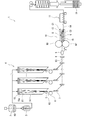
- tow band manufacturing apparatus It is the schematic of the tow band manufacturing apparatus which concerns on 1st Embodiment. It is a schematic cross-sectional view of the tow band manufactured by the tow band manufacturing apparatus of FIG. It is the schematic of the textile article manufacturing apparatus which concerns on 1st Embodiment. It is a schematic cross-sectional view of the tow band carried between the 1st spread fiber pair and the 2nd spread fiber roll pair of FIG. It is sectional drawing of the textile article manufactured by the textile article manufacturing apparatus of FIG. It is the schematic of the tow band manufacturing apparatus which concerns on the modification of 1st Embodiment. It is the schematic of the tow band manufacturing apparatus which concerns on 2nd Embodiment.
- the method for producing a textile article according to the first embodiment includes an attachment step in which a plurality of resin granules made of a fibrous polymer are attached to the first fiber while transporting a plurality of the first fibers, and the plurality.
- the first treatment step of applying an external force to the plurality of first fibers impregnated with the resin granules so as to reduce the fiber gaps, and the plurality of fibers impregnated with the plurality of resin granules.
- a second fiber having an outer diameter smaller than that of the first fiber and set to a value in the range of 30 nm or more and 1.0 ⁇ m or less is formed from the plurality of resin granules. It has a second treatment step of forming a fiber composite containing the first fiber and the second fiber.
- the external force is applied to the plurality of first fibers by crimping the plurality of first fibers.
- FIG. 1 is an overall view of the tow band manufacturing apparatus 1 according to the first embodiment.
- the tow band manufacturing apparatus 1 shown in FIG. 1 spins the filament 61, which is the first fiber, by a dry spinning method. Further, the tow band manufacturing apparatus 1 manufactures a yarn 62, an end 63, and a tow band 64 by using a plurality of filaments 61.
- the raw material of the filament 61 may be any material as long as the yarn 62, the end 63, and the toe band 64 can be appropriately obtained by, for example, the spinning method to be selected.
- the filament 61 of the present embodiment comprises at least one of rayon, polypropylene, polyethylene terephthalate, polyethylene, and cellulose acetate. As an example, the filament 61 is made of cellulose acetate.
- the tow band manufacturing apparatus 1 includes a mixing apparatus 2, a filtration apparatus 3, a spinning unit 4, an oil agent attachment unit 5, a godette roll 6, a guide pin 7, an attachment device 8, a first drying device 9, a crimping device 10, and a second drying device. 11 is provided.
- a predetermined spinning stock solution 60 is used.
- the spinning stock solution 60 is formed by dissolving flakes such as cellulose diacetate in an organic solvent at a predetermined concentration.
- the spinning stock solution 60 is mixed by the mixing apparatus 2 and then filtered by the filtering apparatus 3.
- the spinning stock solution 60 that has passed through the filtration device 3 is discharged from a plurality of spinning holes 15a of the spinning spout 15 provided on the spinning cylinder 14 of the spinning unit 4.
- the spinning hole 15a has a predetermined peripheral shape (circular as an example).
- the diameter of the spinning hole 15a is appropriately set according to the single fineness (FD) of the filament 61 after production.
- the spinning stock solution 60 discharged from each spinning hole 15a is heated by hot air supplied into the spinning cylinder 14 from a drying unit (not shown) and dried by evaporating the organic solvent. As a result, the solid filament 61 is formed.
- a plurality of filaments 61 that have passed through one spinning cylinder 14 are focused by a guide pin 7 to form a yarn 62.
- the yarn 62 is wound by a godet roll 6 after being impregnated with a fiber oil agent by the oil agent impregnation unit 5.
- the yarn 62 is then picked up by a predetermined take-up device.
- a series of units for producing the yarn 62 that is, a winding unit having a spinning unit 4, a drying unit, an oil-impregnated unit 5, and a godet roll 6 for discharging a spinning stock solution 60 from a spinning cap 15 to spin a filament 61.
- a station Also called a station. Normally, a plurality of stations are arranged side by side in a row.
- the plurality of yarns 62 that have passed through each station are transported along the arrangement direction of the stations, and are sequentially accumulated or stacked. As a result, the plurality of yarns 62 are converged to form an end (toe) 63 which is a flat aggregate of the yarns 62.
- the end 63 is obtained by converging a plurality of yarns 62 and setting them to a predetermined total fineness (TD). The end 63 is conveyed and guided to the attachment device 8.
- the spinning method of the filament 61 is not limited, and a method other than the dry spinning method (for example, a melt spinning method or a wet spinning method) may be used.
- the spinning method of the filament 61 may be any method as long as the toe band 64 can be appropriately obtained.
- the attachment device 8 attaches a dispersion liquid containing the resin granules 66 to the filament 61 while conveying a plurality of first fibers (here, the end 63).
- the attachment device 8 has a storage unit for storing the dispersion liquid, and an attachment roll pivotally supported so that the dispersion liquid in the storage unit is attached to the peripheral surface and attached to the filament 61.
- the dispersion liquid of the present embodiment is an aqueous dispersion liquid in which a plurality of resin granules 66 are dispersed in water.
- the dispersion liquid may contain a liquid other than water.
- the resin granular material 66 contains a lamellar structure.
- the lamellar structure referred to here refers to a structure in which polymer chains constituting the resin of the resin granular material 66 are connected and folded.
- the lamellar structure contained in the resin granular material 66 is specifically a fine fiber formed by connecting the polymer chains in a ribbon shape in millions of units. The fine fibers are folded and stored inside the resin granular material 66.
- the resin granules 66 are primary particles, and a plurality of resin granules 66 are bonded to each other to form secondary particles.
- the secondary particles in other words, the two bonded resin granules 66
- fine fibers are pulled out from the resin granules 66 and from the resin granules 66.
- Resin fibers 66a are formed.
- the dispersion liquid of the present embodiment contains primary particles composed of a plurality of resin granules 66 in a state of being dispersed in a solvent.
- the attachment device 8 adheres the dispersion liquid to the filament 61
- the plurality of resin granules 66 are dispersed and attached to the surface of the filament 61.
- the plurality of resin granules 66 adhered to the surfaces of the different filaments 61 adhere to each other. Further, by relaxing the external force applied to the plurality of filaments 61, the adhered resin granules 66 are separated from each other to form the resin fiber 66a.
- the resin granule 66 of the present embodiment may be, for example, one that is produced by a polymerization reaction and contains a lamellar structure.
- the resin granular material 66 is composed of, for example, at least one of PTFE (polytetrafluoroethylene), polypropylene, polyethylene, and polyamide.
- the resin granular material 66 is made of PTFE as an example.
- the resin granule 66 is set here to have an average particle size in the range of 100 nm or more and 100 ⁇ m or less (for example, about 300 nm).
- the average particle size is more preferably in the range of 200 nm or more and 700 nm or less, and further preferably in the range of 250 nm or more and 400 nm or less.
- the average particle size refers to the median diameter (cumulative 50% diameter (D50)) calculated from the measurement result by the dynamic light scattering method.
- the resin granule 66 is molded by paste extrusion molding as an example.
- the first drying device 9 dries at least a part of the dispersion liquid impregnated on the filament 61.
- the crimping device 10 crimps the filament 61.
- the crimping device 10 has a pair of nip rolls N1 and N2 and a stuffing box 18.
- the pair of nip rolls N1 and N2 are arranged with their rotation axes parallel to each other.
- the pair of nip rolls N1 and N2 press the end 63 between the peripheral surfaces of each other.
- the stuffing box 18 is arranged behind the pair of nip rolls N1 and N2 in the transport direction P.
- the stuffing box 18 has a pair of plate members C1 and C2 having plate surfaces extending in the transport direction P, and an urging member 12.
- the pair of plate members C1 and C2 are arranged so that the plate surfaces face each other with a gap G so that the gap G decreases from the front to the rear of the stuffing box 18 in the transport direction P. Ends 63 (a plurality of filaments 61) that have passed through the pair of nip rolls N1 and N2 are conveyed in the gap G.
- the urging member 12 is a plate material as an example, and extends along the plate surface of the plate material C1 in a direction perpendicular to the transport direction P.
- the front end of the urging member 12 in the transport direction P is rotatably supported by the plate member C1 around an axis Q extending in a direction perpendicular to the transport direction P along the plate surface of the plate member C1.
- the urging member 12 is urged toward the plate surface of the plate material C2 and presses the end 63 conveyed between the pair of plate materials C1 and C2.
- the end 63 is pressed by the pair of nip rolls N1 and N2 between the pair of nip rolls N1 and N2, and then pushed into the stuffing box 18.
- the end 63 is pressed against the plate surface of the plate material C2 by the urging member 12 while meandering and being conveyed between the plate surfaces of the plate materials C1 and C2.
- the end 63 is pushed into the stuffing box 18 by a pair of nip rolls N1 and N2 with a force larger than the force received by the plate members C1 and C2 and the urging member 12, so that the end 63 is crimped.
- the toe band 64 is formed by the end 63 passing through the crimping device 10.
- the plurality of filaments 61 in the end 63 are pressed by the crimping device 10 to reduce the fiber gaps, and the plurality of resin granules 66 attached to the filament 61 are bonded to each other. As a result, secondary particles of the resin granule 66 are formed.
- the nip pressures of the pair of nip rolls N1 and N2 are set to values in an appropriate pressure range in order to appropriately crimp the filament 61 and reduce the amount of the dispersion liquid falling off from the filament 61. It is desirable to do.
- the tow band 64 that has passed through the crimping device 10 is further dried by the second drying device 11.
- FIG. 2 is a schematic cross-sectional view of the tow band 64 manufactured by the tow band manufacturing apparatus 1 of FIG.
- the tow band 64 has a plurality of crimped filaments 61 and a plurality of resin granules 66 dispersed inside the tow band 64 and supported on the filament 61.
- the surface of the filament 61 is partially covered with a plurality of resin granules 66.
- the plurality of resin granules 66 are supported on the filament 61 in a state of being bonded to each other.
- the toe band 64 is formed bulky.
- the TD and FD of the toe band 64 can be set as appropriate.
- the FD of the toe band 64 is set to a value in the range of 1.0 or more and 10.0 or less. From the viewpoint of appropriately securing fiber gaps while maintaining an appropriate strength of the filament 61, it is desirable that the FD of the toe band 64 is further set to a value in the range of 2.0 or more and 6.0 or less.
- the tow band 64 that has passed through the second drying device 11 is compressed and packed in a packing container 19 after being accumulated to form a veil.
- the packing container 19 of FIG. 1 shows a cross-sectional structure.
- PTFE used as a material for resin granules 66 Next, PTFE used as a material for the resin granule 66 will be described.
- This PTFE is configured as a fibrous polymer.
- Such PTFE is, for example, high molecular weight PTFE obtained from emulsion polymerization or suspension polymerization of TFE (tetrafluoroethylene).
- the high molecular weight PTFE may be at least one of modified PTFE and homo-PTFE.
- Modified PTFE is composed of TFE and a monomer (modified monomer) other than TFE.
- the modified PTFE is generally modified uniformly with a modified monomer or modified at the initial stage or the final stage of the polymerization reaction, but is not particularly limited.
- Modified PTFE includes a TFE unit based on TFE and a modified monomer unit based on a modified monomer.
- the modified monomer unit is a part of the molecular structure of the modified PTFE and is a portion derived from the modified monomer.
- the total monomer unit is derived from all the monomers in the molecular structure of the modified PTFE.
- the modified monomer is not particularly limited as long as it can be copolymerized with TFE.
- the "high molecular weight" of the high molecular weight PTFE referred to here is a molecular weight at which fibrils that are easily fibrous during the production of tow band 64 and have a long fiber length can be obtained, and have a standard specific gravity (SSG) of 2.130 or more and 2.230. It is a value in the following range, and indicates a molecular weight that does not substantially melt and flow due to its high melt viscosity.
- SSG standard specific gravity
- FIG. 3 is an overall view of the textile article manufacturing apparatus 20 according to the first embodiment.
- the packing container 19 of FIG. 3 shows a cross-sectional structure.
- the textile article manufacturing apparatus 20 includes a convergence ring 21, a first spreader unit 22, a turn baffle 23, a second spreader unit 24, a pretension roll pair 25, and a first spreader roll. It includes a pair 26, a second spread roll pair 27, a third fiber spread unit 28, a transport roll pair 29, and a take-up roll 30.
- the converging ring 21 and the turn baffle 23 guide the bale-shaped tow band 64 carried up from the inside of the packing container 19 to the first opening unit 22 side.
- the first fiber-spreading unit 22, the second fiber-spreading unit 24, and the third fiber-spreading unit 28 open the tow band 64 in the width direction with a gas (pressurized air as an example).
- the pretension roll pair 25, the first spread fiber pair 26, and the second spread fiber roll pair 27 open the toe band 64 in the width direction and the transport direction P with tension applied to the tow band 64 in the transport direction P. Weave.
- the pretension roll pair 25 has a pair of rolls R1 and R2 arranged so as to face the peripheral surfaces.
- the first spread fiber pair 26 has a pair of rolls R3 and R4 arranged so as to face the peripheral surfaces.
- the second spread fiber pair 27 has a pair of rolls R5 and R6 arranged so as to face the peripheral surfaces.
- a groove extending in the circumferential direction is formed on the peripheral surface of the rolls R3 to R6 so that the toe band 64 can be easily opened.
- the transport roll pair 29 has a pair of rolls R7 and R8 arranged so as to face each other on the peripheral surfaces.
- the transport roll pair 29 transports the tow band 64 that has passed through the second spread fiber pair 27 to the take-up roll 30 side.
- the take-up roll 30 winds up the toe band 64 that has passed through the transport roll pair 29.
- the tow band 64 carried up from the inside of the packing container 19 is inserted into the convergence ring 21, and then the fiber is opened in the width direction by the first fiber opening unit 22. After that, the tow band 64 is guided to the second opening unit 24 side by the turn baffle 23.
- the tow band 64 is further opened in the width direction by the second opening unit 24, and then inserted in this order between the rolls R1 and R2, between the rolls R3 and R4, and between the rolls R5 and R6.
- the toe band 64 comes into contact with the rolls R1 to R6.
- the rotation speed of the pair of rolls R5 and R6 is faster than the rotation speed of the pair of rolls R3 and R4.
- the tow band 64 is opened in the transport direction P and the width direction by the first spread roll pair 26 and the second spread roll pair 27 while applying tension in the transport direction P.
- FIG. 4 is a schematic cross-sectional view of the tow band 64 conveyed between the first spread fiber pair 26 and the second spread fiber pair 27 of FIG.
- the tow band 64 is opened in the transport direction P (horizontal direction of the paper surface) and the width direction (vertical direction of the paper surface) by the roll pairs 26 and 27, whereby the filament 61 and the resin granule 66 Tension acts on the transport direction P and the width direction.
- the plurality of filaments 61 in the tow band 64 are opened.
- tension acts on the resin granules 66 so as to separate the resin granules 66 that are bonded to each other, so that the fine fibers folded in the resin granules 66 are efficiently pulled. It is stretched to form resin fibers 66a. As a result, the tow band 64 becomes a fiber composite 67 containing the filament 61 and the resin fiber 66a.
- the resin fiber 66a can be formed by utilizing the tension applied to the toe band 64 at the time of opening the fiber. Therefore, a dedicated process or equipment for separately forming the resin fiber 66a is unnecessary.
- the resin fiber 66a was formed when the tow band 64 was opened, but the resin fiber 66a is such that the fiber gap is reduced with respect to the plurality of filaments 61 to which the plurality of resin granules 66 are attached. It is formed by applying an external force and then relaxing this external force. In the present embodiment, the resin fiber 66a is formed by applying the external force to the plurality of filaments 61 at least once after the dispersion liquid is attached by the attachment device 8 and then relaxing the external force.
- the resin fiber 66a can also be formed by applying the nip pressure as the external force.
- at least one of the above-mentioned external forces may be used.
- the outer diameter of the resin fiber 66a can be adjusted by, for example, the tension applied to the toe band 64 when the toe band 64 is opened. For example, when the tension is increased, the outer diameter of the resin fiber 66a can be set small, and the length dimension of the resin fiber 66a can be set long. When the tension is reduced, the outer diameter of the resin fiber 66a can be set large, and the length dimension of the resin fiber 66a can be set short.
- the outer diameter of the resin fiber 66a can be set to a value in the range of 30 nm or more and 1.0 ⁇ m or less.
- the fiber composite 67 that has passed between the second spread fiber pairs 27 is inserted between the rolls R7 and R8 of the transport roll pairs 29.
- the rotation speed of the pair of rolls R7 and R8 is slower than the rotation speed of the pair of rolls R5 and R6.
- the tension acting on the fiber composite 67 between the first spread roll pair 26 and the second spread roll pair 27 in the transport direction P is increased between the second spread roll pair 27 and the transport roll pair 29. It is relaxed between and. By relaxing this tension, the fiber composite 67 is adjusted to be bulky.
- FIG. 5 is a cross-sectional view of the textile article 65 manufactured by the textile article manufacturing apparatus 20 of FIG.
- the resin fiber 66a is supported on the filament 61 while being entangled with the filament 61. Therefore, even when the resin fiber 66a is thinner than the filament 61, the resin fiber 66a can be supported on the filament 61 while preventing the resin fiber 66a from being cut. Therefore, the function of the resin fiber 66a can be maintained for a long period of time.
- the resin fibers 66a are arranged so as to diffuse throughout the inside of the toe band 64. In the fiber article 65, there may be a portion where the resin granular material 66 is reduced or a portion where the resin granular material 66 disappears due to the formation of the resin fiber 66a.
- the fiber article 65 is formed bulky by a plurality of opened filaments 61 with abundant fiber gaps inside. Therefore, the textile article 65 has a soft and good tactile sensation.
- the textile article 65 is in the form of a sheet as an example.
- the fiber article 65 may be formed by stacking and crimping a plurality of sheet-shaped fiber composites 67. In this case, for example, by adjusting the number of fiber composites 67, it is possible to easily design the thickness dimension of the fiber article 65. Further, the fiber article 65 may be formed by arranging a plurality of sheet-shaped fiber composites 67 in the width direction. In this case, for example, the width dimension of the fiber article 65 can be easily designed by adjusting the number of fiber composites 67.
- the value of the external force applied to the plurality of filaments 61 for forming the resin fiber 66a can be appropriately set, and for example, a value of 0.05 MPa or more can be exemplified.
- the value of the external force applied to the plurality of filaments 61 is, for example, a value of 0.10 Mpa or more in order to obtain good filter performance.
- the upper limit of the external force may be, for example, a value of 1 MPa or more (for example, several tens of MPa or more).
- the textile article 65 is manufactured by a manufacturing method using the tow band manufacturing apparatus 1 and the textile article manufacturing apparatus 20.
- This manufacturing method includes an attachment step, a first treatment step, and a second treatment step. Further, the production method of the present embodiment further includes a drying step.
- a plurality of resin granules 66 made of a fibrous polymer in this embodiment, a plurality of resin granules 66 containing a lamellar structure and bonded to each other are formed.
- This is a step of adhering the containing dispersion liquid) to the filament 61.
- the first treatment step is a step of applying an external force to the plurality of filaments 61 to which the plurality of resin granules 66 are attached so that the fiber gaps are reduced.
- the toe band 64 is formed by applying an external force to the filament 61 to which the plurality of resin granules 66 are added and crimping the filament 61. Further, as an example, in the first treatment step, while transporting the tow band 64, tension is applied to the plurality of filaments 61 to which the plurality of resin granules 66 in the tow band 64 are attached as the external force in the transport direction P. To do.
- a nip pressure set to a value of 0.05 MPa or more is further applied as the external force to the plurality of filaments 61 to which the plurality of resin granules 66 are attached.
- This nip pressure is, as an example, applied by at least one (all here) of a pair of nip rolls N1, N2, a first spread roll pair 26, and a second spread roll pair 27. As a result, abundant resin fibers 66a are formed.
- the resin fibers 66a are formed from the plurality of resin granules 66 by relaxing the external force applied to the plurality of filaments 61 to which the resin granules 66 are attached, and the filaments 61 and the resin fibers 66a are formed. It is a step of forming a fiber composite 67 containing.
- the drying step is a step of drying at least a part of the dispersion liquid adhered to the filament 61 between the impregnation step and the first treatment step.
- the dispersion liquid desorbed from the filament 61 in the first treatment step is recovered, and the recovered dispersion liquid is used in the attachment step.
- the weight ratio W1 / W2 of the total weight W1 of the filament 61 and the total weight W2 of the resin fibers 66a and the residual resin granules 66 can be appropriately set.
- the fiber composite 67 in which the weight ratio W1 / W2 is set to a value in the range of 3.00 or more and 200.00 or less is formed.
- the resin fiber 66a can be stably supported on the support made of the filament 61, and the function of the resin fiber 66a can be easily exerted.
- the weight ratio W1 / W2 includes a value in the range of 9.00 or more and 200 or less.
- the range of the weight ratio W1 / W2 corresponds to a value in the range of 0.5% or more and 10% or less of the adhesion concentration of PTFE of the fiber composite 67 when the resin granular material 66 is composed of PTFE.
- the filament 61 whose outer diameter is set to a value in the range of 5 ⁇ m or more and 50 ⁇ m or less is used. As a result, the degree of freedom in designing the textile article can be improved.
- the weight ratio W1 / W2 By setting the weight ratio W1 / W2 to a value in the above range, the total volume V1 of the filament 61 (first fiber), the resin fiber 66a (second fiber), and the remaining resin granules 66 are combined.
- the maximum value of the volume ratio V1 / V2 with the volume V2 is 124.0 or less. As a result, it is possible to facilitate the function of the resin fiber 66a while appropriately securing the fiber gap inside the fiber article 65 and stably holding the resin fiber 66a by the filament 61.
- the length dimension of the filament 61 and the length dimension of the resin fiber 66a can be appropriately set.
- the fiber composite 67 in which the length dimension of the filament 61 is longer than the length dimension of the resin fiber 66a is formed.
- the filament 61 can be used as the skeleton of the fiber article 65, and the resin fiber 66a can be supported on the filament 61 so that the function of the resin fiber 66a can be stably exhibited.
- the outer diameter is set to a value in the range of 30 nm or more and 1.0 ⁇ m or less, and the ultrafine resin fiber 66a and the outer diameter are set.
- the ultrafine resin fiber 66a and the outer diameter are set.
- the ultrafine resin fiber 66a with the filament 61 and supporting the resin fiber 66a with the filament 61 it is possible to manufacture the fiber article 65, which is bulkier than the case where the fiber article is manufactured only with the resin fiber, and for a long period of time. It is possible to manufacture a fiber article 65 capable of exhibiting the functions of the resin fiber 66a.
- the resin fiber 66a can be uniformly dispersed and arranged in the fiber article 65, and the fiber has uniform quality.
- Article 65 can be manufactured.
- the textile article 65 can be efficiently and continuously manufactured by a single transport facility.
- the individual steps for forming the resin fiber 66a can be omitted, the manufacturing process can be simplified, and the manufacturing cost can be reduced.
- a bulky textile article 65 having high functionality can be efficiently produced.
- the toe band 64 is formed by applying the external force to the filament 61 to which the plurality of resin granules 66 are added and crimping the filament 61.
- the fiber article 65 including the filament 61 and the resin fiber 66a can be efficiently produced while using the tow band 64.
- tension is applied to the toe band 64 as the external force in the transport direction while the toe band 64 is being conveyed.
- the external force can be efficiently applied to the filament 61 in the first treatment step.
- a dispersion liquid in which a plurality of resin granules 66 are dispersed is used.
- the dispersion liquid in this way, it is possible to easily attach the plurality of resin granules 66 to a wide range of the surface of the filament 61 by utilizing the fluidity of the dispersion liquid.
- the above-mentioned production method has a drying step, the amount of the resin granules 66 falling off from the filament 61 can be reduced by drying a part of the dispersion liquid before forming the tow band 64, and the filament 61 and the resin fiber can be reduced.
- the weight ratio with 66a can be easily adjusted.
- the resin granules 66 can be appropriately adhered to the filament 61 to promote the formation of the resin fibers 66a in the second treatment step.
- the dispersion can be produced at a relatively low cost and the dispersion can be easily handled. Further, in the attachment step, the dispersion liquid desorbed from the filament 61 in the first treatment step is reused, so that the manufacturing cost can be further reduced.
- a nip pressure set to a value of 0.05 MPa or more is applied as the external force to the plurality of filaments 61 to which the plurality of resin granules 66 are attached.
- a plurality of resin granules 66 having a lamellar structure are used.
- the resin fiber 66a can be easily formed from the plurality of resin granules 66 in the second treatment step.
- a filament 61 composed of at least one of rayon, polypropylene, polyethylene terephthalate, polyethylene, and cellulose acetate may be used.
- a resin granular material 66 composed of at least one of polytetrafluoroethylene, polypropylene, polyethylene, and polyamide may be used.
- the fiber article 65 containing the filament 61 and the resin fiber 66a can be efficiently produced, and by combining the filament 61 made of a specific material and the resin fiber 66a, the filament 61 and the resin fiber 66a can be obtained. It is possible to make it easier to exert each function of.
- the external force applied to the plurality of filaments 61 is applied to the plurality of filaments at a timing other than when the filaments 61 are crimped or when the tow band containing the crimped filaments 61 is opened. It may be a force applied to the filament 61.
- FIG. 6 is a schematic view of the tow band manufacturing apparatus 101 according to the modified example of the first embodiment.
- the tow band manufacturing apparatus 101 omits the attachment apparatus 8 and the first drying apparatus 9, and instead includes a granular material adding apparatus (feeder) 16.
- the granular material adding device 16 keeps the resin granular material 66 on the filament 61 in powder form on the spinning cylinder 14 side (here, between the godet roll 6 in the transport direction P and the crimping device 10) with respect to the crimping device 10. Arranged so that it can be added.
- a plurality of powdery resin granules 66 are directly attached to the filament 61.
- water or a fiber oil agent is usually impregnated on the filament 61 introduced into the crimping device 10.
- the resin granules 66 adhere well to the surface of the filament 61.
- a plurality of resin granules 66 can be attached to the filament 61 by a relatively simple method.
- the second embodiment will be described focusing on the differences from the first embodiment.
- FIG. 7 is a schematic view of the textile article manufacturing apparatus 201 according to the second embodiment.
- a veil-shaped toe band 164 that does not contain resin granules 66 and is not crimped is used.
- the toe band 164 is compressed and packed in a packing container 119.
- the textile article manufacturing apparatus 201 is a plurality of guide members (as an example, guide rolls R9 to R16) arranged so as to guide the tow band 164 unwound from the packing container 119 in the transport direction P. ), An adhering device 108 for adhering the dispersion liquid to the tow band 164 to be conveyed, a pair of nip rolls N4 and N5 for passing the tow band 164 impregnated with the dispersion liquid to the nip point N3, and a toe band passing through the nip rolls N4 and N5.
- a drying device 131 for drying 164 (fiber composite 67) is provided.
- the toe band 164 is guided by the guide roll R12 and immersed in the dispersion solution based on the dip coating method, so that the dispersion solution is attached.
- the tow band 164 to which the dispersion liquid is attached by the attachment device 108 and dried by the drying device 31 is once compressed and packed in another packing container 120.
- the textile article manufacturing apparatus 201 widens the first fiber opening unit 22 that widens the tow band 164 unwound from the packing container 120, the turn baffle 123 that guides the toe band 164, and the toe band 164 that has passed through the turn baffle 123.
- the two fiber-spreading unit 24 and a pair of nip rolls N7 and N8 for passing the tow band 164 that has passed through the second fiber-spreading unit 24 to the nip point N6 are provided.
- the tow band 164 impregnated with the plurality of resin granules 66 passes through the nip points N3 of the nip rolls N4 and N5 so that the fiber gaps are reduced with respect to the plurality of filaments 61.
- External force nip pressure
- the external force applied to the filament 61 is relaxed.
- a large number of resin granules 66 are dispersed and adhered to the surfaces of the plurality of filaments 61 in the fiber gaps, and the fiber gaps are reduced by an external force, so that the resin granules adhered to the surfaces of different filaments 61. 66 are bonded to each other.
- the resin fibers 66a are formed from the resin granules 66 attached to the filament 61 of the toe band 164, and the fiber composite 67 is formed.
- the resin fiber 66a is also formed by passing through the nip points N6 of the nip rolls N7 and N8.
- the fiber composite 67 is wound on a predetermined winding roll 30.
- the fiber article 65 is obtained by cutting the wound fiber composite 67 to a predetermined size.
- the first treatment step a plurality of filaments 61 are inserted between the pair of nip rolls N4 and N5 and pressed by the pair of nip rolls N4 and N5. An external force is applied to the filament 61 to which the resin granular material 66 is attached.
- the textile article 65 can also be efficiently produced by such a method. Further, according to the present embodiment, since the fiber article 65 using the filament 61 which is not crimped can be obtained, the degree of freedom in designing the fiber article 65 can be improved.
- the nip rolls N4 and N5 and the nip rolls N7 and N8 may be omitted.
- the resin fiber 66a could not be formed in Comparative Example 1, while the resin fiber 66a could be formed in any of Examples 1 to 7. Further, when the fiber articles 65 of Examples 1 to 7 were magnified and observed, the fiber articles 65 of Examples 5 to 7 had a wider range of resin fibers 66a as compared with the fiber articles 65 of Examples 1 to 4. It was confirmed that it was formed. From this, it is possible to easily manufacture the fiber article 65 in which the abundant resin fibers 66a are widely distributed, for example, by performing the first treatment step at a plurality of timings at the time of manufacturing the fiber article 65. Conceivable.
- the step of packing the tow band 64 manufactured by the tow band manufacturing apparatus 1, 101 in the packing container 19 is shown, but the tow band 64 is introduced into the textile article manufacturing apparatus 20 without being packed, and the textile article is introduced. 65 may be manufactured.
- the configuration of the textile article manufacturing apparatus 20 is not limited to the above.
- a slurry containing a relatively large amount of resin granules 66 may be used as the dispersion liquid used in the attachment step. Further, the resin granule 66 may be attached to the filament 61 before forming the yarn 62 or the end 63.
Landscapes
- Engineering & Computer Science (AREA)
- Textile Engineering (AREA)
- Mechanical Engineering (AREA)
- Yarns And Mechanical Finishing Of Yarns Or Ropes (AREA)
- Treatments For Attaching Organic Compounds To Fibrous Goods (AREA)
- Nonwoven Fabrics (AREA)
Abstract
A method for producing fiber articles comprising: an attachment step for conveying multiple first fibers while attaching multiple resin particles comprising a polymer that is capable of forming fibers to the first fibers; a first treatment step for applying an external force on the multiple first fibers to which the multiple resin particles have been attached so that the gaps between fibers are reduced; and a second treatment step for forming second fibers with an outside diameter smaller than that of the first fibers and set to a value in the range of 30 nm to 1.0 μm, from the multiple resin particles by easing the external force applied on the multiple first fibers to which the multiple resin particles were attached and forming a fiber composite comprising the first and second fibers.
Description
本開示は、繊維物品の製造方法に関する。
This disclosure relates to a method for manufacturing textile articles.
繊維物品は、例えば、流体中から不純物を濾過する濾過部材や、衛生用品等の吸収性部材として用いられる。特許文献1には、異なる種類の繊維を含む繊維物品である不織布が開示されている。本文献には、各種類の繊維を個別に紡糸且つ搬送しながら、一方の繊維の繊維流を他方の繊維の繊維流に挿入することで不織布を製造する製造方法が開示されている。
Textile articles are used, for example, as filtration members for filtering impurities from fluids and absorbent members for sanitary goods and the like. Patent Document 1 discloses a non-woven fabric which is a textile article containing different types of fibers. The present document discloses a manufacturing method for producing a non-woven fabric by inserting the fiber flow of one fiber into the fiber flow of the other fiber while spinning and transporting each type of fiber individually.
異なる種類の繊維を含む繊維物品では、例えば、外径が異なる繊維を組み合わせて嵩高にすることで、各繊維が有する機能をそれぞれ発現させ、繊維物品の性能を向上できる。しかしながら、このような高機能性を有する繊維物品を効率よく製造することは困難な場合がある。この問題は、特に、外径が極細の繊維を用いる場合に顕著となる。
In a fiber article containing different types of fibers, for example, by combining fibers having different outer diameters to make them bulky, the functions of each fiber can be exhibited and the performance of the fiber article can be improved. However, it may be difficult to efficiently produce a textile article having such high functionality. This problem becomes remarkable especially when a fiber having an extremely fine outer diameter is used.
そこで本開示は、外径が異なる種類の繊維を組み合わせてなる繊維物品を製造する場合において、高機能を有する嵩高な繊維物品を効率よく製造可能にすることを目的とする。
Therefore, an object of the present disclosure is to make it possible to efficiently produce a bulky textile article having high functionality in the case of producing a textile article formed by combining different types of fibers having different outer diameters.
上記課題を解決するために、本開示の一態様に係る繊維物品の製造方法は、複数本の第1繊維を搬送しながら、繊維化可能な高分子からなる複数の樹脂粒状物を、前記第1繊維に添着する添着ステップと、前記複数の樹脂粒状物を添着された前記複数本の第1繊維に対し、繊維間隙が縮小するように外力を付与する第1処理ステップと、前記複数の樹脂粒状物を添着された前記複数本の第1繊維に付与した前記外力を緩和することにより、前記複数の樹脂粒状物から外径が前記第1繊維よりも小さく且つ30nm以上1.0μm以下の範囲の値に設定された第2繊維を形成し、前記第1繊維と前記第2繊維とを含む繊維複合体を形成する第2処理ステップと、を有する。
In order to solve the above problems, in the method for producing a fiber article according to one aspect of the present disclosure, a plurality of resin granules made of a fibrous polymer are produced while carrying a plurality of first fibers. An attachment step of adhering to one fiber, a first treatment step of applying an external force to the plurality of first fibers to which the plurality of resin granules are attached so as to reduce fiber gaps, and the plurality of resins. By relaxing the external force applied to the plurality of first fibers impregnated with the granules, the outer diameter of the plurality of resin granules is smaller than that of the first fibers and is in the range of 30 nm or more and 1.0 μm or less. It has a second treatment step of forming a second fiber set to the value of and forming a fiber composite containing the first fiber and the second fiber.
上記方法によれば、上記各ステップを行うことで、外径が30nm以上1.0μm以下の範囲の値に設定された極細の第2繊維と、外径が第2繊維よりも太い第1繊維とを含む嵩高な繊維物品を製造できる。また、極細の第2繊維を第1繊維と組み合わせ、第2繊維を第1繊維で支持することにより、例えば第2繊維のみで繊維物品を製造した場合に比べて嵩高な繊維物品を製造できると共に、長期にわたり第2繊維の機能を発揮可能な繊維物品を製造できる。また、例えば第1繊維に分散して添着した複数の樹脂粒状物により第2繊維を形成することで、繊維物品内に第2繊維を均一に分散して配置でき、均一な品質を有する繊維物品を製造できる。
According to the above method, by performing each of the above steps, the ultrafine second fiber whose outer diameter is set to a value in the range of 30 nm or more and 1.0 μm or less and the first fiber whose outer diameter is thicker than the second fiber. A bulky textile article including and can be produced. Further, by combining the ultrafine second fiber with the first fiber and supporting the second fiber with the first fiber, it is possible to manufacture a bulky fiber article as compared with the case where the fiber article is manufactured only with the second fiber, for example. , It is possible to manufacture a textile article capable of exhibiting the function of the second fiber for a long period of time. Further, for example, by forming the second fiber with a plurality of resin granules dispersed and adhered to the first fiber, the second fiber can be uniformly dispersed and arranged in the fiber article, and the fiber article has uniform quality. Can be manufactured.
また、上記各ステップを行うことで、上記繊維物品を単一の搬送設備で効率よく連続的に製造できる。これにより、第2繊維を形成するための個別の工程を省略でき、製造工程を簡素化して、製造コストを低減できる。結果として、高機能を有する嵩高な繊維物品を効率よく製造できる。
Further, by performing each of the above steps, the above-mentioned textile articles can be efficiently and continuously manufactured with a single transport facility. As a result, the individual steps for forming the second fiber can be omitted, the manufacturing process can be simplified, and the manufacturing cost can be reduced. As a result, a bulky textile article having high functionality can be efficiently produced.
前記第1処理ステップでは、前記複数の樹脂粒状物を添加された前記第1繊維に対して前記外力を付与して前記第1繊維を捲縮することによりトウバンドを形成してもよい。これにより、トウバンドを用いながら第1繊維及び第2繊維を含む繊維物品を効率よく製造できる。
In the first treatment step, a tow band may be formed by applying the external force to the first fiber to which the plurality of resin granules are added and crimping the first fiber. This makes it possible to efficiently produce a textile article containing the first fiber and the second fiber while using the tow band.
前記第1処理ステップでは、前記トウバンドを搬送しながら、前記トウバンド中の前記複数の樹脂粒状物を添着された前記複数本の第1繊維に対して、前記外力として張力を搬送方向に付与してもよい。また前記第1処理ステップでは、前記複数本の第1繊維を一対のニップロール間に挿通して前記一対のニップロールにより押圧することで、前記複数の樹脂粒状物を添着された前記第1繊維に対して前記外力を付与してもよい。これにより、第1処理ステップにおいて、第1繊維に外力を効率よく付与できる。
In the first treatment step, while transporting the tow band, tension is applied in the transport direction as the external force to the plurality of first fibers impregnated with the plurality of resin particles in the tow band. May be good. Further, in the first treatment step, the plurality of first fibers are inserted between the pair of nip rolls and pressed by the pair of nip rolls, whereby the plurality of resin granules are attached to the first fibers. The external force may be applied. As a result, an external force can be efficiently applied to the first fiber in the first treatment step.
前記添着ステップでは、前記複数の樹脂粒状物が分散された分散液を用いてもよい。このように分散液を用いることで、分散液の流動性を利用して、第1繊維の表面の広い範囲に複数の樹脂粒状物を添着し易くできる。
In the attachment step, a dispersion liquid in which the plurality of resin granules are dispersed may be used. By using the dispersion liquid in this way, it is possible to easily attach a plurality of resin granules to a wide range of the surface of the first fiber by utilizing the fluidity of the dispersion liquid.
前記添着ステップと前記第1処理ステップとの間で、前記第1繊維に添着された前記分散液の少なくとも一部を乾燥する乾燥ステップを更に有していてもよい。これにより、トウバンドを形成する前に分散液の一部を乾燥することで、第1繊維からの樹脂粒状物の脱落量を低減でき、第1繊維と第2繊維との重量比を調整し易くすることができる。また、第1繊維に樹脂粒状物を適切に添着させて、第2処理ステップでの第2繊維の形成を促進できる。
An additional drying step may be provided between the attachment step and the first treatment step to dry at least a part of the dispersion liquid attached to the first fiber. As a result, by drying a part of the dispersion liquid before forming the tow band, the amount of resin granules falling off from the first fiber can be reduced, and the weight ratio between the first fiber and the second fiber can be easily adjusted. can do. Further, the resin granules can be appropriately attached to the first fiber to promote the formation of the second fiber in the second treatment step.
前記分散液として、前記複数の樹脂粒状物を水に分散させた水分散液を用いてもよい。これにより、分散液を比較的安価に製造できると共に、分散液を扱い易くすることができる。
As the dispersion liquid, an aqueous dispersion liquid in which the plurality of resin granules are dispersed in water may be used. As a result, the dispersion can be produced at a relatively low cost, and the dispersion can be easily handled.
前記添着ステップでは、前記第1処理ステップにおいて前記第1繊維から脱離した前記分散液を再利用してもよい。これにより、製造コストを更に低減し易くすることができる。
In the attachment step, the dispersion liquid desorbed from the first fiber in the first treatment step may be reused. This makes it easier to further reduce the manufacturing cost.
前記添着ステップでは、粉体状の前記複数の樹脂粒状物を前記第1繊維に直接添着してもよい。これにより、比較的簡素な方法で、第1繊維に複数の樹脂粒状物を添着できる。
In the attachment step, the plurality of powdery resin granules may be directly attached to the first fiber. Thereby, a plurality of resin granules can be attached to the first fiber by a relatively simple method.
前記第1処理ステップでは、前記複数の樹脂粒状物を添着された前記複数本の第1繊維に対し、0.05MPa以上の値に設定されたニップ圧を前記外力として付与してもよい。このようにニップ圧を設定することで、第2繊維を適切に形成し易くできる。
In the first treatment step, a nip pressure set to a value of 0.05 MPa or more may be applied as the external force to the plurality of first fibers impregnated with the plurality of resin granules. By setting the nip pressure in this way, it is possible to facilitate the proper formation of the second fiber.
前記添着ステップでは、ラメラ構造を有する前記複数の樹脂粒状物を用いてもよい。これにより、第2処理ステップにおいて、複数の樹脂粒状物から第2繊維を形成し易くできる。
In the attachment step, the plurality of resin granules having a lamellar structure may be used. This makes it easier to form the second fiber from the plurality of resin granules in the second treatment step.
前記第2処理ステップでは、前記第1繊維の総重量W1と、前記第2繊維及び残留する前記樹脂粒状物を合わせた総重量W2との重量比W1/W2が3.00以上200.00以下の範囲の値に設定された前記繊維複合体を形成してもよい。これにより、第1繊維からなる支持体に第2繊維を安定して担持させ、第2繊維の機能を発揮させ易くすることができる。
In the second treatment step, the weight ratio W1 / W2 of the total weight W1 of the first fiber and the total weight W2 of the second fiber and the remaining resin granules combined is 3.00 or more and 200.00 or less. The fiber composite may be formed with a value in the range of. As a result, the second fiber can be stably supported on the support made of the first fiber, and the function of the second fiber can be easily exerted.
前記第2処理ステップでは、前記第1繊維の長さ寸法が、前記第2繊維の長さ寸法よりも長い前記繊維複合体を形成してもよい。これにより、例えば、第1繊維を繊維物品の骨格として用い、第1繊維に第2繊維を担持させて、第2繊維の機能を安定して発揮させることができる。
In the second treatment step, the fiber composite may be formed in which the length dimension of the first fiber is longer than the length dimension of the second fiber. Thereby, for example, the first fiber can be used as the skeleton of the fiber article, the second fiber can be supported on the first fiber, and the function of the second fiber can be stably exhibited.
前記添着ステップでは、外径が5μm以上50μm以下の範囲の値に設定された前記第1繊維を用いてもよい。これにより、繊維物品の設計自由度を向上できる。
In the attachment step, the first fiber whose outer diameter is set to a value in the range of 5 μm or more and 50 μm or less may be used. As a result, the degree of freedom in designing the textile article can be improved.
前記添着ステップでは、レーヨン、ポリプロピレン、ポリエチレンテレフタレート、ポリエチレン、セルロースアセテートのうちの少なくとも1つからなる前記第1繊維を用いてもよい。また前記添着ステップでは、ポリテトラフルオロエチレン、ポリプロピレン、ポリエチレン、ポリアミドのうちの少なくとも1つからなる前記樹脂粒状物を用いてもよい。
In the attachment step, the first fiber composed of at least one of rayon, polypropylene, polyethylene terephthalate, polyethylene, and cellulose acetate may be used. Further, in the attachment step, the resin granules composed of at least one of polytetrafluoroethylene, polypropylene, polyethylene and polyamide may be used.
上記方法によれば、第1繊維と第2繊維とを含む繊維物品を効率よく製造できると共に、それぞれ特定の材料からなる第1繊維と第2繊維とを組み合わせることで、第1繊維と第2繊維との各機能を発揮し易くさせることができる。
According to the above method, a fiber article containing the first fiber and the second fiber can be efficiently produced, and by combining the first fiber and the second fiber made of specific materials, the first fiber and the second fiber are combined. It is possible to facilitate each function with the fiber.
本開示の各態様によれば、外径が異なる種類の繊維を組み合わせてなる繊維物品を製造する場合において、高機能を有する嵩高な繊維物品を効率よく製造できる。
According to each aspect of the present disclosure, in the case of producing a textile article made by combining different types of fibers having different outer diameters, a bulky textile article having high functionality can be efficiently produced.
以下、各実施形態について図を参照して説明する。
(第1実施形態)
第1実施形態の繊維物品の製造方法は、複数本の第1繊維を搬送しながら、繊維化可能な高分子からなる複数の樹脂粒状物を、第1繊維に添着する添着ステップと、前記複数の樹脂粒状物を添着された前記複数本の第1繊維に対し、繊維間隙が縮小するように外力を付与する第1処理ステップと、前記複数の樹脂粒状物を添着された前記複数本の第1繊維に付与した前記外力を緩和することにより、前記複数の樹脂粒状物から外径が前記第1繊維よりも小さく且つ30nm以上1.0μm以下の範囲の値に設定された第2繊維を形成し、前記第1繊維と前記第2繊維とを含む繊維複合体を形成する第2処理ステップとを有する。この第1処理ステップを行うため、本実施形態では、複数本の第1繊維を捲縮することにより、複数本の第1繊維に前記外力を付与する。以下、この製造方法に用いるトウバンド製造装置及び繊維物品製造装置について説明する。 Hereinafter, each embodiment will be described with reference to the drawings.
(First Embodiment)
The method for producing a textile article according to the first embodiment includes an attachment step in which a plurality of resin granules made of a fibrous polymer are attached to the first fiber while transporting a plurality of the first fibers, and the plurality. The first treatment step of applying an external force to the plurality of first fibers impregnated with the resin granules so as to reduce the fiber gaps, and the plurality of fibers impregnated with the plurality of resin granules. By relaxing the external force applied to one fiber, a second fiber having an outer diameter smaller than that of the first fiber and set to a value in the range of 30 nm or more and 1.0 μm or less is formed from the plurality of resin granules. It has a second treatment step of forming a fiber composite containing the first fiber and the second fiber. In order to perform this first treatment step, in the present embodiment, the external force is applied to the plurality of first fibers by crimping the plurality of first fibers. Hereinafter, the tow band manufacturing apparatus and the textile article manufacturing apparatus used in this manufacturing method will be described.
[トウバンド製造装置]
図1は、第1実施形態に係るトウバンド製造装置1の全体図である。図1に示すトウバンド製造装置1は、乾式紡糸法により、第1繊維であるフィラメント61を紡糸する。またトウバンド製造装置1は、複数本のフィラメント61により、ヤーン62、エンド63、及びトウバンド64を製造する。フィラメント61の原料は、例えば選択しようとする紡糸方法でヤーン62、エンド63、及びトウバンド64が適切に得られるものであればよい。本実施形態のフィラメント61は、レーヨン、ポリプロピレン、ポリエチレンテレフタレート、ポリエチレン、セルロースアセテートのうちの少なくとも1つからなる。一例としてフィラメント61は、セルロースアセテートからなる。 [Toe band manufacturing equipment]
FIG. 1 is an overall view of the tow band manufacturing apparatus 1 according to the first embodiment. The tow band manufacturing apparatus 1 shown in FIG. 1 spins thefilament 61, which is the first fiber, by a dry spinning method. Further, the tow band manufacturing apparatus 1 manufactures a yarn 62, an end 63, and a tow band 64 by using a plurality of filaments 61. The raw material of the filament 61 may be any material as long as the yarn 62, the end 63, and the toe band 64 can be appropriately obtained by, for example, the spinning method to be selected. The filament 61 of the present embodiment comprises at least one of rayon, polypropylene, polyethylene terephthalate, polyethylene, and cellulose acetate. As an example, the filament 61 is made of cellulose acetate.
図1は、第1実施形態に係るトウバンド製造装置1の全体図である。図1に示すトウバンド製造装置1は、乾式紡糸法により、第1繊維であるフィラメント61を紡糸する。またトウバンド製造装置1は、複数本のフィラメント61により、ヤーン62、エンド63、及びトウバンド64を製造する。フィラメント61の原料は、例えば選択しようとする紡糸方法でヤーン62、エンド63、及びトウバンド64が適切に得られるものであればよい。本実施形態のフィラメント61は、レーヨン、ポリプロピレン、ポリエチレンテレフタレート、ポリエチレン、セルロースアセテートのうちの少なくとも1つからなる。一例としてフィラメント61は、セルロースアセテートからなる。 [Toe band manufacturing equipment]
FIG. 1 is an overall view of the tow band manufacturing apparatus 1 according to the first embodiment. The tow band manufacturing apparatus 1 shown in FIG. 1 spins the
トウバンド製造装置1は、混合装置2、濾過装置3、紡糸ユニット4、油剤添着ユニット5、ゴデットロール6、ガイドピン7、添着装置8、第1乾燥装置9、捲縮装置10、及び第2乾燥装置11を備える。
The tow band manufacturing apparatus 1 includes a mixing apparatus 2, a filtration apparatus 3, a spinning unit 4, an oil agent attachment unit 5, a godette roll 6, a guide pin 7, an attachment device 8, a first drying device 9, a crimping device 10, and a second drying device. 11 is provided.
トウバンド製造装置1では、所定の紡糸原液60が用いられる。紡糸原液60は、一例として、セルロースジアセテート等のフレークが、所定濃度で有機溶媒に溶解されてなる。トウバンド製造装置1の駆動時には、紡糸原液60は、混合装置2により混合された後、濾過装置3により濾過される。濾過装置3を通過した紡糸原液60は、紡糸ユニット4の紡糸筒14上に備えられた紡糸口金15が有する複数の紡糸孔15aから吐出される。
In the tow band manufacturing apparatus 1, a predetermined spinning stock solution 60 is used. As an example, the spinning stock solution 60 is formed by dissolving flakes such as cellulose diacetate in an organic solvent at a predetermined concentration. When the tow band manufacturing apparatus 1 is driven, the spinning stock solution 60 is mixed by the mixing apparatus 2 and then filtered by the filtering apparatus 3. The spinning stock solution 60 that has passed through the filtration device 3 is discharged from a plurality of spinning holes 15a of the spinning spout 15 provided on the spinning cylinder 14 of the spinning unit 4.
紡糸孔15aは、周縁形状が所定形状(一例として円形)に形成されている。紡糸孔15aの直径は、製造後のフィラメント61の単繊度(FD)に合わせて適宜設定される。各紡糸孔15aから吐出された紡糸原液60は、不図示の乾燥ユニットから紡糸筒14内に供給される熱風により加熱されて有機溶媒が蒸発することで乾燥する。これにより、固体のフィラメント61が形成される。
The spinning hole 15a has a predetermined peripheral shape (circular as an example). The diameter of the spinning hole 15a is appropriately set according to the single fineness (FD) of the filament 61 after production. The spinning stock solution 60 discharged from each spinning hole 15a is heated by hot air supplied into the spinning cylinder 14 from a drying unit (not shown) and dried by evaporating the organic solvent. As a result, the solid filament 61 is formed.
図1に示すように、1つの紡糸筒14を通過した複数本のフィラメント61は、ガイドピン7により集束されてヤーン62となる。ヤーン62は、油剤添着ユニット5により繊維油剤を添着された後、ゴデットロール6により巻き取られる。その後ヤーン62は、所定の巻取装置により引き取られる。
As shown in FIG. 1, a plurality of filaments 61 that have passed through one spinning cylinder 14 are focused by a guide pin 7 to form a yarn 62. The yarn 62 is wound by a godet roll 6 after being impregnated with a fiber oil agent by the oil agent impregnation unit 5. The yarn 62 is then picked up by a predetermined take-up device.
ヤーン62を製造する一連のユニット、即ち、紡糸口金15からの紡糸原液60を吐出してフィラメント61を紡糸する紡糸ユニット4、乾燥ユニット、油剤添着ユニット5、及び、ゴデットロール6を有する巻取ユニットは、併せてステーションと称される。通常では、複数のステーションが、一列に並べて配置されている。
A series of units for producing the yarn 62, that is, a winding unit having a spinning unit 4, a drying unit, an oil-impregnated unit 5, and a godet roll 6 for discharging a spinning stock solution 60 from a spinning cap 15 to spin a filament 61. , Also called a station. Normally, a plurality of stations are arranged side by side in a row.
各ステーションを通過した複数のヤーン62は、ステーションの配列方向に沿って搬送され、順次集積又は積層される。これにより、複数のヤーン62が収束されて、ヤーン62の偏平な集合体であるエンド(トウ)63が形成される。エンド63は、複数のヤーン62を収束して所定の総繊度(TD)に設定したものである。エンド63は、搬送されて添着装置8へと導かれる。
The plurality of yarns 62 that have passed through each station are transported along the arrangement direction of the stations, and are sequentially accumulated or stacked. As a result, the plurality of yarns 62 are converged to form an end (toe) 63 which is a flat aggregate of the yarns 62. The end 63 is obtained by converging a plurality of yarns 62 and setting them to a predetermined total fineness (TD). The end 63 is conveyed and guided to the attachment device 8.
なお、フィラメント61の紡糸法は限定されず、乾式紡糸法以外の方法(例えば溶融紡糸法、湿式紡糸法)であってもよい。フィラメント61の紡糸法は、トウバンド64が適切に得られる方法であればよい。
The spinning method of the filament 61 is not limited, and a method other than the dry spinning method (for example, a melt spinning method or a wet spinning method) may be used. The spinning method of the filament 61 may be any method as long as the toe band 64 can be appropriately obtained.
添着装置8は、複数本の第1繊維(ここではエンド63)を搬送しながら、樹脂粒状物66を含む分散液を、フィラメント61に添着する。一例として、添着装置8は、分散液を貯留する貯留部と、貯留部内の分散液を周面に付着させてフィラメント61に添着するように軸支された添着ロールとを有する。本実施形態の分散液は、複数の樹脂粒状物66を水に分散させた水分散液である。分散液は、水以外の液体を含んでいてもよい。
The attachment device 8 attaches a dispersion liquid containing the resin granules 66 to the filament 61 while conveying a plurality of first fibers (here, the end 63). As an example, the attachment device 8 has a storage unit for storing the dispersion liquid, and an attachment roll pivotally supported so that the dispersion liquid in the storage unit is attached to the peripheral surface and attached to the filament 61. The dispersion liquid of the present embodiment is an aqueous dispersion liquid in which a plurality of resin granules 66 are dispersed in water. The dispersion liquid may contain a liquid other than water.
樹脂粒状物66は、ラメラ構造を内包する。ここで言うラメラ構造とは、樹脂粒状物66の樹脂を構成する高分子鎖が、連なり且つ折り畳まれた構造を指す。樹脂粒状物66が内包するラメラ構造は、具体的にはこの高分子鎖が数百万単位でリボン状に連なって形成された微細繊維である。樹脂粒状物66の内部には、この微細繊維が折り畳まれて収納されている。
The resin granular material 66 contains a lamellar structure. The lamellar structure referred to here refers to a structure in which polymer chains constituting the resin of the resin granular material 66 are connected and folded. The lamellar structure contained in the resin granular material 66 is specifically a fine fiber formed by connecting the polymer chains in a ribbon shape in millions of units. The fine fibers are folded and stored inside the resin granular material 66.
樹脂粒状物66は一次粒子であり、複数の樹脂粒状物66が、互いに結合することで二次粒子が構成される。樹脂粒状物66同士が引き離されるように、この二次粒子(言い換えると2つの結合した樹脂粒状物66)に外力を付与すると、樹脂粒状物66内から微細繊維が引き出され、樹脂粒状物66から樹脂繊維66aが形成される。本実施形態の分散液には、複数の樹脂粒状物66からなる一次粒子が、溶媒中に分散した状態で含まれている。添着装置8が分散液をフィラメント61に添着することで、複数の樹脂粒状物66が、フィラメント61の表面に分散して添着される。複数本のフィラメント61に対し、繊維間隙が縮小するように外力を与えることで、異なるフィラメント61の表面に添着した複数の樹脂粒状物66同士が接着する。また、複数本のフィラメント61に付与した前記外力を緩和することで、接着した樹脂粒状物66同士が離隔されて樹脂繊維66aが形成される。
The resin granules 66 are primary particles, and a plurality of resin granules 66 are bonded to each other to form secondary particles. When an external force is applied to the secondary particles (in other words, the two bonded resin granules 66) so that the resin granules 66 are separated from each other, fine fibers are pulled out from the resin granules 66 and from the resin granules 66. Resin fibers 66a are formed. The dispersion liquid of the present embodiment contains primary particles composed of a plurality of resin granules 66 in a state of being dispersed in a solvent. When the attachment device 8 adheres the dispersion liquid to the filament 61, the plurality of resin granules 66 are dispersed and attached to the surface of the filament 61. By applying an external force to the plurality of filaments 61 so as to reduce the fiber gaps, the plurality of resin granules 66 adhered to the surfaces of the different filaments 61 adhere to each other. Further, by relaxing the external force applied to the plurality of filaments 61, the adhered resin granules 66 are separated from each other to form the resin fiber 66a.
本実施形態の樹脂粒状物66は、例えば、重合反応により生成され、ラメラ構造を内包するものであればよい。樹脂粒状物66は、例えば、PTFE(ポリテトラフルオロエチレン)、ポリプロピレン、ポリエチレン、ポリアミドのうちの少なくとも1つからなる。樹脂粒状物66は、一例としてPTFEからなる。
The resin granule 66 of the present embodiment may be, for example, one that is produced by a polymerization reaction and contains a lamellar structure. The resin granular material 66 is composed of, for example, at least one of PTFE (polytetrafluoroethylene), polypropylene, polyethylene, and polyamide. The resin granular material 66 is made of PTFE as an example.
この樹脂粒状物66は、ここでは平均粒径が100nm以上100μm以下の範囲の値(一例として約300nm)に設定されている。この平均粒径は、一例として、200nm以上700nm以下の範囲の値がより好ましく、250nm以上400nm以下の範囲の値が一層好ましい。なお平均粒径とは、動的光散乱法による測定結果から算出されるメディアン径(累積50%径(D50))を指す。樹脂粒状物66は、一例として、ペースト押出成形により成形されている。
The resin granule 66 is set here to have an average particle size in the range of 100 nm or more and 100 μm or less (for example, about 300 nm). As an example, the average particle size is more preferably in the range of 200 nm or more and 700 nm or less, and further preferably in the range of 250 nm or more and 400 nm or less. The average particle size refers to the median diameter (cumulative 50% diameter (D50)) calculated from the measurement result by the dynamic light scattering method. The resin granule 66 is molded by paste extrusion molding as an example.
第1乾燥装置9は、フィラメント61に添着された分散液の少なくとも一部を乾燥する。捲縮装置10は、フィラメント61を捲縮する。一例として、捲縮装置10は、一対のニップロールN1,N2と、スタッフィングボックス18とを有する。一対のニップロールN1,N2は、互いの回転軸が平行に配置されている。一対のニップロールN1,N2は、互いの周面間においてエンド63を押圧する。
The first drying device 9 dries at least a part of the dispersion liquid impregnated on the filament 61. The crimping device 10 crimps the filament 61. As an example, the crimping device 10 has a pair of nip rolls N1 and N2 and a stuffing box 18. The pair of nip rolls N1 and N2 are arranged with their rotation axes parallel to each other. The pair of nip rolls N1 and N2 press the end 63 between the peripheral surfaces of each other.
スタッフィングボックス18は、一対のニップロールN1,N2よりも搬送方向Pの後方に配置されている。スタッフィングボックス18は、搬送方向Pに延びる板面を有する一対の板材C1,C2と、付勢部材12とを有する。一対の板材C1,C2は、互いの板面を間隙Gをおいて対向させ且つ間隙Gが、搬送方向Pにおけるスタッフィングボックス18の前方から後方に向けて減少するように配置されている。この間隙G内には、一対のニップロールN1,N2を通過したエンド63(複数本のフィラメント61)が搬送される。
The stuffing box 18 is arranged behind the pair of nip rolls N1 and N2 in the transport direction P. The stuffing box 18 has a pair of plate members C1 and C2 having plate surfaces extending in the transport direction P, and an urging member 12. The pair of plate members C1 and C2 are arranged so that the plate surfaces face each other with a gap G so that the gap G decreases from the front to the rear of the stuffing box 18 in the transport direction P. Ends 63 (a plurality of filaments 61) that have passed through the pair of nip rolls N1 and N2 are conveyed in the gap G.
付勢部材12は、一例として板材であり、板材C1の板面に沿って、搬送方向Pに垂直な方向に延びている。付勢部材12は、その搬送方向Pの前端が、板材C1の板面に沿った搬送方向Pに垂直な方向に延びる軸線Q周りに回転自在に板材C1に軸支されている。付勢部材12は、板材C2の板面に向けて付勢され、一対の板材C1,C2の間を搬送されるエンド63を押圧する。
The urging member 12 is a plate material as an example, and extends along the plate surface of the plate material C1 in a direction perpendicular to the transport direction P. The front end of the urging member 12 in the transport direction P is rotatably supported by the plate member C1 around an axis Q extending in a direction perpendicular to the transport direction P along the plate surface of the plate member C1. The urging member 12 is urged toward the plate surface of the plate material C2 and presses the end 63 conveyed between the pair of plate materials C1 and C2.
エンド63は、一対のニップロールN1,N2の間において一対のニップロールN1,N2により押圧された後、スタッフィングボックス18の内部に押し込まれる。エンド63は、板材C1,C2の板面の間で蛇行して搬送されながら、付勢部材12により、板材C2の板面に押圧される。エンド63が板材C1,C2と付勢部材12とから受ける力よりも大きな力で、エンド63が一対のニップロールN1,N2によりスタッフィングボックス18内に押し込まれることで、エンド63に捲縮が付与される。エンド63が捲縮装置10を通過することで、トウバンド64が形成される。また、エンド63中の複数のフィラメント61は、捲縮装置10において加圧されることで、繊維間隙が縮小し、フィラメント61に添着された複数の樹脂粒状物66が互いに接合する。これにより、樹脂粒状物66の二次粒子が形成される。
The end 63 is pressed by the pair of nip rolls N1 and N2 between the pair of nip rolls N1 and N2, and then pushed into the stuffing box 18. The end 63 is pressed against the plate surface of the plate material C2 by the urging member 12 while meandering and being conveyed between the plate surfaces of the plate materials C1 and C2. The end 63 is pushed into the stuffing box 18 by a pair of nip rolls N1 and N2 with a force larger than the force received by the plate members C1 and C2 and the urging member 12, so that the end 63 is crimped. To. The toe band 64 is formed by the end 63 passing through the crimping device 10. Further, the plurality of filaments 61 in the end 63 are pressed by the crimping device 10 to reduce the fiber gaps, and the plurality of resin granules 66 attached to the filament 61 are bonded to each other. As a result, secondary particles of the resin granule 66 are formed.
捲縮装置10では、フィラメント61を適切に捲縮し、且つ、フィラメント61からの分散液の脱落量を低減するために、一対のニップロールN1,N2のニップ圧を適切な圧力範囲の値に設定することが望ましい。捲縮装置10を通過したトウバンド64は、第2乾燥装置11により更に乾燥される。
In the crimping device 10, the nip pressures of the pair of nip rolls N1 and N2 are set to values in an appropriate pressure range in order to appropriately crimp the filament 61 and reduce the amount of the dispersion liquid falling off from the filament 61. It is desirable to do. The tow band 64 that has passed through the crimping device 10 is further dried by the second drying device 11.
図2は、図1のトウバンド製造装置1により製造されたトウバンド64の模式的な断面図である。図2に示すように、トウバンド64は、捲縮された複数本のフィラメント61と、トウバンド64の内部に分散し且つフィラメント61に担持された複数の樹脂粒状物66とを有する。フィラメント61の表面は、複数の樹脂粒状物66により部分的に覆われている。複数の樹脂粒状物66は、互いに結合した状態でフィラメント61に担持されている。捲縮されたフィラメント61を用いたことにより、トウバンド64は嵩高に形成されている。
FIG. 2 is a schematic cross-sectional view of the tow band 64 manufactured by the tow band manufacturing apparatus 1 of FIG. As shown in FIG. 2, the tow band 64 has a plurality of crimped filaments 61 and a plurality of resin granules 66 dispersed inside the tow band 64 and supported on the filament 61. The surface of the filament 61 is partially covered with a plurality of resin granules 66. The plurality of resin granules 66 are supported on the filament 61 in a state of being bonded to each other. By using the crimped filament 61, the toe band 64 is formed bulky.
トウバンド64のTDとFDとは、適宜設定可能である。一例として、トウバンド64のFDは、1.0以上10.0以下の範囲の値に設定されている。フィラメント61の適度な強度を保持しつつ、適切に繊維間隙を確保する観点から、トウバンド64のFDは、更に2.0以上6.0以下の範囲の値に設定されていることが望ましい。図1に示すように、第2乾燥装置11を通過したトウバンド64は、集積された後に梱包容器19に圧縮梱包されてベール状となる。図1の梱包容器19は、断面構造を示している。
The TD and FD of the toe band 64 can be set as appropriate. As an example, the FD of the toe band 64 is set to a value in the range of 1.0 or more and 10.0 or less. From the viewpoint of appropriately securing fiber gaps while maintaining an appropriate strength of the filament 61, it is desirable that the FD of the toe band 64 is further set to a value in the range of 2.0 or more and 6.0 or less. As shown in FIG. 1, the tow band 64 that has passed through the second drying device 11 is compressed and packed in a packing container 19 after being accumulated to form a veil. The packing container 19 of FIG. 1 shows a cross-sectional structure.
[樹脂粒状物66の材料として用いられるPTFE]
次に、樹脂粒状物66の材料として用いられるPTFEについて説明する。このPTFEは、繊維化可能な高分子として構成されている。このようなPTFEは、例えばTFE(テトラフルオロエチレン)の乳化重合、又は懸濁重合から得られた高分子量PTFEである。高分子量PTFEは、変性PTFE及びホモPTFEのうち少なくともいずれかであってもよい。 [PTFE used as a material for resin granules 66]
Next, PTFE used as a material for theresin granule 66 will be described. This PTFE is configured as a fibrous polymer. Such PTFE is, for example, high molecular weight PTFE obtained from emulsion polymerization or suspension polymerization of TFE (tetrafluoroethylene). The high molecular weight PTFE may be at least one of modified PTFE and homo-PTFE.
次に、樹脂粒状物66の材料として用いられるPTFEについて説明する。このPTFEは、繊維化可能な高分子として構成されている。このようなPTFEは、例えばTFE(テトラフルオロエチレン)の乳化重合、又は懸濁重合から得られた高分子量PTFEである。高分子量PTFEは、変性PTFE及びホモPTFEのうち少なくともいずれかであってもよい。 [PTFE used as a material for resin granules 66]
Next, PTFE used as a material for the
変性PTFEとは、TFEと、TFE以外のモノマー(変性モノマー)とからなる。変性PTFEは、変性モノマーにより均一に変性されたもの、重合反応の初期又は終期に変性されたものが一般的であるが、特に限定されない。変性PTFEは、TFEに基づくTFE単位と、変性モノマーに基づく変性モノマー単位とを含む。
Modified PTFE is composed of TFE and a monomer (modified monomer) other than TFE. The modified PTFE is generally modified uniformly with a modified monomer or modified at the initial stage or the final stage of the polymerization reaction, but is not particularly limited. Modified PTFE includes a TFE unit based on TFE and a modified monomer unit based on a modified monomer.
また変性モノマー単位とは、変性PTFEの分子構造の一部であり、変性モノマーに由来する部分である。全単量体単位とは、変性PTFEの分子構造における全ての単量体に由来する。変性モノマーは、TFEとの共重合が可能なものであれば、特に限定されない。
The modified monomer unit is a part of the molecular structure of the modified PTFE and is a portion derived from the modified monomer. The total monomer unit is derived from all the monomers in the molecular structure of the modified PTFE. The modified monomer is not particularly limited as long as it can be copolymerized with TFE.
ここで言う高分子量PTFEの「高分子量」とは、トウバンド64の製造時に繊維化し易く、繊維長の長いフィブリルが得られる分子量であって、標準比重(SSG)が、2.130以上2.230以下の範囲の値であり、溶融粘度が高いために実質的に溶融流動しない分子量を指す。なお繊維化可能なPTFEについては、例えば国際公開第2013/157647号を参照できる。
The "high molecular weight" of the high molecular weight PTFE referred to here is a molecular weight at which fibrils that are easily fibrous during the production of tow band 64 and have a long fiber length can be obtained, and have a standard specific gravity (SSG) of 2.130 or more and 2.230. It is a value in the following range, and indicates a molecular weight that does not substantially melt and flow due to its high melt viscosity. For PTFE that can be fibrous, for example, International Publication No. 2013/157647 can be referred to.
[繊維物品製造装置]
図3は、第1実施形態に係る繊維物品製造装置20の全体図である。図3の梱包容器19は、断面構造を示している。図3に示すように、繊維物品製造装置20は、一例として、収束リング21、第1開繊ユニット22、ターンバッフル23、第2開繊ユニット24、プレテンションロール対25、第1開繊ロール対26、第2開繊ロール対27、第3開繊ユニット28、搬送ロール対29、及び巻取ロール30を備える。 [Textile article manufacturing equipment]
FIG. 3 is an overall view of the textilearticle manufacturing apparatus 20 according to the first embodiment. The packing container 19 of FIG. 3 shows a cross-sectional structure. As shown in FIG. 3, as an example, the textile article manufacturing apparatus 20 includes a convergence ring 21, a first spreader unit 22, a turn baffle 23, a second spreader unit 24, a pretension roll pair 25, and a first spreader roll. It includes a pair 26, a second spread roll pair 27, a third fiber spread unit 28, a transport roll pair 29, and a take-up roll 30.
図3は、第1実施形態に係る繊維物品製造装置20の全体図である。図3の梱包容器19は、断面構造を示している。図3に示すように、繊維物品製造装置20は、一例として、収束リング21、第1開繊ユニット22、ターンバッフル23、第2開繊ユニット24、プレテンションロール対25、第1開繊ロール対26、第2開繊ロール対27、第3開繊ユニット28、搬送ロール対29、及び巻取ロール30を備える。 [Textile article manufacturing equipment]
FIG. 3 is an overall view of the textile
収束リング21とターンバッフル23とは、梱包容器19内から繰り上げられたベール状のトウバンド64を第1開繊ユニット22側に案内する。第1開繊ユニット22、第2開繊ユニット24、及び第3開繊ユニット28は、気体(一例として加圧空気)により、トウバンド64をその幅方向に開繊する。プレテンションロール対25、第1開繊ロール対26、及び第2開繊ロール対27は、トウバンド64に搬送方向Pに張力を掛けた状態で、トウバンド64を幅方向と搬送方向Pとに開繊する。
The converging ring 21 and the turn baffle 23 guide the bale-shaped tow band 64 carried up from the inside of the packing container 19 to the first opening unit 22 side. The first fiber-spreading unit 22, the second fiber-spreading unit 24, and the third fiber-spreading unit 28 open the tow band 64 in the width direction with a gas (pressurized air as an example). The pretension roll pair 25, the first spread fiber pair 26, and the second spread fiber roll pair 27 open the toe band 64 in the width direction and the transport direction P with tension applied to the tow band 64 in the transport direction P. Weave.
プレテンションロール対25は、周面を対向して配置された一対のロールR1,R2を有する。第1開繊ロール対26は、周面を対向して配置された一対のロールR3,R4を有する。第2開繊ロール対27は、周面を対向して配置された一対のロールR5,R6を有する。ロールR3~R6の周面には、一例として、周方向に延びる溝が形成され、トウバンド64を開繊し易いように構成されている。
The pretension roll pair 25 has a pair of rolls R1 and R2 arranged so as to face the peripheral surfaces. The first spread fiber pair 26 has a pair of rolls R3 and R4 arranged so as to face the peripheral surfaces. The second spread fiber pair 27 has a pair of rolls R5 and R6 arranged so as to face the peripheral surfaces. As an example, a groove extending in the circumferential direction is formed on the peripheral surface of the rolls R3 to R6 so that the toe band 64 can be easily opened.
搬送ロール対29は、周面を対向して配置された一対のロールR7,R8を有する。搬送ロール対29は、第2開繊ロール対27を通過したトウバンド64を巻取ロール30側へ搬送する。巻取ロール30は、搬送ロール対29を通過したトウバンド64を巻き取る。
The transport roll pair 29 has a pair of rolls R7 and R8 arranged so as to face each other on the peripheral surfaces. The transport roll pair 29 transports the tow band 64 that has passed through the second spread fiber pair 27 to the take-up roll 30 side. The take-up roll 30 winds up the toe band 64 that has passed through the transport roll pair 29.
繊維物品製造装置20の駆動時には、梱包容器19内から繰り上げられたトウバンド64が、収束リング21に挿通された後、第1開繊ユニット22により幅方向に開繊される。その後トウバンド64は、ターンバッフル23により第2開繊ユニット24側に案内される。
When the textile article manufacturing apparatus 20 is driven, the tow band 64 carried up from the inside of the packing container 19 is inserted into the convergence ring 21, and then the fiber is opened in the width direction by the first fiber opening unit 22. After that, the tow band 64 is guided to the second opening unit 24 side by the turn baffle 23.
次にトウバンド64は、第2開繊ユニット24により更に幅方向に開繊された後、ロールR1,R2間、ロールR3,R4間、及びロールR5,R6間に順に挿通される。トウバンド64は、ロールR1~R6と接触する。一対のロールR5,R6の回転速度は、一対のロールR3,R4の回転速度よりも速い。これによりトウバンド64は、第1開繊ロール対26と第2開繊ロール対27とにより、搬送方向Pに張力を付与されながら、搬送方向Pと幅方向とに開繊される。
Next, the tow band 64 is further opened in the width direction by the second opening unit 24, and then inserted in this order between the rolls R1 and R2, between the rolls R3 and R4, and between the rolls R5 and R6. The toe band 64 comes into contact with the rolls R1 to R6. The rotation speed of the pair of rolls R5 and R6 is faster than the rotation speed of the pair of rolls R3 and R4. As a result, the tow band 64 is opened in the transport direction P and the width direction by the first spread roll pair 26 and the second spread roll pair 27 while applying tension in the transport direction P.
ここで図4は、図3の第1開繊ロール対26と第2開繊ロール対27との間を搬送されるトウバンド64の模式的な断面図である。図4に示すように、トウバンド64はロール対26,27により搬送方向P(紙面の左右方向)及び幅方向(紙面の垂直な方向)に開繊されることで、フィラメント61及び樹脂粒状物66に搬送方向Pと幅方向とに張力が作用する。これにより、トウバンド64中の複数本のフィラメント61が開繊される。
Here, FIG. 4 is a schematic cross-sectional view of the tow band 64 conveyed between the first spread fiber pair 26 and the second spread fiber pair 27 of FIG. As shown in FIG. 4, the tow band 64 is opened in the transport direction P (horizontal direction of the paper surface) and the width direction (vertical direction of the paper surface) by the roll pairs 26 and 27, whereby the filament 61 and the resin granule 66 Tension acts on the transport direction P and the width direction. As a result, the plurality of filaments 61 in the tow band 64 are opened.
またこのとき、互いに結合している樹脂粒状物66同士を引き離すように樹脂粒状物66に張力(延伸力)が作用することで、樹脂粒状物66中に折り畳まれていた微細繊維が効率よく引き延ばされ、樹脂繊維66aが形成される。これによりトウバンド64は、フィラメント61と樹脂繊維66aとを含む繊維複合体67となる。
At this time, tension (stretching force) acts on the resin granules 66 so as to separate the resin granules 66 that are bonded to each other, so that the fine fibers folded in the resin granules 66 are efficiently pulled. It is stretched to form resin fibers 66a. As a result, the tow band 64 becomes a fiber composite 67 containing the filament 61 and the resin fiber 66a.
このように本実施形態では、トウバンド64中の複数本のフィラメント61を開繊しながら、当該開繊時にトウバンド64に付与される張力を利用して樹脂繊維66aを形成できる。従って、樹脂繊維66aを別途形成するための専用の工程や設備が不要である。
As described above, in the present embodiment, while opening the plurality of filaments 61 in the toe band 64, the resin fiber 66a can be formed by utilizing the tension applied to the toe band 64 at the time of opening the fiber. Therefore, a dedicated process or equipment for separately forming the resin fiber 66a is unnecessary.
なお、ここではトウバンド64を開繊する際に樹脂繊維66aを形成したが、樹脂繊維66aは、複数の樹脂粒状物66を添着された複数本のフィラメント61に対して繊維間隙を縮小するように外力を付与した後、この外力を緩和することで形成される。本実施形態では、複数本のフィラメント61に対し、添着装置8により分散液を添着した後に少なくとも1度前記外力を付与した後、この外力を緩和することで、樹脂繊維66aが形成される。従って、例えば、複数の樹脂粒状物66を添着された複数本のフィラメント61に対し、一対のニップロールN1、N2、第1開繊ロール対26、及び第2開繊ロール対27の少なくともいずれかよりニップ圧を前記外力として付与することでも、樹脂繊維66aを形成できる。樹脂繊維66aを形成するためには、例えば上記した外力の少なくとも1つを用いればよい。
Here, the resin fiber 66a was formed when the tow band 64 was opened, but the resin fiber 66a is such that the fiber gap is reduced with respect to the plurality of filaments 61 to which the plurality of resin granules 66 are attached. It is formed by applying an external force and then relaxing this external force. In the present embodiment, the resin fiber 66a is formed by applying the external force to the plurality of filaments 61 at least once after the dispersion liquid is attached by the attachment device 8 and then relaxing the external force. Therefore, for example, for a plurality of filaments 61 impregnated with the plurality of resin granules 66, at least one of a pair of nip rolls N1, N2, a first spread fiber pair 26, and a second spread fiber roll pair 27 The resin fiber 66a can also be formed by applying the nip pressure as the external force. In order to form the resin fiber 66a, for example, at least one of the above-mentioned external forces may be used.
樹脂繊維66aの外径は、例えば、トウバンド64を開繊する際にトウバンド64に付与される張力により調整できる。例えば、張力を増大させると、樹脂繊維66aの外径を小さく設定でき、且つ、樹脂繊維66aの長さ寸法を長く設定できる。張力を低減すると、樹脂繊維66aの外径を大きく設定でき、且つ、樹脂繊維66aの長さ寸法を短く設定できる。
The outer diameter of the resin fiber 66a can be adjusted by, for example, the tension applied to the toe band 64 when the toe band 64 is opened. For example, when the tension is increased, the outer diameter of the resin fiber 66a can be set small, and the length dimension of the resin fiber 66a can be set long. When the tension is reduced, the outer diameter of the resin fiber 66a can be set large, and the length dimension of the resin fiber 66a can be set short.
このような調整により、本実施形態では、樹脂繊維66aの外径を30nm以上1.0μm以下の範囲の値に設定できる。図3に示すように、第2開繊ロール対27間を通過した繊維複合体67は、搬送ロール対29のロールR7,R8間に挿通される。一対のロールR7,R8の回転速度は、一対のロールR5,R6の回転速度よりも遅い。これにより、第1開繊ロール対26と第2開繊ロール対27との間で繊維複合体67に搬送方向Pに作用していた張力は、第2開繊ロール対27と搬送ロール対29との間において緩和される。この張力の緩和により、繊維複合体67は嵩高に調整される。
By such adjustment, in the present embodiment, the outer diameter of the resin fiber 66a can be set to a value in the range of 30 nm or more and 1.0 μm or less. As shown in FIG. 3, the fiber composite 67 that has passed between the second spread fiber pairs 27 is inserted between the rolls R7 and R8 of the transport roll pairs 29. The rotation speed of the pair of rolls R7 and R8 is slower than the rotation speed of the pair of rolls R5 and R6. As a result, the tension acting on the fiber composite 67 between the first spread roll pair 26 and the second spread roll pair 27 in the transport direction P is increased between the second spread roll pair 27 and the transport roll pair 29. It is relaxed between and. By relaxing this tension, the fiber composite 67 is adjusted to be bulky.
搬送ロール対29を通過した繊維複合体67は、巻取ロール30に巻き取られる。この繊維複合体67が所定の長さ寸法に切断されることで、繊維物品65が製造される。図5は、図4の繊維物品製造装置20により製造された繊維物品65の断面図である。
The fiber composite 67 that has passed through the transport roll pair 29 is wound on the take-up roll 30. The fiber article 65 is manufactured by cutting the fiber composite 67 to a predetermined length dimension. FIG. 5 is a cross-sectional view of the textile article 65 manufactured by the textile article manufacturing apparatus 20 of FIG.
図5に示すように、繊維物品65の内部では、樹脂繊維66aは、フィラメント61と絡み合いながらフィラメント61に担持されている。このため、樹脂繊維66aがフィラメント61に比べて細い場合でも、樹脂繊維66aの切断を防止しながら樹脂繊維66aをフィラメント61に担持させることができる。よって、樹脂繊維66aが有する機能を長期間にわたり維持できる。樹脂繊維66aは、トウバンド64の内部全体に拡散するように配置されている。なお繊維物品65の内部には、樹脂繊維66aの形成に伴い、樹脂粒状物66が縮小した部分や、消失した部分も存在する場合がある。
As shown in FIG. 5, inside the fiber article 65, the resin fiber 66a is supported on the filament 61 while being entangled with the filament 61. Therefore, even when the resin fiber 66a is thinner than the filament 61, the resin fiber 66a can be supported on the filament 61 while preventing the resin fiber 66a from being cut. Therefore, the function of the resin fiber 66a can be maintained for a long period of time. The resin fibers 66a are arranged so as to diffuse throughout the inside of the toe band 64. In the fiber article 65, there may be a portion where the resin granular material 66 is reduced or a portion where the resin granular material 66 disappears due to the formation of the resin fiber 66a.
繊維物品65は、内部に豊富な繊維間隙を有する状態で、開繊された複数本のフィラメント61により嵩高く形成されている。このため、繊維物品65はふんわりとした良好な触感を有している。繊維物品65は、一例としてシート状である。なお繊維物品65は、シート状の複数の繊維複合体67を重ねて圧着することにより形成されてもよい。この場合、例えば、繊維複合体67の枚数を調節することにより繊維物品65の厚み寸法を設計し易くできる。また繊維物品65は、シート状の複数の繊維複合体67を幅方向に並べて形成されてもよい。この場合、例えば、繊維複合体67の枚数を調節することにより繊維物品65の幅寸法を設計し易くできる。
The fiber article 65 is formed bulky by a plurality of opened filaments 61 with abundant fiber gaps inside. Therefore, the textile article 65 has a soft and good tactile sensation. The textile article 65 is in the form of a sheet as an example. The fiber article 65 may be formed by stacking and crimping a plurality of sheet-shaped fiber composites 67. In this case, for example, by adjusting the number of fiber composites 67, it is possible to easily design the thickness dimension of the fiber article 65. Further, the fiber article 65 may be formed by arranging a plurality of sheet-shaped fiber composites 67 in the width direction. In this case, for example, the width dimension of the fiber article 65 can be easily designed by adjusting the number of fiber composites 67.
樹脂繊維66aを形成するために複数のフィラメント61に対して付与される外力の値は、適宜設定可能であるが、例えば、0.05MPa以上の値を例示できる。繊維物品65をフィルター用途で用いる場合、複数のフィラメント61に対して付与される外力の値は、例えば0.10Mpa以上の値であることが、良好なフィルター性能を得る上で望ましい。なお外力の上限値は、一例として、1MPa又はこれ以上(例えば数十MPa以上)の値であってもよい。
The value of the external force applied to the plurality of filaments 61 for forming the resin fiber 66a can be appropriately set, and for example, a value of 0.05 MPa or more can be exemplified. When the textile article 65 is used for a filter, it is desirable that the value of the external force applied to the plurality of filaments 61 is, for example, a value of 0.10 Mpa or more in order to obtain good filter performance. The upper limit of the external force may be, for example, a value of 1 MPa or more (for example, several tens of MPa or more).
以上のように、繊維物品65は、トウバンド製造装置1と繊維物品製造装置20とを用いた製造方法により製造される。この製造方法は、添着ステップ、第1処理ステップ、及び第2処理ステップを有する。また本実施形態の製造方法は、乾燥ステップを更に有する。
As described above, the textile article 65 is manufactured by a manufacturing method using the tow band manufacturing apparatus 1 and the textile article manufacturing apparatus 20. This manufacturing method includes an attachment step, a first treatment step, and a second treatment step. Further, the production method of the present embodiment further includes a drying step.
添着ステップは、複数本のフィラメント61を搬送しながら、繊維化可能な高分子からなる複数の樹脂粒状物66(本実施形態では、ラメラ構造を内包し且つ互いに結合した複数の樹脂粒状物66を含む分散液)を、フィラメント61に添着するステップである。第1処理ステップは、複数の樹脂粒状物66を添着された複数本のフィラメント61に対し、繊維間隙が縮小するように外力を付与するステップである。
In the attachment step, while transporting a plurality of filaments 61, a plurality of resin granules 66 made of a fibrous polymer (in this embodiment, a plurality of resin granules 66 containing a lamellar structure and bonded to each other are formed. This is a step of adhering the containing dispersion liquid) to the filament 61. The first treatment step is a step of applying an external force to the plurality of filaments 61 to which the plurality of resin granules 66 are attached so that the fiber gaps are reduced.
また本実施形態の第1処理ステップでは、複数の樹脂粒状物66を添加されたフィラメント61に外力を付与してフィラメント61を捲縮することによりトウバンド64を形成する。また一例として、第1処理ステップでは、トウバンド64を搬送しながら、トウバンド64中の複数の樹脂粒状物66を添着された複数本のフィラメント61に対して、前記外力として張力を搬送方向Pに付与する。
Further, in the first treatment step of the present embodiment, the toe band 64 is formed by applying an external force to the filament 61 to which the plurality of resin granules 66 are added and crimping the filament 61. Further, as an example, in the first treatment step, while transporting the tow band 64, tension is applied to the plurality of filaments 61 to which the plurality of resin granules 66 in the tow band 64 are attached as the external force in the transport direction P. To do.
また本実施形態の第1処理ステップでは、一例として、複数の樹脂粒状物66を添着された複数本のフィラメント61に対し、0.05MPa以上の値に設定されたニップ圧を更に前記外力として付与する。このニップ圧は、一例として、一対のニップロールN1、N2、第1開繊ロール対26、及び第2開繊ロール対27の少なくともいずれか(ここでは全て)により付与される。これにより、豊富な樹脂繊維66aが形成される。
Further, in the first treatment step of the present embodiment, as an example, a nip pressure set to a value of 0.05 MPa or more is further applied as the external force to the plurality of filaments 61 to which the plurality of resin granules 66 are attached. To do. This nip pressure is, as an example, applied by at least one (all here) of a pair of nip rolls N1, N2, a first spread roll pair 26, and a second spread roll pair 27. As a result, abundant resin fibers 66a are formed.
第2処理ステップは、樹脂粒状物66を添着された複数本のフィラメント61に付与した前記外力を緩和することにより、複数の樹脂粒状物66から樹脂繊維66aを形成し、フィラメント61と樹脂繊維66aとを含む繊維複合体67を形成するステップである。
In the second treatment step, the resin fibers 66a are formed from the plurality of resin granules 66 by relaxing the external force applied to the plurality of filaments 61 to which the resin granules 66 are attached, and the filaments 61 and the resin fibers 66a are formed. It is a step of forming a fiber composite 67 containing.
乾燥ステップは、添着ステップと第1処理ステップとの間で、フィラメント61に添着された分散液の少なくとも一部を乾燥するステップである。本実施形態では、一例として、第1処理ステップにおいてフィラメント61から脱離した分散液を回収し、回収した分散液を添着ステップで用いる。
The drying step is a step of drying at least a part of the dispersion liquid adhered to the filament 61 between the impregnation step and the first treatment step. In the present embodiment, as an example, the dispersion liquid desorbed from the filament 61 in the first treatment step is recovered, and the recovered dispersion liquid is used in the attachment step.
また繊維複合体67において、フィラメント61の総重量W1と、樹脂繊維66a及び残留する樹脂粒状物66を合わせた総重量W2との重量比W1/W2は、適宜設定が可能である。本実施形態の第2処理ステップでは、一例として、重量比W1/W2が3.00以上200.00以下の範囲の値に設定された繊維複合体67を形成する。これにより繊維物品65では、フィラメント61からなる支持体に樹脂繊維66aを安定して担持させ、樹脂繊維66aの機能を発揮させ易くすることができる。好ましい別の例として、重量比W1/W2としては、9.00以上200以下の範囲の値が挙げられる。この重量比W1/W2の範囲は、PTFEで樹脂粒状物66を構成する場合、繊維複合体67のPTFEの添着濃度の0.5%以上10%以下の範囲の値に相当する。また添着ステップでは、外径が5μm以上50μm以下の範囲の値に設定されたフィラメント61を用いる。これにより、繊維物品の設計自由度を向上できる。
Further, in the fiber composite 67, the weight ratio W1 / W2 of the total weight W1 of the filament 61 and the total weight W2 of the resin fibers 66a and the residual resin granules 66 can be appropriately set. In the second treatment step of the present embodiment, as an example, the fiber composite 67 in which the weight ratio W1 / W2 is set to a value in the range of 3.00 or more and 200.00 or less is formed. As a result, in the fiber article 65, the resin fiber 66a can be stably supported on the support made of the filament 61, and the function of the resin fiber 66a can be easily exerted. As another preferable example, the weight ratio W1 / W2 includes a value in the range of 9.00 or more and 200 or less. The range of the weight ratio W1 / W2 corresponds to a value in the range of 0.5% or more and 10% or less of the adhesion concentration of PTFE of the fiber composite 67 when the resin granular material 66 is composed of PTFE. Further, in the attachment step, the filament 61 whose outer diameter is set to a value in the range of 5 μm or more and 50 μm or less is used. As a result, the degree of freedom in designing the textile article can be improved.
なお、重量比W1/W2を上記範囲の値に設定することで、フィラメント61(第1繊維)の総体積V1と、樹脂繊維66a(第2繊維)及び残留する樹脂粒状物66を合わせた総体積V2との体積比V1/V2は、最大値が124.0以下となる。これにより、繊維物品65の内部に繊維間隙を適切に確保しつつ、フィラメント61により樹脂繊維66aを安定して保持しながら、樹脂繊維66aの機能を発揮させ易くできる。
By setting the weight ratio W1 / W2 to a value in the above range, the total volume V1 of the filament 61 (first fiber), the resin fiber 66a (second fiber), and the remaining resin granules 66 are combined. The maximum value of the volume ratio V1 / V2 with the volume V2 is 124.0 or less. As a result, it is possible to facilitate the function of the resin fiber 66a while appropriately securing the fiber gap inside the fiber article 65 and stably holding the resin fiber 66a by the filament 61.
また、フィラメント61の長さ寸法と、樹脂繊維66aの長さ寸法とは、適宜設定が可能である。本実施形態の第2処理ステップでは、フィラメント61の長さ寸法が、樹脂繊維66aの長さ寸法よりも長い繊維複合体67を形成する。これにより、例えば、フィラメント61を繊維物品65の骨格として用い、フィラメント61に樹脂繊維66aを担持させて、樹脂繊維66aの機能を安定して発揮させることができる。
Further, the length dimension of the filament 61 and the length dimension of the resin fiber 66a can be appropriately set. In the second treatment step of the present embodiment, the fiber composite 67 in which the length dimension of the filament 61 is longer than the length dimension of the resin fiber 66a is formed. Thereby, for example, the filament 61 can be used as the skeleton of the fiber article 65, and the resin fiber 66a can be supported on the filament 61 so that the function of the resin fiber 66a can be stably exhibited.
以上説明したように、本実施形態の製造方法によれば、上記各ステップを行うことで、外径が30nm以上1.0μm以下の範囲の値に設定された極細の樹脂繊維66aと、外径が樹脂繊維66aよりも太いフィラメント61とを含む嵩高な繊維物品65を製造できる。また、極細の樹脂繊維66aをフィラメント61と組み合わせ、樹脂繊維66aをフィラメント61で支持することにより、例えば樹脂繊維のみで繊維物品を製造した場合に比べて嵩高な繊維物品65を製造できると共に、長期にわたり樹脂繊維66aの機能を発揮可能な繊維物品65を製造できる。また、例えばフィラメント61に分散して添着した複数の樹脂粒状物66により樹脂繊維66aを形成することで、繊維物品65内に樹脂繊維66aを均一に分散して配置でき、均一な品質を有する繊維物品65を製造できる。
As described above, according to the manufacturing method of the present embodiment, by performing each of the above steps, the outer diameter is set to a value in the range of 30 nm or more and 1.0 μm or less, and the ultrafine resin fiber 66a and the outer diameter are set. Can produce a bulky fiber article 65 containing a filament 61 thicker than the resin fiber 66a. Further, by combining the ultrafine resin fiber 66a with the filament 61 and supporting the resin fiber 66a with the filament 61, it is possible to manufacture the fiber article 65, which is bulkier than the case where the fiber article is manufactured only with the resin fiber, and for a long period of time. It is possible to manufacture a fiber article 65 capable of exhibiting the functions of the resin fiber 66a. Further, for example, by forming the resin fiber 66a from a plurality of resin granules 66 dispersed and adhered to the filament 61, the resin fiber 66a can be uniformly dispersed and arranged in the fiber article 65, and the fiber has uniform quality. Article 65 can be manufactured.
また、上記各ステップを行うことで、繊維物品65を単一の搬送設備で効率よく連続的に製造できる。これにより、樹脂繊維66aを形成するための個別の工程を省略でき、製造工程を簡素化して、製造コストを低減できる。結果として、高機能を有する嵩高な繊維物品65を効率よく製造できる。
Further, by performing each of the above steps, the textile article 65 can be efficiently and continuously manufactured by a single transport facility. As a result, the individual steps for forming the resin fiber 66a can be omitted, the manufacturing process can be simplified, and the manufacturing cost can be reduced. As a result, a bulky textile article 65 having high functionality can be efficiently produced.
ここで従来、嵩高な繊維物品を製造しようとした場合、例えば、短繊維からなる繊維シートをニードルパンチ処理する工程や、複数の当該繊維シートを積層して積層体を形成する工程が必要となる。本実施形態では、このような工程が不要である。また本実施形態によれば、従来は両立が困難であった、良好な嵩高さと空隙率とを併せ持つ繊維物品65を比較的簡易且つ効率よく製造できる。また本実施形態によれば、従来は安定した量産が困難であった、外径が1.0μm以下の極細繊維を含み且つ嵩高い繊維物品65を良好に製造できる。
Here, conventionally, when trying to manufacture a bulky fiber article, for example, a step of needle punching a fiber sheet made of short fibers and a step of laminating a plurality of the fiber sheets to form a laminate are required. .. In this embodiment, such a step is unnecessary. Further, according to the present embodiment, it is possible to relatively easily and efficiently manufacture the textile article 65 having both good bulkiness and porosity, which has been difficult to achieve in the past. Further, according to the present embodiment, it is possible to satisfactorily manufacture a bulky fiber article 65 containing ultrafine fibers having an outer diameter of 1.0 μm or less, which has been difficult to mass-produce stably in the past.
また、本実施形態の第1処理ステップでは、複数の樹脂粒状物66を添加されたフィラメント61に前記外力を付与してフィラメント61を捲縮することによりトウバンド64を形成する。これにより、トウバンド64を用いながらフィラメント61及び樹脂繊維66aを含む繊維物品65を効率よく製造できる。
Further, in the first treatment step of the present embodiment, the toe band 64 is formed by applying the external force to the filament 61 to which the plurality of resin granules 66 are added and crimping the filament 61. Thereby, the fiber article 65 including the filament 61 and the resin fiber 66a can be efficiently produced while using the tow band 64.
また一例として、第1処理ステップでは、トウバンド64を搬送しながらトウバンド64に前記外力として張力を搬送方向に付与する。これにより、第1処理ステップにおいて、フィラメント61に前記外力を効率よく付与できる。
As an example, in the first processing step, tension is applied to the toe band 64 as the external force in the transport direction while the toe band 64 is being conveyed. As a result, the external force can be efficiently applied to the filament 61 in the first treatment step.
また、本実施形態の添着ステップでは、複数の樹脂粒状物66が分散された分散液を用いる。このように分散液を用いることで、分散液の流動性を利用して、フィラメント61の表面の広い範囲に複数の樹脂粒状物66を添着し易くできる。
Further, in the attachment step of the present embodiment, a dispersion liquid in which a plurality of resin granules 66 are dispersed is used. By using the dispersion liquid in this way, it is possible to easily attach the plurality of resin granules 66 to a wide range of the surface of the filament 61 by utilizing the fluidity of the dispersion liquid.
また上記製造方法は、乾燥ステップを有するので、トウバンド64を形成する前に分散液の一部を乾燥することで、フィラメント61からの樹脂粒状物66の脱落量を低減でき、フィラメント61と樹脂繊維66aとの重量比を調整し易くすることができる。また、フィラメント61に樹脂粒状物66を適切に添着させて、第2処理ステップでの樹脂繊維66aの形成を促進できる。
Further, since the above-mentioned production method has a drying step, the amount of the resin granules 66 falling off from the filament 61 can be reduced by drying a part of the dispersion liquid before forming the tow band 64, and the filament 61 and the resin fiber can be reduced. The weight ratio with 66a can be easily adjusted. Further, the resin granules 66 can be appropriately adhered to the filament 61 to promote the formation of the resin fibers 66a in the second treatment step.
また分散液として、複数の樹脂粒状物66を水に分散させた水分散液を用いるため、分散液を比較的安価に製造できると共に、分散液を扱い易くすることができる。また添着ステップでは、第1処理ステップにおいてフィラメント61から脱離した分散液を再利用するので、製造コストを更に低減し易くすることができる。
Further, since the aqueous dispersion in which a plurality of resin granules 66 are dispersed in water is used as the dispersion, the dispersion can be produced at a relatively low cost and the dispersion can be easily handled. Further, in the attachment step, the dispersion liquid desorbed from the filament 61 in the first treatment step is reused, so that the manufacturing cost can be further reduced.
また第1処理ステップでは、一例として、複数の樹脂粒状物66を添着された複数本のフィラメント61に対し、0.05MPa以上の値に設定されたニップ圧を前記外力として付与する。このようにニップ圧を設定することで、樹脂繊維66aを適切に形成し易くできる。
Further, in the first treatment step, as an example, a nip pressure set to a value of 0.05 MPa or more is applied as the external force to the plurality of filaments 61 to which the plurality of resin granules 66 are attached. By setting the nip pressure in this way, it is possible to facilitate the proper formation of the resin fiber 66a.
また添着ステップでは、ラメラ構造を有する複数の樹脂粒状物66を用いる。これにより、第2処理ステップにおいて、複数の樹脂粒状物66から樹脂繊維66aを形成し易くできる。
Further, in the attachment step, a plurality of resin granules 66 having a lamellar structure are used. As a result, the resin fiber 66a can be easily formed from the plurality of resin granules 66 in the second treatment step.
添着ステップでは、レーヨン、ポリプロピレン、ポリエチレンテレフタレート、ポリエチレン、セルロースアセテートのうちの少なくとも1つからなるフィラメント61を用いてもよい。また添着ステップでは、ポリテトラフルオロエチレン、ポリプロピレン、ポリエチレン、ポリアミドのうちの少なくとも1つからなる樹脂粒状物66を用いてもよい。
In the attachment step, a filament 61 composed of at least one of rayon, polypropylene, polyethylene terephthalate, polyethylene, and cellulose acetate may be used. Further, in the attachment step, a resin granular material 66 composed of at least one of polytetrafluoroethylene, polypropylene, polyethylene, and polyamide may be used.
上記方法によれば、フィラメント61と樹脂繊維66aとを含む繊維物品65を効率よく製造できると共に、それぞれ特定の材料からなるフィラメント61と樹脂繊維66aとを組み合わせることで、フィラメント61と樹脂繊維66aとの各機能を発揮し易くさせることができる。
According to the above method, the fiber article 65 containing the filament 61 and the resin fiber 66a can be efficiently produced, and by combining the filament 61 made of a specific material and the resin fiber 66a, the filament 61 and the resin fiber 66a can be obtained. It is possible to make it easier to exert each function of.
なお第1処理ステップにおいて、複数本のフィラメント61に対して付与する外力は、フィラメント61を捲縮する際、又は、捲縮したフィラメント61を含むトウバンドを開繊する際以外のタイミングで複数本のフィラメント61に付与する力であってもよい。
In the first treatment step, the external force applied to the plurality of filaments 61 is applied to the plurality of filaments at a timing other than when the filaments 61 are crimped or when the tow band containing the crimped filaments 61 is opened. It may be a force applied to the filament 61.
(変形例)
図6は、第1実施形態の変形例に係るトウバンド製造装置101の概略図である。図6に示すように、トウバンド製造装置101は、添着装置8と第1乾燥装置9とが省略され、代わりに粒状物添加装置(フィーダー)16を備えている。粒状物添加装置16は、捲縮装置10よりも紡糸筒14側(ここでは搬送方向Pのゴデットロール6と捲縮装置10との間)において、フィラメント61に樹脂粒状物66を粉体状のまま添加可能に配置されている。 (Modification example)
FIG. 6 is a schematic view of the towband manufacturing apparatus 101 according to the modified example of the first embodiment. As shown in FIG. 6, the tow band manufacturing apparatus 101 omits the attachment apparatus 8 and the first drying apparatus 9, and instead includes a granular material adding apparatus (feeder) 16. The granular material adding device 16 keeps the resin granular material 66 on the filament 61 in powder form on the spinning cylinder 14 side (here, between the godet roll 6 in the transport direction P and the crimping device 10) with respect to the crimping device 10. Arranged so that it can be added.
図6は、第1実施形態の変形例に係るトウバンド製造装置101の概略図である。図6に示すように、トウバンド製造装置101は、添着装置8と第1乾燥装置9とが省略され、代わりに粒状物添加装置(フィーダー)16を備えている。粒状物添加装置16は、捲縮装置10よりも紡糸筒14側(ここでは搬送方向Pのゴデットロール6と捲縮装置10との間)において、フィラメント61に樹脂粒状物66を粉体状のまま添加可能に配置されている。 (Modification example)
FIG. 6 is a schematic view of the tow
このようなトウバンド製造装置101を用いることで、本変形例の添着ステップでは、粉体状の複数の樹脂粒状物66をフィラメント61に直接添着する。ここで通常、捲縮装置10に導入されるフィラメント61には、水や繊維油剤が添着されている。これにより樹脂粒状物66は、フィラメント61の表面に良好に付着する。この方法によれば、比較的簡素な方法で、フィラメント61に複数の樹脂粒状物66を添着できる。以下、第2実施形態について、第1実施形態との差異を中心に説明する。
By using such a tow band manufacturing apparatus 101, in the attachment step of this modification, a plurality of powdery resin granules 66 are directly attached to the filament 61. Here, water or a fiber oil agent is usually impregnated on the filament 61 introduced into the crimping device 10. As a result, the resin granules 66 adhere well to the surface of the filament 61. According to this method, a plurality of resin granules 66 can be attached to the filament 61 by a relatively simple method. Hereinafter, the second embodiment will be described focusing on the differences from the first embodiment.
(第2実施形態)
図7は、第2実施形態に係る繊維物品製造装置201の概略図である。本実施形態では、樹脂粒状物66を含まず且つ捲縮されていないベール状のトウバンド164が用いられる。トウバンド164は、梱包容器119に圧縮梱包されている。 (Second Embodiment)
FIG. 7 is a schematic view of the textilearticle manufacturing apparatus 201 according to the second embodiment. In this embodiment, a veil-shaped toe band 164 that does not contain resin granules 66 and is not crimped is used. The toe band 164 is compressed and packed in a packing container 119.
図7は、第2実施形態に係る繊維物品製造装置201の概略図である。本実施形態では、樹脂粒状物66を含まず且つ捲縮されていないベール状のトウバンド164が用いられる。トウバンド164は、梱包容器119に圧縮梱包されている。 (Second Embodiment)
FIG. 7 is a schematic view of the textile
図7に示すように、繊維物品製造装置201は、梱包容器119から繰り出されたトウバンド164を搬送方向Pに案内するように分散して配置された複数のガイド部材(一例としてガイドロールR9~R16)と、搬送されるトウバンド164に分散液を添着する添着装置108と、分散液が添着されたトウバンド164をニップ点N3に通過させる一対のニップロールN4、N5と、ニップロールN4,N5を通過したトウバンド164(繊維複合体67)を乾燥する乾燥装置131とを備える。添着装置108の内部では、ディップコート法に基づき、トウバンド164が、ガイドロールR12に案内されて分散液中に浸漬されることで分散液を添着される。添着装置108で分散液が添着され且つ乾燥装置31により乾燥されたトウバンド164は、別の梱包容器120に一旦圧縮梱包される。
As shown in FIG. 7, the textile article manufacturing apparatus 201 is a plurality of guide members (as an example, guide rolls R9 to R16) arranged so as to guide the tow band 164 unwound from the packing container 119 in the transport direction P. ), An adhering device 108 for adhering the dispersion liquid to the tow band 164 to be conveyed, a pair of nip rolls N4 and N5 for passing the tow band 164 impregnated with the dispersion liquid to the nip point N3, and a toe band passing through the nip rolls N4 and N5. A drying device 131 for drying 164 (fiber composite 67) is provided. Inside the attachment device 108, the toe band 164 is guided by the guide roll R12 and immersed in the dispersion solution based on the dip coating method, so that the dispersion solution is attached. The tow band 164 to which the dispersion liquid is attached by the attachment device 108 and dried by the drying device 31 is once compressed and packed in another packing container 120.
また繊維物品製造装置201は、梱包容器120から繰り出されたトウバンド164を拡幅する第1開繊ユニット22と、トウバンド164を案内するターンバッフル123と、ターンバッフル123を通過したトウバンド164を拡幅する第2開繊ユニット24と、第2開繊ユニット24を通過したトウバンド164をニップ点N6に通過させる一対のニップロールN7、N8を備える。
Further, the textile article manufacturing apparatus 201 widens the first fiber opening unit 22 that widens the tow band 164 unwound from the packing container 120, the turn baffle 123 that guides the toe band 164, and the toe band 164 that has passed through the turn baffle 123. The two fiber-spreading unit 24 and a pair of nip rolls N7 and N8 for passing the tow band 164 that has passed through the second fiber-spreading unit 24 to the nip point N6 are provided.
繊維物品製造装置201によれば、複数の樹脂粒状物66を添着されたトウバンド164がニップロールN4、N5のニップ点N3を通過することで、複数本のフィラメント61に対し、繊維間隙が縮小するように外力(ニップ圧)が付与される。またその後、フィラメント61に付与した外力が緩和される。このとき繊維間隙には、多数の樹脂粒状物66が複数のフィラメント61の表面に分散して添着しており、外力により繊維間隙が縮小することで、異なるフィラメント61の表面に添着した樹脂粒状物66同士が接着される。
According to the textile article manufacturing apparatus 201, the tow band 164 impregnated with the plurality of resin granules 66 passes through the nip points N3 of the nip rolls N4 and N5 so that the fiber gaps are reduced with respect to the plurality of filaments 61. External force (nip pressure) is applied to. After that, the external force applied to the filament 61 is relaxed. At this time, a large number of resin granules 66 are dispersed and adhered to the surfaces of the plurality of filaments 61 in the fiber gaps, and the fiber gaps are reduced by an external force, so that the resin granules adhered to the surfaces of different filaments 61. 66 are bonded to each other.
その後、外力が緩和されて繊維間隙が再び拡大することで、接着された樹脂粒状物66同士が離隔する。これにより、トウバンド164のフィラメント61に添着された樹脂粒状物66から樹脂繊維66aが形成され、繊維複合体67が形成される。樹脂繊維66aは、ニップロールN7、N8のニップ点N6を通過することでも形成される。繊維複合体67は、所定の巻取ロール30に巻き取られる。この巻き取られた繊維複合体67を所定寸法に切断することで繊維物品65が得られる。
After that, the external force is relaxed and the fiber gaps are expanded again, so that the bonded resin granules 66 are separated from each other. As a result, the resin fibers 66a are formed from the resin granules 66 attached to the filament 61 of the toe band 164, and the fiber composite 67 is formed. The resin fiber 66a is also formed by passing through the nip points N6 of the nip rolls N7 and N8. The fiber composite 67 is wound on a predetermined winding roll 30. The fiber article 65 is obtained by cutting the wound fiber composite 67 to a predetermined size.
このように本実施形態の繊維物品65の製造方法は、第1処理ステップでは、複数本のフィラメント61を一対のニップロールN4、N5間に挿通して一対のニップロールN4、N5により押圧することで、樹脂粒状物66を添着されたフィラメント61に対して外力を付与する。このような方法によっても、繊維物品65を効率よく製造できる。また本実施形態によれば、捲縮されていないフィラメント61を用いた繊維物品65が得られるため、繊維物品65の設計自由度を向上できる。なお、本実施形態のようにニップロールN4、N5とニップロールN7、N8とを用いる場合には、例えばニップロールN7、N8を省略してもよい。
As described above, in the method for producing the fiber article 65 of the present embodiment, in the first treatment step, a plurality of filaments 61 are inserted between the pair of nip rolls N4 and N5 and pressed by the pair of nip rolls N4 and N5. An external force is applied to the filament 61 to which the resin granular material 66 is attached. The textile article 65 can also be efficiently produced by such a method. Further, according to the present embodiment, since the fiber article 65 using the filament 61 which is not crimped can be obtained, the degree of freedom in designing the fiber article 65 can be improved. When the nip rolls N4 and N5 and the nip rolls N7 and N8 are used as in the present embodiment, for example, the nip rolls N7 and N8 may be omitted.
(確認試験)
第1処理ステップにおいて樹脂繊維66aを形成可能な外力の数値範囲を確認するための確認試験を行った。第1実施形態のトウバンド製造装置1において、一対のニップロールN1、N2の圧力(ニップ圧)を0.05MPa以上0.06MPa以下の範囲で変化させた。また繊維物品製造装置20において、第1開繊ロール対26と第2開繊ロール対27との各圧力(ニップ圧)を0.10MPa以上0.41MPa以下の範囲で変化させた。これにより、実施例1~7の設定条件を準備した。また、一対のニップロールN1、N2、第1開繊ロール対26、及び第2開繊ロール対27のいずれの圧力(ニップ圧)も0MPaとする比較例1を準備した。試験結果を表1に示す。 (Confirmation test)
In the first treatment step, a confirmation test was conducted to confirm the numerical range of the external force capable of forming theresin fiber 66a. In the tow band manufacturing apparatus 1 of the first embodiment, the pressure (nip pressure) of the pair of nip rolls N1 and N2 was changed in the range of 0.05 MPa or more and 0.06 MPa or less. Further, in the textile article manufacturing apparatus 20, the pressures (nip pressures) of the first spread fiber pair 26 and the second spread fiber pair 27 were changed in the range of 0.10 MPa or more and 0.41 MPa or less. As a result, the setting conditions of Examples 1 to 7 were prepared. Further, Comparative Example 1 was prepared in which the pressures (nip pressures) of the pair of nip rolls N1 and N2, the first spread fiber pair 26, and the second spread fiber pair 27 were 0 MPa. The test results are shown in Table 1.
第1処理ステップにおいて樹脂繊維66aを形成可能な外力の数値範囲を確認するための確認試験を行った。第1実施形態のトウバンド製造装置1において、一対のニップロールN1、N2の圧力(ニップ圧)を0.05MPa以上0.06MPa以下の範囲で変化させた。また繊維物品製造装置20において、第1開繊ロール対26と第2開繊ロール対27との各圧力(ニップ圧)を0.10MPa以上0.41MPa以下の範囲で変化させた。これにより、実施例1~7の設定条件を準備した。また、一対のニップロールN1、N2、第1開繊ロール対26、及び第2開繊ロール対27のいずれの圧力(ニップ圧)も0MPaとする比較例1を準備した。試験結果を表1に示す。 (Confirmation test)
In the first treatment step, a confirmation test was conducted to confirm the numerical range of the external force capable of forming the

表1に示すように、比較例1では、樹脂繊維66aは形成不可能である一方、実施例1~7では、いずれも樹脂繊維66aを形成可能であることが確認された。また実施例1~7の各繊維物品65を拡大観察したところ、実施例5~7の繊維物品65は、実施例1~4の繊維物品65に比べて豊富な樹脂繊維66aがより広範囲に分布して形成されていることが確認された。このことから、繊維物品65の製造時において、例えば複数のタイミングで第1処理ステップを行うことで、豊富な樹脂繊維66aが広範囲に分布して形成された繊維物品65を製造し易くできるものと考えられる。
As shown in Table 1, it was confirmed that the resin fiber 66a could not be formed in Comparative Example 1, while the resin fiber 66a could be formed in any of Examples 1 to 7. Further, when the fiber articles 65 of Examples 1 to 7 were magnified and observed, the fiber articles 65 of Examples 5 to 7 had a wider range of resin fibers 66a as compared with the fiber articles 65 of Examples 1 to 4. It was confirmed that it was formed. From this, it is possible to easily manufacture the fiber article 65 in which the abundant resin fibers 66a are widely distributed, for example, by performing the first treatment step at a plurality of timings at the time of manufacturing the fiber article 65. Conceivable.
各実施形態における各構成及びそれらの組み合わせ等は、一例であって、本開示の趣旨から逸脱しない範囲内で、適宜、構成の付加、省略、置換、及びその他の変更が可能である。本開示は、実施形態によって限定されることはなく、請求の範囲によってのみ限定される。また、本明細書に開示された各々の態様は、本明細書に開示された他のいかなる特徴とも組み合わせることができる。
Each configuration and its combination in each embodiment is an example, and the configuration can be added, omitted, replaced, and other changes as appropriate without departing from the spirit of the present disclosure. The present disclosure is not limited by embodiments, but only by the claims. Also, each aspect disclosed herein can be combined with any other feature disclosed herein.
第1実施形態では、トウバンド製造装置1,101により製造されたトウバンド64を梱包容器19に梱包する工程を示したが、トウバンド64を梱包することなく繊維物品製造装置20に導入して、繊維物品65を製造してもよい。また繊維物品製造装置20の構成は、上記したものに限定されない。また、添着ステップで用いる分散液として、例えば、樹脂粒状物66を比較的多く含むスラリーを用いてもよい。また樹脂粒状物66は、ヤーン62又はエンド63を形成する前のフィラメント61に添着されてもよい。
In the first embodiment, the step of packing the tow band 64 manufactured by the tow band manufacturing apparatus 1, 101 in the packing container 19 is shown, but the tow band 64 is introduced into the textile article manufacturing apparatus 20 without being packed, and the textile article is introduced. 65 may be manufactured. Further, the configuration of the textile article manufacturing apparatus 20 is not limited to the above. Further, as the dispersion liquid used in the attachment step, for example, a slurry containing a relatively large amount of resin granules 66 may be used. Further, the resin granule 66 may be attached to the filament 61 before forming the yarn 62 or the end 63.
以上のように本開示によれば、外径が異なる種類の繊維を組み合わせてなる繊維物品を製造する場合において、高機能を有する嵩高な繊維物品を効率よく製造できる優れた効果を有する。従って、この効果の意義を発揮できる繊維物品の製造方法に広く適用すると有益である。
As described above, according to the present disclosure, in the case of producing a textile article made by combining different types of fibers having different outer diameters, it has an excellent effect of efficiently producing a bulky textile article having high functionality. Therefore, it is beneficial to widely apply it to a method for producing a textile article capable of exerting the significance of this effect.
N1、N2、N4、N5、N7、N8 一対のニップロール
P 搬送方向
61 フィラメント(第1繊維)
64、164 トウバンド
65 繊維物品
66 樹脂粒状物
66a 樹脂繊維(第2繊維)
67 繊維複合体 N1, N2, N4, N5, N7, N8 Pair of nip rollsP Transport direction 61 Filament (first fiber)
64, 164Tow band 65 Textile article 66 Resin granules 66a Resin fiber (second fiber)
67 Fiber composite
P 搬送方向
61 フィラメント(第1繊維)
64、164 トウバンド
65 繊維物品
66 樹脂粒状物
66a 樹脂繊維(第2繊維)
67 繊維複合体 N1, N2, N4, N5, N7, N8 Pair of nip rolls
64, 164
67 Fiber composite
Claims (16)
- 複数本の第1繊維を搬送しながら、繊維化可能な高分子からなる複数の樹脂粒状物を、前記第1繊維に添着する添着ステップと、
前記複数の樹脂粒状物を添着された前記複数本の第1繊維に対し、繊維間隙が縮小するように外力を付与する第1処理ステップと、
前記複数の樹脂粒状物を添着された前記複数本の第1繊維に付与した前記外力を緩和することにより、前記複数の樹脂粒状物から外径が前記第1繊維よりも小さく且つ30nm以上1.0μm以下の範囲の値に設定された第2繊維を形成し、前記第1繊維と前記第2繊維とを含む繊維複合体を形成する第2処理ステップと、を有する、繊維物品の製造方法。 An attachment step in which a plurality of resin granules made of a fibrous polymer is attached to the first fiber while transporting a plurality of first fibers.
A first treatment step of applying an external force to the plurality of first fibers impregnated with the plurality of resin granules so as to reduce the fiber gaps.
By relaxing the external force applied to the plurality of first fibers impregnated with the plurality of resin granules, the outer diameter of the plurality of resin granules is smaller than that of the first fiber and is 30 nm or more. A method for producing a textile article, comprising a second treatment step of forming a second fiber set to a value in the range of 0 μm or less and forming a fiber composite containing the first fiber and the second fiber. - 前記第1処理ステップでは、前記複数の樹脂粒状物を添加された前記第1繊維に対して前記外力を付与して前記第1繊維を捲縮することによりトウバンドを形成する、請求項1に記載の繊維物品の製造方法。 The first treatment step according to claim 1, wherein a tow band is formed by applying an external force to the first fiber to which the plurality of resin granules are added and crimping the first fiber. Method of manufacturing textile articles.
- 前記第1処理ステップでは、前記トウバンドを搬送しながら、前記トウバンド中の前記複数の樹脂粒状物を添着された前記複数本の第1繊維に対して、前記外力として張力を搬送方向に付与する、請求項2に記載の繊維物品の製造方法。 In the first treatment step, while transporting the tow band, tension is applied in the transport direction as the external force to the plurality of first fibers impregnated with the plurality of resin granules in the tow band. The method for producing a textile article according to claim 2.
- 前記第1処理ステップでは、前記複数本の第1繊維を一対のニップロール間に挿通して前記一対のニップロールにより押圧することで、前記複数の樹脂粒状物を添着された前記第1繊維に対して前記外力を付与する、請求項1に記載の繊維物品の製造方法。 In the first treatment step, the plurality of first fibers are inserted between the pair of nip rolls and pressed by the pair of nip rolls, whereby the plurality of resin granules are attached to the first fibers. The method for producing a textile article according to claim 1, wherein the external force is applied.
- 前記添着ステップでは、前記複数の樹脂粒状物が分散された分散液を用いる、請求項1~4のいずれか1項に記載の繊維物品の製造方法。 The method for producing a textile article according to any one of claims 1 to 4, wherein in the attachment step, a dispersion liquid in which the plurality of resin granules are dispersed is used.
- 前記添着ステップと前記第1処理ステップとの間で、前記第1繊維に添着された前記分散液の少なくとも一部を乾燥する乾燥ステップを更に有する、請求項5に記載の繊維物品の製造方法。 The method for producing a textile article according to claim 5, further comprising a drying step of drying at least a part of the dispersion liquid adhered to the first fiber between the attachment step and the first treatment step.
- 前記分散液として、前記複数の樹脂粒状物を水に分散させた水分散液を用いる、請求項5又は6に記載の繊維物品の製造方法。 The method for producing a textile article according to claim 5 or 6, wherein as the dispersion, an aqueous dispersion in which the plurality of resin granules are dispersed in water is used.
- 前記添着ステップでは、前記第1処理ステップにおいて前記第1繊維から脱離した前記分散液を再利用する、請求項5~7のいずれか1項に記載の繊維物品の製造方法。 The method for producing a textile article according to any one of claims 5 to 7, wherein in the attachment step, the dispersion liquid desorbed from the first fiber in the first treatment step is reused.
- 前記添着ステップでは、粉体状の前記複数の樹脂粒状物を前記第1繊維に直接添着する、請求項1に記載の繊維物品の製造方法。 The method for producing a textile article according to claim 1, wherein in the attachment step, the plurality of powdery resin granules are directly attached to the first fiber.
- 前記第1処理ステップでは、前記複数の樹脂粒状物を添着された前記複数本の第1繊維に対し、0.05MPa以上の値に設定されたニップ圧を前記外力として付与する、請求項1~9のいずれか1項に記載の繊維物品の製造方法。 In the first treatment step, the nip pressure set to a value of 0.05 MPa or more is applied as the external force to the plurality of first fibers impregnated with the plurality of resin granules. The method for producing a textile article according to any one of 9.
- 前記添着ステップでは、ラメラ構造を有する前記複数の樹脂粒状物を用いる、請求項1~10のいずれか1項に記載の繊維物品の製造方法。 The method for producing a textile article according to any one of claims 1 to 10, wherein in the attachment step, the plurality of resin granules having a lamellar structure are used.
- 前記第2処理ステップでは、前記第1繊維の総重量W1と、前記第2繊維及び残留する前記樹脂粒状物を合わせた総重量W2との重量比W1/W2が、3.00以上200.00以下の範囲の値に設定された前記繊維複合体を形成する、請求項1~11のいずれか1項に記載の繊維物品の製造方法。 In the second treatment step, the weight ratio W1 / W2 of the total weight W1 of the first fiber and the total weight W2 of the second fiber and the remaining resin granules combined is 3.00 or more and 200.00. The method for producing a textile article according to any one of claims 1 to 11, which forms the fiber composite set to a value in the following range.
- 前記第2処理ステップでは、前記第1繊維の長さ寸法が、前記第2繊維の長さ寸法よりも長い前記繊維複合体を形成する、請求項1~12のいずれか1項に記載の繊維物品の製造方法。 The fiber according to any one of claims 1 to 12, wherein in the second treatment step, the fiber composite having a length dimension of the first fiber longer than the length dimension of the second fiber is formed. Manufacturing method of goods.
- 前記添着ステップでは、外径が5μm以上50μm以下の範囲の値に設定された前記第1繊維を用いる、請求項1~13のいずれか1項に記載の繊維物品の製造方法。 The method for producing a textile article according to any one of claims 1 to 13, wherein in the attachment step, the first fiber having an outer diameter set to a value in the range of 5 μm or more and 50 μm or less is used.
- 前記添着ステップでは、レーヨン、ポリプロピレン、ポリエチレンテレフタレート、ポリエチレン、セルロースアセテートのうちの少なくとも1つからなる前記第1繊維を用いる、請求項1~14のいずれか1項に記載の繊維物品の製造方法。 The method for producing a textile article according to any one of claims 1 to 14, wherein in the attachment step, the first fiber composed of at least one of rayon, polypropylene, polyethylene terephthalate, polyethylene, and cellulose acetate is used.
- 前記添着ステップでは、ポリテトラフルオロエチレン、ポリプロピレン、ポリエチレン、ポリアミドのうちの少なくとも1つからなる前記樹脂粒状物を用いる、請求項1~15のいずれか1項に記載の繊維物品の製造方法。 The method for producing a textile article according to any one of claims 1 to 15, wherein in the attachment step, the resin granular material composed of at least one of polytetrafluoroethylene, polypropylene, polyethylene, and polyamide is used.
Priority Applications (5)
| Application Number | Priority Date | Filing Date | Title |
|---|---|---|---|
| US17/637,741 US20220282413A1 (en) | 2019-08-30 | 2020-08-28 | Method for producing fiber articles |
| EP20856784.2A EP4023804A4 (en) | 2019-08-30 | 2020-08-28 | Method for producing fiber articles |
| CN202080053461.9A CN114144548B (en) | 2019-08-30 | 2020-08-28 | Method for producing fiber article |
| JP2021543053A JPWO2021039979A1 (en) | 2019-08-30 | 2020-08-28 | |
| TW110109972A TWI820405B (en) | 2020-08-28 | 2021-03-19 | Methods of manufacturing fiber articles |
Applications Claiming Priority (2)
| Application Number | Priority Date | Filing Date | Title |
|---|---|---|---|
| JP2019158820 | 2019-08-30 | ||
| JP2019-158820 | 2019-08-30 |
Publications (1)
| Publication Number | Publication Date |
|---|---|
| WO2021039979A1 true WO2021039979A1 (en) | 2021-03-04 |
Family
ID=74685074
Family Applications (1)
| Application Number | Title | Priority Date | Filing Date |
|---|---|---|---|
| PCT/JP2020/032652 WO2021039979A1 (en) | 2019-08-30 | 2020-08-28 | Method for producing fiber articles |
Country Status (5)
| Country | Link |
|---|---|
| US (1) | US20220282413A1 (en) |
| EP (1) | EP4023804A4 (en) |
| JP (1) | JPWO2021039979A1 (en) |
| CN (1) | CN114144548B (en) |
| WO (1) | WO2021039979A1 (en) |
Cited By (1)
| Publication number | Priority date | Publication date | Assignee | Title |
|---|---|---|---|---|
| WO2023095301A1 (en) | 2021-11-26 | 2023-06-01 | 株式会社ダイセル | Method for producing dry nonwoven fabric |
Citations (4)
| Publication number | Priority date | Publication date | Assignee | Title |
|---|---|---|---|---|
| JPH06116854A (en) | 1991-04-03 | 1994-04-26 | Toyobo Co Ltd | Specific nonwoven fabric |
| JP2012188774A (en) * | 2011-03-09 | 2012-10-04 | Mitsubishi Paper Mills Ltd | Nonwoven fabric and method for manufacturing nonwoven fabric |
| WO2013157647A1 (en) | 2012-04-20 | 2013-10-24 | ダイキン工業株式会社 | Composition mainly composed of ptfe, mixed powder, molding material, filtering medium for filter, air filter unit, and porous membrane manufacturing method |
| WO2017009882A1 (en) * | 2015-07-15 | 2017-01-19 | 株式会社ダイセル | Tow opening device, fiber sheet manufacturing device using same, and fiber sheet manufacturing method |
Family Cites Families (6)
| Publication number | Priority date | Publication date | Assignee | Title |
|---|---|---|---|---|
| JPH0291262A (en) * | 1988-09-26 | 1990-03-30 | Asahi Chem Ind Co Ltd | High-tenacity nonwoven fabric |
| JP4518223B2 (en) * | 2000-03-31 | 2010-08-04 | 日本ケミコン株式会社 | Polarizable electrode for electric double layer capacitor and manufacturing method thereof |
| JP4863894B2 (en) * | 2007-01-29 | 2012-01-25 | 日本バイリーン株式会社 | Nonwoven fabric and method for producing the same |
| JP5405926B2 (en) * | 2009-07-09 | 2014-02-05 | 帝人株式会社 | Textile structures and textile products |
| JP5940092B2 (en) * | 2011-12-05 | 2016-06-29 | 日本バルカー工業株式会社 | Fluororesin sheet comprising fluororesin fiber and method for producing the same |
| JP6761685B2 (en) * | 2016-07-05 | 2020-09-30 | 株式会社ダイセル | Absorbent article manufacturing equipment and method of manufacturing absorbent articles |
-
2020
- 2020-08-28 US US17/637,741 patent/US20220282413A1/en active Pending
- 2020-08-28 CN CN202080053461.9A patent/CN114144548B/en active Active
- 2020-08-28 JP JP2021543053A patent/JPWO2021039979A1/ja active Pending
- 2020-08-28 WO PCT/JP2020/032652 patent/WO2021039979A1/en active Search and Examination
- 2020-08-28 EP EP20856784.2A patent/EP4023804A4/en active Pending
Patent Citations (4)
| Publication number | Priority date | Publication date | Assignee | Title |
|---|---|---|---|---|
| JPH06116854A (en) | 1991-04-03 | 1994-04-26 | Toyobo Co Ltd | Specific nonwoven fabric |
| JP2012188774A (en) * | 2011-03-09 | 2012-10-04 | Mitsubishi Paper Mills Ltd | Nonwoven fabric and method for manufacturing nonwoven fabric |
| WO2013157647A1 (en) | 2012-04-20 | 2013-10-24 | ダイキン工業株式会社 | Composition mainly composed of ptfe, mixed powder, molding material, filtering medium for filter, air filter unit, and porous membrane manufacturing method |
| WO2017009882A1 (en) * | 2015-07-15 | 2017-01-19 | 株式会社ダイセル | Tow opening device, fiber sheet manufacturing device using same, and fiber sheet manufacturing method |
Cited By (1)
| Publication number | Priority date | Publication date | Assignee | Title |
|---|---|---|---|---|
| WO2023095301A1 (en) | 2021-11-26 | 2023-06-01 | 株式会社ダイセル | Method for producing dry nonwoven fabric |
Also Published As
| Publication number | Publication date |
|---|---|
| CN114144548A (en) | 2022-03-04 |
| EP4023804A1 (en) | 2022-07-06 |
| US20220282413A1 (en) | 2022-09-08 |
| JPWO2021039979A1 (en) | 2021-03-04 |
| CN114144548B (en) | 2023-04-25 |
| EP4023804A4 (en) | 2023-09-06 |
Similar Documents
| Publication | Publication Date | Title |
|---|---|---|
| CN104805721B (en) | Sheet producing device and method of producing sheet | |
| JP6442857B2 (en) | Sheet manufacturing equipment | |
| JP2013506539A (en) | Molded body having clad material and carrier material and method for producing the same | |
| TWI765921B (en) | Process and device for the formation of directly formed cellulosic webs | |
| CN106414827B (en) | Paper manufacturing device, paper manufacturing method and the paper thus produced | |
| MXPA00010392A (en) | Apparatus, method and system for air opening of textile tow and opened textile tow web produced thereby. | |
| CN107109707B (en) | Lyocell material for cigarette filter tip and preparation method thereof | |
| CN111201342A (en) | High DPF cellulose acetate tow and method of manufacture | |
| WO1994023098A1 (en) | Polytetrafluoroethylene fiber, cottony material containing the same, and process for producing the same | |
| WO2021039979A1 (en) | Method for producing fiber articles | |
| MXPA05003033A (en) | Nonwoven industrial fabrics with improved barrier properties. | |
| JP2018521847A (en) | Filtration media containing cellulose filaments | |
| JP2015183321A (en) | sheet and sheet manufacturing apparatus | |
| US20180030623A1 (en) | Powder of fragments of at least one polymeric nanofiber | |
| CN1218072C (en) | Nonwoven web of superabsorbent fibex and method | |
| JP2022056633A (en) | Fiber article manufacturing method | |
| US11866885B2 (en) | Sheet producing method and sheet producing apparatus | |
| JP6359117B2 (en) | Tow band manufacturing method and tow band manufacturing apparatus | |
| WO2021039981A1 (en) | Air filter filtration material and air filter product | |
| JPWO2021039979A5 (en) | ||
| WO2023095301A1 (en) | Method for producing dry nonwoven fabric | |
| CN108842242B (en) | Nanofiber yarn and preparation method thereof | |
| WO2018139651A1 (en) | Method for producing uncrimped short fibers and wet-laid nonwoven fabric comprising obtained uncrimped short fibers | |
| JP4026280B2 (en) | Polyolefin-based split composite fiber, production method thereof, and fiber molded body using the fiber | |
| MX2014012755A (en) | Fabric for making bags. |
Legal Events
| Date | Code | Title | Description |
|---|---|---|---|
| 121 | Ep: the epo has been informed by wipo that ep was designated in this application |
Ref document number: 20856784 Country of ref document: EP Kind code of ref document: A1 |
|
| DPE1 | Request for preliminary examination filed after expiration of 19th month from priority date (pct application filed from 20040101) | ||
| ENP | Entry into the national phase |
Ref document number: 2021543053 Country of ref document: JP Kind code of ref document: A |
|
| NENP | Non-entry into the national phase |
Ref country code: DE |
|
| ENP | Entry into the national phase |
Ref document number: 2020856784 Country of ref document: EP Effective date: 20220330 |