WO2021039471A1 - 内視鏡装置及びその作動方法並びに内視鏡装置用プログラム - Google Patents
内視鏡装置及びその作動方法並びに内視鏡装置用プログラム Download PDFInfo
- Publication number
- WO2021039471A1 WO2021039471A1 PCT/JP2020/031013 JP2020031013W WO2021039471A1 WO 2021039471 A1 WO2021039471 A1 WO 2021039471A1 JP 2020031013 W JP2020031013 W JP 2020031013W WO 2021039471 A1 WO2021039471 A1 WO 2021039471A1
- Authority
- WO
- WIPO (PCT)
- Prior art keywords
- measurement
- subject
- image
- marker
- auxiliary light
- Prior art date
Links
Images


Classifications
-
- A—HUMAN NECESSITIES
- A61—MEDICAL OR VETERINARY SCIENCE; HYGIENE
- A61B—DIAGNOSIS; SURGERY; IDENTIFICATION
- A61B1/00—Instruments for performing medical examinations of the interior of cavities or tubes of the body by visual or photographical inspection, e.g. endoscopes; Illuminating arrangements therefor
- A61B1/06—Instruments for performing medical examinations of the interior of cavities or tubes of the body by visual or photographical inspection, e.g. endoscopes; Illuminating arrangements therefor with illuminating arrangements
- A61B1/0655—Control therefor
-
- A—HUMAN NECESSITIES
- A61—MEDICAL OR VETERINARY SCIENCE; HYGIENE
- A61B—DIAGNOSIS; SURGERY; IDENTIFICATION
- A61B1/00—Instruments for performing medical examinations of the interior of cavities or tubes of the body by visual or photographical inspection, e.g. endoscopes; Illuminating arrangements therefor
- A61B1/00002—Operational features of endoscopes
- A61B1/00004—Operational features of endoscopes characterised by electronic signal processing
- A61B1/00009—Operational features of endoscopes characterised by electronic signal processing of image signals during a use of endoscope
-
- A—HUMAN NECESSITIES
- A61—MEDICAL OR VETERINARY SCIENCE; HYGIENE
- A61B—DIAGNOSIS; SURGERY; IDENTIFICATION
- A61B1/00—Instruments for performing medical examinations of the interior of cavities or tubes of the body by visual or photographical inspection, e.g. endoscopes; Illuminating arrangements therefor
- A61B1/00064—Constructional details of the endoscope body
- A61B1/00071—Insertion part of the endoscope body
- A61B1/0008—Insertion part of the endoscope body characterised by distal tip features
- A61B1/00096—Optical elements
-
- A—HUMAN NECESSITIES
- A61—MEDICAL OR VETERINARY SCIENCE; HYGIENE
- A61B—DIAGNOSIS; SURGERY; IDENTIFICATION
- A61B1/00—Instruments for performing medical examinations of the interior of cavities or tubes of the body by visual or photographical inspection, e.g. endoscopes; Illuminating arrangements therefor
- A61B1/04—Instruments for performing medical examinations of the interior of cavities or tubes of the body by visual or photographical inspection, e.g. endoscopes; Illuminating arrangements therefor combined with photographic or television appliances
-
- A—HUMAN NECESSITIES
- A61—MEDICAL OR VETERINARY SCIENCE; HYGIENE
- A61B—DIAGNOSIS; SURGERY; IDENTIFICATION
- A61B1/00—Instruments for performing medical examinations of the interior of cavities or tubes of the body by visual or photographical inspection, e.g. endoscopes; Illuminating arrangements therefor
- A61B1/06—Instruments for performing medical examinations of the interior of cavities or tubes of the body by visual or photographical inspection, e.g. endoscopes; Illuminating arrangements therefor with illuminating arrangements
- A61B1/0623—Instruments for performing medical examinations of the interior of cavities or tubes of the body by visual or photographical inspection, e.g. endoscopes; Illuminating arrangements therefor with illuminating arrangements for off-axis illumination
-
- G—PHYSICS
- G01—MEASURING; TESTING
- G01B—MEASURING LENGTH, THICKNESS OR SIMILAR LINEAR DIMENSIONS; MEASURING ANGLES; MEASURING AREAS; MEASURING IRREGULARITIES OF SURFACES OR CONTOURS
- G01B11/00—Measuring arrangements characterised by the use of optical techniques
- G01B11/02—Measuring arrangements characterised by the use of optical techniques for measuring length, width or thickness
- G01B11/022—Measuring arrangements characterised by the use of optical techniques for measuring length, width or thickness by means of tv-camera scanning
-
- G—PHYSICS
- G02—OPTICS
- G02B—OPTICAL ELEMENTS, SYSTEMS OR APPARATUS
- G02B23/00—Telescopes, e.g. binoculars; Periscopes; Instruments for viewing the inside of hollow bodies; Viewfinders; Optical aiming or sighting devices
- G02B23/24—Instruments or systems for viewing the inside of hollow bodies, e.g. fibrescopes
- G02B23/2407—Optical details
- G02B23/2461—Illumination
Definitions
- the present invention relates to an endoscope device for measuring the size of a subject, an operation method thereof, and a program for the endoscope device.
- the distance to the subject is measured, or the length or size of the subject is calculated.
- the subject is irradiated with measurement auxiliary light to form a spot on the subject.
- the position of the spot is specified from the captured image obtained by imaging the subject.
- an index figure indicating the actual size of the observation target included in the subject is set according to the position of the spot, and a measurement marker composed of the set index figure is displayed on the captured image. Since the measurement marker has, for example, a scale that spreads vertically and horizontally, the size of the observation target can be measured by matching the displayed measurement marker with the observation target. In this way, by using the measurement marker displayed on the captured image, it is possible to measure the size of the observation target.
- the surface of the subject imaged by the endoscope device may have a three-dimensional shape such as an uneven shape.
- a spot due to the measurement auxiliary light is formed on the three-dimensional shape, a measurement marker having a size different from the actual size of the observation target may be displayed, and an error may occur.
- This is the position on the three-dimensional shape where the spot is formed and the spot position when there is no three-dimensional shape part such as an uneven shape, that is, the spot position at the base of the three-dimensional shape, and the distance in the depth direction of the spot optical axis. This is because there is a difference between.
- spots are often formed on the three-dimensional shape. Therefore, especially when observing the observation target in detail, an error may occur on the displayed scale depending on the position of the spot.
- an object of the present invention is to provide an endoscope device that displays a more accurate scale on an observation target, an operation method thereof, and a program for the endoscope device.
- the present invention is an endoscope device, and includes a measurement auxiliary light source unit that emits measurement auxiliary light used for measuring a subject, an image pickup element that images the subject, and a processor.
- the processor identifies the position of a specific area formed by the measurement auxiliary light on the subject, represents the actual size of the subject according to the position of the specific area, and provides a measurement marker having a scale with the end as the base point.
- a specific image is created by superimposing the measurement marker on the captured image of the subject captured by the image sensor so that the position of the specific region and the base point of the scale of the measurement marker overlap.
- the measurement marker is preferably a straight line segment or a combination of straight line segments in shape.
- the shape of the measurement marker is preferably a circle or a combination of circles.
- the scale of the measurement marker is uneven.
- the processor creates a specific image in which the center of the measurement marker is superimposed so as to be located on the center side of the position of the specific region in the captured image.
- the measurement auxiliary light light source unit emits the measurement auxiliary light so that the locus formed by the measurement auxiliary light is different from the locus formed by the optical axis of the image sensor on the subject.
- the processor receives an instruction to switch the measurement marker to be set, and switches and sets a plurality of measurement markers different from each other according to the instruction.
- the processor switches to a measurement marker having a scale with the end point as a base point and sets a measurement marker having a scale with the center point as the base point.
- the illumination light light source unit that emits illumination light for illuminating the subject and the illumination light switch that turns on or off the illumination light are provided, and the measurement auxiliary light light source unit is turned off by the illumination light switch. If so, it is preferable not to emit the measurement auxiliary light.
- the present invention is a method of operating an endoscope device, which is a step of emitting measurement auxiliary light used for measuring a subject, a step of photographing a subject, and a position of a specific region formed by the measurement auxiliary light on the subject. And the step of setting a measurement marker that represents the actual size of the subject according to the position of the specific area and has a scale with the end as the base point, and the captured image of the subject captured by the image sensor. It has a step of creating a specific image in which the measurement markers are superimposed so that the position of the specific region and the base point of the scale of the measurement marker overlap.
- the present invention is a program for an endoscope device, which is a program used for an endoscope device including a measurement auxiliary light source unit that emits measurement auxiliary light used for measuring a subject and an image pickup element that images the subject.
- a measurement marker that has a function to specify the position of a specific area formed by the measurement auxiliary light on the subject, an actual size of the subject according to the position of the specific area, and a scale with the end as the base point.
- the computer executes a function to set and a function to create a specific image in which a measurement marker is superimposed so that the position of a specific area and the base point of the scale of the measurement marker overlap with the image captured by the image sensor. Let me.
- a more accurate scale can be displayed for the observation target.
- FIG. 12A is a measurement marker which has a line segment and a scale to the left side of a spot SP
- FIG. 12B is a line segment downward to the spot SP.
- FIG. 12C is a measurement marker having a line segment and a scale in the upper right direction of the spot SP.
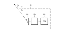
- the endoscope device 10 includes an endoscope 12, a light source device 13, a processor device 14, a monitor 15, a keyboard 16 and a foot switch 17 which are user interfaces.
- the endoscope 12 is optically connected to the light source device 13 and electrically connected to the processor device 14.
- the processor device 14 is electrically connected to a monitor 15 (display unit) that displays an image.
- the keyboard 16 and the foot switch 17, which are user interfaces, are connected to the processor device 14 and are used for various setting operations for the processor device 14.
- the user interface includes a mouse and the like in addition to the illustrated keyboard 16 or foot switch 17.
- the processor device 14 has a processor button 14a that gives various preset instructions.
- the processor button 14a may be installed on a part of an operation panel such as a touch panel connected to the processor device 14.
- the light source device 13 has a light source button 13a that gives various preset instructions.
- the endoscope 12 has an insertion portion 21 to be inserted into the subject, an operation portion 22 provided at the base end portion of the insertion portion 21, and a universal cable 23.
- the operation unit 22 has a scope button 12a in which the user of the endoscope 12 gives various preset instructions during the operation of the endoscope 12.
- the universal cable 23 captures an image of a light guide unit (not shown) that guides the illumination light emitted by the light source device 13, a control line for transmitting a control signal used for controlling the endoscope 12, and an observation target. It is a cable in which a signal line for transmitting the obtained image signal, a power line for supplying power to each part of the endoscope 12, and the like are integrated.
- a connector 25 for connecting to the light source device 13 is provided at the tip of the universal cable 23.
- the light guide portion of the endoscope 12 is a light guide bundled with an optical fiber.
- the endoscope 12 has a normal mode and a length measurement mode, and these two modes are switched by an instruction.
- the mode switching instruction can be set to any one or more of the processor button 14a, the scope button 12a, the foot switch 17, and the like. Depending on the settings, these buttons act as mode selector switches.
- the normal mode is a mode for displaying an captured image obtained by imaging an observation target illuminated by illumination light. Therefore, the measurement marker is not displayed in the normal mode.
- the length measurement mode is a mode in which the illumination light and the measurement auxiliary light are illuminated on the observation target, and a measurement marker used for measuring the size of the observation target is displayed on the captured image obtained by imaging the observation target. Is.
- the measurement auxiliary light is light used for measuring an observation target.
- the function of the still image acquisition instruction switch for instructing the acquisition of the still image of the captured image may be set to any one or more of the processor button 14a, the scope button 12a, the foot switch 17, and the like (still image). Acquisition instruction unit).
- the screen of the monitor 15 freezes and displays an alert sound (for example, "pee") to the effect that the still image is acquired.
- the still image of the captured image obtained before and after the operation timing of the scope button 12a is stored in the still image storage unit 55 (FIG. 3) in the processor device 14.
- the length measurement mode it is preferable to save the measurement information described later together with the still image of the captured image.
- the still image storage unit 55 is a storage unit such as a hard disk or a USB (Universal Serial Bus) memory.
- the processor device 14 can be connected to the network, the still image of the captured image is stored in the still image storage server (not shown) connected to the network in place of or in addition to the still image storage unit 55. You may.
- a gesture recognition unit (not shown) that recognizes the user's gesture is connected to the processor device 14, and when the gesture recognition unit recognizes a specific gesture performed by the user, a still image acquisition instruction is given. You may do it.
- the mode switching and the like may also be performed using the gesture recognition unit.
- a line-of-sight input unit (not shown) provided near the monitor 15 is connected to the processor device 14, and the line-of-sight input unit recognizes that the user's line of sight is within a predetermined area of the monitor 15 for a certain period of time or longer. If this happens, a still image acquisition instruction may be given.
- a voice recognition unit (not shown) may be connected to the processor device 14, and when the voice recognition unit recognizes a specific voice emitted by the user, a still image acquisition instruction may be given. The mode switching and the like may also be performed using the voice recognition unit.
- the tip portion 12d of the endoscope 12 has a substantially circular shape, and the objective lens 31 located closest to the subject side among the optical members constituting the imaging optical system of the endoscope 12 and the subject.
- An air supply water supply nozzle 35 for performing air supply water is provided.
- the optical axis Ax of the imaging optical system 44b extends in a direction perpendicular to the paper surface.
- the vertical first direction D1 is orthogonal to the optical axis Ax
- the horizontal second direction D2 is orthogonal to the optical axis Ax and the first direction D1.
- the objective lens 31 and the measurement auxiliary lens 33 are arranged along the first direction D1.
- the light source device 13 includes a light source unit 41 and a light source control unit 42.
- the light source unit 41 (illumination light light source unit) generates illumination light for illuminating the subject.
- the illumination light emitted from the light source unit 41 is incident on the light guide 43 and is applied to the subject through the illumination lens 32.
- the light source unit 41 includes, as a light source of illumination light, a white light source that emits white light, or a plurality of light sources including a white light source and a light source that emits light of other colors (for example, a blue light source that emits blue light). Is used.
- the light source button 13a described above is set with a function of an illumination light switch for turning on or off the illumination light.
- an illumination optical system 44a Inside the endoscope tip portion 12d, an illumination optical system 44a, an imaging optical system 44b, and a measurement auxiliary light emitting unit (measurement auxiliary light light source unit) 45 are provided.
- the illumination optical system 44a has an illumination lens 32, and the light from the light guide 43 is irradiated to the observation target through the illumination lens 32.
- the image pickup optical system 44b includes an objective lens 31 and an image pickup element 46. The reflected light from the observation target is incident on the image pickup device 46 via the objective lens 31. As a result, a reflected image to be observed is formed on the image sensor 46.
- the measurement auxiliary light emitting unit 45 emits the measurement auxiliary light used for measuring the subject.
- the image sensor 46 is a color image sensor, which captures a reflected image of a subject and outputs an image signal.
- the image sensor 46 is preferably a CCD (Charge Coupled Device) image sensor, a CMOS (Complementary Metal-Oxide Semiconductor) image sensor, or the like.
- the image pickup device 46 used in the present invention is a color image pickup sensor for obtaining RGB image signals of three colors of R (red), G (green), and B (blue).
- the image sensor 46 is controlled by the image sensor 47.
- the image signal output from the image sensor 46 is transmitted to the CDS / AGC circuit 48.
- the CDS / AGC circuit 48 performs correlated double sampling (CDS (Correlated Double Sampling)) and automatic gain control (AGC (Auto Gain Control)) on an image signal which is an analog signal.
- CDS Correlated Double Sampling
- AGC Automatic gain control
- the image signal that has passed through the CDS / AGC circuit 48 is converted into a digital image signal by the A / D converter (A / D (Analog / Digital) converter) 49.
- the A / D converted digital image signal is input to the processor device 14 via the communication I / F (Interface) 50.
- the processor device 14 includes a communication I / F 51 connected to the communication I / F 50 of the endoscope 12, a signal processing unit 52, a display control unit 53, a system control unit 54, a still image storage unit 55, and a stationary unit. It includes an image storage control unit 56.
- programs related to the signal processing unit 52, the display control unit 53, the system control unit 54, the still image storage unit 55, the still image storage control unit 56, and the like are incorporated in a memory (not shown). It has been.
- the program is operated by the system control unit 54 configured by the processor, the signal processing unit 52, the display control unit 53, the system control unit 54, the still image storage unit 55, the still image storage control unit 56, etc. And the function is realized.
- the communication I / F 51 receives the image signal transmitted from the communication I / F 50 of the endoscope 12 and transmits it to the signal processing unit 52.
- the signal processing unit 52 has a built-in memory that temporarily stores an image signal received from the communication I / F 51, and processes an image signal group that is a set of image signals stored in the memory to create an captured image. ..
- the signal processing unit 52 When the signal processing unit 52 is set to the length measurement mode, the signal processing unit 52 performs a structure enhancement process for emphasizing the structure of blood vessels and the like on the captured image, and a normal part and a lesion part of the observation target.
- the color difference enhancement process that extends the color difference may be performed.
- the display control unit 53 displays the captured image or the specific image created by the signal processing unit 52 on the monitor 15.
- the system control unit 54 controls the image pickup device 46 via the image pickup control section 47 provided on the endoscope 12.
- the image pickup control unit 47 also controls the CDS / AGC48 and the A / D49 in accordance with the control of the image pickup element 46.
- the still image storage control unit 56 controls the still image of the captured image to be stored in the still image storage unit 55.
- the measurement auxiliary light emitting unit 45 includes a light source 45a, a measurement auxiliary light generation element 45b, a prism 45c, and a measurement auxiliary lens 33.
- the light source 45a emits measurement auxiliary light.
- the light source 45a used for measuring the subject emits light of a color (specifically, visible light) that can be detected by the pixels of the image pickup element 46, and is a laser light source LD (LaserDiode) or an LED. It includes a light emitting element such as (Light Emitting Diode) and a condensing lens that collects light emitted from the light emitting element.
- the wavelength of the light emitted by the light source 45a is preferably, for example, red light of 600 nm or more and 650 nm or less. Alternatively, green light of 495 nm or more and 570 nm or less may be used.
- the measurement auxiliary light generation element 45b converts the light emitted from the light source into the measurement auxiliary light for obtaining measurement information. Specifically, the measurement auxiliary light generating element 45b uses a collimator lens, a diffractive optical element (DOE, Diffractive Optical Element), or the like in order to convert the measurement auxiliary light.
- DOE diffractive optical element
- the prism 45c is an optical member for changing the traveling direction of the measurement auxiliary light after conversion by the measurement auxiliary light generation element 45b.
- the prism 45c changes the traveling direction of the measurement auxiliary light so as to intersect the field of view of the imaging optical system including the objective lens 31 and the lens group. The details of the traveling direction of the measurement auxiliary light will be described later.
- the measurement auxiliary light Lm emitted from the prism 45c is irradiated to the subject through the measurement auxiliary lens 33.
- a specific region is formed on the subject by irradiating the subject with the measurement auxiliary light.
- the specific region is the spot SP, which is a circular region.
- the communication I / F 51 which is an image acquisition unit, acquires an captured image 57 obtained by imaging a subject illuminated by the illumination light and having a spot SP formed by the measurement auxiliary light.
- the position of the spot SP in the captured image acquired by the communication I / F 51 is specified by the position specifying unit 61 (FIG. 7). From the position of the specified spot SP, the observation distance, which is the distance between the endoscope tip portion 12d and the subject, is obtained.
- a measurement marker indicating the actual size is set according to this observation distance.
- the set measurement marker is displayed on the captured image.
- a measurement assisting slit formed in the tip portion 12d of the endoscope may be used. Further, it is preferable to apply an antireflection coating (AR (Anti-Reflection) coating) (antireflection portion) to the measurement assisting lens 33.
- AR Anti-Reflection
- the antireflection coat is provided in this way is that when the measurement auxiliary light is reflected without passing through the measurement auxiliary lens 33 and the ratio of the measurement auxiliary light applied to the subject decreases, the position specifying portion 61 (FIG. 7). ) Is because it becomes difficult to recognize the position of the spot SP formed on the subject by the measurement auxiliary light.
- the measurement auxiliary light emitting unit 45 may be any as long as it can emit the measurement auxiliary light toward the field of view of the imaging optical system.
- the light source 45a may be provided in the light source device, and the light emitted from the light source 45a may be guided to the measurement auxiliary light generation element 45b by the optical fiber.
- the measurement assistance is performed in the direction crossing the field of view of the imaging optical system. It may be configured to emit light.
- the measurement auxiliary light is in a state where the optical axis Lm of the measurement auxiliary light is within the shooting angle of view (within the region sandwiched by the two solid lines L1) of the imaging optical system. Is emitted.
- the measurement auxiliary light in the imaging range (indicated by arrows Qx, Qy, Qz) at each point.
- the position of the tip portion 12d of the endoscope is defined as the position P1.
- the observation distance is the distance between the tip portion 12d of the endoscope and the subject. Therefore, the observation distance is the distance between the position P1 and the near end Px, the near center Py, and the far end Pz, respectively.
- the observation distance is, in detail, the distance from the start point of the optical axis Ax of the imaging optical system 44b at the tip end portion 12d of the endoscope to the subject.
- the axis Dv indicates the observation distance.
- the shooting angle of view of the imaging optical system is represented in the region sandwiched between the two solid lines L1, and the measurement is performed in the central region (the region sandwiched between the two dotted lines L2) with less aberration in the shooting angle of view. ing.
- the sensitivity of the movement of the spot position to the change in the observation distance is high, so that the size of the subject can be made highly accurate. Can be measured.
- an captured image including the spot SP can be obtained.
- the position of the spot SP differs depending on the relationship between the optical axis Ax of the imaging optical system 44b and the optical axis Lm of the measurement auxiliary light and the observation distance, but if the observation distance is short, the same actual size ( For example, the number of pixels indicating 5 mm) increases, and the number of pixels decreases as the observation distance increases.
- the measurement information can be calculated from the position of the spot SP by storing in advance the information indicating the relationship between the position of the spot SP and the measurement information (number of pixels) corresponding to the actual size of the subject.
- the signal processing unit 52 of the processor device 14 recognizes the position of the spot SP, calculates the observation distance to the subject, and sets various measurement markers. Therefore, the position of the spot SP in the captured image.
- the position specifying unit 61 that specifies and calculates the observation distance
- the image processing unit 62 that sets various measurement markers based on the observation distance and creates a specific image obtained by processing the captured image using the various measurement markers. And have.
- the specific image is displayed on the monitor 15 by the display control unit 53.
- the light source unit 41 and the measurement auxiliary light emitting unit 45 continuously emit the illumination light and the measurement auxiliary light.
- the measurement auxiliary light may be turned on or dimmed to emit light.
- the captured image is an RGB image of three colors, but other color images (luminance signal Y, color difference signal Cr, Cb) may be used. Therefore, when the length measurement mode is set, the signal processing unit 52 is input with the captured image illuminated by the illumination light and the measurement auxiliary light.
- the captured image is acquired by the communication I / F51 (image acquisition unit).
- the light source unit 41 constantly emits illumination light.
- the illumination light is applied to the subject via the light guide 43.
- the light source 45a of the measurement auxiliary light emitting unit 45 is stopped, so that the measurement auxiliary light is turned off. Therefore, when the normal mode is set, the signal processing unit 52 is input with the captured image illuminated by the illumination light.
- the captured image is acquired by the communication I / F51 (image acquisition unit).
- the position specifying unit 61 specifies the position of the spot SP formed by the measurement auxiliary light on the subject.
- the position of the spot SP is specified based on the captured image in which the subject is illuminated by the illumination light and the measurement auxiliary light in the length measurement mode.
- the position specifying unit 61 identifies the position of the spot SP on the image sensor based on the image of the subject.
- the position specifying unit 61 has a distance calculating unit 63.
- the distance calculation unit 63 can obtain the observation distance from the position of the spot SP.
- the image processing unit 62 includes an image selection unit 64, a marker table 65, a measurement marker setting unit 66, a measurement marker switching reception unit 67, and a specific image creation unit 68.
- the image selection unit 64 selects an image captured in the length measurement mode, which is a target image to be processed based on the position of the spot SP, among the image captured in the normal mode and the image captured in the length measurement mode.
- the marker table 65 is a table in which information indicating the relationship between the position of the spot SP corresponding to the observation distance and the measurement information (number of pixels) corresponding to the actual size of the subject is stored in advance.
- the measurement marker setting unit 66 sets a measurement marker that represents the actual size of the observation target on the subject according to the position of the spot SP and has a scale with the end as a base point.
- the measurement marker switching reception unit 67 receives an instruction to switch and set a plurality of measurement markers.
- the specific image creation unit 68 creates a specific image in which the measurement marker set by the measurement marker setting unit 66 is superimposed on the captured image so that the position of the spot SP and the base point of the scale of the measurement marker overlap. ..
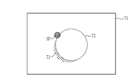
- the captured image 71 in which the subject including the polyp 72 to be observed is illuminated by the illumination light and the measurement auxiliary light is input to the signal processing unit 52.
- the captured image 71 includes the polyp 72, the spot SP, and optionally the shadow 73.
- the position specifying unit 61 specifies the position of the spot SP based on the captured image 71 input to the signal processing unit 52.
- the measurement marker setting unit 66 sets a measurement marker that represents the actual size of the observation target corresponding to the position of the spot SP and has a scale with the end as a base point. ..
- the end portion is a portion closer to the outer portion than the central portion, a start point, an end point, or the like in the shape of the measurement marker.
- the specific image creation unit 68 sets the measurement marker 75 set by the measurement marker setting unit 66 on the captured image 71, and the position of the spot SP and the base point of the scale of the measurement marker 75 are set.
- a specific image 74 superimposed so as to overlap is created.
- the measurement marker 75 is preferably superimposed so as to be displayed at the position of the spot SP for more accurate measurement. Therefore, even when displaying at a position far from the spot SP, it is preferable to display as close to the spot SP as possible.
- the measurement marker 75 is a straight line segment, and has a scale at the start point and the end point of the line segment, which is a line segment perpendicular to the straight line segment.
- the measurement marker 75 When the measurement marker 75 is a line segment or the like and has a start point and an end point, the start point and / or the end point itself may be used as a scale. In this case, for example, a line segment having a shape perpendicular to the straight line segment. There may be no scale. Further, the measurement marker 75 may have a number "10" in the vicinity of the base point of the scale. This is a scale label 75a of the measurement marker 75, and is attached so that the line segment of the measurement marker 75 can be easily recognized as having an actual size of 10 mm.
- the numbers included in the measurement markers have the same meaning.
- the numerical value of the scale label 75a can be changed by setting, and may be a measurement marker 75 that does not display the scale label 75a itself.
- Various types of measurement markers are used depending on the settings. For example, a straight line segment or a combination of straight line segments, a combination of circles or circles in shape, a combination of straight line segments and circles, and the like are used.
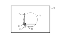
- the specific image 76 includes a measurement marker 77 whose shape is a combination of straight line segments.
- the measurement marker 77 has a shape in which straight line segments are combined in an L-shape, and the line segments extend in the upward direction and the paper surface direction with the corner of the L-shape as a base point, and each of them starts from the base point. It has a scale at the end point. Further, the measurement marker 77, like the measurement marker 75, has a number “10” which is a scale label 77a in the vicinity of the base point of the scale.
- the specific image 78 includes a measurement marker 79 whose shape is a combination of a straight line segment and a circle.
- the measurement marker 79 has a shape in which a circle and a line segment having a diameter of the circle are combined, and the line segment extends to the right of the paper surface with one of the intersections of the line segment and the circle as a base point.
- the intersection of the line segment and the circle is used as a scale.
- a scale 80 may be provided at the center of a point or circle that halves the line segment.
- the measurement marker 79 has the number “10” which is the scale label 79a in the vicinity of the base point of the scale, similarly to the measurement marker 75 or the measurement marker 77.
- the measurement markers include, for example, a measurement marker 81 (FIG. 12A) including a scale label 81a in which a line segment extends from the base point to the left of the paper surface, and the paper surface from the base point.
- a measurement marker 82 (FIG. 12 (B)) containing a scale label 82a with a downward line segment, or a measurement marker 83 (FIG. 12) containing a scale label 83a with a line segment extending diagonally to the upper right of the paper surface from the base point. It can take various shapes such as (C)).
- a graduated cross shape in which a scale Mx is attached to at least one of a cross-shaped vertical line and a horizontal line may be used.
- a distorted cross shape in which at least one of a vertical line and a horizontal line is tilted may be formed.
- it may be a circle or a cross shape in which a cross shape and a circle are combined.
- the scale can be from each end of the cross to the intersection of the cross.
- a measurement point cloud type may be obtained by combining a plurality of measurement point EPs corresponding to the actual size from the spot SP. In this case, the distance from the spot SP to the measurement point EP can be used as a scale.
- the number of measurement markers may be one or more, and the color of the measurement markers may be changed according to the actual size.
- the size of the measurement marker may be a measurement marker having a size suitable for the observation target, or a measurement marker having a size smaller or larger than the observation mode, and the actual size of the measurement marker is the observation target. Or any value (for example, 2 mm, 3 mm, 10 mm, etc.) may be set according to the purpose of observation.
- the scale of the measurement marker may be uneven.
- the measurement marker setting unit 66 sets a measurement marker having a strain in consideration of the three-dimensional shape of the observation target. Consideration of the three-dimensional shape is performed by estimating the height of the three-dimensional shape from the distance to the observation target calculated by the distance calculation unit 63, or by estimating the size or shape of the three-dimensional shape by image analysis of the captured image. In the image analysis, a machine learning technique using a trained model in which the captured image is learned may be used.
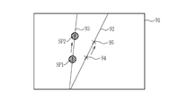
- the spot SP2 is formed at the apex 72a of the polyp 72 by the measurement auxiliary light Lm.
- the distance from the spot SP2 to the observation target is the distance D5 between the position P1 of the endoscope tip 12d and the position P2 of the spot SP2.
- the spot SP1 is formed at the end portion 72b of the polyp 72 by the measurement auxiliary light Lm.
- the distance from the spot SP1 to the observation target is the distance D6 between the position P1 of the endoscope tip 12d and the position P3 of the spot SP1. Therefore, the height of the polyp 72 is the distance D3, which is the difference between the distance D6 and the distance D5.
- the measurement marker setting unit 66 calculates the distance D3 by storing the distance D6 and the distance D3, for example, and sets it as the height of the observation target.
- the three-dimensional shape is grasped by using the information on the size and / or shape of the observation target estimated by image analysis of the observation image.
- the measurement marker setting unit 66 sets a measurement marker having a strain in consideration of the three-dimensional shape of the observation target grasped in this way.
- the measurement marker setting unit 66 sets the measurement marker 85 having a strain in consideration of the three-dimensional shape of the polyp 72 based on the height, size, shape information, and the like of the polyp 72. ..
- the measurement marker 85 has a scale 85a, a scale 85b, and a scale 85c.
- the scale 85a is at the start point of the measurement marker 85
- the scale 85c is at the end point of the measurement marker 85.
- the scale 85b is on the end point side from the center of the measurement marker 85.
- the number "10" of the scale label 85d and the scale label 85e indicates that the measured size from the scale 85a to the scale 85b is 10 mm, and the measured size from the scale 85b to the scale 85c is 10 mm, respectively. ..
- the distance from the scale 85a to the scale 85b and the distance from the scale 85b to the scale 85c are not the same length on the observation image, but since the actual polyp 72 is spherical, it is for measurement.
- the scale of the marker 85 represents the actual size.
- the measurement marker setting unit 66 sets the measurement marker 85, and the specific image creation unit 68 superimposes the measurement marker 85 on the captured image to create the specific image 84.
- the measurement marker setting unit 66 sets the measurement marker that represents the actual size according to the position of the spot SP and has a scale with the end as the base point
- the specific image creation unit 68 sets the measurement marker.
- a specific image is created by superimposing the measurement marker set by the measurement marker setting unit 66 on the captured image so that the position of the spot SP and the base point of the scale of the measurement marker overlap.
- the observation target it is natural for the observation target to be measured by the user to be positioned at the center of the image captured by the endoscope for detailed observation in order to observe in more detail. Therefore, by creating a specific image in which the measurement markers are superimposed as described above, the positions of the measurement markers can be arranged more appropriately. Therefore, for example, it is possible to display a more accurate scale on the observation target than when the measurement marker is arranged on the peripheral portion of the captured image.
- the observation target that the user wants to measure may have a three-dimensional shape. Therefore, by creating a specific image in which the measurement markers are superimposed as described above, when the spot SP is formed at the apex portion of the three-dimensional shape, the measured value by the measurement marker is shorter than the distance of the actual observation target. Or, it is possible to display a measurement marker closer to the actual distance by reducing the error measured smaller than the size of the actual observation target. Therefore, a more accurate scale can be displayed for the observation target. As described above, it is possible to prevent the size of the observation target, for example, the polyp from being underestimated, and to make a more appropriate diagnosis.
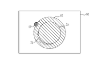
- the specific image creation unit 68 creates a superposed specific image in the captured image so that the center of the measurement marker is located on the center side of the spot SP position. In many cases, it is natural to position the observation target to be measured at the center of the image captured by the endoscope for detailed observation in order to observe it in more detail. Therefore, by creating a specific image in which the measurement marker is arranged at the center of the spot SP, a more appropriate measurement marker can be arranged.
- the center of the measurement marker is located in the region 87, which is the region on the center side of the specific image 86 from the position of the spot SP, so that the position of the measurement marker is set. , Can be placed more appropriately.
- Region 87 is a region shown by diagonal lines in FIG. Therefore, for example, it is possible to display a more accurate scale on the observation target than when the measurement marker is arranged on the peripheral portion of the captured image.
- the peripheral portion of the captured image can be a region other than the region 87 in the specific image 86.
- the measurement auxiliary light emitting unit 45 emits the measurement auxiliary light so that the locus formed by the measurement auxiliary light on the subject is different from the locus formed by the optical axis of the image pickup device (optical axis of the image pickup optical system). Is preferable. Further, different trajectories mean that the trajectories do not match. As a result, the observation target is formed closer to the center of the captured image, and the spot SP is formed outside the vicinity of the optical axis of the imaging optical system. Therefore, the observation target can be placed in the center, and the observation target can be observed. It will be easier.
- the optical axis of the imaging optical system is When it is at the observation point 94, the spot SP1 by the measurement auxiliary light moves to the left side of the observation point 94 in the captured image 91, and then moves to the observation point, and the optical axis of the imaging optical system is the observation point 95.
- the spot SP2 by the measurement auxiliary light adjusts the measurement auxiliary light so that it is on the left side of the observation point 95 in the captured image 91.
- the locus 93 formed by the measurement auxiliary light is preferably outside the locus formed by the optical axis of the imaging optical system on the subject, and may be on the left side or the right side, or on the upper side or the lower side. Therefore, since the measurement marker is arranged closer to the center of the captured image than the spot SP, it is possible to display a more accurate scale on the observation target.
- the measurement marker switching reception unit 67 receives an instruction to switch the measurement marker to be set.
- the measurement marker setting unit 66 switches and sets a plurality of different measurement markers according to the instructions of the measurement marker switching reception unit 67.
- various shapes can be set. Therefore, for example, by assigning an instruction for switching the setting of the measurement marker in advance to any one or more of the processor button 14a, the scope button 12a, the foot switch 17, etc., the user can perform the most suitable measurement during observation. A specific image can be created by switching to the marker.
- the measurement marker setting unit may switch to a measurement marker having a scale having a base point at the end portion and set a measurement marker having a scale having a center portion as a base point. Even when setting a measurement marker having a scale with the central portion as the base point, it is possible to create a specific image in which the measurement marker is superimposed on the captured image so that the spot SP and the base point of the scale of the measurement marker overlap. preferable.
- the captured image is used for measurement so that the spot SP and the end of the measurement marker 103 overlap.
- the marker 103 is superimposed. Since the scale label 103a of the scale of the measurement marker 103 is displayed as "10", the length from the start point to the end point is 10 mm in the measured size.
- the foot switch 17 which is the measurement marker switching reception unit 67 is operated.
- the foot switch 17 has a left switch 17a and a right switch 17b (FIG. 1).
- the left switch 17a is a changeover switch that circulates and switches and displays a plurality of different measurement markers one after another.
- the plurality of measurement markers include, in addition to a measurement marker having a scale having a base point at the end, a measurement marker having a scale having a center point as a base point.
- the right switch 17b is a confirmation switch, and is operated by stepping on the right switch 17b with a foot when a desired measurement marker is displayed.
- the measurement marker 103 is switched to the measurement marker 105.
- the position of the spot SP is not changed, and the measurement marker is switched from the measurement marker 103 to the measurement marker 105. Since the position of the spot SP is not changed, the user shifts the imaging optical system to the right so that the polyp 102 can be measured.
- the measurement marker is a cross-shaped marker, and line segments extend vertically and horizontally from the center, and the scale label 105a is displayed as "5". Therefore, each line segment represents the actually measured size of 5 mm. Thereby, the size or length of the polyp 102 can be measured and grasped.
- the specific image 101 is changed to the specific image 106, it is the case where the measurement marker 103 is switched to the measurement marker 107.
- the position of the spot SP is changed to move it to the center of the captured image.
- the observation target can be observed, photographed or measured at the center of the captured image.
- the scale label 107a is displayed as "5" by the specific image 106, it was found that the polyp 102 has a shorter length of a three-dimensional shape such as connecting two spheres, which is about 10 mm.
- the measurement marker switching reception unit 67 can switch from the specific image 101 to the specific image 104 and also from the specific image 104 to the specific image 101.
- the specific image 101 can be switched to the specific image 106, and the specific image 106 can be switched to the specific image 101.
- the measurement markers may be switched to measurement markers having the same shape but different scales. As a result, the measurement marker that the user considers to be more appropriate can be easily set as desired.
- the measurement auxiliary light emitting unit 45 does not emit the measurement auxiliary light when the illumination light is turned off by the illumination light switch for turning on or off the illumination light for illuminating the subject. ..
- the light source button 13a (FIG. 1) of the light source device 13 has a function of an illumination light switch.
- the measurement auxiliary light emitting unit 45 prevents the measurement auxiliary light from being emitted. Since the measurement auxiliary light is a laser light in the present embodiment, it is preferable not to turn it on when the endoscope is outside the body from the viewpoint of safety.
- the illumination light switch is provided with an interlock function of the measurement auxiliary light. Therefore, when the illumination light is turned off by the illumination light switch, even if an instruction is given to turn on the measurement auxiliary light, it is possible to prevent unintended emission of the measurement auxiliary light. Since the measurement auxiliary light is turned on when the length measurement mode is switched to, any of the processor button 14a, the scope button 12a, the foot switch 17, etc., for which the mode switching instruction is set, as described above. Even if one or more of them are operated unintentionally, for example, when the endoscope is outside the body and the illumination light is turned off by the illumination light switch, the emission of the measurement auxiliary light is prevented. be able to.
- the subject is observed in the normal mode (step ST110). For example, when an observation target that needs to be observed and measured is found in the subject, the mode shifts to the length measurement mode (YES in step ST120). If the mode does not shift to the length measurement mode (NO in step ST120), the observation in the normal mode is continued.
- the measurement auxiliary light emitting unit 45 emits the measurement auxiliary light (step ST140), and the image sensor acquires an captured image of the subject (step ST150). Based on the captured image, the position specifying unit 61 specifies the position of the spot ST (step ST160). In some cases, the distance calculation unit 63 calculates the distance of the endoscope tip portion 12d from the subject (step ST170) and sends it to the measurement marker setting unit 66 or the like.
- the measurement marker setting unit 66 sets the measurement marker using the obtained information (step ST180).
- the measurement marker setting unit 66 sets a measurement marker that represents the actual size according to the position of the spot SP specified by the position specifying unit 61 and has a scale with the end as a base point.
- the process returns to before setting the measurement marker. If the measurement marker is not switched (YES in step ST190), the process proceeds to create a specific image.
- a specific image is created by superimposing the measurement marker on the captured image so that the position of the spot SP and the base point of the scale of the measurement marker overlap (step ST200). After creating the specific image, the specific image may be displayed on the monitor 15 (FIG. 1) or the like (step ST210).
- the hardware structure of the processing unit (processing unit) that executes various processes is as follows.
- processor the circuit configuration is changed after manufacturing the CPU (Central Processing Unit), FPGA (Field Programmable Gate Array), etc., which are general-purpose processors that execute software (programs) and function as various processing units. It includes a programmable logic device (PLD), which is a possible processor, a dedicated electric circuit, which is a processor having a circuit configuration specially designed for executing various processes, and the like.
- PLD programmable logic device
- One processing unit may be composed of one of these various processors, or may be composed of a combination of two or more processors of the same type or different types (for example, a plurality of FPGAs or a combination of a CPU and an FPGA). May be done. Further, a plurality of processing units may be configured by one processor. As an example of configuring a plurality of processing units with one processor, first, as represented by a computer such as a client or a server, one processor is configured by a combination of one or more CPUs and software. There is a form in which this processor functions as a plurality of processing units.
- SoC System On Chip
- a processor that realizes the functions of the entire system including a plurality of processing units with one IC (Integrated Circuit) chip is used.
- the various processing units are configured by using one or more of the above-mentioned various processors as a hardware-like structure.
- an electric circuit in the form of a combination of circuit elements such as semiconductor elements is, more specifically, an electric circuit in the form of a combination of circuit elements such as semiconductor elements.
- Another aspect of the present invention is an endoscope device including a measurement auxiliary light source unit that emits measurement auxiliary light used for measuring a subject and an image pickup element that images the subject, and a processor assists measurement on the subject.
- the position of a specific region formed by light was specified, the actual size was represented according to the position of the specified specific region, and a measurement marker having a scale with the end as a base point was set, and an image was taken by an image sensor.
- This is an endoscope device that creates a specific image in which a measurement marker is superimposed so that the position of a specific area and the base point of the scale of the measurement marker overlap with the captured image of the subject.
- the present invention is not limited to the above-described embodiment, and various configurations can be adopted as long as the gist of the present invention is not deviated. Further, the present invention extends to a storage medium for storing a program in addition to the program.
Abstract
観察対象に対してより正確なスケールを表示する内視鏡装置(10)及びその作動方法並びに内視鏡装置用プログラムを提供する。 内視鏡装置(10)は、プロセッサを備え、計測補助光による特定領域が形成された被写体を撮像して得られる撮像画像において、プロセッサが特定領域の位置を特定し、特定領域の位置に応じて、被写体の実寸サイズを表し、かつ、端部を基点とする目盛りを有する計測用マーカを設定し、特定領域の位置と計測用マーカの目盛りの基点とが重なるように、撮像画像に計測用マーカを重畳した特定画像を作成する。
Description
本発明は、被写体の大きさを測定する内視鏡装置及びその作動方法並びに内視鏡装置用プログラムに関する。
内視鏡装置では、被写体までの距離の計測、又は被写体の長さ若しくは大きさの算出が行われている。例えば、特許文献1では、被写体に対して計測補助光を照射し、被写体上にスポットを形成する。被写体を撮像して得られる撮像画像から、スポットの位置を特定する。そして、スポットの位置に応じて、被写体に含まれる観察対象における実サイズを示す指標図形を設定し、設定した指標図形からなる計測用マーカを撮像画像上に表示することが行われている。計測用マーカは、例えば、上下左右に広がるスケールを有するので、表示される計測用マーカを観察対象に合わせることにより観察対象の大きさを計測することができる。このようにして、撮像画像上に表示された計測用マーカを用いることで、観察対象の大きさを計測することが可能となる。
内視鏡装置より撮像する被写体は、表面が凹凸形状等の立体形状を有する場合がある。計測補助光によるスポットが立体形状上に形成された場合、観察対象の実際の大きさと異なる大きさの計測用マーカが表示され、誤差が生じる場合があった。これは、スポットが形成された立体形状上の位置と、凹凸形状等の立体形状部分が無いとした場合のスポット位置、すなわち、立体形状の根元におけるスポット位置とで、スポット光軸の奥行き方向距離の差異が生じるためである。特に、観察対象を詳細に観察又は診断をするために、観察対象を近くで、かつ、撮像画像の中心に位置させて観察する場合は、スポットが立体形状上に形成される場合が多くなる。したがって、観察対象を詳細に観察する場合は特に、スポットの位置によって表示したスケールにおいて誤差が生じる場合があった。
これに対し、被写体又は観察対象の立体形状を予め定義しておき、予測される誤差をオフセットしたスケールを表示する方法が考えられる。しかしながら、実際の凹凸形状は様々であるし、オフセットを行う定義も複雑になるおそれがある。
本発明は、上記実情に鑑み、観察対象に対してより正確なスケールを表示する内視鏡装置及びその作動方法並びに内視鏡装置用プログラムを提供することを目的とする。
本発明は、内視鏡装置であって、被写体の計測に用いる計測補助光を発する計測補助光光源部と、被写体を撮像する撮像素子と、プロセッサとを備える。プロセッサは、被写体上において計測補助光によって形成される特定領域の位置を特定し、特定領域の位置に応じて被写体の実寸サイズを表し、かつ、端部を基点とする目盛りを有する計測用マーカを設定し、撮像素子により撮像した被写体の撮像画像に、特定領域の位置と計測用マーカの目盛りの基点とが重なるように、計測用マーカを重畳した特定画像を作成する。
計測用マーカは、形状が直線の線分又は直線の線分の組み合わせであることが好ましい。
計測用マーカは、形状が円又は円の組み合わせであることが好ましい。
計測用マーカは、目盛りが不均等であることが好ましい。
プロセッサは、撮像画像において、計測用マーカの中心が特定領域の位置より中央側に位置するように重畳した特定画像を作成することが好ましい。
計測補助光光源部は、被写体上において、計測補助光が形成する軌跡が、撮像素子の光軸が形成する軌跡と異なるように計測補助光を発することが好ましい。
プロセッサは、設定する計測用マーカを切替える指示を受け付け、指示に従い、互いに異なる複数の計測用マーカを切替えて設定することが好ましい。
プロセッサは、端部を基点とする目盛りを有する計測用マーカと切替えて、中央部を基点とする目盛りを有する計測用マーカを設定することが好ましい。
被写体を照明するための照明光を発する照明光光源部と、照明光の点灯又は消灯を行う照明光スイッチとを備え、計測補助光光源部は、照明光スイッチにより照明光の消灯が行われている場合、計測補助光を発しないことが好ましい。
また、本発明は内視鏡装置の作動方法であって、被写体の計測に用いる計測補助光を発するステップと、被写体を撮像するステップと、被写体上において計測補助光によって形成される特定領域の位置を特定するステップと、特定領域の位置に応じて被写体の実寸サイズを表し、かつ、端部を基点とする目盛りを有する計測用マーカを設定するステップと、撮像素子により撮像した被写体の撮像画像に、特定領域の位置と計測用マーカの目盛りの基点とが重なるように計測用マーカを重畳した特定画像を作成するステップとを有する。
また、本発明は内視鏡装置用プログラムであって、被写体の計測に用いる計測補助光を発する計測補助光光源部と、被写体を撮像する撮像素子とを備える内視鏡装置に用いるプログラムであり、被写体上において計測補助光によって形成される特定領域の位置を特定する機能と、特定領域の位置に応じて被写体の実寸サイズを表し、かつ、端部を基点とする目盛りを有する計測用マーカを設定する機能と、撮像素子により撮像した被写体の撮像画像に、特定領域の位置と計測用マーカの目盛りの基点とが重なるように計測用マーカを重畳した特定画像を作成する機能とをコンピュータに実行させる。
本発明によれば、観察対象に対してより正確なスケールを表示することができる。
図1に示すように、内視鏡装置10は、内視鏡12と、光源装置13、プロセッサ装置14と、モニタ15と、ユーザーインターフェースであるキーボード16及びフットスイッチ17とを有する。内視鏡12は光源装置13と光学的に接続され、かつ、プロセッサ装置14と電気的に接続される。プロセッサ装置14は、画像を表示するモニタ15(表示部)に電気的に接続されている。ユーザーインターフェースであるキーボード16及びフットスイッチ17は、プロセッサ装置14に接続されており、プロセッサ装置14に対する各種設定操作等に用いられる。なお、ユーザーインターフェースは図示したキーボード16又はフットスイッチ17の他、マウス等が含まれる。
プロセッサ装置14は、予め設定した各種の指示を行うプロセッサボタン14aを有する。プロセッサボタン14aは、プロセッサ装置14に接続されたタッチパネルなどのオペレーションパネルの一部に設置してもよい。また、光源装置13は、予め設定した各種の指示を行う光源ボタン13aを有する。
内視鏡12は、被検体内に挿入する挿入部21と、挿入部21の基端部分に設けられた操作部22と、ユニバーサルケーブル23とを有する。操作部22は、内視鏡12のユーザーが、内視鏡12の操作中に予め設定した各種の指示を行うスコープボタン12aを有する。ユニバーサルケーブル23は、光源装置13が発する照明光を導光する導光部(図示しない)や、内視鏡12の制御に使用する制御信号を伝送するための制御線、観察対象を撮像して得られた画像信号を送信する信号線、内視鏡12の各部に電力を供給する電力線等が一体になったケーブルである。ユニバーサルケーブル23の先端には光源装置13に接続するコネクタ25が設けられている。また、内視鏡12の導光部は、光ファイバをバンドルしたライトガイドである。
内視鏡12は、通常モードと、測長モードとを備えており、これら2つのモードは指示によって切替える。モード切替の指示は、プロセッサボタン14a、スコープボタン12a、又はフットスイッチ17等のいずれか一つ又は複数に設定することができる。設定により、これらのボタンは、モード切替スイッチとして機能する。
通常モードは、照明光によって照明された観察対象を撮像して得られる撮像画像を表示するモードである。したがって、通常モードでは計測用マーカの表示を行わない。測長モードは、照明光及び計測補助光を観察対象に照明し、且つ、観察対象の撮像により得られる撮像画像上に、観察対象の大きさなどの測定に用いられる計測用マーカを表示するモードである。計測補助光は、観察対象の計測に用いられる光である。
なお、プロセッサボタン14a、スコープボタン12a、又はフットスイッチ17等のいずれか一つ又は複数に、撮像画像の静止画の取得を指示する静止画取得指示スイッチの機能を設定してもよい(静止画取得指示部)。ユーザーが静止画取得指示スイッチにより静止画の取得を指示することにより、モニタ15の画面がフリーズ表示し、合わせて、静止画取得を行う旨のアラート音(例えば「ピー」)を発する。そして、例えば、スコープボタン12aの操作タイミング前後に得られる撮像画像の静止画が、プロセッサ装置14内の静止画保存部55(図3)に保存される。また、測長モードに設定されている場合には、撮像画像の静止画と合わせて、後述する計測情報も保存することが好ましい。なお、静止画保存部55はハードディスクやUSB(Universal Serial Bus)メモリなどの記憶部である。プロセッサ装置14がネットワークに接続可能である場合には、静止画保存部55に代えて又は加えて、ネットワークに接続された静止画保存サーバ(図示しない)に撮像画像の静止画を保存するようにしてもよい。
また、プロセッサ装置14に、ユーザーのジェスチャーを認識するジェスチャー認識部(図示しない)を接続し、ジェスチャー認識部が、ユーザーによって行われた特定のジェスチャーを認識した場合に、静止画取得指示を行うようにしてもよい。なお、モード切替等についても、ジェスチャー認識部を用いて行うようにしてもよい。
また、モニタ15の近くに設けた視線入力部(図示しない)をプロセッサ装置14に接続し、視線入力部が、モニタ15のうち所定領域内にユーザーの視線が一定時間以上入っていることを認識した場合に、静止画取得指示を行うようにしてもよい。また、プロセッサ装置14に音声認識部(図示しない)を接続し、音声認識部が、ユーザーが発した特定の音声を認識した場合に、静止画取得指示を行うようにしてもよい。モード切替等についても、音声認識部を用いて行うようにしてもよい。
図2に示すように、内視鏡12の先端部12dは略円形となっており、内視鏡12の撮像光学系を構成する光学部材のうち最も被写体側に位置する対物レンズ31と、被写体に対して照明光を照射するための照明レンズ32と、後述する計測補助光を被写体に照明するための計測補助用レンズ33と、処置具を被写体に向けて突出させるための開口34と、送気送水を行うための送気送水ノズル35とが設けられている。
撮像光学系44b(図3)の光軸Axは、紙面に対して垂直な方向に延びている。縦の第1方向D1は、光軸Axに対して直交しており、横の第2方向D2は、光軸Ax及び第1方向D1に対して直交する。対物レンズ31と計測補助用レンズ33とは、第1方向D1に沿って配列されている。
図3に示すように、光源装置13は、光源部41と、光源制御部42とを備えている。光源部41(照明光光源部)は、被写体を照明するための照明光を発生する。光源部41から出射された照明光は、ライトガイド43に入射され、照明レンズ32を通って被写体に照射される。光源部41としては、照明光の光源として、白色光を出射する白色光源、又は、白色光源とその他の色の光を出射する光源(例えば青色光を出射する青色光源)を含む複数の光源等が用いられる。なお、本実施形態では、上述した光源ボタン13aに、照明光の点灯又は消灯を行う照明光スイッチの機能を設定する。
内視鏡先端部12dの内部には、照明光学系44a、撮像光学系44b、及び計測補助光出射部(計測補助光光源部)45が設けられている。照明光学系44aは照明レンズ32を有しており、この照明レンズ32を介して、ライトガイド43からの光が観察対象に照射される。撮像光学系44bは、対物レンズ31及び撮像素子46を有している。観察対象からの反射光は、対物レンズ31を介して、撮像素子46に入射する。これにより、撮像素子46に観察対象の反射像が結像される。計測補助光出射部45は、被写体の計測に用いる計測補助光を発する。
撮像素子46はカラーの撮像センサであり、被写体の反射像を撮像して画像信号を出力する。この撮像素子46は、CCD(Charge Coupled Device)撮像センサやCMOS(Complementary Metal-Oxide Semiconductor)撮像センサ等であることが好ましい。本発明で用いられる撮像素子46は、R(赤)、G(緑)B(青)の3色のRGB画像信号を得るためのカラーの撮像センサである。撮像素子46は、撮像制御部47によって制御される。
撮像素子46から出力される画像信号は、CDS/AGC回路48に送信される。CDS/AGC回路48は、アナログ信号である画像信号に相関二重サンプリング(CDS(Correlated Double Sampling))や自動利得制御(AGC(Auto Gain Control))を行う。CDS/AGC回路48を経た画像信号は、A/D変換器(A/D(Analog /Digital)コンバータ)49により、デジタル画像信号に変換される。A/D変換されたデジタル画像信号は、通信I/F(Interface)50を介して、プロセッサ装置14に入力される。
プロセッサ装置14は、内視鏡12の通信I/F50と接続される通信I/F51と、信号処理部52と、表示制御部53と、システム制御部54と、静止画保存部55と、静止画保存制御部56とを備えている。プロセッサ装置14には、信号処理部52と、表示制御部53と、システム制御部54と、静止画保存部55と、静止画保存制御部56等とに関するプログラムがメモリ(図示せず)に組み込まれている。プロセッサによって構成されるシステム制御部54によってそのプログラムが動作することで、信号処理部52と、表示制御部53と、システム制御部54と、静止画保存部55と、静止画保存制御部56等との機能が実現する。
通信I/F51は、内視鏡12の通信I/F50から伝送されてきた画像信号を受信して信号処理部52に伝達する。信号処理部52は、通信I/F51から受けた画像信号を一時記憶するメモリを内蔵しており、メモリに記憶された画像信号の集合である画像信号群を処理して、撮像画像を作成する。なお、信号処理部52では、測長モードに設定されている場合には、撮像画像に対して、血管などの構造を強調する構造強調処理や、観察対象のうち正常部と病変部などとの色差を拡張した色差強調処理を施すようにしてもよい。
表示制御部53は、信号処理部52によって作成された撮像画像又は特定画像をモニタ15に表示する。システム制御部54は、内視鏡12に設けられた撮像制御部47を介して、撮像素子46の制御を行う。撮像制御部47は、撮像素子46の制御に合わせて、CDS/AGC48及びA/D49の制御も行う。静止画保存制御部56は、静止画保存部55に保存する撮像画像の静止画に関する制御を行う。
図4に示すように、計測補助光出射部45は、光源45aと、計測補助光生成素子45bと、プリズム45cと、計測補助用レンズ33とを備える。光源45aは、計測補助光を発する。計測補助光は、被写体の計測に用いる光源45aは、撮像素子46の画素によって検出可能な色の光(具体的には可視光)を出射するものであり、レーザー光源LD(Laser Diode)又はLED(Light Emitting Diode)等の発光素子と、この発光素子から出射される光を集光する集光レンズとを含む。
光源45aが出射する光の波長は、例えば、600nm以上650nm以下の赤色光であることが好ましい。もしくは、495nm以上570nm以下の緑色光を用いてもよい。計測補助光生成素子45bは、光源から出射した光を、計測情報を得るための計測補助光に変換する。計測補助光に変換するために、計測補助光生成素子45bは、具体的には、コリメータレンズ、又は回折光学素子(DOE、Diffractive Optical Element)等を用いる。
プリズム45cは、計測補助光生成素子45bで変換後の計測補助光の進行方向を変えるための光学部材である。プリズム45cは、対物レンズ31及びレンズ群を含む撮像光学系の視野と交差するように、計測補助光の進行方向を変更する。計測補助光の進行方向の詳細については、後述する。プリズム45cから出射した計測補助光Lmは、計測補助用レンズ33を通って、被写体へと照射される。
図5に示すように、計測補助光が被写体に照射されることにより、被写体上において、特定領域が形成される。本実施形態において、特定領域はスポットSPであり、円状の領域となる。画像取得部である通信I/F51は、照明光によって照明され、かつ、計測補助光によるスポットSPが形成された被写体を撮像して得られる撮像画像57を取得する。通信I/F51が取得した撮像画像におけるスポットSPの位置が、位置特定部61(図7)によって特定される。特定されたスポットSPの位置から、内視鏡先端部12dと被写体との距離である観察距離が求められる。この観察距離に応じて、実寸サイズを表す計測用マーカを設定する。設定された計測用マーカは、撮像画像上に表示される。
なお、計測補助用レンズ33に代えて、内視鏡先端部12dに形成される計測補助用スリットとしてもよい。また、計測補助用レンズ33には、反射防止コート(AR(Anti-Reflection)コート)(反射防止部)を施すことが好ましい。このように反射防止コートを設けるのは、計測補助光が計測補助用レンズ33を透過せずに反射して、被写体に照射される計測補助光の割合が低下すると、位置特定部61(図7)が、計測補助光により被写体上に形成されるスポットSPの位置を認識し難くなるためである。
計測補助光出射部45は、計測補助光を撮像光学系の視野に向けて出射できるものであればよい。例えば、光源45aが光源装置に設けられ、光源45aから出射された光が光ファイバによって計測補助光生成素子45bにまで導光されるものであってもよい。また、プリズム45cを用いずに、光源45a及び計測補助光生成素子45bの向きを撮像光学系44bの光軸Axに対して斜めに設置することで、撮像光学系の視野を横切る方向に計測補助光を出射させる構成としてもよい。
計測補助光の進行方向については、図6に示すように、計測補助光の光軸Lmが撮像光学系の撮影画角(2つの実線L1で挟まれる領域内)に入る状態で、計測補助光を出射する。観察距離の範囲Rxにおいて観察可能であるとすると、範囲Rxの近端Px、中央付近Py、及び遠端Pzでは、各点での撮像範囲(矢印Qx、Qy、Qzで示す)における計測補助光によって被写体上に形成されるスポットSPの位置(各矢印Qx、Qy、Qzが光軸Lmと交わる点)が異なることが分かる。内視鏡先端部12dの位置を位置P1とする。観察距離は、内視鏡先端部12dと被写体との距離である。したがって、観察距離は、それぞれ、位置P1と、近端Px、中央付近Py、及び遠端Pzとの間の距離である。観察距離は、詳細には、内視鏡先端部12dにおける撮像光学系44bの光軸Axの始点から被写体までの距離となる。軸Dvは観察距離を示す。なお、撮像光学系の撮影画角は2つの実線L1で挟まれる領域内で表され、この撮影画角のうち収差の少ない中央領域(2つの点線L2で挟まれる領域)で計測を行うようにしている。
以上のように、撮像光学系の撮影画角に入る状態で、計測補助光を出射することによって、観察距離の変化に対するスポット位置の移動の感度が高いことから、被写体の大きさを高精度に計測することができる。計測補助光が照明された被写体を撮像素子46で撮像することによって、スポットSPを含む撮像画像が得られる。撮像画像では、スポットSPの位置は、撮像光学系44bの光軸Axと計測補助光の光軸Lmとの関係、及び観察距離に応じて異なるが、観察距離が近ければ、同一の実寸サイズ(例えば5mm)を示すピクセル数が多くなり、観察距離が遠ければピクセル数が少なくなる。
したがって、スポットSPの位置と被写体の実寸サイズに対応する計測情報(ピクセル数)との関係を示す情報を予め記憶しておくことで、スポットSPの位置から計測情報を算出することができる。
図7に示すように、プロセッサ装置14の信号処理部52は、スポットSPの位置認識及び被写体との観察距離の算出、並びに各種計測用マーカの設定を行うために、撮像画像におけるスポットSPの位置を特定し、観察距離を算出する位置特定部61と、観察距離に基づいて、各種計測用マーカを設定し、各種計測用マーカを用いて撮像画像を加工した特定画像を作成する画像加工部62とを備えている。特定画像は、表示制御部53によって、モニタ15に表示される。
測長モードに設定されている場合には、光源部41及び計測補助光出射部45は、照明光と計測補助光とを連続的に発光する。場合によっては、計測補助光は、点灯または減光して発光してもよい。なお、撮像画像は3色のRGB画像とするが、その他のカラー画像(輝度信号Y、色差信号Cr、Cb)であってもよい。したがって、信号処理部52には、測長モードに設定されている場合には、照明光および計測補助光により照明された撮像画像が入力される。撮像画像は、通信I/F51(画像取得部)で取得される。
なお、通常モードに設定されている場合には、光源部41は、照明光を常時発する。照明光は、ライトガイド43を介して被写体に照射される。通常モードの場合には、計測補助光出射部45の光源45aは停止するので、計測補助光は消灯する。したがって、信号処理部52には、通常モードに設定されている場合には、照明光により照明された撮像画像が入力される。撮像画像は、通信I/F51(画像取得部)で取得される。
位置特定部61は、被写体上において計測補助光によって形成されるスポットSPの位置を特定する。スポットSPの位置の特定は、測長モードにて照明光および計測補助光により被写体を照明した撮像画像に基づいて行う。撮像画像は、計測補助光によりスポットSPが形成された被写体の画像を撮像光学系及び撮像素子を介して取得される。したがって、位置特定部61は、被写体の画像に基づいて撮像素子上のスポットSPの位置を特定する。また、位置特定部61は、距離算出部63を有する。距離算出部63は、スポットSPの位置から観察距離を求めることができる。
画像加工部62は、画像選択部64、マーカ用テーブル65、計測用マーカ設定部66、計測用マーカ切替受付部67、及び特定画像作成部68を有する。画像選択部64は、通常モードによる撮像画像と、測長モードによる撮像画像のうち、スポットSPの位置に基づく加工を行う対象画像である、測長モードによる撮像画像を選択する。マーカ用テーブル65は、観察距離に対応するスポットSPの位置と被写体の実寸サイズに対応する計測情報(ピクセル数)との関係を示す情報を予め記憶したテーブルである。計測用マーカ設定部66は、スポットSPの位置に応じて被写体上の観察対象の実寸サイズを表し、かつ、端部を基点とする目盛りを有する計測用マーカを設定する。計測用マーカ切替受付部67は、複数の計測用マーカを切替えて設定する指示を受け付ける。特定画像作成部68は、撮像画像に、計測用マーカ設定部66により設定された計測用マーカを、スポットSPの位置と計測用マーカの目盛りの基点とが重なるように重畳した特定画像を作成する。
計測用マーカ設定部66及び特定画像作成部68の機能について以下に具体的に説明する。図8に示すように、測長モードにおいて、照明光および計測補助光により観察対象であるポリープ72を含む被写体が照明された撮像画像71が、信号処理部52に入力される。例えば、ポリープ72が球状の立体形状を有するため、撮像画像71は、ポリープ72と、スポットSPと、場合により影73とを含む。
信号処理部52に入力された撮像画像71に基づき、位置特定部61は、スポットSPの位置を特定する。計測用マーカ設定部66は、マーカ用テーブル65を参照して、スポットSPの位置に対応した、観察対象の実寸サイズを表し、かつ、端部を基点とする目盛りを有する計測用マーカを設定する。端部とは、計測用マーカの形状において、中央部分よりも外側部分に近い部分又は始点若しくは終点等である。
図9に示すように、特定画像作成部68は、撮像画像71に、計測用マーカ設定部66により設定された計測用マーカ75を、スポットSPの位置と計測用マーカ75の目盛りの基点とが重なるように重畳した特定画像74を作成する。計測用マーカ75は、より正確な計測のために、スポットSPの位置に表示するように重畳することが好ましい。したがって、スポットSPから離れた位置に表示する場合であっても、なるべくスポットSPの近くに表示することが好ましい。計測用マーカ75は、直線の線分であり、線分の始点と終点とに、直線の線分と垂直な線分である目盛りを有する。計測用マーカ75が線分等であり、始点と終点とを有する場合は、始点及び/又は終点自体を目盛りとしてもよく、この場合は、例えば、直線の線分と垂直な線分の形状の目盛りはなくてもよい。また、計測用マーカ75は、目盛りの基点の近傍に「10」との数字を有してもよい。これは、計測用マーカ75の目盛りラベル75aであり、計測用マーカ75の線分が、実寸サイズの10mmであることを容易に認識できるように付したものである。以下、計測用マーカが有する数字は、同様の意味を有する。目盛りラベル75aの数値は、設定により変更可能であり、また、目盛りラベル75a自体を表示しない計測用マーカ75であってもよい。
計測用マーカは、設定により様々な種類を使用する。例えば、形状が直線の線分又は直線の線分の組み合わせ、形状が円又は円の組み合わせ、又は、直線の線分と円の組み合わせ等を使用する。
図10に示すように、例えば、特定画像76は、形状が直線の線分の組み合わせである計測用マーカ77を含む。計測用マーカ77は、直線の線分をL字型に組み合わせた形状であり、L字の角部を基点として、紙面上方向と紙面方向とに線分が延びており、基点を始点としてそれぞれ終点に目盛りを有する。また、計測用マーカ77は、計測用マーカ75と同様に、目盛りの基点の近傍に、目盛りラベル77aである「10」との数字を有する。
図11に示すように、例えば、特定画像78は、形状が直線の線分と円との組み合わせである計測用マーカ79を含む。計測用マーカ79は、円と、この円の直径である線分とを組み合わせた形状であり、線分と円との交点の一つを基点として、紙面右方向に線分が延びている。線分又は円において、線分と円との交点をそれぞれの目盛りとする。線分を2分の1とする点又は円の中心に、目盛り80を有してもよい。また、計測用マーカ79は、計測用マーカ75又は計測用マーカ77と同様に、目盛りの基点の近傍に、目盛りラベル79aである「10」との数字を有する。
図12に示すように、計測用マーカは、これら以外にも、例えば、基点から紙面左方向に線分が伸びる、目盛りラベル81aを含む計測用マーカ81(図12(A))、基点から紙面下方向に線分が伸びる、目盛りラベル82aを含む計測用マーカ82(図12(B))、又は基点から紙面右上斜め方向に線分が伸びる、目盛りラベル83aを含む計測用
マーカ83(図12(C))等、様々な形状を取り得る。
マーカ83(図12(C))等、様々な形状を取り得る。
これらの他にも、図13に示すように、十字型の縦線と横線の少なくとも一方に、目盛りMxを付けた目盛り付き十字型としてもよい。また、縦線、横線のうち少なくともいずれかを傾けた歪曲十字型としてもよい。また、十字型と円を組み合わせた円及び十字型としてもよい。これらの場合、目盛りは、十字型の各端部から、十字型の交点までとすることができる。その他、スポットSPから実寸サイズに対応する複数の測定点EPを組み合わせた計測用点群型としてもよい。この場合は、スポットSPから測定点EPまでの距離を、目盛りとすることができる。
また、計測用マーカの数は一つでも複数でもよいし、実寸サイズに応じて計測用マーカの色を変化させてもよい。また、計測用マーカのサイズについても、観察対象に合わせたサイズの計測用マーカとしてもよいし、観察態様よりも小さい又は大きいサイズの計測用マーカとしてもよく、計測用マーカの実寸サイズは観察対象や観察目的に応じて任意の値(例えば、2mm、3mm、10mm等)を設定してもよい。
なお、計測用マーカは、目盛りが不均等であってもよい。例えば、計測用マーカ設定部66は、立体形状である観察対象を計測する場合、観察対象の立体形状を考慮したひずみを有する計測マーカを設定する。立体形状の考慮は、距離算出部63により算出した観察対象までの距離により立体形状の高さを推定すること、又は撮像画像の画像分析により立体の大きさ又は形を推定すること等により行う。画像分析においては、撮像画像を学習した学習済みモデルを用いた機械学習技術を用いてもよい。
例えば、図14に示すように、計測補助光Lmにより、スポットSP2をポリープ72の頂点72aに形成する。スポットSP2から算出する観察対象までの距離は、内視鏡先端部12dの位置P1とスポットSP2の位置P2との距離D5である。また、計測補助光Lmにより、スポットSP1をポリープ72の端部72bに形成する。スポットSP1から算出する観察対象までの距離は、内視鏡先端部12dの位置P1とスポットSP1の位置P3との距離D6である。したがって、ポリープ72の高さは、距離D6と距離D5との差の距離D3である。
計測用マーカ設定部66は、例えば、距離D6と距離D3とを記憶することにより、距離D3を算出し、観察対象の高さとする。また、観察画像の画像分析等により推定した観察対象の大きさ及び/又は形の情報も用いて立体形状を把握する。計測用マーカ設定部66は、このようにして把握した観察対象の立体形状を考慮したひずみを有する計測用マーカを設定する。
例えば、図15に示すように、計測用マーカ設定部66は、ポリープ72の高さ、大きさ及び形の情報等により、ポリープ72の立体形状を考慮したひずみを有する計測用マーカ85を設定する。計測用マーカ85は、目盛り85aと、目盛り85bと、目盛り85cとを有する。目盛り85aは、計測用マーカ85の始点にあり、目盛り85cは、計測用マーカ85の終点にある。目盛り85bは、計測用マーカ85の中央より、終点側にある。また、目盛りラベル85dと目盛りラベル85eとの「10」の数字は、それぞれ、目盛り85aから目盛り85bまでの実測サイズが10mmであり、目盛り85bから目盛り85cまでの実測サイズが10mmであることを表す。計測用マーカ85において、目盛り85aから目盛り85bまでの距離と、目盛り85bから目盛り85cまでの距離とは、観察画像上では同じ長さではないが、実際のポリープ72が球状であるため、計測用マーカ85の目盛りが実寸サイズを表すものとなる。計測用マーカ設定部66が計測用マーカ85を設定し、特定画像作成部68は、計測用マーカ85を撮像画像に重畳して特定画像84を作成する。
以上のように、計測用マーカ設定部66は、スポットSPの位置に応じて実寸サイズを表し、かつ、端部を基点とする目盛りを有する計測用マーカを設定し、特定画像作成部68は、撮像画像に、スポットSPの位置と計測用マーカの目盛りの基点とが重なるように、計測用マーカ設定部66が設定した計測用マーカを重畳した特定画像を作成する。ユーザーが計測を行いたい観察対象は、より詳しく観察するために、内視鏡による撮像画像の中央に位置させて詳細観察をすることが自然な場合が多い。したがって、上記のように計測用マーカを重畳した特定画像を作成することにより、計測用マーカの位置を、より適切に配置することができる。したがって、例えば、計測用マーカを撮像画像周縁部に配置する場合よりも、観察対象に対してより正確なスケールを表示することができる。
また、ユーザーが計測を行いたい観察対象は、立体形状を有する場合がある。したがって、上記のように計測マーカを重畳した特定画像を作成することにより、スポットSPが立体形状の頂点部分に形成された場合に、計測用マーカによる計測値が実際の観察対象の距離よりも短く、または、実際の観察対象の大きさよりも小さく測定される誤差を減らして、より実際の距離に近い計測用マーカを表示することができる。したがって、観察対象に対してより正確なスケールを表示することができる。以上により、観察対象、例えば、ポリープの大きさを過小評価することを防ぎ、より適切な診断が可能となる。
なお、特定画像作成部68は、撮像画像において、計測用マーカの中心がスポットSPの位置より中央側に位置するように重畳した特定画像を作成することが好ましい。計測を行いたい観察対象は、より詳しく観察するために、内視鏡による撮像画像の中央に位置させて詳細観察をすることが自然な場合が多い。したがって、計測用マーカを、スポットSPよりも中央に配置した特定画像を作成することにより、より適切な計測用マーカの配置とすることができる。
例えば、図16に示すように、特定画像86において、計測用マーカの中心が、スポットSPの位置より特定画像86の中央側の領域である領域87に位置することにより、計測用マーカの位置を、より適切に配置することができる。領域87は、図16において、斜線により示した領域である。したがって、例えば、計測用マーカを撮像画像周縁部に配置する場合よりも、観察対象に対してより正確なスケールを表示することができる。なお、撮像画像周縁部は、特定画像86における領域87以外の領域とすることができる。
また、計測補助光出射部45は、被写体上において、計測補助光が形成する軌跡が、撮像素子の光軸(撮像光学系の光軸)が形成する軌跡と異なるように、計測補助光を発することが好ましい。また、軌跡が異なるとは、軌跡が一致しないことをいう。これにより、観察対象が撮像画像の中央寄りに、また、スポットSPが撮像光学系の光軸付近より外側に形成されるため、観察対象を中央に配置することができ、観察対象の観察がしやすくなる。
例えば、図17に示すように、被写体上において、計測補助光が形成する軌跡93と、撮像光学系の光軸が形成する軌跡92とを記録した撮像画像91において、撮像光学系の光軸が観察点94にあるとき、計測補助光によるスポットSP1が、撮像画像91において観察点94の左側にあるように、また、その後、観察する地点を移動し、撮像光学系の光軸が観察点95にあるとき、計測補助光によるスポットSP2は、撮像画像91において観察点95の左側にあるように、計測補助光を調整する。なお、計測補助光が形成する軌跡93は、撮像光学系の光軸が被写体上に形成する軌跡の外側にあることが好ましく、左側若しくは右側、又は、上側若しくは下側でもよい。したがって、計測用マーカは、スポットSPより撮像画像の中心寄りに配置されるため、観察対象に対してより正確なスケールを表示することができる。
なお、計測用マーカは、所望により、切替えて表示する。計測用マーカ切替受付部67は、設定する計測用マーカを切替える指示を受け付ける。計測用マーカ設定部66は、計測用マーカ切替受付部67の指示に従い、互いに異なる複数の計測用マーカを切替えて設定する。上記したとおり、実寸サイズを表し、端部を基点とする目盛りを有する計測用マーカについては、種々の形状のものを設定することができる。したがって、例えば、プロセッサボタン14a、スコープボタン12a、又はフットスイッチ17等のいずれか一つ又は複数に、予め計測用マーカの設定を切替える指示を割り当てることにより、ユーザーが観察中に、最も適した計測用マーカに切替えて特定画像を作成することができる。
また、計測用マーカ設定部は、端部を基点とする目盛りを有する計測用マーカと切替えて、中央部と基点とする目盛りを有する計測用マーカを設定してもよい。中央部を基点とする目盛りを有する計測用マーカを設定する場合も、スポットSPと計測用マーカの目盛りの基点とが重なるように、撮像画像に計測用マーカを重畳した特定画像を作成することが好ましい。
図18に示すように、特定画像101において、2つの球をつなげたようなポリープ102を観察対象とした場合、スポットSPと計測用マーカ103の端部とが重なるように、撮像画像に計測用マーカ103が重畳されている。計測用マーカ103の目盛りは、目盛りラベル103aが「10」と表示されているため、始点から終点までの長さが、実測サイズで10mmである。ここで、ポリープ102の全長を測定するために、計測用マーカ切替受付部67である、例えば、フットスイッチ17を操作する。フットスイッチ17は左スイッチ17aと右スイッチ17bとを有する(図1)。左スイッチ17aは、異なる複数の計測用マーカを、循環して次々に切替えて表示する切替スイッチである。複数の計測用マーカは、端部を基点とする目盛りを有する計測用マーカに加え、中央部を基点とする目盛りを有する計測用マーカも含む。右スイッチ17bは、確定スイッチであり、所望の計測用マーカが表示された場合に右スイッチ17bを足で踏んで操作する。
例えば、特定画像101から特定画像104とした場合は、計測用マーカ103から計測用マーカ105に切替えた場合である。この場合、スポットSPの位置は変更せず、計測用マーカを計測用マーカ103から計測用マーカ105に切替える。スポットSPの位置は変更しないため、ポリープ102の計測ができるように、ユーザーが撮像光学系を右側にずらす。計測用マーカは、十字型のマーカであり、中央から上下左右に線分が延びており、目盛りラベル105aが「5」と表示されているため、それぞれの線分は実測サイズの5mmを表す。これにより、ポリープ102の大きさ又は長さを測定して把握することができる。
また、特定画像101から特定画像106とした場合は、計測用マーカ103から計測用マーカ107に切替えた場合である。この場合、スポットSPの位置を変更して撮像画像の中心部に移動させる。これにより、観察対象を撮像画像の中央で観察、撮影又は計測をすることができる。特定画像106により、目盛りラベル107aが「5」と表示されているため、ポリープ102は、2つの球をつなげたような立体形状の短い方の長さが約10mmであることがわかった。
また、計測用マーカ切替受付部67により、特定画像101から特定画像104への切替えと、特定画像104から特定画像101へも切替え可能である。また、同様に、特定画像101から特定画像106への切替と、特定画像106から特定画像101へも切替可能である。また。特定画像104から特定画像106への切替と、特定画像106から特定画像104への切替も可能である。また、形状が異なる計測用マーカを切替える他に、形状が同様であって、目盛りが異なる計測用マーカに切替えてもよい。これにより、ユーザーがより適切であると考える計測用マーカを、所望に合わせて簡便に設定することができる。
なお、計測補助光出射部45は、被写体の照明をするための照明光の点灯又は消灯を行う照明光スイッチにより、照明光の消灯が行われている場合、計測補助光を発しないことが好ましい。上記したとおり、光源装置13(照明光光源部)の光源ボタン13a(図1)は、照明光スイッチの機能を有する。光源ボタン13aにより、内視鏡が体内にない場合等、照明光の消灯が行われている場合、計測補助光出射部45は、計測補助光を発しないようにする。計測補助光は、本実施形態ではレーザー光であるため、安全の観点から、内視鏡が体外にある場合に点灯しないほうが好ましいが、照明光スイッチに計測補助光のインターロック機能を付与することにより、照明光スイッチにより照明光の消灯が行われている場合に、計測補助光を点灯させる指示を行ったとしても、意図しない計測補助光の発光を防止することができる。なお、計測補助光の点灯は、測長モードに切替えた場合に点灯するため、上記したとおり、モード切替の指示が設定されている、プロセッサボタン14a、スコープボタン12a、又はフットスイッチ17等のいずれか一つ又は複数を、意図せず操作したとしても、例えば、内視鏡が体外にある場合に照明光スイッチにより照明光の消灯が行われている場合は、計測補助光の発光を防止することができる。
次に、上記構成による作用について、図19のフローチャートを参照して説明する。まず、通常モードにて被写体を観察する(ステップST110)。例えば、被写体に観察及び計測が必要な観察対象を見つけた場合等、測長モードに移行する(ステップST120でYES)。測長モードに移行しない場合は(ステップST120でNO)、通常モードでの観察を続ける。
測長モードに移行した場合は、測長モードにて観察を行う(ステップST130)。計測補助光出射部45が計測補助光を発光し(ステップST140)、撮像素子により、被写体を撮像した撮像画像を取得する(ステップST150)。撮像画像に基づき、位置特定部61が、スポットSTの位置を特定する(ステップST160)。場合により、距離算出部63が、内視鏡先端部12dを被写体との距離を算出して(ステップST170)、計測用マーカ設定部66等に送る。
計測用マーカ設定部66は、得られた情報を用いて計測用マーカを設定する(ステップST180)。計測用マーカ設定部66は、位置特定部61で特定したスポットSPの位置に応じて実寸サイズを表し、かつ、端部を基点とする目盛りを有する計測用マーカを設定する。計測用マーカを切替える場合は(ステップST190でNO)、計測用マーカ設定の前に戻る。計測用マーカを切替えない場合は(ステップST190でYES)、特定画像作成に進む。特定画像は、撮像画像に、スポットSPの位置と計測用マーカの目盛りの基点とが重なるように、計測用マーカを重畳した特定画像を作成する(ステップST200)。特定画像の作成後、場合により、特定画像をモニタ15(図1)等に表示する(ステップST210)。
上記実施形態において、信号処理部52、表示制御部53、又はシステム制御部54といった各種の処理を実行する処理部(processing unit)のハードウェア的な構造は、次に示すような各種のプロセッサ(processor)である。各種のプロセッサには、ソフトウエア(プログラム)を実行して各種の処理部として機能する汎用的なプロセッサであるCPU(Central Processing Unit)、FPGA (Field Programmable Gate Array) などの製造後に回路構成を変更可能なプロセッサであるプログラマブルロジックデバイス(Programmable Logic Device:PLD)、各種の処理を実行するために専用に設計された回路構成を有するプロセッサである専用電気回路などが含まれる。
1つの処理部は、これら各種のプロセッサのうちの1つで構成されてもよいし、同種または異種の2つ以上のプロセッサの組み合せ(例えば、複数のFPGAや、CPUとFPGAの組み合わせ)で構成されてもよい。また、複数の処理部を1つのプロセッサで構成してもよい。複数の処理部を1つのプロセッサで構成する例としては、第1に、クライアントやサーバなどのコンピュータに代表されるように、1つ以上のCPUとソフトウエアの組み合わせで1つのプロセッサを構成し、このプロセッサが複数の処理部として機能する形態がある。第2に、システムオンチップ(System On Chip:SoC)などに代表されるように、複数の処理部を含むシステム全体の機能を1つのIC(Integrated Circuit)チップで実現するプロセッサを使用する形態がある。このように、各種の処理部は、ハードウェア的な構造として、上記各種のプロセッサを1つ以上用いて構成される。
さらに、これらの各種のプロセッサのハードウェア的な構造は、より具体的には、半導体素子などの回路素子を組み合わせた形態の電気回路(circuitry)である。本発明の他の態様は、被写体の計測に用いる計測補助光を発する計測補助光光源部と、被写体を撮像する撮像素子とを備える内視鏡装置であって、プロセッサが、被写体上において計測補助光によって形成される特定領域の位置を特定し、特定した特定領域の位置に応じて実寸サイズを表し、かつ、端部を基点とする目盛りを有する計測用マーカを設定し、撮像素子により撮像した被写体の撮像画像に、特定領域の位置と計測用マーカの目盛りの基点とが重なるように、測用マーカを重畳した特定画像を作成する内視鏡装置である。
本発明は、上記実施形態に限らず、本発明の要旨を逸脱しない限り種々の構成を採用し得ることはもちろんである。さらに、本発明は、プログラムに加えて、プログラムを記憶する記憶媒体にもおよぶ。
10 内視鏡装置
12 内視鏡
12a スコープボタン
12d 先端部
13 光源装置
13a 光源ボタン
14 プロセッサ装置
14a プロセッサボタン
15 モニタ
16 キーボード
17 フットスイッチ
17a 左スイッチ
17b 右スイッチ
21 挿入部
22 操作部
23 ユニバーサルケーブル
25 コネクタ
31 対物レンズ
32 照明レンズ
33 計測補助用レンズ
34 開口
35 送気送水ノズル
41 光源部
42 光源制御部
43 ライトガイド
44a 照明光学系
44b 撮像光学系
45 計測補助光出射部
45a 光源
45b 計測補助光生成素子
45c プリズム
46 撮像素子
47 撮像制御部
48 CDS/AGC回路
49 A/D変換器
50、51 通信I/F
52 信号処理部
53 表示制御部
54 システム制御部
55 静止画保存部
56 静止画保存制御部
57、91 撮像画像
61 位置特定部
62 画像加工部
63 距離算出部
64 画像選択部
65 マーカ用テーブル
66 計測用マーカ設定部
67 計測用マーカ切替受付部
68 特定画像作成部
71、74、76、78、84、86、101、104、106 特定画像
72、102 ポリープ
72a 頂点
72b 端部
73 影
75、77、79、81、82、83、85、103、105、107 計測用マーカ
75a、77a、80a、81a、82a、83a、85d、85e、103a、105a、107a 目盛りラベル
85a、85b、85c 目盛り
87 領域
92、93 軌跡
94、95 観察点
L1 実線
L2 点線
D1 第1方向
D2 第2方向
D3 スポットSP1の高さ
D5、D6 観察距離
Dv 観察距離
Lm 計測補助光の光軸
Ax 撮像光学系の光軸
Px 近端
Py 中央付近
Pz 遠端
P1~P3 位置
Qx、Qy、Qz 撮影範囲
Rx 観察距離の範囲
SP、SP1、SP2 スポット
EP 測定点
Mx 目盛り
ST110~ST210 ステップ
Claims (11)
- 被写体の計測に用いる計測補助光を発する計測補助光光源部と、
前記被写体を撮像する撮像素子と、
プロセッサとを備え、
前記プロセッサは、
前記被写体上において前記計測補助光によって形成される特定領域の位置を特定し、
前記特定領域の位置に応じて前記被写体の実寸サイズを表し、かつ、端部を基点とする目盛りを有する計測用マーカを設定し、
前記撮像素子により撮像した前記被写体の撮像画像に、前記特定領域の位置と前記計測用マーカの前記目盛りの前記基点とが重なるように、前記計測用マーカを重畳した特定画像を作成する内視鏡装置。 - 前記計測用マーカは、形状が直線の線分又は直線の線分の組み合わせである請求項1に記載の内視鏡装置。
- 前記計測用マーカは、形状が円又は円の組み合わせである請求項1に記載の内視鏡装置。
- 前記計測用マーカは、前記目盛りが不均等である請求項1ないし3のいずれか1項に記載の内視鏡装置。
- 前記プロセッサは、前記撮像画像において、前記計測用マーカの中心が前記特定領域の位置より中央側に位置するように重畳した前記特定画像を作成する請求項1ないし4のいずれか1項に記載の内視鏡装置。
- 前記計測補助光光源部は、前記被写体上において、前記計測補助光が形成する軌跡が、前記撮像素子の光軸が形成する軌跡と異なるように前記計測補助光を発する請求項1ないし5のいずれか1項に記載の内視鏡装置。
- 前記プロセッサは、設定する計測用マーカを切替える指示を受け付け、
前記指示に従い、互いに異なる複数の前記計測用マーカを切替えて設定する請求項1ないし6のいずれか1項に記載の内視鏡装置。 - 前記プロセッサは、前記端部を基点とする目盛りを有する前記計測用マーカと切替えて、中央部を基点とする目盛りを有する計測用マーカを設定する請求項1ないし7のいずれか1項に記載の内視鏡装置。
- 被写体を照明するための照明光を発する照明光光源部と、
前記照明光の点灯又は消灯を行う照明光スイッチとを備え、
前記計測補助光光源部は、前記照明光スイッチにより前記照明光の消灯が行われている場合、前記計測補助光を発しない請求項1ないし8のいずれか1項に記載の内視鏡装置。 - 被写体の計測に用いる計測補助光を発するステップと、
前記被写体を撮像するステップと、
前記被写体上において前記計測補助光によって形成される特定領域の位置を特定するステップと、
前記特定領域の位置に応じて前記被写体の実寸サイズを表し、かつ、端部を基点とする目盛りを有する計測用マーカを設定するステップと、
前記撮像素子により撮像した前記被写体の撮像画像に、前記特定領域の位置と前記計測用マーカの前記目盛りの前記基点とが重なるように、前記計測用マーカを重畳した特定画像を作成するステップとを有する内視鏡装置の作動方法。 - 被写体の計測に用いる計測補助光を発する計測補助光光源部と、被写体を撮像する撮像素子とを備える内視鏡装置に用いるプログラムであって、
前記被写体上において前記計測補助光によって形成される特定領域の位置を特定する機能と、
前記特定領域の位置に応じて前記被写体の実寸サイズを表し、かつ、端部を基点とする目盛りを有する計測用マーカを設定する機能と、
前記撮像素子により撮像した前記被写体の撮像画像に、前記特定領域の位置と前記計測用マーカの前記目盛りの前記基点とが重なるように、前記計測用マーカを重畳した特定画像を作成する機能とをコンピュータに実行させる内視鏡装置用プログラム。
Priority Applications (3)
| Application Number | Priority Date | Filing Date | Title |
|---|---|---|---|
| EP20858757.6A EP4020055A4 (en) | 2019-08-23 | 2020-08-17 | ENDOSCOPE DEVICE, METHOD OF OPERATION THEREOF AND PROGRAM FOR ENDOSCOPE DEVICE |
| JP2021542762A JP7166467B2 (ja) | 2019-08-23 | 2020-08-17 | 内視鏡装置及びその作動方法並びに内視鏡装置用プログラム |
| CN202080059536.4A CN114286641A (zh) | 2019-08-23 | 2020-08-17 | 内窥镜装置及其工作方法以及内窥镜装置用程序 |
Applications Claiming Priority (2)
| Application Number | Priority Date | Filing Date | Title |
|---|---|---|---|
| JP2019-152839 | 2019-08-23 | ||
| JP2019152839 | 2019-08-23 |
Publications (1)
| Publication Number | Publication Date |
|---|---|
| WO2021039471A1 true WO2021039471A1 (ja) | 2021-03-04 |
Family
ID=74685091
Family Applications (1)
| Application Number | Title | Priority Date | Filing Date |
|---|---|---|---|
| PCT/JP2020/031013 WO2021039471A1 (ja) | 2019-08-23 | 2020-08-17 | 内視鏡装置及びその作動方法並びに内視鏡装置用プログラム |
Country Status (4)
| Country | Link |
|---|---|
| EP (1) | EP4020055A4 (ja) |
| JP (1) | JP7166467B2 (ja) |
| CN (1) | CN114286641A (ja) |
| WO (1) | WO2021039471A1 (ja) |
Citations (5)
| Publication number | Priority date | Publication date | Assignee | Title |
|---|---|---|---|---|
| JPH08228999A (ja) * | 1995-01-10 | 1996-09-10 | Welch Allyn Inc | ボアスコープ |
| JP2008125996A (ja) * | 2006-11-24 | 2008-06-05 | Pentax Corp | 内視鏡被写体距離測定システム |
| WO2018051680A1 (ja) | 2016-09-15 | 2018-03-22 | 富士フイルム株式会社 | 内視鏡システム |
| WO2018055933A1 (ja) * | 2016-09-20 | 2018-03-29 | 富士フイルム株式会社 | 計測支援装置、内視鏡システム、内視鏡システムのプロセッサ、及び計測支援方法 |
| WO2018180249A1 (ja) * | 2017-03-28 | 2018-10-04 | 富士フイルム株式会社 | 計測支援装置、内視鏡システム、及びプロセッサ |
Family Cites Families (3)
| Publication number | Priority date | Publication date | Assignee | Title |
|---|---|---|---|---|
| JP5468689B1 (ja) * | 2013-02-19 | 2014-04-09 | エーテック株式会社 | 撮像装置、該撮像装置の目盛生成方法、プログラム、及び記録媒体 |
| WO2019017018A1 (ja) * | 2017-07-18 | 2019-01-24 | 富士フイルム株式会社 | 内視鏡装置及び計測支援方法 |
| JP7115897B2 (ja) * | 2018-04-20 | 2022-08-09 | 富士フイルム株式会社 | 内視鏡装置 |
-
2020
- 2020-08-17 WO PCT/JP2020/031013 patent/WO2021039471A1/ja unknown
- 2020-08-17 CN CN202080059536.4A patent/CN114286641A/zh active Pending
- 2020-08-17 JP JP2021542762A patent/JP7166467B2/ja active Active
- 2020-08-17 EP EP20858757.6A patent/EP4020055A4/en active Pending
Patent Citations (5)
| Publication number | Priority date | Publication date | Assignee | Title |
|---|---|---|---|---|
| JPH08228999A (ja) * | 1995-01-10 | 1996-09-10 | Welch Allyn Inc | ボアスコープ |
| JP2008125996A (ja) * | 2006-11-24 | 2008-06-05 | Pentax Corp | 内視鏡被写体距離測定システム |
| WO2018051680A1 (ja) | 2016-09-15 | 2018-03-22 | 富士フイルム株式会社 | 内視鏡システム |
| WO2018055933A1 (ja) * | 2016-09-20 | 2018-03-29 | 富士フイルム株式会社 | 計測支援装置、内視鏡システム、内視鏡システムのプロセッサ、及び計測支援方法 |
| WO2018180249A1 (ja) * | 2017-03-28 | 2018-10-04 | 富士フイルム株式会社 | 計測支援装置、内視鏡システム、及びプロセッサ |
Non-Patent Citations (1)
| Title |
|---|
| See also references of EP4020055A4 |
Also Published As
| Publication number | Publication date |
|---|---|
| EP4020055A4 (en) | 2022-10-26 |
| CN114286641A (zh) | 2022-04-05 |
| JP7166467B2 (ja) | 2022-11-07 |
| JPWO2021039471A1 (ja) | 2021-03-04 |
| EP4020055A1 (en) | 2022-06-29 |
Similar Documents
| Publication | Publication Date | Title |
|---|---|---|
| JP6692440B2 (ja) | 内視鏡システム | |
| US11419694B2 (en) | Endoscope system measuring size of subject using measurement auxiliary light | |
| WO2018051679A1 (ja) | 計測支援装置、内視鏡システム、内視鏡システムのプロセッサ、及び計測支援方法 | |
| US20190320886A1 (en) | Endoscope apparatus | |
| US11490785B2 (en) | Measurement support device, endoscope system, and processor measuring size of subject using measurement auxiliary light | |
| JP6085649B2 (ja) | 内視鏡用光源装置及び内視鏡システム | |
| EP4016162A1 (en) | Endoscope system and method for operating same | |
| EP3698714A1 (en) | Endoscope apparatus | |
| WO2018235460A1 (ja) | 内視鏡システム | |
| JPWO2021029277A5 (ja) | ||
| WO2021131238A1 (ja) | 内視鏡装置及びその作動方法並びに内視鏡装置用プログラム | |
| JP7099971B2 (ja) | 内視鏡装置、キャリブレーション装置、及びキャリブレーション方法 | |
| WO2021039471A1 (ja) | 内視鏡装置及びその作動方法並びに内視鏡装置用プログラム | |
| JP7029359B2 (ja) | 内視鏡装置及びその作動方法並び内視鏡装置用プログラム | |
| JP7167352B2 (ja) | 内視鏡システム及びその作動方法 | |
| EP3586719B1 (en) | Endoscope apparatus | |
| WO2019017019A1 (ja) | 内視鏡装置及び計測支援方法 | |
| US11324388B2 (en) | Endoscope device, endoscope operation method, and program with motion pattern detection | |
| US11399707B2 (en) | Endoscope apparatus |
Legal Events
| Date | Code | Title | Description |
|---|---|---|---|
| 121 | Ep: the epo has been informed by wipo that ep was designated in this application |
Ref document number: 20858757 Country of ref document: EP Kind code of ref document: A1 |
|
| ENP | Entry into the national phase |
Ref document number: 2021542762 Country of ref document: JP Kind code of ref document: A |
|
| NENP | Non-entry into the national phase |
Ref country code: DE |
|
| ENP | Entry into the national phase |
Ref document number: 2020858757 Country of ref document: EP Effective date: 20220323 |