WO2021039334A1 - 挿入装置 - Google Patents
挿入装置 Download PDFInfo
- Publication number
- WO2021039334A1 WO2021039334A1 PCT/JP2020/030088 JP2020030088W WO2021039334A1 WO 2021039334 A1 WO2021039334 A1 WO 2021039334A1 JP 2020030088 W JP2020030088 W JP 2020030088W WO 2021039334 A1 WO2021039334 A1 WO 2021039334A1
- Authority
- WO
- WIPO (PCT)
- Prior art keywords
- needle
- moving
- medical device
- needle portion
- sensor
- Prior art date
- Legal status (The legal status is an assumption and is not a legal conclusion. Google has not performed a legal analysis and makes no representation as to the accuracy of the status listed.)
- Ceased
Links
Images








Classifications
-
- A—HUMAN NECESSITIES
- A61—MEDICAL OR VETERINARY SCIENCE; HYGIENE
- A61B—DIAGNOSIS; SURGERY; IDENTIFICATION
- A61B5/00—Measuring for diagnostic purposes; Identification of persons
- A61B5/145—Measuring characteristics of blood in vivo, e.g. gas concentration or pH-value ; Measuring characteristics of body fluids or tissues, e.g. interstitial fluid or cerebral tissue
- A61B5/14503—Measuring characteristics of blood in vivo, e.g. gas concentration or pH-value ; Measuring characteristics of body fluids or tissues, e.g. interstitial fluid or cerebral tissue invasive, e.g. introduced into the body by a catheter or needle or using implanted sensors
-
- A—HUMAN NECESSITIES
- A61—MEDICAL OR VETERINARY SCIENCE; HYGIENE
- A61B—DIAGNOSIS; SURGERY; IDENTIFICATION
- A61B5/00—Measuring for diagnostic purposes; Identification of persons
- A61B5/68—Arrangements of detecting, measuring or recording means, e.g. sensors, in relation to patient
- A61B5/6846—Arrangements of detecting, measuring or recording means, e.g. sensors, in relation to patient specially adapted to be brought in contact with an internal body part, i.e. invasive
- A61B5/6847—Arrangements of detecting, measuring or recording means, e.g. sensors, in relation to patient specially adapted to be brought in contact with an internal body part, i.e. invasive mounted on an invasive device
- A61B5/6848—Needles
-
- A—HUMAN NECESSITIES
- A61—MEDICAL OR VETERINARY SCIENCE; HYGIENE
- A61B—DIAGNOSIS; SURGERY; IDENTIFICATION
- A61B5/00—Measuring for diagnostic purposes; Identification of persons
- A61B5/68—Arrangements of detecting, measuring or recording means, e.g. sensors, in relation to patient
- A61B5/6846—Arrangements of detecting, measuring or recording means, e.g. sensors, in relation to patient specially adapted to be brought in contact with an internal body part, i.e. invasive
- A61B5/6879—Means for maintaining contact with the body
- A61B5/688—Means for maintaining contact with the body using adhesives
-
- A—HUMAN NECESSITIES
- A61—MEDICAL OR VETERINARY SCIENCE; HYGIENE
- A61B—DIAGNOSIS; SURGERY; IDENTIFICATION
- A61B2560/00—Constructional details of operational features of apparatus; Accessories for medical measuring apparatus
- A61B2560/04—Constructional details of apparatus
- A61B2560/0406—Constructional details of apparatus specially shaped apparatus housings
- A61B2560/0412—Low-profile patch shaped housings
-
- A—HUMAN NECESSITIES
- A61—MEDICAL OR VETERINARY SCIENCE; HYGIENE
- A61B—DIAGNOSIS; SURGERY; IDENTIFICATION
- A61B5/00—Measuring for diagnostic purposes; Identification of persons
- A61B5/145—Measuring characteristics of blood in vivo, e.g. gas concentration or pH-value ; Measuring characteristics of body fluids or tissues, e.g. interstitial fluid or cerebral tissue
- A61B5/14532—Measuring characteristics of blood in vivo, e.g. gas concentration or pH-value ; Measuring characteristics of body fluids or tissues, e.g. interstitial fluid or cerebral tissue for measuring glucose, e.g. by tissue impedance measurement
-
- A—HUMAN NECESSITIES
- A61—MEDICAL OR VETERINARY SCIENCE; HYGIENE
- A61B—DIAGNOSIS; SURGERY; IDENTIFICATION
- A61B5/00—Measuring for diagnostic purposes; Identification of persons
- A61B5/145—Measuring characteristics of blood in vivo, e.g. gas concentration or pH-value ; Measuring characteristics of body fluids or tissues, e.g. interstitial fluid or cerebral tissue
- A61B5/14539—Measuring characteristics of blood in vivo, e.g. gas concentration or pH-value ; Measuring characteristics of body fluids or tissues, e.g. interstitial fluid or cerebral tissue for measuring pH
-
- A—HUMAN NECESSITIES
- A61—MEDICAL OR VETERINARY SCIENCE; HYGIENE
- A61B—DIAGNOSIS; SURGERY; IDENTIFICATION
- A61B5/00—Measuring for diagnostic purposes; Identification of persons
- A61B5/145—Measuring characteristics of blood in vivo, e.g. gas concentration or pH-value ; Measuring characteristics of body fluids or tissues, e.g. interstitial fluid or cerebral tissue
- A61B5/14542—Measuring characteristics of blood in vivo, e.g. gas concentration or pH-value ; Measuring characteristics of body fluids or tissues, e.g. interstitial fluid or cerebral tissue for measuring blood gases
-
- A—HUMAN NECESSITIES
- A61—MEDICAL OR VETERINARY SCIENCE; HYGIENE
- A61B—DIAGNOSIS; SURGERY; IDENTIFICATION
- A61B5/00—Measuring for diagnostic purposes; Identification of persons
- A61B5/145—Measuring characteristics of blood in vivo, e.g. gas concentration or pH-value ; Measuring characteristics of body fluids or tissues, e.g. interstitial fluid or cerebral tissue
- A61B5/14546—Measuring characteristics of blood in vivo, e.g. gas concentration or pH-value ; Measuring characteristics of body fluids or tissues, e.g. interstitial fluid or cerebral tissue for measuring analytes not otherwise provided for, e.g. ions, cytochromes
-
- A—HUMAN NECESSITIES
- A61—MEDICAL OR VETERINARY SCIENCE; HYGIENE
- A61B—DIAGNOSIS; SURGERY; IDENTIFICATION
- A61B5/00—Measuring for diagnostic purposes; Identification of persons
- A61B5/145—Measuring characteristics of blood in vivo, e.g. gas concentration or pH-value ; Measuring characteristics of body fluids or tissues, e.g. interstitial fluid or cerebral tissue
- A61B5/1468—Measuring characteristics of blood in vivo, e.g. gas concentration or pH-value ; Measuring characteristics of body fluids or tissues, e.g. interstitial fluid or cerebral tissue using chemical or electrochemical methods, e.g. by polarographic means
- A61B5/1473—Measuring characteristics of blood in vivo, e.g. gas concentration or pH-value ; Measuring characteristics of body fluids or tissues, e.g. interstitial fluid or cerebral tissue using chemical or electrochemical methods, e.g. by polarographic means invasive, e.g. introduced into the body by a catheter
Definitions
- This disclosure relates to an insertion device.
- a medical device such as a sensor may be embedded in the living body of a person to be measured such as a patient.
- a sensor is implanted in the living body of the subject to monitor analysts (for example, glucose, pH, cholesterol, protein, etc.) in the blood or body fluid of the subject.
- an insertion device is used to quickly and easily implant the sensor in the living body through the skin of the subject (see Patent Document 1).
- the sensor is inserted into the living body together with the needle portion, the sensor is placed, and only the needle portion is removed from the living body.
- Patent Document 1 in order to embed the sensor in the living body, the insertion member and the medical device are adhered to each other by using, for example, an adhesive.
- the medical device can be placed in the living body together with the inserting member by inserting the medical device into the living body and then removing the inserting member from the living body to destroy the adhesive portion.
- whether or not the medical device can be placed at a desired position in the living body depends on the adhesive performance. For example, if the adhesion is too weak, the medical device will come off the insertion member before the medical device is placed in the desired position, and the medical device cannot be placed in the desired position in the living body. On the other hand, if the adhesion is too strong, the medical device will not easily come off from the insertion member, and in this case as well, the medical device cannot be placed at a desired position in the living body.
- An object of the present disclosure is to provide an insertion device that facilitates indwelling a medical device at a desired depth in a living body.
- the insertion device as the first aspect of the present disclosure is an insertion device for inserting a medical device into a living body, in which at least a part of the medical device is adhered and inserted into the living body together with the adhered medical device.
- a moving portion that is movable relative to the needle portion in the insertion direction of the needle portion is provided, and the moving portion is relative to the needle portion in the insertion direction. By moving, the adhesive region between the medical device and the needle portion is cut, and the medical device and the needle portion are separated from each other.
- the needle portion internally partitions a medical device storage space capable of accommodating the medical device.
- the needle portion includes a side wall portion that partitions the medical device accommodating space, and the medical device is adhered to the inner surface of the side wall portion.
- the moving portion is located in the medical device accommodating space and has a groove space extending along the insertion direction capable of accommodating the medical device.
- the needle portion is formed by a wall portion in a tube shape extending along the insertion direction, and the wall portion is a moving portion accommodating space capable of accommodating the moving portion. Has inside.
- the wall portion has a mounting surface on a part of the outer peripheral surface on which at least a part of a portion of the medical device that is not adhered to the needle portion is placed.
- a regulation mechanism for regulating the relative movement of the needle portion and the moving portion other than the longitudinal direction of the needle portion is provided.
- an insertion device that makes it easy to place a medical device at a desired depth in a living body.
- FIG. 5 is a perspective view showing a needle portion, a moving portion, and a medical device according to the first embodiment of the insertion device in the state shown in FIG. FIG.
- FIG. 5 is a view of the needle portion, the moving portion, and the sensor shown in FIG. 5 as viewed from the tip side.
- FIG. 5 is a cross-sectional view taken along the line II of FIG. 5, showing a needle portion, a moving portion, and a medical device in a state where the needle portion of the insertion device shown in FIG. 1 is in a standby position.
- It is a figure which shows the needle part, the moving part, and the medical instrument in the state which the needle part is moving from a standby position to an insertion position in the same cross-sectional view as FIG. 7A.
- FIG. 7A shows the needle part, the moving part and the medical instrument in the state which the needle part is in the insertion position in the same cross-sectional view as FIG. 7A.
- FIG. 7A shows the needle part, the moving part and the medical instrument in the state which the needle part is in the insertion position in the same cross-sectional view as FIG. 7A.
- FIG. 7A is a view showing the needle portion, the moving portion, and the medical instrument in the same cross-sectional view as in FIG. 7A, in a state where the needle portion is in the process of returning to the housing after the medical instrument is placed at the insertion position.
- FIG. 8 is a sectional view taken along line II-II of FIG. 8, which is a sectional view of a needle portion, a moving portion, and a medical device that are orthogonal to the longitudinal direction.
- FIG. 8 is a cross-sectional view taken along the line III-III of FIG.
- FIG. 8 showing a needle portion, a moving portion, and a medical device in a state where the needle portion of the insertion device shown in FIG. 1 is in a standby position. It is a figure which shows the needle part, the moving part, and the medical instrument in the state which the needle part is moving from a standby position to an insertion position in the same cross-sectional view as FIG. 10A. It is a figure which shows the needle part, the moving part and the medical instrument in the state which the needle part is in the insertion position in the same cross-sectional view as FIG. 10A.
- FIG. 7A is a sectional view taken along line IV-IV of FIG. 7A.
- FIG. 10A is a sectional view taken along line VV of FIG. 10A.
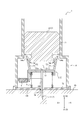
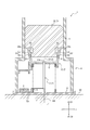
- FIGS. 1 to 4 are views showing an insertion device 1 as a first embodiment of the insertion device according to the present disclosure. Although details will be described later, each of FIGS. 1 to 4 shows an outline of the operation of the insertion device 1 when the medical device 100 is inserted and placed in the living body by using the insertion device 1.
- the insertion device 1 shown in FIGS. 1 to 4 can insert the sensor 100a as the medical device 100 into the living body.
- the insertion device 1 that inserts the sensor 100a as the medical device 100 into the living body will be described as an example, but the medical device 100 that is inserted into the living body by the insertion device 1 is not limited to the sensor 100a. Therefore, it may be an insertion device for inserting a tube member such as a cannula other than the sensor.
- the insertion device 1 includes a needle member 2, a moving member 3, a housing 4, an urging member 5, a control device 6, and a sensor 100a as a medical device 100. Be prepared.
- the needle member 2 of the present embodiment includes a needle portion 11 and a holding portion 12.
- the moving member 3 of the present embodiment includes a moving portion 21 and a main body portion 22.
- the insertion device 1 of the present embodiment can be used for inserting and indwelling the sensor 100a in the living body as described above.
- the insertion device 1 is arranged on the biological surface BS in the state shown in FIG. That is, FIG. 1 shows a state before the needle portion 11 of the needle member 2 and the sensor 100a are inserted into the living body. After that, when an operator such as a medical worker operates the insertion device 1, the needle portion 11 of the needle member 2 and the sensor 100a are inserted into the living body (see FIGS. 2 and 3).
- FIG. 1 shows a state before the needle portion 11 of the needle member 2 and the sensor 100a are inserted into the living body.
- FIG. 2 is a diagram showing a state in which the needle portion 11 and the sensor 100a are being inserted into the living body by the insertion device 1.
- FIG. 3 is a diagram showing a state in which the needle portion 11 and the sensor 100a have reached the deepest position in the living body that can be inserted by the insertion device 1.
- the needle portion 11 of the needle member 2 is removed from the living body while the sensor 100a is left in the living body. By doing so, the sensor 100a can be inserted and placed in the living body by the insertion device 1.
- the position of the needle portion 11 in FIG. 1 in which the needle portion 11 is housed in the housing 4 is referred to as a “standby position of the needle portion 11”.
- the position of the needle portion 11 in FIG. 3 in which the needle portion 11 protrudes most from the housing 4 is described as “the insertion position of the needle portion 11”.
- the sensor 100a placed in the living body detects the substance to be measured (analyte) and transmits the information of the detection result to, for example, the control device 6.
- the control device 6 is wiredly connected to the sensor 100a and is placed on the biological surface BS together with the sensor 100a.
- the control device 6 is composed of a processor, a memory, a battery, and the like.
- the sensor 100a of the present embodiment shown in FIGS. 1 to 4 transmits information on the detection result to the control device 6. By using the sensor 100a together with the control device 6, a signal can be detected according to the concentration of the substance to be measured.
- the detection signal is signal-processed by the control device 6 and transmitted to the smartphone of the person to be measured or a dedicated terminal.
- the person to be measured and the user can confirm the measurement result of the substance to be measured displayed on the screen of the smartphone or the dedicated terminal over time.
- the period during which the sensor 100a is attached to the subject is appropriately determined by the judgment of a doctor or the like, for example, several hours, several days, one week, or one month.
- the substance to be measured is not particularly limited, but glucose, oxygen, pH, lactic acid and the like in blood or interstitial fluid can be measured by selecting the detection unit of the sensor 100a.
- the control device 6 may be connected to a transmitter (not shown) provided as a separate body after the insertion of the sensor 100a is completed.
- the transmitter may have a memory, a battery, or the like instead of the control device 6. Further, the transmitter may be configured to be used for a longer period of time than the sensor 100a.
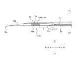
- FIG. 5 is a perspective view showing the needle portion 11 of the needle member 2, the moving portion 21 of the moving member 3, and the sensor 100a in the insertion device 1 in the state shown in FIG.
- the end of the needle member 2 on the side where the needle portion 11 is inserted into the living body will be referred to as "the tip of the needle portion 11".
- the end of the needle member 2 opposite to the tip of the needle portion 11 is referred to as the "base end of the needle portion 11".
- the direction from the base end to the tip end in the longitudinal direction A of the needle portion 11 of the needle member 2 is described as "insertion direction A1" or "tip side”.
- the direction from the tip to the proximal end in the longitudinal direction A of the needle portion 11 of the needle member 2 is described as "pulling direction A2" or "base end side”.
- the radial direction B of the needle portion 11 means the radial direction of the circle when a circle around the needle portion 11 centered on the needle portion 11 is defined in a plane orthogonal to the longitudinal direction A of the needle portion 11.
- the direction from the central axis of the needle portion 11 of the needle member 2 toward the outside is described as "outside the radial direction B".
- the direction from the circumference of the circle toward the central axis of the needle portion 11 is described as "inside the radial direction B".
- the "circle around the needle portion 11 of the needle member 2" substantially coincides with the inner peripheral surface of the third side plate portion 15c in the cross section of the needle portion 11 when the third side plate portion 15c is formed in an arc shape. ..
- the center of the circle around the needle portion 11 of the needle member 2 has a cross section orthogonal to the longitudinal direction A of the needle portion 11 of the third side plate portion 15c described later. It exists at a position equal to both ends (the ends where the third side plate portion 15c is connected to the first side plate portion 15a and the second side plate portion 15b, respectively).
- FIG. 6 is a view of the needle portion 11, the moving portion 21, and the sensor 100a shown in FIG. 5 as viewed from the tip side.
- FIG. 7A is a cross-sectional view taken along the line II of FIG. 5, showing the needle portion 11, the moving portion 21, and the medical device 100 in a state where the needle portion 11 of the insertion device 1 shown in FIG. 1 is in the standby position. is there.
- the needle portion 11 internally partitions a medical device accommodating space 13 capable of accommodating the medical instrument 100.
- the needle portion 11 is inserted into the living body together with the medical device 100 housed in the medical device storage space 13.
- the needle portion 11 of the present embodiment includes a side wall portion 15 for partitioning the medical device accommodating space 13.
- the side wall portion 15 of the present embodiment is continuous with the first side plate portion 15a and the second side plate portion 15b arranged to face each other and one end of each of the first side plate portion 15a and the second side plate portion 15b.
- a third side plate portion 15c and the like are provided.
- the medical device accommodating space 13 is partitioned by the first side plate portion 15a, the second side plate portion 15b, and the third side plate portion 15c.
- the side wall portion 15 extends in the longitudinal direction A.
- the first side plate portion 15a and the second side plate portion 15b are each formed of a long flat plate extending in the longitudinal direction A.
- the third side plate portion 15c extends in the longitudinal direction A together with the first side plate portion 15a and the second side plate portion 15b.
- the third side plate portion 15c is formed of an arc-shaped plate in a cross-sectional view orthogonal to the longitudinal direction A.
- the side wall portion 15 of the present embodiment forms a U-shaped groove by the first side plate portion 15a, the second side plate portion 15b, and the third side plate portion 15c.
- the cross-sectional outer shape orthogonal to the longitudinal direction A of the side wall portion 15 is not limited to the U-shaped groove shape as in the present embodiment, and may have a cross-sectional outer shape such as a rectangular shape or a C-shaped shape. Good.
- the third side plate portion 15c is formed in an appropriate shape such as a flat plate shape, a semicircular shape, or a substantially semicircular arc shape.
- the first side plate portion 15a and the second side plate portion 15b may also be formed in an arc shape in a cross-sectional view.
- the sensor 100a is wiredly connected to the control device 6 provided on the base plate 72.
- the sensor 100a can be pulled out from the medical device accommodating space 13 on the U-shaped opening (needle portion slit 20a) side. it can.
- a separate transmitter (not shown) is mounted on the base plate 72 having the sensor 100a, the control device 6 is housed in the transmitter and the contact point with the sensor 100a is at an arbitrary position of the transmitter. It can be configured to provide a portion.
- the tip of the side wall portion 15 has a blade edge 19a and a blade surface 19b.
- a cutting edge 19a is formed at the tip.
- the tip of the third side plate portion 15c constitutes the cutting edge 19a.
- a blade surface 19b formed of a slope inclined with respect to the longitudinal direction A is formed.
- the blade surface 19b is formed so as to taper toward the blade edge 19a.
- the blade surface 19b is formed so as to be inclined when the needle portion 11 is viewed from the side of the first side wall portion 15a.
- the shape of the slope may be a flat surface or a curved surface.
- the cutting edge 19a of the side wall portion 15 is not limited to this configuration.
- the side wall portion 15 may have, for example, one or more blade surfaces 19b whose tip is inclined with respect to the longitudinal direction A, or may have an asymmetric blade surface with respect to the central axis of the needle portion 11. ..
- the facing width between the outer surfaces of the first side plate portion 15a and the second side plate portion 15b of the side wall portion 15 can be, for example, 0.2 mm to 0.6 mm.
- the length of the side wall portion 15 to be inserted into the living body can be, for example, 1 mm to 10 mm, preferably 3 to 6 mm.
- the thickness of the first side plate portion 15a, the second side plate portion 15b, and the third side plate portion 15c is set, for example, from the range of 0.02 mm to 0.15 mm.
- the detection unit 100b of the sensor 100a is provided in the vicinity of the tip 100e of the sensor 100a.
- the detection unit 100b is provided slightly closer to the base end side than the tip end 100e.
- At least a part of the medical device 100 is fixed to the needle portion 11.
- at least a part of the sensor 100a as the medical device 100 is adhesively fixed to the side wall portion 15.
- a part of the sensor 100a is adhesively fixed to the third side plate portion 15c.
- the portion of the sensor 100a on the base end side of the detection portion 100b is adhesively fixed to the third side plate portion 15c of the side wall portion 15.
- the region where the sensor 100a and the third side plate portion 15c are adhesively fixed is shown as an adhesive region D in FIG. 7A.
- the adhesive region D is at least a part of the side surface of the sensor 100a that comes into contact with the side wall portion 15, and refers to a region fixed to the side wall portion 15.
- An adhesive is applied to a position on the surface of the sensor 100a corresponding to the adhesive region D.
- the sensor 100a can be inserted together with the needle portion 11 at a desired depth in the living body.
- the type of adhesive used here may be any that has biocompatibility, and the amount of the adhesive can maintain the adhesive strength required for inserting the sensor 100a and the needle portion 11 into the living body. Any amount is sufficient.
- a metal material such as stainless steel, aluminum, aluminum alloy, titanium, titanium alloy, magnesium alloy can be used.
- a material that can be manufactured by plastic working is selected.
- plastic working a drawing pipe having a predetermined inner diameter can be cut, or a metal flat plate can be manufactured by pressing.
- a material to which press working can be applied is selected as the material of the needle portion 11.
- the holding portion 12 holds the base end portion of the needle portion 11.
- the holding portion 12 of the present embodiment includes a main body portion 51 and a locking claw portion 52.
- the main body 51 includes a holding opening 51a that penetrates in the longitudinal direction A.
- the base end portion of the needle portion 11 is fixed to the main body portion 51 in a state of being inserted into the holding opening 51a.
- the locking claw portion 52 projects from the main body portion 51 in the removal direction A2.
- the locking claw portion 52 is located outside the needle portion 11 in the radial direction B of the needle portion 11. Further, in the needle member 2 of the present embodiment, a plurality of locking claw portions 52 are provided on the outer side of the needle portion 11 in the radial direction B so as to surround the periphery of the needle portion 11.
- the locking claw portion 52 includes an extending portion 53 projecting from the main body portion 51, and an engaging convex portion 54 provided at the end of the extending portion 53 in the removal direction A2.
- the extending portion 53 can be elastically deformed in a direction orthogonal to the longitudinal direction A with a position continuous with the main body portion 51 as a fulcrum. More specifically, the extending portion 53 of the present embodiment can be elastically deformed in the radial direction B of the needle portion 11 with a position continuous with the main body portion 51 as a fulcrum.
- the engaging convex portion 54 projects from the end of the extending portion 53 in a direction orthogonal to the longitudinal direction A.
- the upper surface 54a located in the removal direction A2 of the engaging convex portion 54 is inclined with respect to the longitudinal direction A so as to extend inward in the radial direction B toward the insertion direction A1.
- the upper surface 54a of the engaging convex portion 54 is pressed outward in the radial direction B by engaging with the main body portion 22 described later of the moving member 3. The details will be described later.
- Examples of the material of the holding portion 12 include a resin material.
- the resin material include ABS resin, AS resin, polyethylene, polypropylene, polystyrene, polyvinyl chloride, polyvinylidene chloride resin, polyphenylene oxide, thermoplastic polyurethane, polymethylene methacrylate, polyoxyethylene, fluororesin, polycarbonate, and polyamide.
- the moving member 3 of the present embodiment includes a moving portion 21 and a main body portion 22.
- the moving portion 21 is movable relative to the needle portion 11 in the medical device accommodating space 13 in the insertion direction A1 of the needle portion 11. Further, the moving portion 21 cuts the adhesive region D between the medical device 100 and the needle portion 11 by moving in the insertion direction A1 with respect to the needle portion 11. Specifically, the tip 21e of the moving portion 21 comes into contact with the base end portion side of the adhesive region D, thereby separating the medical device 100 and the needle portion 11 in the adhesive region D. As a result, the adhesive state between the medical device 100 and the needle portion 11 is released, so that the medical device 100 is released from being fixed to the needle portion 11. Specifically, the moving portion 21 of the present embodiment moves in the insertion direction A1 with respect to the needle portion 11.
- the cutting edge 21e forming the tip of the moving portion 21 comes into contact with the base end of the adhesive region D. From this state, the moving portion 21 further moves in the insertion direction A1, so that the medical device 100 and the needle portion 11 are separated from the base end to the tip end of the adhesive region D. As a result, the medical device 100 is released from being fixed to the needle portion 11. At this time, the moving portion 21 enters between the medical device 100 and the needle portion 11.
- the moving portion 21 of the present embodiment is a member extending in the longitudinal direction A along the inner peripheral surface of the side wall portion 15 of the needle portion 11 in the medical device accommodating space 13. It is configured. Specifically, the moving portion 21 extends along the longitudinal direction A of the needle portion 11 and includes a first groove wall portion 21a, a second groove wall portion 21b, and a third groove wall portion 21c. The first groove wall portion 21a and the second groove wall portion 21b are arranged so as to face each other. The third groove wall portion 21c is continuous with one end of each of the first groove wall portion 21a and the second groove wall portion 21b.
- the groove space 23 is partitioned by the first groove wall portion 21a, the second groove wall portion 21b, and the third groove wall portion 21c.
- the moving portion 21 can hold the medical device 100 in the groove space 23.
- the first groove wall portion 21a and the second groove wall portion 21b are made of a flat plate, and the third groove wall portion 21c is made of a plate on an arc.
- a blade surface 21f formed of a slope inclined with respect to the longitudinal direction A is formed so that the tip of the third groove wall portion 21c becomes a sharp cutting edge 21e.
- the configuration of the cutting edge 21e of the moving portion 21 is not limited to the configuration of the present embodiment.
- the shapes of the first groove wall portion 21a, the second groove wall portion 21b, and the third groove wall portion 21c are not limited to the above-mentioned shapes.
- the first groove wall portion 21a, the second groove wall portion 21b, and the third groove wall portion 21c may be formed in such a shape that the moving portion 21 can separate the adhesive region D. Further, it is preferable that the first groove wall portion 21a, the second groove wall portion 21b and the third groove wall portion 21c are configured so that the moving portion 21 has a shape along the side wall portion 15 as a whole.
- the moving portion 21 also has an opening (moving portion slit 20b) capable of pulling out the base end portion of the sensor 100a as the medical device 100 from the moving portion 21 toward the outside of the moving portion 21. ..
- the moving portion 21 may be formed in a tubular shape having no opening.
- the material of the moving portion 21 for example, a metal material such as stainless steel, aluminum, aluminum alloy, titanium, titanium alloy, magnesium alloy can be used.
- the moving portion 21 can be manufactured by plastic working.
- the moving portion 21 can be manufactured, for example, by cutting a drawing pipe having a predetermined inner diameter or by pressing a metal flat plate.
- the main body 22 holds the end of the moving portion 21 in the removal direction A2.
- the main body 22 of the present embodiment is movably attached in the housing 4 in the longitudinal direction A.
- the upper surface of the main body 22 of the present embodiment is exposed to the outside from the housing 4 in the removal direction A2. Therefore, the operator of the insertion device 1 can move the main body 22 in the insertion direction A1 by pressing the main body 22 exposed from the housing 4 in the insertion direction A1.
- the moving portion 21 attached to the main body portion 22 can also move in the medical device accommodating space 13 of the needle portion 11 in the insertion direction A1. That is, the main body 22 also serves as an operation unit of the insertion device 1.
- the main body portion 22 includes an engaging portion 61 that presses the locking claw portion 52 of the holding portion 12 of the needle member 2 to the outside of the needle portion 11 in the radial direction B. Further, the main body portion 22 defines an engaging recess 62 into which the engaging convex portion 54 of the locking claw portion 52 can be fitted at a position adjacent to the pulling direction A2 of the engaging portion 61.
- the engaging recess 62 is recessed inward in the radial direction B with respect to the engaging portion 61.
- the engaging portion 61 is composed of, for example, a disk portion. Further, as shown in FIGS.
- the engaging recess 62 is adjacent to, for example, the extraction direction A2 of the disk portion as the engaging portion 61, and is inward in the radial direction B from the outer edge of the disk portion. It is composed of an annular groove that is recessed.
- the configuration of the engaging portion 61 and the engaging recess 62 is not limited to the shape and position shown in this embodiment.
- the insertion device 1 of the present embodiment can insert the needle portion 11 and the sensor 100a into the living body by pushing the main body portion 22 in the insertion direction A1.
- the engaging portion 61 of the main body portion 22 engages with the upper surface 54a located in the removing direction A2 of the engaging convex portion 54 of the locking claw portion 52, and the engaging convex portion 54 is outside the radial direction B. Press on.
- the extending portion 53 of the locking claw portion 52 is elastically deformed to the outside in the radial direction B.
- the plurality of locking claw portions 52 located around the outer side of the needle portion 11 in the radial direction B are elastically deformed so as to be separated from the outer side in the radial direction B. Therefore, as shown in FIG. 3, the engaging portion 61 of the main body portion 22 can get over the engaging convex portion 54 in the insertion direction A1 while sliding with the upper surface 54a of the engaging convex portion 54.
- the engaging convex portion 54 fits into the engaging concave portion 62 of the main body portion 22. ..
- the main body 22 of the moving member 3 and the holding portion 12 of the needle member 2 interfere with each other in the longitudinal direction A. That is, the needle member 2 and the moving member 3 can move together in the longitudinal direction A.
- the inner surface of the engaging recess 62 of the main body 22 of the moving member 3 in the insertion direction A1 becomes the engaging convex portion 54 of the holding portion 12 of the needle member 2. Abuts on the outer surface of the insertion direction A1.
- the needle member 2 and the moving member 3 can be integrated and both can be moved in the removal direction A2. Therefore, as shown in FIG. 4, when the needle portion 11 is removed from the living body, the moving portion 21 in the needle portion 11 can be removed from the living body together with the needle portion 11.
- Examples of the material of the main body 22 include a resin material.
- the resin material include ABS resin, AS resin, polyethylene, polypropylene, polystyrene, polyvinyl chloride, polyvinylidene chloride resin, polyphenylene oxide, thermoplastic polyurethane, polymethylene methacrylate, polyoxyethylene, fluororesin, polycarbonate, and polyamide.
- the housing 4 is an exterior member that covers the needle member 2, the moving member 3, the urging member 5, the control device 6, and the sensor 100a described later. As shown in FIGS. 1 to 4, in the housing 4 of the present embodiment, the needle member 2, the moving member 3, the urging member 5, and the control device 6 are in a state where the needle portion 11 is in the standby position (see FIG. 1).
- a tubular member 71 that covers the periphery of the sensor 100a in the radial direction B, which will be described later, and a base plate 72 that covers the end surface of the tubular member 71 in the insertion direction A1.
- the base plate 72 is removable from the tubular member 71.
- the surface of the base plate 72 on the insertion direction A1 side constitutes a contact surface 72a that comes into contact with the biological surface BS when the needle portion 11 and the sensor 100a are inserted into the living body.
- the base plate 72 is formed with a through hole 74 penetrating in the longitudinal direction A.
- the needle portion 11 in the standby position moves to the insertion position (see FIG. 3)
- the needle portion 11 projects from the contact surface 72a through the through hole 74 in the insertion direction A1.
- the contact surface 72a is provided with a sticking portion for indwelling on the biological surface BS.
- the configuration of the housing 4 is not particularly limited.
- the needle member 2 and the moving member 3 are movably attached to the housing 4 in the longitudinal direction A, but may be movably attached to a member different from the housing 4.
- the insertion device 1 of the present embodiment includes the housing 4, the insertion device 1 may not include the housing 4. However, like the housing 4 of the present embodiment, the insertion device 1 prevents a medical worker, a patient, or the like from accidentally touching the needle portion 11, so that the insertion device 1 is outside the radial direction B of the needle portion 11 in the standby position. It is preferable to provide a member that covers at least the periphery of the.
- the housing 4 of the present embodiment has a structure in which the tubular member 71 and the base plate 72 are removable, but the structure is not limited to this, and both may be integrally formed. However, by making both of them removable, it is easy to reduce the size of the portion placed on the biological surface BS, and the burden on the person to be measured can be reduced.
- Examples of the material of the housing 4 include a resin material.
- the resin material include ABS resin, AS resin, polyethylene, polypropylene, polystyrene, polyvinyl chloride, polyvinylidene chloride resin, polyphenylene oxide, thermoplastic polyurethane, polymethylene methacrylate, polyoxyethylene, fluororesin, polycarbonate, and polyamide.
- the urging member 5 of this embodiment is elastically deformable in the longitudinal direction A.
- the urging member 5 of the present embodiment is a coil spring that elastically deforms in the longitudinal direction A.
- the coil spring as the urging member 5 is arranged between the holding portion 12 of the needle member 2 and the base plate 72 of the housing 4. Therefore, the coil spring as the urging member 5 of the present embodiment is compressed and deformed when the needle portion 11 moves from the standby position (see FIG. 1) to the insertion position (see FIG. 3). Further, by releasing the restoring force of the coil spring as the urging member 5 while the needle portion 11 is in the insertion position (see FIG. 3), the needle portion 11 is moved from the insertion position (see FIG. 3) to the removal direction A2. Can be made to.
- the above-mentioned needle member 2 and moving member 3 resist the restoring force of the coil spring as the urging member 5. And move it in the insertion direction A1.
- the needle member 2 and the moving member 3 move in the insertion direction A1, and the needle portion 11 and the sensor 100a are inserted into the living body.
- the pressing force in the insertion direction A1 applied to the needle member 2 and the moving member 3 is released, so that the restoring force of the coil spring as the urging member 5 is restored.
- the needle member 2 and the moving member 3 move in the removal direction A2.
- the needle portion 11 can be removed from the living body while the sensor 100a is left in the living body.
- the restoring force of the coil spring as the urging member 5 causes the needle portion 11 to return from the insertion position (see FIG. 3) to the position where it is housed in the housing 4 (for example, the same standby position as in FIG. 1). (See FIG. 4).
- the urging member 5 of the present embodiment is composed of a coil spring, but for example, another elastic member may be used and is not limited to the coil spring. Further, the insertion device 1 may be configured not to include the urging member 5.
- the control device 6 is operably connected to the sensor 100a. Therefore, the control device 6 can receive the detection information of the sensor 100a from the sensor 100a placed in the living body. Further, as described above, the control device 6 analyzes the detection signal received from the sensor 100a and transmits the analysis result to an external device such as a display device as needed.
- the control device 6 is composed of a processor, a memory, a battery, and the like.
- the control device 6 may be provided not on the base plate 72 but on a separate transmitter side that can be combined with the base plate 72. In this case, a contact portion with the transmitter is provided at the position of the control device 6 in FIGS. 1 to 4 instead of the control device 6.
- the control device 6 of the present embodiment moves in the insertion direction A1 together with the needle portion 11 and the sensor 100a. More specifically, the control device 6 of the present embodiment is held by the needle member 2 in a state where the needle portion 11 is in the standby position (see FIG. 1). When the needle portion 11 moves from the standby position (see FIG. 1) to the insertion position (see FIG. 3), the control device 6 moves together with the needle member 2 in the insertion direction A1. When the needle portion 11 reaches the insertion position (see FIG. 3), the control device 6 engages with the base plate 72 of the housing 4 and the state held by the needle member 2 is released.
- any means such as adhesion or mechanical engaging can be adopted.
- the control device 6 is held on the base plate 72. Therefore, when the needle portion 11 is removed from the living body, that is, when the needle portion 11 returns from the insertion position to the standby position, the needle member 2 moves in the removal direction A2, but the control device 6 controls the removal direction A2. It does not move to and is left on the base plate 72 of the housing 4.
- the sensor 100a of the present embodiment is a small-diameter linear member housed in the medical device accommodating space 13 of the needle portion 11.
- a member that detects an electrical signal according to the amount or concentration of the substance to be measured can be used.
- the sensor 100a extends along the longitudinal direction A of the needle portion 11 in the medical device accommodating space 13.
- the sensor 100a may be, for example, a wire electrode having a circular cross-sectional shape.
- the wire electrode is accommodated in the medical device accommodating space 13 of the needle portion 11.
- the outer diameter of the wire electrode can be, for example, 0.02 mm to 0.2 mm.
- the medical device accommodating space 13 may accommodate, for example, two wire electrodes, a working electrode and a reference electrode.
- the working electrode is composed of a core material having a conductive surface as a base, and the detection unit 100b configured to detect the substance to be measured on the outer wall of the core material and the outer wall of the core material are coated with an insulating material. It may be configured to include the protected protection unit.
- the detection unit 100b can detect a change in electrical characteristics with respect to the material to be measured.
- the detection unit 100b is formed on the surface of the core material by using a thin film forming means such as dipping, electrolytic polymerization, or sputtering.
- a reagent that specifically reacts with the substance to be measured is applied to the surface of the working electrode.
- the substance to be measured is glucose
- a reagent containing glucose oxidase or a phenylboronic acid compound is used.
- the reference electrode is used as a reference electrode for the working electrode described above.
- a reference electrode or a counter electrode may be wound around the working electrode in a coil shape to form a single wire electrode. Alternatively, three wire electrodes may be arranged in the medical device accommodation space 13.
- a working electrode, a reference electrode and a counter electrode may be formed by each of the three wire electrodes. Further, the needle portion 11 itself may be used as the reference electrode or the counter electrode.
- Information on the substance to be measured detected by the detection unit 100b of the working electrode is transmitted to the control device 6.
- FIG. 7A is a cross-sectional view taken along the line II of FIG. 5, showing the needle portion 11, the moving portion 21, and the sensor 100a as the medical device 100 in a state where the needle portion 11 is in the standby position (see FIG. 1).
- FIG. 7B is a diagram showing the needle portion 11, the moving portion 21, and the sensor 100a in a state where the needle portion 11 is in the process of moving from the standby position (see FIG. 1) to the insertion position (see FIG. 3).
- FIG. 7A is a cross-sectional view taken along the line II of FIG. 5, showing the needle portion 11, the moving portion 21, and the sensor 100a as the medical device 100 in a state where the needle portion 11 is in the standby position (see FIG. 1).
- FIG. 7B is a diagram showing the needle portion 11, the moving portion 21, and the sensor 100a in a state where the needle portion 11 is in the process of moving from the standby position (see FIG. 1) to the insertion position (see FIG. 3).
- FIG. 7C is a diagram showing the needle portion 11, the moving portion 21, and the sensor 100a in a state where the needle portion 11 is in the insertion position (see FIG. 3).
- FIG. 7D is a diagram showing the needle portion 11, the moving portion 21, and the sensor 100a in a state where the needle portion 11 is in the process of returning to the inside of the housing 4 after the sensor 100a is placed at the insertion position (see FIG. 3).
- 7B to 7D are the same cross-sectional views as those in FIG. 7A.
- the needle portion 11 when the needle portion 11 is in the standby position (see FIG. 1), a part of the sensor 100a as the medical device 100 is adhesively fixed to the side wall portion 15. Specifically, the sensor 100a and the side wall portion 15 are adhesively fixed in the adhesive region D located on the proximal end side of the detection portion 100b. As a result, even if the sensor 100a has a small diameter, the detection unit 100b of the sensor 100a is held without protruding from the U-shaped needle portion slit 20a of the needle portion 11.
- both the needle member 2 and the moving member 3 move in the insertion direction A1. To do. Further, as shown in FIGS. 1 to 3, while the needle portion 11 is moving from the standby position (see FIG. 1) to the insertion position (see FIG. 3), the needle member 2 and the moving member 3 are relative to each other in the longitudinal direction A. Positional relationship also fluctuates. That is, while the needle portion 11 is moving from the standby position (see FIG. 1) to the insertion position (see FIG. 3), both the needle member 2 and the moving member 3 move in the insertion direction A1, and the moving member 3 moves.
- FIG. 7B shows a state in which the adhesive state between the sensor 100a and the side wall portion 15 is broken by the moving portion 21 and the sensor 100a is separated from the side wall portion 15.
- the moving member 3 moves relative to the needle member 2 so as to be closer to the insertion direction A1, and at the insertion position (see FIG. 3), FIG.
- the positional relationship is as shown in 7C.
- the needle portion 11 returns from the insertion position (see FIG. 3) to the position where it is housed in the housing 4 (for example, the same standby position as in FIG. 1). As shown in FIG. 7D, the needle portion 11 is removed from the living body together with the moving portion 21 while the sensor 100a is indwelled in the living body.
- the adhesive state between the medical device 100 and the side wall portion 15 is released when the medical device 100 reaches a predetermined depth in the living body. Therefore, the medical device 100 can be easily placed at a predetermined depth in the living body.
- FIG. 8 is a perspective view showing the needle portion 11 of the needle member 2, the moving portion 21 of the moving member 3, and the sensor 100a in the insertion device as the second embodiment different from the above-mentioned insertion device 1.
- the same points as those in the first embodiment will be described with respect to the configuration according to the second embodiment, omitting appropriate explanations.
- the configuration of the sensor 100a as the medical device 100 is the same as that of the first embodiment, and therefore detailed description thereof will be omitted.
- FIG. 9 is a sectional view taken along line II-II of the needle portion 11, the moving portion 21, and the medical device 100 shown in FIG. 8 orthogonal to the longitudinal direction A.
- FIG. 10A is a cross-sectional view taken along the line III-III of FIG. 8, showing the needle portion 11, the moving portion 21, and the medical device 100 in a state where the needle portion 11 of the insertion device 1 shown in FIG. 1 is in the standby position. is there.
- the needle portion 11 is formed by the wall portion 16 in a tubular shape extending along the longitudinal direction A.
- An opening (slit) 24 having a width that allows the medical device 100 to be detached is provided on the tip end side of the needle portion 11.
- the wall portion 16 has a mounting surface on which a part of the medical device 100 is mounted on a part of the outer peripheral surface.
- the outer peripheral surface of the wall portion 16 is substantially crescent-shaped, and the surface recessed in the wall portion 16 is formed. Consists of the mounting surface 17.
- the mounting surface 17 is not provided on the tip end side of the needle portion 11.
- a part of the sensor 100a is fixed to the needle portion 11 on the tip side where the mounting surface 17 is not provided.
- a part of the sensor 100a is fixed on the inner peripheral surface of the wall portion 16 on the distal end side where the mounting surface 17 is not provided.
- a part of the sensor 100a is adhesively fixed by, for example, an adhesive.
- the portion of the sensor 100a on the proximal end side of the detection portion 100b is adhesively fixed to the inner peripheral surface of the wall portion 16.
- the region where the sensor 100a and the inner peripheral surface of the wall portion 16 are adhesively fixed is shown as an adhesive region D in FIG. 10A.
- At least a part of the sensor 100a that is not adhered to the needle portion 11 is mounted on the mounting surface 17.
- the portion of the sensor 100a on the base end side of the adhesive region D is mounted on the mounting surface 17. Since the needle portion 11 has the mounting surface 17, the sensor 100a can be stably mounted on the needle portion 11.
- the needle portion 11 is adhesively fixed in the adhesive region D and is inserted into the living body together with the sensor 100a mounted on the mounting surface 17.
- the wall portion 16 partitions the moving portion accommodating space 18 accommodating the moving portion 21 inside the tube-shaped needle portion 11.
- the moving portion 21 is slidable in the moving portion accommodating space 18.
- the moving portion accommodating space 18 extends along the longitudinal direction A.
- the moving portion accommodating space 18 is substantially crescent-shaped in a cross-sectional view orthogonal to the longitudinal direction A.
- the wall portion 16 is formed to have a substantially uniform thickness, and the moving portion accommodating space 18 is configured to have the same shape as the outer peripheral surface of the wall portion 16.
- a blade edge 16a is formed at the tip of the wall portion 16 by the blade surface 16b.
- a portion of the wall portion 16 facing the portion forming the mounting surface 17 (the lower portion in FIGS. 9 and 10A; hereinafter, referred to as “lower wall portion”).
- the cutting edge is formed at the tip of the.
- the wall portion 16 of the present embodiment is configured to include one blade surface whose tip surface is inclined with respect to the longitudinal direction A, but the shape of the blade edge is not particularly limited.
- the portion of the sensor 100a on the proximal end side of the detection portion 100b is adhesively fixed to the wall portion 16.
- the sensor 100a is inserted into the living body together with the needle portion 11. Therefore, the sensor 100a can be inserted at a desired depth in the living body.
- the material of the needle portion 11 for example, a metal material such as stainless steel, aluminum, aluminum alloy, titanium, titanium alloy, magnesium alloy can be used as in the first embodiment. Further, as in the first embodiment, the base end side of the needle portion 11 is held by the holding portion 12. The needle portion 11 can be manufactured by press working.
- the moving portion 21 is movable relative to the needle portion 11 in the medical device accommodating space 13 in the insertion direction A1 of the needle portion 11. Further, the moving portion 21 cuts the adhesive region D between the medical device 100 and the needle portion 11 by moving in the insertion direction A1 with respect to the needle portion 11. Specifically, when the tip of the moving portion 21 comes into contact with the proximal end side of the adhesive region D, the adhesion is broken on the proximal end side of the adhesive region D. Further, the cutting edge 21e of the moving portion 21 moves in the insertion direction A1 to peel off the medical device 100 from the side wall portion 15 from the proximal end side to the distal end side of the adhesive region D.
- the adhesive state between the medical device 100 and the needle portion 11 is released, and the medical device 100 is separated from the needle portion 11.
- the moving portion 21 of the present embodiment moves in the insertion direction A1 with respect to the needle portion 11, and the cutting edge 21e forming the tip of the moving portion 21 comes into contact with the adhesive region D.
- the adhesive region D is cut in the insertion direction A1 and the medical device 100 is peeled off from the needle portion 11.
- the moving portion 21 of the present embodiment is configured as a member extending along the longitudinal direction A in the moving portion accommodating space 18.
- the cross section is configured to have a curved plate shape in accordance with the shape of the moving portion accommodating space 18.
- a cutting edge 21e is formed at the tip of the moving portion 21. More specifically, the moving portion 21 of the present embodiment is configured to include one blade surface that is inclined with respect to the longitudinal direction A, but the shape of the blade edge is not particularly limited.
- the moving portion 21 moves in the insertion direction A1 with respect to the needle portion 11, the cutting edge 21e comes into contact with the adhesive region D, and the moving portion 21 is further moved between the medical device 100 (sensor 100a) and the needle portion 11. By invading, the adhesive region D is destroyed. As a result, the sensor 100a and the needle portion 11 are separated from each other.
- a metal material such as stainless steel, aluminum, aluminum alloy, titanium, titanium alloy, or magnesium alloy can be used as in the first embodiment. Further, as in the first embodiment, the end portion of the moving portion 21 in the removal direction A2 is held by the main body portion 22.
- the moving portion 21 can be manufactured by plastic working. For example, a drawing pipe having a predetermined inner diameter can be cut, or a metal flat plate can be manufactured by pressing.
- FIG. 10A is a sectional view taken along line III-III of FIG. 8, showing the needle portion 11, the moving portion 21, and the sensor 100a in a state where the needle portion 11 is in the standby position (see FIG. 1).
- FIG. 10B is a diagram showing the needle portion 11, the moving portion 21, and the sensor 100a in a state where the needle portion 11 is in the process of moving from the standby position (see FIG. 1) to the insertion position (see FIG. 3).
- FIG. 10A is a sectional view taken along line III-III of FIG. 8, showing the needle portion 11, the moving portion 21, and the sensor 100a in a state where the needle portion 11 is in the standby position (see FIG. 1).
- FIG. 10B is a diagram showing the needle portion 11, the moving portion 21, and the sensor 100a in a state where the needle portion 11 is in the process of moving from the standby position (see FIG. 1) to the insertion position (see FIG. 3).
- 10C is a diagram showing the needle portion 11, the moving portion 21, and the sensor 100a in a state where the needle portion 11 is in the insertion position (see FIG. 3).
- FIG. 10D is a diagram showing the needle portion 11, the moving portion 21, and the sensor 100a in a state where the needle portion 11 is in the process of returning to the inside of the housing 4 after the sensor 100a is placed at the insertion position (see FIG. 3).
- 10B to 10D are the same cross-sectional views as those in FIG. 10A.
- the sensor 100a as the medical device 100 is adhesively fixed to the inner peripheral surface of the wall portion 16.
- the sensor 100a and the wall portion 16 are adhesively fixed in the adhesive region D on the proximal end side of the detection portion 100b.
- the adhesive and the adhesive fixing method are the same as those in the first embodiment.
- both the needle member 2 and the moving member 3 move in the insertion direction A1. To do. Further, as shown in FIGS. 1 to 3, while the needle portion 11 is moving from the standby position (see FIG. 1) to the insertion position (see FIG. 3), the needle member 2 and the moving member 3 are relative to each other in the longitudinal direction A. Positional relationship also fluctuates. That is, while the needle portion 11 is moving from the standby position (see FIG. 1) to the insertion position (see FIG. 3), both the needle member 2 and the moving member 3 move in the insertion direction A1, and the moving member 3 moves.
- FIG. 10B shows a state in which the adhesion between the sensor 100a and the wall portion 16 is released by the moving portion 21.
- the moving member 3 moves relative to the needle member 2 so as to be closer to the insertion direction A1, and at the insertion position (see FIG. 3), FIG.
- the positional relationship is as shown in 10C.
- the needle portion 11 returns from the insertion position (see FIG. 3) to the position where it is housed in the housing 4 (for example, the same standby position as in FIG. 1). As shown in FIG. 10D, the needle portion 11 is removed from the living body together with the moving portion 21 while the sensor 100a is indwelled in the living body.
- the adhesive state between the medical device 100 and the side wall portion 15 is released when the medical device 100 reaches a predetermined depth in the living body. Therefore, the medical device 100 can be easily placed at a predetermined depth in the living body.
- the insertion device 1 according to the first embodiment and the second embodiment described above may have further other configurations.
- the insertion device 1 according to the first embodiment and the second embodiment may include a regulating mechanism that regulates the relative movement of the needle portion 11 and the moving portion 21 other than the longitudinal direction A.
- the regulatory mechanism will be described.
- FIG. 11 is a sectional view taken along line IV-IV of FIG. 7A.
- a rib 44 projecting toward the medical device accommodating space 13 is provided on the inner surface of the needle portion 11. More specifically, a rib 44 that projects toward the medical device accommodating space 13 and extends in the longitudinal direction A is formed on the inner surface of the third side plate portion 15c on the side wall portion 15 of the needle portion 11.
- a receiving groove 25 extending in the longitudinal direction A is formed on the outer surface of the moving portion 21. More specifically, a receiving groove 25 extending in the longitudinal direction A is formed on the outer surface of the third groove wall portion 21c of the moving portion 21.
- the rib 44 is fitted with the receiving groove 25 in the moving portion 21, and together with the receiving groove 25, constitutes the regulating mechanism 80.
- the rib 44 may be provided at least in a part of the needle portion 11 in the longitudinal direction A.
- FIG. 12 is a VV cross-sectional view of FIG. 10A.
- the inner peripheral surface of the wall portion 16 constituting the needle portion 11 projects toward the moving portion accommodating space 18.
- Ribs 44 are provided. Specifically, a rib 44 that protrudes toward the moving portion accommodating space 18 and extends in the longitudinal direction A is formed on the inner peripheral surface side of the lower wall portion of the wall portion 16.
- the moving portion 21 has a receiving groove 25 extending in the longitudinal direction A on the bottom surface side in contact with the lower wall portion of the wall portion 16.
- the rib 44 is fitted with the receiving groove 25 in the moving portion 21, and together with the receiving groove 25, constitutes the regulating mechanism 80.
- the rib 44 may be provided at least in a part of the needle portion 11 in the longitudinal direction A.
- the regulation mechanism 80 is not limited to the example shown here, and the specific configuration is particularly limited as long as it regulates the relative movement of the needle portion 11 and the moving portion 21 other than the longitudinal direction A. It's not a thing.
- the insertion device according to the present disclosure is not limited to the specific configuration / process shown in the above-described embodiment, and can be variously modified / changed as long as it does not deviate from the description of the scope of claims.
- This disclosure relates to an insertion device.
- Inserting device 2 Needle member 3: Moving member 4: Housing 5: Biasing member 6: Control device 11: Needle part 12: Holding part 13: Medical instrument accommodating space 15: Side wall part 15a: First side plate part 15b: Second side plate part 15c: Third side plate part 16: Wall part 17: Mounting surface 18: Moving part accommodating space 16a, 19a, 21e: Cutting edge 19b, 21f: Blade surface 20a: Needle part slit 20b: Moving part slit 21: Moving part 21a: First groove wall part 21b: Second groove wall part 21c: Third groove wall part 22: Main body part 23: Groove space 24: Opening 25: Receiving groove 44: Rib 51: Main body 51a: Holding opening 52: Locking claw portion 53: Extension portion 54: Engagement convex portion 54a: Upper surface 61: Engagement portion 62: Engagement recess 71: Cylindrical member 72: Base plate 72a: Contact surface 74: Through hole 80: Regulation Mechanism 100: Medical instrument 100a: Sensor 100b: Detection part
Landscapes
- Health & Medical Sciences (AREA)
- Life Sciences & Earth Sciences (AREA)
- Physics & Mathematics (AREA)
- Medical Informatics (AREA)
- Surgery (AREA)
- Engineering & Computer Science (AREA)
- Biomedical Technology (AREA)
- Heart & Thoracic Surgery (AREA)
- Biophysics (AREA)
- Molecular Biology (AREA)
- Pathology (AREA)
- Animal Behavior & Ethology (AREA)
- General Health & Medical Sciences (AREA)
- Public Health (AREA)
- Veterinary Medicine (AREA)
- Optics & Photonics (AREA)
- Emergency Medicine (AREA)
- Measurement Of The Respiration, Hearing Ability, Form, And Blood Characteristics Of Living Organisms (AREA)
- Infusion, Injection, And Reservoir Apparatuses (AREA)
Priority Applications (4)
| Application Number | Priority Date | Filing Date | Title |
|---|---|---|---|
| CN202080012190.2A CN113382681B (zh) | 2019-08-29 | 2020-08-05 | 插入装置 |
| EP20857821.1A EP4005478A4 (en) | 2019-08-29 | 2020-08-05 | INSERTION DEVICE |
| JP2021542693A JP7562541B2 (ja) | 2019-08-29 | 2020-08-05 | 挿入装置 |
| US17/513,508 US12285249B2 (en) | 2019-08-29 | 2021-10-28 | Insertion device |
Applications Claiming Priority (2)
| Application Number | Priority Date | Filing Date | Title |
|---|---|---|---|
| JP2019-157203 | 2019-08-29 | ||
| JP2019157203 | 2019-08-29 |
Related Child Applications (1)
| Application Number | Title | Priority Date | Filing Date |
|---|---|---|---|
| US17/513,508 Continuation US12285249B2 (en) | 2019-08-29 | 2021-10-28 | Insertion device |
Publications (1)
| Publication Number | Publication Date |
|---|---|
| WO2021039334A1 true WO2021039334A1 (ja) | 2021-03-04 |
Family
ID=74684484
Family Applications (1)
| Application Number | Title | Priority Date | Filing Date |
|---|---|---|---|
| PCT/JP2020/030088 Ceased WO2021039334A1 (ja) | 2019-08-29 | 2020-08-05 | 挿入装置 |
Country Status (5)
| Country | Link |
|---|---|
| US (1) | US12285249B2 (https=) |
| EP (1) | EP4005478A4 (https=) |
| JP (1) | JP7562541B2 (https=) |
| CN (1) | CN113382681B (https=) |
| WO (1) | WO2021039334A1 (https=) |
Cited By (1)
| Publication number | Priority date | Publication date | Assignee | Title |
|---|---|---|---|---|
| JPWO2023032047A1 (https=) * | 2021-08-31 | 2023-03-09 |
Citations (4)
| Publication number | Priority date | Publication date | Assignee | Title |
|---|---|---|---|---|
| WO2014162383A1 (ja) * | 2013-04-01 | 2014-10-09 | テルモ株式会社 | センサ留置デバイス及び生体情報測定システム |
| WO2016120920A1 (ja) * | 2015-01-27 | 2016-08-04 | テルモ株式会社 | センサ挿入装置セット及びベースプレート |
| WO2018218236A1 (en) * | 2017-05-26 | 2018-11-29 | Piper Access, Llc | Catheter delivery devices, systems, and methods |
| JP2019507613A (ja) | 2015-12-30 | 2019-03-22 | デックスコム・インコーポレーテッド | 経皮分析物センサシステム及び方法 |
Family Cites Families (3)
| Publication number | Priority date | Publication date | Assignee | Title |
|---|---|---|---|---|
| WO2016120919A1 (ja) * | 2015-01-27 | 2016-08-04 | テルモ株式会社 | センサ挿入装置及びセンサ挿入装置セット |
| JP2017118911A (ja) * | 2015-12-28 | 2017-07-06 | セイコーエプソン株式会社 | センサー基板、分析素子、グルコース測定装置およびインスリン供給装置 |
| WO2017187943A1 (ja) * | 2016-04-27 | 2017-11-02 | パナソニックヘルスケアホールディングス株式会社 | センサ挿入装置およびバイオセンサ |
-
2020
- 2020-08-05 JP JP2021542693A patent/JP7562541B2/ja active Active
- 2020-08-05 WO PCT/JP2020/030088 patent/WO2021039334A1/ja not_active Ceased
- 2020-08-05 CN CN202080012190.2A patent/CN113382681B/zh active Active
- 2020-08-05 EP EP20857821.1A patent/EP4005478A4/en active Pending
-
2021
- 2021-10-28 US US17/513,508 patent/US12285249B2/en active Active
Patent Citations (4)
| Publication number | Priority date | Publication date | Assignee | Title |
|---|---|---|---|---|
| WO2014162383A1 (ja) * | 2013-04-01 | 2014-10-09 | テルモ株式会社 | センサ留置デバイス及び生体情報測定システム |
| WO2016120920A1 (ja) * | 2015-01-27 | 2016-08-04 | テルモ株式会社 | センサ挿入装置セット及びベースプレート |
| JP2019507613A (ja) | 2015-12-30 | 2019-03-22 | デックスコム・インコーポレーテッド | 経皮分析物センサシステム及び方法 |
| WO2018218236A1 (en) * | 2017-05-26 | 2018-11-29 | Piper Access, Llc | Catheter delivery devices, systems, and methods |
Non-Patent Citations (1)
| Title |
|---|
| See also references of EP4005478A4 |
Cited By (4)
| Publication number | Priority date | Publication date | Assignee | Title |
|---|---|---|---|---|
| JPWO2023032047A1 (https=) * | 2021-08-31 | 2023-03-09 | ||
| EP4321189A4 (en) * | 2021-08-31 | 2024-07-03 | TERUMO Kabushiki Kaisha | PUNCTURE NEEDLE AND NEEDLE ASSEMBLY |
| JP7731431B2 (ja) | 2021-08-31 | 2025-08-29 | テルモ株式会社 | 針組立体及び穿刺具 |
| US12611225B2 (en) | 2021-08-31 | 2026-04-28 | Terumo Kabushiki Kaisha | Puncture needle and needle assembly |
Also Published As
| Publication number | Publication date |
|---|---|
| EP4005478A1 (en) | 2022-06-01 |
| JPWO2021039334A1 (https=) | 2021-03-04 |
| JP7562541B2 (ja) | 2024-10-07 |
| EP4005478A4 (en) | 2022-09-28 |
| US20220047189A1 (en) | 2022-02-17 |
| CN113382681A (zh) | 2021-09-10 |
| CN113382681B (zh) | 2024-03-15 |
| US12285249B2 (en) | 2025-04-29 |
Similar Documents
| Publication | Publication Date | Title |
|---|---|---|
| EP3251597B1 (en) | Sensor insertion device set and base plate | |
| EP3251596B1 (en) | Sensor insertion device and sensor insertion device set | |
| JP5904500B2 (ja) | 鋭利部材を皮膚の表面下に挿入する装置およびシステム | |
| US12611121B2 (en) | Systems, devices, and methods for analyte monitoring | |
| JP7313228B2 (ja) | 挿入装置 | |
| WO2021039334A1 (ja) | 挿入装置 | |
| US12343039B2 (en) | Insertion device and needle member | |
| EP3650061A1 (en) | Puncture device | |
| JP2025166215A (ja) | 穿刺針及び針組立体 | |
| JP7577668B2 (ja) | 挿入装置 | |
| WO2024088697A1 (en) | Epidermal support patch | |
| JP2005000516A (ja) | 採血装置および血糖値計 |
Legal Events
| Date | Code | Title | Description |
|---|---|---|---|
| 121 | Ep: the epo has been informed by wipo that ep was designated in this application |
Ref document number: 20857821 Country of ref document: EP Kind code of ref document: A1 |
|
| ENP | Entry into the national phase |
Ref document number: 2021542693 Country of ref document: JP Kind code of ref document: A |
|
| NENP | Non-entry into the national phase |
Ref country code: DE |
|
| ENP | Entry into the national phase |
Ref document number: 2020857821 Country of ref document: EP Effective date: 20220228 |