WO2021033215A1 - 内視鏡用プロセッサ、内視鏡システム、情報処理装置、プログラム及び情報処理方法 - Google Patents
内視鏡用プロセッサ、内視鏡システム、情報処理装置、プログラム及び情報処理方法 Download PDFInfo
- Publication number
- WO2021033215A1 WO2021033215A1 PCT/JP2019/032131 JP2019032131W WO2021033215A1 WO 2021033215 A1 WO2021033215 A1 WO 2021033215A1 JP 2019032131 W JP2019032131 W JP 2019032131W WO 2021033215 A1 WO2021033215 A1 WO 2021033215A1
- Authority
- WO
- WIPO (PCT)
- Prior art keywords
- system information
- image
- information
- learning model
- model
- Prior art date
- Legal status (The legal status is an assumption and is not a legal conclusion. Google has not performed a legal analysis and makes no representation as to the accuracy of the status listed.)
- Ceased
Links
Images






Classifications
-
- G—PHYSICS
- G06—COMPUTING OR CALCULATING; COUNTING
- G06T—IMAGE DATA PROCESSING OR GENERATION, IN GENERAL
- G06T7/00—Image analysis
- G06T7/80—Analysis of captured images to determine intrinsic or extrinsic camera parameters, i.e. camera calibration
-
- A—HUMAN NECESSITIES
- A61—MEDICAL OR VETERINARY SCIENCE; HYGIENE
- A61B—DIAGNOSIS; SURGERY; IDENTIFICATION
- A61B1/00—Instruments for performing medical examinations of the interior of cavities or tubes of the body by visual or photographical inspection, e.g. endoscopes; Illuminating arrangements therefor
- A61B1/00002—Operational features of endoscopes
- A61B1/00004—Operational features of endoscopes characterised by electronic signal processing
- A61B1/00009—Operational features of endoscopes characterised by electronic signal processing of image signals during a use of endoscope
-
- A—HUMAN NECESSITIES
- A61—MEDICAL OR VETERINARY SCIENCE; HYGIENE
- A61B—DIAGNOSIS; SURGERY; IDENTIFICATION
- A61B1/00—Instruments for performing medical examinations of the interior of cavities or tubes of the body by visual or photographical inspection, e.g. endoscopes; Illuminating arrangements therefor
- A61B1/00002—Operational features of endoscopes
- A61B1/00004—Operational features of endoscopes characterised by electronic signal processing
- A61B1/00009—Operational features of endoscopes characterised by electronic signal processing of image signals during a use of endoscope
- A61B1/000096—Operational features of endoscopes characterised by electronic signal processing of image signals during a use of endoscope using artificial intelligence
-
- A—HUMAN NECESSITIES
- A61—MEDICAL OR VETERINARY SCIENCE; HYGIENE
- A61B—DIAGNOSIS; SURGERY; IDENTIFICATION
- A61B1/00—Instruments for performing medical examinations of the interior of cavities or tubes of the body by visual or photographical inspection, e.g. endoscopes; Illuminating arrangements therefor
- A61B1/04—Instruments for performing medical examinations of the interior of cavities or tubes of the body by visual or photographical inspection, e.g. endoscopes; Illuminating arrangements therefor combined with photographic or television appliances
- A61B1/045—Control thereof
-
- G—PHYSICS
- G06—COMPUTING OR CALCULATING; COUNTING
- G06T—IMAGE DATA PROCESSING OR GENERATION, IN GENERAL
- G06T7/00—Image analysis
- G06T7/0002—Inspection of images, e.g. flaw detection
- G06T7/0012—Biomedical image inspection
-
- G—PHYSICS
- G06—COMPUTING OR CALCULATING; COUNTING
- G06T—IMAGE DATA PROCESSING OR GENERATION, IN GENERAL
- G06T7/00—Image analysis
- G06T7/90—Determination of colour characteristics
-
- G—PHYSICS
- G06—COMPUTING OR CALCULATING; COUNTING
- G06V—IMAGE OR VIDEO RECOGNITION OR UNDERSTANDING
- G06V10/00—Arrangements for image or video recognition or understanding
- G06V10/70—Arrangements for image or video recognition or understanding using pattern recognition or machine learning
-
- G—PHYSICS
- G16—INFORMATION AND COMMUNICATION TECHNOLOGY [ICT] SPECIALLY ADAPTED FOR SPECIFIC APPLICATION FIELDS
- G16H—HEALTHCARE INFORMATICS, i.e. INFORMATION AND COMMUNICATION TECHNOLOGY [ICT] SPECIALLY ADAPTED FOR THE HANDLING OR PROCESSING OF MEDICAL OR HEALTHCARE DATA
- G16H30/00—ICT specially adapted for the handling or processing of medical images
- G16H30/20—ICT specially adapted for the handling or processing of medical images for handling medical images, e.g. DICOM, HL7 or PACS
-
- G—PHYSICS
- G16—INFORMATION AND COMMUNICATION TECHNOLOGY [ICT] SPECIALLY ADAPTED FOR SPECIFIC APPLICATION FIELDS
- G16H—HEALTHCARE INFORMATICS, i.e. INFORMATION AND COMMUNICATION TECHNOLOGY [ICT] SPECIALLY ADAPTED FOR THE HANDLING OR PROCESSING OF MEDICAL OR HEALTHCARE DATA
- G16H40/00—ICT specially adapted for the management or administration of healthcare resources or facilities; ICT specially adapted for the management or operation of medical equipment or devices
- G16H40/40—ICT specially adapted for the management or administration of healthcare resources or facilities; ICT specially adapted for the management or operation of medical equipment or devices for the management of medical equipment or devices, e.g. scheduling maintenance or upgrades
-
- A—HUMAN NECESSITIES
- A61—MEDICAL OR VETERINARY SCIENCE; HYGIENE
- A61B—DIAGNOSIS; SURGERY; IDENTIFICATION
- A61B1/00—Instruments for performing medical examinations of the interior of cavities or tubes of the body by visual or photographical inspection, e.g. endoscopes; Illuminating arrangements therefor
- A61B1/00002—Operational features of endoscopes
- A61B1/00004—Operational features of endoscopes characterised by electronic signal processing
- A61B1/00009—Operational features of endoscopes characterised by electronic signal processing of image signals during a use of endoscope
- A61B1/000094—Operational features of endoscopes characterised by electronic signal processing of image signals during a use of endoscope extracting biological structures
-
- A—HUMAN NECESSITIES
- A61—MEDICAL OR VETERINARY SCIENCE; HYGIENE
- A61B—DIAGNOSIS; SURGERY; IDENTIFICATION
- A61B1/00—Instruments for performing medical examinations of the interior of cavities or tubes of the body by visual or photographical inspection, e.g. endoscopes; Illuminating arrangements therefor
- A61B1/00002—Operational features of endoscopes
- A61B1/00004—Operational features of endoscopes characterised by electronic signal processing
- A61B1/00009—Operational features of endoscopes characterised by electronic signal processing of image signals during a use of endoscope
- A61B1/000095—Operational features of endoscopes characterised by electronic signal processing of image signals during a use of endoscope for image enhancement
-
- G—PHYSICS
- G06—COMPUTING OR CALCULATING; COUNTING
- G06T—IMAGE DATA PROCESSING OR GENERATION, IN GENERAL
- G06T2207/00—Indexing scheme for image analysis or image enhancement
- G06T2207/10—Image acquisition modality
- G06T2207/10024—Color image
-
- G—PHYSICS
- G06—COMPUTING OR CALCULATING; COUNTING
- G06T—IMAGE DATA PROCESSING OR GENERATION, IN GENERAL
- G06T2207/00—Indexing scheme for image analysis or image enhancement
- G06T2207/10—Image acquisition modality
- G06T2207/10068—Endoscopic image
-
- G—PHYSICS
- G06—COMPUTING OR CALCULATING; COUNTING
- G06T—IMAGE DATA PROCESSING OR GENERATION, IN GENERAL
- G06T2207/00—Indexing scheme for image analysis or image enhancement
- G06T2207/20—Special algorithmic details
- G06T2207/20081—Training; Learning
-
- G—PHYSICS
- G06—COMPUTING OR CALCULATING; COUNTING
- G06T—IMAGE DATA PROCESSING OR GENERATION, IN GENERAL
- G06T2207/00—Indexing scheme for image analysis or image enhancement
- G06T2207/20—Special algorithmic details
- G06T2207/20084—Artificial neural networks [ANN]
-
- G—PHYSICS
- G06—COMPUTING OR CALCULATING; COUNTING
- G06T—IMAGE DATA PROCESSING OR GENERATION, IN GENERAL
- G06T2207/00—Indexing scheme for image analysis or image enhancement
- G06T2207/30—Subject of image; Context of image processing
- G06T2207/30004—Biomedical image processing
-
- G—PHYSICS
- G06—COMPUTING OR CALCULATING; COUNTING
- G06T—IMAGE DATA PROCESSING OR GENERATION, IN GENERAL
- G06T2207/00—Indexing scheme for image analysis or image enhancement
- G06T2207/30—Subject of image; Context of image processing
- G06T2207/30004—Biomedical image processing
- G06T2207/30028—Colon; Small intestine
-
- G—PHYSICS
- G06—COMPUTING OR CALCULATING; COUNTING
- G06T—IMAGE DATA PROCESSING OR GENERATION, IN GENERAL
- G06T2207/00—Indexing scheme for image analysis or image enhancement
- G06T2207/30—Subject of image; Context of image processing
- G06T2207/30004—Biomedical image processing
- G06T2207/30092—Stomach; Gastric
-
- G—PHYSICS
- G06—COMPUTING OR CALCULATING; COUNTING
- G06V—IMAGE OR VIDEO RECOGNITION OR UNDERSTANDING
- G06V2201/00—Indexing scheme relating to image or video recognition or understanding
- G06V2201/03—Recognition of patterns in medical or anatomical images
-
- G—PHYSICS
- G16—INFORMATION AND COMMUNICATION TECHNOLOGY [ICT] SPECIALLY ADAPTED FOR SPECIFIC APPLICATION FIELDS
- G16H—HEALTHCARE INFORMATICS, i.e. INFORMATION AND COMMUNICATION TECHNOLOGY [ICT] SPECIALLY ADAPTED FOR THE HANDLING OR PROCESSING OF MEDICAL OR HEALTHCARE DATA
- G16H30/00—ICT specially adapted for the handling or processing of medical images
- G16H30/40—ICT specially adapted for the handling or processing of medical images for processing medical images, e.g. editing
-
- H—ELECTRICITY
- H04—ELECTRIC COMMUNICATION TECHNIQUE
- H04N—PICTORIAL COMMUNICATION, e.g. TELEVISION
- H04N23/00—Cameras or camera modules comprising electronic image sensors; Control thereof
- H04N23/50—Constructional details
- H04N23/555—Constructional details for picking-up images in sites, inaccessible due to their dimensions or hazardous conditions, e.g. endoscopes or borescopes
-
- H—ELECTRICITY
- H04—ELECTRIC COMMUNICATION TECHNIQUE
- H04N—PICTORIAL COMMUNICATION, e.g. TELEVISION
- H04N23/00—Cameras or camera modules comprising electronic image sensors; Control thereof
- H04N23/70—Circuitry for compensating brightness variation in the scene
- H04N23/74—Circuitry for compensating brightness variation in the scene by influencing the scene brightness using illuminating means
Definitions
- the present invention relates to an endoscope processor, an endoscope system, an information processing device, a program, and an information processing method.
- Patent Document 1 discloses an image processing device that prevents misalignment between a mark indicating a lesion portion attached to an endoscopic image and an endoscopic image.
- Patent Document 1 when the model of the endoscope is changed, there is a possibility that the user's favorite image quality setting cannot be reproduced.
- the purpose is to provide an endoscope processor or the like that can reproduce a user's favorite image quality setting.
- the endoscope processor When the endoscope processor according to one aspect inputs an image acquisition unit that acquires an endoscopic image taken by using the first system information and an endoscopic image acquired by the image acquisition unit.
- a first learning model that outputs an identification result that identifies a part of a subject
- a setting image acquisition unit that acquires a setting image associated with the identification result output by the first learning model
- the setting image acquisition unit It is characterized by including a second learning model that outputs second system information when the acquired setting image and the identification result output by the first learning model are input.
- FIG. 1 is a schematic view showing a configuration example of an endoscope system.
- the system shown in FIG. 1 is inserted into the body of a subject to take an image, and the endoscope 1 outputs an image signal to be observed, and the image signal output by the endoscope 1 is converted into an endoscope image.
- It includes a processor 2 for an endoscope and a display device 3 for displaying an endoscopic image or the like. Each device transmits and receives electric signals, video signals, etc. via a connector.
- the endoscope 1 is an instrument for diagnosing or treating by inserting an insertion part having an image sensor at the tip into the body of a subject.
- the endoscope 1 transfers a captured image captured by the image sensor at the tip to the processor 2.
- the endoscope processor 2 is an information processing device that performs image processing on an image captured from an imaging element at the tip of the endoscope 1, generates an endoscope image, and outputs the endoscopic image to the display device 3. is there. Further, in the following, for the sake of brevity, the endoscope processor 2 will be read as the processor 2.
- the display device 3 is a liquid crystal display, an organic EL (electroluminescence) display, or the like, and displays an endoscopic image or the like output from the processor 2.
- FIG. 2 is an external view of the endoscope 1.
- the endoscope 1 includes an image sensor 11, a treatment tool insertion channel 12, an operation unit 13, and a connector 14.
- the image sensor 11 is, for example, a CCD (Charge Coupled Device) image sensor, a CMD (Charge Modulation Device) image sensor, or a CMOS (Complementary Metal Oxide Semiconductor) image sensor installed at the tip of the endoscope 1, and is an incident light. Is photoelectrically converted. The electric signal generated by the photoelectric conversion is subjected to signal processing such as A / D conversion and noise removal by a signal processing circuit (not shown), and is output to the processor 2.
- signal processing such as A / D conversion and noise removal by a signal processing circuit (not shown), and is output to the processor 2.
- the treatment tool insertion channel 12 is a channel for passing the treatment tool.
- Treatment tools include, for example, grippers, biopsy needles, forceps, snares, clamps, scissors, scalpels, incision instruments, endoscopic staplers, tissue loops, clip pliers, suture delivery instruments, or energy-based tissue coagulation instruments or tissue cutting. It is an instrument.
- the operation unit 13 is provided with a release button, an angle knob for bending the tip of the endoscope, and the like, and receives input of operation instruction signals of peripheral devices such as air supply, water supply, and gas supply.
- the connector 14 is connected to the processor 2.
- FIG. 3 is a block diagram showing a configuration example of the processor 2.
- the processor 2 includes a control unit 21, a storage unit 22, an operation input unit 23, an output unit 24, a light source control unit 25, a reading unit 26, a large-capacity storage unit 27, a light source 28, and a communication unit 29. Each configuration is connected by bus B.
- the control unit 21 includes arithmetic processing units such as a CPU (Central Processing Unit), an MPU (Micro-Processing Unit), and a GPU (Graphics Processing Unit), and reads and executes a control program 2P stored in the storage unit 22. Performs various information processing, control processing, and the like related to the processor 2. Although the control unit 21 is described as a single processor in FIG. 3, it may be a multiprocessor.
- arithmetic processing units such as a CPU (Central Processing Unit), an MPU (Micro-Processing Unit), and a GPU (Graphics Processing Unit)
- CPU Central Processing Unit
- MPU Micro-Processing Unit
- GPU Graphics Processing Unit
- the storage unit 22 includes memory elements such as RAM (RandomAccessMemory) and ROM (ReadOnlyMemory), and stores the control program 2P or data required for the control unit 21 to execute the process. In addition, the storage unit 22 temporarily stores data and the like necessary for the control unit 21 to execute arithmetic processing.
- the operation input unit 23 is composed of input devices such as a touch panel and various switches, and inputs an input signal generated in response to an external operation on these input devices to the control unit 21. Under the control of the control unit 21, the output unit 24 outputs an image signal for display and various types of information to the display device 3 to display the image and information.
- the light source control unit 25 controls the amount of light emitted from the illumination light by turning on / off the LED and the like, adjusting the drive current and the drive voltage of the LED and the like. Further, the light source control unit 25 controls the wavelength band of the illumination light by changing the optical filter or the like. The light source control unit 25 adjusts the emission timing, emission period, light amount, and spectral spectrum of the illumination light by independently controlling the lighting and extinguishing of each LED and the amount of light emitted at the time of lighting.
- the reading unit 26 reads a portable storage medium 2a including a CD (Compact Disc) -ROM or a DVD (Digital Versatile Disc) -ROM.
- the control unit 21 may read the control program 2P from the portable storage medium 2a via the reading unit 26 and store it in the large-capacity storage unit 27. Further, the control unit 21 may download the control program 2P from another computer via the network N or the like and store it in the large-capacity storage unit 27. Furthermore, the control unit 21 may read the control program 2P from the semiconductor memory 2b.
- the large-capacity storage unit 27 includes a recording medium such as an HDD (Hard disk drive) or SSD (Solid State Drive).
- the large-capacity storage unit 27 includes a site identification model (first learning model) 271, a system information output model (second learning model) 272, a system information DB (database) 273, a threshold value DB 274, a subject DB 275, and a set image.
- DB276 and site DB277 are stored.
- the site identification model 271 is a site classifier that identifies the site of the subject, and is a trained model generated by machine learning.
- the site of the subject may be, for example, the mouth, esophagus, stomach, small intestine, large intestine, or the like.
- the system information output model 272 is an output device that outputs system information, and is a trained model generated by machine learning.
- the system information DB 273 stores various system information for setting the system.
- the threshold value DB 274 stores threshold values of various system information.
- the subject DB 275 stores information about the subject (for example, a patient).
- the setting image DB 276 stores an endoscopic image associated with the site of the subject.
- the site DB 277 stores the site information of the subject.
- the site identification model 271 and the system information output model 272 may be arranged and used in a cloud computing system connected via a network.
- the storage unit 22 and the large-capacity storage unit 27 may be configured as an integrated storage device. Further, the large-capacity storage unit 27 may be composed of a plurality of storage devices. Furthermore, the large-capacity storage unit 27 may be an external storage device connected to the processor 2.
- the light source 28 includes a light source that emits illumination light used for illuminating the observation target.
- the light source 28 is, for example, a semiconductor light source such as a plurality of colors of LEDs (Light Emitting Diodes) having different wavelength ranges, a combination of a laser diode and a phosphor, a xenon lamp, a halogen lamp, or the like.
- the light used to illuminate the observation target is guided to the tip of the endoscope 1 by an optical fiber.
- the light source may be installed at the tip of the endoscope.
- the light source 28 adjusts the brightness and the like according to the control from the light source control unit 25 of the processor 2.
- the processor 2 is a light source integrated type, but the present invention is not limited to this.
- the processor 2 may be a light source separation type that is separated from the light source device.
- the communication unit 29 is a communication module for performing processing related to communication, and transmits / receives information to / from an external information processing device or the like via a network N.
- FIG. 4 is an explanatory diagram showing an example of the record layout of the system information DB 273.
- the system information DB 273 is a database that stores the management ID and the system information in association with each other.
- the system information includes setting information such as strength, brightness (luminance) or enhancement mode of a color (for example, red or blue) for setting an endoscopic image. Further, the system information includes setting information of the lamp diaphragm for controlling the brightness of the illumination light and voltage or current to the lamp. These are examples of system information.
- the system information DB 273 includes a management ID column, an image setting column, a lamp diaphragm array, and a voltage / current array.
- the management ID column stores the ID of the management number uniquely specified in order to identify the management number for managing each system information.
- the image setting column includes a red column, a blue column, a brightness column, and a highlight column.
- the red column stores the values set for the intensity of red in the endoscopic image.
- the blue column stores the values set for the intensity of blue in the endoscopic image.
- the luminance column stores information that sets the luminance (brightness) of the endoscopic image. For example, when the brightness is set to 5 levels, "level1", “level2", “level3”, "level4" or "level5" may be stored in the brightness sequence.
- the emphasis column stores the setting mode for performing the enhancement process of the endoscopic image for the structure, color, etc.
- the setting mode may be "Off", “Low”, “Med”, “High”, or the like.
- the lamp diaphragm array stores information for controlling the brightness of the illumination light.
- the voltage / current sequence stores the voltage or current to the lamp.
- FIG. 5 is an explanatory diagram showing an example of the record layout of the threshold value DB 274.
- the threshold DB 274 includes an item ID column, a category column, an item column, and a difference threshold column.
- the item ID column stores the ID of the item uniquely specified in order to identify each item.
- the category column stores item type information.
- the item column stores the name of the item.
- the difference threshold column stores a threshold for determining the difference between the item of the first system information and the item of the second system information for each item. The first system information and the second system information will be described later.
- FIG. 6 is an explanatory diagram showing an example of the record layout of the subject DB 275.
- the subject DB 275 includes a site ID string and a set image ID string.
- the site ID column stores the site ID that identifies the site of the subject.
- the set image ID column stores a set image ID that identifies a set image (endoscopic image) associated with the site ID.
- FIG. 7 is an explanatory diagram showing an example of the record layout of the setting image DB 276.
- the setting image is an endoscopic image taken by using the user's (doctor's) favorite image quality setting information for each part of the subject.
- the setting image DB 276 includes a setting image ID string and a setting image string.
- the setting image ID column stores the ID of the setting image uniquely specified in order to identify each setting image.
- the setting image string stores the data of the setting image.
- FIG. 8 is an explanatory diagram showing an example of the record layout of the part DB 277.
- the site DB 277 includes a site ID sequence and a site name sequence.
- the part ID column stores the ID of the part uniquely specified in order to identify each part.
- the part name column stores the name of the part. For example, "large intestine" or "stomach” is stored in the site name column. In addition, a detailed name such as "ascending colon” or "transverse colon” may be stored in the site name column.
- FIG. 9 is an explanatory diagram illustrating a process of automatically adjusting the system settings.
- the control unit 21 of the processor 2 acquires an endoscope image taken by using the first system information from the endoscope 1.
- the first system information is the system information set in the endoscopic system in use (currently).
- the user can change the first system information by operating a keyboard or the like connected to the processor 2.
- the control unit 21 of the processor 2 stores the first system information in the system information DB 273 of the large-capacity storage unit 27. Since the items included in the first system information are the same as the items included in the system information described above, the description thereof will be omitted.
- the control unit 21 identifies the part of the subject by using the part identification model 271 that outputs the identification result of identifying the part of the subject when the acquired endoscopic image is input.
- the site identification process will be described later.
- the control unit 21 acquires a setting image associated with the identified part of the subject. Specifically, the control unit 21 acquires the site ID from the site DB 277 of the large-capacity storage unit 27 based on the identified site of the subject. The control unit 21 acquires the set image ID from the subject DB 275 of the large-capacity storage unit 27 based on the acquired site ID. The control unit 21 acquires a set image from the set image DB 276 of the large-capacity storage unit 27 based on the acquired set image ID.
- the control unit 21 acquires (outputs) the second system information by using the system information output model 272 that outputs the second system information when the acquired setting image and the identified part of the subject are input. Since the items included in the second system information are the same as the items included in the first system information, the description thereof will be omitted. The second system information acquisition process will be described later.
- the control unit 21 acquires the first system information from the system information DB 273 of the large-capacity storage unit 27.
- the control unit 21 compares the acquired first system information with the second system information to determine the difference. Specifically, the control unit 21 obtains the first system information with respect to the red intensity, the blue intensity, the brightness setting information, the emphasis mode setting information, the lamp aperture setting information, and the voltage or current to the lamp of the image. Each item is compared with each item of the corresponding second system information.
- the control unit 21 determines that the two do not match, the control unit 21 changes the system settings based on the acquired second system information. For example, as an example in which the red strength of the first system information is set to "2", when the control unit 21 determines that the red strength of the second system information is "3", the red strength of the system is set. Is changed to "3". Alternatively, the control unit 21 may change the red intensity setting of the system to the average value of the red intensity (for example, "2.5").
- the control unit 21 determines that the value of the lamp diaphragm of the second system information is lower than the value of the lamp diaphragm of the first system information, the value of the lamp diaphragm of the system is set to the value of the lamp diaphragm of the second system information.
- Change to Before changing the system settings, a confirmation message for changing the settings may be output to the user (doctor). In this case, the system setting change is executed with the consent of the user.
- control unit 21 determines that the system setting change has failed
- the control unit 21 outputs a notification including the change failure to the display device 3.
- the display device 3 displays a notification output from the processor 2 to the effect that the change has failed.
- control unit 21 determines that the system setting change is successful
- the control unit 21 outputs a notification including the success of the change to the display device 3.
- the display device 3 displays a notification output from the processor 2 to the effect that the change is successful.
- FIG. 10 is an explanatory diagram illustrating a site identification model 271.
- the site identification model 271 is used as a program module that is a part of artificial intelligence software.
- the site identification model 271 is a classifier for which a neural network has been constructed that inputs an endoscopic image taken by using the first system information and outputs a result of predicting a site of a subject.
- the neural network is, for example, a CNN (Convolutional Neural Network), which is an input layer that accepts input of an endoscopic image, an output layer that outputs a result of predicting a part of a subject, and an intermediate layer that has been trained by backpropagation. And have.
- CNN Convolutional Neural Network
- the input layer has a plurality of neurons that accept the input of the pixel value of each pixel included in the endoscopic image, and passes the input pixel value to the intermediate layer.
- the intermediate layer has a plurality of neurons for extracting the image features of the endoscopic image, and the extracted image features are passed to the output layer.
- the intermediate layer has an endoscopic image in which a convolution layer that convolves the pixel values of each pixel input from the input layer and a pooling layer that maps the pixel values convoluted by the convolution layer are alternately connected. Finally, the feature amount of the image is extracted while compressing the pixel information of.
- the intermediate layer then predicts the probability that the endoscopic image is at each site of the subject by the fully connected layer whose parameters have been learned by backpropagation. The prediction result is output to the output layer having a plurality of neurons.
- the endoscopic image may be input to the input layer after the feature amount is extracted by passing through the convolution layer and the pooling layer which are alternately connected.
- the site identification model 271 will be described as a CNN, but the site identification model 271 is not limited to the CNN, and is a neural network other than the CNN, R-CNN (Regions with Convolutional Neural Networks), SVM. It may be a trained model constructed by any learning algorithm such as (Support Vector Machine), Bayesian network, or regression tree.
- the control unit 21 compares the identification result output from the output layer with the labeled information of the part with respect to the teacher data, that is, the correct answer value, and the intermediate layer so that the output value from the output layer approaches the correct answer value.
- the teacher data is data generated by associating an endoscopic image with the name of a part (for example, the large intestine).
- the variable is, for example, a weight between neurons (coupling coefficient), a coefficient of an activation function used in each neuron, and the like.
- the method of optimizing the variables is not particularly limited, but for example, the control unit 21 optimizes various variables by using the backpropagation method.
- the control unit 21 performs the above processing on each endoscopic image included in the teacher data to generate a site identification model 271.
- the generation process of the site identification model 271 is not limited to the above-mentioned process.
- the control unit 21 may generate a site identification model for each model of endoscope.
- a large intestine identification model for identifying the large intestine may be generated.
- the site identification model 271 is generated by the processor 2
- the present invention is not limited to this.
- the site identification model 271 may be generated by an external device (for example, a server or the like).
- control unit 21 of the processor 2 may download and install the part identification model 271 generated by the external device by the communication unit 29. Further, the control unit 21 may read and install the site identification model 271 generated by the external device from the portable storage medium 2a or the semiconductor memory 2b via the reading unit 26. The update process of the site identification model 271 may be performed by the processor 2 or by an external device.
- the image input to the site identification model 271 is not limited to the endoscopic image.
- the control unit 21 shows a histogram image showing the overall distribution of pixel values in the image, a brightness histogram image showing the distribution of the brightness of the pixels in the image, or a spatial frequency based on the endoscopic image. Generate a graph image or the like.
- the control unit 21 inputs the generated graph image into the site identification model 271 that has been learned by deep learning using the graph image included in the teacher data, and outputs the identification result of identifying the site of the subject.
- the control unit 21 acquires an endoscope image from the endoscope 1, the control unit 21 identifies the site of the subject using the site identification model 271.
- the input layer of the site identification model 271 accepts the input of the endoscopic image and passes the pixel value of each pixel included in the received endoscopic image to the intermediate layer.
- the intermediate layer extracts the image feature amount of the endoscopic image from the pixel value of each passed pixel.
- the intermediate layer predicts the probability of each part of the subject based on the extracted image features.
- the prediction result is output to the output layer having a plurality of neurons.
- the probability value in the mouth is 0.02
- the probability value in the esophagus is 0.03
- the probability value in the stomach is 0.02
- the probability value in the small intestine is 0.03
- the prediction result that the probability value of the large intestine is 0.9 is output.
- the part identification process is not limited to the process of identifying the part by the above-mentioned machine learning.
- the control unit 21 of the processor 2 uses a local feature extraction method such as A-KAZE (Accelerated KAZE) or SIFT (Scale Invariant Feature Transform) based on the change in color or fold of each part from the endoscopic image.
- the site may be identified.
- the control unit 21 of the processor 2 may accept the identification result of the doctor identifying the site of the subject based on the medical expertise by the operation input unit 23.
- FIG. 11 is an explanatory diagram illustrating the system information output model 272.
- the system information output model 272 is used as a program module that is a part of artificial intelligence software.
- the system information output model 272 inputs the part of the subject (part identification result) output from the part identification model 271 and the setting image associated with the part, and outputs the result of predicting the second system information.
- This is an output device for which a neural network has been constructed (generated).
- the neural network is CNN
- system information output model 272 is described as being a CNN, but the system information output model 272 is not limited to the CNN, and is a neural network other than the CNN, R-CNN, SVM, Bayesian network, or. It may be a trained model constructed by an arbitrary learning algorithm such as a regression tree.
- the control unit 21 compares the prediction result output from the output layer with the labeled information of each item of the system information, that is, the correct answer value with respect to the teacher data, so that the output value from the output layer approaches the correct answer value.
- the variables used for arithmetic processing in the intermediate layer are optimized.
- the teacher data is data generated by associating each item of system information with the set image and the part of the subject.
- the control unit 21 performs the above processing on the setting image and various information included in the teacher data, and generates the system information output model 272.
- the system information output model 272 generation process is not limited to the above-mentioned process.
- the control unit 21 may generate a system information output model for each model of the endoscope, or may generate a system information output model for each part of the subject.
- a system information output model may be generated for each item of system information. For example, a color intensity determination model for determining the intensity of red or blue of an image, a luminance determination model for determining brightness, or the like may be generated.
- system information output model 272 is generated by the processor 2
- the present invention is not limited to this.
- the system information output model 272 may be generated by an external device.
- the control unit 21 acquires the site of the subject using the site identification model 271
- the control unit 21 acquires the second system information using the system information output model 272.
- the input layer of the system information output model 272 receives the input of the pixel value of each pixel included in the set image and the part of the subject output from the part identification model 271 and passes it to the intermediate layer.
- the intermediate layer extracts the image feature amount of the set image from the pixel value of each passed pixel.
- the intermediate layer predicts the probability of each item of system information based on the site of the subject and the extracted image feature amount.
- the prediction result is output to the output layer having a plurality of neurons.
- the prediction result corresponding to the highest probability in each item of the second system information is output. Not limited to the output result described above, all probability values of each item of system information may be output. Furthermore, the probability value of the combination of each item of the system information may be output. For example, a probability value of "red intensity: 3, blue intensity: 2, brightness: Level 2, lamp diaphragm: 128, voltage to lamp: 100v" may be output. In addition to outputting the probability values of all combinations, the combination corresponding to the highest probability among the probability values of the combinations may be output as the prediction result.
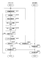
- FIG. 12 is a flowchart showing a processing procedure when automatically adjusting the system settings.
- the control unit 21 of the processor 2 acquires an endoscope image taken by using the first system information from the endoscope 1 (step S201).
- the control unit 21 identifies the part of the subject by using the part identification model 271 that outputs the identification result of identifying the part of the subject when the acquired endoscopic image is input (step S202).
- the control unit 21 Based on the identified site of the subject, the control unit 21 acquires a setting image associated with the site from the setting image DB 276 of the large-capacity storage unit 27 (step S203). The control unit 21 acquires the second system information by using the system information output model 272 that outputs the second system information when the acquired setting image and the identified part of the subject are input (step S204). ..
- the control unit 21 transmits the red intensity, the blue intensity, the brightness setting information, the emphasis mode setting information, the lamp aperture setting information, and the voltage or current to the lamp from the system information DB 273 of the large-capacity storage unit 27. Acquire the first system information including the first system information (step S205). The control unit 21 compares the acquired first system information with the second system information to determine the difference (step S206).
- control unit 21 determines that there is no difference between the first system information and the second system information (NO in step S206).
- the control unit 21 returns to step S201.
- the control unit 21 determines that there is a difference between the first system information and the second system information (YES in step S206)
- the control unit 21 changes the system settings based on the acquired second system information (step S207).
- the control unit 21 determines whether or not the system setting change has been successful (step S208).
- the control unit 21 determines that the system setting change has failed (NO in step S208)
- the control unit 21 outputs a notification including the change failure to the display device 3 (step S209).
- a notification including the change failure is output to the display device 3.
- the control unit 21 returns to step S201.
- the display device 3 displays a notification including the change failure output from the processor 2 (step S301).
- the control unit 21 determines that the system setting change is successful (YES in step S208)
- the control unit 21 outputs a notification including the change success to the display device 3 (step S210).
- the display device 3 displays a notification including the success of the change output from the processor 2 (step S302).
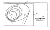
- FIG. 13A and 13B are schematic views of an endoscopic image for displaying a notification on the display device 3.
- Reference numeral 3a is an observation screen (area) of the endoscope.
- 3b is an area for displaying a notification (message).
- the display device 3 displays the endoscopic image output from the processor 2 on 3a, and displays the notification output from the processor 2 on 3b.
- the notification display screen is not limited to the layout described above.
- the notification may be superimposed on the observation screen 3a of the endoscope.
- FIG. 13A shows an example in which when the system setting change is successful, a notification including the fact that the change is successful is displayed.
- the recommended change value (for example, the recommended change value of the strength of red) may be output to the display screen in the system information to be changed.
- FIG. 13B shows an example in which when the system setting change fails, a notification including the change failure is displayed.
- the type of the target system information for which the setting change has failed for example, the strength of red color, etc.
- the changed value used may be output to the display screen.
- ⁇ Modification example 1> When the difference between the first system information and the second system information is equal to or greater than a predetermined threshold value, the process of changing the system settings will be described.
- the control unit 21 of the processor 2 determines the difference between the first system information and the second system information output by the system information output model 272.
- the control unit 21 acquires the threshold value of the difference in system information from the threshold value DB 274 of the large-capacity storage unit 27.
- the control unit 21 determines whether or not the difference between the first system information and the second system information is equal to or greater than the threshold value based on the acquired difference threshold value.
- the control unit 21 determines that the difference between the first system information and the second system information is equal to or greater than the threshold value, the control unit 21 changes the system settings using the second system information.
- the strength of the red color of the first system information is set to "-2" and the strength of the red color of the second system information is determined to be "2".
- the control unit 21 determines that the difference (“4”) between the first system information and the second system information is equal to or greater than a predetermined threshold value (for example, “3”), the control unit 21 determines that the red color of the system is based on the second system information. Change the strength setting of to "2".
- FIG. 14 is a flowchart showing a processing procedure when automatically adjusting the system setting according to the threshold value.
- the contents overlapping with FIG. 12 are designated by the same reference numerals and the description thereof will be omitted.
- the control unit 21 of the processor 2 acquires the threshold value of the difference in system information from the threshold value DB 274 of the large-capacity storage unit 27 (step S221).
- step S222 determines whether or not the difference between the first system information and the second system information is equal to or greater than the threshold value. ). When the control unit 21 determines that the difference between the first system information and the second system information is not equal to or greater than the threshold value (NO in step S222), the control unit 21 returns to step S201. When it is determined that the difference between the first system information and the second system information is equal to or greater than the threshold value (YES in step S222), step S207 is executed.
- this modification it is determined whether or not to automatically adjust the system settings based on the threshold value. If the difference is greater than or equal to the threshold value, the system settings are automatically adjusted, and conversely, if the difference is less than or equal to the threshold value, the system settings are not automatically adjusted. As a result, since there is elasticity that allows fluctuations in a certain range, it is possible to set an appropriate determination rule.
- the second embodiment relates to an embodiment in which system settings are automatically adjusted according to parameters calculated based on an image.
- the description of the contents overlapping with the first embodiment will be omitted.
- the control unit 21 of the processor 2 acquires an endoscope image taken by using the first system information from the endoscope 1.
- the control unit 21 calculates the first parameter based on the acquired endoscopic image.
- the first parameter includes a color tone parameter, a brightness parameter, a spatial frequency parameter, or a noise amount parameter of the endoscopic image.
- the color tone parameter may be, for example, a value obtained by averaging the pixel values of R, G, or B of each pixel constituting the endoscopic image within the entire screen or a predetermined range in the screen, or the pixel value in the image. It may be the frequency of occurrence of pixel values based on a histogram showing the overall distribution of. R is red, G is green, and B is the pixel value of the blue sub-pixel.
- the luminance parameter may be, for example, the luminance in each pixel, that is, ((R + G + B) / 3), or the number of pixels corresponding to each luminance value based on the luminance histogram showing the luminance distribution of the pixels in the image. And the degree of bias of the distribution may be used.
- the spatial frequency parameter may be, for example, the frequency distribution of the image data obtained by the Fourier transform.
- Spatial frequency represents the number of repetitions of the pattern included in the unit length.
- the spatial frequency represents the number of repetitions of sinusoidal shading changes per unit length for a two-dimensional image. In this case, the spatial frequency becomes high at a place where the light and shade changes rapidly, and becomes low at a place where the light and shade changes slowly.
- the noise amount parameter is the amount of image noise and is represented by the standard deviation (SD: Standard Deviation), which is the square root of the variance.
- SD Standard Deviation
- the image noise is a high-frequency component having a high spatial frequency among the non-uniform brightness generated in the captured image.
- the standard deviation is represented by a value that indicates how the data is scattered.
- the control unit 21 acquires the model information of the endoscope 1.
- the model information includes the series and model number of the endoscope, the number of pixels of the image sensor, the target site information (for example, the upper gastrointestinal tract), and the like.
- the control unit 21 acquires model information from the endoscope 1 (scope).
- the control unit 21 acquires the model number from the endoscope 1.
- the control unit 21 may acquire model information corresponding to the acquired model number from the storage unit 22.
- the control unit 21 uses a site identification model 271 that outputs an identification result that identifies the site of the subject when the first parameter calculated based on the endoscopic image and the acquired model information are input. Identify the site of the specimen. The site identification process will be described later.
- the control unit 21 acquires a setting image associated with the identified part of the subject. Since the process of acquiring the set image is the same as that of the first embodiment, the description thereof will be omitted.
- the control unit 21 calculates the second parameter based on the acquired set image. Since the various parameters included in the second parameter are the same as the various parameters included in the first parameter, the description thereof will be omitted.
- the control unit 21 uses a system information output model 272 that outputs the second system information when the second parameter calculated based on the set image and the acquired model information and the identified part of the subject are input. Acquire the second system information.
- the second system information acquisition process will be described later.
- the determination of the difference from the first system information and the system setting change process are the same as those in the first embodiment, and thus the description thereof will be omitted.
- FIG. 15 is an explanatory diagram illustrating the site identification model 271 of the second embodiment.
- the site identification model 271 of the present embodiment has constructed (generated) a neural network that inputs parameters calculated based on an endoscopic image and model information and outputs the result of predicting the site of a subject. It is a classifier.
- the neural network is, for example, CNN, and has an input layer that accepts inputs of parameters and model information calculated based on an endoscopic image, an output layer that outputs a result of predicting a part of a subject, and backpropagation. It has an intermediate layer that has been trained by. Each layer has one or more neurons (nodes), and each neuron has a value. Then, neurons between one layer and the next layer are connected by edges, and each edge has variables (or parameters) such as weights and biases.
- the value of the neuron in each layer is obtained by executing a predetermined operation based on the value of the neuron in the previous layer and the weight of the edge. Then, when the input data is input to the neurons of the input layer, the values of the neurons of the next layer are obtained by a predetermined calculation, and further, the values of the neurons of the next layer are obtained by using the data obtained by the calculation as an input. It is obtained by a predetermined calculation of the layer. Then, the value of the neuron in the output layer, which is the final layer, becomes the output data with respect to the input data.
- the control unit 21 compares the identification result output from the output layer with the labeled information of the part with respect to the teacher data, that is, the correct answer value, and the intermediate layer so that the output value from the output layer approaches the correct answer value. Optimize the variables used for arithmetic processing in.
- the teacher data is data generated by associating the name of the part (for example, the large intestine) with the parameters calculated based on the endoscope image and the model information of the endoscope 1.
- the control unit 21 performs the above processing on the parameters and model information included in the teacher data, and generates the site identification model 271.
- the control unit 21 When the control unit 21 acquires an endoscope image from the endoscope 1, the control unit 21 calculates a parameter based on the acquired endoscope image.
- the control unit 21 identifies the site of the subject using the site identification model 271 based on the calculated parameters.
- the input layer of the site identification model 271 accepts inputs of the parameters "x1 to xn" calculated based on the endoscopic image and the model information "x (n + 1)".
- x1 to xn indicate the color tone parameter, the luminance parameter, the spatial frequency parameter, or the noise amount parameter of the endoscopic image described above.
- x (n + 1) indicates model information including the endoscope series, model number, number of pixels of the image sensor, or target site information.
- the average value of each pixel value of R, G or B of each pixel constituting the endoscopic image, the degree of bias of the distribution based on the histogram, or the spatial frequency is input to the part identification model 271. If this is the case, it will have a great effect on the identification result of the site of the subject.
- the intermediate layer extracts the features of the input information by changing the number of dimensions of the input information input from the input layer.
- the intermediate layer is then predicted to be at each site of the subject according to the extracted features by the fully connected layer whose parameters have been learned by backpropagation.
- the prediction result is output to the output layer having a plurality of neurons. As shown, the probability value in the mouth is 0.02, the probability value in the esophagus is 0.03, the probability value in the stomach is 0.02, the probability value in the small intestine is 0.03, and The prediction result that the probability value of the large intestine is 0.9 is output.
- FIG. 16 is an explanatory diagram illustrating the system information output model 272 of the second embodiment.
- the system information output model 272 predicts the second system information by inputting the parameters calculated based on the set image and the model information and the part of the subject (part identification result) output from the part identification model 271.
- This is an output device for which a neural network has been constructed (generated) that outputs the resulting result.
- the neural network is CNN
- the control unit 21 compares the prediction result output from the output layer with the labeled information of each item of the system information, that is, the correct answer value with respect to the teacher data, so that the output value from the output layer approaches the correct answer value.
- the variables used for arithmetic processing in the intermediate layer are optimized.
- the teacher data is data generated by associating each item of system information with the parameters calculated based on the set image, the model information of the endoscope 1, and the part of the subject.
- the control unit 21 performs the above processing on the parameters and various information included in the teacher data, and generates the system information output model 272.
- the control unit 21 acquires the part of the subject using the site identification model 271
- the control unit 21 acquires a setting image associated with the acquired part of the subject.
- the control unit 21 calculates the parameters based on the acquired setting image.
- the control unit 21 acquires the second system information using the system information output model 272 based on the calculated parameters.
- the input layer of the system information output model 272 is the parameter "y1 to yn" calculated based on the set image, the model information "x (n + 1)", and the subject output from the site identification model 271. Accepts the input of the part "x (n + 2)" of.
- Y1 to yn indicate the color tone parameter, the luminance parameter, the spatial frequency parameter, or the noise amount parameter of the above-mentioned set image.
- x (n + 1) indicates model information including the endoscope series, model number, number of pixels of the image sensor, or target site information.
- x (n + 2) indicates the site of the subject (for example, the large intestine).
- the output result of the second system information is Has a great impact.
- the intermediate layer extracts the features of the input information by changing the number of dimensions of the input information input from the input layer. After that, the intermediate layer predicts the probability of each item of the second system information according to the extracted features by the fully connected layer whose parameters are learned by backpropagation. The prediction result is output to the output layer having a plurality of neurons.
- FIG. 17 is a flowchart showing a processing procedure when automatically adjusting the system setting of the second embodiment.
- the contents overlapping with FIG. 12 are designated by the same reference numerals and the description thereof will be omitted.
- the control unit 21 of the processor 2 calculates the first parameter based on the acquired endoscopic image (step S231).
- the control unit 21 acquires model information including the endoscope series, model number, number of pixels of the image sensor, target site information, etc. stored in the endoscope 1 in advance (step S232). After executing steps S202 to 203, the control unit 21 calculates the second parameter based on the acquired setting image (step S233). The control unit 21 executes step S204.
- the third embodiment relates to a mode in which a set image is stored in association with site information.
- the description of the contents overlapping with the first and second embodiments will be omitted.
- the endoscopic image of the subject taken for each part can be stored in the large-capacity storage unit 27 as a set image.
- FIG. 18 is a flowchart showing a processing procedure when storing the set image.
- the control unit 21 of the processor 2 accepts the selection of an endoscopic image in which the part of the subject is photographed (step S241).
- the control unit 21 stores the received endoscopic image in the large-capacity storage unit 27 in association with the site ID (step S242). Specifically, the control unit 21 allocates the set image ID, associates the set image ID with the set image ID, and stores the set image as one record in the set image DB 276.
- the control unit 21 stores the site ID and the set image ID as one record in the subject DB 275.
- the fourth embodiment relates to an embodiment in which the information processing apparatus 4 automatically adjusts system settings by using artificial intelligence.
- the description of the contents overlapping with the first to third embodiments will be omitted.
- the part identification process and the second system information output process are performed by the processor 2 using the learning model, but in the present embodiment, the above-described process is performed by the information processing device 4. ..
- the information processing device 4 is an information processing device that constructs a learning model, outputs system information using the learning model, processes various information, stores, and transmits / receives.
- the information processing device 4 is, for example, a server device, a personal computer, a general-purpose tablet PC (personal computer), or the like.
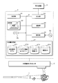
- FIG. 19 is a schematic view showing a configuration example of the endoscope system of the fourth embodiment.
- the contents overlapping with FIGS. 1 and 3 are designated by the same reference numerals and the description thereof will be omitted.
- the system shown in FIG. 19 includes an endoscope 1, a processor 2, a display device 3, and an information processing device 4. Each device transmits and receives electric signals, video signals, etc. via a connector.
- the processor 2 is captured by using the first system information set by the endoscope system in use, the model information of the endoscope stored in the endoscope 1 in advance, and the first system information. Acquire an endoscopic image.
- the processor 2 outputs the acquired first system information, model information, and endoscopic image to the information processing device 4.
- the control unit 21 of the information processing device 4 identifies the part of the subject by using the part identification model 271 that outputs the identification result of identifying the part of the subject when the endoscopic image and the model information are input. .. Since the site identification process is the same as that of the first or second embodiment, the description thereof will be omitted.
- the control unit 21 acquires a setting image associated with the identified site of the subject. Since the process of acquiring the set image is the same as that of the first or second embodiment, the description thereof will be omitted.
- the control unit 21 uses the system information output model 272 that outputs the second system information when the acquired setting image and the model information and the part of the subject identified by the part identification model 271 are input to the second system. Get information. Since the second system information acquisition process is the same as that of the first or second embodiment, the description thereof will be omitted.
- the control unit 21 acquires the first system information from the system information DB 273 of the large-capacity storage unit 27.
- the control unit 21 compares the acquired first system information with the second system information to determine the difference.
- the control unit 21 determines that the two do not match, the control unit 21 outputs a notification of the system setting change and the second system information to the processor 2.
- the processor 2 changes the system settings by using the second system information output from the information processing device 4 in response to the notification of the system setting change output from the information processing device 4.
- the processor 2 outputs the result (for example, success or failure) of the system setting change to the information processing device 4.
- the control unit 21 of the information processing device 4 outputs a notification to the display device 3 according to the result of the setting change output from the processor 2.
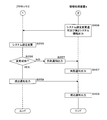
- the 20 and 21 are flowcharts showing a processing procedure when the information processing apparatus 4 automatically adjusts the system settings.
- the processor 2 acquires the first system information stored in the endoscope system in use (step S251).
- the control unit 21 acquires the model information of the endoscope stored in the endoscope 1 in advance (step S252).
- the processor 2 acquires an endoscope image taken by using the first system information from the endoscope 1 (step S253).
- the processor 2 outputs the acquired first system information, model information, and endoscopic image to the information processing device 4 (step S254).
- the processor 2 returns to step S251.
- the control unit 21 of the information processing device 4 stores the first system information output from the processor 2 in the system information DB 273 of the large-capacity storage unit 27 (step S451).
- the processor 2 outputs the first system information and the model information to the information processing device 4, but the present invention is not limited to this.
- the first system information and the model information may be stored in advance in the storage unit 22 or the large-capacity storage unit 27 of the information processing device 4.
- the control unit 21 of the information processing device 4 identifies the part of the subject by using the part identification model 271 that outputs the identification result of identifying the part of the subject when the endoscopic image and the model information are input. (Step S452).
- the control unit 21 acquires a setting image associated with the identified site of the subject (step S453).
- the control unit 21 uses the system information output model 272 that outputs the second system information when the acquired setting image and the model information and the part of the subject identified by the part identification model 271 are input to the second system. Acquire information (step S454).
- the control unit 21 compares each item of the first system information with each item of the corresponding second system information and determines the difference (step S455). When the control unit 21 determines that there is no difference between the first system information and the second system information (NO in step S455), the control unit 21 returns to step S451. When the control unit 21 determines that there is a difference between the first system information and the second system information (YES in step S455), the control unit 21 outputs a notification of the system setting change and the second system information to the processor 2 (step S456). ..
- the processor 2 changes the system settings using the second system information output from the information processing device 4 in response to the notification of the system setting change output from the information processing device 4 (step S255).
- the processor 2 determines whether or not the system setting change is successful (step S256).
- the processor 2 determines that the system setting change has not been successful (NO in step S256)
- the processor 2 outputs a notification of the change failure to the information processing device 4 (step S257).
- the control unit 21 of the information processing device 4 outputs a change failure notification output from the processor 2 to the display device 3 (step S457).
- the processor 2 determines that the system setting change has been successful (YES in step S256)
- the processor 2 outputs a notification of the change success to the information processing device 4 (step S258).
- the control unit 21 of the information processing device 4 outputs the change success notification output from the processor 2 to the display device 3 (step S458).
- FIG. 22 is a functional block diagram showing the operation of the processors 2 of the first to third embodiments.
- the processor 2 executes the control program 2P, the processor 2 operates as follows.
- the functional block diagram showing the operation is similarly applied to the information processing device 4 of the fourth embodiment.
- the image acquisition unit 20a acquires an endoscopic image taken using the first system information.
- the first learning model 20b outputs an identification result that identifies the site of the subject when the endoscopic image acquired by the image acquisition unit 20a is input.
- the setting image acquisition unit 20c acquires a setting image associated with the recognition result output by the first learning model 20b.
- the second learning model 20d outputs the second system information when the setting image acquired by the setting image acquisition unit 20c and the identification result output by the first learning model 20b are input.
- the first calculation unit 20e calculates the parameters based on the endoscopic image acquired by the image acquisition unit 20a.
- the second calculation unit 20f calculates the parameters based on the setting image acquired by the setting image acquisition unit 20c.
- the model information acquisition unit 20g acquires the model information of the endoscope.
- the changing unit 20h changes the system settings based on the second system information output by the second learning model 20d.
- the determination unit 20i determines the difference between the second system information output by the second learning model 20d and the first system information.
- the fifth embodiment is as described above, and the others are the same as those of the first to third embodiments. Therefore, the corresponding parts are designated by the same reference numerals and detailed description thereof will be omitted.
Landscapes
- Engineering & Computer Science (AREA)
- Health & Medical Sciences (AREA)
- Life Sciences & Earth Sciences (AREA)
- Medical Informatics (AREA)
- Physics & Mathematics (AREA)
- General Health & Medical Sciences (AREA)
- Surgery (AREA)
- Theoretical Computer Science (AREA)
- Public Health (AREA)
- Nuclear Medicine, Radiotherapy & Molecular Imaging (AREA)
- Biomedical Technology (AREA)
- Radiology & Medical Imaging (AREA)
- Computer Vision & Pattern Recognition (AREA)
- General Physics & Mathematics (AREA)
- Molecular Biology (AREA)
- Heart & Thoracic Surgery (AREA)
- Pathology (AREA)
- Animal Behavior & Ethology (AREA)
- Optics & Photonics (AREA)
- Biophysics (AREA)
- Veterinary Medicine (AREA)
- Evolutionary Computation (AREA)
- Artificial Intelligence (AREA)
- Signal Processing (AREA)
- Business, Economics & Management (AREA)
- Epidemiology (AREA)
- Primary Health Care (AREA)
- General Business, Economics & Management (AREA)
- Software Systems (AREA)
- Databases & Information Systems (AREA)
- Multimedia (AREA)
- Computing Systems (AREA)
- Quality & Reliability (AREA)
- Endoscopes (AREA)
- Instruments For Viewing The Inside Of Hollow Bodies (AREA)
Priority Applications (5)
| Application Number | Priority Date | Filing Date | Title |
|---|---|---|---|
| ES19941931T ES3056992T3 (en) | 2019-08-16 | 2019-08-16 | Processor for endoscope, endoscope system, information processing device, program, and information processing method |
| EP19941931.8A EP4014832B1 (en) | 2019-08-16 | 2019-08-16 | Processor for endoscope, endoscope system, information processing device, program, and information processing method |
| US17/634,394 US12169948B2 (en) | 2019-08-16 | 2019-08-16 | Processor for endoscope, endoscope system, information processing apparatus, non-transitory computer-readable storage medium, and information processing method |
| PCT/JP2019/032131 WO2021033215A1 (ja) | 2019-08-16 | 2019-08-16 | 内視鏡用プロセッサ、内視鏡システム、情報処理装置、プログラム及び情報処理方法 |
| JP2021541339A JP7162744B2 (ja) | 2019-08-16 | 2019-08-16 | 内視鏡用プロセッサ、内視鏡システム、情報処理装置、プログラム及び情報処理方法 |
Applications Claiming Priority (1)
| Application Number | Priority Date | Filing Date | Title |
|---|---|---|---|
| PCT/JP2019/032131 WO2021033215A1 (ja) | 2019-08-16 | 2019-08-16 | 内視鏡用プロセッサ、内視鏡システム、情報処理装置、プログラム及び情報処理方法 |
Publications (1)
| Publication Number | Publication Date |
|---|---|
| WO2021033215A1 true WO2021033215A1 (ja) | 2021-02-25 |
Family
ID=74659864
Family Applications (1)
| Application Number | Title | Priority Date | Filing Date |
|---|---|---|---|
| PCT/JP2019/032131 Ceased WO2021033215A1 (ja) | 2019-08-16 | 2019-08-16 | 内視鏡用プロセッサ、内視鏡システム、情報処理装置、プログラム及び情報処理方法 |
Country Status (5)
| Country | Link |
|---|---|
| US (1) | US12169948B2 (https=) |
| EP (1) | EP4014832B1 (https=) |
| JP (1) | JP7162744B2 (https=) |
| ES (1) | ES3056992T3 (https=) |
| WO (1) | WO2021033215A1 (https=) |
Cited By (1)
| Publication number | Priority date | Publication date | Assignee | Title |
|---|---|---|---|---|
| JP2023106327A (ja) * | 2022-01-20 | 2023-08-01 | 株式会社Aiメディカルサービス | 検査支援装置、検査支援方法および検査支援プログラム |
Families Citing this family (1)
| Publication number | Priority date | Publication date | Assignee | Title |
|---|---|---|---|---|
| JP7327077B2 (ja) * | 2019-10-18 | 2023-08-16 | トヨタ自動車株式会社 | 路上障害物検知装置、路上障害物検知方法、及び路上障害物検知プログラム |
Citations (11)
| Publication number | Priority date | Publication date | Assignee | Title |
|---|---|---|---|---|
| JP2006288612A (ja) * | 2005-04-08 | 2006-10-26 | Olympus Corp | 画像表示装置 |
| JP2011255038A (ja) * | 2010-06-10 | 2011-12-22 | Hoya Corp | 電子内視鏡装置 |
| JP2013056001A (ja) * | 2011-09-07 | 2013-03-28 | Olympus Corp | 蛍光観察装置 |
| JP2014036738A (ja) * | 2012-08-15 | 2014-02-27 | Hoya Corp | 内視鏡システム |
| JP2015159957A (ja) * | 2014-02-27 | 2015-09-07 | 富士フイルム株式会社 | 内視鏡システム及びその作動方法 |
| JP2016158682A (ja) | 2015-02-27 | 2016-09-05 | Hoya株式会社 | 画像処理装置 |
| JP2016220946A (ja) * | 2015-05-29 | 2016-12-28 | オリンパス株式会社 | 内視鏡装置及び内視鏡装置の設定方法 |
| WO2016208016A1 (ja) * | 2015-06-24 | 2016-12-29 | オリンパス株式会社 | 画像処理装置、画像処理方法、及び画像処理プログラム |
| WO2017126425A1 (ja) * | 2016-01-18 | 2017-07-27 | オリンパス株式会社 | 医療用サーバシステム |
| WO2018105063A1 (ja) * | 2016-12-07 | 2018-06-14 | オリンパス株式会社 | 画像処理装置 |
| WO2018159083A1 (ja) * | 2017-03-03 | 2018-09-07 | 富士フイルム株式会社 | 内視鏡システム、プロセッサ装置、及び、内視鏡システムの作動方法 |
Family Cites Families (5)
| Publication number | Priority date | Publication date | Assignee | Title |
|---|---|---|---|---|
| JP6192882B1 (ja) * | 2015-10-08 | 2017-09-06 | オリンパス株式会社 | 内視鏡システム |
| JP6656357B2 (ja) | 2016-04-04 | 2020-03-04 | オリンパス株式会社 | 学習方法、画像認識装置およびプログラム |
| JP6133474B2 (ja) | 2016-06-21 | 2017-05-24 | Hoya株式会社 | 内視鏡システム |
| US10127659B2 (en) | 2016-11-23 | 2018-11-13 | General Electric Company | Deep learning medical systems and methods for image acquisition |
| CN113498323B (zh) * | 2019-02-26 | 2024-08-13 | 富士胶片株式会社 | 医用图像处理装置、处理器装置、内窥镜系统、医用图像处理方法、及记录介质 |
-
2019
- 2019-08-16 EP EP19941931.8A patent/EP4014832B1/en active Active
- 2019-08-16 US US17/634,394 patent/US12169948B2/en active Active
- 2019-08-16 ES ES19941931T patent/ES3056992T3/es active Active
- 2019-08-16 WO PCT/JP2019/032131 patent/WO2021033215A1/ja not_active Ceased
- 2019-08-16 JP JP2021541339A patent/JP7162744B2/ja active Active
Patent Citations (11)
| Publication number | Priority date | Publication date | Assignee | Title |
|---|---|---|---|---|
| JP2006288612A (ja) * | 2005-04-08 | 2006-10-26 | Olympus Corp | 画像表示装置 |
| JP2011255038A (ja) * | 2010-06-10 | 2011-12-22 | Hoya Corp | 電子内視鏡装置 |
| JP2013056001A (ja) * | 2011-09-07 | 2013-03-28 | Olympus Corp | 蛍光観察装置 |
| JP2014036738A (ja) * | 2012-08-15 | 2014-02-27 | Hoya Corp | 内視鏡システム |
| JP2015159957A (ja) * | 2014-02-27 | 2015-09-07 | 富士フイルム株式会社 | 内視鏡システム及びその作動方法 |
| JP2016158682A (ja) | 2015-02-27 | 2016-09-05 | Hoya株式会社 | 画像処理装置 |
| JP2016220946A (ja) * | 2015-05-29 | 2016-12-28 | オリンパス株式会社 | 内視鏡装置及び内視鏡装置の設定方法 |
| WO2016208016A1 (ja) * | 2015-06-24 | 2016-12-29 | オリンパス株式会社 | 画像処理装置、画像処理方法、及び画像処理プログラム |
| WO2017126425A1 (ja) * | 2016-01-18 | 2017-07-27 | オリンパス株式会社 | 医療用サーバシステム |
| WO2018105063A1 (ja) * | 2016-12-07 | 2018-06-14 | オリンパス株式会社 | 画像処理装置 |
| WO2018159083A1 (ja) * | 2017-03-03 | 2018-09-07 | 富士フイルム株式会社 | 内視鏡システム、プロセッサ装置、及び、内視鏡システムの作動方法 |
Cited By (1)
| Publication number | Priority date | Publication date | Assignee | Title |
|---|---|---|---|---|
| JP2023106327A (ja) * | 2022-01-20 | 2023-08-01 | 株式会社Aiメディカルサービス | 検査支援装置、検査支援方法および検査支援プログラム |
Also Published As
| Publication number | Publication date |
|---|---|
| US12169948B2 (en) | 2024-12-17 |
| EP4014832C0 (en) | 2025-12-17 |
| EP4014832A4 (en) | 2023-04-26 |
| US20220327738A1 (en) | 2022-10-13 |
| ES3056992T3 (en) | 2026-02-25 |
| EP4014832A1 (en) | 2022-06-22 |
| JP7162744B2 (ja) | 2022-10-28 |
| EP4014832B1 (en) | 2025-12-17 |
| JPWO2021033215A1 (https=) | 2021-02-25 |
Similar Documents
| Publication | Publication Date | Title |
|---|---|---|
| JP6952214B2 (ja) | 内視鏡用プロセッサ、情報処理装置、内視鏡システム、プログラム及び情報処理方法 | |
| US12169963B2 (en) | Processing system, image processing method, learning method, and processing device | |
| US11944262B2 (en) | Endoscope processor, information processing device, and endoscope system | |
| US12417531B2 (en) | Image processing system, training method for training device, and storage medium | |
| WO2022049901A1 (ja) | 学習装置、学習方法、画像処理装置、内視鏡システム及びプログラム | |
| EP4231314A1 (en) | Surgery support system, surgery support method, information processing apparatus, and information processing program | |
| JP7429715B2 (ja) | 画像処理システム、内視鏡システム、画像処理システムの作動方法及びプログラム | |
| KR102637484B1 (ko) | 인공지능 기반의 내시경 진단 보조 시스템 및 이의 제어방법 | |
| WO2021229684A1 (ja) | 画像処理システム、内視鏡システム、画像処理方法及び学習方法 | |
| EP4014831B1 (en) | Processor for endoscope, endoscope system, information processing device, program, and information processing method | |
| US20190122344A1 (en) | Image processing apparatus, image processing method, and non-transitory computer readable recording medium | |
| EP4014832B1 (en) | Processor for endoscope, endoscope system, information processing device, program, and information processing method | |
| JP2021037356A (ja) | 内視鏡用プロセッサ、情報処理装置、内視鏡システム、プログラム及び情報処理方法 | |
| US20250194910A1 (en) | Endoscope control device, method of changing wavelength characteristics of illumination light, and information storage medium | |
| US12620211B2 (en) | Processing system, image processing method, learning method, and processing device | |
| WO2024004013A1 (ja) | プログラム、情報処理方法、及び情報処理装置 | |
| KR20250152725A (ko) | 인공지능 기반 내시경 병변 통합 탐지 시스템 | |
| WO2024084838A1 (ja) | 画像処理装置、画像処理方法及び記憶媒体 | |
| WO2026094167A1 (ja) | 制御装置、内視鏡システム及び処理方法 | |
| WO2024180796A1 (ja) | 画像処理装置、画像処理方法及び記憶媒体 |
Legal Events
| Date | Code | Title | Description |
|---|---|---|---|
| 121 | Ep: the epo has been informed by wipo that ep was designated in this application |
Ref document number: 19941931 Country of ref document: EP Kind code of ref document: A1 |
|
| ENP | Entry into the national phase |
Ref document number: 2021541339 Country of ref document: JP Kind code of ref document: A |
|
| NENP | Non-entry into the national phase |
Ref country code: DE |
|
| ENP | Entry into the national phase |
Ref document number: 2019941931 Country of ref document: EP Effective date: 20220316 |
|
| WWG | Wipo information: grant in national office |
Ref document number: 2019941931 Country of ref document: EP |