WO2021029382A1 - Ue et smf - Google Patents
Ue et smf Download PDFInfo
- Publication number
- WO2021029382A1 WO2021029382A1 PCT/JP2020/030441 JP2020030441W WO2021029382A1 WO 2021029382 A1 WO2021029382 A1 WO 2021029382A1 JP 2020030441 W JP2020030441 W JP 2020030441W WO 2021029382 A1 WO2021029382 A1 WO 2021029382A1
- Authority
- WO
- WIPO (PCT)
- Prior art keywords
- pdu session
- information
- session
- smf
- 3gpp access
- Prior art date
Links
Images

Classifications
-
- H—ELECTRICITY
- H04—ELECTRIC COMMUNICATION TECHNIQUE
- H04W—WIRELESS COMMUNICATION NETWORKS
- H04W76/00—Connection management
- H04W76/10—Connection setup
- H04W76/12—Setup of transport tunnels
-
- H—ELECTRICITY
- H04—ELECTRIC COMMUNICATION TECHNIQUE
- H04W—WIRELESS COMMUNICATION NETWORKS
- H04W28/00—Network traffic management; Network resource management
- H04W28/02—Traffic management, e.g. flow control or congestion control
- H04W28/08—Load balancing or load distribution
- H04W28/09—Management thereof
- H04W28/0925—Management thereof using policies
-
- H—ELECTRICITY
- H04—ELECTRIC COMMUNICATION TECHNIQUE
- H04W—WIRELESS COMMUNICATION NETWORKS
- H04W8/00—Network data management
- H04W8/02—Processing of mobility data, e.g. registration information at HLR [Home Location Register] or VLR [Visitor Location Register]; Transfer of mobility data, e.g. between HLR, VLR or external networks
- H04W8/08—Mobility data transfer
- H04W8/14—Mobility data transfer between corresponding nodes
-
- H—ELECTRICITY
- H04—ELECTRIC COMMUNICATION TECHNIQUE
- H04W—WIRELESS COMMUNICATION NETWORKS
- H04W48/00—Access restriction; Network selection; Access point selection
- H04W48/18—Selecting a network or a communication service
-
- H—ELECTRICITY
- H04—ELECTRIC COMMUNICATION TECHNIQUE
- H04W—WIRELESS COMMUNICATION NETWORKS
- H04W76/00—Connection management
- H04W76/10—Connection setup
-
- H—ELECTRICITY
- H04—ELECTRIC COMMUNICATION TECHNIQUE
- H04W—WIRELESS COMMUNICATION NETWORKS
- H04W76/00—Connection management
- H04W76/10—Connection setup
- H04W76/15—Setup of multiple wireless link connections
-
- H—ELECTRICITY
- H04—ELECTRIC COMMUNICATION TECHNIQUE
- H04W—WIRELESS COMMUNICATION NETWORKS
- H04W76/00—Connection management
- H04W76/30—Connection release
-
- H—ELECTRICITY
- H04—ELECTRIC COMMUNICATION TECHNIQUE
- H04W—WIRELESS COMMUNICATION NETWORKS
- H04W28/00—Network traffic management; Network resource management
- H04W28/02—Traffic management, e.g. flow control or congestion control
- H04W28/0252—Traffic management, e.g. flow control or congestion control per individual bearer or channel
-
- H—ELECTRICITY
- H04—ELECTRIC COMMUNICATION TECHNIQUE
- H04W—WIRELESS COMMUNICATION NETWORKS
- H04W76/00—Connection management
- H04W76/10—Connection setup
- H04W76/11—Allocation or use of connection identifiers
-
- H—ELECTRICITY
- H04—ELECTRIC COMMUNICATION TECHNIQUE
- H04W—WIRELESS COMMUNICATION NETWORKS
- H04W76/00—Connection management
- H04W76/10—Connection setup
- H04W76/15—Setup of multiple wireless link connections
- H04W76/16—Involving different core network technologies, e.g. a packet-switched [PS] bearer in combination with a circuit-switched [CS] bearer
-
- H—ELECTRICITY
- H04—ELECTRIC COMMUNICATION TECHNIQUE
- H04W—WIRELESS COMMUNICATION NETWORKS
- H04W76/00—Connection management
- H04W76/30—Connection release
- H04W76/32—Release of transport tunnels
-
- H—ELECTRICITY
- H04—ELECTRIC COMMUNICATION TECHNIQUE
- H04W—WIRELESS COMMUNICATION NETWORKS
- H04W76/00—Connection management
- H04W76/30—Connection release
- H04W76/34—Selective release of ongoing connections
Definitions
- the 3GPP (3rd Generation Partnership Project) is studying the system architecture of 5GS (5G System), which is a 5th generation (5G) mobile communication system, and discussions are being held to support new procedures and new functions.
- 5GS 5G System
- 5GC 5G Core Network
- ATSSS Access Traffic Steering, Switching and Splitting
- 5GS Non-Patent Document 1, Non-Patent Document 2).
- Non-Patent Document 3 Non-Patent Document 3
- ATSSS In the discussion on ATSSS, it is not the PDU (Protocol Data Unit) session (also called single access PDU session, SA PDU session, SA PDU Session) that has already been defined, but the multi-access PDU session (MA PDU session, MA PDU Session). Communication using a special PDU session called) is under consideration and discussion.
- PDU Protocol Data Unit
- PDU session anchor also called PDU Session Anchor, PSA
- PSA PDU Session Anchor
- SSC Session and Service Continuity
- SSC Session and Service Continuity
- One aspect of the present invention has been made in view of the above circumstances, and an object thereof is a procedure for changing the PSA of an MA PDU session in which SSC mode 2 or SSC mode 3 is set, or a MA PDU.
- the purpose is to clarify the behavior.
- the UE of one embodiment of the present invention is a UE (User Equipment) including a control unit and a transmission / reception unit, and the transmission / reception unit is from an AMF (Access and Mobility Management Function) and the network is ATSSS (Access Traffic Steering, Upon receiving the first information indicating whether or not to support Switching, Splitting), the control unit identifies whether or not ATSSS is supported by the network based on the first information, and the above-mentioned If the network does not support ATSSS, the control unit does not start the PDU session establishment procedure in order to establish an MA (Multi-Access) PDU (Protocol Data Unit) session.
- MA Multi-Access
- PDU Protocol Data Unit
- the communication control method is a communication control method executed by a UE (User Equipment), and the UE is from AMF (Access and Mobility Management Function) and the network is ATSSS (Access Traffic). It receives a first piece of information indicating whether it supports Steering, Switching, Splitting), and based on the first piece of information, identifies whether ATSSS is supported by the network, and the network is ATSSS. If the above is not supported, the PDU session establishment procedure is not started in order to establish the MA (Multi-Access) PDU (Protocol Data Unit) session.
- MA Multi-Access
- PDU Protocol Data Unit
- a procedure for changing the PSA of the MA PDU session in which SSC mode 2 or SSC mode 3 is set or a procedure for changing a part of the PSA of the MA PDU session to the PSA of the SA PDU session. It is also possible to clarify the procedure for changing a part of the PSA of the SA PDU session to the PSA of the MA PDU session and the behavior of each device when those procedures are executed.
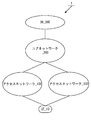
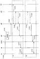
- FIG. 1 is a diagram for explaining the outline of the mobile communication system 1
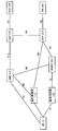
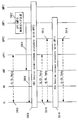
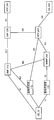
- FIG. 2 is a diagram for explaining the detailed configuration of the mobile communication system 1 and the first communication state.
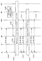
- FIG. 14 is a diagram for explaining a second communication state.
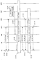
- FIG. 15 is a diagram for explaining a third communication state.
- FIG. 1 shows that the mobile communication system 1 is composed of UE (User Equipment) _10, access network _100, access network _102, core network _200, and DN (Data Network) _300.
- UE User Equipment
- DN Data Network
- these devices / networks may be described by omitting symbols such as UE, access network, core network, DN and the like.
- Fig. 2 shows UE_10, base station device_110, base station device_120, AMF (Access and Mobility Management Function) _210, SMF (Session Management Function) _220, UPF (User Plane Function) _230, N3IWF (Non). -3GPP InterWorking Function) _240, PCF (Policy Control Function) _250, DN_300 and other device / network functions, and interfaces for connecting these devices / network functions to each other are described.
- AMF Access and Mobility Management Function
- SMF Session Management Function
- UPF User Plane Function
- N3IWF Non
- PCF Policy Control Function
- devices / network functions such as UE_10, base station device_112, base station device_122, AMF_210, SMF_220, UPF_232, N3IWF_242, PCF_250, DN_300, and these devices / network functions are connected to each other.
- the interface is described.
- devices / network functions such as UE_10, base station device_110, base station device_122, AMF_210, SMF_220, UPF_230, UPF_232, N3IWF_242, PCF_250, DN_300, and these devices / network functions are shown to each other.
- the interface to connect is described. Note that these devices / network functions may be described by omitting symbols such as UE, base station device, AMF, SMF, UPF, N3IWF, PCF, DN, etc.
- 5GS which is a 5G system, is configured to include a UE, an access network, and a core network, but may further include a DN.
- the UE is a device that can connect to network services via 3GPP access (3GPP access network, also called 3GPP AN) and / or non-3GPP access (non-3GPP access network, also called non-3GPP AN). is there.
- the UE may be a terminal device capable of wireless communication such as a mobile phone or a smartphone, and may be a terminal device capable of connecting to EPS (Evolved Packet System), which is a 4G system, or 5GS.
- EPS Evolved Packet System
- the UE may be provided with UICC (Universal Integrated Circuit Card) or eUICC (Embedded UICC).
- the UE may be expressed as a user device or a terminal device.
- the UE is a device that can use the ATSSS (Access Traffic Steering, Switching and Splitting) function, that is, an ATSSS capable UE.
- ATSSS Access Traffic Steering, Switching and Splitting
- the access network may also be referred to as a 5G access network (5G AN).
- 5GAN is composed of NG-RAN (NG Radio Access Network) and / or non-3GPP access network (non-3GPPAN).
- NG-RAN NG Radio Access Network
- non-3GPPAN non-3GPP access network
- One or more base chrysanthemum devices are installed in NG-RAN.
- the base station device may be gNB.
- gNB is a node that provides the NR (New Radio) user plane and control plane to the UE, and is a node that connects to 5GC via an NG interface (including an N2 interface or an N3 interface). That is, gNB is a newly designed base station device for 5GS and has a different function from the base station device (eNB) used in EPS.
- eNB base station device
- each gNB is connected to each other by, for example, an Xn interface.
- NG-RAN may be referred to as 3GPP access.
- wireless LAN access network and non-3GPP AN may be referred to as non-3GPP access.
- the nodes arranged in the access network may be collectively referred to as NG-RAN nodes.
- the device included in the access network and / or the device included in the access network may be referred to as an access network device.
- access network_100 supports 3GPP access
- access network_102 supports non-3GPP access.
- base station equipment_110 and / or base station equipment_112 is arranged in access network_100
- base station equipment_120 and / or base station equipment_122 and / or TNAP are arranged in access network_102.
- the base station device_110 and / or the base station device_112 and / or the base station device_120 and / or the base station device_122 and / or TNAP may be able to use the ATSSS function.
- access network_102 may be referred to as Untrusted Non-3GPP Access or Trusted Non-3GPP Access.
- the base station device 120 and N3IWF in FIG. 2 describe the case of Untrusted Non-3GPP Access. That is, when the access network_102 is Untrusted Non-3GPP Access, the base station device_120 or the base station device_122 and N3IWF are used.
- the access network_102 is Trusted Non-3GPP Access (also referred to as Trusted Non-3GPP Access Network, TNAN), instead of base station device _120 or base station device _122 and N3IWF, Trusted Non-3GPP Access Point (also called TNAP) and Trusted Non-3GPP Gateway Function (also called TNGF) are used.
- TNAP and TNGF are located on access network _102 or core network _200.
- the core network is compatible with 5GC (5G Core Network).
- 5GC 5G Core Network
- AMF, UPF, SMF, PCF and the like are arranged in 5GC.
- 5GC may be expressed as 5GCN.
- the AMF, UPF, SMF, and PCF may be able to use the ATSSS function.
- N3IWF is located in access network_102 or core network_200.
- the core network and / or the device included in the core network may be referred to as a core network device.
- the core network may be an IP mobile communication network operated by a mobile network operator (MNO) that connects the access network and the DN, or a mobile network operator 1 that operates and manages the mobile communication system 1. It may be a core network for a mobile network operator, or a core network for a virtual mobile network operator such as MVNO (Mobile Virtual Network Operator) or MVNE (Mobile Virtual Network Enabler) or a virtual mobile communication service provider. ..
- MNO mobile network operator
- MVNE Mobile Virtual Network Enabler
- the DN may be a DN that provides a communication service to the UE.
- the DN may be configured as a packet data service network or may be configured for each service.
- the DN may include a connected communication terminal. Therefore, connecting to the DN may be connecting to a communication terminal or server device arranged in the DN. Further, sending and receiving user data to and from the DN may be sending and receiving user data to and from a communication terminal or server device arranged in the DN.
- At least a part of an access network, a core network, a DN, and / or one or more devices included in these may be referred to as a network or a network device. That is, a network and / or network device sending and receiving messages and / or performing a procedure means that an access network, a core network, at least a portion of a DN, and / or one or more devices contained therein. , Sending and receiving messages, and / or performing procedures.
- the UE can connect to the access network.
- the UE can also connect to the core network via the access network.
- the UE can connect to the DN via the access network and the core network. That is, the UE can send / receive (communicate) user data with the DN.
- IP Internet Protocol
- non-IP communication may be used.
- IP communication is data communication using IP, and data is transmitted and received by IP packets.
- An IP packet is composed of an IP header and a payload part.
- the payload section may include devices / functions included in EPS and data transmitted / received by devices / functions included in 5GS.
- non-IP communication is data communication that does not use IP, and data is transmitted and received in a format different from the structure of IP packets.
- non-IP communication may be data communication realized by sending and receiving application data to which an IP header is not added, or a UE can add another header such as a Mac header or an Ethernet (registered trademark) frame header.
- User data to be sent and received may be sent and received.
- each device may be configured as physical hardware, may be configured as logical (virtual) hardware configured on general-purpose hardware, or may be configured as software. May be done. Further, at least a part (including all) of the functions of each device may be configured as physical hardware, logical hardware, or software.
- each storage unit (storage unit_330, storage unit_440, storage unit_540) in each device / function appearing below is, for example, a semiconductor memory, SSD (Solid State Drive), HDD (Hard Disk Drive). ) Etc.
- each storage unit has not only the information originally set from the shipping stage, but also devices / functions other than its own device / function (for example, UE and / or access network device, and / or core network device, and /.
- various information transmitted / received to / from PDN and / or DN can be stored.
- each storage unit can store identification information, control information, flags, parameters, and the like included in control messages transmitted and received in various communication procedures described later. Further, each storage unit may store such information for each UE.
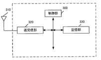
- the UE is composed of a control unit_300, an antenna_310, a transmission / reception unit_320, and a storage unit_330.
- the control unit_300, the transmission / reception unit_320, and the storage unit_330 are connected via a bus.
- the transmitter / receiver_320 is connected to the antenna_310.
- Control unit_300 is a functional unit that controls the operation and functions of the entire UE.
- the control unit_300 may process all the functions that the other functional units (transmission / reception unit_320, storage unit_330) in the UE do not have.
- the control unit _300 realizes various processes in the UE by reading and executing various programs stored in the storage unit _330 as needed.
- the transmission / reception unit_320 is a functional unit for wireless communication with a base station device or the like in the access network via the antenna_310. That is, the UE can transmit / receive user data and / or control information to / from the access network device and / or the core network device and / or the DN by using the transmission / reception unit_320.
- the UE can communicate with the base station device_110, the base station device_120, and TNAP by using the transmission / reception unit_320. That is, the UE communicates with the base station device_110 when communicating via 3GPP access. The UE also communicates with base station device_120 or TNAP when communicating via non-3GPP access. More specifically, the UE communicates with the base station device_120 when communicating via Untrusted non-3GPP Access, and the UE communicates with TNAP when communicating via Trusted non-3GPP Access. .. In this way, the UE can change the connection destination according to the access network to be used.
- the UE can communicate with the core network device (AMF, SMF, UPF, etc.) by using the transmitter / receiver _320.
- AMF core network device
- SMF SMF
- UPF User Plane Function
- the UE can send and receive AMF and NAS (Non-Access-Stratum) messages via the N1 interface (the interface between the UE and AMF).
- the N1 interface is a logical interface
- the communication between the UE and AMF is actually base station device_110, base station device_112, base station device_120, base station device_122, It is done via TNAP.
- the UE may communicate with AMF via base station device_110 or base station device_112 when communicating via 3GPP access.
- non-3GPP access Untrusted non-3GPP Access
- the UE can communicate with the base station device_120 or the base station device_122 via N3IWF with AMF.
- the UE can communicate with AMF via TNAP and TNGF.
- the information exchanged between the UE and AMF is mainly control information.
- the UE can communicate with the SMF using the N1 interface and the N11 interface (the interface between the AMF and the SMF). Specifically, the UE can communicate with the SMF via the AMF. As described above, the communication path between the UE and AMF may follow three types of routes depending on the access (3GPP access, Untrusted Non-3GPP Access, Trusted Non-3GPP Access).
- the information exchanged between the UE and SMF is mainly control information.
- the UE can communicate with the UPF using the N3 interface (the interface between the access network and the UPF). Specifically, the UE may communicate with the UPF via base station device_110 or base station device_112 when communicating via 3GPP access. Further, when communicating via non-3GPP access (Untrusted non-3GPP Access), the UE can communicate with the UPF via base station device_120 or base station device_122 and N3IWF. In addition, the UE can communicate with the UPF via TNAP and TNGF when communicating via non-3GPP access (Trusted non-3GPP Access).
- the communication path between the UE and UPF is mainly used to send and receive user data.
- the UE can communicate with the PCF using the N1 interface, the N11 interface, and the N7 interface (the interface between the SMF and the PCF). Specifically, the UE can communicate with the PCF via AMF and SMF. As described above, the communication path between the UE and AMF may follow three types of routes depending on the access (3GPP access, Untrusted Non-3GPP Access, Trusted Non-3GPP Access). The information exchanged between the UE and the PCF is mainly control information.
- UE can communicate with DN using N3 interface and N6 interface (interface between UPF and DN). Specifically, when communicating via 3GPP access, the UE can communicate with base station device_110 or base station device_112 and DN via UPF. Further, when communicating via non-3GPP access (Untrusted non-3GPP Access), the UE can communicate with the DN via the base station device_120 or the base station device_122, N3IWF, and UPF. In addition, when communicating via non-3GPP access (Trusted non-3GPP Access), the UE can communicate with DN via TNAP, TNGF, and UPF.
- the communication path between the UE and DN that is, the PDU session or MAPDU session, is mainly used to send and receive user data.
- the above only describes the communication between the UE and a typical device / function in the present specification, and the UE can communicate with a device / function other than the above, that is, a core network device other than the above. Needless to say.
- the storage unit_330 is a functional unit for storing programs, user data, control information, etc. required for each operation of the UE.
- the UE is a UE that supports the ATSSS function, and it is desirable that the control information received from the core network side be stored in the storage unit_330. Then, the control unit _300 performs communication using the MA PDU session or performs communication using the SA PDU session according to the control information received from the core network side or the control information stored in the storage unit _330. It may have a function of determining whether or not. Also, when communicating using a MAPDU session, determine whether to communicate via 3GPP access only, non-3GPP access only, or 3GPP access and non-3GPP access. can do. In addition, when communicating using the SA PDU session, it is possible to determine whether to communicate only via 3GPP access or only non-3GPP access. The control unit_300 controls the transmission / reception unit 320 so that it can communicate appropriately according to these decisions.
- the UE when communicating using a MAPDU session, the UE may have a function of deciding which access the uplink traffic should be routed to according to the ATSSS rules received from the SMF.
- the UE may have a function of requesting the establishment of a MA PDU session based on the URSP rules received from the PCF.
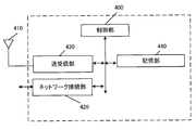
- Base station device_110 is a base station device located in 3GPP access.
- the base station device_110 is composed of a control unit_400, an antenna_410, a network connection unit_420, a transmission / reception unit_430, and a storage unit_440.
- the control unit_400, network connection unit_420, transmission / reception unit_430, and storage unit_440 are connected via a bus.
- the transmitter / receiver_430 is connected to the antenna_410.
- the base station device_110 may be a base station device that supports the ATSSS function.
- Control unit_400 is a functional unit that controls the operation and functions of the entire base station device_110. Note that the control unit_400 may process all the functions that the other functional units (network connection unit_420, transmission / reception unit_430, storage unit_440) in the base station device_110 do not have. The control unit _400 realizes various processes in the base station device _110 by reading and executing various programs stored in the storage unit _440 as needed.
- the network connection unit_420 is a functional unit for the base station device_110 to communicate with the AMF and / or the UPF. That is, the base station apparatus_110 can send and receive control information and / or user data to and from the AMF and / or the UPF or the like by using the network connection unit_420.
- the base station device_110 can communicate with the AMF via the N2 interface (the interface between the access network and the AMF) by using the network connection unit_420. Further, the base station device_110 can communicate with the UPF via the N3 interface by using the network connection unit_420.
- the transmitter / receiver_430 is a functional unit for wireless communication with the UE via the antenna_410. That is, the base station device_110 can transmit / receive user data and / or control information between the UE and the UE by using the transmission / reception unit_430 and the antenna_410.
- the base station device_110 has a function of transmitting user data and / or control information to the core network device when the user data and / or control information addressed to the core network device is received from the UE. Further, the base station apparatus_110 has a function of transmitting the user data and / or the control information to the UE when the user data and / or the control information addressed to the UE is received from the core network apparatus.
- the above only describes the communication between the base station device_110 and a typical device / function, and the base station device_110 communicates with a device / function other than the above, that is, a core network device other than the above. It goes without saying that you can do it.
- the storage unit_440 is a functional unit for storing programs, user data, control information, etc. required for each operation of the base station device_110.
- Base station device_120 is a base station device located in non-3GPP access (Untrusted non-3GPP Access).
- the base station device_120 is composed of a control unit_400, an antenna_410, a network connection unit_420, a transmission / reception unit_430, and a storage unit_440.
- the control unit_400, network connection unit_420, transmission / reception unit_430, and storage unit_440 are connected via a bus.
- the transmitter / receiver_430 is connected to the antenna_410.
- the base station device_120 may be a base station device that supports the ATSSS function.
- Control unit_400 is a functional unit that controls the operation and functions of the entire base station device_120.
- the control unit _400 may process all the functions that the other functional units (network connection unit _420, transmission / reception unit _430, storage unit _440) in the base station device _120 do not have.
- the control unit _400 realizes various processes in the base station apparatus _120 by reading and executing various programs stored in the storage unit _440 as needed.
- the network connection unit_420 is a functional unit for the base station device_120 to communicate with the N3IWF, and is a functional unit for communicating with the AMF and / or UPF via the N3IWF. That is, the base station device_120 can send and receive control information and / or user data to and from the N3IWF by using the network connection unit_420. Further, the base station device_120 can transmit / receive control information and / or user data to / from the AMF and / or the UPF or the like by using the network connection unit_420.
- the base station device_120 can communicate with the N3IWF via the Y2 interface (the interface between the access network and the N3IWF) by using the network connection unit_420.
- the base station device_120 can communicate with the AMF via the N2 interface (the interface between the N3IWF and the AMF) via the N3IWF.
- the base station device_120 can communicate with the UPF via the N3 interface (the interface between the N3IWF and the UPF) via the N3IWF.
- the transmitter / receiver_430 is a functional unit for wireless communication with the UE via the antenna_410. That is, the base station apparatus_120 uses the transmitter / receiver _430 and the antenna_410 to transmit user data and / or control information to and from the UE via the Y1 interface (interface between the access network and the UE). You can send and receive.
- the base station device_120 has a function of transmitting the user data and / or the control information to the core network device when the user data and / or the control information addressed to the core network device is received from the UE. Further, the base station apparatus_120 has a function of transmitting the user data and / or the control information to the UE when the user data and / or the control information addressed to the UE is received from the core network apparatus.
- the base station device_120 only describes the communication between the base station device_120 and a typical device / function, and the base station device_120 communicates with a device / function other than the above, that is, a core network device other than the above. It goes without saying that you can do it.
- the storage unit_440 is a functional unit for storing programs, user data, control information, etc. required for each operation of the base station device_120.
- TNAP is a base station device (also referred to as an access point) located in non-3GPP access (Trusted non-3GPP Access).
- TNAP is composed of a control unit_400, an antenna_410, a network connection unit_420, a transmission / reception unit_430, and a storage unit_440.
- the control unit_400, network connection unit_420, transmission / reception unit_430, and storage unit_440 are connected via a bus.
- the transmitter / receiver_430 is connected to the antenna_410.
- the TNAP may be a TNAP that supports the ATSSS function.
- Control unit_400 is a functional unit that controls the operation and functions of the entire TNAP.
- the control unit_400 may process all the functions that the other functional units (network connection unit_420, transmission / reception unit_430, storage unit_440) in TNAP do not have.
- the control unit _400 realizes various processes in TNAP by reading and executing various programs stored in the storage unit _440 as needed.
- the network connection unit_420 is a functional unit for TNAP to communicate with TNGF, and is a functional unit for communicating with AMF and / or UPF via TNGF. That is, TNAP can send and receive control information and / or user data to and from TNGF using the network connection unit_420. In addition, TNAP can send and receive control information and / or user data to and from AMF and / or UPF, etc. using the network connection unit_420.
- TNAP can communicate with TNGF via the Ta interface (the interface between TNAP and TNGF) by using the network connection part_420.
- TNAP can communicate with AMF via N2 interface (interface between TNGF and AMF) via TNGF.
- TNAP can communicate with UPF via N3 interface (interface between TNGF and UPF) via TNGF.
- the transmitter / receiver_430 is a functional unit for wireless communication with the UE via the antenna_410. That is, TNAP can send and receive user data and / or control information to and from the UE via the Yt interface (interface between TNAP and UE) using the transmitter / receiver _430 and antenna_410. ..
- TNAP has a function of transmitting user data and / or control information to the core network device when receiving user data and / or control information addressed to the core network device from the UE. Further, TNAP has a function of transmitting user data and / or control information to the UE when the user data and / or control information addressed to the UE is received from the core network device.
- TNAP can communicate with a device / function other than the above, that is, a core network device other than the above. ..
- the storage unit_440 is a functional unit for storing programs, user data, control information, etc. required for each operation of TNAP.
- N3IWF is a device and / or function that is placed between non-3GPP access and 5GC when the UE connects to 5GS via non-3GPP access (Untrusted non-3GPP Access). It is located in non-3GPP access (Untrusted non-3GPP Access) or core network.
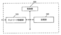
- N3IWF consists of a control unit_500, a network connection unit_520, and a storage unit_540. The control unit_500, network connection unit_520, and storage unit_540 are connected via a bus. Further, the N3IWF may be an N3IWF that supports the ATSSS function.
- Control unit_500 is a functional unit that controls the operation and functions of the entire N3IWF. Note that the control unit_500 may process all the functions that the other functional units (network connection unit_520, storage unit_540) in the N3IWF do not have. The control unit_500 realizes various processes in the N3 IWF by reading and executing various programs stored in the storage unit_540 as needed.
- the network connection unit_520 is a functional unit for N3IWF to communicate with the base station device_120 or the base station device_122, and / or the AMF, and / or the UPF. That is, the N3IWF can send and receive control information and / or user data to and from the base station device _120 or the base station device _122 by using the network connection unit _520. In addition, N3IWF can send and receive control information and / or user data to and from AMF and / or UPF, etc. using the network connection unit_520.
- the N3IWF can communicate with the base station device _120 or the base station device _122 via the Y2 interface by using the network connection unit _520.
- the N3IWF can also communicate with the AMF via the N2 interface.
- N3IWF can also communicate with UPF via the N3 interface.
- the above only describes the communication between the N3IWF and a typical device / function, and it goes without saying that the N3IWF can communicate with a device / function other than the above, that is, a core network device other than the above. ..
- the storage unit_540 is a functional unit for storing programs, user data, control information, etc. required for each operation of N3IWF.
- N3IWF has a function to establish an IPsec tunnel between the UE and an IPsec tunnel, a function to terminate the N2 interface for the control plane, a function to terminate the N3 interface for the user plane, a function to relay NAS signaling between the UE and AMF, and a PDU session.
- Ability to process N2 signaling from SMF with respect to and QoS a function to establish IPsec SA (Security Association) to support PDU session traffic, a function to relay userplane packets between UE and UPF (IPsec) Includes packet encapsulation / decapsulation for N3 tunnels), functions as a local mobility anchor within an untrusted non-3GPP access network, and the ability to select AMF. All of these functions are controlled by control unit_500.
- TNGF is a device and / or function that is placed between non-3GPP access and 5GC when the UE connects to 5GS via non-3GPP access (Trusted non-3GPP Access). It is located in non-3GPP Access (Trusted non-3GPP Access) or in the core network.
- the TNGF is composed of a control unit_500, a network connection unit_520, and a storage unit_540. The control unit_500, network connection unit_520, and storage unit_540 are connected via a bus. Also, the TNGF may be a TNGF that supports the ATSSS function.
- Control unit_500 is a functional unit that controls the operation and functions of the entire TNGF.
- the control unit_500 may process all the functions that the other functional units (network connection unit_520, storage unit_540) in the TNGF do not have.
- the control unit _500 realizes various processes in the TNGF by reading and executing various programs stored in the storage unit _540 as needed.
- Network connection _520 is a functional unit for TNGF to communicate with TNAP and / or AMF and / or UPF. That is, the TNGF can send and receive control information and / or user data to and from TNAP using the network connection unit_520. In addition, the TNGF can send and receive control information and / or user data to and from the AMF and / or the UPF, etc. using the network connection unit_520.
- TNGF can communicate with TNAP via the Y2 interface by using the network connection part_520.
- the TNGF can also communicate with the AMF via the N2 interface.
- TNGF can also communicate with UPF via the N3 interface.
- the above only describes the communication between the TNGF and a typical device / function, and it goes without saying that the TNGF can communicate with a device / function other than the above, that is, a core network device other than the above. ..
- the storage unit_540 is a functional unit for storing programs, user data, control information, etc. required for each operation of TNGF.
- TNGF has a function to terminate N2 interface and N3 interface, a function to act as an approver when UE registers with 5GC via TNAN, a function to select AMF, and a NAS message between UE and AMF.
- the AMF consists of a control unit_500, a network connection unit_520, and a storage unit_540.
- the control unit_500, network connection unit_520, and storage unit_540 are connected via a bus.
- the AMF may be a node that handles the control plane. Further, the AMF may be an AMF that supports the ATSSS function.
- Control unit_500 is a functional unit that controls the operation and functions of the entire AMF.
- the control unit_500 may process all the functions that the other functional units (network connection unit_520, storage unit_540) in the AMF do not have.
- the control unit_500 realizes various processes in AMF by reading and executing various programs stored in the storage unit_540 as needed.
- the network connection part_520 is a functional part for AMF to connect to the base station equipment in 5GAN and / or SMF and / or PCF, and / or UDM, and / or SCEF. That is, the AMF uses the network connection _520 to communicate with the base station equipment in 5GAN and / or SMF and / or PCF, and / or UDM, and / or SCEF. Alternatively, control information can be transmitted and received.
- the AMF in the 5GC can communicate with the base station device via the N2 interface by using the network connection _520, and the N8 interface (AMF and UDM). Can communicate with UDM via interface between), can communicate with SMF via N11 interface, and can communicate with PCF via N15 interface (interface between AMF and PCF) it can.
- AMF can send and receive NAS messages to and from the UE via the N1 interface by using the network connection unit_520.
- the N1 interface is logical, communication between the UE and AMF is actually done via 5GAN.
- the storage unit_540 is a functional unit for storing programs, user data, control information, etc. required for each operation of AMF.
- AMF has a function to exchange control messages with RAN using the N2 interface, a function to exchange NAS messages with UE using the N1 interface, a function to encrypt and protect the integrity of NAS messages, and registration management.
- the RM status for each UE is managed.
- the RM state may be synchronized between the UE and AMF.
- the RM state includes a non-registered state (RM-DEREGISTERED state) and a registered state (RM-REGISTERED state).
- RM-DEREGISTERED state the UE is not registered in the network, so the UE context in the AMF does not have valid location information or routing information for the UE, so the AMF cannot reach the UE.
- the RM-REGISTERED state the UE is registered in the network, so the UE can receive services that require registration with the network.
- the RM state may be expressed as a 5GMM state (5GMM state).
- the RM-DEREGISTERED state may be expressed as 5GMM-DEREGISTERED state
- the RM-REGISTERED state may be expressed as 5GMM-REGISTERED state.
- the 5GMM-REGISTERED state may be a state in which each device has established a 5GMM context or a PDU session context.
- UE_10 may start sending and receiving user data and control messages, or may respond to paging. Further, when each device is in the 5GMM-REGISTERED state, UE_10 may execute a registration procedure other than the registration procedure for initial registration and / or a service request procedure.
- each device may be in a state where the 5GMM context has not been established, the location information of UE_10 may not be known to the network, or the network may be in the state of UE_10. It may be in an unreachable state.
- UE_10 may start the registration procedure or establish the 5GMM context by executing the registration procedure.
- the CM state may be synchronized between the UE and AMF.
- the CM state includes a non-connected state (CM-IDLE state) and a connected state (CM-CONNECTED state).
- CM-IDLE state the UE is in the RM-REGISTERED state, but does not have a NAS signaling connection established with the AMF via the N1 interface.
- N2 connection N2 connection
- N3 connection N3 interface connection
- the CM-CONNECTED state has a NAS signaling connection established with the AMF via the N1 interface.
- the CM-CONNECTED state the UE may have an N2 interface connection (N2 connection) and / or an N3 interface connection (N3 connection).
- the CM state in 3GPP access and the CM state in non-3GPP access may be managed separately.
- the CM state in 3GPP access may be a non-connected state in 3GPP access (CM-IDLE state over 3GPP access) and a connected state in 3GPP access (CM-CONNECTED state over 3GPP access).
- the CM state in non-3GPP access includes the non-connection state (CM-IDLE state over non-3GPP access) in non-3GPP access and the connection state (CM-CONNECTED state over non-3GPP access) in non-3GPP access. ) May be there.
- the disconnected state may be expressed as an idle mode
- the connected state mode may be expressed as a connected mode.
- the CM state may be expressed as 5GMM mode (5GMM mode).
- the non-connected state may be expressed as 5GMM non-connected mode (5GMM-IDLE mode)
- the connected state may be expressed as 5GMM connected mode (5GMM-CONNECTED mode).
- the disconnected state in 3GPP access may be expressed as 5GMM non-connection mode (5GMM-IDLE mode over 3GPP access) in 3GPP access
- the connection state in 3GPP access is 5GMM connection mode (5GMM- It may be expressed as CONNECTED mode over 3GPP access).
- non-connection state in non-3GPP access may be expressed as 5GMM non-connection mode (5GMM-IDLE mode over non-3GPP access) in non-3GPP access, and the connection state in non-3GPP access is non. It may be expressed as 5GMM connection mode (5GMM-CONNECTED mode over non-3GPP access) in -3GPP access.
- the 5GMM non-connection mode may be expressed as an idle mode, and the 5GMM connection mode may be expressed as a connected mode.
- AMF may be placed in the core network.
- AMF may be an NF that manages one or more NSIs (Network Slice Instances).
- the AMF may be a shared CP function (CCNF; Common CPNF (Control Plane Network Function)) shared among a plurality of NSIs.
- CCNF Common CPNF (Control Plane Network Function)
- the SMF consists of a control unit_500, a network connection unit_520, and a storage unit_540.
- the control unit_500, network connection unit_520, and storage unit_540 are connected via a bus.
- the SMF may be a node that handles the control plane. Further, the SMF may be an SMF that supports the ATSSS function.
- Control unit_500 is a functional unit that controls the operation and functions of the entire SMF. Note that the control unit_500 may process all the functions that the other functional units (network connection unit_520, storage unit_540) in the SMF do not have. The control unit _500 realizes various processes in the SMF by reading and executing various programs stored in the storage unit _540 as needed.
- the network connection part_520 is a functional part for SMF to connect with AMF and / or UPF and / or PCF and / or UDM. That is, the SMF can send and receive user data and / or control information between the AMF and / or the UPF and / or the PCF and / or the UDM by using the network connection part_520.
- the SMF in the 5GC can communicate with the AMF via the N11 interface by using the network connection _520, and the N4 interface (between the SMF and UPF). It can communicate with the UPF via the interface), with the PCF via the N7 interface, and with the UDM via the N10 interface (the interface between the SMF and UDM).
- the storage unit_540 is a functional unit for storing programs, user data, control information, etc. required for each operation of the SMF.
- SMF has session management functions such as establishment, modification, and release of PDU sessions, IP address allocation and management functions for UEs, UPF selection and control functions, and appropriate destinations (appropriate destinations).
- SMF has a function to create ATSSS rules and N4 rules from PCC rules received from PCF.
- ATSSS rules are information for controlling MAPDU sessions sent from SMF to UE.
- N4 rules are information for controlling the MA PDU session sent from SMF to UPF.
- SMF has a function of associating and managing PCC rules, ATSSS rules, and N4 rules (also referred to as mapping). All of these functions are controlled by control unit_500.
- the UPF consists of a control unit_500, a network connection unit_520, and a storage unit_540.
- the control unit_500, network connection unit_520, and storage unit_540 are connected via a bus.
- the UPF may be a node that handles the user plane.
- the UPF may be a UPF that supports the ATSSS function.
- Control unit_500 is a functional unit that controls the operation and functions of the entire UPF. Note that the control unit_500 may process all the functions that the other functional units (network connection unit_520, storage unit_540) in the UPF do not have. The control unit _500 realizes various processes in the UPF by reading and executing various programs stored in the storage unit _540 as needed.
- the network connection unit_520 is a functional unit for the UPF to connect to the base station equipment in 5GAN and / or the SMF and / or the DN. That is, the UPF can send and receive user data and / or control information between the base station device in 5GAN and / or the SMF and / or the DN by using the network connection part_520.
- the UPF in the 5GC can communicate with the base station equipment via the N3 interface by using the network connection _520, via the N4 interface. It can communicate with SMF, can communicate with DN via N6 interface, and can communicate with other UPFs via N9 interface (interface between UPFs).
- the storage unit_540 is a functional unit for storing programs, user data, control information, etc. required for each operation of the UPF.
- the UPF functions as an anchor point for intra-RAT mobility or inter-RAT mobility, and as an external PDU session point for interconnecting to the DN (that is, as a gateway between the DN and the core network, as a user.
- Data transfer function
- packet routing and transfer function
- UL CL Uplink Classifier
- It has a branching point function, a QoS (Quality of Service) processing function for userplane, a function for verifying uplink traffic, a function for buffering downlink packets, and a function for triggering downlink data notification (Downlink Data Notification).
- the UPF also has the function of deciding which access the downlink traffic should be routed to when the MAPDU session is established, based on the N4 rules received from the SMF. All of these functions are controlled by control unit_500.
- the UPF may also be a gateway for IP communication and / or non-IP communication.
- the UPF may have a function of transferring IP communication, or may have a function of converting non-IP communication and IP communication.
- the plurality of gateways arranged may be gateways connecting the core network and a single DN.
- the UPF may have connectivity with other NFs, or may be connected to each device via the other NFs.
- the user plane is user data sent and received between the UE and the network.
- the user plane may be sent and received using a PDU session. Further, in the case of 5GS, the user plane may be transmitted and received via the interface between the UE and NG RAN and / or the N3 interface and / or the N9 interface and / or the N6 interface.
- the user plane may be expressed as a U-Plane.
- control plane is a control message sent and received to control the communication of the UE.
- the control plane may be transmitted and received using a NAS (Non-Access-Stratum) signaling connection between the UE and AMF.
- NAS Non-Access-Stratum
- control plane may be transmitted and received using the interface between the UE and NG RAN and the N2 interface.
- the control plane may be expressed as a control plane or a C-Plane.
- the U-Plane (User Plane; UP) may be a communication path for transmitting and receiving user data, and may be composed of a plurality of bearers.
- the C-Plane (Control Plane; CP) may be a communication path for transmitting and receiving control messages, and may be composed of a plurality of bearers.
- the PCF is composed of a control unit_500, a network connection unit_520, and a storage unit_540.
- the control unit_500, network connection unit_520, and storage unit_540 are connected via a bus.
- the PCF may be a PCF that supports the ATSSS function.
- Control unit_500 is a functional unit that controls the operation and functions of the entire PCF. Note that the control unit_500 may process all functions that the other functional units (network connection unit_520, storage unit_540) in the PCF do not have. The control unit _500 realizes various processes in the PCF by reading and executing various programs stored in the storage unit _540 as needed.
- the network connection part_520 is a functional part for the PCF to connect with the SMF and / or AF (Application Function). That is, the PCF can send and receive control information to and from the SMF and / or AF by using the network connection unit_520.
- the PCF can communicate with the SMF via the N7 interface by using the network connection part_520.
- the PCF can communicate with the AF (Application Function) via the N5 interface (the interface between the PCF and the AF) by using the network connection unit_520.
- the storage unit_540 is a functional unit for storing programs, user data, control information, etc. required for each operation of the UPF.
- PCF has a function to support a unified policy framework, a function to provide policy rules to a control function (control plane function) to enforce them, a function to access registration information, etc. have.
- the PCF also has the ability to generate policies for MA PDU sessions (also called PCC rules), policies for SA PDU sessions, and URSP rules. These are sent to the SMF, at least some of which may be sent to the UE or to the UPF. All of these functions are controlled by control unit_500.
- the network refers to at least a part of the access network, core network, and DN. Further, one or more devices included in at least a part of the access network, the core network, and the DN may be referred to as a network or a network device. That is, the fact that the network executes the transmission / reception and / or processing of messages may mean that the devices (network devices and / or control devices) in the network execute the transmission / reception and / or processing of messages. .. Conversely, the fact that a device in the network executes message transmission / reception and / or processing may mean that the network executes message transmission / reception and / or processing.
- SM session management
- NAS Non-Access-Stratum
- SM messages may be NAS messages used in procedures for SM, and are sent and received between UE and SMF via AMF. It may be a control message to be executed.
- SM messages include PDU session establishment request messages, PDU session establishment acceptance messages, PDU session completion messages, PDU session rejection messages, PDU session change request messages, PDU session change acceptance messages, PDU session change response messages, and the like. You may.
- the procedure for SM may include a PDU session establishment procedure.
- the 5GS (5G System) service may be a connection service provided using the core network. Further, the 5GS service may be a service different from the EPS service or a service similar to the EPS service.
- non 5GS service may be a service other than the 5GS service, and may include an EPS service and / or a non EPS service.
- DNN Data Network Name
- DN DN
- DNN can also be used as information for selecting a gateway such as UPF that connects the core network.
- the DNN may correspond to the APN (Access Point Name) in EPS.
- a PDU session can be defined as a relationship between a DN that provides a PDU connectivity service and a UE.
- a PDU session is between a UE and an external gateway or DN. It may be the connectivity established in.
- the UE can send and receive user data to and from the DN using the PDU session.
- the external gateway may be UPF, SCEF, or the like.
- the UE can use the PDU session to send and receive user data to and from devices such as application servers located in the DN.
- the PDU connectivity service is a service that provides PDU exchange between the UE and DN.
- this PDU session is composed of only userplane resources in one access network (3GPP access network or non-3GPP access network), and may be referred to as an SA PDU session. That is, the SA PDU session may be a PDU session that, unlike the MA PDU session, is not simultaneously composed of user plane resources in the 3GPP access network and user plane resources in the non-3GPP access network.
- each device may manage one or more identification information in association with each other for the PDU session.
- these identification information may include one or more of DNN, TFT, PDU session type, application identification information, NSI identification information, access network identification information, and SSC mode, and other information may be further included. May be included. Further, when a plurality of PDU sessions are established, the identification information associated with the PDU session may have the same content or different contents.
- the MA PDU session may be a PDU session that provides a PDU connectivity service capable of using one 3GPP access network and one non-3GPP access network at the same time.
- the MA PDU session may also be a PDU session that provides a PDU connectivity service that can use one 3GPP access network or one non-3GPP access network at any given time.
- the MAPDU session may consist only of userplane resources in the 3GPP access network, may consist only of userplaneresources in the non-3GPP access network, userplaneresources in the 3GPP access network and It may be configured at the same time by userplane resources in the non-3GPP access network.
- the fact that the UE communicates with the DN using the MAPDU session may mean that the UE communicates with the DN using only userplane resources in the 3GPP access network, or the UE communicates with the DN using the non-3GPP access network. It may be possible to communicate with the DN using only the userplane resources in the 3GPP access network, or it may be to communicate with the DN using the userplane resources in the 3GPP access network and the userplane resources in the non-3GPP access network. ..
- the UE can execute the transmission / reception of user data with a device such as an application server arranged in the DN by using the MAPDU session.
- each device may manage one or more identification information in association with each MA PDU session.
- these identification information may include one or more of DNN, TFT, PDU session type, application identification information, NSI identification information, access network identification information, and SSC mode, and other information may be further included. May be included. Further, when a plurality of MA PDU sessions are established, the identification information associated with the MA PDU session may have the same content or different contents.
- the PDU (Protocol Data Unit or Packet Data Unit) session type indicates the type of PDU session, and includes IPv4, IPv6, Ethernet (registered trademark), and Unstructured.
- IPv4 indicates that data is sent and received using IPv4.
- IPv6 indicates that data is sent and received using IPv6.
- Ethernet registered trademark
- Ethernet registered trademark
- Ethernet may indicate that communication using IP is not performed.
- Unstructured it indicates that data is sent and received to the application server etc. in the DN by using the point-to-point (P2P) tunneling technology.
- the PDU session type may include an IP in addition to the above.
- IP can be specified if the UE can use both IPv4 and IPv6.
- IP may also be expressed as IPv4 v6.
- a network slice is a logical network that provides specific network capabilities and network characteristics.
- UEs and / or networks can support network slices (NW slices; NS) in 5GS.
- a network slice instance is composed of an instance (entity) of a network function (NF) and a set of necessary resources, and forms a network slice to be arranged.
- NF is a processing function in a network and is adopted or defined in 3GPP.
- NSI is an entity of NS that consists of one or more in the core network.
- NSI may be composed of a virtual NF (Network Function) generated by using NST (Network Slice Template).
- NST Network Slice Template
- NST Network Slice Template
- NSI may be a logical network configured to divide user data delivered by services or the like.
- One or more NFs may be configured in NS.
- the NF configured in NS may or may not be a device shared with other NS.
- UE and / or devices in the network are 1 or more based on NSSAI and / or S-NSSAI and / or UE usage type and / or registration information such as 1 or more NSI IDs and / or APN.
- the UE usage type is a parameter value included in the UE registration information used to identify the NSI.
- the UE usage type may be stored in the HSS.
- AMF may select SMF and UPF based on UE usage type.
- S-NSSAI Single Network Slice Selection Assistance Information
- S-NSSAI may be composed of only SST (Slice / Service type), or may be composed of both SST and SD (Slice Differentiator).
- SST is information indicating the operation of NS expected in terms of functions and services.
- SD may be information for interpolating SST when selecting one NSI from a plurality of NSIs represented by SST.
- the S-NSSAI may be information peculiar to each PLMN, or may be standard information shared among PLMNs.
- the network may store one or more S-NSSAI in the UE registration information as the default S-NSSAI. If the S-NSSAI is the default S-NSSAI and the UE does not send a valid S-NSSAI to the network in the registration request message, the network may provide the NS related to the UE.
- NSSAI Network Slice Selection Assistance Information
- S-NSSAI Network Slice Selection Assistance Information
- Each S-NSSAI included in NSSAI is information that assists the access network or core network in selecting NSI.
- the UE may memorize the NSSAI permitted from the network for each PLMN.
- NSSAI may also be the information used to select AMF.
- SSC Session and Service Continuity
- SSC mode indicates the mode of session service continuity (Session and Service Continuity) supported by the system and / or each device in the 5G system (5GS). More specifically, it may be a mode indicating the types of session service continuation supported by the PDU session established between the UE and UPF.
- SSC mode may be a mode indicating the type of session service continuation set for each PDU session.
- the SSC mode may be composed of three modes, SSC mode 1, SSC mode 2, and SSC mode 3. Note that the SSC mode associated with the PDU session does not have to be changed for the life of the PDU session.
- SSC mode1 is a mode in which the network maintains the connectivity service provided to the UE.
- the PDU session type associated with the PDU session is IPv4 or IPv6, the IP address may be maintained when the session service is continued.
- SSC mode1 may be a session service continuation mode in which the same UPF is maintained regardless of the access technology used when the UE connects to the network. More specifically, SSC mode1 is a mode that realizes session service continuation even when UE mobility occurs, without changing the UPF used as the PDU session anchor of the established PDU session. Good.
- SSC mode2 is a mode in which the network releases the connectivity service provided to the UE and the corresponding PDU session.
- the PDU session type associated with the PDU session is IPv4, IPv6 or IPv4v6, even if the IP address assigned to the UE is released when changing the anchor of the PDU session. Good.
- SSC mode2 may be a session service continuation mode in which the same UPF is maintained only within the serving area of the UPF. More specifically, SSC mode 2 may be a mode that realizes session service continuation without changing the UPF used by the established PDU session as long as the UE is within the serving area of the UPF. Furthermore, SSC mode2 is a mode that realizes session service continuation by changing the UPF used by the established PDU session when UE mobility occurs, such as leaving the serving area of the UPF. Good.
- the serving area of the UPF may be an area where one UPF can provide the session service continuation function, or a subset of the access network such as RAT and cells used when the UE connects to the network. It may be. Further, the subset of access networks may be a network composed of one or more RATs and / or cells.
- the change of the anchor point of the PDU session of SSC mode 2 may be realized by each device executing the procedure of changing the PSA of SSC mode 2.
- the anchor or the anchor point may be expressed as an end point.
- SSC mode 3 is a mode in which changes in the user plane are revealed to the UE while the network guarantees that connectivity will not be lost.
- SSC mode3 in order to realize better connectivity service, a PDU session passing through a new PDU session anchor point may be established before the established PDU session is disconnected.
- the PDU session type associated with the PDU session is IPv4, IPv6 or IPv4v6, the IP address assigned to the UE is not maintained when changing the anchor of the PDU session. May be good.
- SSC mode 3 has a PDU session established between the UE and the UPF, and / or a new PDU session via the new UPF for the same DN before disconnecting the communication path, and / Alternatively, the mode may be a session service continuation mode that allows the establishment of a communication path. Further, SSC mode 3 may be a session service continuation mode that allows the UE to become multihoming. Furthermore, SSC mode 3 may be a mode in which session service continuation using a plurality of PDU sessions and / or UPFs associated with PDU sessions is permitted. In other words, in the case of SSC mode 3, each device may realize the session service continuation by using a plurality of PDU sessions, or may realize the session service continuation by using a plurality of UPFs.
- the selection of the new UPF may be carried out by the network, and the new UPF is where the UE connects to the network. It may be the most suitable UPF.
- the UE immediately implements the mapping of the application and / or flow communication to the newly established PDU session. It may be carried out based on the completion of communication.
- the change of the anchor point of the PDU session of SSC mode 3 may be realized by each device executing the procedure of changing the PSA of SSC mode 3.
- the default SSC mode is the SSC mode used by the UE and / or the network when a specific SSC mode is not determined.
- the default SSC mode is the SSC mode used by the UE when there is no SSC mode request from the application and / or when there is no UE policy to determine the SSC mode for the application. May be good.
- the default SSC mode may be the SSC mode used by the network when there is no request for the SSC mode from the UE.
- the default SSC mode may be set for each DN, may be set for each PDN, or may be set for each PDN, based on the subscriber information and / or the operator policy and / or the UE policy. , And / or may be set for each subscriber. Further, the default SSC mode may be information indicating SSC mode 1, SSC mode 2, or SSC mode 3.
- IP address preservation is a technology that allows you to continue to use the same IP address. If IP address maintenance is supported, the UE can continue to use the same IP address for user data communication even when moving out of the TA. In other words, if IP address maintenance is supported, each device may be able to continue to use the same IP address for user data communication even when the anchor point of the PDU session changes. ..
- the steering feature also allows ATSSS-enabled UEs to steer, switch, and split traffic in MAPDU sessions via 3GPP and non-3GPP access. It may be a function.
- the steering function may include an MPTCP (Multi-Path Transmission Control Protocol) function and an ATSSS (Access Traffic Steering, Switching, Splitting) -LL (Low-Layer) function.
- MPTCP Multi-Path Transmission Control Protocol
- ATSSS Access Traffic Steering, Switching, Splitting
- -LL Low-Layer
- the MPTCP function is a steering function for layers above the IP layer and is applied to TCP traffic. Traffic to which the MPTCP function is applied may be referred to as an MPTCP flow.
- the MPTCP function of the UE can communicate with the MPTCP proxy function of the UPF using the user plane of 3GPP access and / or non-3GPP access. Also, if the UE requests a MAPDU session and provides MPTCP capability, the MPTCP function may be enabled, and if the UPF agrees to enable the MPTCP function, the UPF will enable the MPTCP Proxy function. You can be.
- the network also assigns one IP address / prefix and two IP addresses / prefixes (also called link-specific multipath addresses) for MAPDU sessions.
- One of the link-specific multipath addresses is used to establish a subflow via 3GPP access and the other is used to establish a subflow via non-3GPP access.
- the link-specific multicast address is used only for the MPTCP function of the UE. Cannot route via N6.
- the network can send MPTCP proxy information (which may include the IP address, port number, and type of MPTCP proxy) to the UE.
- the type may be Type 1 (transport converter).
- the network may show the UE a list of apps to which the MPTCP function should be applied.
- the ATSSS-LL function is a steering function for layers below the IP layer, and is applied to all types of traffic (TCP traffic, UDP (User Data Protocol) traffic, ethernet traffic, etc.). Traffic to which the ATSSS-LL function is applied may be referred to as Non-MPTCP flow.
- the UPF may also support steering functions that are the same as or similar to the ATSSS-LL function.
- the ATSSS-LL function of the UE determines the steering, switch, and split of upstream traffic based on the ATSSS rules and local conditions.
- the ATSSS-LL function may be enabled, and if the UE provides ATSSS-LL capability, the ATSSS-LL function in UPF is enabled. May become.
- ATSSS rules is a list of one or more ATSSS rules.
- the ATSSS rule may be composed of a rule priority (Rule Precedence) and / or a traffic descriptor (Traffic Descriptor) and / or an access selection descriptor (Access Selection Descriptor).
- Rule Precedence in ATSSS rule defines the order of ATSSS rules evaluated in UE.
- the UE may refer to the Rule Precedence in each ATSSS rule and evaluate in order from the highest priority ATSSS rule.
- the Traffic Descriptor in the ATSSS rule indicates when to apply the ATSSS rule.
- the Traffic Descriptor in the ATSSS rule may be composed of an application descriptor and / or an IP descriptor and / or a non-IP descriptor.
- the Application descriptors may also indicate information that identifies the application that generates the traffic.
- IP descriptors may indicate information that identifies the destination of IP traffic.
- non-IP descriptors may indicate information that identifies the destination of non-IP traffic (for example, ethernet traffic or unstructured traffic).
- the Access Selection Descriptor in the ATSSS rule may be composed of a steering mode and / or a steering function.
- the steering mode may be information indicating whether the traffic of the service data flow (also referred to as SDF) should be distributed to 3GPP access or non-3GPP access. Further, the steering mode may include four modes of Active-Standby, Smallest Delay, Load-Balancing, and Priority-based.
- Active-Standby sets active access and standby access, and when active access is available, steers the service data flow (SDF) for that access, and that active access is used. When it becomes impossible, it may be a mode to switch SDF to standby access.
- Active-Standby sets only active access, and if standby access is not set, it steers the service data flow (SDF) for that access when active access is available. The mode may be such that the SDF cannot be switched to standby access even if active access becomes unavailable.
- Smallest Delay may be a mode in which the service data flow (SDF) is steered for an access having the minimum RTT (Round-Trip Time). Also, when this mode is set, the UE and UPF may make measurements to determine the RTT when communicating via 3GPP access and the RTT when communicating via non-3GPP access.
- SDF service data flow
- RTT Red-Trip Time
- Load-Balancing may be a mode that separates the service data flow (SDF) for both accesses. If Load-Balancing is specified, it may also include information indicating the percentage of service data flow (SDF) that should be sent via 3GPP access and non-3GPP access.
- SDF service data flow
- Priority-based is also used to steer all traffic in the service data flow (SDF) for high priority access until it is determined to be congested. Mode may be used. If it is determined that the access is congested, the SDF traffic will be sent not only to the high-priority access but also to the low-priority access. Mode may be. Further, when high priority access becomes unavailable, all the traffic of SDF may be sent to low priority access.
- SDF service data flow
- the steering function may also indicate whether the MPTCP function or the ATSSS-LL function should be used to steer the traffic of the service data flow (also referred to as SDF). It may also be the information used if the UE supports both the MPTCP and ATSSS-LL features.
- the URSP (UE Route Selection Policy) rules may be composed of one or more URSP (UE Route Selection Policy Rule) rules paste.
- each URSP rule may be composed of a rule priority (Rule Precedence) and / or a traffic descriptor (Traffic descriptor) and / or a route selection descriptor list (List of Route Selection Descriptors).
- Rule Precedence in URSP rule indicates the order of URSP rules enforced in UE.
- the UE may refer to the Rule Precedence in each URSP rule and apply the URSP rules in order from the highest priority.
- Traffic descriptor in the URSP rule indicates when to apply the URSP rule.
- Traffic descriptors in the URSP rule are Application descriptors and / or IP descriptors, and / or Domain descriptors, and / or Non-IP descriptors. ), And / or DNN (Data Network Name), and / or Connection Capabilities.
- Application descriptors may include an OS ID and an OS application ID.
- IP descriptors indicate information that identifies a destination of IP traffic, and may include, for example, an IP address, an IPv6 network prefix, a port number, a protocol number, and the like.
- domain descriptors may indicate the FQDN (Fully Qualified Domain Name) of the destination.
- non-IP descriptors may indicate information that identifies the destination of non-IP traffic (for example, ethernet traffic or unstructured traffic).
- the DNN may also be information about the DNN provided by the application. Connection Capabilities may also indicate the information provided by the UE's application when the UE requests a connection to the network using its capabilities.
- the List of Route Selection Descriptors in the URSP rule may be composed of one or more route selection descriptors (Route Selection Descriptors).
- Each Route Selection Descriptor may be composed of the priority of the rule selection descriptor (Route Selection Descriptor Precedence) and / or the components of the route selection (Route selection components).
- RouteSelectionDescriptorPrecedence indicates the order in which RouteSelectionDescriptors are applied.
- the UE may refer to the Rule Precedence in each Route Selection Descriptor and apply the Route Selection Descriptors in order from the highest priority.
- RouteSelectionDescriptor is SSC mode selection (SSC Mode Selection) and / or network slice selection (Network Slice Selection) and / or DNN selection (DNN Selection) and / or PDU session type selection (PDU Session Type Selection). ), And / or a non-seamless offload indication, and / or an access type preference.
- SSCModeSelection may indicate that application traffic is routed through a specified SSC mode PDU session.
- Network Slice Selection may also indicate that it routes application traffic using the indicated PDU sessions that support one or more S-NSSAI.
- DNN Selection may also indicate that it routes application traffic using a PDU session that supports one or more of the indicated DNNs.
- this Route Selection Descriptor does not have to include DNN Selection.
- PDU session type selection may indicate that application traffic is routed using PDU sessions that support the indicated PDU session types.
- Non-Seamless Offload indication may indicate offloading application traffic for non-3GPP access.
- the AccessType preference may indicate the access type for establishing the PDU session when the UE needs to establish the PDU session.
- the access type may be 3GPP, non-3GPP, or multi-access. Multi-access may also indicate that the PDU session should be established as a MA PDU session with both 3GPP access and non-3GPP access.
- the first identification information is DNN. Further, the first identification information may be information indicating the DNN required by the UE. Further, the first identification information may be a DNN that identifies the DN to which the MA PDU session or the SA PDU session that requests establishment is connected.
- the second identification information is information indicating whether or not the UE supports the ATSSS function.
- the information indicating whether or not the UE supports the ATSSS function may be expressed as ATSSS capability.
- the second identification information also supports information indicating whether the UE supports the MPTCP function, which is one of the ATSSS functions, and / or the ATSSS-LL function, which is another function of the ATSSS function. It may be information indicating whether or not.
- the information indicating whether or not the MPTCP function is supported may be expressed as MPTCP capability
- the information indicating whether or not the ATSSS-LL function is supported may be expressed as ATSSS-LL capability.
- the UE can include MPTCP capability in the second identification information.
- the UE can include the ATSSS-LL capability in the second identification information.
- the second identification information can include the MPTCP capability and the ATSSS-LL capability.
- the third identification information is the PDU session ID. Further, the third identification information may be information indicating the PDU session ID requested by the UE (information for identifying the PDU session). Specifically, when the UE requests the establishment of a MA PDU session, the third identification information may be a PDU session ID for identifying the MA PDU session. Further, when the UE requests the establishment of the SA PDU session, the third identification information may be the PDU session ID for identifying the SA PDU session.
- the fourth identification information is the PDU session type. Further, the fourth identification information may be information indicating the PDU session type requested by the UE. Also, when the UE requests the establishment of a MA PDU session, the fourth identification information may be the PDU session type for the MA PDU session. Further, when the UE requests the establishment of the SA PDU session, the fourth identification information may be the PDU session type for identifying the SA PDU session. Further, the fourth identification information may be any one of IPv4, IPv6, IPv4v6, Unstructured, and Ethernet (registered trademark).
- the fifth identification information is SSC mode. Further, the fifth identification information may be information indicating the SSC mode requested by the UE. Further, when the UE requests the establishment of the MA PDU session, the fifth identification information may be the SSC mode for the MA PDU session. Further, when the UE requests the establishment of the SA PDU session, the fifth identification information may be the SSC mode for the SA PDU session. Further, the fifth identification information may be any one of SSC mode 1, SSC mode 2, and SSC mode 3.
- the sixth identification information is S-NSSAI. Further, the sixth identification information may be information indicating S-NSSAI requested by the UE. Further, when the UE requests the establishment of the MA PDU session, the sixth identification information may be S-NSSAI for the MA PDU session. Further, when the UE requests the establishment of the SA PDU session, the sixth identification information may be S-NSSAI for the SA PDU session. Also, when the UE requests the establishment of a MAPDU session, the sixth identity may be S-NSSAI, which is allowed for both accesses (3GPP access and non-3GPP access). Further, even when the UE requests the establishment of the SA PDU session, when the MA PDU session is established, specifically, the sixth identification information is registered by the UE for 5GS. It may be one or more S-NSSAI included in Allowed NSSAI (NSSAI permitted by the network) included in the Registration Accept message received from AMF in the Registration procedure executed in.
- Allowed NSSAI NSSAI permitted by the network
- the seventh identification information is Request type.
- the seventh identification information is an initial request, an existing PDU session (Existing PDU Session), an emergency request (Emergency Request), or an existing emergency PDU session (Existing Emergency PDU Session), or Any of the MA PDU request may be indicated.
- Initial request may be specified when requesting the establishment of a new PDU session.
- the Existing PDU Session may also be specified when switching an existing PDU session between 3GPP access and non-3GPP access, or when handing over from an existing PDN connection in an EPC to a 5G PDU session.
- EmergencyRequest may be specified when requesting the establishment of a new PDU session for an emergency service.
- the Existing Emergency PDU Session is also 5G from the existing PDN connection for emergency services in EPC, when switching an existing PDU session for emergency service between 3GPP access and non-3GPP access. It may be specified when handing over to a PDU session.
- the MAPDURequest may also be specified to indicate that the UE requests the establishment of a MAPDU session. If a network that does not support the MAPDU session receives it, the MAPDURequest may be interpreted as an initial request. In addition, MAPDURequest may be expressed as MAPDURequest indication.
- the eighth identification information is the PDU session ID. Further, the eighth identification information may indicate a PDU session ID (also referred to as an old PDU session ID) indicating an old PDU session. Specifically, the 8th identification information is scheduled to be released in the procedure for changing the PSA of SSC mode 3 (4th PSA change procedure, 5th PSA change procedure, 6th PSA change procedure). It may indicate the PDU session ID that is present. For example, the eighth identification information may indicate the PDU session ID that identifies the MA PDU session when the MA PDU session is scheduled to be released. In addition, the eighth identification information may indicate the PDU session ID that identifies the SA PDU session when the SA PDU session is scheduled to be released.
- the ninth identification information is information indicating the access type. Also, the ninth identification information may indicate 3GPP access and / or non-3GPP access. Further, the ninth identification information may indicate 3GPP access and / or non-3GPP access (untrusted non-3GPP access) and / or non-3GPP access (Trusted non-3GPP access). Specifically, the 9th identification information is scheduled to be released in the procedure for changing the PSA of SSC mode 3 (4th PSA change procedure, 5th PSA change procedure, 6th PSA change procedure). It may indicate the access corresponding to the user plane resources in the MA PDU session.
- the eighth identification information may be transmitted together with the ninth identification information.
- the 9th identifier modifies the PSA of SSC mode 3 when the 8th identity indicates 3GPP access.
- the procedure to be performed (4th PSA change procedure, 5th PSA change procedure, 6th PSA change procedure)
- user plane resources via 3GPP access will be released in the established MAPDU session. It may be shown that there is.
- the 9th identification information indicates the PSA of SSC mode 3 when the 8th identification information indicates non-3GPP access.
- the procedure to change (4th PSA change procedure, 5th PSA change procedure, 6th PSA change procedure)
- userplane resources via non-3GPP access It may indicate that it will be released.
- the eighth identification information indicates the PDU session ID that identifies the MA PDU session
- the ninth identification information indicates that the eighth identification information indicates non-3GPP access (untrusted non-3GPP access). Is a non-3GPP access in the established MAPDU session in the procedure for changing the PSA of SSC mode 3 (4th PSA change procedure, 5th PSA change procedure, 6th PSA change procedure). It may indicate that the userplane resources will be released via (untrusted non-3GPP access).
- the eighth identification information indicates the PDU session ID that identifies the MA PDU session
- the ninth identification information indicates that the eighth identification information indicates non-3GPP access (Trusted non-3GPP access). Is a non-3GPP access in the established MAPDU session in the procedure for changing the PSA of SSC mode 3 (4th PSA change procedure, 5th PSA change procedure, 6th PSA change procedure). It may indicate that the userplane resources will be released via (Trusted non-3GPP access).
- the tenth identification information may be information having a content obtained by combining the contents of two or more identification information among the above-mentioned first to ninth identification information.
- the eleventh identification information is DNN. Further, the eleventh identification information may be information indicating the DNN determined by the network.
- the eleventh identification information includes the identification information of the first to eighth and / or the ability information of the network, and / or the operator policy, and / or the state of the network, and / or the user registration information, etc., depending on the network. The information may be determined based on the information. Further, the eleventh identification information may be the same as the first identification information.
- the twelfth identification information is information indicating whether or not the network supports the ATSSS function.
- information indicating whether or not the network supports the ATSSS function may be expressed as ATSSS capability.
- the twelfth identification information supports information indicating whether or not the network supports the MPTCP function, which is one function of the ATSSS function, and / or the ATSSS-LL function, which is another function of the ATSSS function. It may be information indicating whether or not.
- the information indicating whether or not the MPTCP function is supported may be expressed as MPTCP capability
- the information indicating whether or not the ATSSS-LL function is supported may be expressed as ATSSS-LL capability.
- MPTCP capability can be included in the twelfth identification information.
- the twelfth identification information can include the ATSSS-LL capability.
- the twelfth identification information can include the MPTCP capability and the ATSSS-LL capability.
- the twelfth identification information includes the identification information of the first to eighth and / or the capability information of the network, and / or the operator policy, and / or the state of the network, and / or the user registration information, etc., depending on the network.
- the information may be determined based on the information.
- the thirteenth identification information is the PDU session ID. Further, the thirteenth identification information may be information indicating the PDU session ID determined by the network (information for identifying the PDU session). Specifically, the thirteenth identification information may be the PDU session ID for the SA PDU session or the PDU session ID for the MA PDU session. More specifically, when the network allows the establishment of a MA PDU session, the thirteenth identifying information may be a PDU session ID for identifying the MA PDU session. Further, when the network permits the establishment of the SA PDU session, the thirteenth identification information may be the PDU session ID for identifying the SA PDU session.
- the thirteenth identification information may be used for the first to eighth identification information and / or the network capability information, and / or the operator policy, and / or the network status, and / or the user registration information, etc., depending on the network.
- the information may be determined based on the information.
- the thirteenth identification information may be the same as the third identification information.
- the 14th identification information is the PDU session type. Further, the 14th identification information may be information indicating the PDU session type determined by the network. The 14th identification information may be any of IPv4, IPv6, IPv4v6, Unstructured, and Ethernet (registered trademark). Further, the 14th identification information may be information indicating the PDU session type corresponding to the PDU session to be established. Also, when the network allows the establishment of an SA PDU session, the 14th identifying information may be the PDU session type for the SA PDU session. Also, when the network allows the establishment of a MA PDU session, the 14th identifying information may be the PDU session type for the MA PDU session.
- the 14th identification information may be used in the 1st to 8th identification information and / or the network capability information and / or the operator policy and / or the network status and / or the user registration information depending on the network. The information may be determined based on the information. Further, the 14th identification information may be the same as the 4th identification information.
- the 15th identification information is SSC mode. Further, the fifteenth identification information may be information indicating the SSC mode determined by the network. Further, the fifteenth identification information may be any one of SSC mode 1, SSC mode 2, and SSC mode 3. Further, the fifteenth identification information may be information indicating the SSC mode corresponding to the established PDU session. Further, when the network allows the establishment of the SA PDU session, the fifteenth identification information may be the SSC mode for the SA PDU session. Further, when the network permits the establishment of the MA PDU session, the fifteenth identification information may be the SSC mode for the MA PDU session.
- the fifteenth identification information may be used in the first to eighth identification information and / or the network capability information and / or the operator policy and / or the network status, and / or the user registration information, etc., depending on the network.
- the information may be determined based on the information. Further, the fifteenth identification information may be the same as the fifth identification information.
- the 16th identification information is S-NSSAI. Further, the 16th identification information may be information indicating S-NSSAI determined by the network. Further, the 16th identification information may be information indicating S-NSSAI corresponding to the established PDU session. Also, when the network allows the establishment of MAPDU sessions, the 16th identity may be S-NSSAI, which is allowed for both accesses (3GPP access and non-3GPP access). Also, when the network allows the establishment of an SA PDU session, the 16th identification information may be S-NSSAI permitted for one access (3GPP access or non-3GPP access). Specifically, the 16th identification information is Allowed NSSAI (Network) included in the Registration Accept message received from AMF in the Registration procedure executed by the UE to register with 5GS. It may be one or more S-NSSAI included in NSSAI) permitted by.
- NSSAI Network
- the 16th identification information may be used in the 1st to 8th identification information and / or the network capability information and / or the operator policy and / or the network status, and / or the user registration information, etc., depending on the network.
- the information may be determined based on the information.
- the 16th identification information may be the same as the 6th identification information.
- the 17th identification information is information indicating whether or not the establishment of the MAPDU session is permitted by the network. Further, the 17th identification information may be information indicating that the establishment of the MA PDU session is permitted by the network. The 17th identification information is based on the 1st to 8th identification information, and / or network capability information, and / or operator policy, and / or network status, and / or user registration information. It may be the information to be determined.
- the 18th identification information is information indicating whether or not the establishment of the SA PDU session is permitted by the network. Further, the 18th identification information may be information indicating that the establishment of the SA PDU session is permitted by the network. The 18th identification information is based on the 1st to 8th identification information and / or the network capability information and / or the operator policy, and / or the network status, and / or the user registration information. It may be the information to be determined.
- the 19th identification information is information indicating the access type. Also, the 19th identification information may indicate 3GPP access and / or non-3GPP access. Further, the 19th identification information may indicate 3GPP access and / or non-3GPP access (untrusted 3GPP access) and / or non-3GPP access (Trusted 3GPP access). In addition, the 19th identification information indicates the access corresponding to the user plane resources for which the establishment is permitted when the network permits the establishment of the MA PDU session (the establishment of the user plane resources for both accesses is permitted). It may be the information to be shown. Here, the access corresponding to the user plane resources for which establishment is permitted may be 3GPP access and / or non-3GPP access.
- the 19th identification information is based on the 1st to 8th identification information and / or network capability information and / or operator policy, and / or network status, and / or user registration information. It may be the information to be determined.
- the 20th identification information is ATSSS rules.
- the 20th identification information is based on the 1st to 8th identification information, and / or network capability information, and / or operator policy, and / or network status, and / or user registration information. It may be the information to be determined.
- the 21st identification information may be information having a content obtained by combining the contents of two or more identification information out of the above 11th to 20th identification information.
- the procedure for changing this PSA may include a first PSA change procedure and a second PSA change procedure.
- the first PSA change procedure is a procedure for changing the PSA (all PSAs) used in the first MAPDU session.
- the first PSA change procedure is the PSA used by userplane resources via 3GPP access and the userplane via non-3GPP access among the PSAs used in the first MAPDU session. It can be said that it is a procedure to change the PSA used in resources.
- the second PSA change procedure is a procedure for changing the PSA (some PSAs) used in the first MAPDU session.
- the second PSA change procedure is only the PSA used in the user plane resources via one of the accesses (3GPP access or non-3GPP access) of the PSA used in the first MAPDU session. It can be said that it is a procedure to change.
- the second PSA change procedure is the PSA used by user plane resources via one of the access (3GPP access or non-3GPP access) of the PSA used in the first MAPDU session. It can be said that it is a procedure that does not change the PSA used by userplane resources via the remaining access (non-3GPP access or 3GPP access).
- the first PSA change procedure is the establishment of a first MA PDU session using user plane resources via 3GPP access and user plane resources via non-3GPP access. This is a procedure to change the PSA (all PSAs) used in the first MA PDU session when SSC mode 2 is applied to one MA PDU session.
- the first PSA change procedure each device transitions from the first communication state shown in FIG. 2 to the second communication state shown in FIG. Also, by executing the first PSA change procedure, all PSAs are changed from UPF_230 to UPF_232.
- UPF1, UPF2, and SMF1 in FIG. 6 correspond to UPF_230, UPF_232, and SMF_220, respectively.
- the UE is in a state where it can send and receive user data to and from DN_300 using the first MAPDU session (S600).
- the PSA at this time is UPF_230 as described above.
- the UE may or may not actually send and receive user data in the S600.
- the SMF determines whether the UPF_230 (also called the serving UPF) in use in the first MAPDU session needs to be reassigned (S602). SMF, for example, if it becomes unable to maintain userplane resources and / or userplaneresources via 3GPP access, and / or communicates via 3GPP access and / or non-3GPP access. If the throughput of communication via is extremely low, and / or if UPF_230 is in an overflow state, and / or if the UE is moved, and / or if the operator policy or network policy is changed, and / or etc. It may be determined that UPF_230 needs to be reassigned when requested by the NF of.
- each device may skip, that is, cancel the steps after S604. If the SMF determines that UPF_230 needs to be reassigned, each device may perform steps S604 and beyond. Here, the case where it is determined that the UPF_230 needs to be reassigned will be described. Next, the PDU session release procedure of S604 will be described with reference to FIG.
- the PDU session release procedure is started by SMF sending an N4 session release request message to UPF_230 (S1200).
- the N4 session release request message may include the N4 session ID and / or access type.
- the N4 session ID is the N4 session and / or N4 session that the SMF generates and provides to the UPF when establishing a new PDU session or changing the UPF for an already established PDU session. It may be an identifier for identifying the context of.
- the N4 session ID is information stored in SMF and UPF. The SMF may also remember the relationship between the N4 session ID and the PDU session ID for a UE.
- the access type may indicate the access to be released by the user plane resources of the first MAPDU session, and here, 3GPP access and non-3GPP access may be indicated.
- the SMF also releases the first MA PDU session of its UE by sending an N4 session release request message to UPF_230, and / or userplane resources and / or user plane resources and / or in the first MA PDU session via 3GPP access. You may request the release of userplane resources via non-3GPP access and / or the release of the N4 session corresponding to the first MAPDU session.
- the SMF does not have to send the access type to UPF_230.
- UPF_230 when UPF_230 receives the N4 session release request message, it confirms the information contained in the N4 session release request message. UPF_230 is based on the N4 session release request message and / or the information contained in the N4 session release request message, and SMF releases the first MA PDU session of its UE and / or in the first MA PDU session. , Userplane resources via 3GPP access and userplaneresources via non-3GPP access, and / or the N4 session corresponding to the first MAPDU session may be released.
- UPF_230 received the N4 session release request message by sending the N4 session release response message to the SMF, and / or released the first MA PDU session of the UE, and / or the first.
- SMF that released userplane resources via 3GPP access and userplaneresources via non-3GPP access and / or released the N4 session corresponding to the first MAPDU session in the MAPDU session of You may tell (S1202).
- the N4 session release response message may include the N4 session ID and / or access type contained in the N4 session release request message.
- UPF_230 does not need to include the access type when the access type is not received from SMF.
- UPF_230 may include an access type even when the access type is not received from the SMF. When including access types, 3GPP access and non-3GPP access may be indicated.
- the SMF receives the N4 session release response message, it confirms the information contained in the N4 session release response message.
- the SMF is that UPF_230 has received an N4 session release request message based on the N4 session release response message and / or the information contained in the N4 session release response message, and / or UPF_230 is the UE's first MA PDU.
- the session was released and / or UPF_230 released userplane resources via 3GPP access and userplaneresources via non-3GPP access in the first MAPDU session, and / or UPF_230 was the first. It may be recognized that the N4 session corresponding to the MA PDU session of is released.
- the SMF sends an N1 SM container and / or an N2 SM resource release request message to the AMF (S1204). Further, the SMF sends a PDU session release command message, and the PDU session release command message may be included in the N1SM container and transmitted.
- the PDU session release command message may include a PDU session ID and / or an access type and / or a reason value.
- the N2SM resource release request message may include a PDU session ID and / or an access type.
- the PDU session ID is information for identifying the first MA PDU session.
- the access type may indicate the access to be released, and here, 3GPP access and non-3GPP access may be indicated.
- the reason value may also indicate that the MA PDU session needs to be reestablished for the same DN.
- the SMF may instruct the release of the first MA PDU session of its UE by sending a PDU session release command message and / or an N1 SM container and / or an N2 SM resource release request message.
- AMF when AMF receives the N1 SM container and / or N2 SM resource release request message, it confirms the information contained in the N1 SM container and / or N2 SM resource release request message. By receiving the PDU session release command message and / or the N1SM container and / or the N2SM resource release request message, the AMF recognizes that the release of the first MA PDU session of the UE is instructed. You can do it.
- AMF sends a NAS message to the UE via the access network (S1206, S1208).
- the NAS message includes the N1SM container. That is, the PDU session release command message received from the SMF may be included in the NAS message and transmitted.
- the access network may be 3GPP access or non-3GPP access. That is, NAS messages are sent via 3GPP access or non-3GPP access.
- SMF or AMF may decide which access to send the NAS message. If the SMF decides, the SMF may inform the AMF about the access to send the NAS message and identify the access that the AMF should send accordingly. When the AMF is determined, it may be arbitrarily specified from the accesses included in the access type received from the SMF.
- AMF sends a NAS message to the base station device_110, and the base station device_110 that receives this sends the NAS message to the UE.
- the destination depends on whether the non-3GPP access used in the first MAPDU session is Untrusted Non-3GPP Access or Trusted Non-3GPP Access. Is different.
- AMF sends a NAS message to N3IWF_240, and the N3IWF_240 that receives this sends NAS to base station device_120.
- the base station device_120 that sends a message and receives it may send a NAS message to the UE.
- AMF sends a NAS message to TNGF, and the TNGF that receives this sends a NAS message to TNAP.
- the TNAP that sends and receives this may send a NAS message to the UE.
- AMF releases the first MAPDU session of its UE and / or via userplane resources and non-3GPP access via 3GPP access in the first MAPDU session. You may notify the UE that you are instructed to release user plane resources.
- the UE When the UE receives the NAS message, it confirms the information contained in the NAS message. The UE may recognize that the release of the first MA PDU session of the UE is instructed by receiving the PDU session release command message and / or the N1SM container and / or NAS message. The UE may then release the first MA PDU session based on the NAS message and / or the information contained in the NAS message.
- the UE cannot communicate with DN_300 because the first MA PDU session has been released.
- the UE is also registered in 5GS via 3GPP access and / or non-3GPP access.
- each device performs the PDU session establishment procedure of S606 in order to establish a new (second) MA PDU session for the same DN (DN_300) as the DN (DN_300) in the first communication state.
- the PDU session establishment procedure is also referred to as the MA PDU session establishment procedure.
- the MA PDU session establishment procedure will be described with reference to FIG.
- each device can establish a new (second) MAPDU session when the MAPDU session establishment procedure is completed normally. Specifically, each device can establish a second MA PDU session using user plane resources via 3GPP access and user plane resources via non-3GPP access.
- each device cannot establish a second MAPDU session if the MAPDU session establishment procedure is not completed normally (abnormally completed).
- the MA PDU session establishment procedure may be a procedure initiated by the UE.
- each device may establish a plurality of MAPDU sessions by executing the MAPDU session establishment procedure a plurality of times.
- 3GPP access is assuming that they are managed / operated by the same operator, they are operated by different operators. It is possible to apply in some cases.
- the UE is the information stored in the UE in advance and / or the information received in advance from the access network and / or the information received in advance from the core network (identification information received in the registration procedure and / or from the PCF). It may be determined to start the MAPDU session establishment procedure in order to establish the second MAPDU session based on the URSP rules etc. received in advance).
- the UE starts the MA PDU session establishment procedure by sending a NAS message containing the N1SM container including the PDU session establishment request message to the AMF via the access network (S1300).
- NAS messages are sent via the N1 interface.
- the NAS message may be an uplink NAS transport (UL NAS TRANSPORT) message.
- the access network includes 3GPP access (also referred to as 3GPP access network) and non-3GPP access (also referred to as non-3GPP access network). That is, when the UE sends a NAS message via 3GPP access, the UE sends a NAS message to AMF via base station device_110. Also, when the UE transmits a NAS message via non-3GPP access (untrusted non-3GPP access), the UE transmits a NAS message to AMF via base station device_120 and N3IWF. Also, when the UE sends a NAS message via non-3GPP access (Trusted non-3GPP access), the UE sends a NAS message to AMF via TNAP and TNGF. In this way, the communication route to AMF changes depending on which access the UE sends the NAS message from, but the communication route from AMF to SMF may be the same. Here, it is assumed that the NAS message is transmitted via 3GPP access.
- 3GPP access also referred to as
- the UE also requests the PDU session establishment request message and / or the N1SM container and / or NAS message by including at least one of the identification information 1 to 10. This can be notified to the network side.
- the first identification information is a DNN that identifies the DN to be connected to the MA PDU session (second MA PDU session) that requests establishment, and the DN that was communicating in the first MA PDU session. It is preferable to set it to the same DNN as the DNN to be identified.
- the UE also includes the second identification in the PDU session establishment request message and / or the N1SM container and / or the NAS message to determine whether the UE supports the ATSSS function and / or.
- the network side may be notified whether or not the MPTCP function and / or the ATSSS-LL function is supported.
- the third identification information is the PDU session ID that identifies the MA PDU session (second MA PDU session) that requests establishment, and is the PDU session ID set for the first MA PDU session. It may have different PDU session IDs or the same PDU session ID.
- the fourth identification information is the PDU session type of the MA PDU session (second MA PDU session) that requests establishment, and is the same as the PDU session type set for the first MA PDU session. It is preferably set to the PDU session type.
- the fifth identification information is the SSC mode of the MA PDU session (second MA PDU session) that requests establishment, and the SSC mode set for the first MA PDU session, that is, SSC mode 2. It is preferable to set it to, but it may be set to SSC mode 1 or 3.
- the sixth identification information is the S-NSSAI of the MA PDU session (second MA PDU session) that requests establishment, and both access (3GPP access and non-) by the network in the registration procedure. It is preferable to set to S-NSSAI that is permitted for 3GPP access).
- the UE also includes the PDU session establishment request message and / or the N1SM container and / or the NAS message with the seventh identification information indicating the MAPDURequest, so that the PDU session establishment request message is the second. Being sent to establish a (new) MAPDU session and / or applying ATSSS-LL and / or MPTCP functionality to steer traffic in a second MAPDU session. May be notified to the network side.
- the UE sends the control message of the layer lower than the NAS layer (for example, RRC layer, MAC layer, RLC layer, PDCP layer) and the control message of the layer higher than the NAS layer. It may be included and sent.
- the control message of the layer lower than the NAS layer for example, RRC layer, MAC layer, RLC layer, PDCP layer
- the AMF when the AMF receives the NAS message, it can recognize what the UE is requesting and / or the contents of the information (message, container, information) contained in the NAS message.
- the AMF is the second if the UE is registered for both accesses, but the S-NSSAI indicated by the sixth identification information received from the UE is not allowed for both accesses. You may refuse to establish a MA PDU session. The AMF may also refuse to establish a second MAPDU session if it does not support the ATSSS feature.
- each device may skip, that is, cancel the steps after S1302. Further, when the establishment of the second MAPDU session is refused, it may be the case that the MAPDU session establishment procedure is not completed normally.
- the AMF may send a NAS message to the UE containing information indicating that the establishment of the second MAPDU session is rejected. At this time, the AMF does not need to send at least a part of the information (message, container, information) included in the NAS message received from the UE to the SMF.
- the AMF when refusing to establish a second MAPDU session, the AMF sends information to the SMF indicating that it refuses to establish a second MAPDU session, and the SMF sends a PDU session establishment refusal message.
- a NAS message containing an N1 SM container containing may be sent to the UE.
- the PDU session establishment refusal message and / or the N1SM container and / or NAS message may contain information indicating that the establishment of the second MA PDU session is rejected.
- AMF selects SMF as the transfer destination of at least a part of the information (messages, containers, information) contained in the NAS message received from the UE (S1302).
- AMF includes information (messages, containers, information) contained in NAS messages, and / or subscriber information, and / or network capability information, and / or operator policy, and / or network status, and /.
- the transfer destination SMF may be selected based on the user's registration information and / or the context held by the AMF.
- the AMF may also select an SMF that supports MAPDU sessions and / or ATSSS functionality. Here, it is assumed that SMF_220 that supports the MAPDU session and / or the ATSSS function is selected.
- the AMF sends at least a part of the information (message, container, information) contained in the NAS message received from the UE to the selected SMF via the N11 interface (S1304).
- the AMF may also send information to the SMF indicating that the UE is registered for both accesses.
- the SMF when the SMF receives the information (message, container, information) transmitted from the AMF, the UE requests and / or the content of the information (message, container, information) received from the AMF. Can be recognized.
- the SMF may or may not determine the third condition.
- the third condition determination may be for determining whether or not to accept the UE request.
- the SMF determines whether the third condition determination is true or false. If the SMF determines that the third condition determination is true, it may start the procedure of (A) and / or (B) of FIG. If the third condition determination is determined to be false, the procedure for rejecting the UE request may be started.
- the third condition determination is information received from AMF (messages, containers, information) and / or subscription information, and / or network capability information, and / or operator policy, and /. Alternatively, it may be executed based on the state of the network and / or the user's registration information and / or the context held by the SMF.
- the third condition determination may be determined to be true. If the network does not allow the UE request, the third condition determination may be determined to be false. Also, if the network to which the UE is connected and / or the devices in the network support the functions required by the UE, the third condition determination may be determined to be true, and the functions required by the UE are supported. If not, the third condition determination may be determined to be false. Further, when the transmitted / received identification information is permitted, the third condition determination may be determined to be true, and when the transmitted / received identification information is not permitted, the third condition determination may be determined to be false.
- the third condition determination may be determined to be true. Also, if the network refuses to establish a second MAPDU session (userplane resources via 3GPP access and userplaneresources via non-3GPP access refuses to establish a second MAPDU session. In the case of), the third condition determination may be determined to be false.
- the condition for determining the authenticity of the third condition determination is not limited to the above-mentioned condition.
- SMF may select PCF.
- the SMF may say that if the seventh identity indicates an initial request or MAPDURequest, that is, if this procedure is performed to establish a new (second) MAPDU session.
- SMF may select an appropriate PCF based on the information received from AMF and the like. For example, the SMF may select a PCF that supports the ATSSS feature.
- the SMF can also use the PCF already selected, that is, the PCF used in the first MA PDU session, when the seventh identity is an existing PDU session or an existing emergency PDU session. Good. That is, it is not necessary to select a PCF, but a different PCF may be selected.
- the SMF may send at least part of the information (messages, containers, information) received from the AMF to the PCF (S1306).
- the SMF decides to allow the establishment of the second MAPDU session, it further "information indicating that the establishment of the second MAPDU session is permitted" and / or "user via 3GPP access".
- PCF for "information indicating that the establishment of user plane resources is permitted via plane resources and non-3GPP access” and / or "information indicating access corresponding to the user plane resources for which establishment is permitted (access type)”. May be sent to.
- the "information indicating the access corresponding to the user plane resources for which the establishment is permitted (access type)" may indicate 3GPP access and non-3GPP access.
- the PCF when the PCF receives the information (message, container, information) transmitted from the SMF, the UE requests the establishment of a second MAPDU session, and / or the information received from the SMF, etc. Can recognize the contents of (messages, containers, information).
- the PCF further makes the same judgment as the above judgment in the SMF based on the information received from the SMF (message, container, information) and / or the operator policy and / or the subscriber information (subscription information). You may go.
- the same information as the information transmitted from the SMF to the PCF may be transmitted from the PCF to the SMF.
- the above judgment may be made only by the PCF without making the above judgment in the SMF.
- the information (message, container, information) transmitted from the SMF to the PCF may be at least a part of the information (message, container, information) received from the AMF. That is, when the SMF makes the above determination, the above information generated by the SMF and additionally transmitted to the PCF need not be transmitted.
- the PCF will tell the SMF "information indicating that the establishment of the second MAPDU session has been permitted” and / Or "information indicating that the establishment of user plane resources via 3GPP access and non-3 GPP access is permitted” and / or "information indicating access corresponding to the user plane resources that is permitted to be established”.
- (Access type) may be sent (S1306).
- the "information indicating the access corresponding to the user plane resources for which the establishment is permitted (access type)” may indicate 3GPP access and non-3GPP access.
- the PCF is permitted to establish a second MAPDU session based on the information received from the SMF (message, container, information) (via userplane resources via 3GPP access and non-3GPP access).
- a second MAPDU session was allowed to be established using the user plane resources), or based on the information (messages, containers, information) received from the SMF.
- PCC rules may be generated.
- the PCF may be sent to the SMF.
- the PCF may also explicitly indicate to the SMF that it has allowed the establishment of the second MAPDU session by sending information indicating that it has allowed the establishment of the second MAPDU session.
- sending PCC rules may imply that the establishment of a second MAPDU session has been permitted.
- the PCF when the PCF generates a policy for the SA PDU session, it may send the policy to the SMF.
- ATSSS rules are information for controlling the second MAPDU session transmitted from the SMF to the UE
- N4 rules are the information for controlling the second MAPDU session transmitted from the SMF to the UPF. It is information for controlling.
- SMF may manage PCC rules, ATSSS rules, and N4 rules in association with each other (mapped).
- the SMF may assign an IP address or IP prefix to the second MAPDU session. Further, when the fourth identification information indicates unstructured, the SMF may assign an IPv6 address for the second MAPDU session. Further, when the fourth identification information indicates ethernet (registered trademark), the SMF does not have to assign a MAC address or an IP address to the second MAPDU session.
- the SMF selects the UPF to establish the second MAPDU session, and sends an N4 session establishment request message to the selected UPF via the N4 interface (S1308).
- SMF refers to information received from AMF and / or information received from PCF, and / or subscriber information, and / or network capability information, and / or operator policy, and / or network status. And / or one or more UPFs may be selected based on the user's registration information and / or the context held by the SMF. Also, if multiple UPFs are selected, the SMF may send an N4 session establishment request message to each UPF. Also, if the establishment of a second MAPDU session is permitted, the SMF may select a UPF that supports the MAPDU session and / or the ATSSS function. Here, it is assumed that UPF_232 is selected.
- the N4 session establishment request message may be sent including the N4 rules.
- the UPF when the UPF receives the N4 session establishment request message (S1308), the UPF can recognize the content of the information received from the SMF.
- the UPF also creates a context for the second MAPDU session.
- the UPF may be set to operate according to the N4 rules when the N4 rules are received from the SMF. That is, the UPF may configure whether downlink traffic in the second MAPDU session to be established should be routed to 3GPP access or non-3GPP access.
- the application of N4 rules in UPF may be performed after S1318.
- the UPF may send an N4 session establishment response message to the SMF via the N4 interface based on receiving the N4 session establishment request message and / or creating a context for the second MAPDU session. (S1310).
- the SMF when the SMF receives the N4 session establishment response message as the response message to the N4 session establishment request message, the SMF can recognize the content of the information received from the UPF. Further, the SMF may assign an address to be assigned to the UE based on the reception of the PDU session establishment request message, / or the selection of the UPF, and / or the reception of the N4 session establishment response message.
- the SMF then receives the PDU session establishment request message and / or selects the UPF and / or receives the N4 session establishment response message and / or completes the address assignment of the address assigned to the UE, etc.
- the N1SM container may include a PDU session establishment acceptance message
- the PDU session establishment acceptance message may include an ATSSS container IE (Information Element).
- the AMF that receives the N1 SM container and / or N2 SM information and / or the PDU session ID (13th identification information) and / or the access type (19th identification information) passes through the access network. And send a NAS message to the UE (S1314) (S1316).
- the NAS message is transmitted via the N1 interface.
- the NAS message may be a downlink NAS transport (DL NAS TRANSPORT) message.
- the access network that receives the N2 PDU session request message sends a NAS message to the UE (S1316).
- the N2 PDU session request message may include a NAS message and / or N2 SM information.
- the NAS message may also include a PDU session ID (13th identification information) and / or an access type (19th identification information) and / or an N1 SM container.
- the N1 SM container may contain a PDU session establishment acceptance message.
- the access network includes 3GPP access and non-3GPP access. That is, when the AMF transmits the NAS message via 3GPP access, the AMF transmits the NAS message to the UE via the base station device_110. When the AMF transmits a NAS message via non-3GPP access (untrusted non-3GPP access), the AMF transmits the NAS message to the UE via the N3IWF and the base station device_120. Also, when AMF sends a NAS message via non-3GPP access (Trusted non-3GPP access), it sends a NAS message to the UE via TNGF and TNAP.
- the AMF preferably transmits the NAS message to the UE via the same access as the access received from the UE, but may transmit the NAS message via a different access. Absent. Here, the explanation will be continued assuming that the NAS message is transmitted via 3GPP access (base station device_110).
- the PDU session establishment acceptance message may be a response message to the PDU session establishment request. Also, the PDU session establishment acceptance message may indicate that the establishment of the second MA PDU session has been accepted.
- SMF and / or AMF are ATSSS container IE and / or PDU session establishment acceptance message and / or N1 SM container and / or PDU session ID (13th identification information), and / or access type (13th identification information).
- SMF and / or AMF are ATSSS container IE and / or PDU session establishment acceptance message and / or N1 SM container and / or PDU session ID (13th identification information), and / or access type (13th identification information).
- SMF and / or AMF are ATSSS container IE and / or PDU session establishment acceptance message, and / or N1 SM container, and / or PDU session ID (13th identification information), and / or access type (13th identification information).
- 19 identification information) and / or NAS message, and / or N2SM information, and / or N2PDU session request message may include at least one of the 11th to 21st identification information. ..
- the SMF and / or AMF may notify the UE of the content of these identifications by transmitting at least one of these identifications.
- the ATSSS container IE and / or PDU session establishment acceptance is accepted.
- Messages and / or N1 SM containers and / or PDU session IDs (13th identification) and / or access types (19th identification) and / or NAS messages and / or N2SM information, and / or / Or the N2 PDU session request message may contain at least one of the 11th to 21st identification information.
- SMF and / or AMF are ATSSS container IE and / or PDU session establishment acceptance message, and / or N1 SM container, and / or PDU session ID (13th identification information), and / or access type (No. 13). 19 identification information) and / or NAS message and / or N2SM information, and / or which identification information is included in the N2PDU session request message, each identification information received, and / or subscriber information, and Select and make decisions based on / or network capability information and / or operator policy, and / or network status, and / or user registration information, and / or context held by SMF and / or AMF. You may.
- the eleventh identification information may be the same as the first identification information.
- the twelfth identification information may indicate MPTCP capability and / or ATSSS-LL capability in the network.
- the thirteenth identification information may be the same as the third identification information.
- the 14th identification information may be the same as the 4th identification information.
- the fifteenth identification information may be the same as the fifth identification information, and may be, for example, SSC mode 2.
- the 16th identification information may be the same as the 6th identification information.
- the 17th identification information may indicate that the network has allowed the establishment of a second MAPDU session.
- the 19th identification information may indicate 3GPP access and / or non-3GPP access.
- the 20th identification information may indicate ATSSS rules.
- the second MA PDU session is transmitted by including at least one of the 11th to 21st identification information in the / or NAS message and / or the N2SM information and / or the N2PDU session request message.
- / or the establishment of userplane resources via 3GPP access and / or the establishment of userplaneresources via non-3GPP access was permitted, and / or the establishment of userplaneresources was permitted.
- the corresponding access type may be notified to the UE.
- the UE receives the NAS message via the N1 interface (S1316).
- the UE can recognize that the UE request by the PDU session establishment request message has been accepted and / or the contents of the information (message, container, information) contained in the NAS message. it can. That is, the UE was allowed to establish a second MAPDU session and / or userplane resources via 3GPP access and userplane resources via non-3GPP access, and / Or can recognize the access type corresponding to the user plane resources for which establishment is permitted.
- the UE is in a state where user plane resources have been established via 3GPP access.
- the UE may be ready to communicate with the DN using a second MAPDU session with user plane resources via 3GPP access. That is, the UE may be communicable with the DN via 3GPP access and UPF_232.
- user plane resources via non-3GPP access may not yet be established.
- the SMF may send an N4 session correction request message to the already selected UPF_232 via the N4 interface (S1318).
- the N4 session correction request message does not need to be sent including the N4 rules, but may be included.
- UPF_232 when UPF_232 receives the N4 session establishment request message (S1318), it can recognize the content of the information received from SMF. UPF_232 may then send an N4 session corrective response message to the SMF via the N4 interface (S1320).
- the SMF when the SMF receives the N4 session correction response message, it can recognize the content of the information received from the UPF.
- the SMF then sends the N2SM information and / or the PDU session ID (13th identification) and / or the access type (19th identification) to the AMF via the N11 interface (S1322). ).
- the SMF does not need to transmit the N1SM container transmitted in S1312 to the AMF, but may transmit it.
- the AMF receives the N2SM information and / or the PDU session ID (13th identification information) and / or the access type (19th identification information).
- AMF may send an N2PDU session request message to N3IWF. Further, when the second MAPDU session uses Trusted non-3GPP access, AMF may send an N2PDU session request message to TNGF and / or TNAP.
- the N2 PDU session request message may include N2 SM information.
- the N2 PDU session request message does not have to include the NAS message, but may be included.
- N3IWF S1324.
- N3IWF executes the procedure for establishing IPsec child SA (security association) with the UE via the access network (S1326).
- N3IWF describes IKEv2 in RFC 7296 to establish an IPsec Child SA for the second MA PDU session (user plane resources via non-3GPP access in the second MA PDU session).
- the IKE Create_Child_SA request message may indicate that the requested IPsec Child SA operates in tunnel mode.
- the IKE Create_Child_SA request message may include the PDU session ID associated with this Child SA.
- the UE when it accepts IPsec Child SA, it sends an IKE Create_Child_SA response message to N3IWF.
- SMF and / or AMF can be used in the PDU session ID (13th identification information) and / or access type (19th identification information), and / or N2 SM information, and / or N2 PDU session request message. At least one of the 11th to 21st identification information may be included and transmitted.
- the SMF and / or AMF may notify the UE and / or N3IWF and / or the access network of the content of these identifications by transmitting at least one of these identifications.
- the contents of the identification information of the 11th to 21st may be the same as the contents in the procedure of (A).
- the 19th identification information in the procedure (A) indicates only 3GPP access
- the 19th identification information in the procedure (B) may indicate only non-3GPP access.
- the UE may recognize that user plane resources have been established via non-3GPP access based on the receipt of the IKE Create_Child_SA request message and / or the transmission of the IKE Create_Child_SA response message.
- N4 rules in UPF may be performed after S1318, and the application of ATSSS rules in UE may be performed at this stage.
- the UE When the procedure (B) in Fig. 13 is completed normally, the UE will be in a state where user plane resources have been established via non-3GPP access. That is, the UE may be communicable with the DN via non-3GPP access and UPF_232.
- the UE when the procedures (A) and (B) in Fig. 13 are completed normally, the UE will have a second MA PDU session using user plane resources via 3GPP access and user plane resources via 3GPP access. It may be used to enable communication with the DN.
- normally completing the procedures (A) and (B) in FIG. 13 may mean that the PDU session establishment procedure is normally completed.
- each step of the procedure for rejecting the UE request which is executed when the third condition determination is false, will be described.
- This procedure may be initiated if it refuses to establish a second MAPDU session, as described above.
- the SMF sends a PDU session establishment refusal message to the UE via the AMF. Specifically, the SMF sends a PDU session establishment refusal message to the AMF via the N11 interface.
- the AMF receives the PDU session establishment request message from the SMF, it uses the N1 interface to send a NAS message containing the PDU session establishment refusal message to the UE.
- the SMF may indicate that the UE request by the PDU session establishment request message has been rejected by transmitting the PDU session establishment refusal message.
- the UE can recognize that the UE request by the PDU session establishment request message has been rejected. That is, the UE can recognize that the request to establish a second MAPDU session has been rejected by the network.
- the completion of the procedure for rejecting the UE request may mean that the PDU session establishment procedure was not completed normally (abnormally completed). In this case, a second (new) MAPDU session cannot be established. Further, in this case, since the first MAPDU session has already been released and the second MAPDU session could not be established, the UE may be in a state where it cannot communicate with the DN. Also, in this case, the remaining steps in FIG. 6 may be skipped.
- the UE When the PDU session establishment procedure is completed normally, the UE will be in a state where a second MA PDU session using user plane resources via 3GPP access and user plane resources via non-3GPP access has been established. It is ready to communicate with DN_300 using 2 MA PDU sessions (S608).
- the PSA at this time is UPF_232.
- the first PSA change procedure When the first PSA change procedure is completed, the first MA PDU session using the first communication state shown in Fig. 2 (user plane resources via 3GPP access and user plane resources via non-3GPP access) From the established state), a second MA PDU session is established using the second communication state shown in FIG. 14 (user plane resources via 3GPP access and user plane resources via non-3GPP access). Transition to the current state). In addition, the PSA is changed from UPF_230 to UPF_232 by executing the first PSA change procedure.
- the second PSA change procedure is the establishment of a first MA PDU session using user plane resources via 3GPP access and user plane resources via non-3GPP access. This is the procedure to change the PSA (some PSAs) used in the first MA PDU session when SSC mode 2 is applied to the first MA PDU session.
- the case where only the PSA used in user plane resources via non-3GPP access is changed and the PSA used in user plane resources via 3GPP access is not changed will be described.
- each device transitions from the first communication state shown in FIG. 2 to the third communication state shown in FIG.
- the PSA is changed from UPF_230 to UPF_230 and UPF_232 by executing the second PSA change procedure.
- UPF1, UPF2, and SMF1 in FIG. 7 correspond to UPF_230, UPF_232, and SMF_220, respectively.
- the UE is in a state where it can send and receive user data to and from DN_300 using the first MAPDU session (S700).
- the PSA at this time is UPF_230 as described above.
- the UE may or may not actually send and receive user data in the S700.
- the SMF determines whether the UPF_230 (also called the serving UPF) in use in the first MAPDU session needs to be reassigned (S702).
- SMF for example, when it becomes unable to maintain user plane resources via non-3GPP access and / or when the throughput of communication via non-3GPP access drops significantly, and / or when UPF_230 overflows.
- UPF_230 needs to be reassigned. Good.
- each device may skip, that is, cancel the steps after S704. If the SMF determines that UPF_230 needs to be reassigned, each device may perform steps S704 and beyond. Here, the case where it is determined that the UPF_230 needs to be reassigned will be described. Next, the PDU session release procedure of S704 will be described with reference to FIG.
- the PDU session release procedure is started by SMF sending an N4 session release request message to UPF_230 (S1200).
- the N4 session release request message may include the N4 session ID and / or access type.
- the N4 session ID is the N4 session and / or N4 session that the SMF generates and provides to the UPF when establishing a new PDU session or changing the UPF for an already established PDU session. It may be an identifier for identifying the context of.
- the N4 session ID is information stored in SMF and UPF. The SMF may also remember the relationship between the N4 session ID and the PDU session ID for a UE.
- the access type may indicate the access to be released by the user plane resources of the first MAPDU session, and here, non-3GPP access may be indicated.
- the SMF also releases the first MA PDU session of its UE by sending an N4 session release request message to UPF_230, and / or a user plane via non-3GPP access in the first MA PDU session. You may request the release of resources and / or the release of the N4 session corresponding to the first MA PDU session (or user plane resources via non-3GPP access).
- UPF_230 when UPF_230 receives the N4 session release request message, it confirms the information contained in the N4 session release request message. UPF_230 is based on the N4 session release request message and / or the information contained in the N4 session release request message, and SMF releases the first MA PDU session of its UE and / or in the first MA PDU session. , Release of userplane resources via non-3GPP access, and / or release of N4 session corresponding to the first MAPDU session (or userplaneresources via non-3GPP access).
- UPF_230 received the N4 session release request message by sending the N4 session release response message to the SMF, and / or released the first MA PDU session of the UE, and / or the first. Released userplane resources via non-3GPP access and / or released N4 session corresponding to the first MAPDU session (or userplaneresources via non-3GPP access). You may tell SMF what you have done (S1202).
- the N4 session release response message may include the N4 session ID and / or access type contained in the N4 session release request message.
- UPF_230 does not need to include the access type when the access type is not received from SMF. In addition, UPF_230 may include an access type even when the access type is not received from the SMF. If you include an access type, you may indicate non-3GPP access.
- the SMF receives the N4 session release response message, it confirms the information contained in the N4 session release response message.
- the SMF is that UPF_230 has received an N4 session release request message based on the N4 session release response message and / or the information contained in the N4 session release response message, and / or UPF_230 is the UE's first MA PDU.
- the session was released and / or UPF_230 released userplane resources via non-3GPP access in the first MAPDU session, and / or UPF_230 released the first MAPDU session (or non-3GPP). It may be recognized that the N4 session corresponding to userplane resources) via access has been released.
- the SMF sends an N1 SM container and / or an N2 SM resource release request message to the AMF (S1204). Further, the SMF sends a PDU session release command message, and the PDU session release command message may be included in the N1SM container and transmitted.
- the PDU session release command message may include a PDU session ID and / or an access type and / or a reason value.
- the N2SM resource release request message may include a PDU session ID and / or an access type.
- the PDU session ID is information for identifying the first MA PDU session.
- the access type may indicate the access to be released, and here, non-3GPP access may be indicated.
- the reason value may also indicate that it is necessary to establish an SA PDU session for the same DN.
- the SMF releases the first MA PDU session and / or the first MA of its UE by sending a PDU session release command message and / or an N1SM container and / or an N2SM resource release request message. You may instruct the release of userplane resources via non-3GPP access in the PDU session.
- AMF when AMF receives the N1 SM container and / or N2 SM resource release request message, it confirms the information contained in the N1 SM container and / or N2 SM resource release request message. Upon receiving the N1SM container and / or N2SM resource release request message, the AMF releases the first MAPDU session of its UE and / or provides non-3GPP access in the first MAPDU session. You may recognize that you are instructed to release user plane resources through it.
- AMF sends a NAS message to the UE via the access network (S1206, S1208).
- the NAS message includes the N1SM container. That is, the PDU session release command message received from the SMF may be included in the NAS message and transmitted.
- the access network may be 3GPP access or non-3GPP access. That is, NAS messages may be sent via 3GPP access or non-3GPP access.
- SMF or AMF may decide which access to send the NAS message. If the SMF decides, the SMF may inform the AMF about the access to send the NAS message and identify the access that the AMF should send accordingly. When the AMF is determined, it may be arbitrarily specified from the accesses included in the access type received from the SMF.
- AMF sends a NAS message to the base station device_110, and the base station device_110 that receives this sends the NAS message to the UE.
- the destination depends on whether the non-3GPP access used in the first MAPDU session is Untrusted Non-3GPP Access or Trusted Non-3GPP access. Is different.
- AMF sends a NAS message to N3IWF_240, and the N3IWF_240 that receives this sends NAS to base station device_120.
- the base station device_120 that sends a message and receives it may send a NAS message to the UE.
- AMF sends a NAS message to TNGF, and the TNGF that receives this sends a NAS message to TNAP.
- the TNAP that sends and receives this may send a NAS message to the UE.
- the AMF By sending a NAS message, the AMF is instructed to release the first MA PDU session of the UE and / or release the user plane resources via non-3GPP access in the first MA PDU session. You may notify the UE that you are.
- the UE When the UE receives the NAS message, it confirms the information contained in the NAS message. The UE releases the first MA PDU session of the UE and / or / or the user via non-3GPP access in the first MA PDU session based on the NAS message and / or the information contained in the NAS message. You may recognize that the release of plane resources is instructed. The UE may then release the user plane resources via non-3GPP access in the first MAPDU session based on the NAS message and / or the information contained in the NAS message.
- the UE releases user plane resources via non-3GPP access in the first MA PDU session, but the UE uses user plane resources via 3GPP access. Since the MA PDU session of 1 is maintained, it is possible to communicate with DN_300 using the first MA PDU session.
- the UE is also registered in 5GS via 3GPP access and / or non-3GPP access.
- each device establishes a new (first) SA PDU session via non-3GPP access for the same DN (DN_300) as the DN (DN_300) in the first communication state.
- the PDU session establishment procedure is also referred to as the SA PDU session establishment procedure.
- the SA PDU session establishment procedure will be described with reference to FIG.
- non-3GPP access is untrusted non-3GPP access
- the base station device _120 and N3IWF with TNAP and TNGF, it can be applied even when non-3GPP access is Trusted non-3GPP access.
- the UE Before executing this SA PDU session establishment procedure, the UE is registered in 5GS via non-3GPP access, so the UE is in the state of being registered with 5GS via non-3GPP access, so the UE is in the IPsec SA for NAS signaling with N3IWF. May be in an established state.
- the UE starts the SA PDU session establishment procedure by sending a NAS message containing the N1SM container including the PDU session establishment request message to the AMF via the access network (base station device_120) (S1300).
- NAS messages are sent via the N1 interface (S1300).
- the NAS message may be an uplink NAS transport (UL NAS TRANSPORT) message.
- the PDU session establishment request message is sent to N3IWF using IPsec SA for NAS signaling, and N3IWF forwards the received PDU session establishment request message to AMF.
- the UE also requests the PDU session establishment request message and / or the N1SM container and / or NAS message by including at least one of the identification information 1 to 10. This can be notified to the network side.
- the first identification information is a DNN that identifies the DN that is the connection destination of the SA PDU session (first SA PDU session) that requests establishment, and the DN that was communicating in the first MA PDU session. It is preferable to set it to the same DNN as the DNN to be identified.
- the UE also includes the second identification in the PDU session establishment request message and / or the N1SM container and / or the NAS message to determine whether the UE supports the ATSSS function and / or.
- the network side may be notified whether or not the MPTCP function and / or the ATSSS-LL function is supported.
- the third identification information is the PDU session ID that identifies the SA PDU session (first SA PDU session) that requests establishment, and is the PDU session ID set for the first MA PDU session. Must be set to a different PDU session ID.
- the fourth identification information is the PDU session type of the SA PDU session (first SA PDU session) that requests establishment, and is the same as the PDU session type set for the first MA PDU session. It is preferably set to the PDU session type.
- the fifth identification information is the SSC mode of the SA PDU session (first SA PDU session) that requests establishment, and the SSC mode set for the first MA PDU session, that is, SSC mode 2. It is preferable to set it to, but it may be set to SSC mode 1 or 3.
- the sixth identification information is the S-NSSAI of the SA PDU session (first SA PDU session) that requests establishment, and both access (3GPP access and non-) by the network in the registration procedure. It is preferable to set to S-NSSAI that is permitted for 3GPP access).
- the UE also includes in the PDU session establishment request message and / or the N1SM container and / or NAS message a seventh identification information indicating an initial request or an existing PDU session (Existing PDU Session).
- the PDU session establishment request message was sent to establish the first (new) SA PDU session, and / or the first MA PDU session and / or the first SA PDU.
- the network may be notified that the ATSSS-LL function and / or the MPTCP function will be applied to steer the traffic of the session.
- the UE sends the control message of the layer lower than the NAS layer (for example, RRC layer, MAC layer, RLC layer, PDCP layer) and the control message of the layer higher than the NAS layer. It may be included and sent.
- the control message of the layer lower than the NAS layer for example, RRC layer, MAC layer, RLC layer, PDCP layer
- the AMF when the AMF receives the NAS message, it can recognize what the UE is requesting and / or the contents of the information (message, container, information) contained in the NAS message.
- the AMF is the first if the UE is registered for both accesses, but the S-NSSAI indicated by the sixth identification information received from the UE is not allowed for both accesses. You may refuse to establish a SA PDU session. The AMF may also refuse to establish a first SA PDU session if it does not support the ATSSS feature.
- each device may skip, that is, cancel the steps after S1302. Further, when the establishment of the first SA PDU session is refused, it may be the case that the SA PDU session establishment procedure is not completed normally.
- the AMF may send a NAS message to the UE containing information indicating that the establishment of the first SA PDU session is refused. At this time, the AMF does not need to send at least a part of the information (message, container, information) included in the NAS message received from the UE to the SMF.
- the AMF when refusing to establish the first SA PDU session, the AMF sends information to the SMF indicating that it refuses to establish the first SA PDU session, and the SMF sends a PDU session establishment refusal message.
- a NAS message containing an N1 SM container containing may be sent to the UE.
- the PDU session establishment refusal message and / or the N1SM container and / or NAS message may contain information indicating that the establishment of the first SA PDU session is rejected.
- AMF selects SMF as the transfer destination of at least a part of the information (messages, containers, information) contained in the NAS message received from the UE (S1302).
- AMF includes information (messages, containers, information) contained in NAS messages, and / or subscriber information, and / or network capability information, and / or operator policy, and / or network status, and /.
- the transfer destination SMF may be selected based on the user's registration information and / or the context held by the AMF.
- the AMF may also select an SMF that supports MAPDU sessions and / or ATSSS functionality. Here, it is assumed that SMF_220 that supports the MAPDU session and / or the ATSSS function is selected.
- the AMF sends at least a part of the information (message, container, information) contained in the NAS message received from the UE to the selected SMF via the N11 interface (S1304).
- the AMF may also send information to the SMF indicating that the UE is registered for both accesses.
- the SMF when the SMF receives the information (message, container, information) transmitted from the AMF, the UE requests and / or the content of the information (message, container, information) received from the AMF. Can be recognized.
- the SMF may or may not determine the third condition.
- the third condition determination may be for determining whether or not to accept the UE request. In the third condition determination, the SMF determines whether the third condition determination is true or false. If the SMF determines that the third condition determination is true, the SMF may start the procedure (B) in FIG. If the third condition determination is determined to be false, the procedure for rejecting the UE request may be started.
- the third condition determination is information received from AMF (messages, containers, information) and / or subscription information, and / or network capability information, and / or operator policy, and /. Alternatively, it may be executed based on the state of the network and / or the user's registration information and / or the context held by the SMF.
- the third condition determination may be determined to be true. If the network does not allow the UE request, the third condition determination may be determined to be false. Also, if the network to which the UE is connected and / or the devices in the network support the functions required by the UE, the third condition determination may be determined to be true, and the functions required by the UE are supported. If not, the third condition determination may be determined to be false. Further, when the transmitted / received identification information is permitted, the third condition determination may be determined to be true, and when the transmitted / received identification information is not permitted, the third condition determination may be determined to be false. If the network allows the establishment of the first SA PDU session, the third condition determination may be determined to be true. If the network refuses to establish the first SA PDU session, the third condition determination may be determined to be false. The condition for determining the authenticity of the third condition determination is not limited to the above-mentioned condition.
- SMF may select PCF. For example, if the 7th identity indicates an Initial request, that is, if this procedure is performed to establish a new (1st) SA PDU session, the SMF will An appropriate PCF may be selected based on the information received from the AMF. For example, the SMF may select a PCF that supports the ATSSS feature. Further, when the seventh identification information indicates an existing PDU session (Existing PDU Session), the SMF may use the PCF already selected, that is, the PCF used in the first MA PDU session. .. That is, it is not necessary to select a new PCF, but a new PCF may be selected.
- the SMF may send at least a part of the information (messages, containers, information) received from the AMF to the PCF (not shown).
- the SMF decides to permit the establishment of the first SA PDU session, it further "information indicating that the establishment of the first SA PDU session is permitted" and / or "the first that permits the establishment".
- Information indicating the access corresponding to the SA PDU session of (access type) may be sent to the PCF.
- the "information indicating the access corresponding to the first SA PDU session for which establishment is permitted (access type)” may indicate non-3GPP access.
- the PCF when the PCF receives the information (message, container, information) transmitted from the SMF, the UE requests the establishment of the first SA PDU session, and / or the information received from the SMF, etc. Can recognize the contents of (messages, containers, information).
- the PCF further makes the same judgment as the above judgment in the SMF based on the information received from the SMF (message, container, information) and / or the operator policy and / or the subscriber information (subscription information). You may go.
- the same information as the information transmitted from the SMF to the PCF may be transmitted from the PCF to the SMF.
- the above judgment may be made only by the PCF without making the above judgment in the SMF.
- the information (message, container, information) transmitted from the SMF to the PCF may be at least a part of the information (message, container, information) received from the AMF. That is, when the SMF makes the above determination, the above information generated by the SMF and additionally transmitted to the PCF need not be transmitted.
- the PCF decides to allow the establishment of the first SA PDU session, the PCF tells the SMF "information indicating that the establishment of the first SA PDU session is permitted" and / Alternatively, "information indicating the access corresponding to the first SA PDU session for which establishment is permitted (access type)" may be transmitted.
- the "information indicating the access corresponding to the first SA PDU session for which establishment is permitted (access type)" may indicate non-3GPP access.
- the PCF detects that the establishment of the first SA PDU session is permitted based on the information received from the SMF (message, container, information), or the information received from the SMF (message, message, information). If you allow the establishment of the first SA PDU session based on the container, information), you may generate PCC rules (also called policies, routing rules) for the first SA PDU session.
- PCC rules also called policies, routing rules
- the PCF may be sent to the SMF.
- the PCF may also explicitly indicate to the SMF that it has allowed the establishment of the first SA PDU session by sending information indicating that it has allowed the establishment of the first SA PDU session.
- sending PCC rules may imply that the establishment of the first SA PDU session has been permitted.
- the SMF when the SMF receives the information transmitted from the PCF, it can recognize the contents of the information. Then, when the SMF receives the PCC rules from the PCF, the SMF may generate ATSSS rules (20th identification information) and N4 rules from the PCC rules.
- ATSSS rules are information for controlling the first MA PDU session and / or the first SA PDU session transmitted from SMF to UE
- N4 rules are information sent from SMF to UPF. Information for controlling the first MA PDU session and / or the first SA PDU session transmitted.
- SMF may manage PCC rules, ATSSS rules, and N4 rules in association with each other (mapped).
- the SMF may assign an IP address or IP prefix to the first SA PDU session. Further, when the fourth identification information indicates unstructured, the SMF may assign an IPv6 address for the first SA PDU session. Further, when the fourth identification information indicates ethernet (registered trademark), the SMF does not have to assign a MAC address or an IP address to the first SA PDU session.
- the SMF selects the UPF to establish the first SA PDU session, and sends an N4 session establishment request message to the selected UPF via the N4 interface (S1318).
- SMF refers to information received from AMF and / or information received from PCF, and / or subscriber information, and / or network capability information, and / or operator policy, and / or network status.
- / or one or more UPFs may be selected based on the user's registration information and / or the context held by the SMF.
- the SMF may send an N4 session establishment request message to each UPF.
- the SMF may select the UPF that supports the first SA PDU session and / or the ATSSS function.
- UPF_232 is selected.
- the N4 session establishment request message may be sent including the N4 rules.
- the UPF when the UPF receives the N4 session establishment request message (S1318), it can recognize the content of the information received from the SMF.
- the UPF also creates a context for the first SA PDU session.
- the UPF may be set to operate according to the N4 rules when the N4 rules are received from the SMF. That is, the UPF may configure whether downlink traffic in an established SA PDU session should be routed to 3GPP access or non-3GPP access.
- the UPF may send an N4 session establishment response message to the SMF via the N4 interface based on receiving the N4 session establishment request message and / or creating a context for the first SA PDU session. (S1320).
- the SMF when the SMF receives the N4 session establishment response message as the response message to the N4 session establishment request message, the SMF can recognize the content of the information received from the UPF. Further, the SMF may assign an address to be assigned to the UE based on the reception of the PDU session establishment request message, / or the selection of the UPF, and / or the reception of the N4 session establishment response message.
- the SMF then receives the PDU session establishment request message and / or selects the UPF and / or receives the N4 session establishment response message and / or completes the address assignment of the address assigned to the UE, etc.
- the N1SM container may include a PDU session establishment acceptance message
- the PDU session establishment acceptance message may include an ATSSS container IE (Information Element).
- the AMF that receives the N1 SM container and / or N2 SM information and / or the PDU session ID (13th identification information) and / or the access type (19th identification information) is the N3IWF and the access network.
- the NAS message is transmitted via the N1 interface.
- the NAS message may be a downlink NAS transport (DL NAS TRANSPORT) message.
- the AMF sends an N2 PDU session request message to the N3 IWF (S1324)
- the N3 IWF that receives the N2 PDU session request message is sent to the UE via the access network (base station device_120).
- the N2 PDU session request message may include a NAS message and / or N2 SM information.
- the NAS message may also include a PDU session ID (13th identification information) and / or an access type (19th identification information) and / or an N1 SM container.
- the N1 SM container may contain a PDU session establishment acceptance message.
- the PDU session establishment acceptance message may be a response message to the PDU session establishment request. Also, the PDU session establishment acceptance message may indicate that the PDU session establishment has been accepted.
- SMF and / or AMF are ATSSS container IE and / or PDU session establishment acceptance message and / or N1 SM container and / or PDU session ID (13th identification information), and / or access type (13th identification information).
- SMF and / or AMF are ATSSS container IE and / or PDU session establishment acceptance message and / or N1 SM container and / or PDU session ID (13th identification information), and / or access type (13th identification information).
- SMF and / or AMF are ATSSS container IE and / or PDU session establishment acceptance message, and / or N1 SM container, and / or PDU session ID (13th identification information), and / or access type (13th identification information).
- 19 identification information) and / or NAS message, and / or N2SM information, and / or N2PDU session request message may include at least one of the 11th to 21st identification information. ..
- the SMF and / or AMF may notify the UE of the content of these identifications by transmitting at least one of these identifications.
- the ATSSS container IE and / or the PDU session establishment acceptance message and / or the N1SM container and / or the PDU session ID (13th identification information), and / or The access type (19th identification information) and / or NAS message and / or N2SM information and / or N2PDU session request message contains at least one of the 11th to 21st identification information. Good.
- SMF and / or AMF are ATSSS container IE and / or PDU session establishment acceptance message, and / or N1 SM container, and / or PDU session ID (13th identification information), and / or access type (No. 13). 19 identification information) and / or NAS message and / or N2SM information, and / or which identification information is included in the N2PDU session request message, each identification information received, and / or subscriber information, and Select and make decisions based on / or network capability information and / or operator policy, and / or network status, and / or user registration information, and / or context held by SMF and / or AMF. You may.
- the eleventh identification information may be the same as the first identification information.
- the twelfth identification information may indicate MPTCP capability and / or ATSSS-LL capability in the network.
- the thirteenth identification information may be the same as the third identification information.
- the 14th identification information may be the same as the 4th identification information.
- the fifteenth identification information may be the same as the fifth identification information, and may be, for example, SSC mode 2.
- the 16th identification information may be the same as the 6th identification information.
- the 18th identification information may indicate that the network has allowed the establishment of the first SA PDU session.
- the 19th identification information may indicate non-3GPP access.
- the 20th identification information may indicate ATSSS rules.
- the first SA PDU session is transmitted by including at least one of the 11th to 21st identification information in the / or NAS message and / or the N2SM information and / or the N2PDU session request message.
- the UE may be notified of the access type corresponding to the first SA PDU session that was allowed to establish and / or was allowed to establish.
- the UE receives the NAS message via the N1 interface (S1326).
- the UE can recognize that the UE request by the PDU session establishment request message has been accepted and / or the contents of the information (message, container, information) contained in the NAS message. it can. That is, the UE can recognize that the establishment of the first SA PDU session is permitted and / or the access type corresponding to the first SA PDU session for which establishment is permitted.
- the UE When the procedure (B) in Fig. 13 is completed normally, the UE will be in a state where the first SA PDU session is established via non-3GPP access. That is, the UE may be ready to communicate with the DN using the first SA PDU session via non-3GPP access. That is, the UE may be communicable with the DN via non-3GPP access and UPF_232.
- normally completing the procedure (B) in FIG. 13 may mean that the PDU session establishment procedure is normally completed.
- each step of the procedure for rejecting the UE request which is executed when the third condition determination is false, will be described.
- This procedure may be initiated if the establishment of the first SA PDU session is refused, as described above.
- the SMF sends a PDU session establishment refusal message to the UE via the AMF. Specifically, the SMF sends a PDU session establishment refusal message to the AMF via the N11 interface.
- the AMF receives the PDU session establishment request message from the SMF, it uses the N1 interface to send a NAS message containing the PDU session establishment refusal message to the UE.
- the SMF may indicate that the UE request by the PDU session establishment request message has been rejected by transmitting the PDU session establishment refusal message.
- the UE can recognize that the UE request by the PDU session establishment request message has been rejected. That is, the UE can recognize that the request to establish the SA PDU session has been rejected by the network.
- the completion of the procedure for rejecting the UE request may mean that the PDU session establishment procedure was not completed normally (abnormally completed).
- the first SA PDU session cannot be established via non-3GPP access.
- the UE cannot communicate with the DN using this first MAPDU session because the first MAPDU session using userplane resources via 3GPP access is still maintained. It is in a state where it can be done. Also, in this case, the remaining steps in FIG. 7 may be skipped.
- the UE Upon successful completion of the PDU session establishment procedure, the UE will be in a state where the first MA PDU session using userplane resources via 3GPP access and the first SA PDU session via non-3GPP access have been established. , It is possible to communicate with DN_300 using these 1st MA PDU session and 1st SA PDU session (S708) (S710).
- the PSA at this time is UPF_230 and UPF_232.
- the first MA PDU session using the first communication state (user plane resources via 3GPP access and user plane resources via non-3GPP access) shown in Fig. 2 is started. From the established state), the third communication state shown in FIG. 15 (the first MA PDU session using user plane resources via 3GPP access and the first SA PDU via non-3GPP access). Transition to the state where the session is established).
- the PSA is changed from UPF_230 to UPF_230 and UPF_232 by executing the second PSA change procedure.
- the procedure for changing this PSA may include a third PSA change procedure.
- the third PSA change procedure is a procedure for changing the PSA of the first SA PDU session.
- the third PSA modification procedure consists of a first MA PDU session using only user plane resources via one access (3GPP access or non-3GPP access) and the other access (non-).
- the first SA PDU session is established via 3GPP access or 3GPP access
- SSC mode 2 is applied to those first MA PDU session and first SA PDU session.
- the procedure for changing the PSA of the first SA PDU session is established.
- the case where the first MA PDU session using user plane resources via 3GPP access and the first SA PDU session via non-3GPP access (untrusted non-3GPP access) are established. explain.
- the first MA PDU session using user plane resources via 3GPP access and non-3GPP access (Trusted non) It is also applicable when a first SA PDU session is established via 3GPP access).
- a case where each device transitions from the third communication state shown in FIG. 15 to the first communication state shown in FIG. 2 by executing the third PSA change procedure will be described.
- the PSA is changed from UPF_230 and UPF_232 to UPF_230 by executing the third PSA change procedure.
- UPF1, UPF2, and SMF1 in FIG. 8 correspond to UPF_230, UPF_232, and SMF_220, respectively.
- the UE sends and receives user data to and from DN_300 using the first MA PDU session using user plane resources via the above 3GPP access and the first SA PDU session via non-3GPP access. It is in a state where it is possible (S800) (S802).
- the PSAs at this time are UPF_230 and UPF_232 as described above.
- the UE may or may not actually send and receive user data in the S800 and S802.
- the SMF determines whether the UPF_232 (also called the serving UPF) in use in the first SA PDU session needs to be reassigned (S804).
- SMF for example, when it becomes unable to maintain user plane resources via non-3GPP access and / or when the throughput of communication via non-3GPP access drops significantly, and / or when UPF_230 overflows.
- UPF_232 needs to be reassigned. Good.
- each device may skip, that is, cancel the steps after S806. If the SMF determines that UPF_230 needs to be reassigned, each device may perform the steps from S806 onwards. Here, the case where it is determined that the UPF_232 needs to be reassigned will be described. Next, the PDU session release procedure of S806 will be described with reference to FIG.
- the PDU session release procedure is started by SMF sending an N4 session release request message to UPF_232 (S1200).
- the N4 session release request message may include the N4 session ID and / or access type.
- the N4 session ID is the N4 session and / or N4 session that the SMF generates and provides to the UPF when establishing a new PDU session or changing the UPF for an already established PDU session. It may be an identifier for identifying the context of.
- the N4 session ID is information stored in SMF and UPF.
- the SMF may also remember the relationship between the N4 session ID and the PDU session ID for a UE.
- the access type may indicate the access to be released in the first SA PDU session, and here, non-3GPP access may be indicated.
- the SMF also requests the release of the first SA PDU session of the UE and / or the release of the N4 session corresponding to the first SA PDU session by sending an N4 session release request message to UPF_230. May be good.
- the SMF does not have to send the access type to UPF_232.
- UPF_232 when UPF_232 receives the N4 session release request message, it confirms the information contained in the N4 session release request message. UPF_232 is based on the N4 session release request message and / or the information contained in the N4 session release request message, and SMF releases the first SA PDU session and / or the first SA PDU session of that UE. You may release the corresponding N4 session.
- UPF_232 then received the N4 session release request message by sending an N4 session release response message to the SMF, and / or released the first SA PDU session of its UE, and / or the first. You may tell the SMF that you have released the N4 session that corresponds to your SA PDU session (S1202).
- the N4 session release response message may include the N4 session ID and / or access type contained in the N4 session release request message.
- UPF_232 does not need to include the access type when the access type is not received from SMF.
- UPF_232 may include an access type even when the access type is not received from the SMF. If you include an access type, you may indicate non-3GPP access.
- the SMF receives the N4 session release response message, it confirms the information contained in the N4 session release response message.
- the SMF is that UPF_232 has received the N4 session release request message based on the N4 session release response message and / or the information contained in the N4 session release response message, and / or UPF_232 is the UE's first SA PDU. It may be recognized that the session has been released and / or UPF_232 has released the N4 session corresponding to the first SA PDU session.
- the SMF sends an N1 SM container and / or an N2 SM resource release request message to the AMF (S1204). Further, the SMF sends a PDU session release command message, and the PDU session release command message may be included in the N1SM container and transmitted.
- the PDU session release command message may include a PDU session ID and / or an access type and / or a reason value.
- the PDU session ID is information for identifying the first SA PDU session.
- the access type may indicate the access to be released, and here, non-3GPP access may be indicated.
- the reason value is that it is necessary to reestablish the MAPDU session for the same DN, add it to the MAPDU session for the same DN, or add userplane resources to the MAPDU session for the same DN. May be shown.
- the SMF releases the first SA PDU session of its UE and / or to the same DN by sending a PDU session release command message and / or an N1 SM container and / or an N2 SM resource release request message. You may instruct to add user plane resources to the MA PDU session.
- AMF when AMF receives the N1 SM container and / or N2 SM resource release request message, it confirms the information contained in the N1 SM container and / or N2 SM resource release request message. By receiving the PDU session release command message and / or the N1SM container and / or the N2SM resource release request message, the AMF releases the first SA PDU session of the UE and / or for the same DN. You may be aware that you are instructed to add userplane resources to your MAPDU session.
- AMF sends a NAS message to the UE via non-3GPP access (S1206, S1208).
- the NAS message includes the N1SM container. That is, the PDU session release command message received from the SMF may be included in the NAS message and transmitted.
- the AMF sends a NAS message to the N3IWF_240, and the N3IWF_240 that receives this sends a NAS message to the base station device_120, and the base station device_120 that receives this sends the NAS message to the UE.
- the AMF sends a PDU session release command message and / or an N1SM container and / or a NAS message to release the first SA PDU session of its UE and / or to a MA PDU session for the same DN. You may notify the UE that you are instructed to add user plane resources.
- the UE when it receives the NAS message, it confirms the information contained in the NAS message. Then, by receiving the PDU session release command message and / or the N1SM container and / or the NAS message, the UE releases the first SA PDU session of the UE and / or MAPDU for the same DN. You may be aware that you are instructed to add userplane resources to your session. The UE may then release the first SA PDU session based on the NAS message and / or the information contained in the NAS message.
- the UE has released the first SA PDU session.
- the UE since the first MA PDU session using user plane resources via 3GPP access is maintained, the UE is in a state where it can communicate with DN_300 using the first MA PDU session.
- the UE is also registered in 5GS via 3GPP access and / or non-3GPP access.
- each device establishes user plane resources via non-3GPP access for the same DN (DN_300) as the DN (DN_300) in the third communication state, that is, via 3GPP access.
- the PDU session establishment procedure is also referred to as the MA PDU session establishment procedure.
- the MA PDU session establishment procedure will be described with reference to FIG.
- non-3GPP access is untrusted non-3GPP access
- the base station device _120 and N3IWF with TNAP and TNGF, it can be applied even when non-3GPP access is Trusted non-3GPP access.
- the UE Before executing this MAPDU session establishment procedure, the UE is registered in 5GS via non-3GPP access, so the UE is in the state of being registered with 5GS via non-3GPP access, so the UE is in the IPsec SA for NAS signaling with N3IWF. May be in an established state.
- 3GPP access is assuming that they are managed / operated by the same operator, they are operated by different operators. It is possible to apply in some cases.
- the UE is the information stored in the UE in advance and / or the information received in advance from the access network and / or the information received in advance from the core network (identification information received in the registration procedure and / or from the PCF Start the MA PDU session establishment procedure to add user plane resources via non-3GPP access to the first MA PDU session based on (including URSP rules etc. received in advance) etc. You may judge that.
- the UE starts the MA PDU session establishment procedure by sending a NAS message containing the N1SM container including the PDU session establishment request message to the AMF via the access network (S1300).
- NAS messages are sent via the N1 interface.
- the NAS message may be an uplink NAS transport (UL NAS TRANSPORT) message.
- the access network includes 3GPP access (also referred to as 3GPP access network) and non-3GPP access (also referred to as non-3GPP access network). That is, when the UE sends a NAS message via 3GPP access, the UE sends a NAS message to AMF via base station device_110. Also, when the UE transmits a NAS message via non-3GPP access (untrusted non-3GPP access), the UE transmits a NAS message to AMF via base station device_120 and N3IWF. Also, when the UE sends a NAS message via non-3GPP access (Trusted non-3GPP access), the UE sends a NAS message to AMF via TNAP and TNGF. In this way, the communication route to AMF changes depending on which access the UE sends the NAS message from, but the communication route from AMF to SMF may be the same. Here, it is assumed that the NAS message is transmitted via non-3GPP access.
- 3GPP access also referred to
- the UE also requests the PDU session establishment request message and / or the N1SM container and / or NAS message by including at least one of the identification information 1 to 10. This can be notified to the network side.
- the first identification information is a DNN that identifies the DN to which the user plane resources that request establishment (addition) are connected, and communicates in the first MA PDU session and / or the first SA PDU session. It is preferable to set it to the same DNN as the DNN that identifies the existing DN.
- the UE also includes the second identification in the PDU session establishment request message and / or the N1SM container and / or the NAS message to determine whether the UE supports the ATSSS function and / or.
- the network side may be notified whether or not the MPTCP function and / or the ATSSS-LL function is supported.
- the third identification information is the PDU session ID that identifies the MA PDU session of userplane resources that requests establishment (addition), and is different from the PDU session ID set for the first SA PDU session. It may be a PDU session ID, or it may be the same PDU session ID as the PDU session ID set for the first MA PDU session. Here, if the third identification information is set to the same PDU session ID as the PDU session ID of the first MA PDU session, it may mean that the UE requests addition to the first MA PDU session. ..
- the fourth identification information is the PDU session type of the MA PDU session of userplane resources that requests establishment (addition), and is set for the first MA PDU session and / or the first SA PDU session. It is preferable to set the same PDU session type as the existing PDU session type.
- the fifth identification information is the SSC mode of the MA PDU session of the user plane resources requesting establishment (addition), and is set for the first MA PDU session and / or the first SA PDU session. It is preferable to set it to SSC mode, that is, SSC mode 2, but it may be set to SSC mode 1 or 3.
- the sixth identification information is the S-NSSAI of the MA PDU session of user plane resources that requests establishment (addition), and both access (3GPP access and non-3GPP) by the network in the registration procedure. It is preferable to set to S-NSSAI that is permitted for access).
- the UE also includes the PDU session establishment request message and / or the N1SM container, and / or the NAS message with the seventh identification information indicating the MAPDURequest, so that the PDU session establishment request message is a new MA.
- ATSSS-LL feature and / or MPTCP to be sent to establish a PDU session (to add user plane resources) and / or to steer the traffic of the first MA PDU session You may notify the network side that the function will be applied.
- the UE sends the control message of the layer lower than the NAS layer (for example, RRC layer, MAC layer, RLC layer, PDCP layer) and the control message of the layer higher than the NAS layer. It may be included and sent.
- the control message of the layer lower than the NAS layer for example, RRC layer, MAC layer, RLC layer, PDCP layer
- the AMF when the AMF receives the NAS message, it can recognize what the UE is requesting and / or the contents of the information (message, container, information) contained in the NAS message.
- the AMF is the first if the UE is registered for both accesses, but the S-NSSAI indicated by the sixth identification information received from the UE is not allowed for both accesses.
- MA PDU session establishment (addition of user plane resources to the first MA PDU session) may be rejected.
- the AMF may also refuse to establish a first MAPDU session (add user plane resources to the first MAPDU session) if it does not support the ATSSS feature.
- each device may skip, that is, cancel the steps after S1302. Further, when rejecting the establishment of the first MA PDU session (addition of user plane resources to the first MA PDU session), it may be the case that the MA PDU session establishment procedure is not completed normally.
- AMF when refusing to establish a first MA PDU session (adding user plane resources to the first MA PDU session), AMF will also establish a first MA PDU session (to the first MA PDU session). A NAS message containing information indicating that the addition of user plane resources) may be rejected may be sent to the UE. At this time, the AMF does not need to send at least a part of the information (message, container, information) included in the NAS message received from the UE to the SMF.
- AMF when refusing to establish a first MA PDU session (adding userplane resources to the first MA PDU session), AMF tells the SMF to establish a first MA PDU session (first).
- the SMF may send a NAS message containing the N1SM container containing the PDU session establishment refusal message to the UE by sending information indicating that the user plane resources will be rejected to the MA PDU session.
- the establishment of the first MA PDU session (addition of user plane resources to the first MA PDU session) is rejected for the PDU session establishment refusal message and / or the N1SM container and / or NAS message.
- AMF selects SMF as the transfer destination of at least a part of the information (messages, containers, information) contained in the NAS message received from the UE (S1302).
- AMF includes information (messages, containers, information) contained in NAS messages, and / or subscriber information, and / or network capability information, and / or operator policy, and / or network status, and /.
- the transfer destination SMF may be selected based on the user's registration information and / or the context held by the AMF.
- the AMF may also select an SMF that supports MAPDU sessions and / or ATSSS functionality. Here, it is assumed that SMF_220 that supports the MAPDU session and / or the ATSSS function is selected.
- the AMF sends at least a part of the information (message, container, information) contained in the NAS message received from the UE to the selected SMF via the N11 interface (S1304).
- the AMF may also send information to the SMF indicating that the UE is registered for both accesses.
- the SMF when the SMF receives the information (message, container, information) transmitted from the AMF, the UE requests and / or the content of the information (message, container, information) received from the AMF. Can be recognized.
- the SMF may or may not determine the third condition.
- the third condition determination may be for determining whether or not to accept the UE request. In the third condition determination, the SMF determines whether the third condition determination is true or false. If the SMF determines that the third condition determination is true, the SMF may start the procedure (B) in FIG. If the third condition determination is determined to be false, the procedure for rejecting the UE request may be started.
- the third condition determination is information received from AMF (messages, containers, information) and / or subscription information, and / or network capability information, and / or operator policy, and /. Alternatively, it may be executed based on the state of the network and / or the user's registration information and / or the context held by the SMF.
- the third condition determination may be determined to be true. If the network does not allow the UE request, the third condition determination may be determined to be false. Also, if the network to which the UE is connected and / or the devices in the network support the functions required by the UE, the third condition determination may be determined to be true, and the functions required by the UE are supported. If not, the third condition determination may be determined to be false. Further, when the transmitted / received identification information is permitted, the third condition determination may be determined to be true, and when the transmitted / received identification information is not permitted, the third condition determination may be determined to be false.
- the third condition determination may be determined to be true. If the network refuses to establish the first MA PDU session (adding user plane resources to the first MA PDU session), the third condition determination may be determined to be false.
- the condition for determining the authenticity of the third condition determination is not limited to the above-mentioned condition.
- SMF may select PCF. For example, in the SMF, when the seventh identification information indicates an initial request or MAPDURequest, that is, the establishment of a new first MAPDU session (user plane resources to the first MAPDU session) If this procedure is performed to add), SMF may select an appropriate PCF based on the information received from AMF and so on. For example, the SMF may select a PCF that supports the ATSSS feature. The SMF can also use the PCF already selected, that is, the PCF used in the first SA PDU session, when the seventh identity is an existing PDU session or an existing emergency PDU session. Good. That is, it is not necessary to select a PCF, but a different PCF may be selected.
- the SMF may send at least a part of the information (messages, containers, information) received from the AMF to the PCF (not shown).
- the SMF decides to allow the establishment of the first MA PDU session (addition of user plane resources to the first MA PDU session)
- it further “establishes the first MA PDU session (first).
- information indicating access (access type) corresponding to user planet resources for which establishment (addition) is permitted may be sent to the PCF.
- “information indicating access corresponding to user plane resources for which establishment (addition) is permitted (access type)” may indicate non-3GPP access.
- the PCF receives the information (message, container, information) sent from the SMF
- the UE establishes the first MAPDU session (adds user plane resources to the first MAPDU session). Can recognize what you are requesting and / or the content of information (messages, containers, information) received from SMF.
- the PCF further makes the same judgment as the above judgment in the SMF based on the information received from the SMF (message, container, information) and / or the operator policy and / or the subscriber information (subscription information). You may go.
- the same information as the information transmitted from the SMF to the PCF may be transmitted from the PCF to the SMF.
- the above judgment may be made only by the PCF without making the above judgment in the SMF.
- the information (message, container, information) transmitted from the SMF to the PCF may be at least a part of the information (message, container, information) received from the AMF. That is, when the SMF makes the above determination, the above information generated by the SMF and additionally transmitted to the PCF need not be transmitted.
- the PCF decides to allow the establishment of the first MA PDU session (addition of user plane resources to the first MA PDU session)
- the PCF tells the SMF that "the first MA Information indicating that the establishment of the PDU session (addition of user plane resources to the first MA PDU session) was permitted "and / or” the establishment (addition) of user plane resources via non-3GPP access was permitted.
- Information indicating that, and / or "information indicating access corresponding to the user plane resources for which establishment (addition) is permitted (access type)" may be transmitted.
- “information indicating access corresponding to user plane resources for which establishment (addition) is permitted (access type)” may indicate non-3GPP access.
- the PCF was allowed to establish the first MAPDU session (addition of userplane resources to the first MAPDU session) based on the information received from the SMF (messages, containers, information).
- the PCF was allowed to establish the first MAPDU session (addition of userplane resources to the first MAPDU session) based on the information received from the SMF (messages, containers, information).
- PCC rules for the first MAPDU session may be generated.
- the PCF may be sent to the SMF.
- the PCF also sends information to the SMF indicating that it has allowed the establishment of the first MA PDU session (addition of user plane resources to the first MA PDU session), thereby sending the first MA.
- ATSSS rules are information for controlling the first MA PDU session transmitted from the SMF to the UE
- N4 rules are the information for controlling the first MA PDU session transmitted from the SMF to the UPF. It is information for controlling.
- SMF may manage PCC rules, ATSSS rules, and N4 rules in association with each other (mapped).
- the SMF may assign an IP address or IP prefix to the first MAPDU session. Further, when the fourth identification information indicates unstructured, the SMF may assign an IPv6 address for the first MAPDU session. Further, when the fourth identification information indicates ethernet (registered trademark), the SMF does not have to assign a MAC address or an IP address to the first MAPDU session.
- the SMF selects the UPF to establish the first MAPDU session, and sends an N4 session establishment request message to the selected UPF via the N4 interface (S1318).
- SMF refers to information received from AMF and / or information received from PCF, and / or subscriber information, and / or network capability information, and / or operator policy, and / or network status.
- / or one or more UPFs may be selected based on the user's registration information and / or the context held by the SMF. Also, if multiple UPFs are selected, the SMF may send an N4 session establishment request message to each UPF.
- the SMF selects the UPF that supports the MAPDU session and / or the ATSSS function. You can. Here, it is assumed that UPF_230 is selected.
- the N4 session establishment request message may be sent including the N4 rules.
- the UPF when the UPF receives the N4 session establishment request message (S1318), it can recognize the content of the information received from the SMF.
- the UPF also creates a context for the first MAPDU session.
- the UPF may be set to operate according to the N4 rules when the N4 rules are received from the SMF. That is, the UPF sets whether downlink traffic in the first MA PDU session, including the established (added) user plane resources, should be routed to 3GPP access or non-3GPP access. Good.
- the UPF may send an N4 session establishment response message to the SMF via the N4 interface based on receiving the N4 session establishment request message and / or creating a context for the first MA PDU session. (S1320).
- the SMF when the SMF receives the N4 session establishment response message as the response message to the N4 session establishment request message, the SMF can recognize the content of the information received from the UPF. Further, the SMF may assign an address to be assigned to the UE based on the reception of the PDU session establishment request message, / or the selection of the UPF, and / or the reception of the N4 session establishment response message.
- the SMF then receives the PDU session establishment request message and / or selects the UPF and / or receives the N4 session establishment response message and / or completes the address assignment of the address assigned to the UE, etc.
- the N1SM container may include a PDU session establishment acceptance message
- the PDU session establishment acceptance message may include an ATSSS container IE (Information Element).
- the AMF that receives the N1 SM container and / or N2 SM information and / or the PDU session ID (13th identification information) and / or the access type (19th identification information) is the N3IWF and the access network.
- the NAS message is transmitted via the N1 interface.
- the NAS message may be a downlink NAS transport (DL NAS TRANSPORT) message.
- the AMF sends an N2 PDU session request message to the N3 IWF (S1324)
- the N3 IWF that receives the N2 PDU session request message is sent to the UE via the access network (base station device_120).
- the N2 PDU session request message may include a NAS message and / or N2 SM information.
- the NAS message may also include a PDU session ID (13th identification information) and / or an access type (19th identification information) and / or an N1 SM container.
- the N1 SM container may contain a PDU session establishment acceptance message.
- the PDU session establishment acceptance message may be a response message to the PDU session establishment request.
- the PDU session establishment acceptance message may indicate that the establishment of the first MAPDU session (addition of user plane resources to the first MAPDU session) has been accepted.
- SMF and / or AMF are ATSSS container IE and / or PDU session establishment acceptance message and / or N1 SM container and / or PDU session ID (13th identification information), and / or access type (13th identification information).
- SMF and / or AMF are ATSSS container IE and / or PDU session establishment acceptance message and / or N1 SM container and / or PDU session ID (13th identification information), and / or access type (13th identification information).
- SMF and / or AMF are ATSSS container IE and / or PDU session establishment acceptance message, and / or N1 SM container, and / or PDU session ID (13th identification information), and / or access type (13th identification information).
- 19 identification information) and / or NAS message, and / or N2SM information, and / or N2PDU session request message may include at least one of the 11th to 21st identification information. ..
- the SMF and / or AMF may notify the UE of the content of these identifications by transmitting at least one of these identifications.
- And / or PDU session ID (13th identification information) and / or access type (19th identification information), and / or NAS message, and / or N2 SM information, and / or N2 PDU session request message May include at least one of the 11th to 21st identification information.
- SMF and / or AMF are ATSSS container IE and / or PDU session establishment acceptance message, and / or N1 SM container, and / or PDU session ID (13th identification information), and / or access type (No. 13). 19 identification information) and / or NAS message and / or N2SM information, and / or which identification information is included in the N2PDU session request message, each identification information received, and / or subscriber information, and Select and make decisions based on / or network capability information and / or operator policy, and / or network status, and / or user registration information, and / or context held by SMF and / or AMF. You may.
- the eleventh identification information may be the same as the first identification information.
- the twelfth identification information may indicate MPTCP capability and / or ATSSS-LL capability in the network.
- the thirteenth identification information may be the same as the third identification information.
- the 14th identification information may be the same as the 4th identification information.
- the fifteenth identification information may be the same as the fifth identification information, and may be, for example, SSC mode 2.
- the 16th identification information may be the same as the 6th identification information.
- the 17th identification information may indicate that the network has allowed the establishment of the first MAPDU session (addition of userplane resources to the first MAPDU session).
- the 19th identification information may indicate non-3GPP access.
- the 20th identification information may indicate ATSSS rules.
- the first MA PDU session is transmitted by including at least one of the 11th to 21st identification information in the / or NAS message and / or the N2SM information and / or the N2PDU session request message.
- (Addition of userplane resources to the first MAPDU session) was allowed, and / or establishment (addition) of userplaneresources via non-3GPP access was allowed, and / or The UE may be notified of the access type corresponding to the userplane resources for which establishment (addition) is permitted.
- the UE receives the NAS message via the N1 interface (S1326).
- the UE can recognize that the UE request by the PDU session establishment request message has been accepted and / or the contents of the information (message, container, information) contained in the NAS message. it can. That is, the UE is allowed to establish a first MAPDU session (addition of userplane resources to the first MAPDU session) and / or establish userplane resources via non-3GPP access. It is possible to recognize the access type corresponding to the user plane resources that has been permitted and / or has been permitted to be established (added).
- the UE When the procedure (B) in Fig. 13 is completed normally, the UE will be in a state where user plane resources have been established via non-3GPP access. In other words, the UE is in a state where user plane resources via non-3GPP access are established (added) for the first MA PDU session using user plane resources via 3GPP access that has already been established. It becomes. That is, the UE may be ready to communicate with the DN using the first MA PDU session with user plane resources via 3GPP access and user plane resources via non-3GPP access.
- normally completing the procedure (B) in FIG. 13 may mean that the PDU session establishment procedure is normally completed.
- each step of the procedure for rejecting the UE request which is executed when the third condition determination is false, will be described.
- This procedure may be initiated if the establishment of the first MAPDU session (addition of user plane resources to the first MAPDU session) is rejected, as described above.
- the SMF sends a PDU session establishment refusal message to the UE via the AMF. Specifically, the SMF sends a PDU session establishment refusal message to the AMF via the N11 interface.
- the AMF receives the PDU session establishment request message from the SMF, it uses the N1 interface to send a NAS message containing the PDU session establishment refusal message to the UE.
- the SMF may indicate that the UE request by the PDU session establishment request message has been rejected by transmitting the PDU session establishment refusal message.
- the UE can recognize that the UE request by the PDU session establishment request message has been rejected. That is, the UE can recognize that the request to establish the SA PDU session has been rejected by the network.
- the completion of the procedure for rejecting the UE request may mean that the PDU session establishment procedure was not completed normally (abnormally completed).
- user plane resources cannot be established via non-3GPP access. That is, the UE cannot establish (add) user plane resources via non-3GPP access for the first MA PDU session using user plane resources via 3GPP access that has already been established. ..
- the UE can communicate with the DN using the first MAPDU session because the first MAPDU session using userplane resources via 3GPP access is still maintained. It is in a state. Also, in this case, the remaining steps in FIG. 8 may be skipped.
- the UE When the PDU session establishment procedure is completed normally, the UE is in a state where the first MA PDU session using user plane resources via 3GPP access and user plane resources via non-3GPP access is established, and the first MA PDU session is established. It is in a state where it can communicate with DN_300 using the MA PDU session of (S810).
- the PSA at this time is UPF_230.
- the third communication state shown in FIG. 15 the first MA PDU session using user plane resources via 3GPP access and the first MA PDU session via non-3GPP access.
- the first MA PDU using the first communication state shown in Fig. 2 (user plane resources via 3GPP access and user plane resources via non-3GPP access). Transition to the state where the session is established).
- the PSA is changed from UPF_230 and UPF_232 to UPF_230 by executing the third PSA change procedure.
- the procedure for changing this PSA may include a fourth PSA change procedure and a fifth PSA change procedure.
- the fourth PSA change procedure is a procedure for changing the PSA (all PSAs) used in the first MAPDU session.
- the fourth PSA change procedure is the PSA used by userplane resources via 3GPP access and the userplane via non-3GPP access among the PSAs used in the first MAPDU session. It can be said that it is a procedure to change the PSA used in resources.
- the fifth PSA change procedure is a procedure for changing the PSA (some PSAs) used in the first MAPDU session.
- the fifth PSA change procedure is only the PSA used in the user plane resources via one access (3GPP access or non-3GPP access) of the PSA used in the first MAPDU session. It can be said that it is a procedure to change.
- the fifth PSA change procedure is the PSA used by user plane resources via access (3GPP access or non-3GPP access) of one of the PSAs used in the first MAPDU session. It can be said that it is a procedure that does not change the PSA used by userplane resources via the remaining access (non-3GPP access or 3GPP access).
- the fourth PSA change procedure is the establishment of a first MA PDU session using user plane resources via 3GPP access and user plane resources via non-3GPP access. This is a procedure to change the PSA (all PSAs) used in the first MA PDU session when SSC mode 3 is applied to one MA PDU session.
- the fourth PSA change procedure each device transitions from the first communication state shown in FIG. 2 to the second communication state shown in FIG. Also, by executing the fourth PSA change procedure, all PSAs will be changed from UPF_230 to UPF_232.
- UPF1, UPF2, and SMF1 in FIG. 9 correspond to UPF_230, UPF_232, and SMF_220, respectively.
- the UE is in a state where it can send and receive user data to and from DN_300 using the first MAPDU session (S900).
- the PSA at this time is UPF_230 as described above.
- the UE may or may not actually send and receive user data in the S900.
- the SMF determines whether the UPF_230 (also referred to as the serving UPF) and / or the SMF in use in the first MAPDU session needs to be reassigned (S902).
- SMF for example, if it becomes unable to maintain userplane resources and / or userplaneresources via 3GPP access, and / or communicates via 3GPP access and / or non-3GPP access. If the throughput of communication via is extremely low, and / or if UPF_230 is in an overflow state, and / or if the UE is moved, and / or if the operator policy or network policy is changed, and / or etc. It may be determined that reassignment of UPF_230 and / or SMF is necessary when requested by the NF of.
- each device may skip, that is, cancel the steps after S904. If the SMF determines that UPF_230 and / or SMF need to be reassigned, each device may perform the steps S904 and beyond.
- the case where it is determined that the reassignment of SMF is unnecessary and the reassignment of UPF_230 is necessary will be described.
- the SMF transmits the N1 SM container and / or the N2 SM information to the AMF (S904).
- the N1SM container may contain a PDU session change command message.
- the PDU session change command message may include a PDU session ID and / or access type and / or reason value.
- the N2SM information may include a PDU session ID and / or an access type.
- the PDU session ID included in the N1 SM container and / or the N2 SM information is information that identifies the PDU session (first MA PDU session) to be reassigned.
- the access type may indicate the access to be changed, and here, 3GPP access and non-3GPP access may be indicated.
- the reason value may also indicate that the MA PDU session needs to be reestablished for the same DN.
- the SMF sends a PDU session change command message and / or N1SM container and / or N2SM information to change the settings of the UE's first MA PDU session and / or the first MA PDU session.
- a PDU session change command message and / or N1SM container and / or N2SM information to change the settings of the UE's first MA PDU session and / or the first MA PDU session.
- the AMF receives the N1 SM container and / or the N2 SM information from the SMF (S904).
- the AMF changes the settings of the first MA PDU session of the UE and / or the first MA PDU session. It may be recognized that instructed to change the settings of userplane resources via 3GPP access and userplaneresources via non-3GPP access, and / or to reestablish the MAPDU session for the same DN.
- AMF sends an N2 PDU session request message to the access network (S906).
- the N2 PDU session request message may include a NAS message and / or N2 SM information.
- the NAS message may also include a PDU session ID and / or an N1SM container.
- the access network that receives the N2 session request message sends a NAS message to the UE (S906).
- the access network may be 3GPP access or non-3GPP access. That is, the N2 PDU session request message may be sent via 3GPP access or non-3GPP access.
- SMF or AMF may decide which access to send the N2 PDU session request message. If the SMF decides, the SMF may inform the AMF about the access to send the N2 PDU session request message and identify the access that the AMF should send accordingly. When the AMF is determined, it may be arbitrarily specified from the accesses included in the access type received from the SMF.
- AMF sends the N2 PDU session request message to the base station device _110, and the base station device _110 that receives this is sent to the UE. Send a NAS message.
- the N2PDU session request message is sent via non-3GPP access, it depends on whether the non-3GPP access used in the first MAPDU session is Untrusted Non-3GPP Access or Trusted Non-3GPP access. , The destination is different.
- AMF sends an N2PDU session request message to N3IWF_240, and N3IWF_240 that receives this sends the base station device_
- a NAS message may be sent to 120, and the base station device_120 that receives the NAS message may send a NAS message to the UE.
- AMF sends an N2PDU session request message to the TNGF, and the TNGF that receives this sends the TNAP.
- a NAS message may be sent, and the TNAP that receives it may send the NAS message to the UE.
- the AMF changes the settings of the first MA PDU session of the UE and / or in the first MA PDU session, user plane resources and non-3 GPP via 3GPP access. You may notify the UE that you are instructed to change the settings of userplane resources via access and / or reestablish the MAPDU session for the same DN.
- the UE when the UE receives the NAS message, it confirms the information contained in the NAS message. Then, based on the NAS message and / or the information contained in the NAS message, the UE changes the setting of the first MA PDU session of the UE and / or performs non-3GPP access in the first MA PDU session. You may recognize that you are instructed to change the settings of userplane resources and / or reestablish the MAPDU session for the same DN. The UE may then decide to initiate the PDU session establishment procedure based on the NAS message and / or the information contained in the NAS message (S908).
- each device performs the PDU session establishment procedure of S908 in order to establish a second (new) MA PDU session for the same DN (DN_300) as the DN (DN_300) in the first communication state.
- the PDU session establishment procedure is also referred to as the MA PDU session establishment procedure.
- the MA PDU session establishment procedure will be described with reference to FIG.
- each device can establish a second (new) MAPDU session when the MAPDU session establishment procedure is completed normally. Specifically, each device can establish a second MA PDU session using user plane resources via 3GPP access and user plane resources via non-3GPP access.
- each device cannot establish a second (new) MAPDU session if the MAPDU session establishment procedure is not completed normally (abnormally completed).
- the MA PDU session establishment procedure may be a procedure initiated by the UE.
- each device may establish a plurality of MAPDU sessions by executing the MAPDU session establishment procedure a plurality of times.
- 3GPP access is assuming that they are managed / operated by the same operator, they are operated by different operators. It is possible to apply in some cases.
- the UE is the information stored in the UE in advance and / or the information received in advance from the access network and / or the information received in advance from the core network (identification information received in the registration procedure and / or from the PCF). It may be determined to start the MAPDU session establishment procedure in order to establish the second MAPDU session based on the URSP rules etc. received in advance).
- the UE starts the MA PDU session establishment procedure by sending a NAS message containing the N1SM container including the PDU session establishment request message to the AMF via the access network (S1300).
- NAS messages are sent via the N1 interface.
- the NAS message may be an uplink NAS transport (UL NAS TRANSPORT) message.
- the access network includes 3GPP access (also referred to as 3GPP access network) and non-3GPP access (also referred to as non-3GPP access network). That is, when the UE sends a NAS message via 3GPP access, the UE sends a NAS message to AMF via base station device_110. Also, when the UE transmits a NAS message via non-3GPP access (untrusted non-3GPP access), the UE transmits a NAS message to AMF via base station device_120 and N3IWF. Also, when the UE sends a NAS message via non-3GPP access (Trusted non-3GPP access), the UE sends a NAS message to AMF via TNAP and TNGF. In this way, the communication route to AMF changes depending on which access the UE sends the NAS message from, but the communication route from AMF to SMF may be the same. Here, it is assumed that the NAS message is transmitted via 3GPP access.
- 3GPP access also referred to as
- the UE also requests the PDU session establishment request message and / or the N1SM container and / or NAS message by including at least one of the identification information 1 to 10. This can be notified to the network side.
- the first identification information is a DNN that identifies the DN to which the MA PDU session requesting establishment (second MA PDU session) is connected, and the DN communicating in the first MA PDU session is used. It is preferable to set it to the same DNN as the DNN to be identified.
- the UE also includes the second identification in the PDU session establishment request message and / or the N1SM container and / or the NAS message to determine whether the UE supports the ATSSS function and / or.
- the network side may be notified whether or not the MPTCP function and / or the ATSSS-LL function is supported.
- the third identification information is the PDU session ID that identifies the MA PDU session (second MA PDU session) that requests establishment, and is the PDU session ID set for the first MA PDU session. Must be set to a different PDU session ID.
- the fourth identification information is the PDU session type of the MA PDU session (second MA PDU session) that requests establishment, and is the same as the PDU session type set for the first MA PDU session. It is preferably set to the PDU session type.
- the fifth identification information is the SSC mode of the MA PDU session (second MA PDU session) that requests establishment, and the SSC mode set for the first MA PDU session, that is, SSC mode 2. It is preferable to set it to, but it may be set to SSC mode 1 or 3.
- the sixth identification information is the S-NSSAI of the MA PDU session (second MA PDU session) that requests establishment, and both access (3GPP access and non-) by the network in the registration procedure. It is preferable to set to S-NSSAI that is permitted for 3GPP access).
- the UE also includes the PDU session establishment request message and / or the N1SM container and / or the NAS message with the seventh identification information indicating the MAPDURequest, so that the PDU session establishment request message is the second. Being sent to establish a (new) MAPDU session and / or applying ATSSS-LL and / or MPTCP functionality to steer traffic in a second MAPDU session. May be notified to the network side.
- the eighth identification information may indicate the PDU session ID indicating the PDU session (first MA PDU session) scheduled to be released. It may also indicate that the first MAPDU session will be released by transmitting the eighth identification information.
- the ninth identification information may indicate the access corresponding to the user plane resources in the PDU session (first MA PDU session) scheduled to be released. That is, the ninth identification information may indicate 3GPP access and non-3GPP access. Further, the ninth identification information may be notified separately for untrusted non-3GPP access and Trusted non-3GPP access for non-3GPP access. That is, the ninth identification information may indicate 3GPP access and non-3GPP access (untrusted non-3GPP access), or 3GPP access and non-3GPP access (Trusted non-3GPP access). In addition, by including both the 8th identification information and the 9th identification information, userplane resources via 3GPP access and userplane resources via non-3GPP access in the 1st MAPDU session. May indicate that you plan to release.
- the UE sends the control message of the layer lower than the NAS layer (for example, RRC layer, MAC layer, RLC layer, PDCP layer) and the control message of the layer higher than the NAS layer. It may be included and sent.
- the control message of the layer lower than the NAS layer for example, RRC layer, MAC layer, RLC layer, PDCP layer
- the AMF when the AMF receives the NAS message, it can recognize what the UE is requesting and / or the contents of the information (message, container, information) contained in the NAS message.
- the AMF is the second if the UE is registered for both accesses, but the S-NSSAI indicated by the sixth identification information received from the UE is not allowed for both accesses. You may refuse to establish a MA PDU session. The AMF may also refuse to establish a second MAPDU session if it does not support the ATSSS feature.
- each device may skip, that is, cancel the steps after S1302. Further, when the establishment of the second MAPDU session is refused, it may be the case that the MAPDU session establishment procedure is not completed normally.
- the AMF may send a NAS message to the UE containing information indicating that the establishment of the second MAPDU session is rejected. At this time, the AMF does not need to send at least a part of the information (message, container, information) included in the NAS message received from the UE to the SMF.
- the AMF when refusing to establish a second MAPDU session, the AMF sends information to the SMF indicating that it refuses to establish a second MAPDU session, and the SMF sends a PDU session establishment refusal message.
- a NAS message containing an N1 SM container containing may be sent to the UE.
- the PDU session establishment refusal message and / or the N1SM container and / or NAS message may contain information indicating that the establishment of the second MA PDU session is rejected.
- AMF selects SMF as the transfer destination of at least a part of the information (messages, containers, information) contained in the NAS message received from the UE (S1302).
- AMF includes information (messages, containers, information) contained in NAS messages, and / or subscriber information, and / or network capability information, and / or operator policy, and / or network status, and /.
- the transfer destination SMF may be selected based on the user's registration information and / or the context held by the AMF.
- the AMF may also select an SMF that supports MAPDU sessions and / or ATSSS functionality. Here, it is assumed that SMF_220 that supports the MAPDU session and / or the ATSSS function is selected.
- the AMF sends at least a part of the information (message, container, information) contained in the NAS message received from the UE to the selected SMF via the N11 interface (S1304).
- the AMF may also send information to the SMF indicating that the UE is registered for both accesses.
- the SMF when the SMF receives the information (message, container, information) transmitted from the AMF, the UE requests and / or the content of the information (message, container, information) received from the AMF. Can be recognized.
- the SMF may or may not determine the third condition.
- the third condition determination may be for determining whether or not to accept the UE request.
- the SMF determines whether the third condition determination is true or false. If the SMF determines that the third condition determination is true, it may start the procedure of (A) and / or (B) of FIG. If the third condition determination is determined to be false, the procedure for rejecting the UE request may be started.
- the third condition determination is information received from AMF (messages, containers, information) and / or subscription information, and / or network capability information, and / or operator policy, and /. Alternatively, it may be executed based on the state of the network and / or the user's registration information and / or the context held by the SMF.
- the third condition determination may be determined to be true. If the network does not allow the UE request, the third condition determination may be determined to be false. Also, if the network to which the UE is connected and / or the devices in the network support the functions required by the UE, the third condition determination may be determined to be true, and the functions required by the UE are supported. If not, the third condition determination may be determined to be false. Further, when the transmitted / received identification information is permitted, the third condition determination may be determined to be true, and when the transmitted / received identification information is not permitted, the third condition determination may be determined to be false.
- the third condition determination may be determined to be true. Also, if the network refuses to establish a second MAPDU session (userplane resources via 3GPP access and userplaneresources via non-3GPP access refuses to establish a second MAPDU session. In the case of), the third condition determination may be determined to be false.
- the condition for determining the authenticity of the third condition determination is not limited to the above-mentioned condition.
- SMF may select PCF.
- the SMF may say that if the seventh identity indicates an initial request or MAPDURequest, that is, if this procedure is performed to establish a new (second) MAPDU session.
- SMF may select an appropriate PCF based on the information received from AMF and the like. For example, the SMF may select a PCF that supports the ATSSS feature. Further, when the 7th identification information indicates an existing PDU session (Existing PDU Session), the SMF may use the already selected PCF, that is, the PCF used in the 1st MA PDU session. .. That is, it is not necessary to select a new PCF, but a new PCF may be selected.
- the SMF may send at least part of the information (messages, containers, information) received from the AMF to the PCF (S1306).
- the SMF decides to allow the establishment of the second MAPDU session, it further "information indicating that the establishment of the second MAPDU session is permitted" and / or "user via 3GPP access".
- PCF for "information indicating that the establishment of user plane resources is permitted via plane resources and non-3GPP access” and / or "information indicating access corresponding to the user plane resources for which establishment is permitted (access type)”. May be sent to.
- the "information indicating the access corresponding to the user plane resources for which the establishment is permitted (access type)" may indicate 3GPP access and non-3GPP access.
- the PCF when the PCF receives the information (message, container, information) transmitted from the SMF, the UE requests the establishment of a second MAPDU session, and / or the information received from the SMF, etc. Can recognize the contents of (messages, containers, information).
- the PCF further makes the same judgment as the above judgment in the SMF based on the information received from the SMF (message, container, information) and / or the operator policy and / or the subscriber information (subscription information). You may go.
- the same information as the information transmitted from the SMF to the PCF may be transmitted from the PCF to the SMF.
- the above judgment may be made only by the PCF without making the above judgment in the SMF.
- the information (message, container, information) transmitted from the SMF to the PCF may be at least a part of the information (message, container, information) received from the AMF. That is, when the SMF makes the above determination, the above information generated by the SMF and additionally transmitted to the PCF need not be transmitted.
- the PCF will tell the SMF "information indicating that the establishment of the second MAPDU session has been permitted” and / Or "information indicating that the establishment of user plane resources via 3GPP access and non-3 GPP access is permitted” and / or "information indicating access corresponding to the user plane resources that is permitted to be established”.
- (Access type) may be sent (S1306).
- the "information indicating the access corresponding to the user plane resources for which the establishment is permitted (access type)” may indicate 3GPP access and non-3GPP access.
- the PCF is permitted to establish a second MAPDU session based on the information received from the SMF (message, container, information) (via userplane resources via 3GPP access and non-3GPP access).
- a second MAPDU session was allowed to be established using the user plane resources), or based on the information (messages, containers, information) received from the SMF.
- PCC rules may be generated.
- the PCF may be sent to the SMF.
- the PCF may also explicitly indicate to the SMF that it has allowed the establishment of the second MAPDU session by sending information indicating that it has allowed the establishment of the second MAPDU session.
- sending PCC rules may imply that the establishment of a second MAPDU session has been permitted.
- the PCF when the PCF generates a policy for the SA PDU session, it may send the policy to the SMF.
- ATSSS rules are information for controlling the second MAPDU session transmitted from the SMF to the UE
- N4 rules are the information for controlling the second MAPDU session transmitted from the SMF to the UPF. It is information for controlling.
- SMF may manage PCC rules, ATSSS rules, and N4 rules in association with each other (mapped).
- the SMF may assign an IP address or IP prefix to the second MAPDU session. Further, when the fourth identification information indicates unstructured, the SMF may assign an IPv6 address for the second MAPDU session. Further, when the fourth identification information indicates ethernet (registered trademark), the SMF does not have to assign a MAC address or an IP address to the second MAPDU session.
- the SMF selects the UPF to establish the second MAPDU session, and sends an N4 session establishment request message to the selected UPF via the N4 interface (S1308).
- SMF refers to information received from AMF and / or information received from PCF, and / or subscriber information, and / or network capability information, and / or operator policy, and / or network status. And / or one or more UPFs may be selected based on the user's registration information and / or the context held by the SMF. Also, if multiple UPFs are selected, the SMF may send an N4 session establishment request message to each UPF. Also, if the establishment of a second MAPDU session is permitted, the SMF may select a UPF that supports the MAPDU session and / or the ATSSS function. Here, it is assumed that UPF_232 is selected.
- the N4 session establishment request message may be sent including the N4 rules.
- the UPF when the UPF receives the N4 session establishment request message (S1308), the UPF can recognize the content of the information received from the SMF.
- the UPF also creates a context for the second MAPDU session.
- the UPF may be set to operate according to the N4 rules when the N4 rules are received from the SMF. That is, the UPF may configure whether downlink traffic in the second MAPDU session to be established should be routed to 3GPP access or non-3GPP access.
- the application of N4 rules in UPF may be performed after S1318.
- the UPF may send an N4 session establishment response message to the SMF via the N4 interface based on receiving the N4 session establishment request message and / or creating a context for the second MAPDU session. (S1310).
- the SMF when the SMF receives the N4 session establishment response message as the response message to the N4 session establishment request message, the SMF can recognize the content of the information received from the UPF. Further, the SMF may assign an address to be assigned to the UE based on the reception of the PDU session establishment request message, / or the selection of the UPF, and / or the reception of the N4 session establishment response message.
- the SMF then receives the PDU session establishment request message and / or selects the UPF and / or receives the N4 session establishment response message and / or completes the address assignment of the address assigned to the UE, etc.
- the N1SM container may include a PDU session establishment acceptance message
- the PDU session establishment acceptance message may include an ATSSS container IE (Information Element).
- the AMF that receives the N1 SM container and / or N2 SM information and / or the PDU session ID (13th identification information) and / or the access type (19th identification information) passes through the access network. And send a NAS message to the UE (S1314) (S1316).
- the NAS message is transmitted via the N1 interface.
- the NAS message may be a downlink NAS transport (DL NAS TRANSPORT) message.
- the access network that receives the N2 PDU session request message sends a NAS message to the UE (S1316).
- the N2 PDU session request message may include a NAS message and / or N2 SM information.
- the NAS message may also include a PDU session ID (13th identification information) and / or an access type (19th identification information) and / or an N1 SM container.
- the N1 SM container may contain a PDU session establishment acceptance message.
- the access network includes 3GPP access and non-3GPP access. That is, when the AMF transmits the NAS message via 3GPP access, the AMF transmits the NAS message to the UE via the base station device_110. When the AMF transmits a NAS message via non-3GPP access (untrusted non-3GPP access), the AMF transmits the NAS message to the UE via the N3IWF and the base station device_120. Also, when AMF sends a NAS message via non-3GPP access (Trusted non-3GPP access), it sends a NAS message to the UE via TNGF and TNAP.
- the AMF preferably transmits the NAS message to the UE via the same access as the access received from the UE, but may transmit the NAS message via a different access. Absent. Here, the explanation will be continued assuming that the NAS message is transmitted via 3GPP access (base station device_110).
- the PDU session establishment acceptance message may be a response message to the PDU session establishment request. Also, the PDU session establishment acceptance message may indicate that the PDU session establishment has been accepted.
- SMF and / or AMF are ATSSS container IE and / or PDU session establishment acceptance message and / or N1 SM container and / or PDU session ID (13th identification information), and / or access type (13th identification information).
- SMF and / or AMF are ATSSS container IE and / or PDU session establishment acceptance message and / or N1 SM container and / or PDU session ID (13th identification information), and / or access type (13th identification information).
- SMF and / or AMF are ATSSS container IE and / or PDU session establishment acceptance message, and / or N1 SM container, and / or PDU session ID (13th identification information), and / or access type (13th identification information).
- 19 identification information) and / or NAS message, and / or N2SM information, and / or N2PDU session request message may include at least one of the 11th to 21st identification information. ..
- the SMF and / or AMF may notify the UE of the content of these identifications by transmitting at least one of these identifications.
- the ATSSS container IE and / or PDU session establishment acceptance is accepted.
- Messages and / or N1 SM containers and / or PDU session IDs (13th identification) and / or access types (19th identification) and / or NAS messages and / or N2SM information, and / or / Or the N2 PDU session request message may contain at least one of the 11th to 21st identification information.
- SMF and / or AMF are ATSSS container IE and / or PDU session establishment acceptance message, and / or N1 SM container, and / or PDU session ID (13th identification information), and / or access type (No. 13). 19 identification information) and / or NAS message and / or N2SM information, and / or which identification information is included in the N2PDU session request message, each identification information received, and / or subscriber information, and Select and make decisions based on / or network capability information and / or operator policy, and / or network status, and / or user registration information, and / or context held by SMF and / or AMF. You may.
- the eleventh identification information may be the same as the first identification information.
- the twelfth identification information may indicate MPTCP capability and / or ATSSS-LL capability in the network.
- the thirteenth identification information may be the same as the third identification information.
- the 14th identification information may be the same as the 4th identification information.
- the fifteenth identification information may be the same as the fifth identification information, and may be, for example, SSC mode 2.
- the 16th identification information may be the same as the 6th identification information.
- the 17th identification information may indicate that the network has allowed the establishment of a second MAPDU session.
- the 19th identification information may indicate 3GPP access and / or non-3GPP access.
- the 20th identification information may indicate ATSSS rules.
- the second MA PDU session is transmitted by including at least one of the 11th to 21st identification information in the / or NAS message and / or the N2SM information and / or the N2PDU session request message.
- / or the establishment of userplane resources via 3GPP access and / or the establishment of userplaneresources via non-3GPP access was permitted, and / or the establishment of userplaneresources was permitted.
- the corresponding access type may be notified to the UE.
- the UE receives the NAS message via the N1 interface (S1316).
- the UE can recognize that the UE request by the PDU session establishment request message has been accepted and / or the contents of the information (message, container, information) contained in the NAS message. it can. That is, the UE was allowed to establish a second MAPDU session and / or userplane resources via 3GPP access and userplane resources via non-3GPP access, and / Or can recognize the access type corresponding to the user plane resources for which establishment is permitted.
- the UE is in a state where user plane resources have been established via 3GPP access.
- the UE may be ready to communicate with the DN using a new (second) MAPDU session with user plane resources via 3GPP access. That is, the UE is newly established by the procedure (A) in FIG. 13 in addition to the first MA PDU session using user plane resources via 3GPP access and user plane resources via non-3GPP access.
- it may be possible to communicate with the DN using the second MAPDU session using user plane resources via 3GPP access.
- user plane resources via non-3GPP access may not yet be established.
- the SMF may send an N4 session correction request message to the already selected UPF_232 via the N4 interface (S1318).
- the N4 session correction request message does not need to be sent including the N4 rules, but may be included.
- UPF_232 when UPF_232 receives the N4 session establishment request message (S1318), it can recognize the content of the information received from SMF. UPF_232 may then send an N4 session corrective response message to the SMF via the N4 interface (S1320).
- the SMF when the SMF receives the N4 session correction response message, it can recognize the content of the information received from the UPF.
- the SMF then sends the N2SM information and / or the PDU session ID (13th identification) and / or the access type (19th identification) to the AMF via the N11 interface (S1322). ).
- the SMF does not need to transmit the N1SM container transmitted in S1312 to the AMF, but may transmit it.
- the AMF receives the N2SM information and / or the PDU session ID (13th identification information) and / or the access type (19th identification information).
- AMF may send an N2PDU session request message to N3IWF. Further, when the second MAPDU session uses Trusted non-3GPP access, AMF may send an N2PDU session request message to TNGF and / or TNAP.
- the N2 PDU session request message may include N2 SM information.
- the N2 PDU session request message does not have to include the NAS message, but may be included.
- N3IWF S1324.
- N3IWF executes the procedure for establishing IPsec child SA (security association) with the UE via the access network (S1326).
- N3IWF describes IKEv2 in RFC 7296 to establish an IPsec Child SA for the second MA PDU session (user plane resources via non-3GPP access in the second MA PDU session).
- the IKE Create_Child_SA request message may indicate that the requested IPsec Child SA operates in tunnel mode.
- the IKE Create_Child_SA request message may include the PDU session ID associated with this Child SA.
- the UE when it accepts IPsec Child SA, it sends an IKE Create_Child_SA response message to N3IWF.
- SMF and / or AMF can be used in the PDU session ID (13th identification information) and / or access type (19th identification information), and / or N2 SM information, and / or N2 PDU session request message. At least one of the 11th to 21st identification information may be included and transmitted.
- the SMF and / or AMF may notify the UE and / or N3IWF and / or the access network of the content of these identifications by transmitting at least one of these identifications.
- the contents of the identification information of the 11th to 21st may be the same as the contents in the procedure of (A).
- the 19th identification information in the procedure (A) indicates only 3GPP access
- the 19th identification information in the procedure (B) may indicate only non-3GPP access.
- the UE may recognize that user plane resources have been established via non-3GPP access based on the receipt of the IKE Create_Child_SA request message and / or the transmission of the IKE Create_Child_SA response message.
- N4 rules in UPF may be performed after S1318, and the application of ATSSS rules in UE may be performed at this stage.
- the UE is in a state where user plane resources have been established via non-3GPP access.
- the UE may be ready to communicate with the DN using a new (second) MAPDU session with user plane resources via 3GPP access. That is, the UE is newly established by the procedure (A) in FIG. 13 in addition to the first MA PDU session using user plane resources via 3GPP access and user plane resources via non-3GPP access. Also, using the second MAPDU session using userplane resources via 3GPP access and userplaneresources via non-3GPP access newly established by the procedure (B) in Fig. 13. It may be in a state where it can communicate with the DN.
- the UE may be in a state of being able to communicate with the DN using the first MAPDU session and the second MAPDU session. (S910) (S912).
- normally completing the procedures (A) and (B) in FIG. 13 may mean that the PDU session establishment procedure is normally completed.
- each step of the procedure for rejecting the UE request which is executed when the third condition determination is false, will be described.
- This procedure may be initiated if it refuses to establish a second MAPDU session, as described above.
- the SMF sends a PDU session establishment refusal message to the UE via the AMF. Specifically, the SMF sends a PDU session establishment refusal message to the AMF via the N11 interface.
- the AMF receives the PDU session establishment request message from the SMF, it uses the N1 interface to send a NAS message containing the PDU session establishment refusal message to the UE.
- the SMF may indicate that the UE request by the PDU session establishment request message has been rejected by transmitting the PDU session establishment refusal message.
- the UE can recognize that the UE request by the PDU session establishment request message has been rejected. That is, the UE can recognize that the request to establish a second MAPDU session has been rejected by the network.
- the completion of the procedure for rejecting the UE request may mean that the PDU session establishment procedure was not completed normally (abnormally completed).
- a second (new) MAPDU session cannot be established.
- the second (new) MAPDU session could not be established, but since the first MAPDU session is maintained, the UE uses the first MAPDU session with the DN. It is in a state where it can communicate. Also, in this case, the remaining steps in FIG. 9 may be skipped.
- the PDU session release procedure is started by SMF sending an N4 session release request message to UPF_230 (S1200).
- the N4 session release request message may include the N4 session ID and / or access type.
- the N4 session ID is the N4 session and / or N4 session that the SMF generates and provides to the UPF when establishing a new PDU session or changing the UPF for an already established PDU session. It may be an identifier for identifying the context of.
- the N4 session ID is information stored in SMF and UPF. The SMF may also remember the relationship between the N4 session ID and the PDU session ID for a UE.
- the access type may indicate the access to be released by the user plane resources of the first MAPDU session, and here, 3GPP access and non-3GPP access may be indicated.
- the SMF also releases the first MA PDU session of its UE by sending an N4 session release request message to UPF_230, and / or userplane resources and / or user plane resources and / or in the first MA PDU session via 3GPP access. You may request the release of userplane resources via non-3GPP access and / or the release of the N4 session corresponding to the first MAPDU session.
- the SMF does not have to send the access type to UPF_230.
- UPF_230 when UPF_230 receives the N4 session release request message, it confirms the information contained in the N4 session release request message. UPF_230 is based on the N4 session release request message and / or the information contained in the N4 session release request message, and SMF releases the first MA PDU session of its UE and / or in the first MA PDU session. , Userplane resources via 3GPP access and userplaneresources via non-3GPP access, and / or the N4 session corresponding to the first MAPDU session may be released.
- UPF_230 received the N4 session release request message by sending the N4 session release response message to the SMF, and / or released the first MA PDU session of the UE, and / or the first.
- SMF that released userplane resources via 3GPP access and userplaneresources via non-3GPP access and / or released the N4 session corresponding to the first MAPDU session in the MAPDU session of You may tell (S1202).
- the N4 session release response message may include the N4 session ID and / or access type contained in the N4 session release request message.
- UPF_230 does not need to include the access type when the access type is not received from SMF.
- UPF_230 may include an access type even when the access type is not received from the SMF. When including access types, 3GPP access and non-3GPP access may be indicated.
- the SMF receives the N4 session release response message, it confirms the information contained in the N4 session release response message.
- the SMF is that UPF_230 has received an N4 session release request message based on the N4 session release response message and / or the information contained in the N4 session release response message, and / or UPF_230 is the UE's first MA PDU.
- the session was released and / or UPF_230 released userplane resources via 3GPP access and userplaneresources via non-3GPP access in the first MAPDU session, and / or UPF_230 was the first. It may be recognized that the N4 session corresponding to the MA PDU session of is released.
- the SMF sends an N1 SM container and / or an N2 SM resource release request message to the AMF (S1204). Further, the SMF sends a PDU session release command message, and the PDU session release command message may be included in the N1SM container and transmitted.
- the PDU session release command message may include a PDU session ID and / or access type.
- the N2SM resource release request message may include a PDU session ID and / or an access type.
- the PDU session ID is information for identifying the first MA PDU session.
- the access type may indicate the access to be released, and here, 3GPP access and non-3GPP access may be indicated.
- the SMF may also instruct the release of the UE's first MA PDU session by sending a PDU session release command message and / or an N1 SM container and / or an N2 SM resource release request message. ..
- AMF when AMF receives the N1 SM container and / or N2 SM resource release request message, it confirms the information contained in the N1 SM container and / or N2 SM resource release request message. By receiving the PDU session release command message and / or the N1SM container and / or the N2SM resource release request message, the AMF recognizes that the release of the first MA PDU session of the UE is instructed. You can do it.
- AMF sends a NAS message to the UE via the access network (S1206, S1208).
- the NAS message includes the N1SM container. That is, the PDU session release command message received from the SMF may be included in the NAS message and transmitted.
- the access network may be 3GPP access or non-3GPP access. That is, NAS messages are sent via 3GPP access or non-3GPP access.
- SMF or AMF may decide which access to send the NAS message. If the SMF decides, the SMF may inform the AMF about the access to send the NAS message and identify the access that the AMF should send accordingly. When the AMF is determined, it may be arbitrarily specified from the accesses included in the access type received from the SMF.
- AMF sends a NAS message to the base station device_110, and the base station device_110 that receives this sends the NAS message to the UE.
- the destination depends on whether the non-3GPP access used in the first MAPDU session is Untrusted Non-3GPP Access or Trusted Non-3GPP access. Is different.
- AMF sends a NAS message to N3IWF_240, and the N3IWF_240 that receives this sends NAS to base station device_120.
- the base station device_120 that sends a message and receives it may send a NAS message to the UE.
- AMF sends a NAS message to TNGF, and the TNGF that receives this sends a NAS message to TNAP.
- the TNAP that sends and receives this may send a NAS message to the UE.
- AMF releases the first MAPDU session of its UE and / or via userplane resources and non-3GPP access via 3GPP access in the first MAPDU session. You may notify the UE that you are instructed to release user plane resources.
- the UE When the UE receives the NAS message, it confirms the information contained in the NAS message. The UE may recognize that the release of the first MA PDU session of the UE is instructed by receiving the PDU session release command message and / or the N1SM container and / or NAS message. The UE may then release the first MA PDU session based on the NAS message and / or the information contained in the NAS message.
- the fourth PSA change procedure When the fourth PSA change procedure is completed, the first MA PDU session using the first communication state shown in Fig. 2 (user plane resources via 3GPP access and user plane resources via non-3GPP access) From the established state), a second MA PDU session is established using the second communication state (user plane resources via 3GPP access and user plane resources via non-3GPP access) shown in FIG. Transition to the current state).
- the PSA is changed from UPF_230 to UPF_232 by executing the fourth PSA change procedure.
- the fifth PSA change procedure is the first MA PDU session established using user plane resources via 3GPP access and user plane resources via non-3GPP access. This is the procedure to change the PSA (some PSAs) used in the first MA PDU session when SSC mode 3 is applied to one MA PDU session.
- the case where only the PSA used in user plane resources via non-3GPP access is changed and the PSA used in user plane resources via 3GPP access is not changed will be described.
- each device transitions from the first communication state shown in FIG. 2 to the third communication state shown in FIG.
- the PSA is changed from UPF_230 to UPF_230 and UPF_232 by executing the fifth PSA change procedure.
- UPF1, UPF2, and SMF1 in FIG. 9 correspond to UPF_230, UPF_232, and SMF_220, respectively.
- the UE is in a state where it can send and receive user data to and from DN_300 using the first MAPDU session described above (S1000).
- the PSA at this time is UPF_230 as described above.
- the UE may or may not actually send and receive user data in the S1000.
- the SMF determines whether the UPF_230 (also referred to as the serving UPF) and / or the SMF in use in the first MAPDU session needs to be reassigned (S1002).
- SMF for example, when it becomes unable to maintain user plane resources via non-3GPP access and / or when the throughput of communication via non-3GPP access drops significantly, and / or when UPF_230 overflows.
- UPF_230 and / or SMF reassignment is required in some cases, and / or when the UE has moved, and / or when the operator policy or network policy has changed, and / or when requested by another NF. May be determined.
- each device may skip, that is, cancel the steps after S1004. If the SMF determines that UPF_230 and / or SMF need to be reassigned, each device may perform the steps after S1004.
- the case where it is determined that the reassignment of SMF is unnecessary and the reassignment of UPF_230 is necessary will be described.
- the SMF transmits the N1 SM container and / or the N2 SM information to the AMF (S1004).
- the N1SM container may contain a PDU session change command message.
- the PDU session change command message may include a PDU session ID and / or access type and / or reason value.
- the N2SM information may include a PDU session ID and / or an access type.
- the PDU session ID included in the N1 SM container and / or the N2 SM information is information that identifies the PDU session (first MA PDU session) to be reassigned.
- the access type may indicate the access to be changed, and here, non-3GPP access may be indicated.
- the reason value may also indicate that it is necessary to establish an SA PDU session for the same DN.
- the SMF sends a PDU session change command message and / or N1 SM container and / or N2 SM information to change the settings of the UE's first MA PDU session and / or the first MA PDU session. You may instruct to change the settings of userplane resources via non-3GPP access and / or establish an SA PDU session for the same DN.
- AMF receives N1 SM container and / or N2 SM information from SMF (S1004).
- SMF SMF
- the AMF changes the settings of the first MA PDU session of the UE and / or the first MA PDU session. You may be aware that you are instructed to change the settings of userplane resources via non-3GPP access and / or establish an SA PDU session for the same DN.
- AMF sends an N2 PDU session request message to the access network (S1006).
- the N2 PDU session request message may include a NAS message and / or N2 SM information.
- the NAS message may also include a PDU session ID and / or an N1SM container.
- the access network that receives the N2 session request message sends a NAS message to the UE (S1006).
- the access network may be 3GPP access or non-3GPP access. That is, the N2 PDU session request message may be sent via 3GPP access or non-3GPP access.
- SMF or AMF may decide which access to send the N2 PDU session request message. If the SMF decides, the SMF may inform the AMF about the access to send the N2 PDU session request message and identify the access that the AMF should send accordingly. When the AMF is determined, it may be arbitrarily specified from the accesses included in the access type received from the SMF.
- AMF sends the N2 PDU session request message to the base station device _110, and the base station device _110 that receives this is sent to the UE. Send a NAS message.
- the N2PDU session request message is sent via non-3GPP access, it depends on whether the non-3GPP access used in the first MAPDU session is Untrusted Non-3GPP Access or Trusted Non-3GPP access. , The destination is different.
- AMF sends an N2PDU session request message to N3IWF_240, and N3IWF_240 that receives this sends the base station device_
- a NAS message may be sent to 120, and the base station device_120 that receives the NAS message may send a NAS message to the UE.
- AMF sends an N2PDU session request message to the TNGF, and the TNGF that receives this sends the TNAP.
- a NAS message may be sent, and the TNAP that receives it may send the NAS message to the UE.
- AMF changes the settings of the first MA PDU session of the UE and / or sets user plane resources via non-3GPP access in the first MA PDU session. You may notify the UE that you are instructed to make changes and / or establish an SA PDU session for the same DN.
- the UE when it receives the NAS message, it confirms the information contained in the NAS message. Then, based on the NAS message and / or the information contained in the NAS message, the UE changes the setting of the first MA PDU session of the UE and / or performs non-3GPP access in the first MA PDU session. You may be aware that you are instructed to change the settings of userplane resources and / or establish an SA PDU session for the same DN. The UE may then decide to initiate the PDU session establishment procedure based on the NAS message and / or the information contained in the NAS message (S1008).
- each device establishes a first (new) SA PDU session via non-3GPP access for the same DN (DN_300) as the DN (DN_300) in the first communication state.
- the PDU session establishment procedure is also referred to as the SA PDU session establishment procedure.
- the SA PDU session establishment procedure will be described with reference to FIG.
- non-3GPP access is untrusted non-3GPP access
- the base station device _120 and N3IWF with TNAP and TNGF, it can be applied even when non-3GPP access is Trusted non-3GPP access.
- the UE Before executing this SA PDU session establishment procedure, the UE is registered in 5GS via non-3GPP access, so the UE is in the state of being registered with 5GS via non-3GPP access, so the UE is in the IPsec SA for NAS signaling with N3IWF. May be in an established state.
- the UE starts the SA PDU session establishment procedure by sending a NAS message containing the N1SM container including the PDU session establishment request message to the AMF via the access network (base station device_120) (S1300).
- NAS messages are sent via the N1 interface (S1300).
- the NAS message may be an uplink NAS transport (UL NAS TRANSPORT) message.
- the PDU session establishment request message is sent to N3IWF using IPsec SA for NAS signaling, and N3IWF forwards the received PDU session establishment request message to AMF.
- the UE also requests the PDU session establishment request message and / or the N1SM container and / or NAS message by including at least one of the identification information 1 to 10. This can be notified to the network side.
- the first identification information is a DNN that identifies the DN to which the SA PDU session requesting establishment (first SA PDU session) is connected, and the DN communicating in the first MA PDU session. It is preferable to set it to the same DNN as the DNN to be identified.
- the UE also includes the second identification in the PDU session establishment request message and / or the N1SM container and / or the NAS message to determine whether the UE supports the ATSSS function and / or.
- the network side may be notified whether or not the MPTCP function and / or the ATSSS-LL function is supported.
- the third identification information is the PDU session ID that identifies the SA PDU session (first SA PDU session) that requests establishment, and is the PDU session ID set for the first MA PDU session. Must be set to a different PDU session ID.
- the fourth identification information is the PDU session type of the SA PDU session (first SA PDU session) that requests establishment, and is the same as the PDU session type set for the first MA PDU session. It is preferably set to the PDU session type.
- the fifth identification information is the SSC mode of the SA PDU session (first SA PDU session) that requests establishment, and the SSC mode set for the first MA PDU session, that is, SSC mode 2. It is preferable to set it to, but it may be set to SSC mode 1 or 3.
- the sixth identification information is the S-NSSAI of the SA PDU session (first SA PDU session) that requests establishment, and both access (3GPP access and non-) by the network in the registration procedure. It is preferable to set to S-NSSAI that is permitted for 3GPP access).
- the UE also includes in the PDU session establishment request message and / or the N1SM container and / or NAS message a seventh identification information indicating an initial request or an existing PDU session (Existing PDU Session).
- the PDU session establishment request message was sent to establish a new (first) SA PDU session, and / or the first MA PDU session and / or the first SA PDU.
- the network may be notified that the ATSSS-LL function and / or the MPTCP function will be applied to steer the traffic of the session.
- the eighth identification information may indicate the PDU session ID indicating the PDU session (first MA PDU session) scheduled to be released. It may also indicate that the first MAPDU session will be released by transmitting the eighth identification information.
- the ninth identification information may indicate the access corresponding to the user plane resources in the PDU session (first MA PDU session) scheduled to be released. That is, the ninth identification information may indicate non-3GPP access. Further, the ninth identification information may be notified separately for untrusted non-3GPP access and Trusted non-3GPP access for non-3GPP access. That is, the ninth identification information may indicate non-3GPP access (untrusted non-3GPP access) or non-3GPP access (Trusted non-3GPP access). In addition, by including both the 8th identification information and the 9th identification information, it is shown that the user plane resources via non-3GPP access will be released in the 1st MAPDU session. You can.
- the UE sends the control message of the layer lower than the NAS layer (for example, RRC layer, MAC layer, RLC layer, PDCP layer) and the control message of the layer higher than the NAS layer. It may be included and sent.
- the control message of the layer lower than the NAS layer for example, RRC layer, MAC layer, RLC layer, PDCP layer
- the AMF when the AMF receives the NAS message, it can recognize what the UE is requesting and / or the contents of the information (message, container, information) contained in the NAS message.
- the AMF is the first if the UE is registered for both accesses, but the S-NSSAI indicated by the sixth identification information received from the UE is not allowed for both accesses. You may refuse to establish a SA PDU session. The AMF may also refuse to establish a first SA PDU session if it does not support the ATSSS feature.
- each device may skip, that is, cancel the steps after S1302. Further, when the establishment of the first SA PDU session is refused, it may be the case that the SA PDU session establishment procedure is not completed normally.
- the AMF may send a NAS message to the UE containing information indicating that the establishment of the first SA PDU session is refused. At this time, the AMF does not need to send at least a part of the information (message, container, information) included in the NAS message received from the UE to the SMF.
- the AMF when refusing to establish the first SA PDU session, the AMF sends information to the SMF indicating that it refuses to establish the first SA PDU session, and the SMF sends a PDU session establishment refusal message.
- a NAS message containing an N1 SM container containing may be sent to the UE.
- the PDU session establishment refusal message and / or the N1SM container and / or NAS message may contain information indicating that the establishment of the first SA PDU session is rejected.
- AMF selects SMF as the transfer destination of at least a part of the information (messages, containers, information) contained in the NAS message received from the UE (S1302).
- AMF includes information (messages, containers, information) contained in NAS messages, and / or subscriber information, and / or network capability information, and / or operator policy, and / or network status, and /.
- the transfer destination SMF may be selected based on the user's registration information and / or the context held by the AMF.
- the AMF may also select an SMF that supports MAPDU sessions and / or ATSSS functionality. Here, it is assumed that SMF_220 that supports the MAPDU session and / or the ATSSS function is selected.
- the AMF sends at least a part of the information (message, container, information) contained in the NAS message received from the UE to the selected SMF via the N11 interface (S1304).
- the AMF may also send information to the SMF indicating that the UE is registered for both accesses.
- the SMF when the SMF receives the information (message, container, information) transmitted from the AMF, the UE requests and / or the content of the information (message, container, information) received from the AMF. Can be recognized.
- the SMF may or may not determine the third condition.
- the third condition determination may be for determining whether or not to accept the UE request. In the third condition determination, the SMF determines whether the third condition determination is true or false. If the SMF determines that the third condition determination is true, the SMF may start the procedure (B) in FIG. If the third condition determination is determined to be false, the procedure for rejecting the UE request may be started.
- the third condition determination is information received from AMF (messages, containers, information) and / or subscription information, and / or network capability information, and / or operator policy, and /. Alternatively, it may be executed based on the state of the network and / or the user's registration information and / or the context held by the SMF.
- the third condition determination may be determined to be true. If the network does not allow the UE request, the third condition determination may be determined to be false. Also, if the network to which the UE is connected and / or the devices in the network support the functions required by the UE, the third condition determination may be determined to be true, and the functions required by the UE are supported. If not, the third condition determination may be determined to be false. Further, when the transmitted / received identification information is permitted, the third condition determination may be determined to be true, and when the transmitted / received identification information is not permitted, the third condition determination may be determined to be false. If the network allows the establishment of the first SA PDU session, the third condition determination may be determined to be true. If the network refuses to establish the first SA PDU session, the third condition determination may be determined to be false. The condition for determining the authenticity of the third condition determination is not limited to the above-mentioned condition.
- SMF may select PCF. For example, if the 7th identity indicates an Initial request, that is, if this procedure is performed to establish a new (1st) SA PDU session, the SMF will An appropriate PCF may be selected based on the information received from the AMF. For example, the SMF may select a PCF that supports the ATSSS feature. Further, when the 7th identification information indicates an existing PDU session (Existing PDU Session), the SMF may use the already selected PCF, that is, the PCF used in the 1st MA PDU session. .. That is, it is not necessary to select a new PCF, but a new PCF may be selected.
- the SMF may send at least a part of the information (messages, containers, information) received from the AMF to the PCF (not shown).
- the SMF decides to permit the establishment of the first SA PDU session, it further "information indicating that the establishment of the first SA PDU session is permitted" and / or "the first that permits the establishment".
- Information indicating the access corresponding to the SA PDU session of (access type) may be sent to the PCF.
- the "information indicating the access corresponding to the first SA PDU session for which establishment is permitted (access type)” may indicate non-3GPP access.
- the PCF when the PCF receives the information (message, container, information) transmitted from the SMF, the UE requests the establishment of the first SA PDU session, and / or the information received from the SMF, etc. Can recognize the contents of (messages, containers, information).
- the PCF further makes the same judgment as the above judgment in the SMF based on the information received from the SMF (message, container, information) and / or the operator policy and / or the subscriber information (subscription information). You may go.
- the same information as the information transmitted from the SMF to the PCF may be transmitted from the PCF to the SMF.
- the above judgment may be made only by the PCF without making the above judgment in the SMF.
- the information (message, container, information) transmitted from the SMF to the PCF may be at least a part of the information (message, container, information) received from the AMF. That is, when the SMF makes the above determination, the above information generated by the SMF and additionally transmitted to the PCF need not be transmitted.
- the PCF decides to allow the establishment of the first SA PDU session, the PCF tells the SMF "information indicating that the establishment of the first SA PDU session is permitted" and / Alternatively, "information indicating the access corresponding to the first SA PDU session for which establishment is permitted (access type)" may be transmitted.
- the "information indicating the access corresponding to the first SA PDU session for which establishment is permitted (access type)" may indicate non-3GPP access.
- the PCF detects that the establishment of the first SA PDU session is permitted based on the information received from the SMF (message, container, information), or the information received from the SMF (message, message, information). If you allow the establishment of the first SA PDU session based on the container, information), you may generate PCC rules (also called policies, routing rules) for the first SA PDU session.
- PCC rules also called policies, routing rules
- the PCF may be sent to the SMF.
- the PCF may also explicitly indicate to the SMF that it has allowed the establishment of the first SA PDU session by sending information indicating that it has allowed the establishment of the first SA PDU session.
- sending PCC rules may imply that the establishment of the first SA PDU session has been permitted.
- the SMF when the SMF receives the information transmitted from the PCF, it can recognize the contents of the information.
- the SMF is "information indicating that the establishment of the first SA PDU session is permitted" from the PCF and / or "information indicating access corresponding to the first SA PDU session that is permitted to be established (access type).
- the SMF may recognize that the establishment of the first SA PDU session has been permitted.
- the SMF may generate ATSSS rules (20th identification information) and N4 rules from the PCC rules.
- the ATSSS rules may be information for controlling the first MA PDU session and / or the first SA PDU session transmitted from the SMF to the UE
- the N4 rules may be the information transmitted from the SMF to the UPF. It may be information for controlling the first MA PDU session and / or the first SA PDU session transmitted to.
- SMF may manage PCC rules, ATSSS rules, and N4 rules in association with each other (mapped).
- the SMF may assign an IP address or IP prefix to the first SA PDU session. Further, when the fourth identification information indicates unstructured, the SMF may assign an IPv6 address for the first SA PDU session. Further, when the fourth identification information indicates ethernet (registered trademark), the SMF does not have to assign a MAC address or an IP address to the first SA PDU session.
- the SMF selects the UPF to establish the first SA PDU session, and sends an N4 session establishment request message to the selected UPF via the N4 interface (S1318).
- SMF refers to information received from AMF and / or information received from PCF, and / or subscriber information, and / or network capability information, and / or operator policy, and / or network status. And / or one or more UPFs may be selected based on the user's registration information and / or the context held by the SMF. Also, if multiple UPFs are selected, the SMF may send an N4 session establishment request message to each UPF. Also, if the establishment of the first SA PDU session is permitted, the SMF may select a UPF that supports the MA PDU session and / or the ATSSS function. Here, it is assumed that UPF_232 is selected.
- the N4 session establishment request message may be sent including the N4 rules.
- the UPF when the UPF receives the N4 session establishment request message (S1318), it can recognize the content of the information received from the SMF.
- the UPF also creates a context for the first SA PDU session.
- the UPF may be set to operate according to the N4 rules when the N4 rules are received from the SMF. That is, the UPF may configure whether downlink traffic in the first SA PDU session to be established should be routed to 3GPP access or non-3GPP access.
- the UPF may send an N4 session establishment response message to the SMF via the N4 interface based on receiving the N4 session establishment request message and / or creating a context for the first SA PDU session. (S1320).
- the SMF when the SMF receives the N4 session establishment response message as the response message to the N4 session establishment request message, the SMF can recognize the content of the information received from the UPF. Further, the SMF may assign an address to be assigned to the UE based on the reception of the PDU session establishment request message, / or the selection of the UPF, and / or the reception of the N4 session establishment response message.
- the SMF then receives the PDU session establishment request message and / or selects the UPF and / or receives the N4 session establishment response message and / or completes the address assignment of the address assigned to the UE, etc.
- the N1SM container may include a PDU session establishment acceptance message
- the PDU session establishment acceptance message may include an ATSSS container IE (Information Element).
- the AMF that receives the N1 SM container and / or N2 SM information and / or the PDU session ID (13th identification information) and / or the access type (19th identification information) is the N3IWF and the access network.
- the NAS message is transmitted via the N1 interface.
- the NAS message may be a downlink NAS transport (DL NAS TRANSPORT) message.
- the AMF sends an N2 PDU session request message to the N3 IWF (S1324)
- the N3 IWF that receives the N2 PDU session request message is sent to the UE via the access network (base station device_120).
- the N2 PDU session request message may include a NAS message and / or N2 SM information.
- the NAS message may also include a PDU session ID (13th identification information) and / or an access type (19th identification information) and / or an N1 SM container.
- the N1 SM container may contain a PDU session establishment acceptance message.
- the PDU session establishment acceptance message may be a response message to the PDU session establishment request. Also, the PDU session establishment acceptance message may indicate that the PDU session establishment has been accepted.
- SMF and / or AMF are ATSSS container IE and / or PDU session establishment acceptance message and / or N1 SM container and / or PDU session ID (13th identification information), and / or access type (13th identification information).
- SMF and / or AMF are ATSSS container IE and / or PDU session establishment acceptance message and / or N1 SM container and / or PDU session ID (13th identification information), and / or access type (13th identification information).
- SMF and / or AMF are ATSSS container IE and / or PDU session establishment acceptance message, and / or N1 SM container, and / or PDU session ID (13th identification information), and / or access type (13th identification information).
- 19 identification information) and / or NAS message, and / or N2SM information, and / or N2PDU session request message may include at least one of the 11th to 21st identification information. ..
- the SMF and / or AMF may notify the UE of the content of these identifications by transmitting at least one of these identifications.
- the ATSSS container IE and / or the PDU session establishment acceptance message and / or the N1SM container and / or the PDU session ID (13th identification information), and / or The access type (19th identification information) and / or NAS message and / or N2SM information and / or N2PDU session request message contains at least one of the 11th to 21st identification information. Good.
- SMF and / or AMF are ATSSS container IE and / or PDU session establishment acceptance message, and / or N1 SM container, and / or PDU session ID (13th identification information), and / or access type (No. 13). 19 identification information) and / or NAS message and / or N2SM information, and / or which identification information is included in the N2PDU session request message, each identification information received, and / or subscriber information, and Select and make decisions based on / or network capability information and / or operator policy, and / or network status, and / or user registration information, and / or context held by SMF and / or AMF. You may.
- the eleventh identification information may be the same as the first identification information.
- the twelfth identification information may indicate MPTCP capability and / or ATSSS-LL capability in the network.
- the thirteenth identification information may be the same as the third identification information.
- the 14th identification information may be the same as the 4th identification information.
- the fifteenth identification information may be the same as the fifth identification information, and may be, for example, SSC mode 2.
- the 16th identification information may be the same as the 6th identification information.
- the eighteenth identifier may also indicate that the network has allowed the establishment of a SAPDU session.
- the 19th identification information may indicate non-3GPP access.
- the 20th identification information may indicate ATSSS rules.
- the first SA PDU session is transmitted by including at least one of the 11th to 21st identification information in the / or NAS message and / or the N2SM information and / or the N2PDU session request message.
- the UE may be notified of the access type corresponding to the first SA PDU session that was allowed to establish and / or was allowed to establish.
- the UE receives the NAS message via the N1 interface (S1326).
- the UE can recognize that the UE request by the PDU session establishment request message has been accepted and / or the contents of the information (message, container, information) contained in the NAS message. it can. That is, the UE can recognize that the establishment of the first SA PDU session is permitted and / or the access type corresponding to the first SA PDU session for which establishment is permitted.
- the UE When the procedure (B) in Fig. 13 is completed normally, the UE will be in a state where the first SA PDU session is established via non-3GPP access.
- the UE may be ready to communicate with the DN using a new (first) SA PDU session via non-3GPP access.
- the UE is in the first MA PDU session using user plane resources via 3GPP access and user plane resources via non-3GPP access, which has been established before the start of the fifth PSA change procedure.
- it may be able to communicate with the DN using the first SA PDU session via non-3GPP access newly established by the procedure (B) in FIG.
- normally completing the procedure (B) in FIG. 13 may mean that the PDU session establishment procedure of S1008 is completed normally.
- each step of the procedure for rejecting the UE request which is executed when the third condition determination is false, will be described.
- This procedure may be initiated if the establishment of the first SA PDU session is refused, as described above.
- the SMF sends a PDU session establishment refusal message to the UE via the AMF. Specifically, the SMF sends a PDU session establishment refusal message to the AMF via the N11 interface.
- the AMF receives the PDU session establishment request message from the SMF, it uses the N1 interface to send a NAS message containing the PDU session establishment refusal message to the UE.
- the SMF may indicate that the UE request by the PDU session establishment request message has been rejected by transmitting the PDU session establishment refusal message.
- the UE can recognize that the UE request by the PDU session establishment request message has been rejected. That is, the UE can recognize that the request to establish the SA PDU session has been rejected by the network.
- the completion of the procedure for rejecting the UE request may mean that the PDU session establishment procedure was not completed normally (abnormally completed).
- the first SA PDU session cannot be established via non-3GPP access.
- the UE can communicate with the DN using the first MAPDU session because the first MAPDU session using userplane resources via 3GPP access is still maintained. It is in a state. Also, in this case, the remaining steps in FIG. 10 may be skipped.
- the UE Upon successful completion of the S1008's PDU session establishment procedure, the UE will add to the first MA PDU session using user plane resources via 3GPP access and user plane resources via non-3GPP access, as described above. It may be possible to communicate with the DN using the first SA PDU session via non-3GPP access (S1010) (S1012).
- the PDU session release procedure is started by SMF sending an N4 session release request message to UPF_230 (S1200).
- the N4 session release request message may include the N4 session ID and / or access type.
- the N4 session ID is the N4 session and / or N4 session that the SMF generates and provides to the UPF when establishing a new PDU session or changing the UPF for an already established PDU session. It may be an identifier for identifying the context of.
- the N4 session ID is information stored in SMF and UPF. The SMF may also remember the relationship between the N4 session ID and the PDU session ID for a UE.
- the access type may indicate the access to be released by the user plane resources of the first MAPDU session, and here, non-3GPP access may be indicated.
- the SMF also releases the first MA PDU session of its UE by sending an N4 session release request message to UPF_230, and / or a user plane via non-3GPP access in the first MA PDU session. You may request the release of resources and / or the release of the N4 session corresponding to the first MA PDU session (or user plane resources via non-3GPP access).
- UPF_230 when UPF_230 receives the N4 session release request message, it confirms the information contained in the N4 session release request message. UPF_230 is based on the N4 session release request message and / or the information contained in the N4 session release request message, and SMF releases the first MA PDU session of its UE and / or in the first MA PDU session. , Release of userplane resources via non-3GPP access, and / or release of N4 session corresponding to the first MAPDU session (or userplaneresources via non-3GPP access).
- UPF_230 received the N4 session release request message by sending the N4 session release response message to the SMF, and / or released the first MA PDU session of the UE, and / or the first. Released userplane resources via non-3GPP access and / or released N4 session corresponding to the first MAPDU session (or userplaneresources via non-3GPP access). You may tell SMF what you have done (S1202).
- the N4 session release response message may include the N4 session ID and / or access type contained in the N4 session release request message.
- UPF_230 does not need to include the access type when the access type is not received from SMF. In addition, UPF_230 may include an access type even when the access type is not received from the SMF. If you include an access type, you may indicate non-3GPP access.
- the SMF receives the N4 session release response message, it confirms the information contained in the N4 session release response message.
- the SMF is that UPF_230 has received an N4 session release request message based on the N4 session release response message and / or the information contained in the N4 session release response message, and / or UPF_230 is the UE's first MA PDU.
- the session was released and / or UPF_230 released userplane resources via non-3GPP access in the first MAPDU session, and / or UPF_230 released the first MAPDU session (or non-3GPP). It may be recognized that the N4 session corresponding to userplane resources) via access has been released.
- the SMF sends an N1 SM container and / or an N2 SM resource release request message to the AMF (S1204). Further, the SMF sends a PDU session release command message, and the PDU session release command message may be included in the N1SM container and transmitted.
- the PDU session release command message may include a PDU session ID and / or access type.
- the N2SM resource release request message may include a PDU session ID and / or an access type.
- the PDU session ID is information for identifying the first MA PDU session.
- the access type may indicate the access to be released, and here, non-3GPP access may be indicated.
- the SMF also releases the first MA PDU session of its UE and / or its UE by sending a PDU session release command message and / or an N1SM container and / or an N2SM resource release request message. You may instruct the release of userplane resources via non-3GPP access in the first MAPDU session of.
- AMF when AMF receives the N1 SM container and / or N2 SM resource release request message, it confirms the information contained in the N1 SM container and / or N2 SM resource release request message. Upon receiving the PDU session release command message and / or the N1SM container and / or the N2SM resource release request message, the AMF releases the first MA PDU session of the UE and / or the first of the UE. It may be recognized that the release of userplane resources via non-3GPP access in 1 MAPDU session is instructed.
- AMF sends a NAS message to the UE via the access network (S1206, S1208).
- the NAS message includes the N1SM container. That is, the PDU session release command message received from the SMF may be included in the NAS message and transmitted.
- the access network may be 3GPP access or non-3GPP access. That is, NAS messages are sent via 3GPP access or non-3GPP access.
- SMF or AMF may decide which access to send the NAS message. If the SMF decides, the SMF may inform the AMF about the access to send the NAS message and identify the access that the AMF should send accordingly. When the AMF is determined, it may be arbitrarily specified from the accesses included in the access type received from the SMF.
- AMF sends a NAS message to the base station device_110, and the base station device_110 that receives this sends the NAS message to the UE.
- the destination depends on whether the non-3GPP access used in the first MAPDU session is Untrusted Non-3GPP Access or Trusted Non-3GPP access. Is different.
- AMF sends a NAS message to N3IWF_240, and the N3IWF_240 that receives this sends NAS to base station device_120.
- the base station device_120 that sends a message and receives it may send a NAS message to the UE.
- AMF sends a NAS message to TNGF, and the TNGF that receives this sends a NAS message to TNAP.
- the TNAP that sends and receives this may send a NAS message to the UE.
- the AMF By sending a NAS message, the AMF is instructed to release the first MA PDU session of the UE and / or release the user plane resources via non-3GPP access in the first MA PDU session. You may notify the UE that you are.
- the UE When the UE receives the NAS message, it confirms the information contained in the NAS message. Upon receiving the PDU session release command message and / or the N1SM container and / or NAS message, the UE releases the UE's first MAPDU session and / or the UE's first MAPDU. You may be aware that the session is instructed to release userplane resources via non-3GPP access. The UE may then release the first MA PDU session based on the NAS message and / or the information contained in the NAS message.
- the UE releases the userplane resources via non-3GPP access in the first MA PDU session, but the first MA using userplane resources via 3GPP access. Since the PDU session and the first SA PDU session have been established, it is possible to communicate with the DN_300 using the first MA PDU session and the first SA PDU session (S1016) (S1018). ..
- the first MA PDU session using the first communication state (user plane resources via 3GPP access and user plane resources via non-3GPP access) shown in Fig. 2 is started. From the established state), the third communication state shown in FIG. 15 (the first MA PDU session using user plane resources via 3GPP access and the first SA PDU via non-3GPP access). Transition to the state where the session is established). In addition, the PSA is changed from UPF_230 to UPF_230 and UPF_232 by executing the fifth PSA change procedure.
- the procedure for changing this PSA may include the sixth PSA change procedure.
- the sixth PSA change procedure is a procedure for changing the PSA of the first SA PDU session.
- the sixth PSA change procedure consists of a first MA PDU session using only user plane resources via one access (3GPP access or non-3GPP access) and the other access (non-).
- the first SA PDU session is established via 3GPP access or 3GPP access
- SSC mode 3 is applied to those first MA PDU session and first SA PDU session.
- the procedure for changing the PSA of the first SA PDU session is established.
- the case where the first MA PDU session using user plane resources via 3GPP access and the first SA PDU session via non-3GPP access (untrusted non-3GPP access) are established. explain.
- the first MA PDU session using user plane resources via 3GPP access and non-3GPP access (Trusted non) It is also applicable when a first SA PDU session is established via 3GPP access).
- a case where each device transitions from the third communication state shown in FIG. 15 to the first communication state shown in FIG. 2 by executing the sixth PSA change procedure will be described.
- the PSA is changed from UPF_230 and UPF_232 to UPF_230 by executing the sixth PSA change procedure.
- UPF1, UPF2, and SMF1 in FIG. 11 correspond to UPF_230, UPF_232, and SMF_220, respectively.
- the UE can send and receive user data to and from DN_300 using the first MA PDU session using user plane resources via 3GPP access and the first SA PDU session via non-3GPP access. It is in a possible state (S1100) (S1102).
- the PSAs at this time are UPF_230 and UPF_232 as described above.
- the UE may or may not actually send and receive user data in S1100 and S1102.
- the SMF determines whether the UPF_232 (also referred to as the serving UPF) and / or the SMF in use in the first SA PDU session needs to be reassigned (S1104).
- SMF for example, when it becomes unable to maintain user plane resources via non-3GPP access and / or when the throughput of communication via non-3GPP access drops significantly, and / or when UPF_230 overflows.
- UPF_232 and / or SMF reassignment is required in some cases, and / or when the UE has moved, and / or when the operator policy or network policy has changed, and / or when requested by another NF. May be determined.
- each device may skip, that is, cancel the steps after S806. If the SMF determines that UPF_230 and / or SMF need to be reassigned, each device may perform the steps from S806 onwards.
- the case where it is determined that the reassignment of SMF is unnecessary and the reassignment of UPF_232 is necessary will be described.
- the SMF transmits the N1 SM container and / or the N2 SM information to the AMF (S1106).
- the N1SM container may contain a PDU session change command message.
- the PDU session change command message may include a PDU session ID and / or access type and / or reason value.
- the N2SM information may include a PDU session ID and / or an access type.
- the PDU session ID included in the N1 SM container and / or the N2 SM information is information that identifies the MA PDU session.
- the access type may indicate the access to be changed, and here, non-3GPP access may be indicated.
- the reason value is that it is necessary to reestablish the MAPDU session for the same DN, add it to the MAPDU session for the same DN, or add userplane resources to the MAPDU session for the same DN. May be shown.
- the SMF sends a PDU session change command message and / or N1SM container and / or N2SM information to change the settings of the UE's first SA PDU session and / or MAPDU for the same DN. You may instruct to add userplane resources to the session.
- the AMF receives the N1SM container and / or the N2SM information from the SMF (S1106).
- the AMF changes the settings of the first SA PDU session of the UE and / or MAPDU for the same DN. You may be aware that you are instructed to add userplane resources to your session.
- AMF sends an N2 PDU session request message to the access network (non-3GPP access (untrusted non-3GPP access)) (S1108).
- AMF sends an N2 PDU session request message to N3IWF_240, and N3IWF_240 that receives this sends a NAS message to base station device _120 and receives this message from base station device _120. May send a NAS message to the UE.
- the N2 PDU session request message may include a NAS message and / or N2 SM information.
- the NAS message may also include a PDU session ID and / or an N1SM container.
- the access network that receives the N2 session request message sends a NAS message to the UE (S1108).
- the AMF By sending an N2 PDU session request message, the AMF is instructed to change the settings of the first SA PDU session of the UE and / or add user plane resources to the MA PDU session for the same DN. May be notified to the UE.
- the UE when the UE receives the NAS message, it confirms the information contained in the NAS message. Then, the UE changes the settings of the first SA PDU session of the UE based on the NAS message and / or the information contained in the NAS message, and / or of the user plane resources to the MA PDU session for the same DN. You may recognize that the addition is instructed. The UE may then decide to initiate the PDU session establishment procedure based on the NAS message and / or the information contained in the NAS message (S1110).
- each device establishes user plane resources via non-3GPP access for the same DN (DN_300) as the DN (DN_300) in the third communication state, that is, via 3GPP access.
- the PDU session establishment procedure is also referred to as the MA PDU session establishment procedure.
- the MA PDU session establishment procedure will be described with reference to FIG.
- non-3GPP access is untrusted non-3GPP access
- the base station device _120 and N3IWF with TNAP and TNGF, it can be applied even when non-3GPP access is Trusted non-3GPP access.
- the UE Before executing this MAPDU session establishment procedure, the UE is registered in 5GS via non-3GPP access, so the UE is in the state of being registered with 5GS via non-3GPP access, so the UE is in the IPsec SA for NAS signaling with N3IWF. May be in an established state.
- 3GPP access is assuming that they are managed / operated by the same operator, they are operated by different operators. It is possible to apply in some cases.
- the UE is the information stored in the UE in advance and / or the information received in advance from the access network and / or the information received in advance from the core network (identification information received in the registration procedure and / or from the PCF Start the MA PDU session establishment procedure to add user plane resources via non-3GPP access to the first MA PDU session based on (including URSP rules etc. received in advance) etc. You may judge that.
- the UE starts the MA PDU session establishment procedure by sending a NAS message containing the N1SM container including the PDU session establishment request message to the AMF via the access network (S1300).
- NAS messages are sent via the N1 interface.
- the NAS message may be an uplink NAS transport (UL NAS TRANSPORT) message.
- the access network includes 3GPP access (also referred to as 3GPP access network) and non-3GPP access (also referred to as non-3GPP access network). That is, when the UE sends a NAS message via 3GPP access, the UE sends a NAS message to AMF via base station device_110. Also, when the UE transmits a NAS message via non-3GPP access (untrusted non-3GPP access), the UE transmits a NAS message to AMF via base station device_120 and N3IWF. Also, when the UE sends a NAS message via non-3GPP access (Trusted non-3GPP access), the UE sends a NAS message to AMF via TNAP and TNGF. In this way, the communication route to AMF changes depending on which access the UE sends the NAS message from, but the communication route from AMF to SMF may be the same. Here, it is assumed that the NAS message is transmitted via non-3GPP access.
- 3GPP access also referred to
- the UE also requests the PDU session establishment request message and / or the N1SM container and / or NAS message by including at least one of the identification information 1 to 10. This can be notified to the network side.
- the first identification information is a DNN that identifies the DN to which the user plane resources that request establishment (addition) are connected, and communicates in the first MA PDU session and / or the first SA PDU session. It is preferable to set it to the same DNN as the DNN that identifies the existing DN.
- the UE also includes the second identification in the PDU session establishment request message and / or the N1SM container and / or the NAS message to determine whether the UE supports the ATSSS function and / or.
- the network side may be notified whether or not the MPTCP function and / or the ATSSS-LL function is supported.
- the third identification information is the PDU session ID that identifies the MA PDU session of userplane resources that requests establishment (addition), and is different from the PDU session ID set for the first SA PDU session. It may be a PDU session ID, or it may be the same PDU session ID as the PDU session ID set for the first MA PDU session. Here, if the third identification information is set to the same PDU session ID as the PDU session ID of the first MA PDU session, it may mean that the UE requests addition to the first MA PDU session. ..
- the fourth identification information is the PDU session type of the MA PDU session of userplane resources that requests establishment (addition), and is set for the first MA PDU session and / or the first SA PDU session. It is preferable to set the same PDU session type as the existing PDU session type.
- the fifth identification information is the SSC mode of the MA PDU session of the user plane resources requesting establishment (addition), and is set for the first MA PDU session and / or the first SA PDU session. It is preferable to set it to SSC mode, that is, SSC mode 2, but it may be set to SSC mode 1 or 3.
- the sixth identification information is the S-NSSAI of the MA PDU session of user plane resources that requests establishment (addition), and both access (3GPP access and non-3GPP) by the network in the registration procedure. It is preferable to set to S-NSSAI that is permitted for access).
- the UE also includes the PDU session establishment request message and / or the N1SM container, and / or the NAS message with the seventh identification information indicating the MAPDURequest, so that the PDU session establishment request message is a new MA.
- ATSSS-LL feature and / or MPTCP to be sent to establish a PDU session (to add user plane resources) and / or to steer the traffic of the first MA PDU session You may notify the network side that the function will be applied.
- the eighth identification information may indicate the PDU session ID indicating the PDU session (first SA PDU session) scheduled to be released. It may also indicate that it intends to release the first SA PDU session by transmitting the eighth identification information.
- the ninth identification information may indicate the access corresponding to the user plane resources in the PDU session (first MA PDU session) scheduled to be released. That is, the ninth identification information may indicate non-3GPP access. Further, the ninth identification information may be notified separately for untrusted non-3GPP access and Trusted non-3GPP access for non-3GPP access. That is, the ninth identification information may indicate non-3GPP access (untrusted non-3GPP access) or non-3GPP access (Trusted non-3GPP access). It may also indicate that the inclusion of both the 8th and 9th identification information will release the 1st SA PDU session via non-3GPP access.
- the ninth identification information may indicate non-3GPP access or non-3GPP access (untrusted non-3GPP access). It may also indicate that the established first SA PDU session is to be released by including both the eighth identification information and the ninth identification information.
- the UE sends the control message of the layer lower than the NAS layer (for example, RRC layer, MAC layer, RLC layer, PDCP layer) and the control message of the layer higher than the NAS layer. It may be included and sent.
- the control message of the layer lower than the NAS layer for example, RRC layer, MAC layer, RLC layer, PDCP layer
- the AMF when the AMF receives the NAS message, it can recognize what the UE is requesting and / or the contents of the information (message, container, information) contained in the NAS message.
- the AMF is the first if the UE is registered for both accesses, but the S-NSSAI indicated by the sixth identification information received from the UE is not allowed for both accesses.
- MA PDU session establishment (addition of user plane resources to the first MA PDU session) may be rejected.
- the AMF may also refuse to establish a first MAPDU session (add user plane resources to the first MAPDU session) if it does not support the ATSSS feature.
- each device may skip, that is, cancel the steps after S1302. Further, when rejecting the establishment of the first MA PDU session (addition of user plane resources to the first MA PDU session), it may be the case that the MA PDU session establishment procedure is not completed normally.
- AMF when refusing to establish a first MA PDU session (adding user plane resources to the first MA PDU session), AMF will also establish a first MA PDU session (to the first MA PDU session). A NAS message containing information indicating that the addition of user plane resources) may be rejected may be sent to the UE. At this time, the AMF does not need to send at least a part of the information (message, container, information) included in the NAS message received from the UE to the SMF.
- AMF when refusing to establish a first MA PDU session (adding userplane resources to the first MA PDU session), AMF tells the SMF to establish a first MA PDU session (first).
- the SMF may send a NAS message containing the N1SM container containing the PDU session establishment refusal message to the UE by sending information indicating that the user plane resources will be rejected to the MA PDU session.
- the establishment of the first MA PDU session (addition of user plane resources to the first MA PDU session) is rejected for the PDU session establishment refusal message and / or the N1SM container and / or NAS message.
- AMF selects SMF as the transfer destination of at least a part of the information (messages, containers, information) contained in the NAS message received from the UE (S1302).
- AMF includes information (messages, containers, information) contained in NAS messages, and / or subscriber information, and / or network capability information, and / or operator policy, and / or network status, and /.
- the transfer destination SMF may be selected based on the user's registration information and / or the context held by the AMF.
- the AMF may also select an SMF that supports MAPDU sessions and / or ATSSS functionality. Here, it is assumed that SMF_220 that supports the MAPDU session and / or the ATSSS function is selected.
- the AMF sends at least a part of the information (message, container, information) contained in the NAS message received from the UE to the selected SMF via the N11 interface (S1304).
- the AMF may also send information to the SMF indicating that the UE is registered for both accesses.
- the SMF when the SMF receives the information (message, container, information) transmitted from the AMF, the UE requests and / or the content of the information (message, container, information) received from the AMF. Can be recognized.
- the SMF may or may not determine the third condition.
- the third condition determination may be for determining whether or not to accept the UE request. In the third condition determination, the SMF determines whether the third condition determination is true or false. If the SMF determines that the third condition determination is true, the SMF may start the procedure (B) in FIG. If the third condition determination is determined to be false, the procedure for rejecting the UE request may be started.
- the third condition determination is information received from AMF (messages, containers, information) and / or subscription information, and / or network capability information, and / or operator policy, and /. Alternatively, it may be executed based on the state of the network and / or the user's registration information and / or the context held by the SMF.
- the third condition determination may be determined to be true. If the network does not allow the UE request, the third condition determination may be determined to be false. Also, if the network to which the UE is connected and / or the devices in the network support the functions required by the UE, the third condition determination may be determined to be true, and the functions required by the UE are supported. If not, the third condition determination may be determined to be false. Further, when the transmitted / received identification information is permitted, the third condition determination may be determined to be true, and when the transmitted / received identification information is not permitted, the third condition determination may be determined to be false.
- the third condition determination may be determined to be true. If the network refuses to establish the first MA PDU session (adding user plane resources to the first MA PDU session), the third condition determination may be determined to be false.
- the condition for determining the authenticity of the third condition determination is not limited to the above-mentioned condition.
- SMF may select PCF. For example, in the SMF, when the seventh identification information indicates an initial request or MAPDURequest, that is, the establishment of a new first MAPDU session (user plane resources to the first MAPDU session) If this procedure is performed to add), SMF may select an appropriate PCF based on the information received from AMF and so on. For example, the SMF may select a PCF that supports the ATSSS feature. The SMF can also use the PCF already selected, that is, the PCF used in the first SA PDU session, when the seventh identity is an existing PDU session or an existing emergency PDU session. Good. That is, it is not necessary to select a PCF, but a different PCF may be selected.
- the SMF may send at least a part of the information (messages, containers, information) received from the AMF to the PCF (not shown).
- the SMF decides to allow the establishment of the first MA PDU session (addition of user plane resources to the first MA PDU session)
- it further “establishes the first MA PDU session (first).
- information indicating access (access type) corresponding to user planet resources for which establishment (addition) is permitted may be sent to the PCF.
- “information indicating access corresponding to user plane resources for which establishment (addition) is permitted (access type)” may indicate non-3GPP access.
- the PCF receives the information (message, container, information) sent from the SMF
- the UE establishes the first MAPDU session (adds user plane resources to the first MAPDU session). Can recognize what you are requesting and / or the content of information (messages, containers, information) received from SMF.
- the PCF further makes the same judgment as the above judgment in the SMF based on the information received from the SMF (message, container, information) and / or the operator policy and / or the subscriber information (subscription information). You may go.
- the same information as the information transmitted from the SMF to the PCF may be transmitted from the PCF to the SMF.
- the above judgment may be made only by the PCF without making the above judgment in the SMF.
- the information (message, container, information) transmitted from the SMF to the PCF may be at least a part of the information (message, container, information) received from the AMF. That is, when the SMF makes the above determination, the above information generated by the SMF and additionally transmitted to the PCF need not be transmitted.
- the PCF decides to allow the establishment of the first MA PDU session (addition of user plane resources to the first MA PDU session)
- the PCF tells the SMF that "the first MA Information indicating that the establishment of the PDU session (addition of user plane resources to the first MA PDU session) was permitted "and / or” the establishment (addition) of user plane resources via non-3GPP access was permitted.
- Information indicating that, and / or "information indicating access corresponding to the user plane resources for which establishment (addition) is permitted (access type)" may be transmitted.
- “information indicating access corresponding to user plane resources for which establishment (addition) is permitted (access type)” may indicate non-3GPP access.
- the PCF was allowed to establish the first MAPDU session (adding userplane resources to the first MAPDU session) based on the information received from the SMF (messages, containers, information).
- the PCF may generate PCC rules for MA PDU sessions.
- the PCF may be sent to the SMF.
- the PCF also sends information to the SMF indicating that it has allowed the establishment of the first MA PDU session (addition of user plane resources to the first MA PDU session), thereby sending the first MA.
- ATSSS rules are information for controlling the first MA PDU session transmitted from the SMF to the UE
- N4 rules are the information for controlling the first MA PDU session transmitted from the SMF to the UPF. It is information for controlling.
- SMF may manage PCC rules, ATSSS rules, and N4 rules in association with each other (mapped).
- the SMF may assign an IP address or IP prefix to the first MAPDU session. Further, when the fourth identification information indicates unstructured, the SMF may assign an IPv6 address for the first MAPDU session. Further, when the fourth identification information indicates ethernet (registered trademark), the SMF does not have to assign a MAC address or an IP address to the first MAPDU session.
- the SMF selects the UPF to establish the first MAPDU session, and sends an N4 session establishment request message to the selected UPF via the N4 interface (S1318).
- SMF refers to information received from AMF and / or information received from PCF, and / or subscriber information, and / or network capability information, and / or operator policy, and / or network status.
- / or one or more UPFs may be selected based on the user's registration information and / or the context held by the SMF. Also, if multiple UPFs are selected, the SMF may send an N4 session establishment request message to each UPF.
- the SMF will support the first MAPDU session and / or the ATSSS function. May be selected.
- UPF_230 is selected.
- the N4 session establishment request message may be sent including the N4 rules.
- the UPF when the UPF receives the N4 session establishment request message (S1318), it can recognize the content of the information received from the SMF.
- the UPF also creates a context for the first MAPDU session.
- the UPF may be set to operate according to the N4 rules when the N4 rules are received from the SMF. That is, the UPF may set whether downlink traffic in the first MAPDU session to be established (added) should be routed to 3GPP access or non-3GPP access.
- the UPF may send an N4 session establishment response message to the SMF via the N4 interface based on receiving the N4 session establishment request message and / or creating a context for the first MA PDU session. (S1320).
- the SMF when the SMF receives the N4 session establishment response message as the response message to the N4 session establishment request message, the SMF can recognize the content of the information received from the UPF. Further, the SMF may assign an address to be assigned to the UE based on the reception of the PDU session establishment request message, / or the selection of the UPF, and / or the reception of the N4 session establishment response message.
- the SMF then receives the PDU session establishment request message and / or selects the UPF and / or receives the N4 session establishment response message and / or completes the address assignment of the address assigned to the UE, etc.
- the N1SM container may include a PDU session establishment acceptance message
- the PDU session establishment acceptance message may include an ATSSS container IE (Information Element).
- the AMF that receives the N1 SM container and / or N2 SM information and / or the PDU session ID (13th identification information) and / or the access type (19th identification information) is the N3IWF and the access network.
- the NAS message is transmitted via the N1 interface.
- the NAS message may be a downlink NAS transport (DL NAS TRANSPORT) message.
- the AMF sends an N2 PDU session request message to the N3 IWF (S1324)
- the N3 IWF that receives the N2 PDU session request message is sent to the UE via the access network (base station device_120).
- the N2 PDU session request message may include a NAS message and / or N2 SM information.
- the NAS message may also include a PDU session ID (13th identification information) and / or an access type (19th identification information) and / or an N1 SM container.
- the N1 SM container may contain a PDU session establishment acceptance message.
- the PDU session establishment acceptance message may be a response message to the PDU session establishment request.
- the PDU session establishment acceptance message may indicate that the establishment of the first MAPDU session (addition of user plane resources to the first MAPDU session) has been accepted.
- SMF and / or AMF are ATSSS container IE and / or PDU session establishment acceptance message and / or N1 SM container and / or PDU session ID (13th identification information), and / or access type (13th identification information).
- SMF and / or AMF are ATSSS container IE and / or PDU session establishment acceptance message and / or N1 SM container and / or PDU session ID (13th identification information), and / or access type (13th identification information).
- SMF and / or AMF are ATSSS container IE and / or PDU session establishment acceptance message, and / or N1 SM container, and / or PDU session ID (13th identification information), and / or access type (13th identification information).
- 19 identification information) and / or NAS message, and / or N2SM information, and / or N2PDU session request message may include at least one of the 11th to 21st identification information. ..
- the SMF and / or AMF may notify the UE of the content of these identifications by transmitting at least one of these identifications.
- And / or PDU session ID (13th identification information) and / or access type (19th identification information), and / or NAS message, and / or N2 SM information, and / or N2 PDU session request message May include at least one of the 11th to 21st identification information.
- SMF and / or AMF are ATSSS container IE and / or PDU session establishment acceptance message, and / or N1 SM container, and / or PDU session ID (13th identification information), and / or access type (No. 13). 19 identification information) and / or NAS message and / or N2SM information, and / or which identification information is included in the N2PDU session request message, each identification information received, and / or subscriber information, and Select and make decisions based on / or network capability information and / or operator policy, and / or network status, and / or user registration information, and / or context held by SMF and / or AMF. You may.
- the eleventh identification information may be the same as the first identification information.
- the twelfth identification information may indicate MPTCP capability and / or ATSSS-LL capability in the network.
- the thirteenth identification information may be the same as the third identification information.
- the 14th identification information may be the same as the 4th identification information.
- the fifteenth identification information may be the same as the fifth identification information, and may be, for example, SSC mode 2.
- the 16th identification information may be the same as the 6th identification information.
- the 17th identification information may indicate that the network has allowed the establishment of the first MAPDU session (addition of userplane resources to the first MAPDU session).
- the 19th identification information may indicate non-3GPP access.
- the 20th identification information may indicate ATSSS rules.
- the first MA PDU session is transmitted by including at least one of the 11th to 21st identification information in the / or NAS message and / or the N2SM information and / or the N2PDU session request message.
- (Addition of userplane resources to the first MAPDU session) was allowed, and / or establishment (addition) of userplaneresources via non-3GPP access was allowed, and / or The UE may be notified of the access type corresponding to the userplane resources for which establishment (addition) is permitted.
- the UE receives the NAS message via the N1 interface (S1326).
- the UE can recognize that the UE request by the PDU session establishment request message has been accepted and / or the contents of the information (message, container, information) contained in the NAS message. it can. That is, the UE is allowed to establish a first MAPDU session (addition of userplane resources to the first MAPDU session) and / or establish userplane resources via non-3GPP access. It is possible to recognize the access type corresponding to the user plane resources that has been permitted and / or has been permitted to be established (added).
- the UE When the procedure (B) in Fig. 13 is completed normally, the UE will be in a state where user plane resources have been established via non-3GPP access. In other words, the UE is in a state where user plane resources via non-3GPP access are established (added) for the first MA PDU session using user plane resources via 3GPP access that has already been established. It becomes. That is, the UE may be ready to communicate with the DN using the first MA PDU session with user plane resources via 3GPP access and user plane resources via non-3GPP access.
- normally completing the procedure (B) in FIG. 13 may mean that the PDU session establishment procedure is normally completed.
- each step of the procedure for rejecting the UE request which is executed when the third condition determination is false, will be described.
- This procedure may be initiated if the establishment of the first MAPDU session (addition of user plane resources to the first MAPDU session) is rejected, as described above.
- the SMF sends a PDU session establishment refusal message to the UE via the AMF. Specifically, the SMF sends a PDU session establishment refusal message to the AMF via the N11 interface.
- the AMF receives the PDU session establishment request message from the SMF, it uses the N1 interface to send a NAS message containing the PDU session establishment refusal message to the UE.
- the SMF may indicate that the UE request by the PDU session establishment request message has been rejected by transmitting the PDU session establishment refusal message.
- the UE can recognize that the UE request by the PDU session establishment request message has been rejected. That is, the UE can recognize that the request to establish the SA PDU session has been rejected by the network.
- the completion of the procedure for rejecting the UE request may mean that the PDU session establishment procedure was not completed normally (abnormally completed).
- user plane resources cannot be established via non-3GPP access. That is, the UE cannot establish (add) user plane resources via non-3GPP access for the first MA PDU session using user plane resources via 3GPP access that has already been established. ..
- the UE can communicate with the DN using the first MAPDU session because the first MAPDU session using userplane resources via 3GPP access is still maintained. It is in a state. Also, in this case, the remaining steps in FIG. 11 may be skipped.
- the UE Upon successful completion of the S1110 PDU session establishment procedure, the UE will in addition to the first MA PDU session using user plane resources via 3GPP access and user plane resources via non-3GPP access, as described above. It may be possible to communicate with the DN using the first SA PDU session via non-3GPP access (S1112) (S1114).
- the PDU session release procedure is started by SMF sending an N4 session release request message to UPF_232 (S1200).
- the N4 session release request message may include the N4 session ID and / or access type.
- the N4 session ID is the N4 session and / or N4 session that the SMF generates and provides to the UPF when establishing a new PDU session or changing the UPF for an already established PDU session. It may be an identifier for identifying the context of.
- the N4 session ID is information stored in SMF and UPF. The SMF may also remember the relationship between the N4 session ID and the PDU session ID for a UE.
- the access type may indicate the access to be released by the user plane resources of the MAPDU session, and here, non-3GPP access may be indicated.
- the SMF also requests the release of the first SA PDU session of the UE and / or the release of the N4 session corresponding to the first SA PDU session by sending an N4 session release request message to UPF_232. May be good.
- the SMF does not have to send the access type to UPF_232.
- UPF_232 when UPF_232 receives the N4 session release request message, it confirms the information contained in the N4 session release request message. UPF_232 is based on the N4 session release request message and / or the information contained in the N4 session release request message, and SMF releases the first SA PDU session and / or the first SA PDU session of that UE. You may release the corresponding N4 session.
- UPF_232 then received the N4 session release request message by sending an N4 session release response message to the SMF, and / or released the first SA PDU session of its UE, and / or the first. You may tell the SMF that you have released the N4 session that corresponds to your SA PDU session (S1202).
- the N4 session release response message may include the N4 session ID and / or access type contained in the N4 session release request message.
- UPF_232 does not need to include the access type when the access type is not received from SMF.
- UPF_232 may include an access type even when the access type is not received from the SMF. If you include an access type, you may indicate non-3GPP access.
- the SMF receives the N4 session release response message, it confirms the information contained in the N4 session release response message.
- the SMF is that UPF_232 has received the N4 session release request message based on the N4 session release response message and / or the information contained in the N4 session release response message, and / or UPF_232 is the UE's first SA PDU. It may be recognized that the session has been released and / or UPF_232 has released the N4 session corresponding to the first SA PDU session.
- the SMF sends an N1 SM container and / or an N2 SM resource release request message to the AMF (S1204). Further, the SMF sends a PDU session release command message, and the PDU session release command message may be included in the N1SM container and transmitted.
- the PDU session release command message may include a PDU session ID and / or access type.
- the N2SM resource release request message may include a PDU session ID and / or an access type.
- the PDU session ID is information for identifying the first SA PDU session.
- the access type may indicate the access to be released in the first SA PDU session, and here, non-3GPP access may be indicated.
- the SMF may also instruct the release of the UE's first SA PDU session by sending a PDU session release command message and / or an N1 SM container and / or an N2 SM resource release request message. ..
- AMF when AMF receives the N1 SM container and / or N2 SM resource release request message, it confirms the information contained in the N1 SM container and / or N2 SM resource release request message. By receiving the PDU session release command message and / or the N1SM container and / or the N2SM resource release request message, the AMF recognizes that the release of the first SA PDU session of the UE is instructed. You can do it.
- AMF sends a NAS message to the UE via non-3GPP access (S1206, S1208).
- the NAS message includes the N1SM container. That is, the PDU session release command message received from the SMF may be included in the NAS message and transmitted.
- the AMF sends a NAS message to the N3IWF_240, and the N3IWF_240 that receives this sends a NAS message to the base station device_120, and the base station device_120 that receives this sends the NAS message to the UE.
- the AMF notifies the UE that the UE is instructed to release the first SA PDU session by sending a PDU session release command message and / or an N1SM container and / or NAS message. You can.
- the UE When the UE receives the NAS message, it confirms the information contained in the NAS message. The UE may recognize that the release of the first SA PDU session of the UE is instructed by receiving the PDU session release command message and / or the N1SM container and / or NAS message. The UE may then release the first SA PDU session based on the NAS message and / or the information contained in the NAS message.
- the UE releases the first SA PDU session, but the first MA PDU using user plane resources via 3GPP access and user plane resources via non-3GPP access. Since the session has been established, it is possible to communicate with DN_300 using the first MAPDU session (S1118).
- the third communication state shown in FIG. 15 the first MA PDU session using user plane resources via 3GPP access and the first MA PDU session via non-3GPP access.
- the first MA PDU using the first communication state shown in Fig. 2 (user plane resources via 3GPP access and user plane resources via non-3GPP access). Transition to the state where the session is established).
- the PSA is changed from UPF_230 and UPF_232 to UPF_230 by executing the sixth PSA change procedure.
- the UE (User Equipment) of the embodiment is a UE including a control unit and a transmission / reception unit, and the control unit uses user plane resources via 3GPP access and user plane resources via non-3GPP access.
- the transmission / reception unit indicates a first PDU session ID that identifies the MA PDU session, and an access type indicating the non-3GPP access.
- the control unit Upon receiving a PDU session release command message containing a reason value indicating that an SA PDU session needs to be established for the same DN, the control unit uses the non-3GPP access in the MA PDU session. Releasing user plane resources, the transmitter / receiver assigns a second PDU session ID that identifies the SA PDU session to be established in the PDU session establishment procedure initiated via the non-3GPP access indicated by the access type. Sending a PDU session establishment request message including, the control unit establishes an SA PDU session via the non-3GPP access, and the transmission / reception unit uses the user plane resources via the 3GPP access. Communication using the PDU session and the SA PDU session via the non-3GPP access is feasible, and the PDU session anchor of the MA PDU session and the PDU session anchor of the SA PDU session are different. It is a feature.
- the UE (User Equipment) of the embodiment is a UE including a control unit and a transmission / reception unit, and the control unit is a MAPDU session using only userplane resources via 3GPP access and a non-3GPP access.
- SSC mode 2 is applied to the MA PDU session and the SA PDU session, and the SA PDU session is changed.
- the transmitter / receiver needs to reestablish the second PDU session ID that identifies the SA PDU session and the userplane resources for the same DN.
- the transmission / reception unit Upon receiving the PDU session release command message including the reason value indicating that the control unit releases the SA PDU session, the transmission / reception unit starts the MA PDU session via the non-3GPP access.
- the control unit transmits the MAPDU session establishment request message including the first PDU session ID that identifies the MAPDU session and the Request type set in the MAPDURequest, and the control unit accesses the 3GPP.
- the MAPDU session using only userplane resources via add userplaneresources via non-3GPP access, and add userplaneresources via 3GPP access and non-3GPP access. It is characterized in that communication by the MAPDU session using the user planet resources via the user becomes possible.
- the program that operates in the device according to one aspect of the present invention is a program that controls a central processing unit (CPU) or the like to operate a computer so as to realize the functions of the embodiment according to one aspect of the present invention. Is also good.
- the program or the information handled by the program is temporarily stored in a volatile memory such as Random Access Memory (RAM), a non-volatile memory such as a flash memory, a Hard Disk Drive (HDD), or another storage device system.
- RAM Random Access Memory
- HDD Hard Disk Drive
- the program for realizing the function of the embodiment according to one aspect of the present invention may be recorded on a computer-readable recording medium. It may be realized by loading the program recorded on this recording medium into a computer system and executing it.
- the term "computer system” as used herein is a computer system built into a device, and includes hardware such as an operating system and peripheral devices.
- the "computer-readable recording medium” is a semiconductor recording medium, an optical recording medium, a magnetic recording medium, a medium that dynamically holds a program for a short time, or another recording medium that can be read by a computer. Is also good.
- each functional block or various features of the device used in the above-described embodiment can be implemented or executed in an electric circuit, for example, an integrated circuit or a plurality of integrated circuits.
- Electrical circuits designed to perform the functions described herein are general purpose processors, digital signal processors (DSPs), application specific integrated circuits (ASICs), field programmable gate arrays (FPGAs), or others. Programmable logic devices, discrete gate or transistor logic, discrete hardware components, or a combination thereof may be included.
- the general purpose processor may be a microprocessor, a conventional processor, a controller, a microcontroller, or a state machine.
- the electric circuit described above may be composed of a digital circuit or an analog circuit. Further, when an integrated circuit technology that replaces the current integrated circuit appears due to the progress of semiconductor technology, one or a plurality of aspects of the present invention can use a new integrated circuit according to the technology.
- the invention of the present application is not limited to the above-described embodiment.
- an example of the device has been described, but the present invention is not limited to this, and the present invention is not limited to this, and a stationary or non-movable electronic device installed indoors or outdoors, for example, an AV device or a kitchen device. , Cleaning / washing equipment, air conditioning equipment, office equipment, vending machines, and other terminal devices or communication devices such as living equipment.
- Mobile communication system 10 UE 100 access network 102 Access network 110 Base station equipment 112 Base station equipment 120 base station equipment 122 Base station equipment 200 core network 210 AMF 220 SMF 230 UPF 232 UPF 240 N3IWF 242 N3IWF 250 PCF 300 DN
Landscapes
- Engineering & Computer Science (AREA)
- Computer Networks & Wireless Communication (AREA)
- Signal Processing (AREA)
- Computer Security & Cryptography (AREA)
- Databases & Information Systems (AREA)
- Mobile Radio Communication Systems (AREA)
Abstract
Selon un aspect, la présente invention porte sur un équipement utilisateur (UE) qui est pourvu d'une unité de commande et d'une unité d'émetteur-récepteur. L'unité d'émetteur-récepteur reçoit, d'une fonction de gestion d'accès et de mobilité (AMF), des premières informations indiquant si un réseau prend en charge une direction, une commutation et une division de trafic d'accès (ATSSS). Sur la base des premières informations, l'unité de commande spécifie si l'ATSSS est supportée par le réseau et, si le réseau ne prend pas en charge l'ATSSS, afin d'établir une session d'unité de données de protocole (PDU) d'accès multiples (MA), l'unité de commande n'initie pas de procédures pour établir une session d'unité PDU.
Priority Applications (3)
| Application Number | Priority Date | Filing Date | Title |
|---|---|---|---|
| US17/632,594 US20220279384A1 (en) | 2019-08-09 | 2020-08-07 | Ue and smf |
| CN202080065695.5A CN114521335A (zh) | 2019-08-09 | 2020-08-07 | Ue以及smf |
| EP20851974.4A EP4013075A4 (fr) | 2019-08-09 | 2020-08-07 | Ue et smf |
Applications Claiming Priority (2)
| Application Number | Priority Date | Filing Date | Title |
|---|---|---|---|
| JP2019-147898 | 2019-08-09 | ||
| JP2019147898A JP2021029031A (ja) | 2019-08-09 | 2019-08-09 | Ue及びsmf |
Publications (1)
| Publication Number | Publication Date |
|---|---|
| WO2021029382A1 true WO2021029382A1 (fr) | 2021-02-18 |
Family
ID=74570320
Family Applications (1)
| Application Number | Title | Priority Date | Filing Date |
|---|---|---|---|
| PCT/JP2020/030441 WO2021029382A1 (fr) | 2019-08-09 | 2020-08-07 | Ue et smf |
Country Status (5)
| Country | Link |
|---|---|
| US (1) | US20220279384A1 (fr) |
| EP (1) | EP4013075A4 (fr) |
| JP (1) | JP2021029031A (fr) |
| CN (1) | CN114521335A (fr) |
| WO (1) | WO2021029382A1 (fr) |
Cited By (4)
| Publication number | Priority date | Publication date | Assignee | Title |
|---|---|---|---|---|
| CN115278861A (zh) * | 2021-04-29 | 2022-11-01 | 联发科技股份有限公司 | 协议数据单元会话建立异常处理方法及用户设备 |
| WO2022257644A1 (fr) * | 2021-06-07 | 2022-12-15 | 中兴通讯股份有限公司 | Procédé de récupération pour interruption de flux de données, et terminal et support de stockage |
| EP4221445A1 (fr) * | 2022-01-31 | 2023-08-02 | Nokia Technologies Oy | Orientation, commutation et division de trafic d'accès avec un classificateur de point de branchement ou de liaison montante sur le trajet |
| WO2023185558A1 (fr) * | 2022-03-31 | 2023-10-05 | 华为技术有限公司 | Procédé et appareil de communication |
Families Citing this family (2)
| Publication number | Priority date | Publication date | Assignee | Title |
|---|---|---|---|---|
| US20230180057A1 (en) * | 2021-12-08 | 2023-06-08 | Qualcomm Incorporated | Techniques for managing access combinations for multiple access protocol data unit sessions |
| WO2024010230A1 (fr) * | 2022-07-07 | 2024-01-11 | 엘지전자 주식회사 | Apprentissage fédéré |
Citations (3)
| Publication number | Priority date | Publication date | Assignee | Title |
|---|---|---|---|---|
| WO2017135052A1 (fr) * | 2016-02-04 | 2017-08-10 | シャープ株式会社 | Dispositif terminal, dispositif station de base, procédé de communications, et circuit intégré |
| WO2018030474A1 (fr) * | 2016-08-12 | 2018-02-15 | シャープ株式会社 | Dispositif terminal, passerelle et procédé de commande de communications |
| JP2019147898A (ja) | 2018-02-27 | 2019-09-05 | トッパン・フォームズ株式会社 | 擬似接着積層体 |
Family Cites Families (7)
| Publication number | Priority date | Publication date | Assignee | Title |
|---|---|---|---|---|
| US11950198B2 (en) * | 2017-08-11 | 2024-04-02 | Interdigital Patent Holdings, Inc. | Traffic steering and switching between multiple access networks |
| US11528763B2 (en) * | 2018-02-13 | 2022-12-13 | Lg Electronics Inc. | Method of processing establishment of MA PDU session, and AMF node and SMF node |
| US10750406B2 (en) * | 2018-04-01 | 2020-08-18 | Industrial Technology Research Institute | Method of distributing uplink data flow between different access networks in 5G communication system and user equipment using the same |
| AU2019247009A1 (en) * | 2018-04-04 | 2020-11-19 | Guangdong Oppo Mobile Telecommunications Corp., Ltd. | Apparatus and method for access traffic steering, switching, and/or splitting operation |
| EP3777457A1 (fr) * | 2018-04-09 | 2021-02-17 | Lenovo (Singapore) Pte. Ltd. | Orientation de paquets de données sur une connexion de données à accès multiples |
| CN111247836A (zh) * | 2018-07-20 | 2020-06-05 | Oppo广东移动通信有限公司 | 会话管理方法、终端设备和网络设备 |
| US11228997B2 (en) * | 2019-06-18 | 2022-01-18 | Mediatek Inc. | Handling of multi-access PDU session when inter-system change |
-
2019
- 2019-08-09 JP JP2019147898A patent/JP2021029031A/ja active Pending
-
2020
- 2020-08-07 US US17/632,594 patent/US20220279384A1/en active Pending
- 2020-08-07 WO PCT/JP2020/030441 patent/WO2021029382A1/fr unknown
- 2020-08-07 CN CN202080065695.5A patent/CN114521335A/zh active Pending
- 2020-08-07 EP EP20851974.4A patent/EP4013075A4/fr active Pending
Patent Citations (3)
| Publication number | Priority date | Publication date | Assignee | Title |
|---|---|---|---|---|
| WO2017135052A1 (fr) * | 2016-02-04 | 2017-08-10 | シャープ株式会社 | Dispositif terminal, dispositif station de base, procédé de communications, et circuit intégré |
| WO2018030474A1 (fr) * | 2016-08-12 | 2018-02-15 | シャープ株式会社 | Dispositif terminal, passerelle et procédé de commande de communications |
| JP2019147898A (ja) | 2018-02-27 | 2019-09-05 | トッパン・フォームズ株式会社 | 擬似接着積層体 |
Non-Patent Citations (4)
| Title |
|---|
| "Technical Specification Group Services and System Aspects; Procedures for the 5G system; Stage 2 (Release 16", 3GPP TS 23.502, June 2019 (2019-06-01) |
| "Technical Specification Group Services and System Aspects; Study on access traffic steering, switch and splitting support in the 5G system architecture (Release 16", 3GPP TR 23.793, December 2018 (2018-12-01) |
| "Technical Specification Group Services and System Aspects; System Architecture for the 5G System; Stage 2 (Release 16", 3GPP TS 23.501, June 2019 (2019-06-01) |
| 3GPP: "Generation Partnership Project; Technical Specification Group Services and System Aspects; System Architecture for the 5G System; Stage 2 (Release 16)", 3GPP TS 23.501 V16.1.0, 11 June 2019 (2019-06-11), pages 266 - 275, XP051751775 * |
Cited By (5)
| Publication number | Priority date | Publication date | Assignee | Title |
|---|---|---|---|---|
| CN115278861A (zh) * | 2021-04-29 | 2022-11-01 | 联发科技股份有限公司 | 协议数据单元会话建立异常处理方法及用户设备 |
| CN115278861B (zh) * | 2021-04-29 | 2023-10-13 | 联发科技股份有限公司 | 协议数据单元会话建立异常处理方法及用户设备 |
| WO2022257644A1 (fr) * | 2021-06-07 | 2022-12-15 | 中兴通讯股份有限公司 | Procédé de récupération pour interruption de flux de données, et terminal et support de stockage |
| EP4221445A1 (fr) * | 2022-01-31 | 2023-08-02 | Nokia Technologies Oy | Orientation, commutation et division de trafic d'accès avec un classificateur de point de branchement ou de liaison montante sur le trajet |
| WO2023185558A1 (fr) * | 2022-03-31 | 2023-10-05 | 华为技术有限公司 | Procédé et appareil de communication |
Also Published As
| Publication number | Publication date |
|---|---|
| US20220279384A1 (en) | 2022-09-01 |
| EP4013075A4 (fr) | 2022-12-21 |
| CN114521335A (zh) | 2022-05-20 |
| JP2021029031A (ja) | 2021-02-25 |
| EP4013075A1 (fr) | 2022-06-15 |
Similar Documents
| Publication | Publication Date | Title |
|---|---|---|
| JP7416368B2 (ja) | 時間依存ネットワーキングのための制御プレーンに基づく設定 | |
| WO2021029382A1 (fr) | Ue et smf | |
| WO2020255954A1 (fr) | Ue et smf | |
| CN110915293B (zh) | 用户装置及用户装置的通信控制方法 | |
| JP7441596B2 (ja) | ユーザ装置、セッション管理機能及び通信制御方法 | |
| JP7045808B2 (ja) | Ue及びueの通信制御方法 | |
| WO2018207837A1 (fr) | Dispositif utilisateur | |
| WO2010098146A1 (fr) | Procédé permettant à un nœud de communication ayant une pluralité d'interfaces de communication de notifier un paramétrage de trajet dynamique et appareil associé | |
| WO2020105546A1 (fr) | Dispositif utilisateur | |
| JP7283868B2 (ja) | ユーザ装置、制御装置、及び通信制御方法 | |
| CN110754114A (zh) | 终端装置以及核心网装置 | |
| JP7283869B2 (ja) | ユーザ装置、制御装置、及び通信制御方法 | |
| US11576219B2 (en) | User equipment, control apparatus, and communication control method | |
| WO2020100719A1 (fr) | Dispositif utilisateur, dispositif de commande et procédé de commande de communication | |
| CN110892780A (zh) | 用户装置、用户装置的通信控制方法、核心网装置、核心网的通信控制方法、smf、smf的通信控制方法、upf以及upf的通信控制方法 | |
| JP7123607B2 (ja) | ユーザ装置、制御装置、及び通信制御方法 | |
| JP2020088473A (ja) | ユーザ装置 | |
| WO2021090878A1 (fr) | Équipement utilisateur | |
| WO2021132193A1 (fr) | Équipement utilisateur (ue) | |
| CN112714506B (zh) | 数据传输方法和装置 | |
| JP7251936B2 (ja) | ユーザ装置、制御装置、及び通信制御方法 | |
| WO2021132192A1 (fr) | Équipement utilisateur | |
| WO2021132190A1 (fr) | Équipement utilisateur (ue) | |
| JP2020061610A (ja) | ユーザ装置、制御装置、及び通信制御方法 | |
| WO2022059627A1 (fr) | Équipement utilisateur (ue) |
Legal Events
| Date | Code | Title | Description |
|---|---|---|---|
| 121 | Ep: the epo has been informed by wipo that ep was designated in this application |
Ref document number: 20851974 Country of ref document: EP Kind code of ref document: A1 |
|
| NENP | Non-entry into the national phase |
Ref country code: DE |
|
| ENP | Entry into the national phase |
Ref document number: 2020851974 Country of ref document: EP Effective date: 20220309 |