WO2020255954A1 - Ue et smf - Google Patents
Ue et smf Download PDFInfo
- Publication number
- WO2020255954A1 WO2020255954A1 PCT/JP2020/023579 JP2020023579W WO2020255954A1 WO 2020255954 A1 WO2020255954 A1 WO 2020255954A1 JP 2020023579 W JP2020023579 W JP 2020023579W WO 2020255954 A1 WO2020255954 A1 WO 2020255954A1
- Authority
- WO
- WIPO (PCT)
- Prior art keywords
- pdu session
- access
- identification information
- network
- establishment
- Prior art date
Links
Images
Classifications
-
- H—ELECTRICITY
- H04—ELECTRIC COMMUNICATION TECHNIQUE
- H04W—WIRELESS COMMUNICATION NETWORKS
- H04W76/00—Connection management
- H04W76/10—Connection setup
-
- H—ELECTRICITY
- H04—ELECTRIC COMMUNICATION TECHNIQUE
- H04W—WIRELESS COMMUNICATION NETWORKS
- H04W76/00—Connection management
- H04W76/10—Connection setup
- H04W76/15—Setup of multiple wireless link connections
- H04W76/16—Involving different core network technologies, e.g. a packet-switched [PS] bearer in combination with a circuit-switched [CS] bearer
-
- H—ELECTRICITY
- H04—ELECTRIC COMMUNICATION TECHNIQUE
- H04W—WIRELESS COMMUNICATION NETWORKS
- H04W76/00—Connection management
- H04W76/10—Connection setup
- H04W76/12—Setup of transport tunnels
-
- H—ELECTRICITY
- H04—ELECTRIC COMMUNICATION TECHNIQUE
- H04W—WIRELESS COMMUNICATION NETWORKS
- H04W60/00—Affiliation to network, e.g. registration; Terminating affiliation with the network, e.g. de-registration
- H04W60/04—Affiliation to network, e.g. registration; Terminating affiliation with the network, e.g. de-registration using triggered events
-
- H—ELECTRICITY
- H04—ELECTRIC COMMUNICATION TECHNIQUE
- H04W—WIRELESS COMMUNICATION NETWORKS
- H04W72/00—Local resource management
- H04W72/04—Wireless resource allocation
-
- H—ELECTRICITY
- H04—ELECTRIC COMMUNICATION TECHNIQUE
- H04W—WIRELESS COMMUNICATION NETWORKS
- H04W48/00—Access restriction; Network selection; Access point selection
- H04W48/18—Selecting a network or a communication service
-
- H—ELECTRICITY
- H04—ELECTRIC COMMUNICATION TECHNIQUE
- H04W—WIRELESS COMMUNICATION NETWORKS
- H04W60/00—Affiliation to network, e.g. registration; Terminating affiliation with the network, e.g. de-registration
- H04W60/005—Multiple registrations, e.g. multihoming
-
- H—ELECTRICITY
- H04—ELECTRIC COMMUNICATION TECHNIQUE
- H04W—WIRELESS COMMUNICATION NETWORKS
- H04W88/00—Devices specially adapted for wireless communication networks, e.g. terminals, base stations or access point devices
- H04W88/02—Terminal devices
- H04W88/06—Terminal devices adapted for operation in multiple networks or having at least two operational modes, e.g. multi-mode terminals
Definitions
- the 3GPP (3rd Generation Partnership Project) is studying the system architecture of 5GS (5G System), which is a 5th generation (5G) mobile communication system, and is discussing support for new procedures and new functions ( See Non-Patent Document 1 and Non-Patent Document 2).
- 5GS 5G System
- 5GC 5G Core Network
- ATSSS Access Traffic Steering, Switching and Splitting
- 5GS Non-Patent Document 1, Non-Patent Document 2).
- Non-Patent Document 3 Non-Patent Document 3
- ATSSS in addition to the normal PDU (Protocol Data Unit or Packet Data Unit) session (single access PDU session, also called SA PDU Session), a special PDU session called multi-access PDU session (also called MA PDU Session)
- SA PDU Session single access PDU session
- MA PDU Session multi-access PDU session
- the present invention has been made in view of the above circumstances, and an object of the present invention is to provide a means for clarifying the behavior of each device when a PDU session establishment procedure is executed in order to establish a MAPDUSession. To provide.
- the UE of one embodiment of the present invention is a UE (User Equipment) including a control unit and a transmission / reception unit.
- the control unit starts a PDU session establishment procedure, and the transmission / reception unit starts an ATSSS including ATSSS rules.
- ATSSS Access Traffic Steering, Switching, Splitting
- the control unit determines that the MA (Multi-Access) PDU session has been established. It is characterized in that it recognizes that the user plane resources of the MA PDU session in access have been established.
- the SMF is an SMF (Session Management Function) including a control unit and a transmission / reception unit, the control unit executes a PDU session establishment procedure, and the transmission / reception unit performs ATSSS rules.
- ATSSS Access Traffic Steering, Switching, Splitting
- container IE Information Element
- ATSSS Access Traffic Steering, Switching, Splitting
- the control unit indicates that the MA (Multi-Access) PDU session has been established. It is characterized in that it indicates to the UE (User Equipment) that the user plane resources of the MA PDU session in one of the accesses have been established.
- the UE of one embodiment of the present invention is a UE (User Equipment) including a control unit and a transmission / reception unit, and the transmission / reception unit is from AMF (Access and Mobility Management Function) and the network is ATSSS (Access Traffic Steering, Upon receiving the first information indicating whether or not Switching (Splitting) is supported, the control unit determines whether or not ATSSS is supported by the network based on the first information, and the above-mentioned The control unit does not start the PDU session establishment procedure in order to establish an MA (Multi-Access) PDU (Protocol Data Unit) session when the network does not support ATSSS.
- MA Multi-Access
- PDU Protocol Data Unit
- the function for ATSSS in 5GS. Specifically, when the PDU session establishment procedure is executed to establish the MAPDUSession, the behavior of each device can be clarified.
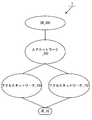
- FIG. 1 is a diagram for explaining the outline of the mobile communication system 1
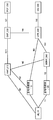
- FIG. 2 is a diagram for explaining the detailed configuration of the mobile communication system 1.
- FIG. 1 shows that the mobile communication system 1 is composed of UE (User Equipment) _10, access network _100, access network _102, core network _200, and DN (Data Network) _300.
- UE User Equipment
- DN Data Network
- these devices / networks may be described by omitting symbols such as UE, access network, core network, DN and the like.
- FIG. 2 shows UE_10, base station device_110, base station device_120, AMF (Access and Mobility Management Function) _210, SMF (Session Management Function) _220, UPF (User Plane Function) _230, N3IWF (Non). -3GPP InterWorking Function) _240, PCF (Policy Control Function) _250, DN_300 and other device / network functions, and interfaces for connecting these devices / network functions to each other are described. Note that these devices / network functions may be described by omitting symbols such as UE, base station device, AMF, SMF, UPF, N3IWF, PCF, DN, etc.
- 5GS which is a 5G system, is configured to include a UE, an access network, and a core network, but may further include a DN.
- the UE is a device that can connect to network services via 3GPP access (3GPP access network, also called 3GPP AN) and / or non-3GPP access (non-3GPP access network, also called non-3GPP AN). is there.
- the UE may be a terminal device capable of wireless communication such as a mobile phone or a smartphone, and may be a terminal device capable of connecting to EPS (Evolved Packet System), which is a 4G system, or 5GS.
- EPS Evolved Packet System
- the UE may be provided with UICC (Universal Integrated Circuit Card) or eUICC (Embedded UICC).
- the UE may be expressed as a user device or a terminal device.
- the UE is a device that can use the ATSSS (Access Traffic Steering, Switching and Splitting) function, that is, an ATSSS capable UE.
- ATSSS Access Traffic Steering, Switching and Splitting
- the access network may also be referred to as a 5G access network (5G AN).
- 5GAN is composed of NG-RAN (NG Radio Access Network) and / or non-3GPP access network (non-3GPPAN).
- NG-RAN NG Radio Access Network
- non-3GPPAN non-3GPP access network
- One or more base chrysanthemum devices are installed in NG-RAN.
- the base station device may be gNB.
- gNB is a node that provides the NR (New Radio) user plane and control plane to the UE, and is a node that connects to 5GC via an NG interface (including an N2 interface or an N3 interface). That is, gNB is a newly designed base station device for 5GS and has a different function from the base station device (eNB) used in EPS.
- eNB base station device
- each gNB is connected to each other by, for example, an Xn interface.
- the base station device_110 corresponds to gNB
- NG-RAN may be referred to as 3GPP access.
- wireless LAN access network and non-3GPP AN may be referred to as non-3GPP access.
- the nodes arranged in the access network may be collectively referred to as NG-RAN nodes.
- the device included in the access network and / or the device included in the access network may be referred to as an access network device.
- access network_100 supports 3GPP access
- access network_102 supports non-3GPP access.
- the base station device_110 is arranged in the access network_100, and the base station device_120 is arranged in the access network_102.
- the base station device_110 and the base station device_120 may be able to use the ATSSS function.
- access network_102 may be referred to as Untrusted Non-3GPP Access or Trusted Non-3GPP Access.
- the base station device 120 and N3IWF in FIG. 2 describe the case of Untrusted Non-3GPP Access. That is, when the access network_102 is Untrusted Non-3GPP Access, the base station device _120 and N3IWF are used.
- the access network_102 is Trusted Non-3GPP Access (also referred to as Trusted Non-3GPP Access Network, TNAN), instead of base station device _120 and N3IWF, it is also referred to as Trusted Non-3GPP Access Point (also referred to as TNAP). )
- Trusted Non-3GPP Gateway Function also called TNGF
- TNAP and TNGF are located on access network _102 or core network _200.
- the core network is compatible with 5GC (5G Core Network).
- 5GC 5G Core Network
- AMF, UPF, SMF, PCF and the like are arranged in 5GC.
- 5GC may be expressed as 5GCN (5G Core Network).
- the AMF, UPF, SMF, and PCF may be able to use the ATSSS function.
- N3IWF is located in access network_102 or core network_200.
- the core network and / or the device included in the core network may be referred to as a core network device.
- the core network may be an IP mobile communication network operated by a mobile network operator (MNO) that connects the access network and the DN, or a mobile network operator 1 that operates and manages the mobile communication system 1. It may be a core network for a mobile network operator, or a core network for a virtual mobile network operator such as MVNO (Mobile Virtual Network Operator) or MVNE (Mobile Virtual Network Enabler) or a virtual mobile communication service provider. ..
- MNO mobile network operator
- MVNE Mobile Virtual Network Enabler
- the DN may be a DN that provides a communication service to the UE.
- the DN may be configured as a packet data service network or may be configured for each service.
- the DN may include a connected communication terminal. Therefore, connecting to the DN may be connecting to a communication terminal or server device arranged in the DN. Further, sending and receiving user data to and from the DN may be sending and receiving user data to and from a communication terminal or server device arranged in the DN.
- At least a part of an access network, a core network, a DN, and / or one or more devices included in these may be referred to as a network or a network device. That is, a network and / or network device sending and receiving messages and / or performing a procedure means that an access network, a core network, at least a portion of a DN, and / or one or more devices contained therein. , Sending and receiving messages, and / or performing procedures.
- the UE can connect to the access network.
- the UE can also connect to the core network via the access network.
- the UE can connect to the DN via the access network and the core network. That is, the UE can send / receive (communicate) user data with the DN.
- IP Internet Protocol
- non-IP communication may be used.
- IP communication is data communication using IP, and data is transmitted and received by IP packets.
- An IP packet is composed of an IP header and a payload part.
- the payload section may include devices / functions included in EPS and data transmitted / received by devices / functions included in 5GS.
- non-IP communication is data communication that does not use IP, and data is transmitted and received in a format different from the structure of IP packets.
- non-IP communication may be data communication realized by sending and receiving application data to which an IP header is not added, or a UE can add another header such as a Mac header or an Ethernet (registered trademark) frame header.
- User data to be sent and received may be sent and received.
- each device may be configured as physical hardware, may be configured as logical (virtual) hardware configured on general-purpose hardware, or may be configured as software. May be done. Further, at least a part (including all) of the functions of each device may be configured as physical hardware, logical hardware, or software.
- each storage unit (storage unit_330, storage unit_440, storage unit_540) in each device / function appearing below is, for example, a semiconductor memory, SSD (Solid State Drive), HDD (Hard Disk Drive). ) Etc.
- each storage unit has not only the information originally set from the shipping stage, but also devices / functions other than its own device / function (for example, UE and / or access network device, and / or core network device, and /.
- various information transmitted / received to / from PDN and / or DN can be stored.
- each storage unit can store identification information, control information, flags, parameters, and the like included in control messages transmitted and received in various communication procedures described later. Further, each storage unit may store such information for each UE.
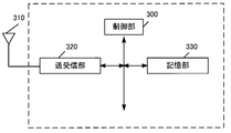
- the UE is composed of a control unit_300, an antenna_310, a transmission / reception unit_320, and a storage unit_330.
- the control unit_300, the transmission / reception unit_320, and the storage unit_330 are connected via a bus.
- the transmitter / receiver_320 is connected to the antenna_310.
- Control unit_300 is a functional unit that controls the operation and functions of the entire UE.
- the control unit_300 may process all the functions that the other functional units (transmission / reception unit_320, storage unit_330) in the UE do not have.
- the control unit _300 realizes various processes in the UE by reading and executing various programs stored in the storage unit _330 as needed.
- the transmission / reception unit_320 is a functional unit for wireless communication with a base station device or the like in the access network via the antenna_310. That is, the UE can send and receive user data and / or control information to and from the access network device and / or the core network device and / or the DN by using the transmission / reception unit_320.
- the UE can communicate with the base station device_110, the base station device_120, and TNAP by using the transmission / reception unit_320. That is, the UE communicates with the base station device_110 when communicating via 3GPP access. The UE also communicates with base station device_120 or TNAP when communicating via non-3GPP access. More specifically, the UE communicates with the base station device_120 when communicating via Untrusted non-3GPP Access, and the UE communicates with TNAP when communicating via Trusted non-3GPP Access. .. In this way, the UE can change the connection destination according to the access network to be used.
- the UE can communicate with the core network device (AMF, SMF, UPF, etc.) by using the transmitter / receiver _320.
- AMF core network device
- SMF SMF
- UPF User Plane Function
- the UE can send and receive AMF and NAS (Non-Access-Stratum) messages via the N1 interface (the interface between the UE and AMF).
- the N1 interface is a logical interface, communication between the UE and AMF is actually performed via base station device_110, base station device_120, and TNAP.
- the UE can communicate with AMF via base station device_110 when communicating via 3GPP access.
- the UE can communicate with AMF via base station device_120 and N3IWF.
- the UE can communicate with AMF via TNAP and TNGF.
- the information exchanged between the UE and AMF is mainly control information.
- the UE can communicate with the SMF using the N1 interface and the N11 interface (the interface between the AMF and the SMF). Specifically, the UE can communicate with the SMF via the AMF. As described above, the communication path between the UE and AMF may follow three types of routes depending on the access (3GPP access, Untrusted Non-3GPP Access, Trusted Non-3GPP Access).
- the information exchanged between the UE and SMF is mainly control information.
- the UE can communicate with the UPF using the N3 interface (the interface between the access network and the UPF). Specifically, the UE can communicate with the UPF via base station device_110 when communicating via 3GPP access. Further, when the UE communicates via non-3GPP access (Untrusted non-3GPP Access), the UE can communicate with the UPF via the base station device _120 and N3IWF. In addition, the UE can communicate with the UPF via TNAP and TNGF when communicating via non-3GPP access (Trusted non-3GPP Access).
- the communication path between the UE and UPF is mainly used to send and receive user data.
- the UE can communicate with the PCF using the N1 interface, the N11 interface, and the N7 interface (the interface between the SMF and the PCF). Specifically, the UE can communicate with the PCF via AMF and SMF. As described above, the communication path between the UE and AMF may follow three types of routes depending on the access (3GPP access, Untrusted Non-3GPP Access, Trusted Non-3GPP Access). The information exchanged between the UE and the PCF is mainly control information.
- UE can communicate with DN using N3 interface and N6 interface (interface between UPF and DN). Specifically, when communicating via 3GPP access, the UE can communicate with the DN via base station device_110 and UPF. In addition, when communicating via non-3GPP access (Untrusted non-3GPP Access), the UE can communicate with DN via base station device_120, N3IWF, and UPF. In addition, when communicating via non-3GPP access (Trusted non-3GPP Access), the UE can communicate with DN via TNAP, TNGF, and UPF.
- the communication path between the UE and DN that is, the PDU session or MAPDU session, is mainly used to send and receive user data.
- the above only describes the communication between the UE and a typical device / function in the present specification, and the UE can communicate with a device / function other than the above, that is, a core network device other than the above. Needless to say.
- the storage unit_330 is a functional unit for storing programs, user data, control information, etc. required for each operation of the UE.
- the UE is a UE that supports the ATSSS function, and it is desirable that the control information received from the core network side be stored in the storage unit_330. Then, the control unit _300 performs communication using the MA PDU session or communicates using the SA PDU session according to the control information received from the core network side or the control information stored in the storage unit _330. It may have a function of determining whether or not. Also, when communicating using a MAPDU session, determine whether to communicate via 3GPP access only, non-3GPP access only, or 3GPP access and non-3GPP access. can do. In addition, when communicating using the SA PDU session, it is possible to determine whether to communicate only via 3GPP access or only non-3GPP access. The control unit_300 controls the transmission / reception unit 320 so that it can communicate appropriately according to these decisions.
- the UE when communicating using a MAPDU session, the UE may have a function of deciding which access the uplink traffic should be routed to according to the ATSSS rules received from the SMF.
- the UE may have a function of requesting the establishment of a MA PDU session based on the URSP rules received from the PCF.
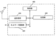
- Base station device_110 is a base station device located in 3GPP access.
- the base station device_110 is composed of a control unit_400, an antenna_410, a network connection unit_420, a transmission / reception unit_430, and a storage unit_440.
- the control unit_400, network connection unit_420, transmission / reception unit_430, and storage unit_440 are connected via a bus.
- the transmitter / receiver_430 is connected to the antenna_410.
- the base station device_110 may be a base station device that supports the ATSSS function.
- Control unit_400 is a functional unit that controls the operation and functions of the entire base station device_110. Note that the control unit_400 may process all the functions that the other functional units (network connection unit_420, transmission / reception unit_430, storage unit_440) in the base station device_110 do not have. The control unit _400 realizes various processes in the base station device _110 by reading and executing various programs stored in the storage unit _440 as needed.
- the network connection unit_420 is a functional unit for the base station device_110 to communicate with the AMF and / or the UPF. That is, the base station device_110 can send and receive control information and / or user data to and from the AMF and / or the UPF or the like by using the network connection unit_420.
- the base station device_110 can communicate with the AMF via the N2 interface (the interface between the access network and the AMF) by using the network connection unit_420. Further, the base station device_110 can communicate with the UPF via the N3 interface by using the network connection unit_420.
- the transmitter / receiver_430 is a functional unit for wireless communication with the UE via the antenna_410. That is, the base station device_110 can transmit / receive user data and / or control information between the UE and the UE by using the transmission / reception unit_430 and the antenna_410.
- the base station device_110 has a function of transmitting user data and / or control information to the core network device when the user data and / or control information addressed to the core network device is received from the UE. Further, the base station device_110 has a function of transmitting the user data and / or the control information to the UE when the user data and / or the control information addressed to the UE is received from the core network device.
- the above only describes the communication between the base station device_110 and a typical device / function, and the base station device_110 communicates with a device / function other than the above, that is, a core network device other than the above. It goes without saying that you can do it.
- the storage unit_440 is a functional unit for storing programs, user data, control information, etc. required for each operation of the base station device_110.
- the base station apparatus_120 is a base station apparatus arranged in non-3GPP access (Untrusted non-3GPP Access).
- the base station device_120 is composed of a control unit_400, an antenna_410, a network connection unit_420, a transmission / reception unit_430, and a storage unit_440.
- the control unit_400, network connection unit_420, transmission / reception unit_430, and storage unit_440 are connected via a bus.
- the transmitter / receiver_430 is connected to the antenna_410.
- the base station device_120 may be a base station device that supports the ATSSS function.
- Control unit_400 is a functional unit that controls the operation and functions of the entire base station device_120.
- the control unit _400 may process all the functions that the other functional units (network connection unit _420, transmission / reception unit _430, storage unit _440) in the base station device _120 do not have.
- the control unit _400 realizes various processes in the base station apparatus _120 by reading and executing various programs stored in the storage unit _440 as needed.
- the network connection unit_420 is a functional unit for the base station device_120 to communicate with the N3IWF, and is a functional unit for communicating with the AMF and / or UPF via the N3IWF. That is, the base station device_120 can send and receive control information and / or user data to and from the N3IWF by using the network connection unit_420. Further, the base station device_120 can transmit / receive control information and / or user data to / from the AMF and / or the UPF or the like by using the network connection unit_420.
- the base station device_120 can communicate with the N3IWF via the Y2 interface (the interface between the access network and the N3IWF) by using the network connection unit_420.
- the base station device_120 can communicate with the AMF via the N2 interface (the interface between the N3IWF and the AMF) via the N3IWF.
- the base station device_120 can communicate with the UPF via the N3 interface (the interface between the N3IWF and the UPF) via the N3IWF.
- the transmitter / receiver_430 is a functional unit for wireless communication with the UE via the antenna_410. That is, the base station apparatus_120 uses the transmitter / receiver _430 and the antenna_410 to transmit user data and / or control information to and from the UE via the Y1 interface (interface between the access network and the UE). You can send and receive.
- the base station device_120 has a function of transmitting the user data and / or the control information to the core network device when the user data and / or the control information addressed to the core network device is received from the UE. Further, the base station apparatus_120 has a function of transmitting the user data and / or the control information to the UE when the user data and / or the control information addressed to the UE is received from the core network apparatus.
- the base station device_120 only describes the communication between the base station device_120 and a typical device / function, and the base station device_120 communicates with a device / function other than the above, that is, a core network device other than the above. It goes without saying that you can do it.
- the storage unit_440 is a functional unit for storing programs, user data, control information, etc. required for each operation of the base station device_120.
- TNAP is a base station device (also referred to as an access point) located in non-3GPP access (Trusted non-3GPP Access).
- TNAP is composed of a control unit_400, an antenna_410, a network connection unit_420, a transmission / reception unit_430, and a storage unit_440.
- the control unit_400, network connection unit_420, transmission / reception unit_430, and storage unit_440 are connected via a bus.
- the transmitter / receiver_430 is connected to the antenna_410.
- the TNAP may be a TNAP that supports the ATSSS function.
- Control unit_400 is a functional unit that controls the operation and functions of the entire TNAP.
- the control unit_400 may process all the functions that the other functional units (network connection unit_420, transmission / reception unit_430, storage unit_440) in TNAP do not have.
- the control unit _400 realizes various processes in TNAP by reading and executing various programs stored in the storage unit _440 as needed.
- the network connection unit_420 is a functional unit for TNAP to communicate with TNGF, and is a functional unit for communicating with AMF and / or UPF via TNGF. That is, TNAP can send and receive control information and / or user data to and from TNGF using the network connection unit_420. In addition, TNAP can send and receive control information and / or user data to and from AMF and / or UPF, etc. using the network connection unit_420.
- TNAP can communicate with TNGF via the Ta interface (the interface between TNAP and TNGF) by using the network connection part_420.
- TNAP can communicate with AMF via N2 interface (interface between TNGF and AMF) via TNGF.
- TNAP can communicate with UPF via N3 interface (interface between TNGF and UPF) via TNGF.
- the transmitter / receiver_430 is a functional unit for wireless communication with the UE via the antenna_410. That is, TNAP can send and receive user data and / or control information to and from the UE via the Yt interface (interface between TNAP and UE) using the transmitter / receiver _430 and antenna_410. ..
- TNAP has a function of transmitting user data and / or control information to the core network device when it receives user data and / or control information addressed to the core network device from the UE. Further, TNAP has a function of transmitting user data and / or control information to the UE when the user data and / or control information addressed to the UE is received from the core network device.
- TNAP can communicate with a device / function other than the above, that is, a core network device other than the above. ..
- the storage unit_440 is a functional unit for storing programs, user data, control information, etc. required for each operation of TNAP.
- N3IWF is a device and / or function that is placed between non-3GPP access and 5GC when the UE connects to 5GS via non-3GPP access (Untrusted non-3GPP Access). It is located in non-3GPP access (Untrusted non-3GPP Access) or core network.
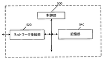
- N3IWF consists of a control unit_500, a network connection unit_520, and a storage unit_540. The control unit_500, network connection unit_520, and storage unit_540 are connected via a bus. Further, the N3IWF may be an N3IWF that supports the ATSSS function.
- Control unit_500 is a functional unit that controls the operation and functions of the entire N3IWF. Note that the control unit_500 may process all the functions that the other functional units (network connection unit_520, storage unit_540) in the N3IWF do not have. The control unit_500 realizes various processes in the N3 IWF by reading and executing various programs stored in the storage unit_540 as needed.
- the network connection unit_520 is a functional unit for N3IWF to communicate with the base station device_120 and / or AMF and / or UPF. That is, the N3IWF can send and receive control information and / or user data to and from the base station device_120 using the network connection unit_520. In addition, N3IWF can send and receive control information and / or user data to and from AMF and / or UPF, etc. using the network connection unit_520.
- N3IWF can communicate with the base station device_120 via the Y2 interface by using the network connection part_520.
- the N3IWF can also communicate with the AMF via the N2 interface.
- N3IWF can also communicate with UPF via the N3 interface.
- the above only describes the communication between the N3IWF and a typical device / function, and it goes without saying that the N3IWF can communicate with a device / function other than the above, that is, a core network device other than the above. ..
- the storage unit_540 is a functional unit for storing programs, user data, control information, etc. required for each operation of N3IWF.
- N3IWF has a function to establish an IPsec tunnel between the UE and an IPsec tunnel, a function to terminate the N2 interface for the control plane, a function to terminate the N3 interface for the user plane, a function to relay NAS signaling between the UE and AMF, and a PDU session.
- Ability to process N2 signaling from SMF with respect to and QoS a function to establish IPsec SA (Security Association) to support PDU session traffic, a function to relay userplane packets between UE and UPF (IPsec) Includes packet encapsulation / decapsulation for N3 tunnels), functions as a local mobility anchor within an untrusted non-3GPP access network, and the ability to select AMF. All of these functions are controlled by control unit_500.
- TNGF is a device and / or function that is placed between non-3GPP access and 5GC when the UE connects to 5GS via non-3GPP access (Trusted non-3GPP Access). It is located in non-3GPP Access (Trusted non-3GPP Access) or in the core network.
- the TNGF is composed of a control unit_500, a network connection unit_520, and a storage unit_540. The control unit_500, network connection unit_520, and storage unit_540 are connected via a bus. Also, the TNGF may be a TNGF that supports the ATSSS function.
- Control unit_500 is a functional unit that controls the operation and functions of the entire TNGF.
- the control unit_500 may process all the functions that the other functional units (network connection unit_520, storage unit_540) in the TNGF do not have.
- the control unit _500 realizes various processes in the TNGF by reading and executing various programs stored in the storage unit _540 as needed.
- Network connection _520 is a functional unit for TNGF to communicate with TNAP and / or AMF and / or UPF. That is, the TNGF can send and receive control information and / or user data to and from TNAP using the network connection unit_520. In addition, the TNGF can send and receive control information and / or user data to and from the AMF and / or the UPF, etc. using the network connection unit_520.
- TNGF can communicate with TNAP via the Y2 interface by using the network connection part_520.
- the TNGF can also communicate with the AMF via the N2 interface.
- TNGF can also communicate with UPF via the N3 interface.
- the above only describes the communication between the TNGF and a typical device / function, and it goes without saying that the TNGF can communicate with a device / function other than the above, that is, a core network device other than the above. ..
- the storage unit_540 is a functional unit for storing programs, user data, control information, etc. required for each operation of TNGF.
- TNGF has a function to terminate N2 interface and N3 interface, a function to act as an approver when UE registers with 5GC via TNAN, a function to select AMF, and a NAS message between UE and AMF.
- the AMF consists of a control unit_500, a network connection unit_520, and a storage unit_540.
- the control unit_500, network connection unit_520, and storage unit_540 are connected via a bus.
- the AMF may be a node that handles the control plane. Further, the AMF may be an AMF that supports the ATSSS function.
- Control unit_500 is a functional unit that controls the operation and functions of the entire AMF.
- the control unit_500 may process all the functions that the other functional units (network connection unit_520, storage unit_540) in the AMF do not have.
- the control unit_500 realizes various processes in AMF by reading and executing various programs stored in the storage unit_540 as needed.
- the network connection part_520 is a functional part for AMF to connect to the base station equipment in 5GAN and / or SMF and / or PCF, and / or UDM, and / or SCEF. That is, the AMF uses the network connection _520 to communicate with the base station equipment in 5GAN and / or SMF and / or PCF, and / or UDM, and / or SCEF. Alternatively, control information can be transmitted and received.
- the AMF in the 5GC can communicate with the base station device via the N2 interface by using the network connection _520, and the N8 interface (AMF and UDM). Can communicate with UDM via interface between), can communicate with SMF via N11 interface, and can communicate with PCF via N15 interface (interface between AMF and PCF) it can.
- AMF can send and receive NAS messages to and from the UE via the N1 interface by using the network connection unit_520.
- the N1 interface is logical, communication between the UE and AMF is actually done via 5GAN.
- the storage unit_540 is a functional unit for storing programs, user data, control information, etc. required for each operation of AMF.
- AMF has a function to exchange control messages with RAN using the N2 interface, a function to exchange NAS messages with UE using the N1 interface, a function to encrypt and protect the integrity of NAS messages, and registration management.
- the RM status for each UE is managed.
- the RM state may be synchronized between the UE and AMF.
- the RM state includes a non-registered state (RM-DEREGISTERED state) and a registered state (RM-REGISTERED state).
- RM-DEREGISTERED state the UE is not registered in the network, so the UE context in the AMF does not have valid location information or routing information for the UE, so the AMF cannot reach the UE.
- the RM-REGISTERED state the UE is registered in the network, so the UE can receive services that require registration with the network.
- the RM state may be expressed as a 5GMM state (5GMM state).
- the RM-DEREGISTERED state may be expressed as 5GMM-DEREGISTERED state
- the RM-REGISTERED state may be expressed as 5GMM-REGISTERED state.
- the 5GMM-REGISTERED state may be a state in which each device has established a 5GMM context or a PDU session context.
- UE_10 may start sending and receiving user data and control messages, or may respond to paging. Further, when each device is in the 5GMM-REGISTERED state, UE_10 may execute a registration procedure other than the registration procedure for initial registration and / or a service request procedure.
- each device may be in a state where the 5GMM context has not been established, the location information of UE_10 may not be known to the network, or the network may be in the state of UE_10. It may be in an unreachable state.
- UE_10 may start the registration procedure or establish the 5GMM context by executing the registration procedure.
- the CM state may be synchronized between the UE and AMF.
- the CM state includes a non-connected state (CM-IDLE state) and a connected state (CM-CONNECTED state).
- CM-IDLE state the UE is in the RM-REGISTERED state, but does not have a NAS signaling connection established with the AMF via the N1 interface.
- N2 connection N2 connection
- N3 connection N3 interface connection
- the CM-CONNECTED state has a NAS signaling connection established with the AMF via the N1 interface.
- the CM-CONNECTED state the UE may have an N2 interface connection (N2 connection) and / or an N3 interface connection (N3 connection).
- the CM state in 3GPP access and the CM state in non-3GPP access may be managed separately.
- the CM state in 3GPP access may be a non-connected state in 3GPP access (CM-IDLE state over 3GPP access) and a connected state in 3GPP access (CM-CONNECTED state over 3GPP access).
- the CM state in non-3GPP access includes the non-connection state (CM-IDLE state over non-3GPP access) in non-3GPP access and the connection state (CM-CONNECTED state over non-3GPP access) in non-3GPP access. ) May be there.
- the disconnected state may be expressed as an idle mode
- the connected state mode may be expressed as a connected mode.
- the CM state may be expressed as 5GMM mode (5GMM mode).
- the non-connected state may be expressed as 5GMM non-connected mode (5GMM-IDLE mode)
- the connected state may be expressed as 5GMM connected mode (5GMM-CONNECTED mode).
- the disconnected state in 3GPP access may be expressed as 5GMM non-connection mode (5GMM-IDLE mode over 3GPP access) in 3GPP access
- the connection state in 3GPP access is 5GMM connection mode (5GMM-) in 3GPP access. It may be expressed as CONNECTED mode over 3GPP access).
- non-connection state in non-3GPP access may be expressed as 5GMM non-connection mode (5GMM-IDLE mode over non-3GPP access) in non-3GPP access, and the connection state in non-3GPP access is non. It may be expressed as 5GMM connection mode (5GMM-CONNECTED mode over non-3GPP access) in -3GPP access.
- the 5GMM non-connection mode may be expressed as an idle mode, and the 5GMM connection mode may be expressed as a connected mode.
- AMF may be placed in the core network.
- AMF may be an NF that manages one or more NSIs (Network Slice Instances).
- the AMF may be a shared CP function (CCNF; Common CPNF (Control Plane Network Function)) shared among a plurality of NSIs.
- CCNF Common CPNF (Control Plane Network Function)
- the SMF consists of a control unit_500, a network connection unit_520, and a storage unit_540.
- the control unit_500, network connection unit_520, and storage unit_540 are connected via a bus.
- the SMF may be a node that handles the control plane. Further, the SMF may be an SMF that supports the ATSSS function.
- Control unit_500 is a functional unit that controls the operation and functions of the entire SMF. Note that the control unit_500 may process all the functions that the other functional units (network connection unit_520, storage unit_540) in the SMF do not have. The control unit _500 realizes various processes in the SMF by reading and executing various programs stored in the storage unit _540 as needed.
- the network connection part_520 is a functional part for SMF to connect with AMF and / or UPF and / or PCF and / or UDM. That is, the SMF can send and receive user data and / or control information between the AMF and / or the UPF and / or the PCF and / or the UDM by using the network connection part_520.
- the SMF in the 5GC can communicate with the AMF via the N11 interface by using the network connection _520, and the N4 interface (between the SMF and UPF). It can communicate with the UPF via the interface), with the PCF via the N7 interface, and with the UDM via the N10 interface (the interface between the SMF and UDM).
- the storage unit_540 is a functional unit for storing programs, user data, control information, etc. required for each operation of the SMF.
- SMF has session management functions such as establishment, modification, and release of PDU sessions, IP address allocation and management functions for UEs, UPF selection and control functions, and appropriate destinations (appropriate destinations).
- SMF has a function to create ATSSS rules and N4 rules from PCC rules received from PCF.
- ATSSS rules are information for controlling MAPDU sessions sent from SMF to UE.
- N4 rules are information for controlling the MA PDU session sent from SMF to UPF.
- SMF has a function of associating and managing PCC rules, ATSSS rules, and N4 rules (also referred to as mapping). All of these functions are controlled by control unit_500.
- the UPF consists of a control unit_500, a network connection unit_520, and a storage unit_540.
- the control unit_500, network connection unit_520, and storage unit_540 are connected via a bus.
- the UPF may be a node that handles the user plane.
- the UPF may be a UPF that supports the ATSSS function.
- Control unit_500 is a functional unit that controls the operation and functions of the entire UPF. Note that the control unit_500 may process all the functions that the other functional units (network connection unit_520, storage unit_540) in the UPF do not have. The control unit _500 realizes various processes in the UPF by reading and executing various programs stored in the storage unit _540 as needed.
- the network connection unit_520 is a functional unit for the UPF to connect to the base station equipment in 5GAN and / or the SMF and / or the DN. That is, the UPF can send and receive user data and / or control information between the base station device in 5GAN and / or the SMF and / or the DN by using the network connection part_520.
- the UPF in the 5GC can communicate with the base station equipment via the N3 interface by using the network connection _520, via the N4 interface. It can communicate with SMF, can communicate with DN via N6 interface, and can communicate with other UPFs via N9 interface (interface between UPFs).
- the storage unit_540 is a functional unit for storing programs, user data, control information, etc. required for each operation of UPF.
- the UPF functions as an anchor point for intra-RAT mobility or inter-RAT mobility, and as an external PDU session point for interconnecting to the DN (that is, as a gateway between the DN and the core network, as a user.
- Data transfer function includes packet routing and transfer function, UL CL (Uplink Classifier) function that supports routing of multiple traffic flows to one DN, and multi-homed PDU session support.
- It has a branching point function, a QoS (Quality of Service) processing function for the user plane, a function for verifying uplink traffic, a function for buffering downlink packets, and a function for triggering downlink data notification (Downlink Data Notification).
- the UPF also has the function of deciding which access the downlink traffic should be routed to when the MAPDU session is established, based on the N4 rules received from the SMF. All of these functions are controlled by control unit_500.
- the UPF may also be a gateway for IP communication and / or non-IP communication.
- the UPF may have a function of transferring IP communication, or may have a function of converting non-IP communication and IP communication.
- the plurality of gateways arranged may be gateways connecting the core network and a single DN.
- the UPF may have connectivity with other NFs, or may be connected to each device via the other NFs.
- the user plane is user data sent and received between the UE and the network.
- the user plane may be sent and received using a PDU session. Further, in the case of 5GS, the user plane may be transmitted and received via the interface between the UE and NG RAN and / or the N3 interface and / or the N9 interface and / or the N6 interface.
- the user plane may be expressed as a U-Plane.
- control plane is a control message sent and received to control the communication of the UE.
- the control plane may be transmitted and received using a NAS (Non-Access-Stratum) signaling connection between the UE and AMF.
- NAS Non-Access-Stratum
- control plane may be transmitted and received using the interface between the UE and NG RAN and the N2 interface.
- the control plane may be expressed as a control plane or a C-Plane.
- the U-Plane (User Plane; UP) may be a communication path for transmitting and receiving user data, and may be composed of a plurality of bearers.
- the C-Plane (Control Plane; CP) may be a communication path for transmitting and receiving control messages, and may be composed of a plurality of bearers.
- the PCF is composed of a control unit_500, a network connection unit_520, and a storage unit_540.
- the control unit_500, network connection unit_520, and storage unit_540 are connected via a bus.
- the PCF may be a PCF that supports the ATSSS function.
- Control unit_500 is a functional unit that controls the operation and functions of the entire PCF. Note that the control unit_500 may process all functions that the other functional units (network connection unit_520, storage unit_540) in the PCF do not have. The control unit _500 realizes various processes in the PCF by reading and executing various programs stored in the storage unit _540 as needed.
- the network connection part_520 is a functional part for the PCF to connect with the SMF and / or AF (Application Function). That is, the PCF can send and receive control information to and from the SMF and / or AF by using the network connection unit_520.
- the PCF can communicate with the SMF via the N7 interface by using the network connection part_520.
- the PCF can communicate with the AF (Application Function) via the N5 interface (the interface between the PCF and the AF) by using the network connection unit_520.
- the storage unit_540 is a functional unit for storing programs, user data, control information, etc. required for each operation of UPF.
- PCF has a function to support a unified policy framework, a function to provide policy rules to a control function (control plane function) to enforce them, a function to access registration information, etc. have.
- the PCF also has the ability to generate policies for MA PDU sessions (also called PCC rules), policies for SA PDU sessions, and URSP rules. These are sent to the SMF, at least some of which may be sent to the UE or to the UPF. All of these functions are controlled by control unit_500.
- the network refers to at least a part of the access network, core network, and DN. Further, one or more devices included in at least a part of the access network, the core network, and the DN may be referred to as a network or a network device. That is, the fact that the network executes the transmission / reception and / or processing of messages may mean that the devices (network devices and / or control devices) in the network execute the transmission / reception and / or processing of messages. .. Conversely, the fact that a device in the network executes message transmission / reception and / or processing may mean that the network executes message transmission / reception and / or processing.
- SM session management
- NAS Non-Access-Stratum
- SM messages may be NAS messages used in procedures for SM, and are sent and received between UE and SMF via AMF. It may be a control message to be executed.
- SM messages include PDU session establishment request messages, PDU session establishment acceptance messages, PDU session completion messages, PDU session rejection messages, PDU session change request messages, PDU session change acceptance messages, PDU session change response messages, and the like. You may.
- the procedure for SM may include a PDU session establishment procedure.
- the 5GS (5G System) service may be a connection service provided using the core network. Further, the 5GS service may be a service different from the EPS service or a service similar to the EPS service.
- non 5GS service may be a service other than the 5GS service, and may include an EPS service and / or a non EPS service.
- DNN Data Network Name
- DN DN
- DNN can also be used as information for selecting a gateway such as UPF that connects the core network.
- the DNN may correspond to the APN (Access Point Name) in EPS.
- a PDU session can be defined as a relationship between a DN that provides a PDU connectivity service and a UE.
- a PDU session is between a UE and an external gateway or DN. It may be the connectivity established in.
- the UE can send and receive user data to and from the DN using the PDU session.
- the external gateway may be UPF, SCEF, or the like.
- the UE can use the PDU session to send and receive user data to and from devices such as application servers located in the DN.
- the PDU connectivity service is a service that provides PDU exchange between the UE and DN.
- this PDU session is composed of only userplane resources in one access network (3GPP access network or non-3GPP access network), and may be referred to as an SA PDU session. That is, the SA PDU session may be a PDU session that, unlike the MA PDU session, is not simultaneously composed of user plane resources in the 3GPP access network and user plane resources in the non-3GPP access network.
- each device may manage one or more identification information in association with each other for the PDU session.
- these identification information may include one or more of DNN, TFT, PDU session type, application identification information, NSI identification information, access network identification information, and SSC mode, and other information may be further included. May be included. Further, when a plurality of PDU sessions are established, the identification information associated with the PDU session may have the same content or different contents.
- the MA PDU session may be a PDU session that provides a PDU connectivity service capable of using one 3GPP access network and one non-3GPP access network at the same time.
- the MA PDU session may also be a PDU session that provides a PDU connectivity service that can use one 3GPP access network or one non-3GPP access network at any given time.
- the MAPDU session may consist only of userplane resources in the 3GPP access network, may consist only of userplaneresources in the non-3GPP access network, userplaneresources in the 3GPP access network and It may be configured at the same time by userplane resources in the non-3GPP access network.
- the fact that the UE communicates with the DN using the MAPDU session may mean that the UE communicates with the DN using only userplane resources in the 3GPP access network, or the UE communicates with the DN using the non-3GPP access network. It may be possible to communicate with the DN using only the userplane resources in the 3GPP access network, or it may be possible to communicate with the DN using the userplane resources in the 3GPP access network and the userplane resources in the non-3GPP access network. ..
- the UE can send and receive user data to and from a device such as an application server located in the DN by using the MAPDU session.
- each device may manage one or more identification information in association with each MA PDU session.
- these identification information may include one or more of DNN, TFT, PDU session type, application identification information, NSI identification information, access network identification information, and SSC mode, and other information may be further included. May be included. Further, when a plurality of MA PDU sessions are established, the identification information associated with the MA PDU session may have the same content or different contents.
- the PDU (Protocol Data Unit or Packet Data Unit) session type indicates the type of PDU session, and includes IPv4, IPv6, Ethernet (registered trademark), and Unstructured.
- IPv4 indicates that data is sent and received using IPv4.
- IPv6 indicates that data is sent and received using IPv6.
- Ethernet registered trademark
- Ethernet registered trademark
- Ethernet may indicate that communication using IP is not performed.
- Unstructured it indicates that data is sent and received to the application server etc. in the DN by using the point-to-point (P2P) tunneling technology.
- the PDU session type may include an IP in addition to the above.
- IP can be specified if the UE can use both IPv4 and IPv6.
- IP may also be expressed as IPv4 v6.
- a network slice is a logical network that provides specific network capabilities and network characteristics.
- UEs and / or networks can support network slices (NW slices; NS) in 5GS.
- a network slice instance is composed of an instance (entity) of a network function (NF) and a set of necessary resources, and forms a network slice to be arranged.
- NF is a processing function in a network and is adopted or defined in 3GPP.
- NSI is an entity of NS that consists of one or more in the core network.
- NSI may be configured by a virtual NF (Network Function) generated by using NST (Network Slice Template).
- NST Network Slice Template
- NST Network Slice Template
- NSI may be a logical network configured to separate user data delivered by services and the like.
- One or more NFs may be configured in NS.
- the NF configured in NS may or may not be a device shared with other NS.
- UE and / or devices in the network are 1 or more based on NSSAI and / or S-NSSAI and / or UE usage type and / or registration information such as 1 or more NSI IDs and / or APN. Can be assigned to NS.
- the UE usage type is a parameter value included in the UE registration information used to identify the NSI.
- the UE usage type may be stored in the HSS.
- AMF may select SMF and UPF based on UE usage type.
- S-NSSAI Single Network Slice Selection Assistance Information
- S-NSSAI may be composed of only SST (Slice / Service type), or may be composed of both SST and SD (Slice Differentiator).
- SST is information indicating the operation of NS expected in terms of functions and services.
- SD may be information for interpolating SST when selecting one NSI from a plurality of NSIs represented by SST.
- the S-NSSAI may be information peculiar to each PLMN, or may be standard information shared among PLMNs.
- the network may store one or more S-NSSAI in the UE registration information as the default S-NSSAI. If the S-NSSAI is the default S-NSSAI and the UE does not send a valid S-NSSAI to the network in the registration request message, the network may provide the NS related to the UE.
- NSSAI Network Slice Selection Assistance Information
- S-NSSAI Network Slice Selection Assistance Information
- Each S-NSSAI included in NSSAI is information that assists the access network or core network in selecting NSI.
- the UE may memorize the NSSAI permitted from the network for each PLMN.
- NSSAI may also be the information used to select AMF.
- SSC Session and Service Continuity
- SSC mode indicates the mode of session service continuity (Session and Service Continuity) supported by the system and / or each device in the 5G system (5GS). More specifically, it may be a mode indicating the types of session service continuation supported by the PDU session established between the UE and UPF.
- SSC mode may be a mode indicating the type of session service continuation set for each PDU session.
- the SSC mode may be composed of three modes, SSC mode 1, SSC mode 2, and SSC mode 3. Note that the SSC mode associated with the PDU session does not have to be changed for the life of the PDU session.
- SSC mode1 is a mode in which the network maintains the connectivity service provided to the UE.
- the PDU session type associated with the PDU session is IPv4 or IPv6, the IP address may be maintained when the session service is continued.
- SSC mode1 may be a session service continuation mode in which the same UPF is maintained regardless of the access technology used when the UE connects to the network. More specifically, SSC mode1 is a mode that realizes session service continuation even when UE mobility occurs, without changing the UPF used as the PDU session anchor of the established PDU session. Good.
- SSC mode2 is a mode in which the network releases the connectivity service provided to the UE and the corresponding PDU session.
- the PDU session type associated with the PDU session is IPv4, IPv6 or IPv4v6, even if the IP address assigned to the UE is released when changing the anchor of the PDU session. Good.
- SSC mode 2 may be a mode of session service continuation in which the same UPF is maintained only within the serving area of the UPF. More specifically, SSC mode 2 may be a mode that realizes session service continuation without changing the UPF used by the established PDU session as long as the UE is within the serving area of the UPF. Furthermore, SSC mode2 is a mode that realizes session service continuation by changing the UPF used by the established PDU session when UE mobility occurs, such as leaving the serving area of the UPF. Good.
- the serving area of the UPF may be an area where one UPF can provide the session service continuation function, or a subset of the access network such as RAT and cells used when the UE connects to the network. It may be. Further, the subset of access networks may be a network composed of one or more RATs and / or cells.
- the change of the anchor point of the PDU session of SSC mode 2 may be realized by each device executing the anchor point change procedure of the PDU session of SSC mode 2.
- the anchor or the anchor point may be expressed as an end point.
- SSC mode 3 is a mode in which changes in the user plane are revealed to the UE while the network guarantees that connectivity will not be lost.
- SSC mode3 in order to realize better connectivity service, a PDU session passing through a new PDU session anchor point may be established before the established PDU session is disconnected.
- the PDU session type associated with the PDU session is IPv4, IPv6 or IPv4v6, the IP address assigned to the UE is not maintained when changing the anchor of the PDU session. May be good.
- SSC mode 3 has a PDU session established between the UE and the UPF, and / or a new PDU session via the new UPF for the same DN before disconnecting the communication path, and / Alternatively, the mode may be a session service continuation mode that allows the establishment of a communication path. Further, SSC mode 3 may be a session service continuation mode that allows the UE to become multihoming. Furthermore, SSC mode 3 may be a mode in which session service continuation using a plurality of PDU sessions and / or UPFs associated with PDU sessions is permitted. In other words, in the case of SSC mode3, each device may realize the session service continuation by using a plurality of PDU sessions, or may realize the session service continuation by using a plurality of UPFs.
- the selection of the new UPF may be carried out by the network, and the new UPF is where the UE connects to the network. It may be the most suitable UPF.
- the UE immediately implements the mapping of the application and / or flow communication to the newly established PDU session. It may be carried out based on the completion of communication.
- the change of the anchor point of the SSC mode 3 PDU session may be realized by each device executing the anchor point change procedure of the SSC mode 3 PDU session.
- the default SSC mode is the SSC mode used by the UE and / or the network when a specific SSC mode is not determined.
- the default SSC mode is the SSC mode used by the UE when there is no SSC mode request from the application and / or when there is no UE policy to determine the SSC mode for the application. May be good.
- the default SSC mode may be the SSC mode used by the network when there is no request for the SSC mode from the UE.
- the default SSC mode may be set for each DN, may be set for each PDN, or may be set for each PDN, based on the subscriber information and / or the operator policy and / or the UE policy. , And / or may be set for each subscriber. Further, the default SSC mode may be information indicating SSC mode 1, SSC mode 2, or SSC mode 3.
- IP address preservation is a technology that allows you to continue to use the same IP address. If IP address maintenance is supported, the UE can continue to use the same IP address for user data communication even when moving out of the TA. In other words, if IP address maintenance is supported, each device may be able to continue to use the same IP address for user data communication even when the anchor point of the PDU session changes. ..
- the steering feature also allows ATSSS-enabled UEs to steer, switch, and split traffic in MAPDU sessions via 3GPP and non-3GPP access. It may be a function.
- the steering function may include an MPTCP (Multi-Path Transmission Control Protocol) function and an ATSSS (Access Traffic Steering, Switching, Splitting) -LL (Low-Layer) function.
- MPTCP Multi-Path Transmission Control Protocol
- ATSSS Access Traffic Steering, Switching, Splitting
- -LL Low-Layer
- the MPTCP function is a steering function for layers above the IP layer and is applied to TCP traffic. Traffic to which the MPTCP function is applied may be referred to as an MPTCP flow.
- the MPTCP function of the UE can communicate with the MPTCP proxy function of the UPF using the user plane of 3GPP access and / or non-3GPP access. Also, if the UE requests a MAPDU session and provides MPTCP capability, the MPTCP function may be enabled, and if the UPF agrees to enable the MPTCP function, the UPF will enable the MPTCP Proxy function. You can be.
- the network also assigns one IP address / prefix and two IP addresses / prefixes (also called link-specific multipath addresses) for MAPDU sessions.
- One of the link-specific multipath addresses is used to establish a subflow via 3GPP access and the other is used to establish a subflow via non-3GPP access.
- the link-specific multicast address is used only for the MPTCP function of the UE. Cannot route via N6.
- the network can send MPTCP proxy information (which may include the IP address, port number, and type of MPTCP proxy) to the UE.
- the type may be Type 1 (transport converter).
- the network may also provide the UE with a list of apps to which the MPTCP feature should be applied.
- the ATSSS-LL function is a steering function in the layer below the IP layer, and is applied to all types of traffic (TCP traffic, UDP (User Data Protocol) traffic, ethernet traffic, etc.). Traffic to which the ATSSS-LL function is applied may be referred to as Non-MPTCP flow.
- the UPF may also support steering functions that are the same as or similar to the ATSSS-LL function.
- the ATSSS-LL function of the UE determines the steering, switch, and split of upstream traffic based on the ATSSS rules and local conditions.
- the ATSSS-LL function may be enabled, and if the UE provides ATSSS-LL capability, the ATSSS-LL function in UPF is enabled. May become.
- ATSSS rules is a list of one or more ATSSS rules.
- the ATSSS rule may be composed of a rule priority (Rule Precedence) and / or a traffic descriptor (Traffic Descriptor) and / or an access selection descriptor (Access Selection Descriptor).
- Rule Precedence in ATSSS rule defines the order of ATSSS rules evaluated in UE.
- the UE may refer to the Rule Precedence in each ATSSS rule and evaluate in order from the highest priority ATSSS rule.
- the Traffic Descriptor in the ATSSS rule indicates when to apply the ATSSS rule.
- the Traffic Descriptor in the ATSSS rule may be composed of an application descriptor and / or an IP descriptor and / or a non-IP descriptor.
- the Application descriptors may also indicate information that identifies the application that generates the traffic.
- IP descriptors may indicate information that identifies the destination of IP traffic.
- non-IP descriptors may indicate information that identifies the destination of non-IP traffic (for example, ethernet traffic or unstructured traffic).
- the Access Selection Descriptor in the ATSSS rule may be composed of a steering mode and / or a steering function.
- the steering mode may be information indicating whether the traffic of the service data flow (also referred to as SDF) should be distributed to 3GPP access or non-3GPP access. Further, the steering mode may include four modes of Active-Standby, Smallest Delay, Load-Balancing, and Priority-based.
- Active-Standby sets active access and standby access, and when active access is available, steers the service data flow (SDF) for that access, and that active access is used. When it becomes impossible, it may be a mode to switch SDF to standby access.
- Active-Standby sets only active access, and if standby access is not set, it steers the service data flow (SDF) for that access when active access is available. The mode may be such that the SDF cannot be switched to standby access even if active access becomes unavailable.
- Smallest Delay may be a mode in which the service data flow (SDF) is steered for an access having the minimum RTT (Round-Trip Time). Also, when this mode is set, the UE and UPF may make measurements to determine the RTT when communicating via 3GPP access and the RTT when communicating via non-3GPP access.
- SDF service data flow
- RTT Red-Trip Time
- Load-Balancing may be a mode that separates the service data flow (SDF) for both accesses. If Load-Balancing is specified, it may also include information indicating the percentage of service data flow (SDF) that should be sent via 3GPP access and non-3GPP access.
- SDF service data flow
- Priority-based is also used to steer all traffic in the service data flow (SDF) for high priority access until it is determined to be congested. Mode may be used. If it is determined that the access is congested, the SDF traffic will be sent not only to the high-priority access but also to the low-priority access. Mode may be. Further, when high priority access becomes unavailable, all the traffic of SDF may be sent to low priority access.
- SDF service data flow
- the steering function may also indicate whether the MPTCP function or the ATSSS-LL function should be used to steer the traffic of the service data flow (also referred to as SDF). It may also be the information used if the UE supports both the MPTCP and ATSSS-LL features.
- the URSP (UE Route Selection Policy) rules may be composed of one or more URSP (UE Route Selection Policy Rule) rules paste.
- each URSP rule may be composed of a rule priority (Rule Precedence) and / or a traffic descriptor (Traffic descriptor) and / or a route selection descriptor list (List of Route Selection Descriptors).
- Rule Precedence in URSP rule indicates the order of URSP rules enforced in UE.
- the UE may refer to the Rule Precedence in each URSP rule and apply the URSP rules in order from the highest priority.
- Traffic descriptor in the URSP rule indicates when to apply the URSP rule.
- Traffic descriptors in the URSP rule are Application descriptors and / or IP descriptors, and / or Domain descriptors, and / or Non-IP descriptors. ), And / or DNN (Data Network Name), and / or Connection Capabilities.
- Application descriptors may include an OS ID and an OS application ID.
- IP descriptors indicate information that identifies a destination of IP traffic, and may include, for example, an IP address, an IPv6 network prefix, a port number, a protocol number, and the like.
- domain descriptors may indicate the FQDN (Fully Qualified Domain Name) of the destination.
- non-IP descriptors may indicate information that identifies the destination of non-IP traffic (for example, ethernet traffic or unstructured traffic).
- the DNN may also be information about the DNN provided by the application. Connection Capabilities may also indicate the information provided by the UE's application when the UE requests a connection to the network using its capabilities.
- the List of Route Selection Descriptors in the URSP rule may be composed of one or more route selection descriptors (Route Selection Descriptors).
- Each Route Selection Descriptor may be composed of the priority of the rule selection descriptor (Route Selection Descriptor Precedence) and / or the components of the route selection (Route selection components).
- RouteSelectionDescriptorPrecedence indicates the order in which RouteSelectionDescriptors are applied.
- the UE may refer to the Rule Precedence in each Route Selection Descriptor and apply the Route Selection Descriptors in order from the highest priority.
- RouteSelectionDescriptor is SSC mode selection (SSC Mode Selection) and / or network slice selection (Network Slice Selection) and / or DNN selection (DNN Selection) and / or PDU session type selection (PDU Session Type Selection). ), And / or a non-seamless offload indication, and / or an access type preference.
- SSCModeSelection may indicate that application traffic is routed through a specified SSC mode PDU session.
- Network Slice Selection may also indicate that it routes application traffic using the indicated PDU sessions that support one or more S-NSSAI.
- DNN Selection may also indicate that it routes application traffic using a PDU session that supports one or more of the indicated DNNs.
- this RouteSelectionDescriptor does not have to include DNNSelection.
- PDU session type selection may indicate that application traffic is routed using PDU sessions that support the indicated PDU session types.
- Non-Seamless Offload indication may indicate offloading application traffic for non-3GPP access.
- the AccessType preference may indicate the access type for establishing the PDU session when the UE needs to establish the PDU session.
- the access type may be 3GPP, non-3GPP, or multi-access. Multi-access may also indicate that the PDU session should be established as a MA PDU session with both 3GPP access and non-3GPP access.
- the first identification information is DNN. Further, the first identification information may be information indicating the DNN required by the UE. The first identification information may or may not be included in the PDU session establishment request message and / or the NAS message when the UE requests the establishment of the MA PDU session.
- the second identification information is information indicating whether or not the UE supports the ATSSS function.
- information indicating whether or not the UE supports the ATSSS function may be expressed as ATSSS capability.
- the second identification information also supports information indicating whether the UE supports the MPTCP function, which is one of the ATSSS functions, and / or the ATSSS-LL function, which is another function of the ATSSS function. It may be information indicating whether or not.
- the information indicating whether or not the MPTCP function is supported may be expressed as MPTCP capability
- the information indicating whether or not the ATSSS-LL function is supported may be expressed as ATSSS-LL capability.
- the UE can include MPTCP capability in the second identification information.
- the UE can include the ATSSS-LL capability in the second identification information.
- the second identification information can include the MPTCP capability and the ATSSS-LL capability.
- the third identification information is the PDU session ID. Further, the third identification information may be information indicating the PDU session ID requested by the UE (information for identifying the PDU session). Specifically, when the UE requests the establishment of a MA PDU session, the third identification information may be a PDU session ID for identifying the MA PDU session. When the UE requests the establishment of the MA PDU session, the third identification information is preferably included in the PDU session establishment request message and / or the NAS message.
- the fourth identification information is the PDU session type. Further, the fourth identification information may be information indicating the PDU session type requested by the UE. Further, the fourth identification information may be any one of IPv4, IPv6, IPv4v6, Unstructured, and Ethernet (registered trademark). Also, when the UE requests the establishment of a MA PDU session, the fourth identification information may be the PDU session type for the MA PDU session. The fourth identification information may or may not be included in the PDU session establishment request message and / or the NAS message when the UE requests the establishment of the MA PDU session.
- the fifth identification information is SSC mode. Further, the fifth identification information may be information indicating the SSC mode requested by the UE. Further, the fifth identification information may be any one of SSC mode 1, SSC mode 2, and SSC mode 3. Further, when the UE requests the establishment of the MA PDU session, the fifth identification information may be the SSC mode for the MA PDU session. The fifth identification information may or may not be included in the PDU session establishment request message and / or the NAS message when the UE requests the establishment of the MA PDU session.
- the sixth identification information is S-NSSAI. Further, the sixth identification information may be information indicating S-NSSAI requested by the UE. Also, when the UE requests the establishment of a MAPDU session, the sixth identity may be S-NSSAI, which is allowed for both accesses (3GPP access and non-3GPP access). Specifically, the sixth identification information is Allowed NSSAI (Network) included in the Registration Accept message received from the AMF in the Registration procedure performed by the UE to register with the 5GS. It may be one or more S-NSSAI included in NSSAI) permitted by. The sixth identification information may or may not be included in the PDU session establishment request message and / or the NAS message when the UE requests the establishment of the MA PDU session.
- NSSAI Network
- the seventh identification information is Request type.
- the seventh identification information is either an initial request, an existing PDU session (Existing PDU Session), an emergency request (Emergency Request), or an existing emergency PDU session (Existing Emergency PDU Session). May be shown.
- Initial request may be specified when requesting the establishment of a new PDU session.
- the Existing PDU Session may also be specified when switching an existing PDU session between 3GPP access and non-3GPP access, or when handing over from an existing PDN connection in an EPC to a 5G PDU session.
- EmergencyRequest may be specified when requesting the establishment of a PDU session for an emergency service.
- An existing Emergency PDU Session is a 5G PDU session when switching an existing PDU session for emergency service between 3GPP access and non-3GPP access, or from an existing PDN connection for emergency service in EPC. It may be specified when handing over to.
- the seventh identification information may or may not be included in the PDU session establishment request message and / or the NAS message when the UE requests the establishment of the MA PDU session.
- the eighth identification information is information indicating that the UE requests the establishment of a MAPDU session.
- the information indicating that the UE requests the establishment of a MAPDU session may be expressed as MAPDURequest indication.
- the eighth identification information is preferably included in the PDU session establishment request and / or the NAS message, but may not be included.
- the ninth identification information may be information having a content obtained by combining the contents of two or more identification information among the above-mentioned first to eighth identification information.
- the ninth identification information may or may not be included in the PDU session establishment request message and / or the NAS message when the UE requests the establishment of the MA PDU session.
- the eleventh identification information is DNN. Further, the eleventh identification information may be information indicating the DNN determined by the network.
- the eleventh identification information is included in the ATSSS container IE (Information Element) and / or the PDU session establishment acceptance message and / or the NAS message when the network permits the establishment of the SA PDU session or the MA PDU session. It may or may not be included.
- the eleventh identification information includes the identification information of the first to ninth and / or the capability information of the network, and / or the operator policy, and / or the state of the network, and / or the user registration information, etc., depending on the network.
- the information may be determined based on the information.
- the eleventh identification information may be the same as the first identification information.
- the twelfth identification information is information indicating whether or not the network supports the ATSSS function.
- information indicating whether or not the network supports the ATSSS function may be expressed as ATSSS capability.
- the twelfth identification information supports information indicating whether or not the network supports the MPTCP function, which is one function of the ATSSS function, and / or the ATSSS-LL function, which is another function of the ATSSS function. It may be information indicating whether or not.
- the information indicating whether or not the MPTCP function is supported may be expressed as MPTCP capability
- the information indicating whether or not the ATSSS-LL function is supported may be expressed as ATSSS-LL capability.
- the twelfth identification information can include the ATSSS-LL capability.
- the twelfth identification information can include the MPTCP capability and the ATSSS-LL capability.
- the twelfth identification information is preferably included in the PDU session establishment acceptance message and / or NAS message when the network permits the establishment of the MA PDU session, but it may not be included.
- the twelfth identification information indicates that the ATSSS container IE (Information Element) and / or the PDU session is established when the establishment of the SA PDU session is permitted even when the network does not allow the establishment of the MA PDU session. It is preferably included in the acceptance message and / or NAS message, but may not be included.
- the twelfth identification information includes the identification information of the first to ninth and / or the capability information of the network, and / or the operator policy, and / or the state of the network, and / or the user registration information, etc., depending on the network.
- the information may be determined based on the information.
- the thirteenth identification information is the PDU session ID. Further, the thirteenth identification information may be information indicating the PDU session ID determined by the network (information for identifying the PDU session). Specifically, the thirteenth identification information may be the PDU session ID for the SA PDU session or the PDU session ID for the MA PDU session. More specifically, when the network allows the establishment of a MA PDU session, the thirteenth identifying information may be a PDU session ID for identifying the MA PDU session. Further, when the network permits the establishment of the SA PDU session, the thirteenth identification information may be the PDU session ID for identifying the SA PDU session. The thirteenth identification information is preferably included in the ATSSS container IE and / or the PDU session establishment acceptance message and / or the NAS message when the network permits the establishment of the SA PDU session or the MA PDU session. ..
- the thirteenth identification information may be used for the first to ninth identification information and / or the network capability information, and / or the operator policy, and / or the network status, and / or the user registration information, etc., depending on the network.
- the information may be determined based on the information.
- the thirteenth identification information may be the same as the third identification information.
- the 14th identification information is the PDU session type. Further, the 14th identification information may be information indicating the PDU session type determined by the network. The 14th identification information may be any of IPv4, IPv6, IPv4v6, Unstructured, and Ethernet (registered trademark). Further, the 14th identification information may be information indicating the PDU session type corresponding to the PDU session to be established. Also, when the network allows the establishment of an SA PDU session, the 14th identifying information may be the PDU session type for the SA PDU session. Also, when the network allows the establishment of a MA PDU session, the 14th identifying information may be the PDU session type for the MA PDU session. The 14th identification information is preferably included in the ATSSS container IE and / or the PDU session establishment acceptance message and / or the NAS message when the network permits the establishment of the SA PDU session or the MA PDU session. ..
- the 14th identification information may be used in the 1st to 9th identification information and / or the network capability information, and / or the operator policy, and / or the network status, and / or the user registration information, etc., depending on the network.
- the information may be determined based on the information.
- the 14th identification information may be the same as the 4th identification information.
- the 15th identification information is SSC mode. Further, the fifteenth identification information may be information indicating the SSC mode determined by the network. Further, the fifteenth identification information may be any one of SSC mode 1, SSC mode 2, and SSC mode 3. Further, the fifteenth identification information may be information indicating the SSC mode corresponding to the established PDU session. Further, when the network allows the establishment of the SA PDU session, the fifteenth identification information may be the SSC mode for the SA PDU session. Further, when the network permits the establishment of the MA PDU session, the fifteenth identification information may be the SSC mode for the MA PDU session. The fifteenth identification information is preferably included in the ATSSS container IE and / or the PDU session establishment acceptance message and / or the NAS message when the network permits the establishment of the SA PDU session or the MA PDU session. ..
- the fifteenth identification information may be used for the first to ninth identification information and / or the network capability information and / or the operator policy and / or the network status, and / or the user registration information, etc., depending on the network.
- the information may be determined based on the information. Further, the fifteenth identification information may be the same as the fifth identification information.
- the 16th identification information is S-NSSAI. Further, the 16th identification information may be information indicating S-NSSAI determined by the network. Further, the 16th identification information may be information indicating S-NSSAI corresponding to the established PDU session. Also, when the network allows the establishment of MAPDU sessions, the 16th identity may be S-NSSAI, which is allowed for both accesses (3GPP access and non-3GPP access). Also, when the network allows the establishment of an SA PDU session, the 16th identification information may be S-NSSAI permitted for one access (3GPP access or non-3GPP access). Specifically, the 16th identification information is Allowed NSSAI (Network) included in the Registration Accept message received from AMF in the Registration procedure executed by the UE to register with 5GS.
- NSSAI Network
- the 16th identification information may be included in the ATSSS container IE and / or the PDU session establishment acceptance message and / or the NAS message when the network permits the establishment of the SA PDU session or the MA PDU session. However, it does not have to be included.
- the 16th identification information may be used in the 1st to 9th identification information and / or the network capability information and / or the operator policy and / or the network status, and / or the user registration information, etc., depending on the network.
- the information may be determined based on the information.
- the 16th identification information may be the same as the 6th identification information.
- the 17th identification information is information indicating the reason why a part of the UE request is not permitted. Further, the 17th identification information may be expressed as a 5 GSM reason value (5 GSM cause).
- the 17th identification information may be information indicating the reason why the establishment of the MAPDU session was not permitted.
- the 17th identification information may be information indicating the reason why the establishment of user plane resources for both accesses (3GPP access and non-3GPP access) constituting the MAPDU session was not permitted.
- the 17th identification information may be information indicating the reason why the establishment of user plane resources of one of the accesses (3GPP access or non-3GPP access) constituting the MAPDU session is not permitted.
- the 17th identification information did not allow the establishment of userplane resources for both accesses (3GPP access and non-3GPP access) that make up the MAPDU session, but one access (3GPP access or non-3GPP access). It may be information indicating the reason for permitting the establishment of the SA PDU session for (access).
- the 17th identification information may or may not be included in the ATSSS container IE and / or the PDU session establishment acceptance message and / or the NAS message.
- the contents of the 17th identification information include, for example, operator-defined prohibited items (operator determined barring), insufficient resources (insufficient resources), incorrect or unknown DNN (missing or unknown DNN), and information.
- No PDU session type (unknown PDU session type), user authorization or authorization failed, request rejected, unspecified, the service option is not supported (request rejected, unspecified) service option not supported), not subscribed to the requested service option (requested service option not subscribed), PTI used (PTI (Procedure Transaction Identity) already in use), failure due to network problem (network failure) ), Outside the LADN service area (out of LADN (Local Area Data Network) service area), allowed PDU session type is IPv4 only (PDU session type IPv4 only allowed), allowed PDU session type is IPv4 only (PDU session type IPv6 only allowed), the PDU session does not exist (PDU session does not exist), resources are insufficient for a particular slice and DNN (insufficient resources for specific slice and DNN), unsupported SSC mode (
- the 18th identification information is information indicating the value of the backoff timer. Further, the 18th identification information may be information indicating a period during which it is prohibited to re-execute the procedure or newly execute a different procedure after the completion of a certain procedure. Specifically, in a certain procedure, the UE that has received the 18th identification information executes the procedure again only after the period indicated by the 18th identification information has elapsed after the procedure is completed. Can not do it.
- the 18th identification information may or may not be included in the ATSSS container IE and / or the PDU session establishment acceptance message and / or the NAS message.
- the 19th identification information is information indicating the access type.
- the 19th identification information indicates the access corresponding to the user plane resources for which the establishment is permitted when the network permits the establishment of the MA PDU session (the establishment of the user plane resources for both accesses is permitted). It may be the information to be shown.
- the access corresponding to the user plane resources for which establishment is permitted may be 3GPP access and / or non-3GPP access.
- the 19th identification information was allowed to establish a MAPDU session by the network (only user plane resources for one access was allowed to be established (user plane resources for the other access was rejected). ), It may be information indicating access corresponding to user plane resources for which establishment is permitted, or information indicating access corresponding to user plane resources for which establishment is refused.
- the access corresponding to the user plane resources for which the establishment is permitted may be 3GPP access or non-3GPP access, and the access corresponding to the user plane resources for which the establishment is refused may be 3GPP access or non-3GPP access. You can.
- the 19th identification information corresponds to the access corresponding to the SA PDU session that was allowed to be established when the network refused to establish the MA PDU session but the establishment of the SA PDU session was permitted for one access.
- Information indicating the access corresponding to the SA PDU session whose establishment was refused may be used.
- the access corresponding to the SA PDU session that is allowed to be established may be 3GPP access or non-3GPP access, and the access corresponding to the SA PDU session whose establishment is refused may be 3GPP access or non-3GPP access. It may be.
- the 19th identification information is based on the 1st to 9th identification information, and / or network capability information, and / or operator policy, and / or network status, and / or user registration information. It may be the information to be determined.
- the 19th identification information may or may not be included in the ATSSS container IE and / or the PDU session establishment acceptance message and / or the NAS message.
- the 20th identification information is ATSSS rules.
- the 20th identification information is based on the 1st to 9th identification information and / or network capability information and / or operator policy, and / or network status, and / or user registration information. It may be the information to be determined.
- the 20th identification information is preferably included in the ATSSS container IE and / or the PDU session establishment acceptance message and / or the NAS message when the network permits the establishment of the MA PDU session.
- the 21st identification information is information indicating whether or not the establishment of the MAPDU session is permitted by the network.
- the 21st identification information is based on the 1st to 9th identification information, and / or network capability information, and / or operator policy, and / or network status, and / or user registration information. It may be the information to be determined.
- the 21st identification information may or may not be included in the ATSSS container IE and / or the PDU session establishment acceptance message and / or the NAS message.
- the 22nd identification information is information indicating whether or not the establishment of the SA PDU session is permitted by the network.
- the 22nd identification information is based on the 1st to 9th identification information, and / or network capability information, and / or operator policy, and / or network status, and / or user registration information. It may be the information to be determined.
- the 22nd identification information may or may not be included in the ATSSS container IE and / or the PDU session establishment acceptance message and / or the NAS message.
- the 23rd identification information may be information having a content obtained by combining the contents of two or more identification information out of the above 11th to 22nd identification information.
- the 23rd identification information may or may not be included in the ATSSS container IE and / or the PDU session establishment acceptance message and / or the NAS message.
- the 31st identification information is information indicating whether or not the establishment of the MAPDU session has been rejected by the network.
- the 31st identification information is based on the 1st to 9th identification information and / or network capability information and / or operator policy, and / or network status, and / or user registration information. It may be the information to be determined.
- the 31st identification information may or may not be included in the PDU session establishment refusal message and / or NAS message.
- the 32nd identification information is information indicating whether or not the establishment of the SA PDU session is rejected by the network.
- the 32nd identification information is based on the 1st to 9th identification information, and / or network capability information, and / or operator policy, and / or network status, and / or user registration information. It may be the information to be determined.
- the 32nd identification information may or may not be included in the PDU session establishment refusal message and / or NAS message.
- the 33rd identification information is the PDU session ID. Further, the 33rd identification information may be information indicating the PDU session ID determined by the network (information for identifying the PDU session). Specifically, the 33rd identification information may be the PDU session ID included when the network rejects the UE request. More specifically, when the network refuses to establish a MA PDU session, the thirteenth identifying information may be a PDU session ID for identifying the MA PDU session. Further, when the network refuses to establish the SA PDU session, the 33rd identification information may be the PDU session ID for identifying the SA PDU session. The 33rd identification information is preferably included in the PDU session establishment refusal message and / or NAS message when the network refuses to establish the SA PDU session or the MA PDU session.
- the 33rd identification information may be used in the 1st to 9th identification information and / or the network capability information, and / or the operator policy, and / or the network status, and / or the user registration information, etc., depending on the network.
- the information may be determined based on the information.
- the 33rd identification information may be the same as the 13th identification information.
- the 34th identification information is SSC mode. Further, the 34th identification information may be information indicating the SSC mode supported by the network. Further, the 34th identification information may be information indicating whether or not the network supports SSC mode 1, SSC mode 2, and SSC mode 3, respectively.
- the 34th identification information is preferably included in the PDU session establishment refusal message and / or the NAS message.
- the 34th identification information may be used for the 1st to 9th identification information and / or the network capability information and / or the operator policy and / or the network status and / or the user registration information, etc., depending on the network.
- the information may be determined based on the information.
- the content of the 34th identification information may be the same as the content of the 17th identification information.
- the 35th identification information is information indicating the reason why the UE request is not permitted. Further, the 35th identification information may be expressed as a 5 GSM reason value (5 GSM cause).
- the 35th identification information may be information indicating the reason why the establishment of the MAPDU session was not permitted. Further, the 35th identification information may be information indicating the reason why the establishment of user plane resources for both accesses (3GPP access and non-3GPP access) constituting the MAPDU session is not permitted. In addition, the 35th identification information may be information indicating the reason why the establishment of the SA PDU session is not permitted. The 35th identification information may or may not be included in the PDU session establishment refusal message and / or NAS message.
- the 36th identification information is information indicating the value of the backoff timer. Further, the 36th identification information may be information indicating a period during which it is prohibited to re-execute the procedure or newly execute a different procedure after the completion of a certain procedure. Specifically, in a certain procedure, the UE that receives the 36th identification information executes the procedure again only after the period indicated by the 36th identification information has elapsed after the procedure is completed. Can not do it.
- the 37th identification information may be information having a content obtained by combining the contents of two or more identification information out of the above 31st to 36th identification information.
- the 37th identification information may or may not be included in the PDU session establishment refusal message and / or NAS message.
- MA PDU session establishment procedure Next, an outline of the MA PDU session establishment procedure performed to establish an MA PDU session for a certain DN will be described with reference to FIG. In the following, the MA PDU session establishment procedure may be referred to simply as a PDU session establishment procedure or as this procedure.
- the MA PDU session establishment procedure is a procedure executed by each device to establish a MA PDU session in 5GS.
- each device can start the MA PDU session establishment procedure at any time when the registration procedure is completed and the registration state is reached.
- the MA PDU session establishment procedure can be initiated when the UE is registered with 5GS via 3GPP access and / or non-3GPP access.
- each device may establish a MA PDU session if the MA PDU session establishment procedure is completed normally. Specifically, each device may establish user plane resources for both accesses (3GPP access and non-3GPP access) that make up the MAPDU session. In addition, each device may establish user plane resources for one of the accesses (3GPP access or non-3GPP access) that constitutes the MAPDU session.
- each device could not establish a MAPDU session when the MAPDU session establishment procedure was completed normally, but it may establish an SAPDU session for one access (3GPP access or non-3GPP access). is there.
- each device cannot establish a MA PDU session or an SA PDU session if the MA PDU session establishment procedure is not completed normally (abnormally completed).
- the MA PDU session establishment procedure may be a procedure initiated by the UE.
- each device may establish a plurality of MA PDU sessions by executing the MA PDU session establishment procedure a plurality of times, or may establish one or more SA PDU sessions and one or more MA PDU sessions. Good.
- a UE when a UE is registered with 5GS via 3GPP access and non-3GPP access, to establish a MA PDU session via 3GPP access or non-3GPP access to a DN.
- 3GPP access, non-3GPP access, and 5GC (5G Core Network) are explained assuming that they are all managed / operated by the same operator, but when they are operated by different operators. It is possible to apply.
- the UE has neither SA PDU session nor MA PDU session established (ie, it has neither user plane resources via 3GPP access nor user plane resources via non-3GPP access. ) Although a simple case is assumed, it can also be applied when an SA PDU session and / or a MA PDU session has been established.
- the UE is the information stored in the UE in advance and / or the information received in advance from the access network and / or the information received in advance from the core network (identification information received in the registration procedure and / or from the PCF). It may be determined to start the MAPDU session establishment procedure in order to establish the MAPDU session based on the URSP rules etc. received in advance).
- the UE sends a NAS message including a PDU session establishment request message to the SMF via 5GAN and AMF (S900) (S902) (S904), and the MA PDU session establishment procedure.
- S900 5GAN and AMF
- S902 S904
- the UE sends a NAS message including a PDU session establishment request message to AMF via 5GAN via the N1 interface (S900).
- 5GAN includes 3GPP access (also referred to as 3GPP access network) and non-3GPP access (also referred to as non-3GPP access network). That is, when the UE sends a NAS message via 3GPP access, the UE sends a NAS message to AMF via base station device_110. Also, when the UE transmits a NAS message via non-3GPP access (untrusted non-3GPP access), the UE transmits a NAS message to AMF via base station device_120 and N3IWF. Also, when the UE sends a NAS message via non-3GPP access (Trusted non-3GPP access), the UE sends a NAS message to AMF via TNAP and TNGF. In this way, the communication route to AMF changes depending on which access the UE sends the NAS message from, but the communication route from AMF to SMF may be the same.
- 3GPP access also referred to as 3GPP access network
- non-3GPP access also referred to as non
- the UE can send the PDU session establishment request message and / or the NAS message including at least one of the identification information 1 to 9.
- the UE may be included in a control message different from these, for example, a control message of a layer lower than the NAS layer (for example, RRC layer, MAC layer, RLC layer, PDCP layer).
- the NAS message may be an uplink NAS transport (UL NAS TRANSPORT) message.
- the UE notifies the network side that the UE requests by transmitting the PDU session establishment request message and / or the NAS message including at least one of the identification information 1 to 9. be able to.
- the sixth identification information may be S-NSSAI, which is permitted for both accesses (3GPP access and non-3GPP access) by the network in the registration procedure.
- the UE includes the 8th identification information and the 7th identification information indicating the initial request in the PDU session establishment request message and / or the NAS message, so that the PDU session establishment request message is newly added. Notify the network that it was sent to establish a good MA PDU session and / or apply the ATSSS-LL and / or MPTCP features to steer the traffic of the MA PDU session. You can do it.
- the UE also includes the second identification information in the PDU session establishment request message and / or NAS message to determine whether the UE supports the ATSSS function and / or the MPTCP function and / or the ATSSS-LL. You may notify the network side whether or not the function is supported.
- the UE may notify the network side of the PDU session ID for the MA PDU session by including the third identification information in the PDU session establishment request message and / or the NAS message.
- the UE sets the PDU session type, SSC mode, and S-NSSAI for the MA PDU session requested by the UE by including the identification information of the 4th to 6th in the PDU session establishment request message and / or NAS message, respectively. You may notify the network side.
- the AMF When the AMF receives the NAS message including the PDU session establishment request message (S900), it extracts the PDU session establishment request message from the NAS message, and what the UE is requesting, and / or the PDU session establishment request message and / Alternatively, various identification information contained in the NAS message can be recognized.
- AMF is a MA PDU session when the UE is registered for both accesses, but the S-NSSAI indicated by the sixth identification information received from the UE is not permitted for both accesses. You may refuse to establish. The AMF may also refuse to establish a MAPDU session if it does not support the ATSSS feature.
- AMF When refusing to establish a MA PDU session, AMF will respond to the PDU session establishment request message and / or NAS message with a PDU session establishment refusal message and / or containing information indicating that the establishment of the MA PDU session will be refused. NAS messages may be sent to the UE. At this time, the AMF does not need to send the identification information contained in the PDU session establishment request message and / or the NAS message to the SMF.
- the AMF When refusing to establish a MA PDU session, the AMF sends information to the SMF indicating that the establishment of the MA PDU session is rejected, and the SMF rejects the establishment of the MA PDU session to the UE. You may be asked to send a PDU session establishment refusal message and / or NAS message containing information indicating that.
- each device may stop the progress of this procedure. Further, when the establishment of the MAPDU session is refused, it may be the case that the MAPDU session establishment procedure is not completed normally.
- AMF may proceed with the next process without making these judgments.
- AMF selects SMF as the transfer destination of various identification information contained in the PDU session establishment request message and / or NAS message (S902).
- AMF indicates each identification information and / or subscriber information contained in the PDU session establishment request message and / or NAS message, and / or network capability information, and / or operator policy, and / or network status.
- / or the transfer destination SMF may be selected based on the user's registration information and / or the context held by the AMF.
- the AMF may also select an SMF that supports the ATSSS function. Here, it is assumed that SMF_220 that supports the MAPDU session is selected.
- AMF forwards the PDU session establishment request message and / or NAS message to the selected SMF via the N11 interface (S904).
- the AMF may also send information to the SMF indicating that the UE is registered for both accesses.
- the SMF When the SMF receives the PDU session establishment request message and / or NAS message transferred from the AMF, what the UE is requesting and / or various identification information contained in the PDU session establishment request message and / or NAS message. Can be recognized. Then, the SMF may make a third condition determination.
- the third condition determination may be for determining whether or not to accept the UE request. In the third condition determination, the SMF determines whether the third condition determination is true or false.
- the SMF starts the procedure (A) in FIG. 6 when the third condition determination is true, and starts the procedure (B) in FIG. 6 when the third condition determination is false.
- the third condition determination is the identification information contained in the PDU session establishment request message and / or the NAS message, and / or the subscriber information (subscription information), and / or the network capability information, and / or the operator policy. , And / or the state of the network, and / or the user's registration information, and / or the context held by the SMF, etc. For example, if the network allows the UE request, the third condition may be determined to be true. If the network does not allow the UE request, the third condition determination may be determined to be false. Furthermore, if the network to which the UE is connected and / or the devices in the network support the functions required by the UE, the third condition determination may be determined to be true, and the functions required by the UE are supported.
- the third condition determination may be determined to be false. Further, if the transmitted / received identification information is permitted, the third condition determination may be determined to be true, and if the transmitted / received identification information is not permitted, the third condition determination may be determined to be false.
- the third condition determination of is true. Also, when the UE initiates this procedure to request the establishment of a MA PDU session, when the establishment of the MA PDU session is permitted (when only the user plane resources for one access is permitted (the other access). (When refusing to establish user plane resources for)), the third condition determination may be determined to be true. Also, even if the UE refuses to establish a MA PDU session (if it refuses to establish user plane resources for both accesses) when it initiates this procedure to request the establishment of a MA PDU session.
- the third condition may be determined to be true. Also, when the UE initiates this procedure to request the establishment of a MA PDU session, it refuses to establish a MA PDU session (rejects the establishment of user plane resources for both accesses) and (both). If the establishment of the SA PDU session (for access) is refused, the third condition determination may be determined to be false.
- the condition for determining the truth of the third condition determination is not limited to the above-mentioned condition.
- SMF may select PCF.
- the SMF may say that if the seventh identity indicates an initial request, that is, if this procedure is performed to establish a new PDU session (SA PDU session or MA PDU session).
- the SMF may select an appropriate PCF based on the information received from the AMF and the like. For example, as the SMF, a PCF that supports the ATSSS function may be selected.
- the SMF may use the already selected PCF when the seventh identification information is an existing PDU session or an existing emergency PDU session. That is, it is not necessary to select a PCF, but a different PCF may be selected.
- the SMF may send each identification information contained in the PDU session establishment request message and / or NAS message received from the AMF to the PCF (S905).
- the SMF allows the establishment of a MA PDU session (if it allows the establishment of user plane resources for both accesses)
- Information indicating that the establishment of user plane resources is permitted for the access of the user and / or” information indicating the access corresponding to the user plane resources permitted to be established (access type) "may be transmitted to the PCF.
- the "information indicating the access corresponding to the user plane resources for which the establishment is permitted (access type)" may be 3GPP access or non-3GPP access.
- the SMF when SMF allows the establishment of a MA PDU session (when only the establishment of user plane resources for one access is permitted (when the establishment of user plane resources for the other access is refused)), the SMF "MA PDU session. "Information indicating that the establishment of user plane resources was permitted for one access” and / or “Information indicating that the establishment of user plane resources for one access was permitted” and / or “Rejected the establishment of user plane resources for the other access" Information indicating that "information indicating that" and / or “information indicating access corresponding to user plane resources that allowed establishment (access type)" and / or information indicating access corresponding to user plane resources that refused establishment (access) Type) ”may be sent to the PCF.
- the “information indicating the access corresponding to the user plane resources that allowed the establishment (access type)” is 3GPP access
- the "information indicating the access corresponding to the user plane resources that refused the establishment (access type)” "Can be non-3GPP access.
- the “information indicating access corresponding to the user plane resources that allowed establishment (access type)” is non-3GPP access
- the information indicating access corresponding to user plane resources that refused to be established (access type). ) Is good for 3GPP access.
- the "information indicating the access corresponding to the user plane resources for the MA PDU session whose establishment is rejected (access type)" may be 3GPP access or non-3GPP access. If the "information indicating the access corresponding to the SA PDU session for which establishment is permitted (access type)" is 3GPP access, the "information indicating access corresponding to the SA PDU session for which establishment is refused (access type)" is used. May be non-3GPP access.
- the PCF when the PCF receives various identification information transmitted from the SMF, it can recognize that the UE is requesting the establishment of the MAPDU session and / or the contents of various identification information and the like. ..
- the PCF may make a judgment similar to the above judgment in the SMF based on the information received from the SMF and / or the operator policy and / or the subscription information and the like.
- the same information as the information transmitted from the SMF to the PCF may be transmitted from the PCF to the SMF.
- the above judgment may be made only by the PCF without making the above judgment in the SMF.
- the information transmitted from the SMF to the PCF may be only the identification information included in the PDU session establishment request message and / or the NAS message received from the AMF. That is, when the above judgment is made in the SMF, the information additionally transmitted to the PCF does not have to be transmitted. Further, as the information transmitted from the PCF to the SMF, the same information as the information transmitted from the SMF to the PCF may be transmitted from the PCF to the SMF.
- the PCF can generate PCC rules for the MAPDU session if the establishment of the MAPDU session is permitted.
- the PCF may also generate a policy for the SA PDU session if the establishment of the SA PDU session is permitted instead of the MA PDU session.
- the PCF detects that the MAPDU session is allowed to be established (userplane resources are allowed to be established for both accesses) based on the information received from the SMF, the user who is allowed to establish it. You may generate PCC rules for MAPDU sessions for plane resources. In addition, if the PCF permits the establishment of a MA PDU session based on the information received from the SMF and / or the above judgment in the PCF (when the establishment of user plane resources for both accesses is permitted), the establishment is permitted. You may generate PCC rules for MA PDU sessions for user plane resources.
- the PCF was allowed to establish a MAPDU session based on the information received from the SMF (only user plane resources for one access was allowed to be established (user plane resources for the other access was rejected). If)) is detected, PCC rules for MAPDU sessions for user plane resources that are allowed to be established may be generated.
- PCC rules for MAPDU sessions for user plane resources that are allowed to be established may be generated.
- the PCF permits the establishment of the MA PDU session based on the information received from the SMF and / or the above judgment in the PCF (when only the user plane resources for one access is permitted (for the other access). If you refuse to establish user plane resources)), you may generate PCC rules for MAPDU sessions for user plane resources that are allowed to be established.
- the PCF refused to establish a MAPDU session based on the information received from the SMF (the establishment of userplane resources for both accesses was rejected), but the establishment of an SA PDU session for one access was rejected. If it detects that it is allowed, it may generate a policy for the SA PDU session that is allowed to be established, instead of generating PCC rules for the MA PDU session.
- the PCF may send the PCC rules to the SMF.
- the PCF may send information to the SMF indicating that the establishment of the MAPDU session is permitted, or by sending the PCC rules, indicating that the establishment of the MAPDU session is permitted. May be good.
- the PCF when the PCF generates a policy for the SA PDU session, it may send the policy to the SMF.
- SMF When SMF receives various information from PCF, it can recognize the information.
- SMF when SMF receives PCC rules from PCF, it generates ATSSS rules (20th identification information) and N4 rules from PCC rules.
- ATSSS rules are information for controlling the MA PDU session transmitted from the SMF to the UE
- N4 rules are information for controlling the MA PDU session transmitted from the SMF to the UPF. Is.
- SMF may manage (map) PCC rules, ATSSS rules, and N4 rules in association with each other.
- the SMF may determine the SSC mode (15th identification information) to be applied to the MA PDU session and / or the SA PDU session. Further, when the fourth identification information indicates any of IPv4, IPv6, and IPv4v6, the SMF may assign an IP address or IP prefix to the MA PDU session and / or the SA PDU session. Further, when the fourth identification information indicates unstructured, the SMF may assign an IPv6 address for the MA PDU session and / or the SA PDU session. Further, when the fourth identification information indicates ethernet (registered trademark), the SMF does not have to assign a MAC address or an IP address to the MA PDU session and / or the SA PDU session.
- ethernet registered trademark
- the SMF selects the UPF to which the MA PDU session or SA PDU session will be established, and sends an N4 session establishment request message to the selected UPF via the N4 interface (S906).
- the N4 session establishment request message may be used.
- the N4 session modification request message may be used instead of the N4 session establishment request message.
- the SMF receives each identification information and / or subscriber information and / or network capability information acquired based on the reception of the PDU session establishment request message, and / or the operator policy, and / or the network status.
- UPFs may be selected based on the user's registration information and / or the context held by the SMF.
- the SMF may send an N4 session establishment request message to each UPF. If the establishment of a MAPDU session is permitted, the SMF may select a UPF that supports the ATSSS function. If the establishment of the SA PDU session is permitted, the SMF may select the UPF that supports the SA PDU session, but may select the UPF that supports the ATSSS function. Here, it is assumed that UPF_230 is selected.
- the N4 session establishment request message may be sent including the N4 rules.
- the UPF When the UPF receives the N4 session establishment request message from the SMF via the N4 interface (S906), the UPF can recognize the content of the information received from the SMF. The UPF also creates a context for the MA PDU session or SA PDU session. Also, when UPF receives N4 rules from SMF, it is set to operate according to N4 rules. That is, the UPF determines to which access the downlink traffic in the established MAPDU session should be routed. In addition, the UPF receives the N4 session establishment request message and / or sends an N4 session establishment response message to the SMF via the N4 interface based on creating a context for the MAPDU session or SAPDU session (S908). ).
- the SMF When the SMF receives the N4 session establishment response message from the UPF via the N4 interface as a response message to the N4 session establishment request message (S908), the SMF can recognize the content of the information received from the UPF. In addition, the SMF may assign an address to be assigned to the UE based on the reception of the PDU session establishment request message and / or the selection of the UPF and / or the reception of the N4 session establishment response message.
- the SMF determines the AMF based on the reception of the PDU session establishment request message and / or the selection of the UPF and / or the reception of the N4 session establishment response message and / or the completion of the address allocation of the address assigned to the UE.
- a PDU session establishment accept message including ATSSS container IE is sent to the UE (S910) (S912).
- the SMF sends a PDU session establishment acceptance message to the AMF via the N11 interface (S910)
- the AMF that receives this sends the ATSSS to the UE via the 5G AN via the N1 interface.
- container Sends a NAS message containing a PDU session establishment acceptance message including IE (S912).
- 5GAN includes 3GPP access and non-3GPP access. That is, when the AMF transmits the NAS message via 3GPP access, the AMF transmits the NAS message to the UE via the base station device_110. Further, when the AMF transmits a NAS message via non-3GPP access (untrusted non-3GPP access), the AMF transmits the NAS message to the UE via the N3IWF and the base station device_120. Also, when AMF sends a NAS message via non-3GPP access (Trusted non-3GPP access), AMF sends a NAS message to the UE via TNGF and TNAP.
- the AMF preferably sends the NAS message to the UE using the same access that received the NAS message from the UE, but sends the NAS message to the UE via a different access. It doesn't matter.
- the PDU session establishment acceptance message may be a response message to the PDU session establishment request. Also, the PDU session establishment acceptance message may indicate that the PDU session establishment has been accepted. Further, the NAS message may be a downlink NAS transport (DL NAS transport) message.
- DL NAS transport downlink NAS transport
- the SMF and / or AMF sends the ATSSS container IE and / or the PDU session establishment acceptance message and / or the NAS message, so that at least a part of the UE request by the PDU session establishment request message is accepted. You may show that.
- the SMF and / or AMF may send the ATSSS container IE and / or the PDU session establishment acceptance message and / or the NAS message including at least one of the identification informations 11 to 23. ..
- the SMF and / or AMF may notify the UE of the content of these identifications by transmitting at least one of these identifications.
- the ATSSS container IE and / or the PDU session establishment acceptance message and / or the NAS message will be the first.
- the identification information of 11 to 16 and 19 to 21 and / or the 23rd identification information may be included.
- the eleventh identification information may be the same as the first identification information.
- the twelfth identification information may indicate MPTCP capability and / or ATSSS-LL capability in the network.
- the thirteenth identification information may be the same as the third identification information.
- the 14th identification information may be the same as the 4th identification information.
- the fifteenth identification information may be the same as the fifth identification information.
- the 16th identification information may be the same as the 6th identification information.
- the 19th identification information may indicate 3GPP access and non-3GPP access.
- the 20th identification information may indicate ATSSS rules.
- the 21st identification information may indicate that the network has allowed the establishment of a MAPDU session.
- the 23rd identification information may indicate a combination of the contents of two or more identification information among the 11th to 21st identification information.
- the ATSSS container IE and / or the PDU session establishment acceptance message and / or the NAS message contains specific identification information among the 11th to 23rd identification information, so that the MA PDU session can be established.
- the UE may be informed of the access type corresponding to the userplane resources allowed and / or the establishment of userplaneresources for both accesses. For example, these are the ATSSS container IE and / or the PDU session establishment acceptance message and / or the NAS message with the 21st identification information indicating that the network has allowed the establishment of the MA PDU session and the 13th identification.
- the UE may be notified by including the information (PDU session ID) and the 19th identification information (3GPP access and non-3GPP access).
- the ATSSS container IE and / or the PDU session establishment acceptance message and / or the NAS message contains the specific identification information among the 11th to 23rd identification information, and the specific identification information is not included.
- the UE may be notified by including the information (PDU session ID) but not the 19th identification information (3GPP access and non-3GPP access).
- the eleventh identification information may be the same as the first identification information.
- the twelfth identification information may indicate MPTCP capability and / or ATSSS-LL capability in the network.
- the thirteenth identification information may be the same as the third identification information.
- the 14th identification information may be the same as the 4th identification information.
- the fifteenth identification information may be the same as the fifth identification information.
- the 16th identification information may be the same as the 6th identification information.
- the 17th identification information may indicate the reason why the establishment of user plane resources for one of the accesses (3GPP access or non-3GPP access) constituting the MAPDU session was not permitted.
- the 18th identification information may indicate a backoff timer value.
- the 19th identification information may indicate 3GPP access or non-3GPP access.
- the 20th identification information may indicate ATSSS rules.
- the 21st identification information may indicate that the network has allowed the establishment of a MAPDU session.
- the 23rd identification information may indicate a combination of the contents of two or more identification information among the 11th to 21st identification information.
- the ATSSS container IE and / or the PDU session establishment acceptance message and / or the NAS message contains specific identification information among the 11th to 23rd identification information, so that the MA PDU session can be established. Allowed and / or allowed to establish userplane resources for one access, and / or refused to establish userplane resources for the other access, and / or allowed establishment
- the UE may be notified of the access type corresponding to the user plane resources and / or the access type corresponding to the user plane resources whose establishment was rejected.
- these are the ATSSS container IE and / or the PDU session establishment acceptance message and / or the NAS message with the 21st identification information indicating that the network has allowed the establishment of the MA PDU session and the 13th identification.
- the UE may be notified by including the information (PDU session ID) and the 19th identification information (3GPP access or non-3GPP access).
- the and / or PDU session establishment acceptance message and / or NAS message may include identification information of 11th to 19th and 21st to 22nd, and / or 23rd identification information.
- the eleventh identification information may be the same as the first identification information.
- the twelfth identification information may indicate MPTCP capability and / or ATSSS-LL capability in the network.
- the thirteenth identification information may be the same as the third identification information.
- the 14th identification information may be the same as the 4th identification information.
- the fifteenth identification information may be the same as the fifth identification information. Further, the 16th identification information may be the same as the 6th identification information. Also, the 17th identifying information may indicate the reason why the establishment of the MA PDU session for the user plane resources of both accesses was refused. Further, the 18th identification information may indicate a backoff timer value. Further, the 19th identification information may indicate 3GPP access or non-3GPP access. The 21st identification information may also indicate that the network has rejected the establishment of the MA PDU session. The 22nd identification information may also indicate that the network has allowed the establishment of a SA PDU session. Further, the 23rd identification information may indicate a combination of the contents of two or more identification information out of the 11th to 19th and 21 to 22nd identification information.
- the ATSSS container IE and / or the PDU session establishment acceptance message and / or the NAS message contains specific identification information among the 11th to 23rd identification information, so that the MA PDU session can be established.
- the UE may be notified of the access type corresponding to and / or the access type corresponding to the SA PDU session rejected by the establishment.
- the UE may be notified by including a 22nd identification information indicating that the establishment of the session is permitted and a 19th identification information (3GPP access or non-3GPP access).
- the SMF and / or AMF may indicate that the network supports each function by transmitting these identification information, or may indicate that the UE request has been accepted.
- SMF and / or AMF indicates which identification information is included in the ATSSS container IE and / or PDU session establishment acceptance message and / or NAS message, each identification information received, and / or subscriber information, and / or. Selection and determination may be made based on network capability information and / or operator policy and / or network status and / or user registration information and / or context held by SMF and / or AMF. ..
- SMF and / or AMF rejected some requests of the UE by sending the ATSSS container IE and / or PDU session establishment acceptance message and / or NAS message including the 17th identification information. You may indicate the reason. The UE may recognize why some of the UE's requests have been rejected by receiving information indicating that some of the UE's requests have been rejected.
- the UE receives a NAS message (S912) including a PDU session establishment acceptance message including ATSSS container IE from AMF via the N1 interface.
- a NAS message S912
- PDU session establishment acceptance message including ATSSS container IE from AMF
- the UE has accepted the UE request by the PDU session establishment request message, and / or the content of each identification information. Can be recognized.
- the UE is then allowed to establish a MA PDU session based on the information indicated by the identification information contained in the ATSSS container IE and / or the PDU session establishment acceptance message and / or the NAS message (for both accesses). Either userplane resources were allowed to be established, or MAPDU sessions were allowed to be established (only userplaneresources were allowed to be established for one access (userplaneresources were rejected for the other access). )) Or the establishment of the MA PDU session was rejected (the establishment of userplane resources for both accesses was rejected), but it is possible to determine whether the establishment of the SA PDU session for one access was allowed. it can.
- the UE determines that the establishment of the MAPDU session is permitted (the establishment of userplane resources is permitted for both accesses), it applies the ATSSS rules indicated by the 20th identification information and applies both accesses.
- a MAPDU session using userplane resources (3GPP access and / or non-3GPP access) can bring the DN into a communicable state.
- the UE determines that the establishment of the MAPDU session is permitted (only the user plane resources for one access is allowed (the establishment of the user plane resources for the other access is rejected))
- Apply the ATSSS rules indicated in the 20th identification information and identify the access corresponding to the available user plane resources based on the 19th identification information, and that access (3GPP access or non-3GPP access).
- a MA PDU session using the user plane resources of the above can enable communication with the DN.
- the UE determines that the establishment of the MA PDU session is rejected (the establishment of userplane resources for both accesses is refused), but the establishment of the SA PDU session for one access is permitted, the 19th Based on the identification information of, the access corresponding to the available PDU session can be identified, and the SA PDU session of the access (3GPP access or non-3GPP access) can be in a state of being able to communicate with the DN.
- each device sends and receives each message in this procedure (for example, sending and receiving a PDU session establishment acceptance message and / or sending and receiving an N4 session establishment request message, and / or sending and receiving an N4 session establishment response message).
- the procedure (A) in Fig. 6 may be completed (the MAPDU session establishment procedure may be completed normally).
- the UE may be in a state of establishing a MA PDU session or an SA PDU session. That is, the UE may be in a state where it can communicate with the DN using the MA PDU session or the SA PDU session.
- the UE determines that the establishment of the MAPDU session is permitted (the establishment of user plane resources for both accesses is permitted), and the UE is in the state where the user plane resources for both accesses are established. May perform this procedure again to further request the establishment of a MAPDU session. For example, the UE may immediately attempt to establish a MA PDU session by performing this procedure.
- the UE sends a PDU session establishment request message and / or NAS message including the third identification information when executing this procedure again, the third identification information is used to establish the PDU session in the previous procedure.
- the value is different from the third identification information contained in the request message and / or the NAS message, and the thirteenth identification information included in the PDU session establishment acceptance message and / or the NAS message in the previous procedure.
- the thirteenth identification information included in the PDU session establishment acceptance message and / or NAS message in this procedure is the same as the third identification information included in the PDU session establishment request message and / or NAS message in this procedure. Is preferable.
- the 33rd identification information included in the PDU session establishment refusal message and / or NAS message in this procedure is the same as the third identification information included in the PDU session establishment request message and / or NAS message in this procedure. Is preferable. Further, in these cases, and if it is not allowed to have two or more MAPDU sessions, the UE may not be able to execute this procedure again.
- the UE determines that the establishment of the MAPDU session is permitted (only the user plane resources for one access is permitted (the establishment of user plane resources for the other access is rejected)), and one side
- the UE may execute this procedure again in order to establish the user plane resources whose establishment is rejected this time in the state where only the user plane resources for the access of the are established. For example, if the UE has not received the 18th identification information, it will immediately execute this procedure via the access corresponding to the user plane resources whose establishment was rejected, and the user for that access. You may try to establish plane resources.
- the UE has received the 18th identification information, after the period specified by the 18th identification information has elapsed, the UE has access to the user plane resources whose establishment has been rejected.
- the UE sends a PDU session establishment request message and / or NAS message containing at least one of the identification information 1 to 9, the 1st, 3rd to 6th It is preferable that the identification information of the above is the same as the identification information of the first, third to sixth included in the PDU session establishment request message and / or the NAS message in the previous procedure. This is to make it clear to the network that it is an additional request for the MA PDU session established in the previous PDU session establishment procedure.
- the identification information of 11, 13 to 16 included in the PDU session establishment acceptance message and / or NAS message in this procedure is included in the PDU session establishment request message and / or NAS message in this procedure. It is preferable that they are the same as the identification information of 3 to 6, respectively.
- the 33rd identification information included in the PDU session establishment refusal message and / or NAS message in this procedure is the same as the third identification information included in the PDU session establishment request message and / or NAS message in this procedure. Is preferable. Also, if it is not allowed to have more than one MAPDU session, the UE may not be able to execute this procedure again.
- the network side may instruct the UE to start the MAPDU session establishment procedure after the procedure is completed.
- the SMF and / or PCF is a control message containing information indicating that the reason given in the 17th identification information transmitted in the previous procedure and / or the 17th identification information transmitted in the previous procedure has been resolved. May be instructed to start the MAPDU session establishment procedure by sending to the UE.
- this procedure may be referred to as a MA PDU session establishment procedure (Network requested MA PDU Session Establishment procedure) by a request from the network, or a network-initiated MA PDU session establishment procedure (Network initiated MA PDU Session Establishment procedure).
- a MA PDU session establishment procedure Network requested MA PDU Session Establishment procedure
- a network-initiated MA PDU session establishment procedure Network initiated MA PDU Session Establishment procedure
- the UE determines that the establishment of the MA PDU session is rejected (the establishment of user plane resources for both accesses is refused), but the establishment of the SA PDU session for one access is permitted, and the SA PDU session is performed.
- This procedure may be executed again even after the is established. For example, if the UE has not received the 18th identification information, it may try to establish a MA PDU session by immediately executing this procedure. In addition, if the UE has received the 18th identification information, it will try to establish a MA PDU session by executing this procedure after the period specified by the 18th identification information has elapsed. May be good.
- the third identification information is used to establish the PDU session in the previous procedure. It is preferable that the value is different from the third identification information contained in the request message and / or the NAS message, and the thirteenth identification information included in the PDU session establishment acceptance message and / or the NAS message in the previous procedure.
- the thirteenth identification information included in the PDU session establishment acceptance message and / or NAS message in this procedure is the same as the third identification information included in the PDU session establishment request message and / or NAS message in this procedure. Is preferable.
- the 33rd identification information included in the PDU session establishment refusal message and / or NAS message in this procedure is the same as the third identification information included in the PDU session establishment request message and / or NAS message in this procedure. Is preferable.
- the network side may instruct the UE to start the MAPDU session establishment procedure after the procedure is completed.
- the SMF and / or PCF is a control message containing information indicating that the reason given in the 17th identification information transmitted in the previous procedure and / or the 17th identification information transmitted in the previous procedure has been resolved. May be instructed to start the MAPDU session establishment procedure by sending to the UE.
- this procedure may be referred to as a MA PDU session establishment procedure (Network requested MA PDU Session Establishment procedure) by a request from the network, or a network-initiated MA PDU session establishment procedure (Network initiated MA PDU Session Establishment procedure).
- a MA PDU session establishment procedure Network requested MA PDU Session Establishment procedure
- a network-initiated MA PDU session establishment procedure Network initiated MA PDU Session Establishment procedure
- the procedure (B) in FIG. 6 rejects the establishment of the MA PDU session (rejects the establishment of user plane resources for both accesses) and the SA PDU session (for both accesses) as described above. It may be initiated if the establishment is rejected.
- the SMF sends a PDU session establishment reject message to the UE via the AMF (S922) (S924). Specifically, the SMF sends a PDU session establishment refusal message to the AMF via the N11 interface (S922).
- the AMF receives the PDU session establishment request message from the SMF (S922), it uses the N1 interface to send a NAS message containing the PDU session establishment rejection message to the UE (S924).
- the SMF and / or AMF may send the PDU session establishment refusal message and / or NAS message including at least one of the identification information of 31st to 37th.
- the SMF and / or AMF may notify the UE of the content of these identifications by transmitting at least one of these identifications.
- the PDU session establishment refusal message may be a NAS message. Further, the PDU session establishment refusal message may be a message indicating that the establishment of the MA PDU session and / or the SA PDU session has been rejected.
- the SMF may indicate that the UE request by the PDU session establishment request message has been rejected by transmitting the PDU session establishment refusal message.
- the SMF may send the PDU session establishment rejection message with information indicating the reason for rejection, or may send the reason for rejection to indicate the reason for rejection.
- the UE may recognize the reason why the UE's request was rejected by receiving information indicating why the UE's request was rejected.
- the reason for rejection may be information indicating that the content indicated by the identification information received by the SMF is not permitted.
- the UE By receiving the PDU session establishment refusal message, the UE can recognize that the UE request by the PDU session establishment request message has been rejected and the contents of various identification information contained in the PDU session establishment refusal message. ..
- each device may complete the procedure (B) of FIG. 6 based on the transmission / reception of each message in this procedure (for example, transmission / reception of the PDU session establishment refusal message) (MA PDU session establishment procedure). May complete abnormally).
- the procedure (B) in FIG. 6 the UE may be in a state in which the newly requested MA PDU session and SA PDU session have not been established. That is, the UE may be in a state where it cannot communicate with the DN.
- the UE determines that the establishment of the MA PDU session is rejected (the establishment of user plane resources for both accesses is rejected) and the establishment of the SA PDU session (for both accesses) is rejected. You may execute this procedure again. For example, if the UE has not received the 36th identification information, it may try to establish a MA PDU session by immediately executing this procedure. In addition, if the UE has received the 36th identification information, it will try to establish a MA PDU session by executing this procedure after the period specified in the 36th identification information has elapsed. May be good.
- the program that operates in the apparatus according to the present invention may be a program that controls the Central Processing Unit (CPU) or the like to operate the computer so as to realize the functions of the embodiments according to the present invention.
- the program or the information handled by the program is temporarily stored in a volatile memory such as Random Access Memory (RAM), a non-volatile memory such as a flash memory, a Hard Disk Drive (HDD), or another storage device system.
- RAM Random Access Memory
- HDD Hard Disk Drive
- the program for realizing the function of the embodiment according to the present invention may be recorded on a computer-readable recording medium. It may be realized by loading the program recorded on this recording medium into a computer system and executing it.
- the term "computer system” as used herein is a computer system built into a device, and includes hardware such as an operating system and peripheral devices.
- the "computer-readable recording medium” is a semiconductor recording medium, an optical recording medium, a magnetic recording medium, a medium that dynamically holds a program for a short time, or another recording medium that can be read by a computer. Is also good.
- each functional block or various features of the device used in the above-described embodiment can be implemented or executed in an electric circuit, for example, an integrated circuit or a plurality of integrated circuits.
- Electrical circuits designed to perform the functions described herein are general purpose processors, digital signal processors (DSPs), application specific integrated circuits (ASICs), field programmable gate arrays (FPGAs), or others. Programmable logic devices, discrete gate or transistor logic, discrete hardware components, or a combination thereof.
- the general purpose processor may be a microprocessor, a conventional processor, a controller, a microcontroller, or a state machine.
- the electric circuit described above may be composed of a digital circuit or an analog circuit. Further, when an integrated circuit technology that replaces the current integrated circuit appears due to the progress of semiconductor technology, one or a plurality of aspects of the present invention can use a new integrated circuit according to the technology.
- the invention of the present application is not limited to the above-described embodiment.
- an example of the device has been described, but the present invention is not limited to this, and the present invention is not limited to this, and a stationary or non-movable electronic device installed indoors or outdoors, for example, an AV device or a kitchen device. , Cleaning / washing equipment, air conditioning equipment, office equipment, vending machines, and other terminal devices or communication devices such as living equipment.
Landscapes
- Engineering & Computer Science (AREA)
- Computer Networks & Wireless Communication (AREA)
- Signal Processing (AREA)
- Mobile Radio Communication Systems (AREA)
Abstract
Selon un de ses aspects, la présente invention concerne un moyen de communication permettant de mettre en œuvre une fonction ATSSS dans un réseau 5GS. Un UE transmet un message de demande d'établissement de session PDU comprenant une indication de demande PDU MA et une capacité ATSSS. Dans le cas où l'établissement d'une session PDU MA est autorisé, si l'établissement est autorisé uniquement pour des ressources de plan utilisateur par rapport à un accès 3 GPP ou à un accès non 3 GPP, l'UE reçoit un message d'acceptation d'établissement de session PDU comprenant des informations qui indiquent l'autorisation d'établissement de session PDU MA, un type d'accès correspondant aux ressources de plan utilisateur pour lesquelles l'établissement d'une session a été autorisé, une valeur indiquant une raison pour l'absence d'autorisation d'établissement de ressources de plan utilisateur par rapport à un type d'accès différent du type d'accès autorisé et des règles ATSSS, puis l'UE établit une session PDU MA.
Priority Applications (2)
| Application Number | Priority Date | Filing Date | Title |
|---|---|---|---|
| US17/619,894 US20220361272A1 (en) | 2019-06-17 | 2020-06-16 | Ue and smf |
| CN202080057731.3A CN114223309A (zh) | 2019-06-17 | 2020-06-16 | Ue以及smf |
Applications Claiming Priority (2)
| Application Number | Priority Date | Filing Date | Title |
|---|---|---|---|
| JP2019-111959 | 2019-06-17 | ||
| JP2019111959A JP7361504B2 (ja) | 2019-06-17 | 2019-06-17 | Ue及びsmf |
Publications (1)
| Publication Number | Publication Date |
|---|---|
| WO2020255954A1 true WO2020255954A1 (fr) | 2020-12-24 |
Family
ID=73838518
Family Applications (1)
| Application Number | Title | Priority Date | Filing Date |
|---|---|---|---|
| PCT/JP2020/023579 WO2020255954A1 (fr) | 2019-06-17 | 2020-06-16 | Ue et smf |
Country Status (4)
| Country | Link |
|---|---|
| US (1) | US20220361272A1 (fr) |
| JP (1) | JP7361504B2 (fr) |
| CN (1) | CN114223309A (fr) |
| WO (1) | WO2020255954A1 (fr) |
Cited By (2)
| Publication number | Priority date | Publication date | Assignee | Title |
|---|---|---|---|---|
| WO2022247657A1 (fr) * | 2021-05-28 | 2022-12-01 | 展讯半导体(南京)有限公司 | Procédé de transfert de session, appareil, puce et dispositif de module |
| WO2023116363A1 (fr) * | 2021-12-24 | 2023-06-29 | 中移(成都)信息通信科技有限公司 | Procédé et appareil de traitement de session, et dispositif de communication et support de stockage |
Families Citing this family (6)
| Publication number | Priority date | Publication date | Assignee | Title |
|---|---|---|---|---|
| CN114868435B (zh) * | 2019-08-22 | 2023-12-26 | 欧芬诺有限责任公司 | 针对多址接入的策略控制 |
| US20220124838A1 (en) * | 2020-10-19 | 2022-04-21 | Mediatek Inc. | Ma pdu session and user plane resource establishment for data transmission |
| US20220353937A1 (en) * | 2021-04-29 | 2022-11-03 | Mediatek Inc. | Multi-access pdu session establishment abnormal handling |
| WO2023055135A1 (fr) * | 2021-09-30 | 2023-04-06 | Samsung Electronics Co., Ltd. | Réseau sans fil et procédés pour maintenir une session ma pdu au niveau d'une nsacf |
| US20230180057A1 (en) * | 2021-12-08 | 2023-06-08 | Qualcomm Incorporated | Techniques for managing access combinations for multiple access protocol data unit sessions |
| CN117641303A (zh) * | 2022-08-09 | 2024-03-01 | 中国电信股份有限公司 | 多径传输方法、装置、系统和存储介质 |
Family Cites Families (7)
| Publication number | Priority date | Publication date | Assignee | Title |
|---|---|---|---|---|
| US11116028B2 (en) * | 2017-07-10 | 2021-09-07 | Motorola Mobility Llc | Multi-access data connection in a mobile network |
| US11528763B2 (en) * | 2018-02-13 | 2022-12-13 | Lg Electronics Inc. | Method of processing establishment of MA PDU session, and AMF node and SMF node |
| EP3777457A1 (fr) * | 2018-04-09 | 2021-02-17 | Lenovo (Singapore) Pte. Ltd. | Orientation de paquets de données sur une connexion de données à accès multiples |
| US11178717B2 (en) * | 2018-05-21 | 2021-11-16 | Electronics And Telecommunications Research Institute | Traffic distribution method through multi-access network in a network and network entity performing the same |
| US11178725B2 (en) * | 2018-06-21 | 2021-11-16 | Ofinno, Llc | Multi access packet/protocol data unit session |
| EP4243482A1 (fr) * | 2020-11-05 | 2023-09-13 | LG Electronics Inc. | Mesure relative à un flux qos |
| US20240056955A1 (en) * | 2022-08-10 | 2024-02-15 | Qualcomm Incorporated | Techniques for non-integrated traffic aggregation, steering, and switching for a protocol data unit session |
-
2019
- 2019-06-17 JP JP2019111959A patent/JP7361504B2/ja active Active
-
2020
- 2020-06-16 CN CN202080057731.3A patent/CN114223309A/zh active Pending
- 2020-06-16 US US17/619,894 patent/US20220361272A1/en active Pending
- 2020-06-16 WO PCT/JP2020/023579 patent/WO2020255954A1/fr active Application Filing
Non-Patent Citations (1)
| Title |
|---|
| "3rd Generation Partnership Project; Technical Specification Group Core Network and Terminals; Access Traffic Steering, Switching and Splitting; Stage 3 (Release 16", 3GPP TS 24.193 V0.2.0, 28 May 2019 (2019-05-28), pages 7 - 8, XP051753888 * |
Cited By (2)
| Publication number | Priority date | Publication date | Assignee | Title |
|---|---|---|---|---|
| WO2022247657A1 (fr) * | 2021-05-28 | 2022-12-01 | 展讯半导体(南京)有限公司 | Procédé de transfert de session, appareil, puce et dispositif de module |
| WO2023116363A1 (fr) * | 2021-12-24 | 2023-06-29 | 中移(成都)信息通信科技有限公司 | Procédé et appareil de traitement de session, et dispositif de communication et support de stockage |
Also Published As
| Publication number | Publication date |
|---|---|
| CN114223309A (zh) | 2022-03-22 |
| JP7361504B2 (ja) | 2023-10-16 |
| US20220361272A1 (en) | 2022-11-10 |
| JP2020205520A (ja) | 2020-12-24 |
Similar Documents
| Publication | Publication Date | Title |
|---|---|---|
| WO2020255954A1 (fr) | Ue et smf | |
| WO2021029382A1 (fr) | Ue et smf | |
| WO2020105546A1 (fr) | Dispositif utilisateur | |
| JP7283868B2 (ja) | ユーザ装置、制御装置、及び通信制御方法 | |
| EP3836740B1 (fr) | Dispositif utilisateur et procédé de commande de communication | |
| WO2020204092A1 (fr) | Dispositif utilisateur, dispositif de commande et procédé de commande de communication | |
| US11576219B2 (en) | User equipment, control apparatus, and communication control method | |
| WO2020100719A1 (fr) | Dispositif utilisateur, dispositif de commande et procédé de commande de communication | |
| WO2020105547A1 (fr) | Dispositif utilisateur | |
| WO2020105548A1 (fr) | Dispositif utilisateur, dispositif de commande et procédé de commande de communication | |
| WO2021085615A1 (fr) | Équipement d'utilisateur (ue) et procédé de commande de communication | |
| WO2021132193A1 (fr) | Équipement utilisateur (ue) | |
| WO2021090878A1 (fr) | Équipement utilisateur | |
| WO2021193937A1 (fr) | Ue (équipement utilisateur) | |
| EP3836655B1 (fr) | Équipement d'utilisateur (ue) et procédé de commande de communication | |
| JP6859306B2 (ja) | Ue、制御装置及び通信制御方法 | |
| WO2021132192A1 (fr) | Équipement utilisateur | |
| WO2021132190A1 (fr) | Équipement utilisateur (ue) | |
| JP2020182176A (ja) | Ue、及びコアネットワーク内の制御装置 | |
| WO2022059627A1 (fr) | Équipement utilisateur (ue) | |
| JP7350508B2 (ja) | Ue、及び通信制御方法 | |
| WO2021235271A1 (fr) | Équipement Utilisateur (UE) ET PROCÉDÉ DE COMMANDE DE COMMUNICATION | |
| WO2021235270A1 (fr) | Équipement Utilisateur (UE) ET PROCÉDÉ DE COMMANDE DE COMMUNICATION | |
| WO2021235262A1 (fr) | Équipement d'utilisateur (ue) et procédé de commande de communication | |
| WO2021235221A1 (fr) | Équipement utilisateur (ue) et procédé de commande de communication |
Legal Events
| Date | Code | Title | Description |
|---|---|---|---|
| 121 | Ep: the epo has been informed by wipo that ep was designated in this application |
Ref document number: 20826612 Country of ref document: EP Kind code of ref document: A1 |
|
| NENP | Non-entry into the national phase |
Ref country code: DE |
|
| 122 | Ep: pct application non-entry in european phase |
Ref document number: 20826612 Country of ref document: EP Kind code of ref document: A1 |