WO2021029234A1 - 超音波システムおよび超音波システムの制御方法 - Google Patents
超音波システムおよび超音波システムの制御方法 Download PDFInfo
- Publication number
- WO2021029234A1 WO2021029234A1 PCT/JP2020/029424 JP2020029424W WO2021029234A1 WO 2021029234 A1 WO2021029234 A1 WO 2021029234A1 JP 2020029424 W JP2020029424 W JP 2020029424W WO 2021029234 A1 WO2021029234 A1 WO 2021029234A1
- Authority
- WO
- WIPO (PCT)
- Prior art keywords
- ultrasonic
- image
- probe
- external
- terminal
- Prior art date
- Legal status (The legal status is an assumption and is not a legal conclusion. Google has not performed a legal analysis and makes no representation as to the accuracy of the status listed.)
- Ceased
Links
Images








Classifications
-
- A—HUMAN NECESSITIES
- A61—MEDICAL OR VETERINARY SCIENCE; HYGIENE
- A61B—DIAGNOSIS; SURGERY; IDENTIFICATION
- A61B8/00—Diagnosis using ultrasonic, sonic or infrasonic waves
- A61B8/56—Details of data transmission or power supply
- A61B8/565—Details of data transmission or power supply involving data transmission via a network
-
- A—HUMAN NECESSITIES
- A61—MEDICAL OR VETERINARY SCIENCE; HYGIENE
- A61B—DIAGNOSIS; SURGERY; IDENTIFICATION
- A61B8/00—Diagnosis using ultrasonic, sonic or infrasonic waves
- A61B8/44—Constructional features of the ultrasonic, sonic or infrasonic diagnostic device
-
- A—HUMAN NECESSITIES
- A61—MEDICAL OR VETERINARY SCIENCE; HYGIENE
- A61B—DIAGNOSIS; SURGERY; IDENTIFICATION
- A61B8/00—Diagnosis using ultrasonic, sonic or infrasonic waves
- A61B8/44—Constructional features of the ultrasonic, sonic or infrasonic diagnostic device
- A61B8/4483—Constructional features of the ultrasonic, sonic or infrasonic diagnostic device characterised by features of the ultrasound transducer
- A61B8/4494—Constructional features of the ultrasonic, sonic or infrasonic diagnostic device characterised by features of the ultrasound transducer characterised by the arrangement of the transducer elements
-
- A—HUMAN NECESSITIES
- A61—MEDICAL OR VETERINARY SCIENCE; HYGIENE
- A61B—DIAGNOSIS; SURGERY; IDENTIFICATION
- A61B8/00—Diagnosis using ultrasonic, sonic or infrasonic waves
- A61B8/44—Constructional features of the ultrasonic, sonic or infrasonic diagnostic device
- A61B8/4444—Constructional features of the ultrasonic, sonic or infrasonic diagnostic device related to the probe
-
- A—HUMAN NECESSITIES
- A61—MEDICAL OR VETERINARY SCIENCE; HYGIENE
- A61B—DIAGNOSIS; SURGERY; IDENTIFICATION
- A61B8/00—Diagnosis using ultrasonic, sonic or infrasonic waves
- A61B8/44—Constructional features of the ultrasonic, sonic or infrasonic diagnostic device
- A61B8/4444—Constructional features of the ultrasonic, sonic or infrasonic diagnostic device related to the probe
- A61B8/4472—Wireless probes
-
- A—HUMAN NECESSITIES
- A61—MEDICAL OR VETERINARY SCIENCE; HYGIENE
- A61B—DIAGNOSIS; SURGERY; IDENTIFICATION
- A61B8/00—Diagnosis using ultrasonic, sonic or infrasonic waves
- A61B8/44—Constructional features of the ultrasonic, sonic or infrasonic diagnostic device
- A61B8/4483—Constructional features of the ultrasonic, sonic or infrasonic diagnostic device characterised by features of the ultrasound transducer
- A61B8/4488—Constructional features of the ultrasonic, sonic or infrasonic diagnostic device characterised by features of the ultrasound transducer the transducer being a phased array
-
- A—HUMAN NECESSITIES
- A61—MEDICAL OR VETERINARY SCIENCE; HYGIENE
- A61B—DIAGNOSIS; SURGERY; IDENTIFICATION
- A61B8/00—Diagnosis using ultrasonic, sonic or infrasonic waves
- A61B8/46—Ultrasonic, sonic or infrasonic diagnostic devices with special arrangements for interfacing with the operator or the patient
- A61B8/461—Displaying means of special interest
-
- A—HUMAN NECESSITIES
- A61—MEDICAL OR VETERINARY SCIENCE; HYGIENE
- A61B—DIAGNOSIS; SURGERY; IDENTIFICATION
- A61B8/00—Diagnosis using ultrasonic, sonic or infrasonic waves
- A61B8/46—Ultrasonic, sonic or infrasonic diagnostic devices with special arrangements for interfacing with the operator or the patient
- A61B8/461—Displaying means of special interest
- A61B8/462—Displaying means of special interest characterised by constructional features of the display
-
- A—HUMAN NECESSITIES
- A61—MEDICAL OR VETERINARY SCIENCE; HYGIENE
- A61B—DIAGNOSIS; SURGERY; IDENTIFICATION
- A61B8/00—Diagnosis using ultrasonic, sonic or infrasonic waves
- A61B8/46—Ultrasonic, sonic or infrasonic diagnostic devices with special arrangements for interfacing with the operator or the patient
- A61B8/461—Displaying means of special interest
- A61B8/463—Displaying means of special interest characterised by displaying multiple images or images and diagnostic data on one display
-
- A—HUMAN NECESSITIES
- A61—MEDICAL OR VETERINARY SCIENCE; HYGIENE
- A61B—DIAGNOSIS; SURGERY; IDENTIFICATION
- A61B8/00—Diagnosis using ultrasonic, sonic or infrasonic waves
- A61B8/46—Ultrasonic, sonic or infrasonic diagnostic devices with special arrangements for interfacing with the operator or the patient
- A61B8/461—Displaying means of special interest
- A61B8/465—Displaying means of special interest adapted to display user selection data, e.g. icons or menus
-
- A—HUMAN NECESSITIES
- A61—MEDICAL OR VETERINARY SCIENCE; HYGIENE
- A61B—DIAGNOSIS; SURGERY; IDENTIFICATION
- A61B8/00—Diagnosis using ultrasonic, sonic or infrasonic waves
- A61B8/46—Ultrasonic, sonic or infrasonic diagnostic devices with special arrangements for interfacing with the operator or the patient
- A61B8/467—Ultrasonic, sonic or infrasonic diagnostic devices with special arrangements for interfacing with the operator or the patient characterised by special input means
-
- A—HUMAN NECESSITIES
- A61—MEDICAL OR VETERINARY SCIENCE; HYGIENE
- A61B—DIAGNOSIS; SURGERY; IDENTIFICATION
- A61B8/00—Diagnosis using ultrasonic, sonic or infrasonic waves
- A61B8/52—Devices using data or image processing specially adapted for diagnosis using ultrasonic, sonic or infrasonic waves
- A61B8/5207—Devices using data or image processing specially adapted for diagnosis using ultrasonic, sonic or infrasonic waves involving processing of raw data to produce diagnostic data, e.g. for generating an image
-
- A—HUMAN NECESSITIES
- A61—MEDICAL OR VETERINARY SCIENCE; HYGIENE
- A61B—DIAGNOSIS; SURGERY; IDENTIFICATION
- A61B8/00—Diagnosis using ultrasonic, sonic or infrasonic waves
- A61B8/54—Control of the diagnostic device
-
- G—PHYSICS
- G16—INFORMATION AND COMMUNICATION TECHNOLOGY [ICT] SPECIALLY ADAPTED FOR SPECIFIC APPLICATION FIELDS
- G16H—HEALTHCARE INFORMATICS, i.e. INFORMATION AND COMMUNICATION TECHNOLOGY [ICT] SPECIALLY ADAPTED FOR THE HANDLING OR PROCESSING OF MEDICAL OR HEALTHCARE DATA
- G16H40/00—ICT specially adapted for the management or administration of healthcare resources or facilities; ICT specially adapted for the management or operation of medical equipment or devices
- G16H40/60—ICT specially adapted for the management or administration of healthcare resources or facilities; ICT specially adapted for the management or operation of medical equipment or devices for the operation of medical equipment or devices
- G16H40/67—ICT specially adapted for the management or administration of healthcare resources or facilities; ICT specially adapted for the management or operation of medical equipment or devices for the operation of medical equipment or devices for remote operation
Definitions
- the present invention relates to an ultrasonic system and a control method of an ultrasonic system, and more particularly to an ultrasonic system and a control method of an ultrasonic system for displaying an ultrasonic image on a personal digital assistant.
- this type of ultrasonic diagnostic apparatus has an ultrasonic probe having a built-in transducer array and an apparatus main body connected to the ultrasonic probe, and ultrasonic waves are directed from the ultrasonic probe toward a subject. Is transmitted, the ultrasonic echo from the subject is received by the ultrasonic probe, and the received signal is electrically processed by the main body of the apparatus to generate an ultrasonic image.
- Patent Document 1 an ultrasonic image acquired by using an ultrasonic probe is displayed on an external monitor arranged at a position away from the user, and the ultrasonic probe and the external monitor are displayed.
- An ultrasonic diagnostic apparatus has been developed to improve the convenience in ultrasonic diagnosis by providing a portable information terminal for performing the input operation of.
- an ultrasonic image is taken in a remote place outside the hospital such as at home nursing
- an operator who operates an ultrasonic probe to take an ultrasonic image and an ultrasonic image taken are shown.
- Observers such as doctors who observe and make a diagnosis may differ.
- the operator usually needs to operate the ultrasonic probe while checking the obtained ultrasonic image by himself / herself to take an ultrasonic image of the target site in the subject.
- the skill level of the operator is low, it may be difficult for the operator to determine whether or not the target site of the subject can be accurately observed.
- an operator with a low skill level may not be able to operate the ultrasonic probe by using an appropriate technique, and an ultrasonic image with low image quality may be obtained.
- the observer confirms the ultrasonic image taken by the operator of the ultrasonic diagnostic apparatus to make a diagnosis, but since the operator cannot grasp how the ultrasonic image is taken, the skill level is particularly high. When an ultrasonic image was taken by a low-level operator, it was sometimes difficult to accurately determine whether or not the captured ultrasonic image was taken by an appropriate procedure.
- the present invention has been made to solve such a conventional problem, and even when an ultrasonic image is taken at a remote place, an appropriate ultrasonic image can be obtained and ultrasonic diagnosis is performed. It is an object of the present invention to provide an ultrasonic system and a control method of an ultrasonic system capable of improving the accuracy of the ultrasonic system.
- the first ultrasonic system is an ultrasonic system including an ultrasonic probe, a portable information terminal, and an external device, and the ultrasonic probe includes an oscillator array and a vibrator array.
- a transmitter / receiver circuit that transmits ultrasonic waves from the transducer array and generates a sound line signal based on the received signal acquired by the transducer array, and an ultrasonic image is generated based on the sound line signal generated by the transmitter / receiver circuit.
- the mobile information terminal includes a camera unit and a camera unit that acquires a field image of the scanned portion of the ultrasonic probe in the subject, including an ultrasonic image generation unit and a probe-side wireless communication unit that wirelessly transmits the ultrasonic image.
- the external device includes at least an external wireless communication unit wirelessly connected to the terminal side wireless communication unit, an external monitor, and an ultrasonic probe, including a terminal-side wireless communication unit that wirelessly transmits the field image acquired by the unit. It includes a display control unit that displays the transmitted ultrasonic image and the field image wirelessly transmitted from the mobile information terminal on an external monitor, and an external input device.
- a probe freeze instruction is input from the external input device, the probe The freeze instruction is transmitted from the external wireless communication unit, and the transmission of ultrasonic waves from the transducer array by the transmission / reception circuit of the ultrasonic probe is stopped.
- the probe freeze instruction is transmitted from the external wireless communication unit to the probe side wireless communication unit via the terminal side wireless communication unit.
- the acquisition of the visual field image by the camera unit of the portable information terminal is stopped.
- the probe freeze instruction can be transmitted from the external wireless communication unit to the probe side wireless communication unit.
- the external wireless communication unit is wirelessly connected to both the probe-side wireless communication unit and the terminal-side wireless communication unit, and the probe-side wireless communication unit can wirelessly transmit an ultrasonic image to both the mobile information terminal and the external device. ..
- the probe-side wireless communication unit wirelessly transmits an ultrasonic image to the mobile information terminal
- the terminal-side wireless communication unit wirelessly transmits an ultrasonic image from the probe-side wireless communication unit and a field image acquired by the camera unit. Can also be wirelessly transmitted to an external device.
- the external monitor includes a microphone, and the suspension of ultrasonic wave transmission from the oscillator array can be released by the sound input through the microphone.
- the external device can include an image synchronization unit that synchronizes the ultrasonic image and the visual field image with each other.
- the external device is stored in the image memory and the image memory for storing the ultrasonic image and the field image synchronized with each other by the image synchronization unit.
- It can include a thumbnail image generation unit that generates a plurality of thumbnail images composed of an ultrasonic image and a field image and displays a list of the generated plurality of thumbnail images on an external monitor.
- the portable information terminal includes a terminal monitor, and an ultrasonic image and a visual field image can be displayed on the terminal monitor.
- the mobile information terminal includes the terminal input device, and when the probe freeze instruction is input from the external input device or the terminal input device, the fact that the probe freeze instruction is given is displayed on the external monitor and the terminal monitor. Can be done.
- the external input device has a touch sensor arranged on the external monitor
- the terminal input device has a touch sensor arranged on the terminal monitor
- the probe please from the external input device or the terminal input device.
- the release button displayed on the external monitor the indication that the probe freeze instruction is displayed on the external monitor
- the release button displayed on the terminal monitor By touching any of the indications indicating that the probe freezes, the stop of transmission of ultrasonic waves from the transducer array can be released.
- the portable information terminal may include a microphone, and the stop of transmission of ultrasonic waves from the vibrator array can be released by the voice input through the microphone.
- the portable information terminal can include an image synchronization unit that synchronizes the ultrasonic image and the visual field image with each other.
- the external wireless communication unit can wirelessly transmit the external advice information input via the external input device to the terminal side wireless communication unit, and the external advice information can be displayed on the terminal monitor.
- the external device can include a measuring unit that analyzes the ultrasonic image and measures the measurement object in the ultrasonic image.
- the portable information terminal may include a measuring unit that analyzes the ultrasonic image and measures the measurement object in the ultrasonic image.
- it is equipped with a mobile information terminal and a server connected to an external device.
- the server can also include a measuring unit that analyzes the ultrasonic image and measures the object to be measured in the ultrasonic image.
- voice data can be bidirectionally wirelessly communicated between the terminal-side wireless communication unit and the external wireless communication unit.
- the first method for controlling an ultrasonic system is a method for controlling an ultrasonic system including an ultrasonic probe, a portable information terminal, and an external device.
- the ultrasonic probe the transducer array of the ultrasonic probe.
- Ultrasound is transmitted from and a sound line signal is generated based on the received signal acquired by the transducer array, an ultrasonic image is generated based on the generated sound line signal, and the ultrasonic image is transmitted wirelessly.
- a field image obtained by capturing the scanning portion of the ultrasonic probe in the subject is acquired, the acquired field image is wirelessly transmitted, and in an external device, the ultrasonic image wirelessly transmitted from the ultrasonic probe and the portable information terminal.
- the probe freeze instruction is transmitted from the external device and the ultrasonic probe oscillator array. It is characterized in that the transmission of ultrasonic waves from is stopped.
- the second ultrasonic system is an ultrasonic system including an ultrasonic probe, a portable information terminal, and an external device, and the ultrasonic probe transmits ultrasonic waves from the vibrator array and the vibrator array.
- a transmission / reception circuit that generates a sound line signal based on the reception signal acquired by the oscillator array, and a reception that generates reception data before imaging by performing signal processing on the sound line signal generated by the transmission / reception circuit.
- the mobile information terminal includes a data generation unit and a probe-side wireless communication unit that wirelessly transmits received data, and the mobile information terminal acquires the field image obtained by capturing the scanning portion of the ultrasonic probe in the subject, and the camera unit.
- the external device includes at least the external wireless communication unit wirelessly connected to the terminal side wireless communication unit, the external monitor, and the ultrasonic probe, which includes the terminal-side wireless communication unit that wirelessly transmits the field image.
- a probe freeze instruction is input from the external input device, including a display control unit that displays the ultrasonic image generated based on the received data and the field image wirelessly transmitted from the mobile information terminal on the external monitor, and an external input device. When this is done, the probe freeze instruction is transmitted from the external wireless communication unit, and the transmission of ultrasonic waves from the transducer array by the transmission / reception circuit of the ultrasonic probe is stopped.
- the probe freeze instruction is transmitted from the external wireless communication unit to the probe side wireless communication unit via the terminal side wireless communication unit.
- the acquisition of the visual field image by the camera unit of the mobile information terminal can be stopped.
- the probe freeze instruction can be transmitted from the external wireless communication unit to the probe side wireless communication unit.
- the external wireless communication unit may be wirelessly connected to both the probe-side wireless communication unit and the terminal-side wireless communication unit, and the probe-side wireless communication unit may wirelessly transmit the received data to both the mobile information terminal and the external device. It can.
- the probe-side wireless communication unit wirelessly transmits the received data to the mobile information terminal
- the terminal-side wireless communication unit wirelessly transmits the ultrasonic image from the probe-side wireless communication unit and the field image acquired by the camera unit.
- the external device can include an image processing unit that generates an ultrasonic image based on received data wirelessly transmitted from the probe-side wireless communication unit.
- the probe-side wireless communication unit wirelessly transmits the received data to the mobile information terminal, and the mobile information terminal provides an image processing unit that generates an ultrasonic image based on the received data wirelessly transmitted from the probe-side wireless communication unit.
- the terminal-side wireless communication unit can also wirelessly transmit the ultrasonic image generated by the image processing unit and the field image acquired by the camera unit to an external device.
- the external monitor includes a microphone, and the suspension of ultrasonic wave transmission from the oscillator array can be released by the sound input through the microphone.
- the external device can include an image synchronization unit that synchronizes the ultrasonic image and the visual field image with each other.
- the external device is stored in the image memory and the image memory for storing the ultrasonic image and the field image synchronized with each other by the image synchronization unit.
- It can include a thumbnail image generation unit that generates a plurality of thumbnail images composed of an ultrasonic image and a field image and displays a list of the generated plurality of thumbnail images on an external monitor.
- the portable information terminal includes a terminal monitor, and an ultrasonic image and a visual field image can be displayed on the terminal monitor.
- the mobile information terminal includes the terminal input device, and when the probe freeze instruction is input from the external input device or the terminal input device, the fact that the probe freeze instruction is given is displayed on the external monitor and the terminal monitor. Is preferable.
- the external input device has a touch sensor arranged on the external monitor
- the terminal input device has a touch sensor arranged on the terminal monitor, and the probe freezes from the external input device or the terminal input device.
- the release button displayed on the external monitor the indication that the probe freeze instruction is displayed on the external monitor
- the release button displayed on the terminal monitor By touching any of the indications indicating that the probe freezes, the stop of transmission of ultrasonic waves from the transducer array can be released.
- the portable information terminal may include a microphone, and the stop of transmission of ultrasonic waves from the vibrator array can be released by the voice input through the microphone.
- the portable information terminal can include an image synchronization unit that synchronizes the ultrasonic image and the visual field image with each other.
- the external wireless communication unit can wirelessly transmit the external advice information input via the external input device to the terminal side wireless communication unit, and the external advice information can be displayed on the terminal monitor.
- the external device can include a measuring unit that analyzes the ultrasonic image and measures the measurement object in the ultrasonic image.
- the portable information terminal may include a measuring unit that analyzes the ultrasonic image and measures the measurement object in the ultrasonic image.
- the server may include a mobile information terminal and a server connected to an external device, and the server may include a measuring unit that analyzes the ultrasonic image and measures the measurement object in the ultrasonic image.
- voice data can be bidirectionally wirelessly communicated between the terminal-side wireless communication unit and the external wireless communication unit.
- the second method for controlling an ultrasonic system is a method for controlling an ultrasonic system including an ultrasonic probe, a portable information terminal, and an external device.
- the transducer array of the ultrasonic probe In the ultrasonic probe, the transducer array of the ultrasonic probe. Ultrasound is transmitted from and a sound line signal is generated based on the received signal acquired by the transducer array, an ultrasonic image is generated based on the generated sound line signal, and the ultrasonic image is transmitted wirelessly.
- a field image obtained by capturing the scanning portion of the ultrasonic probe in the subject is acquired, the acquired field image is wirelessly transmitted, and in an external device, the ultrasonic image wirelessly transmitted from the ultrasonic probe and the portable information terminal.
- the probe freeze instruction is transmitted from the external device and the ultrasonic probe oscillator array. It is characterized in that the transmission of ultrasonic waves from is stopped.
- the external device is wirelessly transmitted from at least the external wireless communication unit wirelessly communicated to the terminal side wireless communication unit, the external monitor, the ultrasonic image wirelessly transmitted from the ultrasonic probe, and the mobile information terminal.
- the display control unit that displays the field image on the external monitor includes an external input device, and when a probe freeze instruction is input from the external input device, the probe freeze instruction is transmitted from the external wireless communication unit, and the ultrasonic probe Since the transmission of ultrasonic waves from the transducer array by the transmission / reception circuit is stopped, an appropriate ultrasonic image can be obtained and the accuracy of ultrasonic diagnosis is improved even when an ultrasonic image is taken at a remote location. can do.
- Embodiment 1 of this invention It is a block diagram which shows the structure of the ultrasonic system which concerns on Embodiment 1 of this invention. It is a block diagram which shows the internal structure of the transmission / reception circuit in Embodiment 1 of this invention. It is a figure which shows typically the example of the mobile information terminal in Embodiment 1 of this invention. It is a figure which shows typically the example of the external device in Embodiment 1 of this invention. It is a figure which shows the example of the message which shows that the transmission of ultrasonic waves was stopped, which was displayed on the terminal monitor in the modification of Embodiment 1 of this invention.
- Embodiment 7 of this invention It is a block diagram which shows the structure of the external device in Embodiment 7 of this invention. It is a schematic diagram which shows the example of the thumbnail image displayed on the external monitor in Embodiment 7 of this invention. It is a block diagram which shows the structure of the external device in Embodiment 8 of this invention. It is a block diagram which shows the structure of the ultrasonic system which concerns on the modification of Embodiment 8 of this invention.
- FIG. 1 shows the configuration of the ultrasonic system 1 according to the first embodiment of the present invention.
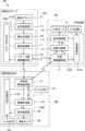
- the ultrasonic system 1 includes an ultrasonic probe 2, a portable information terminal 3, and an external device 4.
- the mobile information terminal 3 and the external device 4 are connected to the ultrasonic probe 2 by wireless communication, and the mobile information terminal 3 and the external device 4 are connected to each other by wireless communication.
- the ultrasonic probe 2 includes an oscillator array 21, and a transmission / reception circuit 22, a signal processing unit 23, and a probe-side wireless communication unit 24 are sequentially connected to the oscillator array 21.
- the probe-side wireless communication unit 24 is connected to the mobile information terminal 3 and the external device 4 by wireless communication.
- the signal processing unit 23 constitutes a reception data generation unit.
- the probe control unit 26 is connected to the transmission / reception circuit 22, the signal processing unit 23, and the probe side wireless communication unit 24.
- the probe side processor 27 is composed of the signal processing unit 23, the probe side wireless communication unit 24, and the probe control unit 26.
- the mobile information terminal 3 includes a terminal-side wireless communication unit 31 connected to the ultrasonic probe 2 and the external device 4 by wireless communication, and the image processing unit 32 is connected to the terminal-side wireless communication unit 31. Further, the mobile information terminal 3 includes a camera unit 33, and the camera unit 33 is connected to the terminal side wireless communication unit 31. Further, the image synchronization unit 34 is connected to the image processing unit 32 and the camera unit 33. Further, the display control unit 35 and the terminal monitor 36 are sequentially connected to the image synchronization unit 34. Further, the terminal control unit 37 is connected to the terminal side wireless communication unit 31, the image processing unit 32, the camera unit 33, the image synchronization unit 34, and the display control unit 35. Further, an input device (terminal input device) 38 is connected to the terminal control unit 37. Further, the terminal side processor 39 is composed of the terminal side wireless communication unit 31, the image processing unit 32, the image synchronization unit 34, the display control unit 35, and the terminal control unit 37.
- the external device 4 includes an external wireless communication unit 41 that is connected to the ultrasonic probe 2 and the mobile information terminal 3 by wireless communication, and the image processing unit 42 and the image synchronization unit 43 are connected to the external wireless communication unit 41. ing. Further, the image processing unit 42 is connected to the image synchronization unit 43. Further, the display control unit 44 and the external monitor 45 are sequentially connected to the image synchronization unit 43. Further, the external control unit 46 is connected to the external wireless communication unit 41, the image processing unit 42, the image synchronization unit 43, and the display control unit 44. Further, an input device (external input device) 47 is connected to the external control unit 46. Further, the external device side processor 48 is composed of the external wireless communication unit 41, the image processing unit 42, the image synchronization unit 43, the display control unit 44, and the external control unit 46.
- the oscillator array 21 of the ultrasonic probe 2 has a plurality of oscillators arranged one-dimensionally or two-dimensionally. Each of these oscillators transmits ultrasonic waves according to the drive signal supplied from the transmission / reception circuit 22, receives ultrasonic echoes from the subject, and outputs a reception signal based on the ultrasonic echoes.
- Each transducer includes, for example, a piezoelectric ceramic represented by PZT (Lead Zirconate Titanate), a polymer piezoelectric element represented by PVDF (PolyVinylidene DiFluoride), and PMN-PT (PMN-PT (polyvinylidene fluoride)).
- piezoelectric material made of a piezoelectric single crystal or the like represented by Lead Magnesium Niobate-Lead Titanate (lead magnesiumidene fluoride-lead titanate solid solution).
- the transmission / reception circuit 22 transmits ultrasonic waves from the oscillator array 21 and generates a sound line signal based on the received signal acquired by the oscillator array 21.
- the transmission / reception circuit 22 includes a pulsar 51 connected to the oscillator array 21, an amplification unit 52 connected in series from the oscillator array 21, an AD (Analog Digital) conversion unit 53, and a beam former. Has 54.
- the pulsar 51 includes, for example, a plurality of pulse generators, and is transmitted from the plurality of oscillators of the oscillator array 21 based on a transmission delay pattern selected according to a control signal from the probe control unit 26.
- Each drive signal is supplied to a plurality of oscillators by adjusting the delay amount so that the ultrasonic waves form an ultrasonic beam.
- a pulsed or continuous wave voltage is applied to the electrodes of the vibrator of the vibrator array 21, the piezoelectric body expands and contracts, and pulsed or continuous wave ultrasonic waves are generated from each vibrator.
- An ultrasonic beam is formed from the combined waves of those ultrasonic waves.
- the transmitted ultrasonic beam is reflected by, for example, a target such as a site of a subject, and propagates toward the vibrator array 21 of the ultrasonic probe 2.
- the ultrasonic echo propagating toward the oscillator array 21 is expanded and contracted by each oscillator constituting the oscillator array 21 by receiving the propagating ultrasonic echo, and the received signal is an electric signal. Is generated, and these received signals are output to the amplification unit 52.
- the amplification unit 52 amplifies the signal input from each of the vibrators constituting the vibrator array 21, and transmits the amplified signal to the AD conversion unit 53.
- the AD conversion unit 53 converts the signal transmitted from the amplification unit 52 into digital reception data, and transmits these reception data to the beam former 54.
- the beam former 54 follows the sound velocity or sound velocity distribution set based on the reception delay pattern selected according to the control signal from the probe control unit 26, and is used for each reception data converted by the AD conversion unit 53.
- the so-called reception focus processing is performed by adding the delays of. By this reception focus processing, each received data converted by the AD conversion unit 53 is phase-adjusted and added, and a sound line signal in which the focus of the ultrasonic echo is narrowed down is acquired.
- the signal processing unit 23 generates reception data before imaging by performing signal processing based on the sound line signal generated by the beam former 54 of the transmission / reception circuit 22. More specifically, the signal processing unit 23 corrects the attenuation due to the propagation distance of the sound line signal generated by the beam former 54 of the transmission / reception circuit 22 according to the depth of the position where the ultrasonic waves are reflected. After that, the envelope detection process is performed to generate a signal representing tomographic image information about the tissue in the subject as the received data before imaging.
- the probe-side wireless communication unit 24 includes an antenna for transmitting and receiving radio waves, and modulates a carrier based on the received data before imaging generated by the signal processing unit 23 to perform the carrier before imaging. Generates a transmission signal that represents received data.
- the probe-side wireless communication unit 24 supplies the transmission signal generated in this way to the antenna and transmits radio waves from the antenna, thereby transmitting the received data before imaging to the terminal-side wireless communication unit 31 of the mobile information terminal 3. And wireless transmission to the external wireless communication unit 41 of the external device 4 in sequence.
- Carrier modulation methods include ASK (Amplitude Shift Keying), PSK (Phase Shift Keying: Phase Shift Keying), QPSK (Quadrature Phase Shift Keying: Quadrature Shift Keying), and 16QAM (16 Quadrature Amplitude). Modulation: 16 quadrature phase amplitude modulation) and the like are used.
- the wireless communication between the probe side wireless communication unit 24 of the ultrasonic probe 2, the terminal side wireless communication unit 31 of the mobile information terminal 3, and the external wireless communication unit 41 of the external device 4 is 5G (5th Generation: 5th generation).
- Mobile communication system communication standards related to mobile communication such as 4G (4th Generation: 4th generation mobile communication system), WiFi (registered trademark), Bluetooth (registered trademark), UWB (Ultra Wide Band: ultra-wideband wireless system), etc. It can be done according to the communication standard for short-range wireless communication.
- the wireless communication between the ultrasonic probe 2 and the mobile information terminal 3 includes mobile communication and short-range wireless communication. Any wireless communication method can be adopted. Further, since the external device 4 is assumed to be located at a remote location with respect to the ultrasonic probe 2 and the mobile information terminal 3, wireless communication between the external device 4 and the ultrasonic probe 2 and the external device 4 It is preferable that mobile communication is performed as wireless communication with the mobile information terminal 3.
- wireless communication between the external device 4 and the ultrasonic probe 2 and mobile communication between the external device 4 and the portable information terminal 3 As wireless communication with the information terminal 3, it is preferable that mobile communication according to 5G is performed.
- the probe control unit 26 controls each unit of the ultrasonic probe 2 based on a control program or the like stored in advance. Further, although not shown, a probe-side storage unit is connected to the probe control unit 26. The probe-side storage unit stores a control program for the ultrasonic probe 2 and the like. Further, as the probe side storage unit, for example, a flash memory, RAM (Random Access Memory), SD card (Secure Digital card), SSD (Solid State Drive) or the like is used. be able to. Further, although not shown, the ultrasonic probe 2 has a built-in battery, and power is supplied from this battery to each circuit of the ultrasonic probe 2.
- the probe-side processor 27 having the signal processing unit 23, the probe-side wireless communication unit 24, and the probe control unit 26 controls the CPU (Central Processing Unit) and the CPU to perform various processes. It consists of programs, but FPGA (Field Programmable Gate Array: Feed Programmable Gate Array), DSP (Digital Signal Processor: Digital Signal Processor), ASIC (Application Specific Integrated Circuit), GPU (Graphics Processing Unit). : Graphics processing unit) and other ICs (Integrated Circuits) may be used, or they may be combined.
- FPGA Field Programmable Gate Array: Feed Programmable Gate Array
- DSP Digital Signal Processor: Digital Signal Processor
- ASIC Application Specific Integrated Circuit
- GPU Graphics Processing Unit
- Graphics processing unit Graphics processing unit
- other ICs Integrated Circuits
- the signal processing unit 23 of the probe-side processor 27, the probe-side wireless communication unit 24, and the probe control unit 26 can be partially or wholly integrated into one CPU or the like.
- the terminal-side wireless communication unit 31 of the mobile information terminal 3 includes an antenna for transmitting and receiving radio waves, and is controlled by the probe-side wireless communication unit 24 of the ultrasonic probe 2 under the control of the terminal control unit 37.
- a transmission signal representing the transmitted received data before imaging is received via an antenna, and the received data before imaging is output by demodulating the received transmission signal. Further, the terminal-side wireless communication unit 31 sends the received data before imaging to the image processing unit 32.
- the image processing unit 32 rasterly converts the received data before imaging transmitted from the terminal-side wireless communication unit 31 into an image signal according to a normal television signal scanning method, and the terminal receives the converted image signal.
- B mode By performing various necessary image processing such as brightness correction, gradation correction, sharpness correction, image size correction, refresh rate correction, scanning frequency correction and color correction according to the display format for the monitor 36.
- Brightness mode Generates an image signal.
- the B-mode image signal generated in this way is simply called an ultrasonic image U. Further, the image processing unit 32 sends the generated ultrasonic image U to the image synchronization unit 34.
- the camera unit 33 acquires a visual field image C that captures the scanning portion of the ultrasonic probe 2 in the subject.
- the camera unit 33 captures a photographing lens, a scanning portion of the ultrasonic probe 2 through the photographing lens, an image sensor that acquires a field image signal that is an analog signal, and a field image acquired by the image sensor.
- It has a built-in analog signal processing circuit that amplifies the signal and converts it into a digital signal, and a digital signal processing circuit that generates a field image C by performing various corrections such as gain on the converted digital signal.
- the analog signal processing circuit and the digital signal processing circuit can also be incorporated in the terminal side processor 39.
- the camera unit 33 sends the generated field of view image C to the terminal-side wireless communication unit 31 and the image synchronization unit 34. Further, the field image C transmitted to the terminal-side wireless communication unit 31 is wirelessly transmitted to the external device 4 by the terminal-side wireless communication unit 31.
- the image synchronization unit 34 synchronizes the ultrasonic image U generated by the image processing unit 32 and the field image C generated by the camera unit 33 with each other, and creates the ultrasonic image U and the field image C synchronized with each other. Based on this, a composite image M is generated.
- synchronizing the ultrasonic image U and the visual field image C with each other means associating the ultrasonic image U and the visual field image C taken at the same timing with each other.
- the image processing unit 32 gives a time stamp indicating the time when the ultrasonic image U is generated to the ultrasonic image U
- the camera unit 33 gives a time stamp indicating the time when the field image C is generated.
- the image synchronization unit 34 When given to the field image C, the image synchronization unit 34 considers the time stamp of the ultrasonic image U to represent the time when the ultrasonic image U was taken, and uses the time stamp of the field image C as the field image. By assuming that C represents the time when the image was taken and referring to the time stamps of the ultrasonic image U and the field image C, the ultrasonic image U and the field image C taken at the same timing are synchronized with each other. be able to.
- the image synchronization unit 34 takes an ultrasonic image U by referring to, for example, the time stamp of the ultrasonic image U and the time stamp of the field image C. If the difference between the time and the time when the field image C is taken is within a certain range, for example, within 0.1 second, it is considered that the ultrasonic image U and the field image C are taken at the same timing. Can be associated. Further, the image synchronization unit 34 refers to, for example, the time stamp of the ultrasonic image U and the time stamp of the field image C, and takes a picture at the time closest to the time when the ultrasonic image U to be associated is taken.
- the image synchronization unit 34 selects, for example, the ultrasonic image U captured at the time closest to the time when the visual field image C to be associated is captured, and sets the ultrasonic image U with the selected ultrasonic image U. It can also be associated with the field image C.
- the image synchronization unit 34 sends the ultrasonic image U and the field image C synchronized in this way to the display control unit 35.
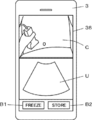
- the display control unit 35 Under the control of the terminal control unit 37, the display control unit 35 performs a predetermined process on the composite image M transmitted from the image synchronization unit 34, and as shown in FIG. 3, the terminal monitor 36 of the mobile information terminal 3 is subjected to predetermined processing. , The synchronized ultrasonic image U and the visual field image C are displayed together. Further, in the example shown in FIG. 3, in addition to the ultrasonic image U and the field image C, a freeze button B1 for freezing the ultrasonic image U and a save button B2 for saving the ultrasonic image U and the field image C Is displayed.
- freezing the ultrasonic image U means suspending the generation of the ultrasonic image U by stopping the transmission of ultrasonic waves from the vibrator array 21.
- the display control unit 35 can display the so-called user interface such as the freeze button B1 and the save button B2 on the terminal monitor 36 under the control of the terminal control unit 37.
- the terminal monitor 36 displays an ultrasonic image U, a field image C, and the like under the control of the display control unit 35.
- an LCD Liquid Crystal Display
- organic EL display Organic Electroluminescence Display
- Etc. including display devices.
- the input device 38 of the mobile information terminal 3 is for the operator to perform an input operation, and includes a touch sensor arranged so as to be superimposed on the terminal monitor 36.
- probe control information for controlling the ultrasonic probe 2 can be input by the operator via the input device 38.
- the probe control information input in this way is transmitted to the terminal side wireless communication unit 31 via the terminal control unit 37, and is wirelessly transmitted from the terminal side wireless communication unit 31 to the ultrasonic probe 2.
- the terminal control unit 37 controls each unit of the mobile information terminal 3 based on a control program or the like stored in advance. Further, although not shown, a terminal side storage unit is connected to the terminal control unit 37.
- the terminal-side storage unit stores a control program or the like of the mobile information terminal 3. Further, as the terminal side storage unit, for example, a flash memory, RAM, SD card, SSD or the like can be used. Further, although not shown, the mobile information terminal 3 has a built-in battery, and power is supplied from this battery to each circuit of the mobile information terminal 3.
- the terminal-side processor 39 having the terminal-side wireless communication unit 31, the image processing unit 32, the image synchronization unit 34, the display control unit 35, and the terminal control unit 37 is for causing the CPU and the CPU to perform various processes. Although it is composed of a control program, it may be configured by using FPGA, DSP, ASIC, GPU, or other IC, or may be configured by combining them. Further, the terminal-side wireless communication unit 31, the image processing unit 32, the image synchronization unit 34, the display control unit 35, and the terminal control unit 37 of the terminal-side processor 39 are partially or wholly integrated into one CPU or the like. It can also be configured.
- the external wireless communication unit 41 of the external device 4 includes an antenna for transmitting and receiving radio waves, and is transmitted by the probe-side wireless communication unit 24 of the ultrasonic probe 2 under the control of the external control unit 46.
- the transmission signal representing the received data before imaging and the transmission signal representing the field image C transmitted by the terminal-side wireless communication unit 31 of the mobile information terminal 3 are received via the antenna, and the received transmission signal is demolished. As a result, the received data before imaging and the field image C are output. Further, the external wireless communication unit 41 sends the received data before imaging to the image processing unit 42, and sends the visual field image C to the image synchronization unit 43.
- the image processing unit 42 rasterly converts the received data before imaging transmitted from the external wireless communication unit 41 into an image signal according to a normal television signal scanning method, and externally monitors the converted image signal.
- An ultrasonic image U is generated by performing various necessary image processing such as brightness correction, gradation correction, sharpness correction, image size correction, refresh rate correction, scanning frequency correction, and color correction according to the display format for 45. ..
- the image processing unit 42 sends the generated ultrasonic image U to the image synchronization unit 43.
- the image synchronization unit 43 of the external device 4 synchronizes the ultrasonic image U transmitted from the image processing unit 42 and the visual field image C transmitted from the external wireless communication unit 41 with each other, and the ultrasonic image U synchronized with each other. And the composite image M is generated based on the field image C.
- the image processing unit 42 of the external device 4 gives a time stamp indicating the time when the ultrasonic image U is generated to the ultrasonic image U, and the camera unit 33 of the mobile information terminal 3 generates the field image C.
- the image synchronization unit 43 considers the time stamp of the ultrasonic image U to represent the time when the ultrasonic image U was taken, and the field of view.
- the time stamp of the image C is regarded as representing the time when the field image C was taken, and by referring to the time stamps of the ultrasonic image U and the field image C, the ultrasonic image U and the ultrasonic image U taken at the same timing
- the field image C can be synchronized with each other.
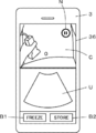
- the display control unit 44 Under the control of the external control unit 46, the display control unit 44 performs a predetermined process on the composite image M transmitted from the image synchronization unit 43, and causes the external monitor 45 of the external device 4 to perform a predetermined process as shown in FIG.
- the synchronized ultrasonic image U and the visual field image C are displayed together.
- the freeze button B1 and the save button B2 are displayed. In this way, the display control unit 44 can display the user interfaces such as the freeze button B1 and the save button B2 on the external monitor 45.
- the external monitor 45 displays the ultrasonic image U, the visual field image C, and the like under the control of the display control unit 44, and includes, for example, a display device such as an LCD or an organic EL display.
- the input device 47 of the external device 4 is for the operator to perform an input operation, and includes a touch sensor arranged so as to be superimposed on the external monitor 45.
- the external control unit 46 controls each unit of the external device 4 based on a control program or the like stored in advance.
- an external device side storage unit is connected to the external device 4.
- the storage unit on the external device side stores a control program or the like of the external device 4.
- a flash memory, RAM, SD card, SSD or the like can be used as the storage unit on the external device side.
- the external device 4 has a built-in battery, and power is supplied from this battery to each circuit of the external device 4.
- the external device side processor 48 having the external wireless communication unit 41, the image processing unit 42, the image synchronization unit 43, the display control unit 44, and the external control unit 46 is for causing the CPU and the CPU to perform various processes. Although it is composed of a control program, it may be configured by using FPGA, DSP, ASIC, GPU, or other IC, or may be configured by combining them. Further, the external wireless communication unit 41, the image processing unit 42, the image synchronization unit 43, the display control unit 44, and the external control unit 46 of the external device side processor 48 are partially or wholly integrated into one CPU or the like. It can also be configured.
- the operator contacts the ultrasonic probe 2 on the body surface of the subject, and under the control of the probe control unit 26, a plurality of oscillator arrays 21 follow the drive signals from the pulsar 51 of the transmission / reception circuit 22.
- An ultrasonic beam is transmitted from the oscillator into the subject.
- the ultrasonic echo based on the transmitted ultrasonic beam is received by each oscillator, the received signal which is an analog signal is output to the amplification unit 52 and amplified, and the AD conversion unit 53 performs AD conversion to acquire the received data. Will be done.
- a sound line signal is generated by performing reception focus processing on the received data by the beam former 54.
- the generated sound line signal is converted by the signal processing unit 23 into received data before imaging, which is a signal representing tomographic image information about the tissue in the subject.
- the signal processing unit 23 corrects the attenuation caused by the propagation distance of the sound line signal according to the depth of the position where the ultrasonic wave is reflected, and then performs the envelope detection process.
- the probe-side wireless communication unit 24 wirelessly transmits the generated sound line signal to the mobile information terminal 3 and the external device 4.
- the terminal-side wireless communication unit 31 of the mobile information terminal 3 receives the received data before imaging wirelessly transmitted from the ultrasonic probe 2 and sends the received received data before imaging to the image processing unit 32. ..
- the image processing unit 32 rasterly converts the received data before imaging transmitted from the terminal-side wireless communication unit 31 into an image signal according to a normal television signal scanning method, and the terminal receives the converted image signal.
- An ultrasonic image U is generated by performing various necessary image processing such as brightness correction, gradation correction, sharpness correction, image size correction, refresh rate correction, scanning frequency correction, and color correction according to the display format for the monitor 36. To do.
- the ultrasonic image U generated in this way is sent to the image synchronization unit 34.
- the camera unit 33 of the mobile information terminal 3 acquires the visual field image C obtained by capturing the scanning portion of the ultrasonic probe 2 in the subject under the control of the terminal control unit 37.
- the operator captures the field image C via the input device 38 of the portable information terminal 3 while pointing the photographing lens of the camera unit 33 toward the scanning portion of the ultrasonic probe 2 in the subject.
- Control information to that effect can be input.
- the control information input to the operator is input to the terminal control unit 37, and the terminal control unit 37 can control the camera unit 33 so as to capture the field image C according to the control information. ..
- the field-of-view image C thus acquired is sent to the terminal-side wireless communication unit 31 and the image synchronization unit 34.
- the image synchronization unit 34 When the image synchronization unit 34 receives the ultrasonic image U from the image processing unit 32 and the field image C from the camera unit 33, the received ultrasonic image U and the field image C are synchronized with each other and synchronized with each other. A composite image M in which the ultrasonic image U and the field image C are combined into one is generated.
- the image processing unit 32 gives a time stamp indicating the time when the ultrasonic image U is generated to the ultrasonic image U
- the camera unit 33 gives a time stamp indicating the time when the field image C is generated.
- the image synchronization unit 34 When given to the field image C, the image synchronization unit 34 considers the time stamp of the ultrasonic image U to represent the time when the ultrasonic image U was taken, and uses the time stamp of the field image C as the field image. Assuming that C represents the time when the image was taken, the ultrasonic image U and the field image C taken at the same timing are associated with each other by referring to the time stamps of the ultrasonic image U and the field image C. Can be done.
- the ultrasonic image U and the visual field image C synchronized with each other by the image synchronization unit 34 are sent to the display control unit 35 as a composite image M.
- the display control unit 35 sends the composite image M to the terminal monitor 36, and as shown in FIG. 3, the ultrasonic image U and the field image are displayed on the terminal monitor 36. Display with C.
- the visual field image C and the ultrasonic image U are displayed above and below the terminal monitor 36, respectively.
- the visual field image C depicts the state in which the ultrasonic probe 2 is in contact with the abdomen of the subject
- the ultrasonic image U depicts the internal tissue of the abdomen of the subject.
- the operator simultaneously obtains the field image C representing the scanning portion of the ultrasonic probe 2 in the subject and the ultrasonic image U corresponding to the field image C.
- the scanning location of the ultrasonic probe 2 in the subject and the tissue in the subject observed thereby can be easily associated and grasped.
- the field image C acquired by the camera unit 33 is wirelessly transmitted from the terminal side wireless communication unit 31 to the external device 4.
- the external wireless communication unit 41 of the external device 4 receives the received data before imaging wirelessly transmitted from the ultrasonic probe 2 and the field image C wirelessly transmitted from the mobile information terminal 3, and receives the received data before imaging.
- the received data is transmitted to the image processing unit 42, and the received field image C is transmitted to the image synchronization unit 43.
- the image processing unit 42 rasterly converts the received data before imaging transmitted from the external wireless communication unit 41 into an image signal according to a normal television signal scanning method, and externally monitors the converted image signal.
- An ultrasonic image U is generated by performing various necessary image processing such as brightness correction, gradation correction, sharpness correction, image size correction, refresh rate correction, scanning frequency correction, and color correction according to the display format for 45. ..
- the image processing unit 42 sends the generated ultrasonic image U to the image synchronization unit 43.
- the image synchronization unit 43 synchronizes the ultrasonic image U transmitted from the image processing unit 42 and the field image C transmitted from the external wireless communication unit 41 with each other, and the ultrasonic image U and the field image C synchronized with each other. Generates a composite image M in which For example, the image processing unit 42 of the external device 4 gives the ultrasonic image U a time stamp indicating the time when the ultrasonic image U was generated, and the camera unit 33 of the mobile information terminal 3 gives the field image C a field image C. When a time stamp representing the generated time is given to the field image C, the image synchronization unit 43 considers the time stamp of the ultrasonic image U to represent the time when the ultrasonic image U was taken.
- the time stamp of the field image C is regarded as representing the time when the field image C was taken, and by referring to the time stamps of the ultrasonic image U and the field image C, the ultrasonic image U taken at the same timing And the field image C can be synchronized with each other. At this time, the time on the portable information terminal 3 and the time on the external device 4 can be shared with each other.
- the time on the mobile information terminal 3 and the time on the external device 4 can be shared with each other. Specifically, for example, the time is shared based on either the mobile information terminal 3 or the external device 4. Can be done. Further, for example, when either the mobile information terminal 3 or the external device 4 is connected to the Internet, it is built in using a communication protocol such as NTP (Network Time Protocol) or NITZ (Network Identity and Time Zone). Clock time may be set.
- NTP Network Time Protocol
- NITZ Network Identity and Time Zone
- the ultrasonic image U and the visual field image C synchronized with each other by the image synchronization unit 43 are sent to the display control unit 44 as a composite image M.
- the display control unit 44 sends the composite image M to the external monitor 45, and as shown in FIG. 4, the ultrasonic image U and the visual field image are displayed on the external monitor 45. Display with C.
- the external device 4 is a portable terminal similar to the mobile information terminal 3, and the field image C and the ultrasonic image U are respectively above and below the terminal monitor 36 of the external device 4. Is displayed.
- the ultrasonic probe 2 is in contact with the visual field image C on the abdomen of the subject.
- the state is visualized, and the internal tissue of the abdomen of the subject is visualized on the ultrasonic image U.
- the field image C and the ultrasonic image U synchronized with each other are displayed on the terminal monitor 36 of the mobile information terminal 3 and the external monitor 45 of the external device 4, respectively, but the terminal monitor 36 and the external monitor 45 display each other. Displays the same field image C and ultrasonic image U almost at the same time. Therefore, for example, even when the external device 4 is located at a remote location with respect to the portable information terminal 3, the observer observing the external monitor 45 is the inspection site where the subject and the operator are located. The visual field image C and the ultrasonic image U captured in the above can be observed in almost real time.
- the input probe freeze is input.
- the instruction is input to the terminal control unit 37.
- the terminal control unit 37 controls the camera unit 33 so as to stop taking the field of view image C, triggered by the input of the probe freeze instruction.
- the terminal-side wireless communication unit 31 wirelessly transmits the probe freeze instruction sent from the terminal control unit 37 to the probe-side wireless communication unit 24 of the ultrasonic probe 2.
- the probe-side wireless communication unit 24 receives the probe freeze instruction wirelessly transmitted from the probe-side wireless communication unit 24, and inputs the received probe freeze instruction to the probe control unit 26.
- the probe control unit 26 controls the transmission / reception circuit 22 so as to stop the transmission of ultrasonic waves from the oscillator array 21 according to the probe freeze instruction, and the transmission of ultrasonic waves from the oscillator array 21 is stopped.
- the ultrasonic probe 2 transmits ultrasonic waves from the oscillator array 21 and the camera unit 33 of the mobile information terminal 3
- the shooting of the field image C is stopped.
- the display of the ultrasonic image U and the field image C is temporarily stopped on the terminal monitor 36 of the mobile information terminal 3, the transmission of ultrasonic waves from the transducer array 21 and the shooting of the field image C by the camera unit 33 are stopped.
- the ultrasonic image U and the visual field image C immediately before the image is displayed.
- the display of the ultrasonic image U and the field image C is temporarily stopped as in the terminal monitor 36 of the mobile information terminal 3, and the ultrasonic waves are transmitted from the transducer array 21 and transmitted.
- the ultrasonic image U and the field image C immediately before the shooting of the field image C by the camera unit 33 is stopped are displayed.
- an observer observing the ultrasonic image U and the visual field image C displayed on the external monitor 45 inputs a probe freeze instruction indicating that the ultrasonic image U is frozen via the input device 47 of the external device 4. Then, the input probe freeze instruction is sent to the external wireless communication unit 41 via the external control unit 46.
- the external wireless communication unit 41 wirelessly transmits a probe freeze instruction to the terminal side wireless communication unit 31 of the mobile information terminal 3.
- the terminal-side wireless communication unit 31 wirelessly transmits the probe freeze instruction wirelessly transmitted by the external wireless communication unit 41 of the external device 4 to the probe-side wireless communication unit 24 of the ultrasonic probe 2, and terminal-controls the probe freeze instruction. Input to unit 37.
- the probe-side wireless communication unit 24 of the ultrasonic probe 2 receives the probe freeze instruction wirelessly transmitted by the terminal-side wireless communication unit 31 of the mobile information terminal 3, and inputs the received probe freeze instruction to the probe control unit 26.
- the probe control unit 26 controls the transmission / reception circuit 22 so as to stop the transmission of ultrasonic waves from the oscillator array 21 in accordance with the probe freeze instruction.
- the terminal control unit 37 controls the camera unit 33 so as to stop taking the visual field image C by using the input of the probe freeze instruction as a trigger.
- the probe freeze instruction is input via the input device 47 of the external device 4
- the ultrasonic probe 2 transmits ultrasonic waves from the vibrator array 21 and the camera unit 33 of the portable information terminal 3 transmits the ultrasonic waves.
- Shooting of the field image C is stopped.
- the display of the ultrasonic image U and the field image C is temporarily stopped on the terminal monitor 36 of the mobile information terminal 3, the transmission of ultrasonic waves from the transducer array 21 and the shooting of the field image C by the camera unit 33 are stopped.
- the ultrasonic image U and the visual field image C immediately before the image is displayed.
- the display of the ultrasonic image U and the field image C is temporarily stopped as in the terminal monitor 36 of the mobile information terminal 3, and the ultrasonic waves are transmitted from the transducer array 21 and transmitted.
- the ultrasonic image U and the field image C immediately before the shooting of the field image C by the camera unit 33 is stopped are displayed.
- an ultrasonic image is taken in a remote place outside the hospital, such as at home nursing
- the operator who operates the ultrasonic probe to take the ultrasonic image and the photographed ultrasonic image are observed. Observers such as doctors making the diagnosis may differ from each other.
- the operator usually needs to operate the ultrasonic probe while checking the obtained ultrasonic image by himself / herself to take an ultrasonic image of a target site in the subject.
- the skill level of the operator is low, it may be difficult for the operator to determine whether or not the target site of the subject can be accurately observed.
- an operator with a low skill level may not be able to operate the ultrasonic probe by using an appropriate technique, and an ultrasonic image with low image quality may be obtained.
- the observer located at a remote location with respect to the subject and the operator will confirm the ultrasonic image taken by the operator of the ultrasonic diagnostic apparatus to make a diagnosis, but the operator will perform the ultrasonic image. Since it is not possible to grasp how to shoot the ultrasound image, it is accurate whether or not the captured ultrasound image was taken by an appropriate procedure, especially when the ultrasonic image was taken by an operator with low skill. It was sometimes difficult to judge.
- the same field image C and ultrasonic image U are displayed on the terminal monitor 36 and the external monitor 45 at almost the same time. Therefore, for example, the external device 4 Even when is located at a remote location with respect to the mobile information terminal 3, the observer observing the external monitor 45 can see the field image C taken at the inspection site where the subject and the operator are located. And the ultrasonic image U can be observed in almost real time. As a result, for example, a highly skilled observer can give advice to the operator in real time, so that even if the operator located at a remote location has a low skill level, the observer can be given advice in real time. An appropriate ultrasonic image U can be obtained, and the accuracy of ultrasonic diagnosis can be improved.
- the ultrasonic system 1 corresponds to a field image C showing a state in which a highly skilled operator operates the ultrasonic probe 2 and a field image C thereof. It is also possible to have the operator confirm the appropriate ultrasonic image U by an observer who is located at a remote location and has a low skill level. As described above, the ultrasonic system 1 according to the first embodiment of the present invention is very useful from the viewpoint of education.
- an observer observing the ultrasonic image U and the visual field image C displayed on the external monitor 45 passes through the input device 47 of the external device 4.
- the transmission of ultrasonic waves from the transducer array 21 of the ultrasonic probe 2 is stopped, and the acquisition of the field image C by the camera unit 33 of the mobile information terminal 3 is stopped, and the mobile information
- the display of the ultrasonic image U and the visual field image C is paused at the same time on the terminal monitor 36 of the terminal 3 and the external monitor 45 of the external device 4.
- the probe freeze instruction input by the observer observing the ultrasonic image U and the field image C displayed on the external monitor 45 via the input device 47 of the external device 4 is sent from the external wireless communication unit 41 to the mobile information terminal.
- wireless transmission is performed to the probe-side wireless communication unit 24 of the ultrasonic probe 2 via the terminal-side wireless communication unit 31 of 3, the method of wirelessly transmitting the probe freeze instruction is not limited to this.
- the external wireless communication unit 41 can wirelessly transmit the probe freeze instruction to both the probe-side wireless communication unit 24 of the ultrasonic probe 2 and the terminal-side wireless communication unit 31 of the mobile information terminal 3.
- the probe freeze instruction received by the probe side wireless communication unit 24 of the ultrasonic probe 2 is input to the probe control unit 26, and the probe control unit 26 is based on the input probe freeze instruction and the oscillator array.
- the transmission / reception circuit 22 is controlled so as to stop the transmission of ultrasonic waves from 21.
- the probe freeze instruction received by the terminal-side wireless communication unit 31 of the mobile information terminal 3 is input to the terminal control unit 37.
- the terminal control unit 37 controls the display control unit 35 so as to suspend the display of the ultrasonic image U and the field image C on the terminal monitor 36 by using the input of the probe freeze instruction as a trigger, and the terminal control unit 37 controls the display control unit 35 of the field image C.
- the camera unit 33 is controlled so as to stop shooting. As a result, the transmission of ultrasonic waves from the transducer array 21 and the acquisition of the field image C by the camera unit 33 are stopped, and the ultrasonic images are displayed on the terminal monitor 36 of the mobile information terminal 3 and the external monitor 45 of the external device 4.
- the display of U and the field image C is paused at the same time.
- the external wireless communication unit 41 can wirelessly transmit the probe freeze instruction only to the probe side wireless communication unit 24 of the ultrasonic probe 2.
- the probe freeze instruction received by the probe-side wireless communication unit 24 is input to the probe control unit 26 and wirelessly transmitted to the terminal-side wireless communication unit 31 of the mobile information terminal 3.
- the probe control unit 26 controls the transmission / reception circuit 22 so as to stop the transmission of ultrasonic waves from the vibrator array 21 according to the input probe freeze instruction.
- the terminal-side wireless communication unit 31 of the mobile information terminal 3 receives the probe freeze instruction wirelessly transmitted by the probe-side wireless communication unit 24 of the ultrasonic probe 2, and transmits the received probe freeze instruction to the terminal control unit 37. input.
- the terminal control unit 37 controls the display control unit 35 so as to suspend the display of the ultrasonic image U and the visual field image C on the terminal monitor 36 triggered by the input of the probe freeze instruction. Further, the terminal control unit 37 controls the camera unit 33 so as to stop taking the visual field image C by using the input of the probe freeze instruction as a trigger.
- the image processing unit 32 of the mobile information terminal 3 and the image processing unit 42 of the external device 4 each give a time stamp to the generated ultrasonic image U.
- the signal processing unit 23 of the ultrasonic probe 2 performed the envelope detection process. It is also possible to add a time stamp to the signal. In this case, for example, the time in the ultrasonic probe 2 and the time in the mobile information terminal 3 are shared with each other, so that the time is generated by the image processing unit 32 of the mobile information terminal 3 based on the time stamped signal.
- the ultrasonic image U and the field image C generated by the camera unit 33 are synchronized with each other, and the ultrasonic image U generated by the image processing unit 42 of the external device 4 and the field image generated by the camera unit 33 are synchronized with each other.
- C can be synchronized with each other.
- the time on the ultrasonic probe 2 and the time on the mobile information terminal 3 can be shared based on, for example, either the ultrasonic probe 2 or the mobile information terminal 3. Further, for example, when either one of the ultrasonic probe 2 and the mobile information terminal 3 is connected to the Internet, the time of the built-in clock may be set using a communication protocol such as NTP or NITZ.
- the method of synchronizing the ultrasonic image U and the visual field image C with each other is not limited to the method using the time stamp described above.
- the imaging timing of the ultrasonic image U by the ultrasonic probe 2 and the imaging timing of the field image C by the camera unit 33 of the mobile information terminal 3 are synchronized.
- the image synchronization unit 34 of the mobile information terminal 3 and The image synchronization unit 43 of the external device 4 considers that the ultrasonic image U and the field image C have been captured at the same timing, and can synchronize the ultrasonic image U and the field image C with each other.
- the image synchronization unit 34 of the mobile information terminal 3 generates a composite image M in which the ultrasonic image U and the visual field image C synchronized with each other are combined into one, and the generated composite image M is displayed in the display control unit 35.
- the ultrasonic image U and the field image C synchronized with each other can be transmitted to the display control unit 35, respectively.
- the display control unit 35 performs predetermined processing on the ultrasonic image U and the visual field image C transmitted from the image synchronization unit 34, and synchronizes with each other on the terminal monitor 36 as shown in FIG.
- the ultrasonic image U and the visual field image C are displayed together. Therefore, the operator can simultaneously confirm the position of the ultrasonic probe 2 and the state of the tissue in the subject corresponding thereto.
- the image synchronization unit 43 of the external device 4 can send the ultrasonic image U and the visual field image C synchronized with each other to the display control unit 44, respectively, instead of generating the composite image M. Also in this case, since the ultrasonic image U and the visual field image C synchronized with each other are simultaneously displayed on the external monitor 45, the observer looking at the external monitor 45 is positioned with the subject and the operator. It is possible to observe the visual field image C and the ultrasonic image U taken at the inspection site in almost real time.
- the ultrasonic probe 2 and the mobile information terminal 3 are connected to each other by wireless communication, for example, instead of the connection by wireless communication, they can be connected to each other by wired communication.
- the external device 4 is a portable thin computer called a so-called smartphone or tablet like the mobile information terminal 3, but the external device 4 is not limited to this.
- a so-called notebook type personal computer, a stationary type personal computer, or the like can be used as the external device 4.
- a second external device having a monitor is installed in the vicinity of the site where the subject is inspected by the operator, and the second external device is used as the ultrasonic probe 2 and the portable information terminal 3. Can also be connected to display the ultrasonic image U and the field image C on the monitor of the second external device.
- the operator can more clearly confirm the ultrasonic image U and the visual field image C, so that the scanning location of the ultrasonic probe 2 in the subject And, the tissue in the observed subject can be more clearly associated and grasped.
- the mobile information terminal 3 is exemplified as a portable thin computer called a so-called smartphone or tablet, but the portable information terminal is not limited to this.
- a terminal device that can be worn on the operator's head can also be used as the mobile information terminal 3.
- a terminal monitor 36 is arranged so as to face the operator's eyes when worn on the head, and a field image C representing a field of view in front of the operator is captured by the camera unit 33. Will be done.
- the operator can indirectly confirm the front field of view by checking the field of view image C displayed on the terminal monitor 36 instead of directly checking the front field of view.
- the operator does not need to hold the mobile information terminal 3 in his / her hand. Therefore, for example, the operator has one hand. It is possible to perform a wider variety of tests, such as performing a procedure of inserting a so-called puncture needle into a subject using the other hand while operating the ultrasonic probe 2 using the ultrasonic probe 2.
- the transmission / reception circuit 22 has a beam former 54 together with the amplification unit 52 and the AD conversion unit 53, but the beam former 54 is not inside the transmission / reception circuit 22 but the transmission / reception circuit 22. It may be arranged between the signal processing unit 23 and the signal processing unit 23. In this case, the beam former 54 can also be configured by the probe-side processor 27.
- the probe freeze instruction is input via the input device 38 of the mobile information terminal 3 and the probe freeze instruction is input via the input device 47 of the external device 4.
- the transmission of ultrasonic waves from the transducer array 21 of the ultrasonic probe 2 and the acquisition of the field image C by the camera unit 33 of the mobile information terminal 3 are stopped.
- the terminal monitor 36 of the mobile information terminal 3 is stopped.
- the instruction information indicating that the probe freeze instruction is input from the input device 38 of the mobile information terminal 3 or the probe freeze instruction is input from the input device 47 of the external device 4.
- Source information can be displayed.
- a probe freeze instruction is input via the input device 47 of the external device 4 by an observer observing the ultrasonic image U and the field image C displayed on the external monitor 45.
- a message K indicating that a probe freeze instruction has been input can be displayed via the input device 47 of the external device 4.
- the message K "remote freeze in progress" is displayed on the terminal monitor 36.
- the external monitor 45 also displays the same message K as the message K displayed on the terminal monitor 36.
- a probe freeze instruction is input by an operator of the ultrasonic probe 2 and the mobile information terminal 3 via the input device 38 of the mobile information terminal 3, although not shown, the terminal monitor 36 of the mobile information terminal 3 is not shown.
- a message K indicating that the probe freeze instruction has been input via the input device 38 of the mobile information terminal 3 such as “during local freeze” is displayed.
- FIG. 6 shows.
- the terminal monitor 36 of the mobile information terminal 3 can display the stop icon N indicating that the probe freeze instruction has been input via the input device 47 of the external device 4.
- the external monitor 45 also displays the same stop icon N as the stop icon N displayed on the terminal monitor 36.
- the terminal monitor 36 of the mobile information terminal 3 is not shown.
- a stop icon different from the stop icon N displayed when the probe freeze instruction is input via the input device 47 of the external device 4 is displayed.
- Examples of such a stop icon include a stop icon having a shape, size, color, or the like different from the stop icon N displayed when a probe freeze instruction is input via the input device 47 of the external device 4. Be done.
- FIG. 7 shows.
- the terminal monitor 36 of the mobile information terminal 3 can display the frame line H indicating that the probe freeze instruction has been input via the input device 47 of the external device 4.
- the external monitor 45 also displays the same frame line H as the frame line H displayed on the terminal monitor 36.
- the terminal monitor 36 of the mobile information terminal 3 is not shown.
- a frame line different from the frame line displayed when the probe freeze instruction is input via the input device 47 of the external device 4 is displayed.
- a border for example, a border having a shape, size, thickness, color, or the like different from the border displayed when the probe freeze instruction is input via the input device 47 of the external device 4. Can be mentioned.
- the probe freeze instruction is input from the input device 38 of the mobile information terminal 3 or the input device 47 of the external device 4.
- the operator of the ultrasonic probe 2 and the mobile information terminal 3 and the observer looking at the external monitor 45 can be viewed from either the mobile information terminal 3 side or the external device 4 side. It is possible to easily grasp whether the probe freeze instruction has been input. In particular, even when the display of the ultrasonic image U and the field image C is suddenly paused on the terminal monitor 36 of the mobile information terminal 3 by inputting the probe freeze instruction via the input device 47 of the external device 4.
- the operator of the ultrasonic probe 2 and the mobile information terminal 3 can easily grasp that the probe freeze instruction has been input via the input device 47 of the external device 4, and for example, the display of the ultrasonic probe is temporarily stopped. Operations such as saving the image U and the field image C can be performed without any confusion.
- the transmission of ultrasonic waves from the transducer array 21 and the acquisition of the field image C by the camera unit 33 are stopped, and the display of the ultrasonic image U and the field image C on the terminal monitor 36 and the external monitor 45 is temporarily stopped.
- the transmission of ultrasonic waves from the transducer array 21 is stopped by the input operation of the operator via the input device 38 of the mobile information terminal 3 and the input operation of the observer via the input device 47 of the external device 4.
- the stop of shooting the field image C by the camera unit 33 is released, and the ultrasonic image U and the field image C can be continuously displayed again on the terminal monitor 36 and the external monitor 45.
- the freeze button displayed on the terminal monitor 36 is displayed.
- the transmission of ultrasonic waves from the transducer array 21 and the camera unit 33 the transmission of ultrasonic waves from the transducer array 21 and the camera unit 33.
- the shooting of the field image C can be stopped, and the display of the ultrasonic image U and the field image C on the terminal monitor 36 and the external monitor 45 can be temporarily stopped.
- the freeze button B1 displayed on the terminal monitor 36 or the freeze displayed on the external monitor 45 is displayed.
- the button B1 is touched again, the stop of the transmission of ultrasonic waves from the transducer array 21 and the stop of the shooting of the field image C by the camera unit 33 are released, and the terminal monitor 36 and the external monitor 45 are superposed.
- the ultrasonic image U and the visual field image C can be continuously displayed again.
- the freeze button B1 displayed on the terminal monitor 36 and the freeze button B1 displayed on the external monitor 45 stop the transmission of ultrasonic waves from the oscillator array 21 and the field image C by the camera unit 33. It can be used as a release button to release the stop of shooting.
- the probe freeze instruction such as the message K shown in FIG. 5 and the stop icon N shown in FIG. 6 is the input device 38 of the mobile information terminal 3 and the input device 47 of the external device 4.
- the instruction information source information indicating which of the above is input
- the instruction information source information displayed on the terminal monitor 36 is touched by the operator, or the external monitor 45 is used.
- the transmission of ultrasonic waves from the transducer array 21 and the stoppage of the capture of the visual field image C by the camera unit 33 are released, and the terminal monitor 36 is released. And the ultrasonic image U and the field image C can be continuously displayed again on the external monitor 45.
- external input information such as a cursor A that can be moved by an observer's input operation via the input device 47 of the external device 4 is transmitted to the external monitor 45 of the external device 4 and the mobile information terminal. It can be displayed on the terminal monitor 36 of 3 at the same time.
- the terminal monitor 36 of the mobile information terminal 3 is moved.
- the displayed cursor A is also moved in the same manner. Thereby, for example, more detailed information sharing can be performed between the operator of the ultrasonic probe 2 and the portable information terminal 3A and the observer located in the vicinity of the external device 4A.
- a highly skilled observer observing the ultrasonic image U and the field image C on the external monitor 45 of the external device 4A may contact the less skilled operator of the ultrasonic probe 2 and the portable information terminal 3A. It is possible to easily support the inspection performed by the operator, such as indicating the position where the ultrasonic probe 2 should be scanned by using the cursor A.
- the cursor A that can be moved by the input operation of the operator via the input device 38 of the mobile information terminal 3 can be simultaneously displayed on the terminal monitor 36 of the mobile information terminal 3 and the external monitor 45 of the external device 4. it can.
- a highly skilled operator can more easily and in detail educate a less skilled observer located in the vicinity of the external device 4A on ultrasonic diagnosis.
- the shape of the cursor A is not limited to the arrow shape, and can have any shape such as a circular shape or a polygonal shape.
- FIG. 9 shows the configuration of the mobile information terminal 3A in the modified example of the first embodiment of the present invention.
- a microphone 61 and a speaker 62 are added, a terminal control unit 37A is provided instead of the terminal control unit 37, and a terminal side processor is provided instead of the terminal side processor 39. It is equipped with a 39A.
- the microphone 61 and the speaker 62 are connected to the terminal side wireless communication unit 31.
- FIG. 10 shows the configuration of the external device 4A in the modified example of the first embodiment of the present invention.
- a microphone 63 and a speaker 64 are added, an external control unit 46A is provided instead of the external control unit 46, and an external device side processor is provided instead of the external device side processor 48. It is equipped with 48A.
- the microphone 63 and the speaker 64 are connected to the external wireless communication unit 41.
- voice data is transmitted and received bidirectionally between the mobile information terminal 3A and the external device 4A.
- the emitted voice is input to the microphone 61 of the mobile information terminal 3A, and the voice data is generated by the microphone 61. Will be generated.
- the generated voice data is wirelessly transmitted from the terminal-side wireless communication unit 31 to the external device 4A.
- the external wireless communication unit 41 of the external device 4A receives the voice data wirelessly transmitted from the mobile information terminal 3A, and transmits the received voice data to the speaker 64.
- the speaker 64 reproduces the voice emitted by the operator of the ultrasonic probe 2 and the portable information terminal 3A based on the voice data received from the external wireless communication unit 41.
- the emitted sound is the external device 4A. It is input to the microphone 63, and audio data is generated by the microphone 63.
- the generated voice data is wirelessly transmitted from the external wireless communication unit 41 to the mobile information terminal 3A.
- the terminal-side wireless communication unit 31 of the mobile information terminal 3A receives the voice data wirelessly transmitted from the external device 4A, and transmits the received voice data to the speaker 62.
- the speaker 62 reproduces the voice emitted by the observer located in the vicinity of the external device 4 based on the voice data received from the terminal-side wireless communication unit 31.
- the voice of the operator input to the microphone 61 of the mobile information terminal 3A can be used as the input operation of the operator.
- the terminal control unit 37A acquires instruction information by analyzing the audio data generated based on the operator's voice by the microphone 61, and the camera unit 33 captures the field image C according to the acquired instruction information. It is possible to control each part of the mobile information terminal 3A, such as starting and stopping shooting.
- the ultrasonic probe 2 can be controlled based on the voice data analyzed by the terminal control unit 37A.
- the voice data analyzed by the terminal control unit 37A is wirelessly transmitted from the terminal side wireless communication unit 31 to the ultrasonic probe 2 as input information from the operator, and is transmitted via the probe side wireless communication unit 24.
- the probe control unit 26 controls each part of the ultrasonic probe 2 based on the input information, for example, transmission start and transmission stop of ultrasonic waves by the vibrator array 21, shooting start and shooting stop of the visual field image C by the camera unit 33, and the like. can do.
- the observer's voice input to the microphone 63 of the external device 4A can be used as the observer's input operation.
- the external control unit 46A acquires instruction information by analyzing the voice data generated based on the observer's voice by the microphone 63, and the camera unit 33 of the portable information terminal 3A follows the acquired instruction information. Control of each part of the portable information terminal 3A such as start and stop of photographing of the field image C, and control of each part of the ultrasonic probe 2 such as start and stop of transmission of ultrasonic waves by the transducer array 21 of the ultrasonic probe 2. You can also do it.
- the ultrasonic probe 2 generates the received data before imaging in which the sound line signal is subjected to the envelope detection processing, and the generated received data before imaging is the mobile information terminal 3 and the mobile information terminal 3.
- the ultrasonic image U is wirelessly transmitted to the external device 4
- the ultrasonic image U is generated by the ultrasonic probe 2, and the generated ultrasonic image U can be wirelessly transmitted to the portable information terminal 3 and the external device 4.
- FIG. 11 shows the configuration of the ultrasonic system 1B according to the second embodiment of the present invention.
- the ultrasonic system 1 is provided with an ultrasonic probe 2A instead of the ultrasonic probe 2 and a portable information terminal 3B instead of the portable information terminal 3.
- An external device 4B is provided instead of the external device 4.
- the image processing unit 71 is added to the ultrasonic probe 2 in the first embodiment, the probe control unit 26B is provided instead of the probe control unit 26, and the probe side processor is provided instead of the probe side processor 27. It is equipped with 27B.
- the image processing unit 71 is connected to the signal processing unit 23.
- the signal processing unit 23 and the image processing unit 71 constitute an ultrasonic image generation unit.
- the probe side wireless communication unit 24 and the probe control unit 26B are connected to the image processing unit 71.
- the image processing unit 32 is removed, the terminal control unit 37B is provided instead of the terminal control unit 37, and the terminal side processor is provided instead of the terminal side processor 39. It is equipped with 39B.
- the image synchronization unit 34 and the camera unit 33 are connected to the terminal side wireless communication unit 31.
- the external device 4B of the first embodiment the image processing unit 42 is removed, the external control unit 46B is provided in place of the external control unit 46, and the external device side processor 48 is replaced by the external device side processor 48. It is equipped with 48B.
- the image processing unit 71 of the ultrasonic probe 2B rasterly converts the signal subjected to the envelope detection processing by the signal processing unit 23 into an image signal according to a normal television signal scanning method, and the converted image signal is subjected to raster conversion. , Brightness correction, gradation correction, sharpness correction, image size correction, refresh rate correction, scanning frequency correction, color correction, and other necessary image processing to display for the terminal monitor 36 of the mobile information terminal 3B. An ultrasonic image U according to the format and an ultrasonic image U according to the format for the external monitor 45 of the external device 4B are generated.
- the image processing unit 71 wirelessly transmits an ultrasonic image U according to the display format for the terminal monitor 36 of the mobile information terminal 3B from the probe side wireless communication unit 24 to the mobile information terminal 3B, and is used for the external monitor 45 of the external device 4B.
- the ultrasonic image U according to the above format is wirelessly transmitted from the probe side wireless communication unit 24 to the external device 4B.
- the terminal-side wireless communication unit 31 of the mobile information terminal 3B receives the ultrasonic image U wirelessly transmitted from the ultrasonic probe 2B, and sends the received ultrasonic image U to the image synchronization unit 34.
- the image synchronization unit 34 synchronizes the ultrasonic image U transmitted from the terminal-side wireless communication unit 31 and the field image C generated by the camera unit 33 with each other, and the ultrasonic image U and the field image C synchronized with each other.
- a composite image M is generated based on.
- the image processing unit 71 of the ultrasonic probe 2B gives a time stamp indicating the time when the ultrasonic image U is generated to the ultrasonic image U
- the camera unit 33 of the mobile information terminal 3B gives the field image C.
- the image synchronization unit 34 determines the ultrasonic image U based on the ultrasonic image U and the time stamp given to the field image C. And the field image C can be synchronized with each other.
- the display control unit 35 After performing a predetermined process on the composite image M generated by the image synchronization unit 34, the display control unit 35 sends the composite image M to the terminal monitor 36, and as shown in FIG. 3, the terminal monitor 36 , The ultrasonic image U and the field image C synchronized with each other are displayed together.
- the external wireless communication unit 41 of the external device 4B receives the ultrasonic image U wirelessly transmitted from the ultrasonic probe 2B and the field image C wirelessly transmitted from the mobile information terminal 3B, and receives the received ultrasonic image U and the field image. C is sent to the image synchronization unit 43.
- the image synchronization unit 43 synchronizes the ultrasonic image U and the visual field image C transmitted from the external wireless communication unit 41 with each other, and generates a composite image M based on the ultrasonic image U and the visual field image C synchronized with each other. To do.
- the display control unit 44 sends the composite image M to the external monitor 45, and as shown in FIG. 4, the external monitor 45 ,
- the ultrasonic image U and the visual field image C synchronized with each other are displayed together.
- the portable information terminal 3 has the image processing unit 32.
- the same field image C and ultrasonic image U are displayed on the terminal monitor 36 and the external monitor 45 substantially at the same time as in the ultrasonic system 1 of the first embodiment in which the external device 4 is provided with the image processing unit 42. .. Therefore, for example, the observer who observes the field image C and the ultrasonic image U by the external device 4B arranged at a remote location can give advice to the operator of the ultrasonic probe 2B and the portable information terminal 3B. Therefore, an appropriate ultrasonic image U can be obtained, and the accuracy of ultrasonic diagnosis can be improved.
- the ultrasonic image U and the visual field image C displayed on the external monitor 45 are observed in the same manner as the ultrasonic system 1 of the first embodiment.
- the observer inputs the probe freeze instruction via the input device 47 of the external device 4B
- the transmission of ultrasonic waves from the transducer array 21 of the ultrasonic probe 2 is stopped and the camera unit 33 of the portable information terminal 3B is stopped.
- the imaging of the field image C is stopped, and the display of the ultrasonic image U and the field image C is paused at the same time on the terminal monitor 36 of the mobile information terminal 3B and the external monitor 45 of the external device 4B.
- the portable information terminal 3 is provided with the image processing unit 32 and the external device 4 is provided with the image processing unit 42.
- the ultrasonic probe 2B is provided with the image processing unit 71
- the portable information terminal 3B and the external device 4B do not need to have the image processing units 32 and 42, respectively, and the portable information terminal 3B and the external device 4B do not need to have the image processing units 32 and 42, respectively.
- the internal configuration of the external device 4B is simplified as compared with the internal configuration of the portable information terminal 3 and the external device 4 in the ultrasonic system 1 of the first embodiment. Therefore, according to the ultrasonic system 1B according to the second embodiment, it is possible to reduce the power consumption and the calculation load of the portable information terminal 3B and the external device 4B as compared with the ultrasonic system 1 of the first embodiment. Is.
- the ultrasonic image U and the visual field image C are synchronized in the mobile information terminal 3 and the external device 4, respectively.
- the ultrasonic image U and the visual field image C are synchronized only in the mobile information terminal 3. It can also be synchronized.
- FIG. 12 shows the configuration of the ultrasonic system 1C according to the third embodiment of the present invention.
- the ultrasonic system 1 includes an ultrasonic probe 2C having the same internal configuration as the ultrasonic probe 2 in the ultrasonic system 1 of the first embodiment shown in FIG. 1, and is provided with a portable information terminal instead of the portable information terminal 3.
- the 3C is provided, and the external device 4C is provided instead of the external device 4.
- the ultrasonic probe 2C is connected only to the mobile information terminal 3C by wireless communication, and the external device 4C is connected only to the mobile information terminal 3C by wireless communication.
- the mobile information terminal 3C is the mobile information terminal 3 according to the first embodiment, in which the terminal control unit 37C is provided instead of the terminal control unit 37, and the terminal side processor 39C is provided instead of the terminal side processor 39. ..
- the image synchronization unit 34 is connected to the terminal side wireless communication unit 31. Further, the camera unit 33 is connected to the image synchronization unit 34.
- the image processing unit 42 and the image synchronization unit 43 are removed, and the external device 4C is provided with the external control unit 46C instead of the external control unit 46, instead of the external device side processor 48. Is provided with an external device side processor 48C.
- the display control unit 44 is connected to the external wireless communication unit 41.
- the probe-side wireless communication unit 24 of the ultrasonic probe 2C wirelessly transmits the received data before imaging, which has been subjected to the envelope detection process by the signal processing unit 23, only to the mobile information terminal 3C.
- the terminal-side wireless communication unit 31 of the mobile information terminal 3C receives the received data before imaging wirelessly transmitted from the ultrasonic probe 2C, and sends the received received data before imaging to the image processing unit 32.
- the image processing unit 32 rasterly converts the received data before imaging transmitted from the terminal-side wireless communication unit 31 into an image signal according to a normal television signal scanning method, and brightens the converted image signal.
- the display format for the terminal monitor 36 of the mobile information terminal 3B by performing various necessary image processing such as correction, gradation correction, sharpness correction, image size correction, refresh rate correction, scanning frequency correction and color correction.
- the ultrasonic image U and the ultrasonic image U according to the format for the external monitor 45 of the external device 4B are generated.
- the image processing unit 32 sends an ultrasonic image U according to the display format for the terminal monitor 36 of the portable information terminal 3B and an ultrasonic image U according to the format for the external monitor 45 of the external device 4B to the image synchronization unit 34.
- the camera unit 33 acquires a visual field image C that captures the scanning portion of the ultrasonic probe 2C in the subject, and sends the acquired visual field image C to the image synchronization unit 34.
- the image synchronization unit 34 synchronizes the ultrasonic image U transmitted from the image processing unit 32 and the field image C transmitted from the camera unit 33 with each other. More specifically, the image synchronization unit 34 synchronizes the ultrasonic image U and the field image C according to the display format for the terminal monitor 36 of the mobile information terminal 3B with each other to generate a composite image M, and further, an external device.
- the ultrasonic image U and the field image C according to the display format for the external monitor 45 of 4C are synchronized with each other to generate the composite image M.
- the image synchronization unit 34 sends a composite image M generated based on the ultrasonic image U and the visual field image C according to the display format for the terminal monitor 36 of the portable information terminal 3B synchronized with each other to the display control unit 35. To do.
- the display control unit 35 performs a predetermined process on the composite image M sent from the image synchronization unit 34, then sends the composite image M to the terminal monitor 36, and as shown in FIG. 3, the terminal monitor 36 , The ultrasonic image U and the field image C synchronized with each other are displayed together. Further, the image synchronization unit 34 transmits the ultrasonic image U according to the display format for the external monitor 45 of the external device 4C and the composite image M generated based on the field image C to the terminal side wireless communication unit 31.
- the terminal-side wireless communication unit 31 wirelessly transmits the composite image M transmitted from the image synchronization unit 34 to the external device 4C.
- the external wireless communication unit 41 of the external device 4C receives the composite image M wirelessly transmitted from the mobile information terminal 3C, and sends the received composite image M to the display control unit 44.
- the display control unit 44 performs a predetermined process on the composite image M sent from the external wireless communication unit 41, then sends the composite image M to the external monitor 45, and as shown in FIG. 4, the external monitor 45 In, the ultrasonic image U and the visual field image C synchronized with each other are displayed together.
- the probe freeze instruction input via the input device 47 of the external device 4C by the observer observing the ultrasonic image U and the field image C displayed on the external monitor 45 is sent to the outside via the external control unit 46C. It is sent to the wireless communication unit 41.
- the external wireless communication unit 41 wirelessly transmits the probe freeze instruction only to the terminal-side wireless communication unit 31 of the mobile information terminal 3C.
- the terminal-side wireless communication unit 31 inputs the probe freeze instruction wirelessly transmitted from the external wireless communication unit 41 of the external device 4C to the terminal control unit 37C and wirelessly transmits the probe freeze instruction to the probe control unit 26 of the ultrasonic probe 2C.
- the terminal control unit 37C of the mobile information terminal 3C controls the camera unit 33 so as to stop the generation of the visual field image C when the probe freeze instruction is input as a trigger. Further, the probe-side wireless communication unit 24 of the ultrasonic probe 2C inputs a probe freeze instruction wirelessly transmitted by the terminal-side wireless communication unit 31 of the mobile information terminal 3C to the probe control unit 26. The probe control unit 26 controls the transmission / reception circuit 22 so as to stop the transmission of ultrasonic waves from the vibrator array 21 according to the input probe freeze instruction.
- the ultrasonic system 1C even when the image processing unit 32 and the image synchronization unit 34 are provided only in the mobile information terminal 3C, the mobile information terminal 3 Is provided with the image processing unit 32 and the external device 4 is provided with the image processing unit 42. Similar to the ultrasonic system 1 of the first embodiment, the terminal monitor 36 and the external monitor 45 are substantially the same field image C and ultrasonic image at the same time. U is displayed. Therefore, for example, the observer who observes the field image C and the ultrasonic image U by the external device 4C arranged at a remote location can give advice to the operator of the ultrasonic probe 2C and the portable information terminal 3C. Therefore, an appropriate ultrasonic image U can be obtained, and the accuracy of ultrasonic diagnosis can be improved.
- the ultrasonic image U and the visual field image C displayed on the external monitor 45 are observed in the same manner as the ultrasonic system 1 of the first embodiment.
- the observer inputs the probe freeze instruction via the input device 47 of the external device 4C
- the transmission of ultrasonic waves from the transducer array 21 of the ultrasonic probe 2 is stopped, and the camera unit 33 of the portable information terminal 3C
- the imaging of the field image C is stopped, and the display of the ultrasonic image U and the field image C is paused at the same time on the terminal monitor 36 of the mobile information terminal 3C and the external monitor 45 of the external device 4C.
- the external device 4 is provided with an image processing unit 42 and an image synchronization unit 43, but the ultrasonic system 1C according to the third embodiment is portable. Since the composite image M generated from the information terminal 3C based on the ultrasonic image U and the field image C is wirelessly transmitted to the external device 4C, the external device 4C does not need to have the image processing unit 42 and the image synchronization unit 43.
- the internal configuration of the external device 4C is simpler than the internal configuration of the external device 4 in the first embodiment. Therefore, according to the ultrasonic system 1C according to the third embodiment, it is possible to reduce the power consumption and the calculation load of the external device 4C.
- the display of the ultrasonic image U and the field image C on the external monitor 45 of the external device 4C and the terminal monitor 36 of the mobile information terminal 3C was temporarily stopped by inputting the probe freeze instruction via the input device 47 of the external device 4C.
- the timing at which the display of the ultrasonic image U and the visual field image C is temporarily stopped on the external monitor 45 and the ultrasonic image on the terminal monitor 36 There may be a discrepancy between U and the timing at which the display of the field image C is paused.
- the ultrasonic image U and the visual field image C in the past for several frames with respect to the ultrasonic image U and the visual field image C displayed in the paused state on the terminal monitor 36 are paused on the external monitor 45. It may be displayed in the state.
- the ultrasonic image U and the field image C displayed in the paused state on the terminal monitor 36 and the ultrasonic image U and the field image C displayed in the paused state on the external monitor 45 are displayed.
- the ultrasonic image U and the field image C displayed in the paused state on the terminal monitor 36 and the external monitor 45 can be continuously displayed as they are, assuming that they are substantially the same image.
- the mobile information terminal 3C is provided with a memory (not shown) for storing the ultrasonic image U synchronized with each other and the composite image M generated based on the field image C, and the external monitor 45 pauses from this memory. It is also possible to call up the same ultrasonic image U and visual field image C as the ultrasonic image U and visual field image C displayed in the state and display them on the terminal monitor 36.
- an ultrasonic probe 2 a mobile information terminal 3, and an external device 4 are connected to each other by wireless communication using a so-called 5G (5th Generation) 5th generation mobile communication system, and ultrasonic waves are generated on the terminal monitor 36 and the external monitor 45.
- 5G (5th Generation) 5th generation mobile communication system a so-called 5G (5th Generation) 5th generation mobile communication system
- ultrasonic waves are generated on the terminal monitor 36 and the external monitor 45.
- the frame rate for displaying the image U and the field image C is 30 Hz
- the time required for transmitting and receiving the probe freeze instruction between the ultrasonic probe 2, the personal digital assistant 3C, and the external device 4C is about 1 ms or less.
- the ultrasonic image U and the field image C displayed in the paused state on the external monitor 45 are wirelessly transmitted from the external wireless communication unit 41 to the terminal side wireless communication unit 31 of the mobile information terminal 3C to perform external wireless communication.
- the ultrasonic image U and the field image C wirelessly transmitted from the communication unit 41 can also be displayed on the terminal monitor 36 via the display control unit 35 of the mobile information terminal 3C.
- the same ultrasonic image U and field image C can be displayed on the terminal monitor 36 and the external monitor 45.
- Embodiment 4 In the third embodiment, the received data before imaging, which has been subjected to the envelope detection process by the signal processing unit 23 of the ultrasonic probe 2, is wirelessly transmitted to the mobile information terminal 3 and the external device 4, but the ultrasonic probe 2 An ultrasonic image U can also be generated in.
- FIG. 13 shows the configuration of the ultrasonic system 1D according to the fourth embodiment of the present invention.
- the ultrasonic system 1D is provided with an ultrasonic probe 2D instead of the ultrasonic probe 2C, and is provided with a portable information terminal 3D instead of the portable information terminal 3C.
- An external device 4D is provided instead of the external device 4C.
- the ultrasonic probe 2D is connected only to the mobile information terminal 3D by wireless communication, and the external device 4D is connected only to the mobile information terminal 3D by wireless communication.
- the image processing unit 81 is added to the ultrasonic probe 2C according to the third embodiment, the probe control unit 26D is provided instead of the probe control unit 26, and the probe side processor is provided instead of the probe side processor 27. It is equipped with 27D.
- the image processing unit 81 is connected to the signal processing unit 23, and the probe-side wireless communication unit 24 and the probe control unit 26D are connected to the image processing unit 81.
- the signal processing unit 23 and the image processing unit 81 constitute an ultrasonic image generation unit.
- the image processing unit 32 is removed, the terminal control unit 37D is provided instead of the terminal control unit 37C, and the terminal side processor is provided instead of the terminal side processor 39C. It is equipped with a 39D.
- the image synchronization unit 34 is connected to the terminal side wireless communication unit 31. Further, the camera unit 33 is connected to the image synchronization unit 34.
- the external device 4D is the external device 4C according to the third embodiment, in which the external control unit 46D is provided instead of the external control unit 46C, and the external device side processor 48D is provided instead of the external device side processor 48C. ..
- the image processing unit 81 of the ultrasonic probe 2D rasterly converts the signal subjected to the envelope detection processing by the signal processing unit 23 into an image signal according to a normal television signal scanning method, and the converted image signal is subjected to raster conversion. , Brightness correction, gradation correction, sharpness correction, image size correction, refresh rate correction, scanning frequency correction, color correction, and other necessary image processing to display for the terminal monitor 36 of the mobile information terminal 3D. An ultrasonic image U according to the format and an ultrasonic image U according to the format for the external monitor 45 of the external device 4D are generated. Further, the image processing unit 81 sends the generated ultrasonic image U to the probe side wireless communication unit 24.
- the probe-side wireless communication unit 24 wirelessly transmits the ultrasonic image U transmitted from the image processing unit 81 to the mobile information terminal 3D.
- the terminal-side wireless communication unit 31 receives the ultrasonic image U wirelessly transmitted from the ultrasonic probe 2D, and sends the received ultrasonic image U to the image synchronization unit 34.
- the camera unit 33 acquires a visual field image C that captures the scanning portion of the ultrasonic probe 2D in the subject, and sends the acquired visual field image C to the image synchronization unit 34.
- the image synchronization unit 34 synchronizes the ultrasonic image U transmitted from the terminal-side wireless communication unit 31 and the visual field image C transmitted from the camera unit 33 with each other, and creates the ultrasonic image U and the visual field image C synchronized with each other. Based on this, a composite image M is generated. Specifically, the image synchronization unit 34 synchronizes the ultrasonic image U and the field image C according to the format for the terminal monitor 36 of the mobile information terminal 3D with each other, and further follows the format for the external monitor 45 of the external device 4D. The ultrasonic image U and the visual field image C are synchronized with each other.
- the image synchronization unit 34 sends a composite image M generated based on the ultrasonic image U and the field image C according to the format for the terminal monitor 36 synchronized with each other to the display control unit 35.
- the display control unit 35 performs a predetermined process on the composite image M sent from the image synchronization unit 34, then sends the composite image M to the terminal monitor 36, and as shown in FIG. 3, the terminal monitor 36 , The ultrasonic image U and the field image C synchronized with each other are displayed together.
- the image synchronization unit 34 sends a composite image M generated based on the ultrasonic image U and the field image C according to the format for the external monitor 45 synchronized with each other to the terminal side wireless communication unit 31.
- the terminal-side wireless communication unit 31 wirelessly transmits the composite image M transmitted from the image synchronization unit 34 to the external device 4D.
- the external wireless communication unit 41 of the external device 4D receives the composite image M wirelessly transmitted from the mobile information terminal 3D, and sends the received composite image M to the display control unit 44.
- the display control unit 44 performs a predetermined process on the composite image M sent from the external wireless communication unit 41, then sends the composite image M to the external monitor 45, and as shown in FIG. 4, the external monitor 45 In, the ultrasonic image U and the visual field image C synchronized with each other are displayed together.
- the image processing unit 81 is provided only in the ultrasonic probe 2D, and the image synchronization unit 34 is provided only in the portable information terminal 3D.
- the terminal monitor 36 and the external monitor 45 have the same visual field at almost the same time.
- Image C and ultrasonic image U are displayed. Therefore, for example, an observer who observes the field image C and the ultrasonic image U by an external device 4D arranged at a remote location can give advice to the operator of the ultrasonic probe 2D and the portable information terminal 3D. Therefore, an appropriate ultrasonic image U can be obtained, and the accuracy of ultrasonic diagnosis can be improved.
- the ultrasonic image U and the visual field image C displayed on the external monitor 45 are observed in the same manner as the ultrasonic system 1 of the first embodiment.
- the observer inputs the probe freeze instruction via the input device 47 of the external device 4D
- the transmission of ultrasonic waves from the transducer array 21 of the ultrasonic probe 2 is stopped, and the camera unit 33 of the portable information terminal 3D
- the imaging of the field image C is stopped, and the display of the ultrasonic image U and the field image C is paused at the same time on the terminal monitor 36 of the mobile information terminal 3D and the external monitor 45 of the external device 4D.
- Embodiment 5 In the third embodiment, since the external device 4C receives the composite image M from the mobile information terminal 3C and displays the received composite image M on the external monitor 45, the ultrasonic image U displayed on the external monitor 45. Although the arrangement and size of the visual field image C could not be freely changed on the external device 4C side, it is displayed on the external monitor 45 according to the ultrasonic system 1E of the fifth embodiment shown in FIG. The arrangement and size of the ultrasonic image U and the visual field image C can be arbitrarily changed on the external device 4E side.
- FIG. 14 shows the configuration of the ultrasonic system 1E according to the fifth embodiment of the present invention.
- the ultrasonic system 1E includes an ultrasonic probe 2E having the same internal configuration as the ultrasonic probe 2C in the ultrasonic system 1C of the third embodiment, and is provided with a portable information terminal 3E instead of the mobile information terminal 3C.
- An external device 4E is provided instead of the external device 4C.
- the ultrasonic probe 2E is connected only to the mobile information terminal 3E by wireless communication, and the external device 4E is connected only to the mobile information terminal 3E by wireless communication.
- the mobile information terminal 3E is the mobile information terminal 3C according to the third embodiment, in which the terminal control unit 37E is provided instead of the terminal control unit 37, and the terminal side processor 39E is provided instead of the terminal side processor 39. ..
- the image synchronization unit 34 is connected to the camera unit 33, and the image synchronization unit 34 is connected to the terminal side wireless communication unit 31.
- the external device 4E is the external device 4C according to the third embodiment, in which the external control unit 46E is provided instead of the external control unit 46, and the external device side processor 48E is provided instead of the external device side processor 48. ..
- the probe-side wireless communication unit 24 of the ultrasonic probe 2E wirelessly transmits the received data before imaging that has been subjected to the envelope detection process by the signal processing unit 23 to the mobile information terminal 3E.
- the terminal-side wireless communication unit 31 of the mobile information terminal 3E receives the received data before imaging wirelessly transmitted from the ultrasonic probe 2E, and sends the received received data before imaging to the image processing unit 32.
- the image processing unit 32 has an ultrasonic image U according to the format for the terminal monitor 36 of the mobile information terminal 3E and an external monitor 45 of the external device 4E based on the received data before imaging transmitted from the terminal side wireless communication unit 31. Generates an ultrasonic image U according to the display format for. Further, the image processing unit 32 sends these ultrasonic images U to the image synchronization unit 34.
- the camera unit 33 acquires a visual field image C that captures the scanning portion of the ultrasonic probe 2E in the subject, and sends the acquired visual field image C to the image synchronization unit 34.
- the image synchronization unit 34 synchronizes the ultrasonic image U transmitted from the terminal-side wireless communication unit 31 and the field image C transmitted from the camera unit 33 with each other. Specifically, the image synchronization unit 34 synchronizes the ultrasonic image U and the field image C according to the format for the terminal monitor 36 of the mobile information terminal 3E with each other, and further follows the format for the external monitor 45 of the external device 4E. The ultrasonic image U and the visual field image C are synchronized with each other.
- the image synchronization unit 34 creates the ultrasonic image U and the visual field image C, respectively, without generating one composite image M based on the ultrasonic image U and the visual field image C according to the format for the terminal monitor 36 synchronized with each other. , Is sent to the display control unit 35.
- the display control unit 35 performs predetermined processing on the ultrasonic image U and the visual field image C transmitted from the image synchronization unit 34, and as shown in FIG. 3, the ultrasonic waves synchronized with each other on the terminal monitor 36.
- the image U and the field image C are displayed together.
- the image synchronization unit 34 creates the ultrasonic image U and the visual field image C without generating one composite image M based on the ultrasonic image U and the visual field image C according to the format for the external monitor 45 synchronized with each other.
- Each is sent to the terminal side wireless communication unit 31.
- the terminal-side wireless communication unit 31 wirelessly transmits the ultrasonic image U and the visual field image C transmitted from the image synchronization unit 34 to the external device 4E.
- the external wireless communication unit 41 of the external device 4E receives the ultrasonic image U and the visual field image C wirelessly transmitted from the mobile information terminal 3E, and sends the received ultrasonic image U and the visual field image C to the display control unit 44, respectively. To do.
- the display control unit 44 performs predetermined processing on the ultrasonic image U and the visual field image C transmitted from the external wireless communication unit 41, and the external monitor 45 displays the ultrasonic image U and the visual field image C synchronized with each other. Display together.
- the arrangement and size of the display positions and sizes of the ultrasonic image U and the visual field image C displayed on the external monitor 45 may be adjusted by an observer's input operation via the input device 47. it can.
- the observer inputs instruction information for adjusting the arrangement and size of the ultrasonic image U and the visual field image C on the external monitor 45 via the input device 47
- the input instruction information is input to the external control unit 46E. Is input to the display control unit 44 via.
- the display control unit 44 displays the ultrasonic image U and the visual field image C synchronized with each other based on the input instruction information, for example, by the arrangement and size as shown in FIG.
- the external device 4E, the ultrasonic image U, and the field image C are rotated by 90 degrees as compared with the example shown in FIG. 4, and the field image C is superimposed on a part of the ultrasonic image U.
- the ultrasonic image U and the visual field image C are displayed on the external monitor 45.
- the arrangement and size of the ultrasonic image U and the field image C displayed on the external monitor 45 of the external device 4E can be adjusted.
- An observer observing the ultrasonic image U and the field image C displayed on the monitor 45 can confirm the ultrasonic image U and the field image C more clearly according to his / her preference.
- Embodiment 6 In the fifth embodiment, the received data before imaging, which has been subjected to the envelope detection process by the signal processing unit 23, is wirelessly transmitted to the mobile information terminal 3E by the probe side wireless communication unit 24, but the ultrasonic probe 2 An ultrasonic image U can also be generated in.
- FIG. 16 shows the configuration of the ultrasonic system 1F according to the sixth embodiment of the present invention.
- the ultrasonic system 1F includes an ultrasonic probe 2F instead of the ultrasonic probe 2E, and a mobile information terminal 3F instead of the mobile information terminal 3E.
- the external device 4F is provided instead of the external device 4E.
- the ultrasonic probe 2F is connected only to the mobile information terminal 3F by wireless communication, and the external device 4F is connected only to the mobile information terminal 3F by wireless communication.
- the image processing unit 91 is added to the ultrasonic probe 2E according to the fifth embodiment, the probe control unit 26E is provided instead of the probe control unit 26, and the probe side processor is provided instead of the probe side processor 27. It is equipped with 27E.
- the image processing unit 91 is connected to the signal processing unit 23, and the probe-side wireless communication unit 24 and the probe control unit 26F are connected to the image processing unit 91. Further, although not shown, the signal processing unit 23 and the image processing unit 91 constitute an ultrasonic image generation unit.
- the image processing unit 32 is removed, the terminal control unit 37F is provided instead of the terminal control unit 37E, and the terminal side processor is provided instead of the terminal side processor 39E. It is equipped with 39F.
- the image synchronization unit 34 is connected to the terminal side wireless communication unit 31. Further, the camera unit 33 is connected to the image synchronization unit 34.
- the external device 4F is the external device 4E according to the fifth embodiment, in which the external control unit 46F is provided instead of the external control unit 46E, and the external device side processor 48F is provided instead of the external device side processor 48E. ..
- the image processing unit 91 of the ultrasonic probe 2F raster-converts the signal subjected to the envelope detection processing by the signal processing unit 23 into an image signal according to a normal television signal scanning method, and the converted image signal is subjected to raster conversion. , Brightness correction, gradation correction, sharpness correction, image size correction, refresh rate correction, scanning frequency correction, color correction, and other necessary image processing to display for the terminal monitor 36 on the 3rd floor of the mobile information terminal. An ultrasonic image U according to the format and an ultrasonic image U according to the format for the external monitor 45 of the external device 4F are generated. Further, the image processing unit 91 sends the generated ultrasonic image U to the probe side wireless communication unit 24.
- the terminal-side wireless communication unit 31 receives the ultrasonic image U wirelessly transmitted from the ultrasonic probe 2F, and sends the received ultrasonic image U to the image synchronization unit 34.
- the camera unit 33 acquires a visual field image C that captures the scanning portion of the ultrasonic probe 2F in the subject, and sends the acquired visual field image C to the image synchronization unit 34.
- the image synchronization unit 34 synchronizes the ultrasonic image U transmitted from the terminal-side wireless communication unit 31 and the field image C transmitted from the camera unit 33 with each other. Specifically, the image synchronization unit 34 synchronizes the ultrasonic image U and the field image C according to the format for the terminal monitor 36 of the mobile information terminal 3F with each other, and further follows the format for the external monitor 45 of the external device 4F. The ultrasonic image U and the visual field image C are synchronized with each other.
- the image synchronization unit 34 creates the ultrasonic image U and the visual field image C, respectively, without generating one composite image M based on the ultrasonic image U and the visual field image C according to the format for the terminal monitor 36 synchronized with each other. , Is sent to the display control unit 35.
- the display control unit 35 performs predetermined processing on the ultrasonic image U and the visual field image C transmitted from the image synchronization unit 34, and causes the ultrasonic image U and the visual field image C synchronized with each other on the terminal monitor 36. Display together.
- the image synchronization unit 34 creates the ultrasonic image U and the visual field image C without generating one composite image M based on the ultrasonic image U and the visual field image C according to the format for the external monitor 45 synchronized with each other.
- Each is sent to the terminal side wireless communication unit 31.
- the terminal-side wireless communication unit 31 wirelessly transmits the ultrasonic image U and the visual field image C transmitted from the image synchronization unit 34 to the external device 4F.
- the external wireless communication unit 41 of the external device 4F receives the ultrasonic image U and the visual field image C wirelessly transmitted from the mobile information terminal 3F, and sends the received ultrasonic image U and the visual field image C to the display control unit 44, respectively. To do.
- the display control unit 44 performs predetermined processing on the ultrasonic image U and the visual field image C transmitted from the external wireless communication unit 41, and the ultrasonic image U and the visual field image C synchronized with each other on the external monitor 45. To be displayed together.
- the display control unit 44 can adjust the arrangement and size of the ultrasonic image U and the visual field image C displayed on the external monitor 45 according to the input operation of the observer via the input device 47. As a result, for example, as shown in FIG. 15, the ultrasonic image U and the visual field image C synchronized with each other are displayed together on the external monitor 45.
- the ultrasonic system 1F according to the sixth embodiment of the present invention, even when the ultrasonic probe 2F includes the image processing unit 91, it is displayed on the external monitor 45 of the external device 4F. Since the arrangement and size of the ultrasonic image U and the field image C can be adjusted, the observer observing the ultrasonic image U and the field image C displayed on the external monitor 45 can more clearly superimpose the ultrasonic image U and the field image C according to his / her preference. The ultrasonic image U and the field image C can be confirmed.
- Embodiment 7 In the first embodiment, the ultrasonic image U and the field image C taken by the operator of the ultrasonic probe 2 and the mobile information terminal 3 are displayed in real time on the external monitor 45 of the external device 4, but are being inspected.
- the ultrasonic image U and the field image C captured in the above can be saved, and the saved ultrasonic image U and the field image C can be displayed on the external monitor 45 as so-called thumbnail images.
- FIG. 17 shows the configuration of the external device 4G according to the seventh embodiment of the present invention.
- the ultrasonic system according to the seventh embodiment is the ultrasonic system 1 of the first embodiment shown in FIG. 1 in which the external device 4G shown in FIG. 17 is provided instead of the external device 4, and the ultrasonic probe 2 ,
- the mobile information terminal 3 and the external device 4G are each connected to each other by wireless communication.
- the image memory 101 and the thumbnail image generation unit 102 are added, and the external control unit 46G is provided instead of the external control unit 46.
- the external device side processor 48G is provided instead of the external device side processor 48.
- the image memory 101 is connected to the image synchronization unit 43, and the thumbnail image generation unit 102 is connected to the image memory 101. Further, the display control unit 44 and the external control unit 46G are connected to the thumbnail image generation unit 102.
- the image memory 101 is a memory for storing the ultrasonic image U and the visual field image C synchronized with each other by the image synchronization unit 43.
- the image memory 101 for example, a flash memory, RAM, SD card, SSD, or the like can be used.
- the transmission of ultrasonic waves from the transducer array 21 of the ultrasonic probe 2 and the acquisition of the field image C by the camera unit 33 of the mobile information terminal 3 are stopped, and the terminal monitor 36 of the mobile information terminal 3 and the external device 4G are stopped.
- an instruction to save the ultrasonic image U and the field image C is given to the input device 47 of the external device 4G or the mobile information terminal 3.
- the ultrasonic image U and the visual field image C synchronized with each other can be stored in the image memory 101 by the image synchronization unit 43, triggered by the input via the input device 38 of the above.
- the thumbnail image generation unit 102 generates a thumbnail image TH composed of an ultrasonic image U and a field image C stored in the image memory 101, and monitors the generated thumbnail image TH externally. It is displayed on 45. For example, when the observer inputs instruction information to display the thumbnail image TH on the external monitor 45 via the input device 47 of the external device 4G, the thumbnail image TH is displayed on the external monitor 45. ..
- a plurality of thumbnail images TH composed of ultrasonic images U and field images C synchronized with each other are displayed in a list on the external monitor 45, and are synchronized with each other in the vicinity of the respective thumbnail images TH.
- the date and time DT at which the ultrasonic image U and the field image C were taken are displayed.
- the image synchronization unit 43 each time a probe freeze instruction is input from the input device 47 of the external device 4G and the input device 38 of the mobile information terminal 3, the image synchronization unit 43
- the ultrasonic image U and the field image C synchronized with each other are stored in the image memory 101, and the thumbnail image generation unit 102 creates a thumbnail image TH based on the ultrasonic image U and the field image C stored in the image memory 101. Since the generated and generated thumbnail image TH is displayed on the external monitor 45, for example, an observer looking at the external monitor 45 can check a plurality of thumbnail image THs listed on the external monitor 45. , A plurality of ultrasonic images U and field images C taken during the inspection can be compared and examined to give more appropriate advice to the operators of the ultrasonic probe 2 and the portable information terminal 3. As a result, the accuracy of ultrasonic diagnosis can be improved.
- the ultrasonic image U and the field image C synchronized with each other are stored in the image memory 101 by the image synchronization unit 43.
- the ultrasonic image U and the field image C are images, respectively.
- the composite image M generated based on the ultrasonic image U and the field image C synchronized with each other can be stored in the image memory 101.
- the image memory 101 is included in the external device 4G.
- the mobile information terminal 3 can include the image memory 101, and the external device 4G and the mobile information Both terminals 3 can also include the image memory 101.
- the mobile information terminal 3 includes the image memory 101 instead of the external device 4G including the image memory 101, for example, the ultrasonic image U and the field image C stored in the image memory 101 are the terminals of the mobile information terminal 3. It can be wirelessly transmitted from the side wireless communication unit 31 to the external wireless communication unit 41 of the external device 4G, and further transmitted from the external wireless communication unit 41 to the thumbnail image generation unit 102.
- the observer looking at the external monitor 45 selects one of the plurality of thumbnail images TH displayed on the external monitor 45 via the input device 47 of the external device 4G, and the selected thumbnail image TH is used.
- the corresponding ultrasonic image U and field image C can also be displayed on the external monitor 45 and the terminal monitor 36 of the mobile information terminal 3, as shown in FIGS. 3 and 4.
- the observer looking at the external monitor 45 makes the operator of the ultrasonic probe 2 and the portable information terminal 3 confirm the specific ultrasonic image U and the field image C, and for example, the ultrasonic image U. It is possible to improve the accuracy of ultrasonic diagnosis because it is possible to give instructions and advice for re-imaging of.
- the probe freeze instruction is input by the input device 47 of the external device 4G and the input device 38 of the mobile information terminal 3, and the instruction information to save the ultrasonic image U and the field image C is provided.
- the ultrasonic image U and the field image C are saved in the image memory 101.
- the external device 4G does not input the instruction information to save the ultrasonic image U and the field image C.
- the ultrasonic image U and the field image C can be automatically saved in the image memory 101 only by inputting the probe freeze instruction by the input device 47 and the input device 38 of the mobile information terminal 3. ..
- the observer observing the ultrasonic image U and the field image C displayed on the external monitor 45 and the operator of the ultrasonic probe 2 and the mobile information terminal 3 save the ultrasonic image U and the field image C. Therefore, the number of steps to be performed is reduced, and the ultrasonic image U and the field image C can be more easily stored in the image memory 101.
- the input device 38 of the mobile information terminal 3 and the input device 47 of the external device 4 The instruction information source information indicating through which the probe freeze instruction is input can be displayed on the external monitor 45 in correspondence with each thumbnail image TH.
- instruction information source information a message such as "remote freeze” or "local freeze” may be displayed in the vicinity of the thumbnail image TH, and the shapes, sizes, colors, etc. are different from each other in the vicinity of the thumbnail image TH.
- Two types of icons may be displayed, or two types of borders surrounding the thumbnail image TH, which are different in shape, size, thickness, color, etc., may be displayed.
- the observer looking at the external monitor 45 gives an instruction to freeze the thumbnail image TH displayed on the external monitor 45 via either the input device 38 of the mobile information terminal 3 or the input device 47 of the external device 4.
- the probe freeze instruction is input via the input device 38 of the mobile information terminal 3 or the input device 47 of the external device 4, so that the terminal monitor 36 of the mobile information terminal 3 and the external monitor of the external device 4 are externally monitored.
- the ultrasonic image U and the visual field image C synchronized with each other are displayed in the paused state, but the ultrasonic image U displayed in the paused state by the input operation via the input device 47 of the external device 4.
- the object to be measured refers to an object to be measured, such as a part of a subject included in the ultrasonic image U.
- FIG. 19 shows the configuration of the external device 4H according to the eighth embodiment of the present invention.
- the ultrasonic system according to the eighth embodiment is the ultrasonic system 1 of the first embodiment shown in FIG. 1 in which the external device 4H shown in FIG. 19 is provided instead of the external device 4, and the ultrasonic probe 2 ,
- the mobile information terminal 3 and the external device 4H are connected to each other by wireless communication.
- the measurement unit 111 is added, the external control unit 46H is provided instead of the external control unit 46, and the external device side processor 48 Instead, an external device side processor 48H is provided.
- the measurement unit 111 is connected to the image processing unit 42. Further, the external wireless communication unit 41, the display control unit 44, and the external control unit 46H are connected to the measurement unit 111.
- the measurement unit 111 analyzes the ultrasonic image U generated by the image processing unit 42 and measures the object to be measured in the ultrasonic image U. For example, when an instruction to perform measurement is input by the observer via the input device 47 of the external device 4H, the ultrasonic image U used for the measurement is displayed on the external monitor 45.
- the measuring unit 111 can perform measurement such as measuring the distance between two points in the displayed ultrasonic image U based on the input operation by the observer via the input device 47.
- the process of measurement and the measurement result in this way are displayed on the external monitor 45, and at the same time, they can be displayed on the terminal monitor 36 of the mobile information terminal 3.
- the measurement unit 111 can measure the object to be measured in the ultrasonic image U according to the input operation via the input device 47 of the external device 4H. Therefore, the observer looking at the external monitor 45 can obtain more detailed information about the captured ultrasonic image U. Therefore, for example, based on the obtained information, the ultrasonic probe 2 and the portable device 2 can be carried. More appropriate advice can be given to the operator of the information terminal 3.
- the external device 4H includes the measuring unit 111, and the measurement object in the ultrasonic image U is measured according to the input operation of the observer via the input device 47 of the external device 4H.
- the measurement unit 111 by equipping the mobile information terminal 3 with the measurement unit 111, it is possible to measure the measurement target in the ultrasonic image U according to the input operation of the operator via the input device 38 of the mobile information terminal 3. ..
- the measurement process and the result of the measurement performed by the mobile information terminal 3 can be displayed on the external monitor 45 of the external device 4H.
- the observer looking at the external monitor 45 can give advice to the operator regarding the measurement performed by the operator of the ultrasonic probe 2 and the portable information terminal 3.
- the measurement unit 111 may be provided in the server connected to the mobile information terminal 3 and the external device 4H by a network.
- FIG. 20 shows the configuration of the ultrasonic system 1K according to the modified example of the eighth embodiment of the present invention.
- the ultrasonic probe 2K is connected to the mobile information terminal 3K, and the mobile information terminal 3K and the external device 4K are connected to the server 121 via the network NW.
- the server 121 includes a measuring unit 122.
- the ultrasonic probe 2K, the portable information terminal 3K, and the external device 4K are the same as the ultrasonic probe 2, the mobile information terminal 3, and the external device 4 in the first embodiment, respectively.
- the measurement unit 122 of the server 121 uses the ultrasonic image U displayed on the external monitor 45 as a trigger when the instruction to perform the measurement is input by the observer via the input device 47 of the external device 4K.
- the measurement unit 122 of the server 121 uses the ultrasonic image U displayed on the external monitor 45 as a trigger when the instruction to perform the measurement is input by the observer via the input device 47 of the external device 4K.
- the transmission of ultrasonic waves from the transducer array 21 and the acquisition of the field image C by the camera unit 33 are stopped, and the display of the ultrasonic image U and the field image C on the terminal monitor 36 and the external monitor 45 is temporarily stopped.
- the measurement unit 122 of the server 121 uses the measurement target in the ultrasonic image U as a trigger when an instruction to perform measurement is input by the operator via the input device 38 of the mobile information terminal 3. It is also possible to measure objects.
- the server 121 when the server 121 connected to the mobile information terminal 3K and the external device 4K via the network NW includes the measurement unit 122, the server 121 can be constructed by a computer having high computing power, for example, artificially. It is possible to perform advanced calculations using intelligence (AI: Artificial Intelligence). Therefore, according to the measurement unit 122 of the server 121, for example, a bladder of the subject is included in the ultrasonic image U, and a complicated calculation such as calculating the urine volume in the bladder by calculating the volume thereof is performed. The observer looking at the external monitor 45 obtains more detailed information about the captured ultrasonic image U and informs the operator of the ultrasonic probe 2K and the portable information terminal 3K because it can be easily executed. More appropriate advice can be given to them.
- AI Artificial Intelligence
Landscapes
- Health & Medical Sciences (AREA)
- Life Sciences & Earth Sciences (AREA)
- Engineering & Computer Science (AREA)
- Biomedical Technology (AREA)
- Public Health (AREA)
- General Health & Medical Sciences (AREA)
- Medical Informatics (AREA)
- Surgery (AREA)
- Veterinary Medicine (AREA)
- Heart & Thoracic Surgery (AREA)
- Pathology (AREA)
- Molecular Biology (AREA)
- Physics & Mathematics (AREA)
- Animal Behavior & Ethology (AREA)
- Nuclear Medicine, Radiotherapy & Molecular Imaging (AREA)
- Biophysics (AREA)
- Radiology & Medical Imaging (AREA)
- Computer Networks & Wireless Communication (AREA)
- Gynecology & Obstetrics (AREA)
- Computer Vision & Pattern Recognition (AREA)
- Business, Economics & Management (AREA)
- General Business, Economics & Management (AREA)
- Epidemiology (AREA)
- Primary Health Care (AREA)
- Human Computer Interaction (AREA)
- Ultra Sonic Daignosis Equipment (AREA)
Priority Applications (4)
| Application Number | Priority Date | Filing Date | Title |
|---|---|---|---|
| CN202080057401.4A CN114258287B (zh) | 2019-08-15 | 2020-07-31 | 超声波系统及超声波系统的控制方法 |
| EP20851688.0A EP4014887B1 (en) | 2019-08-15 | 2020-07-31 | Ultrasonic system and control method for ultrasonic system |
| JP2021539205A JP7391974B2 (ja) | 2019-08-15 | 2020-07-31 | 超音波システムおよび超音波システムの制御方法 |
| US17/572,672 US12115021B2 (en) | 2019-08-15 | 2022-01-11 | Ultrasound system and method of controlling ultrasound system |
Applications Claiming Priority (2)
| Application Number | Priority Date | Filing Date | Title |
|---|---|---|---|
| JP2019-149088 | 2019-08-15 | ||
| JP2019149088 | 2019-08-15 |
Related Child Applications (1)
| Application Number | Title | Priority Date | Filing Date |
|---|---|---|---|
| US17/572,672 Continuation US12115021B2 (en) | 2019-08-15 | 2022-01-11 | Ultrasound system and method of controlling ultrasound system |
Publications (1)
| Publication Number | Publication Date |
|---|---|
| WO2021029234A1 true WO2021029234A1 (ja) | 2021-02-18 |
Family
ID=74571058
Family Applications (1)
| Application Number | Title | Priority Date | Filing Date |
|---|---|---|---|
| PCT/JP2020/029424 Ceased WO2021029234A1 (ja) | 2019-08-15 | 2020-07-31 | 超音波システムおよび超音波システムの制御方法 |
Country Status (5)
| Country | Link |
|---|---|
| US (1) | US12115021B2 (https=) |
| EP (1) | EP4014887B1 (https=) |
| JP (1) | JP7391974B2 (https=) |
| CN (1) | CN114258287B (https=) |
| WO (1) | WO2021029234A1 (https=) |
Cited By (5)
| Publication number | Priority date | Publication date | Assignee | Title |
|---|---|---|---|---|
| JP2022129871A (ja) * | 2021-02-25 | 2022-09-06 | コニカミノルタ株式会社 | 超音波画像診断装置、表示制御方法および表示制御プログラム |
| JP2023038507A (ja) * | 2021-09-07 | 2023-03-17 | ルネサスエレクトロニクス株式会社 | 表示制御装置および表示制御方法 |
| JP2023107410A (ja) * | 2022-01-24 | 2023-08-03 | 上田日本無線株式会社 | 超音波診断画像表示装置、超音波画像診断システム及びプログラム |
| US12345411B2 (en) | 2020-06-08 | 2025-07-01 | Sumitomo SHI FW Energia Oy | Arrangement for a method of supporting a side wall of a vertical flue gas pass in a thermal power steam generator |
| JP2025521145A (ja) * | 2022-06-01 | 2025-07-08 | フジフィルム ソノサイト インコーポレイテッド | 端末機の無線ネットワーク接続フィールドをサポートする超音波スキャナ |
Families Citing this family (6)
| Publication number | Priority date | Publication date | Assignee | Title |
|---|---|---|---|---|
| CN112135566B (zh) * | 2018-05-18 | 2024-10-22 | 富士胶片株式会社 | 超声波系统及超声波系统的控制方法 |
| JP7823490B2 (ja) * | 2022-05-06 | 2026-03-04 | コニカミノルタ株式会社 | 超音波診断装置、超音波診断システム及びプログラム |
| JP2023166905A (ja) * | 2022-05-10 | 2023-11-22 | コニカミノルタ株式会社 | 超音波診断装置、超音波診断装置の制御方法及び超音波診断装置の制御プログラム |
| KR102796894B1 (ko) * | 2022-11-11 | 2025-04-17 | (주)휴먼스케이프 | 초음파 영상을 생성하고 편집하는 시스템 |
| JP2024106433A (ja) * | 2023-01-27 | 2024-08-08 | 富士フイルムヘルスケア株式会社 | 超音波情報処理装置、超音波診断システムおよび超音波診断装置 |
| JP2025087469A (ja) * | 2023-11-29 | 2025-06-10 | 富士フイルム株式会社 | 超音波診断システム |
Citations (5)
| Publication number | Priority date | Publication date | Assignee | Title |
|---|---|---|---|---|
| JP2011087729A (ja) * | 2009-10-22 | 2011-05-06 | Aloka Co Ltd | 超音波診断装置 |
| JP2011183056A (ja) | 2010-03-10 | 2011-09-22 | Fujifilm Corp | 超音波診断装置 |
| JP2015053957A (ja) * | 2013-09-10 | 2015-03-23 | 日立アロカメディカル株式会社 | 超音波診断装置 |
| JP2017086360A (ja) | 2015-11-09 | 2017-05-25 | 株式会社日立製作所 | 超音波診断システム |
| US20190038260A1 (en) * | 2016-02-05 | 2019-02-07 | Samsung Electronics Co., Ltd. | Electronic device and operation method thereof |
Family Cites Families (6)
| Publication number | Priority date | Publication date | Assignee | Title |
|---|---|---|---|---|
| US6540679B2 (en) * | 2000-12-28 | 2003-04-01 | Guided Therapy Systems, Inc. | Visual imaging system for ultrasonic probe |
| JP5484658B2 (ja) * | 2007-06-11 | 2014-05-07 | オリンパスメディカルシステムズ株式会社 | 内視鏡装置及び内視鏡画像制御装置 |
| JP6459451B2 (ja) * | 2013-12-12 | 2019-01-30 | コニカミノルタ株式会社 | 超音波診断装置、超音波画像処理方法、及びコンピュータ読み取り可能な非一時的な記録媒体 |
| KR101747305B1 (ko) * | 2014-10-08 | 2017-06-27 | 삼성전자주식회사 | 초음파 진단 장치 및 그에 따른 통신 연결 방법 |
| KR102490069B1 (ko) * | 2015-08-18 | 2023-01-19 | 삼성메디슨 주식회사 | 초음파 진단 장치 및 그 동작방법 |
| CN108289613B (zh) * | 2015-10-22 | 2021-07-06 | 泰拓卡尔有限公司 | 用于生理监测的系统、方法和计算机程序产品 |
-
2020
- 2020-07-31 CN CN202080057401.4A patent/CN114258287B/zh active Active
- 2020-07-31 EP EP20851688.0A patent/EP4014887B1/en active Active
- 2020-07-31 JP JP2021539205A patent/JP7391974B2/ja active Active
- 2020-07-31 WO PCT/JP2020/029424 patent/WO2021029234A1/ja not_active Ceased
-
2022
- 2022-01-11 US US17/572,672 patent/US12115021B2/en active Active
Patent Citations (5)
| Publication number | Priority date | Publication date | Assignee | Title |
|---|---|---|---|---|
| JP2011087729A (ja) * | 2009-10-22 | 2011-05-06 | Aloka Co Ltd | 超音波診断装置 |
| JP2011183056A (ja) | 2010-03-10 | 2011-09-22 | Fujifilm Corp | 超音波診断装置 |
| JP2015053957A (ja) * | 2013-09-10 | 2015-03-23 | 日立アロカメディカル株式会社 | 超音波診断装置 |
| JP2017086360A (ja) | 2015-11-09 | 2017-05-25 | 株式会社日立製作所 | 超音波診断システム |
| US20190038260A1 (en) * | 2016-02-05 | 2019-02-07 | Samsung Electronics Co., Ltd. | Electronic device and operation method thereof |
Non-Patent Citations (1)
| Title |
|---|
| See also references of EP4014887A4 |
Cited By (9)
| Publication number | Priority date | Publication date | Assignee | Title |
|---|---|---|---|---|
| US12345411B2 (en) | 2020-06-08 | 2025-07-01 | Sumitomo SHI FW Energia Oy | Arrangement for a method of supporting a side wall of a vertical flue gas pass in a thermal power steam generator |
| JP2022129871A (ja) * | 2021-02-25 | 2022-09-06 | コニカミノルタ株式会社 | 超音波画像診断装置、表示制御方法および表示制御プログラム |
| JP2023038507A (ja) * | 2021-09-07 | 2023-03-17 | ルネサスエレクトロニクス株式会社 | 表示制御装置および表示制御方法 |
| JP7634450B2 (ja) | 2021-09-07 | 2025-02-21 | ルネサスエレクトロニクス株式会社 | 表示制御装置 |
| JP2023107410A (ja) * | 2022-01-24 | 2023-08-03 | 上田日本無線株式会社 | 超音波診断画像表示装置、超音波画像診断システム及びプログラム |
| JP7693978B2 (ja) | 2022-01-24 | 2025-06-18 | 上田日本無線株式会社 | 超音波診断画像表示装置、超音波画像診断システム及びプログラム |
| JP2025521145A (ja) * | 2022-06-01 | 2025-07-08 | フジフィルム ソノサイト インコーポレイテッド | 端末機の無線ネットワーク接続フィールドをサポートする超音波スキャナ |
| JP7817456B2 (ja) | 2022-06-01 | 2026-02-18 | フジフィルム ソノサイト インコーポレイテッド | 端末機の無線ネットワーク接続フィールドをサポートする超音波スキャナ |
| US12594054B2 (en) | 2022-06-01 | 2026-04-07 | Fujifilm Sonosite, Inc. | Ultrasound scanner that supports handset wireless network connectivity |
Also Published As
| Publication number | Publication date |
|---|---|
| EP4014887A1 (en) | 2022-06-22 |
| US20220125409A1 (en) | 2022-04-28 |
| EP4014887B1 (en) | 2024-10-02 |
| US12115021B2 (en) | 2024-10-15 |
| JPWO2021029234A1 (https=) | 2021-02-18 |
| CN114258287A (zh) | 2022-03-29 |
| JP7391974B2 (ja) | 2023-12-05 |
| EP4014887A4 (en) | 2022-09-28 |
| CN114258287B (zh) | 2025-06-24 |
Similar Documents
| Publication | Publication Date | Title |
|---|---|---|
| JP7391974B2 (ja) | 超音波システムおよび超音波システムの制御方法 | |
| WO2021029180A1 (ja) | 超音波システムおよび超音波システムの制御方法 | |
| JP7811257B2 (ja) | 超音波システムおよび超音波システムの制御方法 | |
| KR101643620B1 (ko) | 초음파 진단 장치 및 초음파 진단 장치의 동작 방법 | |
| JPWO2021029234A5 (https=) | ||
| JP6546078B2 (ja) | 超音波診断システム | |
| WO2022004063A1 (ja) | 超音波診断装置、超音波診断装置の制御方法および超音波診断装置用プロセッサ | |
| JPWO2021029179A5 (https=) | ||
| US12357281B2 (en) | Ultrasound diagnostic apparatus and a control method for an ultrasound diagnostic apparatus in which a B-mode image and an M-mode image generated by an ultrasound probe are wirelessly transmitted to an apparatus main body | |
| JP7821803B2 (ja) | 超音波診断装置および超音波診断装置の制御方法 | |
| JP7817985B2 (ja) | 超音波診断装置および超音波診断装置の制御方法 | |
| JP7854439B2 (ja) | 超音波システムおよび超音波システムの制御方法 | |
| JP7853984B2 (ja) | 超音波診断装置および超音波診断装置の制御方法 |
Legal Events
| Date | Code | Title | Description |
|---|---|---|---|
| 121 | Ep: the epo has been informed by wipo that ep was designated in this application |
Ref document number: 20851688 Country of ref document: EP Kind code of ref document: A1 |
|
| ENP | Entry into the national phase |
Ref document number: 2021539205 Country of ref document: JP Kind code of ref document: A |
|
| NENP | Non-entry into the national phase |
Ref country code: DE |
|
| ENP | Entry into the national phase |
Ref document number: 2020851688 Country of ref document: EP Effective date: 20220315 |
|
| WWG | Wipo information: grant in national office |
Ref document number: 202080057401.4 Country of ref document: CN |