WO2021024888A1 - 水力発電装置用集水装置および水力発電装置 - Google Patents
水力発電装置用集水装置および水力発電装置 Download PDFInfo
- Publication number
- WO2021024888A1 WO2021024888A1 PCT/JP2020/029153 JP2020029153W WO2021024888A1 WO 2021024888 A1 WO2021024888 A1 WO 2021024888A1 JP 2020029153 W JP2020029153 W JP 2020029153W WO 2021024888 A1 WO2021024888 A1 WO 2021024888A1
- Authority
- WO
- WIPO (PCT)
- Prior art keywords
- water
- collecting device
- hydroelectric power
- water collecting
- power generation
- Prior art date
- Legal status (The legal status is an assumption and is not a legal conclusion. Google has not performed a legal analysis and makes no representation as to the accuracy of the status listed.)
- Ceased
Links
Images









Classifications
-
- F—MECHANICAL ENGINEERING; LIGHTING; HEATING; WEAPONS; BLASTING
- F03—MACHINES OR ENGINES FOR LIQUIDS; WIND, SPRING, OR WEIGHT MOTORS; PRODUCING MECHANICAL POWER OR A REACTIVE PROPULSIVE THRUST, NOT OTHERWISE PROVIDED FOR
- F03B—MACHINES OR ENGINES FOR LIQUIDS
- F03B11/00—Parts or details not provided for in, or of interest apart from, the preceding groups, e.g. wear-protection couplings, between turbine and generator
- F03B11/02—Casings
-
- F—MECHANICAL ENGINEERING; LIGHTING; HEATING; WEAPONS; BLASTING
- F03—MACHINES OR ENGINES FOR LIQUIDS; WIND, SPRING, OR WEIGHT MOTORS; PRODUCING MECHANICAL POWER OR A REACTIVE PROPULSIVE THRUST, NOT OTHERWISE PROVIDED FOR
- F03B—MACHINES OR ENGINES FOR LIQUIDS
- F03B7/00—Water wheels
-
- Y—GENERAL TAGGING OF NEW TECHNOLOGICAL DEVELOPMENTS; GENERAL TAGGING OF CROSS-SECTIONAL TECHNOLOGIES SPANNING OVER SEVERAL SECTIONS OF THE IPC; TECHNICAL SUBJECTS COVERED BY FORMER USPC CROSS-REFERENCE ART COLLECTIONS [XRACs] AND DIGESTS
- Y02—TECHNOLOGIES OR APPLICATIONS FOR MITIGATION OR ADAPTATION AGAINST CLIMATE CHANGE
- Y02E—REDUCTION OF GREENHOUSE GAS [GHG] EMISSIONS, RELATED TO ENERGY GENERATION, TRANSMISSION OR DISTRIBUTION
- Y02E10/00—Energy generation through renewable energy sources
- Y02E10/20—Hydro energy
Definitions
- the present invention relates to a hydroelectric power collector and a hydroelectric power generator installed in a water channel, reduces the load required when the water collector is taken in and out of the water channel, and simplifies the water collector in and out of the water channel. Regarding technology.
- a technique has been proposed in which a diffuser casing is provided and a power generator is provided inside the diffuser casing in order to effectively collect and accelerate the kinetic energy of the flow of a water channel or the like (Patent Document 1).
- the pressure in the vicinity of the suction port of the diffuser casing is lower than the pressure in the discharge port, so that the flow velocity in the vicinity of the suction port is collected and accelerated, and the flow velocity in the diffuser casing is increased.
- a water channel has a vertical channel in which water flows in the vertical direction at the bottom of the horizontal channel in which water flows in the horizontal direction, and a hydroelectric power generation facility is arranged below the vertical channel.
- the horizontal flow of water can be turned vertically by an elbow-shaped duct.
- Patent Document 1 uses a power generator provided inside the diffuser casing, and the diffuser casing and the power generator are arranged in a fluid. It is necessary to take out the diffuser casing and the power generator from the flow path at the same time during maintenance of the power generator or when evacuating in an emergency such as heavy rain. At that time, it is necessary to pull up the water in the diffuser casing from the flow path at the same time, and the pulling load becomes large. When the diffuser casing is installed in the water channel while water is flowing in the water channel, the air in the diffuser casing becomes a resistance and a large force is required.
- Patent Document 2 uses an elbow-shaped duct to change the direction of the water flow and prevent the generation of an air suction vortex to prevent the loss of hydraulic energy and the hindrance to the operation of the equipment.
- An object of the present invention is to provide a water collecting device for a hydroelectric power generation device and a hydroelectric power generation device that can be easily installed in a water channel and pulled up from the water channel.
- the water collecting device for a hydroelectric power generation device of the present invention is used in a hydroelectric power generation device including a water turbine wing that is immersed in a water channel and converts hydraulic power into rotational force, and a generator that generates power by the rotation of the water wheel wing. It is installed on the upstream side of the turbine blade and collects water from the water channel on the turbine blade.
- the inflow port opens to a part or the whole of the water channel, the outlet opens toward the turbine blade, and the cross section of the flow path narrows as the inlet approaches the outlet. It has a cylinder. This cylinder is made into one or a plurality of divided bodies that can be separated from the main body of the water collecting device, part of which is the remaining part.
- the water collecting device when the water collecting device is pulled up from the water channel, it can be easily pulled up in a state where one or more divided bodies, the water collecting device main body, etc. are sequentially divided. That is, it is not necessary to pull up the water that fills the space inside the cylinder of the water collecting device, and the water collecting device can be divided into parts and pulled up, so that the pulling load can be reduced.
- the water collecting device When the water collecting device is installed in the water channel, one or a plurality of divided bodies, the water collecting device main body, and the like are individually assembled, so that the water collecting device can be easily installed against the water flowing in the water channel.
- the tubular body has a rectangular cross section having a bottom plate installed on the bottom surface of the water channel, a pair of side plates rising from both side edges of the bottom plate, and a top plate closing the upper edges of the side plates. It may be said. By forming the tubular body into such a rectangular cross section, water in the water channel can be efficiently collected.
- the side plate may have a plurality of side plate divisions as the divisions along the flow path, and may include a frame member that guides each side plate division so as to be movable up and down.
- the slit closing part When there is a risk of flooding such as in an emergency, the slit closing part is slid on the slitted part from the state where the slit is closed to the state where the slit is opened. By simply sliding the slit closing component without pulling it out of the water channel in this way, water can flow from the slit and the water collecting function can be stopped quickly.
- the hydroelectric power generation device of the present invention includes the water turbine blade, the generator, and a water collector for the hydroelectric power generation device of the present invention. Therefore, the above-mentioned effects can be obtained with respect to the water collecting device for the hydroelectric power generation device of the present invention.
- FIG. 8A It is a perspective view of the water collecting device for a hydroelectric power generation device of the third embodiment of this invention. It is a top view which shows the fixing part of the water collecting device. It is sectional drawing of FIG. 8A. It is a top view which shows the bottom plate, the frame member and the like of the water collecting device. It is the figure which looked at the frame member of the water collecting device from the upstream side of a water channel. It is a perspective view which shows the bottom plate, the frame member, the fixing part and the like of the water collecting device. It is a perspective view which shows the bottom plate, the frame member, a plurality of side plate divisions, a fixing component and the like.
- FIGS. 1 to 4A to 4F A water collecting device for a hydroelectric power generation device and a hydroelectric power generation device according to the first embodiment of the present invention will be described with reference to FIGS. 1 to 4A to 4F.
- this hydroelectric power generation device is installed in, for example, a water channel 1 having running water such as a river or an irrigation canal, and generates power by receiving rotation of a water turbine blade 2.
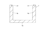
- the water channel 1 is composed of, for example, a bottom surface portion 1a made of concrete or the like and side wall surface portions 1b on both sides.
- the side wall surface portion 1b is perpendicular to the bottom surface portion 1a, but the side wall surface portion 1b may be oblique. Further, the corners of the bottom surface portion 1a and the side wall surface portion 1b are not right-angled as shown in the figure, and the bottom surface portion 1a and the side wall surface portion 1b may be connected by a curved surface, and the bottom surface portion 1a and the side wall surface portion 1b are tapered surfaces. It may be connected.
- the hydroelectric power generation device includes a hydroelectric power generation module 3, a support member 4 for supporting the hydroelectric power generation module 3, and a water collecting device 5 described later.
- the hydroelectric power generation module 3 has a water turbine blade 2 and a generator 6 that generates electricity by the rotation of the water turbine blade 2.
- the turbine blade 2 is installed in a state of being immersed in the running water of the water channel 1 and converts hydraulic power into rotational force.
- the water turbine blade 2 is a propeller type whose center of rotation is parallel to the direction in which flowing water flows.
- the water turbine blade 2 has a hub 2a provided at the center of rotation, and a plurality of (for example, five) blades 2b extending radially outward from the outer peripheral surface of the hub 2a. The tip of each blade 2b is inclined toward the upstream side.
- a rotating shaft (not shown) is rotatably supported coaxially with the hub 2a, and the rotation of the rotating shaft is accelerated by, for example, a gear portion composed of a pair of bevel gears that mesh with each other, and the center of rotation is increased. It is converted from the coaxial direction of the hub 2a to the vertical direction.
- These rotating shafts and gear portions are housed in a gear box.
- the generator 6 is, for example, a permanent magnet synchronous type, an induction type, or other three-phase AC generator, or a single-phase AC generator.
- the input shaft of the generator 6 extends into the support cylinder 7, and in the support cylinder 7, the lower end of the input shaft and the upper end of the power transmission shaft are coaxially connected via a rotary connector (not shown).
- the axis of the power transmission shaft and the axis of the rotation shaft are arranged so as to be orthogonal to each other.
- the power transmission shaft is rotatably supported by the support cylinder 7 by a bearing (not shown) in the support cylinder 7. Therefore, the rotation of the rotating shaft is transmitted to the power transmission shaft and the input shaft, so that the generator 6 generates electricity.
- the support member 4 is two members that are hung and fixed between the upper ends of the wall surfaces 1b on both sides of the water channel 1.
- Each support member 4 is formed of, for example, channel steel.
- the support members 4 and 4 are arranged in parallel at predetermined intervals, and the generator 6 is supported near the middle in the longitudinal direction thereof.
- the support cylinder 7 of the generator 6 extends downward from between the support members 4 and 4.
- the water collecting device 5 is installed on the upstream side of the water turbine blade 2 and collects the water in the water channel 1 in the water turbine blade 2.
- the water collecting device 5 includes a tubular body 8, a plurality of frame members 9, 10 and 11, and a fixing component 12.
- the inflow port opens to a part or the whole of the water channel 1, the outflow port opens toward the turbine blade 2, and the cross section of the flow path (flow path width W) as the inflow port approaches the outflow port.
- the flow path height H) narrows.
- the tubular body 8 is a plurality of divided bodies that can be separated from the main body of the water collecting device, part of which is the remaining portion. In other words, the water collecting function of the water collecting device 5 is satisfied in a state where a plurality of divided bodies are assembled to the water collecting device main body.
- the tubular body 8 has a rectangular cross section having a bottom plate 13 as a main body of the water collecting device, a pair of side plates 14 and 14 which are divided bodies, and a top plate 15 which is a divided body.
- Each component of the cylinder 8 is made of, for example, a plate member made of steel, resin, wood, or the like.
- the bottom plate 13 is installed on the bottom surface of the water channel 1 via frame members 9 and 9 extending in the width direction of the water channel 1, respectively.
- the frame members 9 and 9 are arranged parallel to each other in the water flow direction at predetermined intervals.
- the bottom plate 13 is formed in a trapezoidal shape that becomes narrower as it approaches the outlet from the inlet.
- the application example of the water collecting device main body and the divided body is not limited to the above example.
- a component in which a bottom plate 13 and a pair or one of the side plates 14 are integrally formed may be a water collecting device main body, and the top plate 15 or the top plate 15 and the other side plate 14 may be a divided body. ..
- the bottom plate 13 may be used as the main body of the water collecting device, and the component in which the side plate 14 and the top plate 15 are integrally formed may be used as a divided body.
- one side plate 14 may be used as the main body of the water collecting device, and the remaining parts may be used as the divided body.
- the pair of side plates 14, 14 rise from both side edges of the bottom plate 13 and collect water by narrowing the width of the side surface of the flow path. That is, the side plates 14 and 14 are arranged so as to be inclined with respect to the side wall surface portion 1b so that the distance between the side plates 14 and 14 becomes shorter toward the downstream side. Further, the pair of side plates 14 and 14 are, for example, the same left and right dual-purpose parts, and the upper edge portion of each side plate 14 is formed so that the height gradually decreases from the inflow port to the outflow port.
- a plurality of long frame members 10 extending upward from the vicinity of both ends of the frame members 9 and 9 in the longitudinal direction are provided.
- the side plates 14 on the right side of FIG. 3 are guided up and down to the two frame members 10 and 10 on the right side of FIG. 3, and are detachably attached to one side edge of the bottom plate 13.
- the left side plate 14 of FIG. 3 is guided up and down to the two frame members 10 and 10 on the left side of FIG. 3, and is detachably attached to the other side edge portion of the bottom plate 13.
- the four frame members 10 arranged at both ends in the left and right width directions are fixed to the fixing parts 12 and 12 fixed to the upper ends of the side wall surfaces 1b.
- the top plate 15 is a component that narrows the height of the upper surface of the flow path to collect water, and closes the upper edges of the pair of side plates 14, 14. That is, the upper surface plate 15 is arranged so as to be inclined with respect to the bottom surface portion 1a so that the height H becomes smaller toward the downstream side.
- the top plate 15 is formed in a trapezoidal shape that becomes narrower as it approaches the outlet from the inlet.
- a plurality of (four in this example) short frame members 11 extending downward are provided at the four corners of the top plate 15. By guiding the short frame member 11 up and down to the plurality of long frame members 10, the top plate 15 is detachably assembled to the upper edges of the pair of side plates 14, 14.
- FIGS. 4A to 4F are diagrams showing a stepwise installation example of a water collecting device of a hydroelectric power generation device.
- the divided parts are installed in the order of FIGS. 4A to 4F on the bottom plate 13 installed on the bottom surface of the water channel 1.
- FIG. 4A A bottom plate 13 is installed on the bottom surface of the water channel 1, and a plurality of long frame members 10 are provided as described above.
- FIG. 4B The side plate 14 is guided up and down by the frame member 10.
- FIG. 4C Installation of the side plate 14 is completed.
- FIG. 4D Installation of the top plate 15 provided with the short frame member 11 is started.
- FIG. 4E The top plate 15 is being installed.
- FIG. 4F Installation of the water collecting device 5 is completed.
- the water collecting device 5 is pulled up for each part in the reverse order of FIGS. 4A to 4F, for example. However, a plurality of parts may be pulled up together. All the parts may be pulled up from the water channel 1, or some parts, for example, the bottom plate 13 and the plurality of frame members 10, or the bottom plate 13, the plurality of frame members 10 and the side plates 14 may be pulled up from the water channel 1. You may leave it in.
- the plurality of divided bodies, the water collecting device main body, and the like can be easily pulled up in a state of being sequentially divided. That is, it is not necessary to pull up the water that fills the space inside the cylinder of the water collecting device 5, and the water collecting device 5 can be divided into parts and pulled up, so that the pulling load can be reduced.
- the water collecting device 5 is installed in the water channel 1, since a plurality of divided bodies, the water collecting device main body, and the like are individually assembled, the water collecting device 5 can be easily installed against the water flowing in the water channel 1.
- the tubular body 8 into a rectangular shape as described above, the water in the water channel 1 can be efficiently collected.
- the side plate 14 may have a structure having a slit-attached part 14a formed with a slit St for passing water in the water channel 1 and a slit closing part 14b for closing the slit St.
- a slit-attached part 14a formed with a slit St for passing water in the water channel 1
- a slit closing part 14b for closing the slit St.
- half of the water channel 1 is omitted in order to make it easier to see the water collecting device 5 having the slit St.
- a plurality of slits St are formed in a grid pattern on the slitted component 14a.
- the slit closing component 15b can be manually slid back and forth on the slitted component 14a in a state of closing the slit St (FIG. 5) and a state of opening the slit St (FIG. 6).
- the slit closing component 14b is formed with a plurality of through holes 14ba communicating with the plurality of slits St in a state of being slid forward on the slit-equipped component 14a.
- the slit closing component 14b can hold the state of closing the slit St (FIG. 5) and the state of opening the slit St (FIG. 6) when immersed in the water channel 1.
- the water in the water channel 1 can be efficiently collected by holding the slit closing part 14b in a state of closing the slit St on the slitted part 14a.
- the slit closing part 14b is slid on the slitted part 14a from the state of closing the slit St to the state of opening the slit St.
- it has the same effect as that of the first embodiment described above.
- the side plate 14 has a side plate dividing body 14c divided into a plurality of pieces along the flow path, and each side plate dividing body 14c is provided with a frame member 16 that can move up and down.
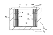
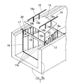
- FIGS. 8A and 8B show sequentially an installation example of the water collecting device 5 provided with the plurality of side plate dividing bodies 14c.
- a plurality of (four in this example) first fixing parts 17 are fixed to the upper ends of the side wall surfaces 1b of the water channel 1.
- the first fixing component 17 for example, the first fixing component 17 is fixed to the water channel 1 by fixing by driving a pile or fixing by an anchor bolt.
- the arrow F in FIG. 8A indicates the water flow direction.
- a weight (not shown) is attached to a part of a part in which the bottom plate 13 of the water collecting device and the plurality of frame members 16 for inserting the side plates are integrated. Parts are difficult to flow due to running water.
- two second fixing parts 18 and 18 are erected on the upper ends of the side wall surfaces 1b of the water channel 1. These second fixing parts 18 and 18 are arranged in parallel with a predetermined interval in the water flow direction and are connected to the first fixing part 17.
- a notch 18a into which the top plate fixing component 19 for fixing the top plate 15 (FIG. 7) is inserted is formed at the upper end of each second fixing component 18.
- the second fixing component 18 for fixing the water collecting device 5 in the flow direction of the water channel 1 and the first fixing component 17 are, for example, bolts (FIG. By fixing with (not shown), the water collecting device 5 can be more reliably positioned with respect to the water channel 1.
- each side plate dividing body 14c is supported by a frame member 16 for inserting the side plate, it is not necessary to fix each side plate dividing body 14c with bolts or the like, and the side plate dividing bodies 14c can be inserted and removed. Workability can be improved. Further, each side plate split body 14c is manually inserted and removed using the work component 20.
- the top plate 15 closes the upper edge portion of the plurality of side plate dividing bodies 14c by using a plurality of (two in this example) top plate fixing parts 19.
- 16 and 17 show a state before the top plate 15 is installed, and
- FIG. 7 shows a state where the top plate 15 is installed.
- Each top plate fixing component 19 has a fixed component main body 19a extending along the flow path direction, and a plurality of protruding portions 19b protruding downward from the fixed component main body 19a at predetermined intervals.
- the fixing component main body 19a is inserted into the notch 18a of the second fixing component 18 and fixed.
- the protruding portion 19b protruding from the vicinity of the middle in the longitudinal direction of the fixed component main body 19a is installed so that each tip presses the upper surface of the upper surface plate 15, and the protruding portion 19b protruding from the upstream end of the fixed component main body 19a. Is installed so as to abut on the upstream surface of the second fixing component 18.
- the water collecting device 5 is pulled up for each part in the reverse order of the above, for example.
- the present invention is not limited to the above embodiments, and various additions, changes, or deletions can be made without departing from the gist of the present invention.
- the cylinder of the above embodiment has a shape in which both the flow path width and the flow path height are narrowed from the inflow port to the outflow port, but it is also possible that either the flow path width or the flow path height is narrowed. Good.
- the inflow port of the cylinder may be shaped to open to a part of the water channel. Therefore, such things are also included within the scope of the present invention.
Landscapes
- Engineering & Computer Science (AREA)
- Chemical & Material Sciences (AREA)
- Combustion & Propulsion (AREA)
- Mechanical Engineering (AREA)
- General Engineering & Computer Science (AREA)
- Hydraulic Turbines (AREA)
Abstract
水力発電装置用集水装置(5)は、水路(1)に浸かり水力を回転力に変換する水車翼(2)と、水車翼(2)の回転により発電する発電機(6)とを備えた水力発電装置に用いられ、水路(1)における水車翼(2)の上流側に設置されて水車翼(2)に水路(1)の水を集水する。集水装置(5)は、流入口が水路(1)の全体に開口し流出口が水車翼(2)に向かって開口し流入口から流出口に近づくに従って流路の断面が狭まる筒体(8)を備える。筒体(8)は、一部が残り部分である集水装置本体に対して分離可能な一個または複数の分割体とされている。
Description
この出願は、2019年8月7日出願の特願2019-145407の優先権を主張するものであり、その全体を参照により本願の一部をなすものとして引用する。
この発明は、水路に設置される水力発電装置用集水装置および水力発電装置に関し、集水装置の水路への出し入れ時に必要な荷重を低減し、集水装置の水路への出し入れを簡単にする技術に関する。
水路等の流れの運動エネルギーを効果的に集水し増速させるために、ディフューザケーシングを設け、このディフューザケーシングの内側に動力発生装置を設けた技術が提案されている(特許文献1)。この技術では、ディフューザケーシングの吸入口近傍の圧力が排出口の圧力よりも低下することで、吸入口近傍の流速を集水し増速させ、ディフューザケーシング内の流速を高めている。
立軸バルブ型水車発電設備で、エルボ型ダクトを備えた技術が提案されている(特許文献2)。この技術では、水平方向に水が流れる水平流路の底に縦方向に水が流れる縦流路を有する水路で、縦流路の下方に、水力発電設備が配置される。水平方向の水の流れはエルボ型ダクトにより縦方向に向きを変えられる。エルボ型ダクトの吸入口の天板を、水平流路を流れる水の最低水位よりも低くすることで、吸入口から空気を吸い込むことがなくなり、空気吸込み渦による水力エネルギーの損失および機器の運転への支障を防ぐことができる。
特許文献1は、ディフューザケーシングの内側に動力発生装置を設け、ディフューザケーシングと動力発生装置とを流体内に配置して使用する。動力発生装置のメンテナンス時または大雨などによる緊急時の退避時には、ディフューザケーシングと動力発生装置とを同時に流路から取り出す必要がある。その際、ディフューザケーシング内の水も同時に流路から引き上げる必要があり、引き上げ荷重が大きくなる。水路に水が流れている状態で、ディフューザケーシングを水路へ設置する場合、ディフューザケーシング内の空気が抵抗となり、大きな力が必要となる。
特許文献2は、エルボ型ダクトにより水流の向きを変え、かつ、空気吸込み渦の発生を防止することで水力エネルギーの損失および機器の運転への支障を防いでいる。緊急時またはメンテナンス時などで、エルボ型ダクトを水路から取り出す場合、エルボ型ダクトが完全に水没しているため、エルボ型ダクトの上端が水面より高くなるまで、エルボ型ダクト内の水を引き上げる必要があり、引き上げ荷重が大きくなる。
この発明の目的は、水路への設置および水路からの引き上げを簡単に行うことができる水力発電装置用集水装置および水力発電装置を提供することである。
この発明の水力発電装置用集水装置は、水路に浸かり水力を回転力に変換する水車翼と、この水車翼の回転により発電する発電機とを備えた水力発電装置に用いられ、前記水路における前記水車翼の上流側に設置されて前記水車翼に前記水路の水を集水する。
この水力発電装置用集水装置は、流入口が前記水路の一部または全体に開口し流出口が前記水車翼に向かって開口し前記流入口から前記流出口に近づくに従って流路の断面が狭まる筒体を備えている。この筒体は、一部が残り部分である集水装置本体に対して分離可能な一個または複数の分割体とされている。
この水力発電装置用集水装置は、流入口が前記水路の一部または全体に開口し流出口が前記水車翼に向かって開口し前記流入口から前記流出口に近づくに従って流路の断面が狭まる筒体を備えている。この筒体は、一部が残り部分である集水装置本体に対して分離可能な一個または複数の分割体とされている。
この構成によると、集水装置を水路から引き上げるとき、一個または複数の分割体、集水装置本体等を順次分割した状態で、簡単に引き上げることができる。つまり、集水装置の筒体内の空間を満たす水を引き上げなくてもよく、集水装置を部品単位で分割して引き上げることができるので、引き上げ荷重を小さくすることができる。集水装置を水路に設置するとき、一個または複数の分割体、集水装置本体等を個別に組み付けるので、水路に流れる水に抗して容易に集水装置を設置することができる。
前記筒体は、前記水路の底面に設置される底面板と、この底面板の両側縁部から立ち上がる一対の側面板と、これら側面板の上縁部を塞ぐ上面板と、を有する断面矩形状とされていてもよい。筒体をこのような断面矩形状とすることで、水路の水を効率良く集水することができる。
前記側面板は前記分割体として流路に沿って複数に分割された側面板分割体を有し、前記各側面板分割体を上下に移動可能に案内する枠部材を備えてもよい。このように側面板を複数枚に分割することで、一枚の側面板分割体を設置するのに必要な力または引き抜くのに必要な力を小さくでき、作業効率を高めることができる。
前記複数の分割体の一部として、前記水路の水を通すスリットが形成されたスリット付き部品と、前記スリットを塞ぐスリット塞ぎ部品とを有し、このスリット塞ぎ部品は、前記スリットを塞ぐ状態と前記スリットを開口する状態とに渡って、前記スリット付き部品上でスライド可能としてもよい。通常時には、スリット塞ぎ部品を、スリット付き部品上でスリットを塞ぐ状態に保持することで水路の水を効率良く集水することができる。緊急時など溢水のおそれがある場合、スリット塞ぎ部品を、スリット付き部品上で、スリットを塞ぐ状態からスリットを開口する状態にスライドさせる。このようにスリット塞ぎ部品を水路から引き上げることなくスライドさせるだけで、スリットからの流水を許し、迅速に集水機能を停止することができる。
この発明の水力発電装置は、前記水車翼と、前記発電機と、この発明の水力発電装置用集水装置とを備えている。このため、この発明の水力発電装置用集水装置につき前述した各効果が得られる。
請求の範囲および/または明細書および/または図面に開示された少なくとも2つの構成のどのような組合せも、この発明に含まれる。特に、請求の範囲の各請求項の2つ以上のどのような組合せも、この発明に含まれる。
本発明は、添付の図面を参考にした以下の好適な実施形態の説明からより明瞭に理解されるであろう。しかしながら、実施形態および図面は単なる図示および説明のためのものであり、本発明の範囲を定めるために利用されるべきものではない。本発明の範囲は添付の請求の範囲によって定まる。添付図面において、複数の図面における同一の部品番号は、同一または相当部分を示す。
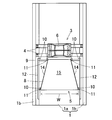
この発明の第1の実施形態に係る水力発電装置の斜視図である。
同水力発電装置の平面図である。
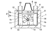
同水力発電装置を水路の上流側から見た図である。
同水力発電装置の集水装置の設置例を段階的に示す図である。
同水力発電装置の集水装置の設置例を段階的に示す図である。
同水力発電装置の集水装置の設置例を段階的に示す図である。
同水力発電装置の集水装置の設置例を段階的に示す図である。
同水力発電装置の集水装置の設置例を段階的に示す図である。
同水力発電装置の集水装置の設置例を段階的に示す図である。
この発明の第2の実施形態に係る水力発電装置の斜視図である。
同水力発電装置の集水装置のスリットを開口した状態を示す斜視図である。
この発明の第3の実施形態の水力発電装置用集水装置の斜視図である。
同集水装置の固定用部品等を示す平面図である。
図8Aの断面図である。
同集水装置の底面板および枠部材等を示す平面図である。
同集水装置の枠部材等を水路の上流側から見た図である。
同集水装置の底面板、枠部材および固定用部品等を示す斜視図である。
同底面板、枠部材、複数の側面板分割体および固定用部品等を示す斜視図である。
同複数の側面板分割体を水路の上流側から見た図である。
同集水装置の片側の側面板を設置した状態を示す斜視図である。
同片側の側面板等を水路の上流側から見た図である。
同集水装置の上面板を設置する前の状態を水路の上流側から見た図である。
同集水装置の上面板を設置する前の斜視図である。
[第1の実施形態]
この発明の第1の実施形態に係る水力発電装置用集水装置および水力発電装置を図1ないし図4A~4Fと共に説明する。
<水力発電装置全体の概略構成>
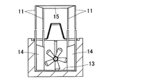
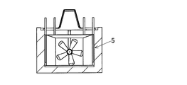
図1~図3に示すように、この水力発電装置は、例えば、河川、用水路等の流水のある水路1に設置され、水車翼2の回転を受けて発電を行う。水路1は、例えば、それぞれコンクリート等から成る底面部1aおよび両側の側壁面部1bで構成される。各図の例では、底面部1aに対して側壁面部1bが垂直になっているが、側壁面部1bは斜めになっていてもよい。また、底面部1aと側壁面部1bの角部が図のような直角状でなく、底面部1aと側壁面部1bとが曲面で繋がっていてもよく底面部1aと側壁面部1bとがテーパ面で繋がっていてもよい。水力発電装置は、水力発電モジュール3と、この水力発電モジュール3を支持する支持部材4と、後述する集水装置5とを備える。
この発明の第1の実施形態に係る水力発電装置用集水装置および水力発電装置を図1ないし図4A~4Fと共に説明する。
<水力発電装置全体の概略構成>
図1~図3に示すように、この水力発電装置は、例えば、河川、用水路等の流水のある水路1に設置され、水車翼2の回転を受けて発電を行う。水路1は、例えば、それぞれコンクリート等から成る底面部1aおよび両側の側壁面部1bで構成される。各図の例では、底面部1aに対して側壁面部1bが垂直になっているが、側壁面部1bは斜めになっていてもよい。また、底面部1aと側壁面部1bの角部が図のような直角状でなく、底面部1aと側壁面部1bとが曲面で繋がっていてもよく底面部1aと側壁面部1bとがテーパ面で繋がっていてもよい。水力発電装置は、水力発電モジュール3と、この水力発電モジュール3を支持する支持部材4と、後述する集水装置5とを備える。
<水力発電モジュール3について>
水力発電モジュール3は、水車翼2、およびこの水車翼2の回転により発電する発電機6を有する。水車翼2は、水路1の流水中に浸かる状態で設置され水力を回転力に変換する。水車翼2は、回転軸心が流水の流れる方向と平行なプロペラ型である。水車翼2は、回転軸心に設けられるハブ2aと、このハブ2aの外周面から半径方向外方に放射状に延びる複数(例えば5枚)のブレード2bとを有する。各ブレード2bの先端部は、上流側に向けて傾斜している。
水力発電モジュール3は、水車翼2、およびこの水車翼2の回転により発電する発電機6を有する。水車翼2は、水路1の流水中に浸かる状態で設置され水力を回転力に変換する。水車翼2は、回転軸心が流水の流れる方向と平行なプロペラ型である。水車翼2は、回転軸心に設けられるハブ2aと、このハブ2aの外周面から半径方向外方に放射状に延びる複数(例えば5枚)のブレード2bとを有する。各ブレード2bの先端部は、上流側に向けて傾斜している。
ハブ2aに同軸に回転軸(図示せず)が回転自在に支持され、この回転軸の回転は、例えば、互いに噛み合う一対の傘歯車等から成るギヤ部により増速され、且つ、回転軸心がハブ2aの同軸方向から上下方向に変換される。これら回転軸およびギヤ部は、ギヤボックス内に収容されている。
発電機6は、例えば、永久磁石同期型、誘導型等の三相交流発電機、または単相交流の発電機である。発電機6の入力軸が支持筒7内に延び、支持筒7内において、前記入力軸の下端と動力伝達軸の上端とが、図示外の回転連結具を介して同軸に連結されている。前記動力伝達軸の軸心と前記回転軸の軸心とは互いに直交するように配置されている。動力伝達軸は、支持筒7内の軸受(図示せず)により、この支持筒7に回転自在に支持されている。したがって、前記回転軸の回転が前記動力伝達軸および前記入力軸に伝達されることで、発電機6が発電する。
支持部材4は、水路1の両側壁面1bの上端間にそれぞれ掛け渡され固定される二つの部材である。各支持部材4は、例えば、溝形鋼から形成される。これら支持部材4,4は、所定間隔を隔てて平行に配置され、これらの長手方向中間付近に発電機6が支持されている。発電機6の支持筒7は、支持部材4,4間から下方に延びる。
<集水装置5について>
集水装置5は、水車翼2の上流側に設置され前記水車翼2に水路1の水を集水する。集水装置5は、筒体8と、複数の枠部材9,10,11と、固定用部品12とを備える。筒体8は、流入口が水路1の一部または全体に開口し、流出口が水車翼2に向かって開口し、前記流入口から前記流出口に近づくに従って流路の断面(流路幅Wおよび流路高さH)が狭まる。この筒体8は、一部が残り部分である集水装置本体に対して分離可能な複数の分割体とされている。換言すれば、集水装置本体に複数の分割体が組み付けられた状態で、集水装置5の集水する機能を満たす。
集水装置5は、水車翼2の上流側に設置され前記水車翼2に水路1の水を集水する。集水装置5は、筒体8と、複数の枠部材9,10,11と、固定用部品12とを備える。筒体8は、流入口が水路1の一部または全体に開口し、流出口が水車翼2に向かって開口し、前記流入口から前記流出口に近づくに従って流路の断面(流路幅Wおよび流路高さH)が狭まる。この筒体8は、一部が残り部分である集水装置本体に対して分離可能な複数の分割体とされている。換言すれば、集水装置本体に複数の分割体が組み付けられた状態で、集水装置5の集水する機能を満たす。
筒体8は、集水装置本体としての底面板13と、分割体である一対の側面板14,14と、分割体である上面板15とを有する断面矩形状とされている。筒体8の各構成部品は、例えば、鋼製、樹脂製または木製等の板部材から成る。底面板13は、水路1の底面にそれぞれ水路1の幅方向に延びる枠部材9,9を介して設置される。前記枠部材9,9は、水の流れ方向に所定間隔を隔てて平行に配置される。底面板13は、流入口から流出口に近づくに従って幅狭となる台形状に形成されている。なお、集水装置本体および分割体の適用例は、前記の例に限定されるものではない。
例えば、底面板13と、一対またはいずれか一方の側面板14とが一体に形成された部品を集水装置本体とし、上面板15または上面板15および他方の側面板14を分割体としてもよい。底面板13を集水装置本体とし、側面板14および上面板15が一体に形成された部品を分割体としてもよい。その他、一方の側面板14を集水装置本体とし、残りの部品を分割体としてもよい。
一対の側面板14,14は、底面板13の両側縁部から立ち上がり流路側面の幅を狭めて集水する。つまり、側面板14,14は、下流に向かって側面板14,14間の距離が短くなるように側壁面部1bに対して傾斜して配置されている。また、一対の側面板14,14は例えば左右同一の兼用部品であり、各側面板14の上縁部は、流入口から流出口に近づくに従って次第に高さが低くなるように形成されている。
前記枠部材9,9の長手方向両端付近部から、上方に延びる複数の長尺の枠部材10が設けられている。図3の右側の二つの枠部材10,10に、同図の右側の側面板14が上下に案内されて底面板13の一側縁部に着脱自在に組付けられている。図3の左側の二つの枠部材10,10に、同図の左側の側面板14が上下に案内されて底面板13の他側縁部に着脱自在に組付けられている。複数の長尺の枠部材10のうち、左右の幅方向両端に配置される4本の枠部材10は、両側壁面1bの上端に固定された固定用部品12,12に固定されている。
図1~図3に示すように、上面板15は、流路上面の高さを狭めて集水する部品であり、一対の側面板14,14の上縁部を塞ぐ。つまり、上面板15は、下流に向かって高さHが小さくなるように底面部1aに対して傾斜して配置されている。上面板15は、流入口から流出口に近づくに従って幅狭となる台形状に形成されている。上面板15の四隅部には、下方に延びる複数(この例では4本)の短尺の枠部材11が設けられている。複数の長尺の枠部材10に、前記短尺の枠部材11が上下に案内されることで、上面板15は一対の側面板14,14の上縁部に着脱自在に組付けられている。
<集水装置の分割設置例>
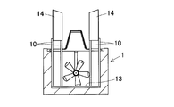
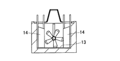
図4A~図4Fは、水力発電装置の集水装置の設置例を段階的に示す図である。水路1の底面に設置した底面板13に、分割した部品を図4A~図4Fの順に設置する。
図4A:水路1の底面に底面板13が設置され、複数の長尺の枠部材10が前述のように設けられる。
図4B:枠部材10に側面板14が上下に案内される。
図4C:側面板14の設置が完了する。
図4D:短尺の枠部材11が設けられた上面板15の設置が開始される。
図4E:上面板15の設置途中である。
図4F:集水装置5の設置が完成する。
図4A~図4Fは、水力発電装置の集水装置の設置例を段階的に示す図である。水路1の底面に設置した底面板13に、分割した部品を図4A~図4Fの順に設置する。
図4A:水路1の底面に底面板13が設置され、複数の長尺の枠部材10が前述のように設けられる。
図4B:枠部材10に側面板14が上下に案内される。
図4C:側面板14の設置が完了する。
図4D:短尺の枠部材11が設けられた上面板15の設置が開始される。
図4E:上面板15の設置途中である。
図4F:集水装置5の設置が完成する。
<集水装置の引き上げ例>
集水装置5は、例えば、図4A~図4Fの逆の順序で部品毎に引き上げられる。但し、複数の部品をまとめて引き上げてもよい。なお、各部品は水路1から全て引き上げてもよいし、一部の部品、例えば、底面板13および複数の枠部材10、または底面板13、複数の枠部材10および側面板14等を水路1に残してもよい。
集水装置5は、例えば、図4A~図4Fの逆の順序で部品毎に引き上げられる。但し、複数の部品をまとめて引き上げてもよい。なお、各部品は水路1から全て引き上げてもよいし、一部の部品、例えば、底面板13および複数の枠部材10、または底面板13、複数の枠部材10および側面板14等を水路1に残してもよい。
<作用効果>
以上説明した集水装置5によれば、複数の分割体、集水装置本体等を順次分割した状態で、簡単に引き上げることができる。つまり、集水装置5の筒体内の空間を満たす水を引き上げなくてもよく、集水装置5を部品単位で分割して引き上げることができるので、引き上げ荷重を小さくすることができる。集水装置5を水路1に設置するとき、複数の分割体、集水装置本体等を個別に組み付けるので、水路1に流れる水に抗して容易に集水装置5を設置することができる。筒体8を前述のような矩形状とすることで、水路1の水を効率良く集水することができる。
以上説明した集水装置5によれば、複数の分割体、集水装置本体等を順次分割した状態で、簡単に引き上げることができる。つまり、集水装置5の筒体内の空間を満たす水を引き上げなくてもよく、集水装置5を部品単位で分割して引き上げることができるので、引き上げ荷重を小さくすることができる。集水装置5を水路1に設置するとき、複数の分割体、集水装置本体等を個別に組み付けるので、水路1に流れる水に抗して容易に集水装置5を設置することができる。筒体8を前述のような矩形状とすることで、水路1の水を効率良く集水することができる。
<他の実施形態について>
以下の説明においては、各実施の形態で先行して説明している事項に対応している部分には同一の参照符号を付し、重複する説明を略する。構成の一部のみを説明している場合、構成の他の部分は、特に記載のない限り先行して説明している形態と同様とする。同一の構成から同一の作用効果を奏する。実施の各形態で具体的に説明している部分の組合せばかりではなく、特に組合せに支障が生じなければ、実施の形態同士を部分的に組合せることも可能である。
以下の説明においては、各実施の形態で先行して説明している事項に対応している部分には同一の参照符号を付し、重複する説明を略する。構成の一部のみを説明している場合、構成の他の部分は、特に記載のない限り先行して説明している形態と同様とする。同一の構成から同一の作用効果を奏する。実施の各形態で具体的に説明している部分の組合せばかりではなく、特に組合せに支障が生じなければ、実施の形態同士を部分的に組合せることも可能である。
<第2の実施形態:スリットを入れた集水装置の例>
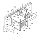
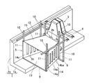
図5および図6に示すように、側面板14を、水路1の水を通すスリットStが形成されたスリット付き部品14aと、スリットStを塞ぐスリット塞ぎ部品14bとを有する構造としてもよい。図5、図6では、スリットStを入れた集水装置5を見やすくするため、水路1の半分を省略している。スリット付き部品14aには、スリットStが格子状に複数形成されている。
図5および図6に示すように、側面板14を、水路1の水を通すスリットStが形成されたスリット付き部品14aと、スリットStを塞ぐスリット塞ぎ部品14bとを有する構造としてもよい。図5、図6では、スリットStを入れた集水装置5を見やすくするため、水路1の半分を省略している。スリット付き部品14aには、スリットStが格子状に複数形成されている。
スリット塞ぎ部品15bは、スリットStを塞ぐ状態(図5)と、スリットStを開口する状態(図6)とに渡って、スリット付き部品14a上で前後に手動によりスライド可能としている。スリット塞ぎ部品14bは、スリット付き部品14a上で前方にスライドした状態で、複数のスリットStとそれぞれ連通する複数の貫通孔14baが形成されている。スリット塞ぎ部品14bは、水路1に浸かった状態において、スリットStを塞ぐ状態(図5)を保持できるうえスリットStを開口する状態(図6)を保持することも可能である。
この構成によると、通常時には、スリット塞ぎ部品14bを、スリット付き部品14a上でスリットStを塞ぐ状態に保持することで水路1の水を効率良く集水することができる。緊急時など溢水のおそれがある場合、スリット塞ぎ部品14bを、スリット付き部品14a上で、スリットStを塞ぐ状態からスリットStを開口する状態にスライドさせる。このようにスリット塞ぎ部品14bを水路1から引き上げることなくスライドさせるだけで、スリットStからの流水を許し、迅速に集水機能を停止することができる。その他、前述の第1の実施形態と同様の作用効果を奏する。
[第3の実施形態]
図7に示すように、側面板14は、流路に沿って複数に分割された側面板分割体14cを有し、各側面板分割体14cを上下に移動可能な枠部材16を備えた構成としてもよい。図8A~図17は、複数の前記側面板分割体14cを備えた集水装置5の設置例を順次示す。図8A,図8Bに示すように、水路1の両側壁面1bの上端に、複数(この例では4つ)の第1の固定用部品17が固定される。第1の固定用部品17として、例えば、杭の打ち込みによる固定またはアンカーボルトによる固定で、第1の固定用部品17が水路1に固定される。図8A中の矢印Fは、水の流れ方向を示している。
図7に示すように、側面板14は、流路に沿って複数に分割された側面板分割体14cを有し、各側面板分割体14cを上下に移動可能な枠部材16を備えた構成としてもよい。図8A~図17は、複数の前記側面板分割体14cを備えた集水装置5の設置例を順次示す。図8A,図8Bに示すように、水路1の両側壁面1bの上端に、複数(この例では4つ)の第1の固定用部品17が固定される。第1の固定用部品17として、例えば、杭の打ち込みによる固定またはアンカーボルトによる固定で、第1の固定用部品17が水路1に固定される。図8A中の矢印Fは、水の流れ方向を示している。
図9~図11に示すように、集水装置の底面板13と、側面板挿入用の複数の枠部材16とを一体にした部品の一部に、図示外の錘を取り付けることで、前記部品が流水により流れにくくなる。また、水路1の両側壁面1bの上端に、二本の第2の固定用部品18,18が架設される。これら第2の固定用部品18,18は、水の流れ方向に所定間隔を隔てて平行に配置され、第1の固定用部品17に連結される。各第2の固定用部品18の上端部には、上面板15(図7)を固定するための上面板固定部品19を差し込む切り欠き18aが形成されている。設置された第2の固定用部品18,18に、複数の枠部材16の一部が固定されることで、集水装置5を水路1の流れ方向に固定することができる。
集水装置5の底面板13と側面板挿入用の枠部材16だけの場合、集水能力はほぼなく、水路によっては、常時、水中に設置することが可能な場合もある。常時、水中に設置することが可能な場合、集水装置5を水路1の流れ方向に固定する第2の固定用部品18と、前記第1の固定用部品17とを、例えば、ボルト(図示せず)により固定することで、水路1に対する集水装置5の位置決めをより確実に行うことができる。
図12~図15に示すように、側面板14を複数に分割された側面板分割体14cとすることで、一枚の側面板分割体14cを引き抜くまたは設置(抜き差し)するのに必要な力を小さくでき、作業効率が上がる。各側面板分割体14cを枠部材16に沿って上下方向に移動させて挿入するとき、前記枠部材16で側面板分割体14cの上下方向以外の自由度を制限することで、水の流れまたは上流から流れてくる異物から不意に負荷を受けなくなり、作業時の安定性が増す。各側面板分割体14cは、側面板挿入用の枠部材16で支えられているので、各側面板分割体14cをボルト等により固定することは不要であり、各側面板分割体14cの抜き差しの作業性を高めることができる。また、各側面板分割体14cは、作業部品20を用いて手作業により抜き差しされる。
図16、図17および図7に示すように、上面板15は、複数(この例は2つ)の上面板固定部品19を用いて複数の側面板分割体14cの上縁部を塞ぐ。図16,17は、上面板15が設置される前の状態を示し、図7は、上面板15が設置された状態を示す。
各上面板固定部品19は、流路方向に沿って延びる固定部品本体部19aと、この固定部品本体部19aから所定間隔を隔てて下方に突出する複数の突出部19bとを有する。固定部品本体部19aは、第2の固定用部品18の切り欠き18aに差し込まれて固定される。固定部品本体部19aの長手方向中間付近から突出する突出部19bは、各先端部が上面板15の上面部を押さえるように設置され、固定部品本体部19aの上流側端から突出する突出部19bが、第2の固定用部品18の上流側表面に当接するように設置される。この集水装置5は、例えば、前述とは逆の順番で部品毎に引き上げられる。
本発明は、以上の実施形態に限定されるものでなく、本発明の要旨を逸脱しない範囲内で、種々の追加、変更または削除が可能である。例えば、上記実施形態の筒体は、流入口から流出口に従って流路幅および流路高さの両方が狭まる形状としているが、流路幅および流路高さのいずれか一方が狭まる形状としてもよい。また筒体の流入口は水路の一部に開口する形状としてもよい。したがって、そのようなものも本発明の範囲内に含まれる。
1…水路
2…水車翼
5…集水装置
6…発電機
8…筒体
13…底面板(集水装置本体)
14…側面板(分割体)
14a…スリット付き部品
14b…スリット塞ぎ部品
14c…側面板分割体
15…上面板(分割体)
16…枠部材
2…水車翼
5…集水装置
6…発電機
8…筒体
13…底面板(集水装置本体)
14…側面板(分割体)
14a…スリット付き部品
14b…スリット塞ぎ部品
14c…側面板分割体
15…上面板(分割体)
16…枠部材
Claims (5)
- 水路に浸かり水力を回転力に変換する水車翼と、この水車翼の回転により発電する発電機とを備えた水力発電装置に用いられ、前記水路における前記水車翼の上流側に設置されて前記水車翼に前記水路の水を集水する水力発電装置用集水装置であって、
流入口が前記水路の一部または全体に開口し流出口が前記水車翼に向かって開口し前記流入口から前記流出口に近づくに従って流路の断面が狭まる筒体を備え、
前記筒体は、一部が残り部分である集水装置本体に対して分離可能な一個または複数の分割体とされた水力発電装置用集水装置。 - 請求項1に記載の水力発電装置用集水装置において、前記筒体は、前記水路の底面に設置される底面板と、この底面板の両側縁部から立ち上がる一対の側面板と、これら側面板の上縁部を塞ぐ上面板と、を有する断面矩形状とされている水力発電装置用集水装置。
- 請求項2に記載の水力発電装置用集水装置において、前記側面板は前記分割体として流路に沿って複数に分割された側面板分割体を有し、前記各側面板分割体を上下に移動可能に案内する枠部材を備えた水力発電装置用集水装置。
- 請求項1ないし請求項3のいずれか1項に記載の水力発電装置用集水装置において、前記複数の分割体の一部として、前記水路の水を通すスリットが形成されたスリット付き部品と、前記スリットを塞ぐスリット塞ぎ部品とを有し、
前記スリット塞ぎ部品は、前記スリットを塞ぐ状態と前記スリットを開口する状態とに渡って、前記スリット付き部品上でスライド可能とした水力発電装置用集水装置。 - 前記水車翼と、前記発電機と、請求項1ないし請求項4のいずれか1項に記載の水力発電装置用集水装置とを備えた水力発電装置。
Applications Claiming Priority (2)
| Application Number | Priority Date | Filing Date | Title |
|---|---|---|---|
| JP2019-145407 | 2019-08-07 | ||
| JP2019145407A JP2021025486A (ja) | 2019-08-07 | 2019-08-07 | 水力発電装置用集水装置および水力発電装置 |
Publications (1)
| Publication Number | Publication Date |
|---|---|
| WO2021024888A1 true WO2021024888A1 (ja) | 2021-02-11 |
Family
ID=74504060
Family Applications (1)
| Application Number | Title | Priority Date | Filing Date |
|---|---|---|---|
| PCT/JP2020/029153 Ceased WO2021024888A1 (ja) | 2019-08-07 | 2020-07-29 | 水力発電装置用集水装置および水力発電装置 |
Country Status (2)
| Country | Link |
|---|---|
| JP (1) | JP2021025486A (ja) |
| WO (1) | WO2021024888A1 (ja) |
Cited By (1)
| Publication number | Priority date | Publication date | Assignee | Title |
|---|---|---|---|---|
| TWI918417B (zh) | 2025-02-18 | 2026-03-11 | 林宜正 | 海浪發電機組載台構造 |
Families Citing this family (1)
| Publication number | Priority date | Publication date | Assignee | Title |
|---|---|---|---|---|
| KR102590421B1 (ko) * | 2022-04-20 | 2023-10-17 | 정의준 | 유량 제어가 가능한 수력 발전 구조물 및 이를 이용한 유량 제어 방법 |
Citations (4)
| Publication number | Priority date | Publication date | Assignee | Title |
|---|---|---|---|---|
| US20070020097A1 (en) * | 2003-10-13 | 2007-01-25 | Ursua Isidro U | Turbine housing and floatation assembly |
| WO2007023879A1 (ja) * | 2005-08-25 | 2007-03-01 | Institute For Energy Application Technologies Co., Ltd. | 発電装置および発電方法 |
| JP2010222875A (ja) * | 2009-03-24 | 2010-10-07 | Keiji Kuboki | 水流加速用の構築体 |
| WO2018105429A1 (ja) * | 2016-12-06 | 2018-06-14 | 株式会社ベルシオン | 加速ダクト |
-
2019
- 2019-08-07 JP JP2019145407A patent/JP2021025486A/ja active Pending
-
2020
- 2020-07-29 WO PCT/JP2020/029153 patent/WO2021024888A1/ja not_active Ceased
Patent Citations (4)
| Publication number | Priority date | Publication date | Assignee | Title |
|---|---|---|---|---|
| US20070020097A1 (en) * | 2003-10-13 | 2007-01-25 | Ursua Isidro U | Turbine housing and floatation assembly |
| WO2007023879A1 (ja) * | 2005-08-25 | 2007-03-01 | Institute For Energy Application Technologies Co., Ltd. | 発電装置および発電方法 |
| JP2010222875A (ja) * | 2009-03-24 | 2010-10-07 | Keiji Kuboki | 水流加速用の構築体 |
| WO2018105429A1 (ja) * | 2016-12-06 | 2018-06-14 | 株式会社ベルシオン | 加速ダクト |
Cited By (1)
| Publication number | Priority date | Publication date | Assignee | Title |
|---|---|---|---|---|
| TWI918417B (zh) | 2025-02-18 | 2026-03-11 | 林宜正 | 海浪發電機組載台構造 |
Also Published As
| Publication number | Publication date |
|---|---|
| JP2021025486A (ja) | 2021-02-22 |
Similar Documents
| Publication | Publication Date | Title |
|---|---|---|
| AU2008239143B2 (en) | Hydraulic power generating apparatus | |
| CN104093970B (zh) | 水力机械 | |
| CN104487702B (zh) | 用于转换流体流动的能量的设备 | |
| BR112016022914B1 (pt) | Aparelho e sistema para gerar eletricidade a partir de fluxo de água | |
| JP2007528467A (ja) | 風洞内の風力タービン | |
| JP2012502215A (ja) | 水力発電設備 | |
| US20250020098A1 (en) | An apparatus for generating electricity from water flow | |
| JP2021025486A (ja) | 水力発電装置用集水装置および水力発電装置 | |
| CN113153627A (zh) | 多层引流的垂直轴风力发电机 | |
| JP5738273B2 (ja) | 発電装置 | |
| JP7274895B2 (ja) | 水力発電装置用集水装置および水力発電装置 | |
| JP7514061B2 (ja) | 水力発電装置 | |
| WO2020184273A1 (ja) | 水力発電装置用集水装置および水力発電装置 | |
| JP2019183825A (ja) | 小型水力発電用水車装置 | |
| US20240159221A1 (en) | Wind powered generator | |
| JP2020051267A (ja) | 水力発電装置 | |
| SE521060C2 (sv) | Vindkraftverk | |
| BR102022023259B1 (pt) | Hidroturbina com difusor de flange curto e aletas estruturais | |
| JP2020148126A (ja) | 小水力発電装置の集水装置 | |
| Wedmark | Pulsation Problems in Hydroelectric Powerplants |
Legal Events
| Date | Code | Title | Description |
|---|---|---|---|
| 121 | Ep: the epo has been informed by wipo that ep was designated in this application |
Ref document number: 20850555 Country of ref document: EP Kind code of ref document: A1 |
|
| NENP | Non-entry into the national phase |
Ref country code: DE |
|
| 122 | Ep: pct application non-entry in european phase |
Ref document number: 20850555 Country of ref document: EP Kind code of ref document: A1 |