WO2021024705A1 - Working machine - Google Patents
Working machine Download PDFInfo
- Publication number
- WO2021024705A1 WO2021024705A1 PCT/JP2020/027167 JP2020027167W WO2021024705A1 WO 2021024705 A1 WO2021024705 A1 WO 2021024705A1 JP 2020027167 W JP2020027167 W JP 2020027167W WO 2021024705 A1 WO2021024705 A1 WO 2021024705A1
- Authority
- WO
- WIPO (PCT)
- Prior art keywords
- battery
- pipe
- brake
- guard
- handle
- Prior art date
Links
Images


Classifications
-
- B—PERFORMING OPERATIONS; TRANSPORTING
- B62—LAND VEHICLES FOR TRAVELLING OTHERWISE THAN ON RAILS
- B62B—HAND-PROPELLED VEHICLES, e.g. HAND CARTS OR PERAMBULATORS; SLEDGES
- B62B5/00—Accessories or details specially adapted for hand carts
- B62B5/0026—Propulsion aids
- B62B5/0033—Electric motors
- B62B5/0053—Arrangements of batteries
-
- B—PERFORMING OPERATIONS; TRANSPORTING
- B60—VEHICLES IN GENERAL
- B60L—PROPULSION OF ELECTRICALLY-PROPELLED VEHICLES; SUPPLYING ELECTRIC POWER FOR AUXILIARY EQUIPMENT OF ELECTRICALLY-PROPELLED VEHICLES; ELECTRODYNAMIC BRAKE SYSTEMS FOR VEHICLES IN GENERAL; MAGNETIC SUSPENSION OR LEVITATION FOR VEHICLES; MONITORING OPERATING VARIABLES OF ELECTRICALLY-PROPELLED VEHICLES; ELECTRIC SAFETY DEVICES FOR ELECTRICALLY-PROPELLED VEHICLES
- B60L50/00—Electric propulsion with power supplied within the vehicle
- B60L50/50—Electric propulsion with power supplied within the vehicle using propulsion power supplied by batteries or fuel cells
- B60L50/60—Electric propulsion with power supplied within the vehicle using propulsion power supplied by batteries or fuel cells using power supplied by batteries
- B60L50/66—Arrangements of batteries
-
- B—PERFORMING OPERATIONS; TRANSPORTING
- B62—LAND VEHICLES FOR TRAVELLING OTHERWISE THAN ON RAILS
- B62B—HAND-PROPELLED VEHICLES, e.g. HAND CARTS OR PERAMBULATORS; SLEDGES
- B62B3/00—Hand carts having more than one axis carrying transport wheels; Steering devices therefor; Equipment therefor
- B62B3/08—Hand carts having more than one axis carrying transport wheels; Steering devices therefor; Equipment therefor involving tiltably-mounted containers
-
- B—PERFORMING OPERATIONS; TRANSPORTING
- B62—LAND VEHICLES FOR TRAVELLING OTHERWISE THAN ON RAILS
- B62B—HAND-PROPELLED VEHICLES, e.g. HAND CARTS OR PERAMBULATORS; SLEDGES
- B62B5/00—Accessories or details specially adapted for hand carts
- B62B5/0026—Propulsion aids
- B62B5/0033—Electric motors
- B62B5/0036—Arrangements of motors
- B62B5/0046—One motor drives two wheels
-
- B—PERFORMING OPERATIONS; TRANSPORTING
- B62—LAND VEHICLES FOR TRAVELLING OTHERWISE THAN ON RAILS
- B62B—HAND-PROPELLED VEHICLES, e.g. HAND CARTS OR PERAMBULATORS; SLEDGES
- B62B5/00—Accessories or details specially adapted for hand carts
- B62B5/04—Braking mechanisms; Locking devices against movement
- B62B5/0404—Braking mechanisms; Locking devices against movement automatic
- B62B5/0414—Braking mechanisms; Locking devices against movement automatic dead man's brakes
-
- H—ELECTRICITY
- H01—ELECTRIC ELEMENTS
- H01M—PROCESSES OR MEANS, e.g. BATTERIES, FOR THE DIRECT CONVERSION OF CHEMICAL ENERGY INTO ELECTRICAL ENERGY
- H01M50/00—Constructional details or processes of manufacture of the non-active parts of electrochemical cells other than fuel cells, e.g. hybrid cells
- H01M50/20—Mountings; Secondary casings or frames; Racks, modules or packs; Suspension devices; Shock absorbers; Transport or carrying devices; Holders
- H01M50/204—Racks, modules or packs for multiple batteries or multiple cells
-
- H—ELECTRICITY
- H01—ELECTRIC ELEMENTS
- H01M—PROCESSES OR MEANS, e.g. BATTERIES, FOR THE DIRECT CONVERSION OF CHEMICAL ENERGY INTO ELECTRICAL ENERGY
- H01M50/00—Constructional details or processes of manufacture of the non-active parts of electrochemical cells other than fuel cells, e.g. hybrid cells
- H01M50/20—Mountings; Secondary casings or frames; Racks, modules or packs; Suspension devices; Shock absorbers; Transport or carrying devices; Holders
- H01M50/233—Mountings; Secondary casings or frames; Racks, modules or packs; Suspension devices; Shock absorbers; Transport or carrying devices; Holders characterised by physical properties of casings or racks, e.g. dimensions
- H01M50/24—Mountings; Secondary casings or frames; Racks, modules or packs; Suspension devices; Shock absorbers; Transport or carrying devices; Holders characterised by physical properties of casings or racks, e.g. dimensions adapted for protecting batteries from their environment, e.g. from corrosion
-
- H—ELECTRICITY
- H01—ELECTRIC ELEMENTS
- H01M—PROCESSES OR MEANS, e.g. BATTERIES, FOR THE DIRECT CONVERSION OF CHEMICAL ENERGY INTO ELECTRICAL ENERGY
- H01M50/00—Constructional details or processes of manufacture of the non-active parts of electrochemical cells other than fuel cells, e.g. hybrid cells
- H01M50/20—Mountings; Secondary casings or frames; Racks, modules or packs; Suspension devices; Shock absorbers; Transport or carrying devices; Holders
- H01M50/233—Mountings; Secondary casings or frames; Racks, modules or packs; Suspension devices; Shock absorbers; Transport or carrying devices; Holders characterised by physical properties of casings or racks, e.g. dimensions
- H01M50/242—Mountings; Secondary casings or frames; Racks, modules or packs; Suspension devices; Shock absorbers; Transport or carrying devices; Holders characterised by physical properties of casings or racks, e.g. dimensions adapted for protecting batteries against vibrations, collision impact or swelling
-
- H—ELECTRICITY
- H01—ELECTRIC ELEMENTS
- H01M—PROCESSES OR MEANS, e.g. BATTERIES, FOR THE DIRECT CONVERSION OF CHEMICAL ENERGY INTO ELECTRICAL ENERGY
- H01M50/00—Constructional details or processes of manufacture of the non-active parts of electrochemical cells other than fuel cells, e.g. hybrid cells
- H01M50/20—Mountings; Secondary casings or frames; Racks, modules or packs; Suspension devices; Shock absorbers; Transport or carrying devices; Holders
- H01M50/244—Secondary casings; Racks; Suspension devices; Carrying devices; Holders characterised by their mounting method
-
- H—ELECTRICITY
- H01—ELECTRIC ELEMENTS
- H01M—PROCESSES OR MEANS, e.g. BATTERIES, FOR THE DIRECT CONVERSION OF CHEMICAL ENERGY INTO ELECTRICAL ENERGY
- H01M50/00—Constructional details or processes of manufacture of the non-active parts of electrochemical cells other than fuel cells, e.g. hybrid cells
- H01M50/20—Mountings; Secondary casings or frames; Racks, modules or packs; Suspension devices; Shock absorbers; Transport or carrying devices; Holders
- H01M50/247—Mountings; Secondary casings or frames; Racks, modules or packs; Suspension devices; Shock absorbers; Transport or carrying devices; Holders specially adapted for portable devices, e.g. mobile phones, computers, hand tools or pacemakers
-
- H—ELECTRICITY
- H01—ELECTRIC ELEMENTS
- H01M—PROCESSES OR MEANS, e.g. BATTERIES, FOR THE DIRECT CONVERSION OF CHEMICAL ENERGY INTO ELECTRICAL ENERGY
- H01M50/00—Constructional details or processes of manufacture of the non-active parts of electrochemical cells other than fuel cells, e.g. hybrid cells
- H01M50/20—Mountings; Secondary casings or frames; Racks, modules or packs; Suspension devices; Shock absorbers; Transport or carrying devices; Holders
- H01M50/249—Mountings; Secondary casings or frames; Racks, modules or packs; Suspension devices; Shock absorbers; Transport or carrying devices; Holders specially adapted for aircraft or vehicles, e.g. cars or trains
-
- H—ELECTRICITY
- H01—ELECTRIC ELEMENTS
- H01M—PROCESSES OR MEANS, e.g. BATTERIES, FOR THE DIRECT CONVERSION OF CHEMICAL ENERGY INTO ELECTRICAL ENERGY
- H01M50/00—Constructional details or processes of manufacture of the non-active parts of electrochemical cells other than fuel cells, e.g. hybrid cells
- H01M50/20—Mountings; Secondary casings or frames; Racks, modules or packs; Suspension devices; Shock absorbers; Transport or carrying devices; Holders
- H01M50/271—Lids or covers for the racks or secondary casings
-
- B—PERFORMING OPERATIONS; TRANSPORTING
- B62—LAND VEHICLES FOR TRAVELLING OTHERWISE THAN ON RAILS
- B62B—HAND-PROPELLED VEHICLES, e.g. HAND CARTS OR PERAMBULATORS; SLEDGES
- B62B5/00—Accessories or details specially adapted for hand carts
- B62B5/04—Braking mechanisms; Locking devices against movement
- B62B2005/0471—Disk brakes
-
- B—PERFORMING OPERATIONS; TRANSPORTING
- B62—LAND VEHICLES FOR TRAVELLING OTHERWISE THAN ON RAILS
- B62B—HAND-PROPELLED VEHICLES, e.g. HAND CARTS OR PERAMBULATORS; SLEDGES
- B62B2203/00—Grasping, holding, supporting the objects
- B62B2203/07—Comprising a moving platform or the like, e.g. for unloading
-
- B—PERFORMING OPERATIONS; TRANSPORTING
- B62—LAND VEHICLES FOR TRAVELLING OTHERWISE THAN ON RAILS
- B62B—HAND-PROPELLED VEHICLES, e.g. HAND CARTS OR PERAMBULATORS; SLEDGES
- B62B2203/00—Grasping, holding, supporting the objects
- B62B2203/10—Grasping, holding, supporting the objects comprising lifting means
-
- B—PERFORMING OPERATIONS; TRANSPORTING
- B62—LAND VEHICLES FOR TRAVELLING OTHERWISE THAN ON RAILS
- B62B—HAND-PROPELLED VEHICLES, e.g. HAND CARTS OR PERAMBULATORS; SLEDGES
- B62B2301/00—Wheel arrangements; Steering; Stability; Wheel suspension
- B62B2301/14—Wheel arrangements; Steering; Stability; Wheel suspension the wheel arrangement pivoting around a horizontal-longitudinal axis
-
- H—ELECTRICITY
- H01—ELECTRIC ELEMENTS
- H01M—PROCESSES OR MEANS, e.g. BATTERIES, FOR THE DIRECT CONVERSION OF CHEMICAL ENERGY INTO ELECTRICAL ENERGY
- H01M2220/00—Batteries for particular applications
- H01M2220/30—Batteries in portable systems, e.g. mobile phone, laptop
-
- Y—GENERAL TAGGING OF NEW TECHNOLOGICAL DEVELOPMENTS; GENERAL TAGGING OF CROSS-SECTIONAL TECHNOLOGIES SPANNING OVER SEVERAL SECTIONS OF THE IPC; TECHNICAL SUBJECTS COVERED BY FORMER USPC CROSS-REFERENCE ART COLLECTIONS [XRACs] AND DIGESTS
- Y02—TECHNOLOGIES OR APPLICATIONS FOR MITIGATION OR ADAPTATION AGAINST CLIMATE CHANGE
- Y02E—REDUCTION OF GREENHOUSE GAS [GHG] EMISSIONS, RELATED TO ENERGY GENERATION, TRANSMISSION OR DISTRIBUTION
- Y02E60/00—Enabling technologies; Technologies with a potential or indirect contribution to GHG emissions mitigation
- Y02E60/10—Energy storage using batteries
Definitions
- the technology disclosed in this specification relates to a working machine.
- a working machine is disclosed in Japanese Patent Application Laid-Open No. 2018-122688.
- the working machine includes a battery box and a battery that is detachably attached to the battery box.
- the battery box has a shape that covers the top cover and the battery attached to the battery box, and includes a battery cover that can rotate around a rotation axis with respect to the top cover.
- the battery box when using the work equipment outdoors in the rain, the battery box may be splashed with water from above.
- the working machine of JP-A-2018-122688 even when water is splashed on the battery box from above, it is possible to prevent the battery from being splashed with water as long as the battery cover is closed.
- the battery box if the battery box is splashed with water from above with the battery cover open, the battery may be splashed with water.
- the present specification provides a technique capable of preventing the battery from being splashed with water even when the battery box is splashed with water from above with the battery cover open.
- the working machine disclosed in the present specification may include a battery box and a battery that can be detachably attached to the battery box.
- the battery box has a shape that covers the top cover and the battery attached to the battery box, and may include a battery cover that can rotate around a rotation axis with respect to the top cover. ..
- the battery cover and the top cover may at least partially overlap each other when the battery box is viewed from above in a plan view with the battery cover open.
- the battery cover and the top cover may at least partially overlap each other when the battery box is viewed in a plan view from above in a closed state in which the battery cover is closed.
- the battery cover and the top cover partially overlap each other when the battery box is viewed from above in a plan view regardless of whether the battery cover is open or closed. Therefore, even if the battery box is splashed with water from above, it is possible to prevent water from entering through the gap between the battery cover and the top cover. It is possible to prevent the battery attached to the battery box from being splashed with water.
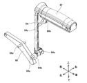
- FIG. 5 is a perspective view of the handle base 16 according to the embodiment as viewed from the front right upper side.
- FIG. 5 is a perspective view of the handle base 16 according to the embodiment as viewed from the rear left upper side.
- FIG. 5 is a perspective view which looked at the right side handle 18 which concerns on embodiment from the rear left upper side.
- FIG. 5 is a perspective view of the left side handle 20 according to the embodiment as viewed from the rear left upper side.
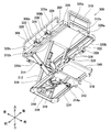
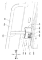
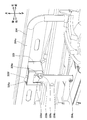
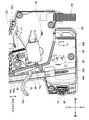
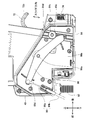
- FIG. 5 is a perspective view of the chassis unit 4 according to the embodiment, in which the right side handle 18 and the left side handle 20 are fixed at the highest positions, as viewed from the front right upper side. It is a side view which looked at the internal structure of the switch box 40 which concerns on embodiment from the right. It is a side view of the switch box 40 according to the embodiment, in a state where the deadman lever 42 is pushed downward and the operating lever 72 is pushed upward, as viewed from the right side. It is a rear view which looked at the chassis unit 4 which concerns on embodiment from the rear.
- FIG. 5 is a perspective view of the positional relationship between the dead man lever 42, the first link member 84, and the pipe 34 according to the embodiment as viewed from the front right upper side.
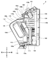
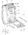
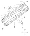
- FIG. 5 is a perspective view of the battery box 8 according to the embodiment as viewed from the rear right upper side.
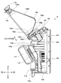
- FIG. 5 is a perspective view of the battery box 8 according to the embodiment as viewed from the front left upper side. It is a vertical cross-sectional view of the battery box 8 which concerns on embodiment.
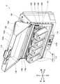
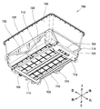
- FIG. 5 is a perspective view of the battery box 8 according to the embodiment, in which the battery cover 106 is opened, as viewed from the rear right upper side.
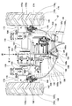
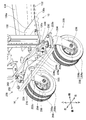
- FIG. 5 is a vertical cross-sectional view of the battery box 8 according to the embodiment in a state where the battery cover 106 is open. It is the top view which looked at the front wheel unit 12 which concerns on Example from above. It is a perspective view which looked at the brake equalizer 148 which concerns on embodiment from the rear right upper side.
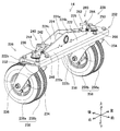
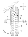
- FIG. 5 is a perspective view of the dead man brake 154 according to the embodiment as viewed from the front right upper side. It is a perspective view which looked at the rear wheel unit 14 which concerns on an Example from the front right upper side. It is a front view which looked at the rear wheel unit 14 which concerns on embodiment from the front.
- FIG. 1 It is a perspective view of the right side caster 226 according to the embodiment, in which the lock pin 242 is held by the second holding portion 244c, as viewed from the front left upper side. It is a top view of the right rear wheel 238 according to the modified example, which is seen from above at an angle of collision with a step S. It is a top view of the right rear wheel 238 according to the modified example as seen from above with respect to the step S. It is a top view of the right rear wheel 238 according to the embodiment seen from above at an angle of collision with a step S. It is a top view of the right rear wheel 238 according to the embodiment as viewed from above with respect to the step S. FIG.
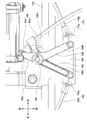
- FIG. 5 is a perspective view of a connection portion between the chassis frame 10 and the rear wheel unit 14 according to the embodiment as viewed from the rear right upper side. It is a vertical cross-sectional view of the connection part of the chassis frame 10 and the rear wheel unit 14 which concerns on embodiment. It is a vertical cross-sectional view of the chassis frame 10 according to the embodiment in a state where the rear wheel unit 14 is rotated.
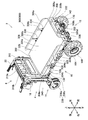
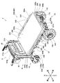
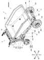
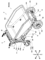
- FIG. 5 is a perspective view of the transport vehicle 2 according to the embodiment, in which the first loading platform unit 300 is attached to the chassis unit 4, as viewed from the front right upper side.
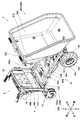
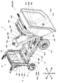
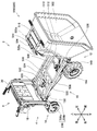
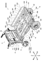
- FIG. 5 is a perspective view of a state in which the first loading platform unit 300 is attached to the chassis unit 4 of the transport vehicle 2 according to the embodiment and the loading platform 302 is raised, as viewed from the front right upper side. It is a perspective view of the 1st loading platform unit 300 according to the embodiment, in which the loading platform 302 is raised, as viewed from the rear left lower side.
- FIG. 5 is a perspective view of the right guard holding portion 328 according to the embodiment, in which the lower end of the support pipe 304b is in contact with the support plate 328c, as viewed from the front right upper side.
- FIG. 5 is a perspective view of the right side guard holding portion 328 according to the embodiment, in which the lower surface of the guard pipe 304a is in contact with the edge of the right guard holding portion 328, as viewed from the front right upper side.
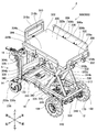
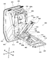
- FIG. 5 is a perspective view of the transport vehicle 2 according to the embodiment, in which the second loading platform unit 400 is attached to the chassis unit 4, as viewed from the front right upper side.
- the second loading platform unit 400 is attached to the chassis unit 4 of the transport vehicle 2 according to the embodiment, the movable support platform 408 is tilted with respect to the fixed support platform 412, and the bucket support platform 404 is mounted on the movable support platform 408. It is a perspective view seen from the front right upper side in the state inclined with respect to.
- the movable support base 408 of the second loading platform unit 400 according to the embodiment is tilted with respect to the fixed support base 412, and the bucket support base 404 is tilted with respect to the movable support base 408. It is a perspective view seen from. It is a perspective view of the transport vehicle 2 according to the embodiment, in which the third loading platform unit 500 is attached to the chassis unit 4, as viewed from the front right upper side. A perspective view of a state in which the third loading platform unit 500 is attached to the chassis unit 4 of the transport vehicle 2 according to the embodiment and the movable support platform 504 is tilted with respect to the fixed support platform 508, as viewed from the front right upper side. It is a figure. FIG.
- FIG. 5 is a perspective view of the third loading platform unit 500 according to the embodiment, in which the movable support platform 504 is tilted with respect to the fixed support platform 508, as viewed from the rear left upper side. It is a perspective view of the transport vehicle 2 according to the embodiment, in which the fourth loading platform unit 600 is attached to the chassis unit 4, as viewed from the front right upper side. It is a perspective view which looked at the 4th loading platform unit 600 which concerns on embodiment from the rear right lower side. It is a perspective view of the transport vehicle 2 according to the embodiment, in which the fifth loading platform unit 700 is attached to the chassis unit 4, as viewed from the front right upper side. FIG. 5 is a perspective view of the fifth loading platform unit 700 according to the embodiment as viewed from the rear left lower side.
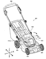
- FIG. 5 is a perspective view of the positional relationship between the deadman lever 42, the first link member 84, and the second link member 86 according to the modified example, as viewed from the rear left upper side. It is a side view which looked at the internal structure of the switch box 40 which concerns on a modification from the right side. It is a side view which looked at the internal structure of the switch box 40 which concerns on a modification from the left. It is a perspective view which looked at the lawn mower 902 which concerns on the modification from the front right upper side.
- the work equipment may include a battery box and a battery that is detachably attached to the battery box.
- the battery box has a shape that covers the top cover and the battery attached to the battery box, and may include a battery cover that can rotate around a rotation axis with respect to the top cover. ..
- the battery cover and the top cover may at least partially overlap each other when the battery box is viewed from above in a plan view with the battery cover open.
- the battery cover and the top cover may at least partially overlap each other when the battery box is viewed in a plan view from above in a closed state in which the battery cover is closed.
- the battery cover and the top cover partially overlap each other when the battery box is viewed from above in a plan view regardless of whether the battery cover is open or closed. Therefore, even if the battery box is splashed with water from above, it is possible to prevent water from entering through the gap between the battery cover and the top cover. It is possible to prevent the battery attached to the battery box from being splashed with water.
- the battery attached to the battery box and the battery cover may overlap when the battery box is viewed from above in the open state. ..
- the battery cover covers the upper part of the battery, so that the battery is splashed with water even when the battery box is splashed with water from above. Can be prevented.
- a recess extending along the rotation axis may be formed in the upper part of the battery cover.
- the water adhering to the upper part of the battery cover can be guided by the concave portion so as to flow along the outer surface of the battery cover, so that it is possible to prevent the battery from being splashed with water.
- the battery box may further include a water pan located inside the battery box and above the battery.
- the top surface of the top cover and the top surface of the battery cover may be inclined with respect to a horizontal plane.
- the battery can also be used in other electrical devices.
- the battery can be shared between the work machine and other electric devices, and the convenience of the user can be improved.
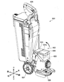
- the transport vehicle 2 of this embodiment is a hand-push type transport vehicle which is a kind of working machine.
- the transport vehicle 2 includes the chassis unit 4 shown in FIG. 1, the first loading platform unit 300 shown in FIG. 39, the second loading platform unit 400 shown in FIG. 45, the third loading platform unit 500 shown in FIG. 49, and the fourth carrier unit shown in FIG. 52. It is configured by detachably attaching one of the loading platform unit 600 and the fifth loading platform unit 700 shown in FIG. 54.
- the carrier 2 is attached to the chassis unit 4 by one of a first carrier unit 300, a second carrier unit 400, a third carrier unit 500, a fourth carrier unit 600, and a fifth carrier unit 700. One may be attached so as not to be detachable.
- first loading platform unit 300 the second loading platform unit 400, the third loading platform unit 500, the fourth loading platform unit 600, and the fifth loading platform unit 700
- chassis unit 4 those attached to the chassis unit 4 are referred to. It is also simply referred to as a loading platform unit 800.
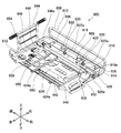
- chassis unit 4 As shown in FIG. 1, the chassis unit 4 includes a steering wheel unit 6, a battery box 8, a chassis frame 10, a front wheel unit 12, and a rear wheel unit 14.
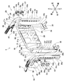
- the handle unit 6 includes a handle base 16, a right side handle 18, and a left side handle 20.
- the handle base 16 includes a base pipe 21, a right channel 22, a left channel 24, a square pipe 26, a base plate 28, a right mounting bracket 30, and a left mounting bracket 32.
- the base pipe 21, the right channel 22, the left channel 24, the square pipe 26, the base plate 28, the right mounting bracket 30, and the left mounting bracket 32 are all made of steel.
- the cross-sectional shape of the base pipe 21 is substantially circular.
- the base pipe 21 includes a central portion 21a extending in the left-right direction, a right side support portion 21b bent downward from the right end of the central portion 21a, and a left side support portion 21c bent downward from the left end of the central portion 21a.
- the right channel 22 includes a web 22a along the front-rear and up-down directions, a front flange 22b bent left from the front end of the web 22a, and a rear flange 22c bent left from the rear end of the web 22a. There is.
- the right support portion 21b of the base pipe 21 is welded to the right channel 22 on the upper left side of the right channel 22.
- the left channel 24 includes a web 24a along the front-rear and up-down directions, a front flange 24b bent to the right from the front end of the web 24a, and a rear flange 24c bent to the right from the rear end of the web 24a.
- the left support portion 21c of the base pipe 21 is welded to the left channel 24 on the upper right side of the left channel 24.
- the square pipe 26 extends in the left-right direction.
- the right end of the square pipe 26 is welded to the right channel 22 on the left side near the central portion in the vertical direction of the right channel 22.
- the left end of the square pipe 26 is welded to the left channel 24 on the right side near the central portion in the vertical direction of the left channel 24.
- the base plate 28 includes a wall portion 28a along the vertical and horizontal directions, and a floor portion 28b bent rearward from the lower end of the wall portion 28a.
- the upper end of the wall portion 28a is welded to the lower surface of the central portion 21a of the base pipe 21.
- the lower surface of the floor portion 28b is welded to the upper surface of the square pipe 26.
- the right side mounting bracket 30 is welded to the lower end of the right side channel 22.
- the left side mounting bracket 32 is welded to the lower end of the left side channel 24. As shown in FIG. 1, in the handle base 16, the right side mounting bracket 30 is screwed to the frame plate 130 of the chassis frame 10, and the left side mounting bracket 32 is screwed to the frame plate 130 of the chassis frame 10. It is fixed to the frame 10.
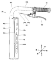
- the right handle 18 includes a pipe 34, a channel 36, a grip 38, a switch box 40, and a deadman lever 42.
- Both the pipe 34 and the channel 36 are made of steel.
- the pipe 34 includes a support portion 34a extending in the vertical direction and a handle portion 34b bent rearward from the upper end of the support portion 34a.
- the channel 36 includes a web 36a along the front-rear and vertical directions, a front flange 36b bent to the right from the front end of the web 36a, and a rear flange 36c bent to the right from the rear end of the web 36a. ..
- the pipe 34 is welded to the channel 36 on the right side of the channel 36.
- the grip 38, the switch box 40, and the deadman lever 42 are attached to the handle portion 34b of the pipe 34.
- the left handle 20 includes a pipe 44, a channel 46, a grip 48, and a brake lever 49. Both the pipe 44 and the channel 46 are made of steel.
- the pipe 44 includes a support portion 44a extending in the vertical direction and a handle portion 44b bent rearward from the upper end of the support portion 44a.
- the channel 46 includes a web 46a along the front-rear and up-down directions, a front flange 46b bent left from the front end of the web 46a, and a rear flange 46c bent left from the rear end of the web 46a. ..
- the pipe 44 is welded to the channel 46 on the left side of the channel 46.
- the grip 48 and the brake lever 49 are attached to the handle portion 44b of the pipe 44.
- the right handle 18 is fixed to the handle base 16 via the grip bolts 50 and 52.
- the left handle 20 is fixed to the handle base 16 via grip bolts 54 and 56.
- the grip bolts 50, 52, 54, and 56 are provided with head portions 50a, 52a, 54a, 56a and shaft portions 50b, 52b, 54b, 56b, respectively.
- through holes 22d and 22e are formed side by side in the vertical direction on the web 22a of the right channel 22 of the handle base 16.
- nuts 58 and 60 are welded to the left surface of the web 22a of the right channel 22 at positions corresponding to the through holes 22d and 22e.
- through holes 24d and 24e are formed side by side in the vertical direction on the web 24a of the left channel 24 of the handle base 16.
- nuts 62 and 64 are welded to the right side of the web 24a of the left channel 24 at positions corresponding to the through holes 24d and 24e.
- the web 36a of the channel 36 of the right handle 18 is formed with an elongated hole 36d extending in the vertical direction.
- the web 46a of the channel 46 of the left handle 20 is formed with an elongated hole 46d extending in the vertical direction.
- the shaft portion 50b of the grip bolt 50 is passed through the elongated hole 36d of the right handle 18 and the through hole 22d of the handle base 16.
- the shaft portion 52b of the grip bolt 52 is screwed into the nut 58, and the elongated hole 36d of the right handle 18 and the through hole 22e of the handle base 16 are passed through and screwed into the nut 60.
- the left side of the web 36a of the channel 36 of the right handle 18 is in contact with the right side of the web 22a of the right channel 22 of the handle base 16, and the heads 50a and 52a of the grip bolts 50 and 52 and the nut 58, The 60 sandwiches the channel 36 of the right handle 18 and the right channel 22 of the handle base 16.
- the right side handle 18 can be fixed to the handle base 16.
- the grip bolts 50 and 52 and the nuts 58 and 60 are collectively referred to as the right side holding mechanism 51.
- the grip bolt 52 and the nut 60 are also referred to as a right side rotation regulation mechanism 53.
- the right side rotation regulation mechanism 53 regulates that the right side handle 18 rotates with respect to the handle base 16 with the grip bolt 50 as a rotation axis.
- the shaft portion 54b of the grip bolt 54 is passed through the elongated hole 46d of the left handle 20 and the through hole 24d of the handle base 16 to the nut 62.
- the shaft portion 56b of the grip bolt 56 is screwed into the nut 64 through the elongated hole 46d of the left handle 20 and the through hole 24e of the handle base 16.
- the right side of the web 46a of the channel 46 of the left handle 20 is in contact with the left side of the web 24a of the left channel 24 of the handle base 16, and the heads 54a, 56a of the grip bolts 54, 56 and the nut 62, 64 sandwiches the channel 46 of the left handle 20 and the left channel 24 of the handle base 16.
- the left side handle 20 can be fixed to the handle base 16.
- the grip bolts 54 and 56 and the nuts 62 and 64 are collectively referred to as the left side holding mechanism 55.
- the grip bolt 56 and the nut 64 are also referred to as a left rotation regulation mechanism 57.
- the left side rotation regulation mechanism 57 regulates that the left side handle 20 rotates with respect to the handle base 16 with the grip bolt 54 as a rotation axis.
- the right handle 18 can move up and down with respect to the handle base 16 with the grip bolts 50 and 52 loosened.
- the right handle 18 can be fixed to the handle base 16 at the adjusted position by tightening the grip bolts 50 and 52 in a state where the vertical position with respect to the handle base 16 is adjusted to a desired position.
- the left handle 20 can move in the vertical direction with respect to the handle base 16 with the grip bolts 54 and 56 loosened.
- the left handle 20 can be fixed to the handle base 16 at the adjusted position by tightening the grip bolts 54 and 56 in a state where the vertical position with respect to the handle base 16 is adjusted to a desired position.
- the right side handle 18 and the left side handle 20 are integrated and the vertical position with respect to the handle base 16 is adjusted integrally, the weight of the integrated right side handle 18 and the left side handle 20 is large. Therefore, a large amount of labor is required to adjust the vertical position with respect to the handle base 16.
- the right side handle 18 and the left side handle 20 are separate bodies, and the positions in the vertical direction with respect to the handle base 16 can be individually adjusted. In this case, since the weights of the individual right-hand handle 18 and the left-hand handle 20 are not so large, the labor required for adjusting the vertical position with respect to the handle base 16 can be reduced.
- an elastic engaging piece 22f projecting to the right is formed on the web 22a of the right channel 22 of the handle base 16.
- an elastic engaging piece 24f projecting to the left is formed on the web 24a of the left channel 24 of the handle base 16.
- the elastic engaging piece 22f of the right channel 22 and the elastic engaging piece 24f of the left channel 24 are substantially the same in the vertical direction.
- a plurality of engaging holes 36e are formed in the web 36a of the channel 36 of the right handle 18 corresponding to the elastic engaging piece 22f of the right channel 22.
- the plurality of engaging holes 36e are arranged side by side at predetermined intervals in the vertical direction.
- a plurality of engaging holes 46e are formed in the web 46a of the channel 46 of the left handle 20 corresponding to the elastic engaging piece 24f of the left channel 24.
- the plurality of engaging holes 46e are arranged side by side at predetermined intervals in the vertical direction.
- Each of the plurality of engaging holes 36e of the right side handle 18 and each of the plurality of engaging holes 46e of the left side handle 20 are substantially the same in the vertical direction.
- the right handle 18 can be fixed to the handle base 16 in a state where the elastic engaging piece 22f is inserted into one of the plurality of engaging holes 36e.
- the left handle 20 can be fixed to the handle base 16 in a state where the elastic engaging piece 24f is inserted into one of the plurality of engaging holes 46e.
- the vertical mounting position of the right handle 18 with respect to the handle base 16 and the left side with respect to the handle base 16 The mounting positions of the handles 20 in the vertical direction can be substantially the same.
- the right handle 18 is fixed to the handle base 16 in a state where the elastic engaging piece 22f is inserted into the uppermost one of the plurality of engaging holes 36e, and among the plurality of engaging holes 46e.
- both the right handle 18 and the left handle 20 are fixed as shown in FIG.
- the right handle 18 is fixed to the handle base 16 with the elastic engaging piece 22f inserted into the lowest of the plurality of engaging holes 36e, and among the plurality of engaging holes 46e.
- the left handle 20 is fixed to the handle base 16 with the elastic engaging piece 24f inserted into the bottom one, both the right handle 18 and the left handle 20 are fixed as shown in FIG. , Can be fixed at the highest position with respect to the handle base 16.
- the elastic engaging piece 22f and the plurality of engaging holes 36e are collectively referred to as the right side positioning mechanism 23
- the elastic engaging piece 24f and the plurality of engaging holes 46e are collectively referred to as the left side positioning mechanism 25. ..
- the right handle 18 may be fixed to the handle base 16 by tightening the grip bolts 50 and 52 in a state where the elastic engaging piece 22f is not inserted into any of the plurality of engaging holes 36e. it can. In this case, the elastic engagement piece 22f is pressed by the web 36a of the channel 36 and is maintained in a state of being elastically deformed to the left side.
- the left handle 20 is fixed to the handle base 16 by tightening the grip bolts 54 and 56 in a state where the elastic engaging piece 24f is not inserted into any of the plurality of engaging holes 46e. You can also. In this case, the elastic engagement piece 24f is pressed by the web 46a of the channel 46 and is maintained in a state of being elastically deformed to the right.
- the handle portion 34b of the right handle 18 may be bent to the right or left from the upper end of the support portion 34a, and the handle portion 44b of the left handle 20 is the upper end of the support portion 44a. It may be bent to the right or left.
- the right side handle 18 and the left side handle 20 may be integrally formed, for example, a U-shaped handle.
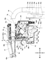
- the switch box 40 includes a casing 66, an operation panel 68, a warning button 70, an operation lever 72, and a taillight 74.
- the casing 66 is a resin member.
- the operation panel 68 is provided on the upper surface of the casing 66.
- the operation panel 68 includes a main power button 68a, a main power indicator 68b, a forward / backward switching button 68c, a forward indicator 68d, a backward indicator 68e, a speed switching button 68f, and a speed indicator 68g.
- the main power button 68a is a button for the user to switch the main power of the carrier 2 on / off.
- the main power indicator lamp 68b is turned on when the main power of the carrier 2 is on, and is turned off when the main power of the carrier 2 is off.
- the forward / backward switching button 68c is a button for the user to switch the forward mode / backward mode of the carrier 2.
- the carrier 2 drives a motor 150 (see FIG. 1) described later to rotate the right front wheel 140 and the left front wheel 142 (see FIG. 1) described later in the forward direction, and in the reverse mode, the transport vehicle 2 rotates in the forward direction.
- the carrier 2 drives a motor 150 to rotate the right front wheel 140 and the left front wheel 142 in opposite directions.
- the forward indicator light 68d is turned on when the transport vehicle 2 is operated in the forward mode, and is turned off when the carrier 2 is operated in the backward mode.
- the reverse indicator light 68e is turned on when the transport vehicle 2 operates in the backward mode and turns off when the carrier 2 operates in the forward mode.
- the speed switching button 68f is a button for the user to switch the traveling speed of the carrier 2. In the transport vehicle 2 of the present embodiment, the traveling speed can be switched in multiple stages (for example, in three stages).
- the transport vehicle 2 controls the rotation speed of the motor 150 when driving the motor 150 according to the traveling speed set by the speed switching button 68f.
- the speed indicator 68g changes the number of windows to be lit according to the traveling speed of the transport vehicle 2 set by the speed switching button 68f.
- the operation board 76 is housed inside the casing 66 and below the operation panel 68.
- the operation board 76 includes a main power button 68a, a forward / backward switching button 68c, a switch (not shown) for detecting the user's operation on the speed switching button 68f, a main power indicator 68b, a forward / backward indicator 68d, and a backward display. It is equipped with an LED (not shown) for turning on / off the light 68e and the speed indicator 68g.
- the warning button 70 is provided on the side surface of the casing 66 and to the left of the operation panel 68.
- the warning button 70 is a button for the user to perform a ringing operation of the buzzer 124 (see FIG. 13) described later.
- the carrier 2 sounds the buzzer 124 to generate a warning sound.
- the transport vehicle 2 is provided with a speaker (not shown) other than the buzzer 124, the transport vehicle 2 outputs predetermined music or voice from the speaker in response to the operation of the warning button 70 by the user. It may be configured to be used.
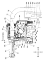
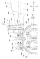
- the operation lever 72 is a resin member. As shown in FIG. 8, the operation lever 72 includes a support portion 72a, an operation piece 72b, and a detection piece 72c.
- the support portion 72a, the operation piece 72b, and the detection piece 72c are integrally formed.
- the support portion 72a and the detection piece 72c are housed inside the casing 66.
- the operation piece 72b projects from the inside to the outside of the casing 66 through the opening 66a formed on the rear surface of the casing 66.
- the support portion 72a is rotatably supported around the rotation shaft 72d extending in the left-right direction with respect to the casing 66.
- a drive switch 78 is housed in the vicinity of the detection piece 72c.
- the operation piece 72b When the operation piece 72b is pushed upward by the user, the operation piece 72b, the support portion 72a, and the detection piece 72c are integrally rotated around the rotation shaft 72d, and as shown in FIG. 9, the detection piece 72b is detected.
- the drive switch 78 is pressed by the piece 72c.
- a compression spring (not shown) that applies torque in the direction in which the operation piece 72b moves downward to the operation lever 72 is housed.
- the operation piece 72b, the support portion 72a, and the detection piece 72c are integrally rotated around the rotation shaft 72d by the urging force of the compression spring, as shown in FIG. As described above, the detection piece 72c separates from the drive switch 78.
- the opening 66a of the casing 66 is covered with the bellows cover 80.
- the bellows cover 80 prevents foreign matter from entering the inside of the casing 66 from the outside of the casing 66 through the opening 66a.
- the operation panel 68 is arranged on the upper surface of the casing 66.
- the warning button 70 is arranged on the side surface of the casing 66.
- the operating lever 72 is arranged at the rear portion of the casing 66.
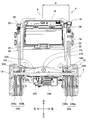
- the taillight 74 is the rear surface of the casing 66 and is provided below the operation lever 72.
- the taillight 74 is turned on when the right headlight 156 and the left headlight 158, which will be described later, are on, and is turned off when the taillight 74 is off.
- the taillight 74 illuminates the rear of the transport vehicle 2 and functions as a high visibility unit.
- the taillight substrate 82 is housed inside the casing 66 and in front of the taillight 74.
- the taillight substrate 82 includes LEDs (not shown) for turning on / off the taillight 74.
- the taillight 74 may be turned on / off by, for example, a surface-emitting LED.
- the taillight 74 is arranged in front of the grip 38, for example, when the transport vehicle 2 is moving backward, even if it collides with an obstacle behind, the grip 38 is the obstacle first. Since it collides with an object, it is possible to prevent the taillight 74 from colliding with an obstacle and being damaged.
- the brightness of the taillight 74 is such that the lighting of the taillight 74 can be visually recognized from a distance of 100 m behind at night. Further, it is desirable that the color emitted by the taillight 74 is a color including red, specifically, orange, red, or the like.
- the standard for the tail light of a bicycle specified in JIS C9502 is satisfied. Anything is fine.
- the transport vehicle 2 may be configured to light the tail light 74 in conjunction with the activation of the transport vehicle 2.
- the transport vehicle 2 may turn on the tail light 74 or blink it.
- the transport vehicle 2 may have a configuration in which the tail light 74 is normally turned on, and the tail light 74 blinks when the deceleration state of the transport vehicle 2 is detected by an acceleration sensor (not shown) or the like.
- the transport vehicle 2 may have a configuration in which the taillight 74 is normally turned off and the taillight 74 is turned on when the optical sensor (not shown) or the like detects that the surroundings have become dark.
- the drive of the motor 150 may be detected by a vibration sensor (not shown) or the like, and the tail light 74 may be turned on when the surroundings become dark and the motor 150 is driven.
- the transport vehicle 2 supplies power to the taillight 74 with the power supply to the motor 150, the loading platform unit 800, and the like stopped. It may be a continuous configuration.
- the transport vehicle 2 may be provided with a reflective material (not shown) on the rear surface of the casing 66 instead of the tail light 74.
- the reflective material receives and reflects light to illuminate the rear of the transport vehicle 2 and functions as a high visibility unit.
- the reflector may include a retroreflective material. It is desirable that the reflective material has a performance that allows the reflected light to be visually recognized when the light is irradiated by a car headlight or the like from a distance of 100 m behind at night. Further, it is desirable that the color of the light reflected by the reflective material is a color including red, specifically, orange, red, or the like.
- a taillight 74 combined with a reflective material may be used to further improve visibility from the rear. In this case, the taillight 74 and the reflective material may be integrated.
- the distance D from the center of the chassis unit 4 in the left-right direction to the center of the taillight 74 in the left-right direction is 150 mm or more, preferably 200 mm or more. For example, it is about 250 mm.
- the distance D is 150 mm or more
- the distance between the right handle 18 and the left handle 20 is 300 mm or more, which is wider than the standard adult waist width.
- the distance between the right handle 18 and the left handle 20 is 400 mm or more, which is wider than the standard adult shoulder width.
- the distance D can be selected based on the above-mentioned standard waist width and shoulder width in consideration of the posture of the operator based on the shapes of the right side handle 18 and the left side handle 20. With such a configuration, even when the user holds the right side handle 18 and the left side handle 20 and stands behind the carrier 2, the taillight 74 is not obstructed by the user's body and is behind the user. The taillight 74 can be visually recognized from.
- the center of the chassis unit 4 in the left-right direction is a position corresponding to the center of the user's body in the left-right direction when the user holds the right handle 18 and the left handle 20 and stands behind the carrier 2.
- the taillight 74 is a position other than the switch box 40 as long as the user is standing behind the carrier 2 while holding the right handle 18 and the left handle 20 and can be seen from behind the user. It may be provided at another position of the chassis unit 4.
- the taillight 74 may be provided on the right channel 22 or the left channel 24 of the handle base 16.
- the taillight 74 may be provided on the channel 36 of the right handle 18 or on the rear end surface of the grip 38.
- the taillight 74 may be provided on the channel 46 of the left handle 20 or on the rear end surface of the grip 48.
- the taillight 74 may be provided in the rear wheel frame 225 of the rear wheel unit 14, which will be described later, in the vicinity of the right rear wheel 238 or in the vicinity of the left rear wheel 258. Even when the taillight 74 is provided at these locations, it is desirable that the lighting can be visually recognized from a distance of 100 m behind at night.
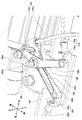
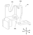
- the casing 66 further houses the first link member 84, the second link member 86, and the deadman switch 88.
- the first link member 84 is held in the casing 66 so as to be slidable in a predetermined sliding direction (see the arrows in FIGS. 8 and 9).
- the first link member 84 includes a support beam 84a that extends substantially linearly from the upper end to the lower end, and an auxiliary beam that extends to the right from the intermediate portion of the support beam 84a and then bends upward. It includes 84b and a pin 84c extending to the right from the lower end of the support beam 84a. As shown in FIGS.
- the support beam 84a extends from the upper part to the lower part inside the casing 66 on the left side of the operating lever 72.
- the auxiliary beam 84b is formed in a shape that does not interfere with the grip 38 located above and the operating lever 72 located below within the movable range of the first link member 84.
- the second link member 86 is rotatably held in the casing 66 around a rotation shaft 86a extending in the left-right direction.
- An elongated hole 86b is formed at the rear end of the second link member 86.
- the pin 84c of the first link member 84 is inserted into the elongated hole 86b of the second link member 86.
- the deadman switch 88 is arranged so as to face the protrusion 86c formed on the second link member 86.
- the protrusion 86c presses the deadman switch 88 so that the rear end of the second link member 86 moves downward.
- the protrusion 86c separates from the deadman switch 88.
- the second link member 86 is urged by a torsion spring (not shown) in a rotation direction in which the rear end moves upward.
- a cable holder 86d is provided at the front end of the second link member 86.
- a deadman cable 90 is inserted in the lower front portion of the casing 66.
- the deadman cable 90 includes an inner cable 90a and an outer cable 90b that covers the periphery of the inner cable 90a.
- the outer cable 90b is held in the casing 66.
- the inner cable 90a is held in the cable holder 86d.
- the deadman lever 42 is formed in a shape along the upper surface of the grip 38.
- the deadman lever 42 is a resin member.
- the rear end of the deadman lever 42 is rotatably held by the rear end of the grip 38 via a rotation shaft 42a extending in the left-right direction.
- the front end of the deadman lever 42 is slidably held by the upper end of the first link member 84.
- the deadman lever 42 When the user grips the grip 38, the deadman lever 42 is pushed downward by the user's palm. In this case, the first link member 84 moves downward along the sliding direction, and the second link member 86 rotates in the rotational direction in which the rear end faces downward. As a result, as shown in FIG. 9, the inner cable 90a of the deadman cable 90 is pulled out relative to the outer cable 90b. Further, the protrusion 86c of the second link member 86 separates from the deadman switch 88. When the user releases the grip 38 from this state, the rear end of the second link member 86 rotates in the upward rotation direction due to the urging force of the torsion spring, and the first link member 84 rotates in the sliding direction. Move upwards along.
- the inner cable 90a of the deadman cable 90 is pushed relative to the outer cable 90b. Further, the protrusion 86c of the second link member 86 presses the deadman switch 88. Further, the front end of the deadman lever 42 is pushed upward.
- the first link member 84 and the second link member 86 may be configured as shown in FIG. 62.
- the pin 84c of the first link member 84 extends to the left from the lower end of the support beam 84a.
- the first link member 84 includes a roller 84d rotatably held by the pin 84c, and a block 84e protruding to the right from the lower end of the support beam 84a.
- the elongated hole 86b and the protrusion 86c are not formed on the second link member 86.
- the roller 84d of the first link member 84 is in contact with the upper surface of the second link member 86 in the vicinity of the rear end of the second link member 86.
- the space inside the casing 66 is partitioned to the left and right by the inner wall 66b.
- An elongated hole 66c is formed in the inner wall 66b.
- the longitudinal direction of the elongated hole 66c is along the sliding direction of the first link member 84.
- the support beam 84a and the block 84e of the first link member 84 and the deadman switch 88 are arranged in the space on the right side of the inner wall 66b.
- the pin 84c of the first link member 84 penetrates the elongated hole 66c.
- the roller 84d of the first link member 84, the second link member 86, and the deadman cable 90 are arranged in the space on the left side of the inner wall 66b.
- the second link member 86 rotates in the rotational direction in which the front end is directed downward and the rear end is directed upward due to the urging force of a torsion spring (not shown).
- a torsion spring (not shown)
- the inner cable 90a of the deadman cable 90 is pushed relative to the outer cable 90b.
- the roller 84d is pushed upward by the upper surface of the second link member 86
- the first link member 84 moves upward along the sliding direction, and the block 84e of the first link member 84 is moved from the deadman switch 88. Separate. Further, the front end of the deadman lever 42 is pushed upward.
- a signal cable 92 is inserted in the lower part of the front end of the casing 66.
- the wiring extending from the operation board 76, the warning button 70, the drive switch 78, the taillight board 82, and the deadman switch 88 inside the casing 66 is drawn out to the outside of the casing 66 via the signal cable 92.
- the brake cable 94 is connected to the brake lever 49.
- the brake cable 94 includes an inner cable 94a and an outer cable 94b that covers the periphery of the inner cable 94a.
- the brake lever 49 is pushed downward by the urging force of a torsion spring (not shown).
- a torsion spring (not shown).
- the inner cable 94a of the brake cable 94 is pulled out relative to the outer cable 94b.
- the urging force of the torsion spring pushes down the brake lever 49, and the inner cable 94a of the brake cable 94 is pushed relative to the outer cable 94b.
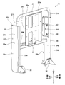
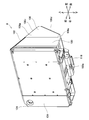
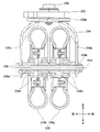
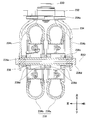
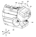
- the battery box 8 includes a casing 100, a top cover 102, a front cover 104, and a battery cover 106.
- the casing 100, the top cover 102, the front cover 104, and the battery cover 106 are resin members.
- the casing 100 has a box shape.
- a top cover 102 is attached to the upper surface of the casing 100.
- the top cover 102 has a substantially flat plate shape, and is inclined from the upper side to the lower side from the front to the rear.
- a front cover 104 is attached to the front surface of the casing 100.
- the front cover 104 has a substantially flat plate shape and is substantially orthogonal to the front-rear direction.
- the battery box 8 is mounted on the floor 28b (see FIG. 2) of the base plate 28 of the handle unit 6, and the front cover 104 is screwed to the wall 28a (see FIG. 2) of the base plate 28 to handle the battery box 8. It is fixed to the unit 6.
- the control board 108 is housed inside the casing 100. Further, a plurality of battery mounting portions 110 are provided on the rear surface of the casing 100. A plurality of battery packs 112 are detachably attached to the plurality of battery mounting portions 110. Each of the plurality of battery packs 112 has a built-in secondary battery cell such as a lithium ion battery cell (not shown), and can be charged by a charger (not shown). Each of the plurality of battery packs 112 has a rated voltage of 18 V and a rated capacity of 6.0 Ah, respectively. The plurality of battery packs 112 can also be used in electric devices other than the transport vehicle 2, for example, electric tools such as electric screwdrivers, and electric work machines such as electric lawnmowers.
- a plurality of (for example, four) battery packs 112 are used in the first group (for example, the two on the left side) of the battery pack 112a and the second group. It is classified into battery packs 112b (for example, the two on the right).
- the transport vehicle 2 of the present embodiment uses a state in which the battery packs 112a of the first group are connected in series as a power source for the transport vehicle 2, and a transport vehicle in which the battery packs 112b of the second group are connected in series. It is possible to switch between the states used as the power source of 2.
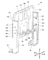
- the battery cover 106 is attached to the casing 100 via a hinge 106a provided at the upper end of the battery cover 106.
- the battery cover 106 is rotatable around a rotation shaft 106b extending in the left-right direction with respect to the casing 100.
- the battery cover 106 is formed continuously from the upper inclined surface 106c which is inclined from the front to the rear from the upper side to the lower side and the upper inclined surface 106c, and is formed upward.
- a lower inclined surface 106d that is inclined from the rear to the front as it goes downward, and a bottom surface 106e that is continuously formed from the lower inclined surface 106d and is substantially orthogonal to the vertical direction, and an upper inclined surface.
- the battery cover 106 covers the periphery of the plurality of battery packs 112 attached to the plurality of battery mounting portions 110 when the battery cover 106 is closed with respect to the casing 100.
- the upper surface of the top cover 102 and the upper surface of the battery cover 106 are inclined with respect to the horizontal plane, so that even if water adheres to the upper surface of the top cover 102 or the battery cover 106, the water remains on the top cover 102. It drops down the battery box 8 along the upper surface of the battery box and the upper surface of the battery cover 106.
- the plurality of battery packs 112 are slid in a predetermined sliding direction (see the arrow in FIG. 16) to form a plurality of battery packs 112. It is removable from the battery mounting portion 110.
- the battery cover 106 is arranged at a position that does not interfere with the sliding operation of the plurality of battery packs 112 when the battery cover 106 is opened with respect to the casing 100. Therefore, when the plurality of battery packs 112 are attached / detached, the opened battery cover 106 does not get in the way.
- the rotating shaft 106b of the battery cover 106 is arranged below the top cover 102, and the rear end of the top cover 102 extends to the rear of the rotating shaft 106b. .. Therefore, as shown in FIG. 14, when the battery box 8 is viewed from above with the battery cover 106 closed with respect to the casing 100, the battery cover 106 and the top cover 102 partially overlap each other. Further, as shown in FIG. 16, when the battery box 8 is viewed from above with the battery cover 106 open to the casing 100, the battery cover 106 and the top cover 102 partially overlap each other.
- an eaves 102a covering the upper part of the hinge 106a is formed at a portion corresponding to the hinge 106a. As a result, it is possible to prevent water droplets from adhering to the hinge 106a and affecting the rotational operation of the battery cover 106.
- a water receiver 110b surrounded by a side wall 110a is formed on the upper surface of the plurality of battery mounting portions 110. Therefore, even if water drops on the upper surfaces of the plurality of battery mounting portions 110, it is possible to prevent the water from reaching the battery pack 112 mounted on the battery mounting portions 110.
- a seal member 114 may be attached to the rear surface of the casing 100.
- the seal member 114 is, for example, a rubber O-ring, and is arranged so as to surround the plurality of battery mounting portions 110.
- a rib 116 is formed inside the battery cover 106 corresponding to the seal member 114. When the battery cover 106 is closed with respect to the casing 100, the rib 116 abuts and presses against the seal member 114. As a result, it is possible to prevent water from entering the inside of the battery cover 106 when the battery cover 106 is closed with respect to the casing 100.
- the battery cover 106 is urged in the closing direction with respect to the casing 100 by a torsion spring (not shown). Further, in the transport vehicle 2, the gravity acting on the battery cover 106 acts as a force in the direction of closing the battery cover 106 with respect to the casing 100.
- the battery cover 106 is provided with a user-operable latch member 118. The latch member 118 can hold the battery cover 106 in the closed state by engaging with the latch receiver 100a formed in the lower part of the casing 100 in the state where the battery cover 106 is closed.
- the top cover 102 is provided with an operation panel 120.
- the operation panel 120 includes a battery level indicator 120a, a power supply switching knob 120b, a lighting lighting button 120c, a display switching button 120d, and a loading platform operation switch 120e.
- the battery level indicator 120a is provided corresponding to each of the plurality of battery mounting portions 110, and lights up according to the remaining battery level of each of the plurality of battery packs 112 mounted on the plurality of battery mounting portions 110. Change the number of windows to be used.
- the power supply switching knob 120b is a knob for the user to switch between the battery pack 112a of the first group and the battery pack 112b of the second group as the power source of the transport vehicle 2.
- the illumination lighting button 120c is a button for the user to switch on / off the right headlight 156 and the left headlight 158, which will be described later.
- the display switching button 120d is a button for the user to switch on / off the display of the remaining battery level by the battery level indicator 120a.
- the loading platform operation switch 120e is, for example, a momentary type rocker switch, and is a switch for accepting a user's operation on the loading platform unit 800. As shown in FIGS. 14 and 16, an operation board (not shown) and a power supply changeover switch 122 are housed inside the casing 100 and below the operation panel 120.
- the operation board is provided with an LED (not shown) for turning on / off the battery level indicator 120a, and a switch (not shown) for detecting the user's operation on the lighting lighting button 120c and the display switching button 120d. There is.
- the power changeover switch 122 detects an operation from the user on the power supply changeover knob 120b.
- a buzzer 124 is provided in the upper right portion of the front cover 104.
- the buzzer 124 sounds when the user presses the warning button 70 on the right steering wheel 18 to generate a warning sound.
- a signal cable 92 (see FIGS. 8 and 9) connecting the switch box 40 and the battery box 8 and a right headlight 156 and a left headlight 158 (FIG. 17) described later with the battery box 8 are provided.
- a power supply cable 156a (see FIG. 17) for connecting the battery box 8 (see FIG. 17), a power cable (not shown) for connecting the battery box 8 and the motor 150, and a power cable (not shown) for connecting the battery box 8 and the loading platform unit 800 are inserted.
- a key mounting portion 128 to which the key 126 can be attached and detached is provided on the rear surface of the casing 100.
- the key 126 can be attached and detached by inserting and removing it from and from the key mounting portion 128.
- the supply of electric power from the plurality of battery packs 112 to the motor 150 which will be described later, is cut off.
- power can be supplied from the plurality of battery packs 112 to the motor 150.
- the chassis frame 10 includes a frame plate 130, a right frame pipe 132, a left frame pipe 134, and a central frame pipe 136.
- the frame plate 130, the right frame pipe 132, the left frame pipe 134, and the central frame pipe 136 are all made of steel.
- the frame plate 130 includes a substantially rectangular floor plate 130a having long sides along the left-right direction and short sides along the front-rear direction, a front flange 130b bent downward from the front end of the floor plate 130a, and a floor. It is provided with a rear flange 130c (see FIGS. 36 and 38) that is bent downward from the rear end of the plate 130a.
- a rear wheel unit 14 is attached to the frame plate 130.
- the rear ends of the right frame pipe 132 and the left frame pipe 134 are welded to the frame plate 130 and extend forward.
- the distance between the right frame pipe 132 and the left frame pipe 134 increases from the rear to the front.
- a front wheel unit 12 is attached to the front end of the right frame pipe 132 and the front end of the left frame pipe 134.
- the central frame pipe 136 is arranged in the vicinity of the front wheel unit 12, and the right end is welded to the right frame pipe 132 and the left end is welded to the left frame pipe 134.
- the right frame pipe 132 includes a power supply cable 156a (see FIG. 17) that connects the battery box 8 and the right headlight 156 and the left headlight 158, and a cable that protects a power cable (not shown) that connects the battery box 8 and the motor 150.
- a cover 138 is attached.
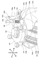
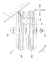
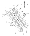
- the front wheel unit 12 includes a right front wheel 140, a left front wheel 142, a right front wheel brake 144, a left front wheel brake 146, a brake equalizer 148, a motor 150, a gearbox 152, and a deadman brake. It is equipped with 154, a right headlight 156, and a left headlight 158.
- the right front wheel 140 is connected to the gearbox 152 via the right drive shaft 160 (see FIGS. 21 and 22).
- the right side drive shaft 160 extends in the right side axle case 162 in the left-right direction, and is rotatably supported by the right side axle case 162 via a bearing (not shown).
- the right axle case 162 is held by the right frame pipe 132 via a right bracket 164 welded to the right frame pipe 132.
- the left front wheel 142 is connected to the gearbox 152 via the left drive shaft 166 (see FIGS. 21 and 22).
- the left side drive shaft 166 extends in the left side axle case 168 in the left-right direction, and is rotatably supported by the left side axle case 168 via a bearing (not shown).
- the left axle case 168 is held by the left frame pipe 134 via a left bracket 170 welded to the left frame pipe 134.
- the right axle case 162, the right bracket 164, the left axle case 168, and the left bracket 170 are all made of steel.
- the right front wheel brake 144 includes a disc rotor 172 and a brake caliper 174.
- the disc rotor 172 is arranged on the left side of the right front wheel 140 and is fixed to the right front wheel 140 via the hub 140a.
- the brake caliper 174 is arranged corresponding to the disc rotor 172.
- the brake caliper 174 is held by the right bracket 164.
- a right brake cable 176 is connected to the brake caliper 174.
- the right brake cable 176 includes an inner cable 176a and an outer cable 176b that covers the periphery of the inner cable 176a.
- the right front wheel brake 144 may be a so-called disc brake as described above, may be another type of brake, for example, a drum brake, or may be a band brake.
- the left front wheel brake 146 is equipped with a disc rotor 178 and a brake caliper 180.
- the disc rotor 178 is arranged on the right side of the left front wheel 142 and is fixed to the left front wheel 142 via the hub 142a.
- the brake caliper 180 is arranged corresponding to the disc rotor 178.
- the brake caliper 180 is held by the left bracket 170.
- a left brake cable 182 is connected to the brake caliper 180.
- the left brake cable 182 includes an inner cable 182a and an outer cable 182b that covers the periphery of the inner cable 182a.
- the left front wheel brake 146 may be a so-called disc brake as described above, may be another type of brake, for example, a drum brake, or may be a band brake.
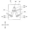
- the brake equalizer 148 includes a central bracket 184, a first link member 186, and a second link member 188.
- the central bracket 184 is made of steel, and the first link member 186 and the second link member 188 are both made of aluminum.
- the central bracket 184 is welded near the center of the central frame pipe 136.
- the first link member 186 and the second link member 188 are rotatably held by the central bracket 184 via a rotation shaft 190 extending in the vertical direction.
- the first link member 186 includes an input arm 186a extending from the rotation shaft 190 to the right front and an output arm 186b extending from the rotation shaft 190 to the right rear.
- the inner cable 94a of the brake cable 94 extending from the brake lever 49 of the left handle 20 is connected to the tip of the input arm 186a.
- the inner cable 176a of the right brake cable 176 is connected to the tip of the output arm 186b.
- the second link member 188 includes an input arm 188a extending from the rotation shaft 190 to the right front and an output arm 188b extending from the rotation shaft 190 to the left rear.
- the outer cable 94b of the brake cable 94 extending from the brake lever 49 of the left handle 20 is connected to the tip of the input arm 188a.
- the inner cable 182a of the left brake cable 182 is connected to the tip of the output arm 188b.
- the outer cable 176b of the right brake cable 176 and the outer cable 182b of the left brake cable 182 are both fixed to the central bracket 184.
- the first link member 186 and the second link member 188 may be rotatably held by the central bracket 184 via a rotation shaft extending in the left-right direction or the front-rear direction. ..
- the distance from the rotation shaft 190 to the tip of the input arm 186a, the distance from the rotation shaft 190 to the tip of the output arm 186b, and the angle formed by the input arm 186a and the output arm 186b are respectively.
- the distance from the rotating shaft 190 to the tip of the input arm 188a, the distance from the rotating shaft 190 to the output arm 188b, and the angle formed by the input arm 188a and the output arm 188b in the second link member 188 are substantially the same. Is.
- the right front wheel brake 144 and the left front wheel brake 146 may operate differently. For example, when the inner cable 94a of the brake cable 94 is pulled in relative to the outer cable 94b, the brake pad of the right front wheel brake 144 abuts on the disc rotor 172, and the brake pad of the left front wheel brake 146 is the disc rotor. It may not come into contact with 178.
- the brake equalizer 148 of the present embodiment the tension imbalance acting on the right side brake cable 176 and the left side brake cable 182 due to the respective rotational movements of the first link member 186 and the second link member 188. Can be absorbed, and the braking force applied to the right front wheel brake 144 and the braking force applied to the left front wheel brake 146 can be balanced.
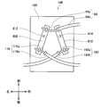
- the brake equalizer 148 may have a configuration as shown in FIG. 56.
- the brake equalizer 148 includes a central bracket 184, a first link member 802, and a second link member 804.
- the front end of the first link member 802 and the front end of the second link member 804 are rotatably held by the central bracket 184 via a rotation shaft 806 extending in the vertical direction.
- the inner cable 182a of the left brake cable 182 is connected to the rear end of the first link member 802.
- An inner cable 176a of the right brake cable 176 is connected to the rear end of the second link member 804.
- the outer cable 176b of the right brake cable 176 and the outer cable 182b of the left brake cable 182 are both fixed to the central bracket 184.
- An inner cable 94a of the brake cable 94 is connected to the vicinity of the center of the first link member 802.
- the outer cable 94b of the brake cable 94 is connected to the vicinity of the center of the second link member 804.
- the distance from the rotating shaft 806 to the holding position of the inner cable 94a in the first link member 802 and the distance from the rotating shaft 806 to the holding position of the inner cable 182a are the rotations in the second link member 804, respectively.
- the distance from the shaft 806 to the holding position of the outer cable 94b and the distance from the rotating shaft 806 to the holding position of the inner cable 176a are substantially the same.
- the imbalance of tension acting on the right side brake cable 176 and the left side brake cable 182 can be absorbed by the rotational movements of the first link member 802 and the second link member 804, respectively.
- the braking force applied to the right front wheel brake 144 and the braking force applied to the left front wheel brake 146 can be balanced.
- the brake equalizer 148 may have a configuration as shown in FIG. 57.
- the brake equalizer 148 includes a central bracket 184, a first link member 808, and a second link member 810.
- the first link member 808 is rotatably held by the central bracket 184 via a rotation shaft 812 extending in the vertical direction.
- the second link member 810 is rotatably held by the central bracket 184 via a rotation shaft 814 extending in the vertical direction.
- An inner cable 176a of the right brake cable 176 is connected to the rear end of the first link member 808.
- An inner cable 182a of the left brake cable 182 is connected to the rear end of the second link member 810.
- the outer cable 176b of the right brake cable 176 and the outer cable 182b of the left brake cable 182 are both fixed to the central bracket 184.
- the inner cable 94a of the brake cable 94 is connected to the front end of the first link member 808.
- the outer cable 94b of the brake cable 94 is connected to the front end of the second link member 810.
- the distance from the rotating shaft 812 to the holding position of the inner cable 94a in the first link member 808 and the distance from the rotating shaft 812 to the holding position of the inner cable 176a are the rotations in the second link member 810, respectively.
- the distance from the shaft 814 to the holding position of the outer cable 94b and the distance from the rotating shaft 814 to the holding position of the inner cable 182a are substantially the same.
- the right front wheel 140 and the left front wheel 142 are braked, respectively.
- the imbalance of tension acting on the right side brake cable 176 and the left side brake cable 182 can be absorbed by the rotational movements of the first link member 808 and the second link member 810, respectively.
- the braking force applied to the right front wheel brake 144 and the braking force applied to the left front wheel brake 146 can be balanced.
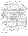
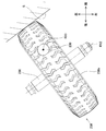
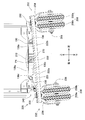
- the motor 150 includes a stator 192, a rotor 194, and a motor case 196.
- the motor 150 is, for example, a brushless DC motor.
- the stator 192 and rotor 194 are housed in a motor case 196.
- the motor case 196 is made of an aluminum material.
- the stator 192 is fixed to the motor case 196.
- the rotor 194 is fixed to the motor shaft 198.
- the motor shaft 198 extends in the left-right direction and is rotatably held by the motor case 196 via bearings 198a and 198b. The left end of the motor shaft 198 is connected to the gearbox 152.
- the right end of the motor shaft 198 projects to the outside of the motor case 196 and is connected to the deadman brake 154.
- the motor 150 is connected to the battery box 8 via a power cable (not shown). Power is supplied to the motor 150 from the battery pack 112. The operation of the motor 150 is controlled by the control board 108.
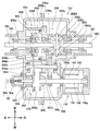
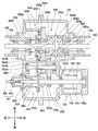
- the gearbox 152 includes a gear case 200, an intermediate shaft 202, a clutch mechanism 206, and a differential mechanism 208.
- the gear case 200 is made of an aluminum material.
- the right axle case 162, the left axle case 168, and the gear case 200 are screwed and fixed.
- the motor case 196 is screwed and fixed to the gear case 200.
- the gear case 200 is screwed and fixed to the central bracket 184 of the central frame pipe 136 via a support bracket (not shown).
- the intermediate shaft 202 extends in the left-right direction and is rotatably held by the gear case 200 via bearings 202a and 202b.
- the intermediate shaft 202 includes a first gear 203, a second gear 204, and a dog clutch 205.
- the first gear 203 is fixed to the intermediate shaft 202.
- the first gear 203 meshes with the spur gear 198c provided on the motor shaft 198.
- the first gear 203 includes an engaging recess 203a that is recessed to the right.
- the second gear 204 is immovable in the left-right direction with respect to the intermediate shaft 202 and is held rotatably.
- the dog clutch 205 is movable in the left-right direction with respect to the second gear 204 and is held so as not to rotate.
- the dog clutch 205 projects to the right and includes an engaging convex portion 205a that can engage with the engaging concave portion 203a of the first gear 203 and an engaging groove 205b that extends in the circumferential
- the clutch mechanism 206 includes a clutch lever 210, a support bracket 212, a rod 214, and a selector 216.
- the clutch lever 210 and the support bracket 212 are provided outside the gear case 200.
- the support bracket 212 is screwed and fixed to the gear case 200.
- the clutch lever 210 is rotatably held around the rotation shaft 210a by the support bracket 212.
- the clutch lever 210 includes a cam surface 210b.
- the rod 214 extends in the left-right direction and penetrates the gear case 200 from the inside to the outside.
- the rod 214 is held in the gear case 200 so as to be slidable in the left-right direction.
- the left end of the rod 214 is arranged so as to face the cam surface 210b of the clutch lever 210.
- a selector 216 is fixed to the right end of the rod 214, and the selector 216 is engaged with the engagement groove 205b of the dog clutch 205.
- the rod 214 is urged to the left with respect to the gear case 200 by a compression spring (not shown). Therefore, the left end of the rod 214 is always in contact with the cam surface 210b of the clutch lever 210.
- the cam surface 210b of the clutch lever 210 is in a state where the rod 214 moves to the left when the clutch lever 210 is pushed down with respect to the support bracket 212 (see FIG. 21), and the clutch lever 210 is raised with respect to the support bracket 212. (See FIG. 22), the rod 214 has a shape that moves to the right side.
- the differential mechanism 208 includes a ring gear 208a, a pinion case 208b, a pinion shaft 208c, a pinion gear 208d, a right side drive gear 208e, and a left side drive gear 208f.
- the ring gear 208a meshes with the second gear 204 of the intermediate shaft 202.
- the pinion case 208b is screwed and fixed to the ring gear 208a, and rotates integrally with the ring gear 208a.
- the ring gear 208a is rotatably held in the gear case 200 via the bearing 208g
- the pinion case 208b is rotatably held in the gear case 200 via the bearing 208h.
- the pinion shaft 208c is rotatably held in the pinion case 208b.
- the pinion gear 208d is fixed to the pinion shaft 208c.
- the right side drive gear 208e is fixed to the right side drive shaft 160 and meshes with the pinion gear 208d.
- the left drive gear 208f is fixed to the left drive shaft 166 and meshes with the pinion gear 208d.
- the deadman brake 154 includes a disc rotor 218 and a brake caliper 220.
- the disc rotor 218 is fixed to the right end of the motor shaft 198 of the motor 150.
- the disc rotor 218 is surrounded by a disc cover 218a (see FIGS. 21 and 22) fixed to the motor case 196.
- the brake caliper 220 is arranged corresponding to the disc rotor 218.
- the brake caliper 220 is held in the motor case 196.
- a deadman cable 90 extending from the right handle 18 is connected to the brake caliper 220.
- the brake caliper 220 uses a return spring (not shown) to urge a pair of brake pads (not shown) in a direction of sandwiching the vicinity of the outer edge of the disc rotor 218. Therefore, when the inner cable 90a of the deadman cable 90 is extruded relative to the outer cable 90b, the pair of brake pads sandwich the vicinity of the outer edge of the disc rotor 218, thereby exerting a frictional force on the disc rotor 218. Let it act to brake the motor shaft 198. When the inner cable 90a of the deadman cable 90 is pulled in relative to the outer cable 90b, the pair of brake pads separate from the disc rotor 218 against the urging force of the return spring, and the brake of the motor shaft 198 is released. Will be done.
- the deadman brake 154 may be a so-called disc brake as described above, may be another type of brake, for example, a drum brake, or may be a band brake.
- the motor shaft 198 When the right front wheel 140 and the left front wheel 142 are rotated by the power of the motor 150, the motor shaft 198 is rotating at a high rotation speed and a low torque, and the right drive shaft 160 and the left drive shaft 166 are rotating at a low rotation speed. It is rotating with high torque. Therefore, compared to the case where the right front wheel brake 144 applies the brake to the right front wheel 140 and the case where the left front wheel brake 146 applies the brake to the left front wheel 142, the case where the deadman brake 154 brakes the motor shaft 198 causes braking. Since the torque required for the brake is small, the rotation of the right front wheel 140 and the left front wheel 142 can be reliably stopped.
- the motor 150, the gearbox 152, and the deadman brake 154 may have the configurations shown in FIGS. 58 and 59. In this configuration, the right end of the motor shaft 198 does not project to the outside of the motor case 196. A brake disc 850 is fixed to the left end of the motor shaft 198.
- the gear box 152 includes a gear case 200, a relay shaft 852, a differential mechanism 208, a differential lock mechanism 854, and a brake mechanism 856.
- the brake disc 850 and the brake mechanism 856 constitute the deadman brake 154.
- the relay shaft 852 extends in the left-right direction and is rotatably held by the gear case 200 via bearings 852a and 852b.
- the relay shaft 852 includes a spur gear 852c and a spur gear 852d.
- the spur gear 852c meshes with the spur gear 198c provided on the motor shaft 198.
- the spur gear 852d meshes with the ring gear 208a of the differential mechanism 208.
- the differential lock mechanism 854 includes a dog clutch 858 and a compression spring 860.
- the dog clutch 858 is held by the left drive shaft 166 so as to be slidable in the left-right direction with respect to the left drive shaft 166 and to rotate integrally with the left drive shaft 166.
- the dog clutch 858 includes an engaging convex portion 858a projecting to the right and an engaging groove 858b extending in the circumferential direction on the outer peripheral surface.
- the ring gear 208a of the differential mechanism 208 is formed with an engaging recess 208i to which the engaging convex portion 858a of the dog clutch 858 can be engaged.
- the compression spring 860 urges the dog clutch 858 with respect to the gear case 200 toward the right (that is, toward the ring gear 208a).
- the brake mechanism 856 includes a rod 862, a brake plate 864, and a compression spring 866.
- the rod 862 extends in the left-right direction and penetrates the gear case 200 from the inside to the outside.
- the rod 862 is held in the gear case 200 so as to be slidable in the left-right direction.
- the inner cable 90a of the deadman cable 90 is connected to the left end of the rod 862.
- the outer cable 90b of the deadman cable 90 is connected to the gear case 200.
- a brake plate 864 is fixed to the right end of the rod 862.
- the brake plate 864 is provided with a brake shoe 864a arranged corresponding to the brake disc 850 and a selector 864b that engages with the engagement groove 858b of the dog clutch 858.
- the compression spring 866 urges the brake plate 864 with respect to the gear case 200 toward the right (that is, toward the direction closer to the brake disc 850).
- the ring gear 208a is fixed to the left drive shaft 166, and the right drive shaft 160 and the left drive shaft 166 rotate in the same direction at the same rotation speed.
- the deadman brake 154 brakes the rotation of the motor shaft 198, thereby braking the rotation of the ring gear 208a, thereby also braking the rotation of the right drive shaft 160 and the left drive shaft 166.
- the right headlight 156 is held by the right bracket 164.
- the right headlight 156 is connected to the battery box 8 via a power supply cable 156a.
- the left headlight 158 is held by the left bracket 170.
- the left headlight 158 is connected to the right headlight 156 via a relay cable 158a. Power is supplied to the right headlight 156 and the left headlight 158 from the battery pack 112. The operation of the right headlight 156 and the left headlight 158 is controlled by the control board 108.
- the rear wheel unit 14 includes a base plate 222, a hinge 224, a right caster 226, and a left caster 228. Both the base plate 222 and the hinge 224 are made of steel.
- the base plate 222 includes a web 222a along the front-rear direction and the left-right direction, a front flange 222b bent downward from the front end of the web 222a, and a rear flange 222c bent downward from the rear end of the web 222a.
- the hinge 224 includes a support pipe 224a extending in the front-rear direction, a front support plate 224b along the vertical and horizontal directions, and a rear support plate 224c along the vertical and horizontal directions.
- the front support plate 224b is formed in a substantially triangular shape, and is welded to the vicinity of the front end of the support pipe 224a with the support pipe 224a penetrating the center.
- the rear support plate 224c is formed in a substantially triangular shape, and is welded to the vicinity of the rear end of the support pipe 224a with the support pipe 224a penetrating the center.
- the lower end of the front support plate 224b and the lower end of the rear support plate 224c are welded to the upper surface of the web 222a of the base plate 222.
- the base plate 222 and the hinge 224 are collectively referred to as a rear wheel frame 225.
- the right caster 226 includes a center pin 230, a top plate 232, a bracket 234, a wheel shaft 236, a right rear wheel 238, and a lock mechanism 240.
- the center pin 230 penetrates the web 222a of the base plate 222 in the vertical direction.
- the center pin 230 is rotatably held by the top plate 232 via the bearing 230a.
- the top plate 232 is screwed and fixed to the base plate 222 in a state where the upper surface of the top plate 232 is in contact with the lower surface of the web 222a of the base plate 222.
- the bracket 234 includes a retainer 234a, a right arm 234b, and a left arm 234c.
- the retainer 234a, the right arm 234b, and the left arm 234c are integrally formed.
- the center pin 230 penetrates the retainer 234a in the vertical direction.
- the retainer 234a is fixed to the lower end of the center pin 230.
- the retainer 234a is rotatably held by the top plate 232 via a bearing 234d.
- the right arm 234b extends rearwardly and downwardly from the right end of the retainer 234a.
- the left arm 234c extends rearwardly and downwardly from the left end of the retainer 234a.
- the wheel shaft 236 extends in the left-right direction.
- the wheel shaft 236 is composed of a bolt 236a penetrating from the tip side of the left arm 234c to the tip side of the right arm 234b and a nut 236b screwed into the bolt 236a from the tip side of the right arm 234b.
- the right end of the wheel shaft 236 is fixed to the tip of the right arm 234b, and the left end of the wheel shaft 236 is fixed to the tip of the left arm 234c.
- the right rear wheel 238 includes a first right rear wheel 238a and a second right rear wheel 238b.
- the first right rear wheel 238a is rotatably held by the wheel shaft 236 via a bearing 238c.
- the second right rear wheel 238b is rotatably held by the wheel shaft 236 via a bearing 238d. That is, the first right rear wheel 238a and the second right rear wheel 238b can rotate around the rotation axis RX2, which is the central axis of the wheel shaft 236, independently of each other.
- the diameter of the first right rear wheel 238a and the second right rear wheel 238b is, for example, 200 mm, and the width of the first right rear wheel 238a and the second right rear wheel 238b is, for example, 100 mm.
- the distance between the first right rear wheel 238a and the second right rear wheel 238b is, for example, 6 mm ⁇ 2 mm.
- the wheel shaft 236 penetrates from the tip side of the left arm 234c to the tip side of the right arm 234b, and the sleeve 236c having a female screw formed on the inner surface and the tip of the right arm 234b. It may be composed of a bolt 236d screwed into the sleeve 236c from the side and a bolt 236e screwed into the sleeve 236c from the tip side of the left arm 234c. As shown in FIG.
- the bracket 234, the wheel shaft 236, and the right rear wheel 238 rotate integrally with respect to the top plate 232 around the rotation shaft RX1 which is the central axis of the center pin 230. Therefore, the traveling direction of the right rear wheel 238 can be changed according to the traveling direction of the rear wheel unit 14.
- the rotation axis RX2 which is the central axis of the wheel shaft 236, is offset from the rotation axis RX1 which is the central axis of the center pin 230. Is arranged.
- the distance from the rotating shaft RX1 to the rotating shaft RX2 when the right caster 226 is viewed from above is in the range of, for example, 50 mm to 60 mm, and is, for example, 55 mm.
- the lock mechanism 240 includes a lock pin 242, a support plate 244, and a compression spring 246.
- the lock pin 242 is a rod-shaped member having a substantially L shape.
- the lock pin 242 includes a first shaft portion 242a extending in the vertical direction and a second shaft portion 242b bent from the upper end of the first shaft portion 242a.
- the support plate 244 is screwed and fixed to the upper surface of the web 222a of the base plate 222. As shown in FIG. 29, the support plate 244 includes a through hole 244a through which the first shaft portion 242a of the lock pin 242 penetrates in the vertical direction.
- a first holding portion 244b that holds the second shaft portion 242b of the lock pin 242 at the first height and a second shaft portion 242b of the lock pin 242 are lower than the first height.
- a second holding portion 244c that holds at the second height is formed. As shown in FIG. 27, the compression spring 246 urges the lock pin 242 downward with respect to the support plate 244.
- the top plate 232 is formed with a through hole 232a through which the first shaft portion 242a of the lock pin 242 penetrates.
- engagement grooves 234e to which the first shaft portion 242a of the lock pin 242 engages are arranged at predetermined angular intervals.
- the first shaft portion 242a of the lock pin 242 penetrates the top plate 232. Although it penetrates the hole 232a, it is not engaged with the engaging groove 234e of the bracket 234.
- the bracket 234, the wheel shaft 236, and the right rear wheel 238 are allowed to rotate integrally with respect to the top plate 232.
- the position of the lock pin 242 in this state is also referred to as an unlock position.
- the first shaft portion 242a of the lock pin 242 penetrates the top plate 232. It penetrates the hole 232a and further engages with the engagement groove 234e of the bracket 234. In this state, the integral rotation operation of the bracket 234, the wheel shaft 236, and the right rear wheel 238 with respect to the top plate 232 is prohibited.
- the position of the lock pin 242 in this state is also referred to as a lock position.
- the user of the transport vehicle 2 integrally rotates the bracket 234, the wheel shaft 236, and the right rear wheel 238 with respect to the top plate 232. Can be switched between the prohibited state and the allowed state.
- FIG. 32 shows the positional relationship between the center pin 230, the wheel shaft 236, and the wheel 238e when the right caster 226 is viewed from above in the case where the right rear wheel 238 has only a single wheel 238e. Shown. For example, when the right rear wheel 238 collides diagonally with respect to the step S, the wheel shaft 236 and the wheel 238e rotate so that the traveling direction of the wheel 238e is in the direction facing the step S, as shown in FIG. If it moves, it becomes easy to get over the step S. However, with respect to the step S as shown in FIG.
- the direction of the torque T due to the force received by the wheel 238e from the step S acts in the direction opposite to the above-mentioned rotation direction, and therefore, as shown in FIG. ,
- the wheel 238e rotates so that the side surface of the wheel 238e hits the step S. If the wheel 238e rotates in this way, it will not be possible to get over the step S.
- the right rear wheel 238 includes a first right rear wheel 238a and a second right rear wheel 238b.
- the traveling directions of the first right rear wheel 238a and the second right rear wheel 238b are in the direction facing the step S, as shown in FIG. 35.
- the direction of the torque T due to the force received by the second right rear wheel 238b acts on the step S as shown in FIG. 34 in the same direction as the above-mentioned rotation direction, so that the step S is overcome. It can be made easier.
- the first right rear wheel 238a and the second right rear wheel 238b can rotate independently of the wheel shaft 236. Therefore, as shown in FIG. 34, when the right rear wheel 238 collides diagonally with the step S, for example, when the second right rear wheel 238b abuts on the step S, it does not abut on the step S.
- the traveling direction of the right rear wheel 238 can be easily changed to the direction facing the step S. And can easily get over the step S.
- the left caster 228 Like the right caster 226, the left caster 228 includes a center pin 250, a top plate 252, a bracket 254, a shaft 256, a left rear wheel 258, and a locking mechanism 260.
- the bracket 254 includes a retainer 254a, a right arm 254b, and a left arm 254c.
- the left rear wheel 258 includes a first left rear wheel 258a and a second left rear wheel 258b.
- the lock mechanism 260 includes a lock pin 262, a support plate 264, and a compression spring 266. Since the configuration of the left caster 228 is the same as that of the right caster 226 inverted left and right, detailed description thereof will be omitted.
- FIG. 36 (Connecting part of rear wheel unit 14 and chassis frame 10) As shown in FIG. 36, the rear wheel unit 14 is connected to the chassis frame 10 via a connecting shaft 270 extending in the front-rear direction.
- a connecting pipe 272 and a support plate 274 are welded to the lower surface of the frame plate 130 of the chassis frame 10.
- the connecting pipe 272 extends in the front-rear direction, the front end penetrating the support plate 274, and the rear end penetrating the rear flange 130c.
- the connecting shaft 270 includes a head portion 270a and a shaft portion 270b.
- the shaft portion 270b of the connecting shaft 270 is inserted into the support pipe 224a of the rear wheel unit 14 from the rear and penetrates the support pipe 224a, and further penetrates the connecting pipe 272 of the chassis frame 10.
- the front end of the connecting shaft 270 is fixed to the support plate 274 by connecting pins 276.
- the support pipe 224a is slidable with respect to the connecting shaft 270. Therefore, as shown in FIG. 38, the rear wheel unit 14 is held by the chassis frame 10 so as to be swingable around the swing shaft PX, which is the central axis of the connecting shaft 270. With such a configuration, when the transport vehicle 2 travels on rough terrain, the rear wheel unit 14 swings with respect to the chassis frame 10, so that the followability to the road surface can be improved. Further, as shown in FIG. 10, when the chassis unit 4 is viewed from the rear in a plan view, the swing axis PX of the rear wheel unit 14 is from a straight line L passing through the upper end of the right rear wheel 238 and the upper end of the left rear wheel 258. Is also located above.
- the rear flange 130c of the chassis frame 10 has a right stopper surface 130d arranged on the right side of the connecting shaft 270 and a left stopper surface 130e arranged on the left side of the connecting shaft 270. Is formed.
- the right stopper surface 130d has a shape from the bottom to the top as it goes from the left to the right.
- the right stopper surface 130d abuts on the floor plate 130a of the chassis frame 10 when the rear wheel unit 14 swings with respect to the chassis frame 10 in the direction in which the right rear wheel 238 moves upward.
- the swing angle of the unit 14 with respect to the chassis frame 10 is limited.
- the left stopper surface 130e has a shape from downward to upward as it goes from right to left.
- the left stopper surface 130e comes into contact with the floor plate 130a of the chassis frame 10 when the rear wheel unit 14 swings with respect to the chassis frame 10 in the direction in which the left rear wheel 258 moves upward.
- the swing angle of the unit 14 with respect to the chassis frame 10 is limited.
- the rear wheel unit 14 may be held by the chassis frame 10 so as not to swing around the swing axis PX with respect to the chassis frame 10.
- the right front wheel 140 and the left front wheel 142 are driving wheels, and the right rear wheel 238 and the left rear wheel 258 are non-driving wheels.
- the right front wheel 140 and / or the left front wheel 142 may be non-driving wheels, and the right rear wheel 238 and / or left rear wheel 258 may be driving wheels.
- one of the front wheel unit 12 and the rear wheel unit 14 may have only one wheel, and the other of the front wheel unit 12 and the rear wheel unit 14 may have a plurality of wheels.
- the chassis unit 4 may not include the rear wheel unit 14, and the front wheel unit 12 may include only one drive wheel.
- the chassis unit 4 may include a motor-driven crawler instead of the right front wheel 140, the left front wheel 142, the right rear wheel 238 and the left rear wheel 258.
- the prime mover for rotating the drive wheels is the motor 150, and the motor 150 is driven by the electric power from the battery pack 112 of the battery box 8.
- the prime mover that rotates the drive wheels may be an engine.
- the motor 150 may be driven by electric power supplied from an external power source via a cord.
- the motor 150 may be a motor other than a brushless motor, such as a brushed motor.
- the motor 150 may be an in-wheel motor provided for each drive wheel.
- the chassis unit 4 of the present embodiment extends in the vertical direction on the right side and the left side of the operator, the upper ends of the chassis units 4 are bent rearward, and the grips 38 and 48 are provided at the rear ends of the right handle. It has 18 and a left handle 20.
- the chassis unit 4 has a so-called loop shape in which support portions extend vertically on the right side and left side of the operator, and the upper ends of the support portions are connected by grip portions extending in the left-right direction. It may be provided with a handle of.
- the taillight 74 may be provided on the right and left support portions of the operator, or may be provided near the left-right end of the grip portion extending in the left-right direction.
- the chassis unit 4 may have a so-called T-shaped handle in which the support portion extends in the vertical direction at the center in the left-right direction and the upper end of the support portion is connected to the grip portion extending in the left-right direction.
- the taillight 74 may be provided near the left-right end of the grip portion extending in the left-right direction.
- the first loading platform unit 300 includes a loading platform 302, a right side guard 304, a left side guard 306, a front side guard 308, a rear side guard 310, a first arm 312, and a second. It includes an arm 314, an actuator 316, and a support base 318.
- the support base 318 is fixed to the chassis unit 4 by screwing. The first loading platform unit 300 can move the loading platform 302 in the vertical direction with respect to the support platform 318 by driving the actuator 316.
- the loading platform 302 includes a loading platform plate 320, a right channel 322, a left channel 324, a reinforcing channel 326, a right guard holding portion 328, and a left guard holding portion 330.
- the front guard holding portion 332 is provided.
- the loading platform plate 320, the right channel 322, the left channel 324, the reinforcing channel 326, the right guard holding portion 328, the left guard holding portion 330, and the front guard holding portion 332 are all made of steel.
- the loading platform plate 320 has a substantially rectangular top plate 320a having a longitudinal direction in the front-rear direction along the front-rear direction and the left-right direction, a right flange 320b bent downward from the right end of the top plate 320a, and a top plate 320a. It includes a left side flange 320c bent downward from the left end, a front flange 320d bent downward from the front end of the top plate 320a, and a rear flange 320e bent downward from the rear end of the top plate 320a.
- the upper surface of the top plate 320a constitutes a flat mounting surface.
- the right channel 322 and the left channel 324 extend in the front-rear direction between the front flange 320d and the rear flange 320e along the lower surface of the top plate 320a and are welded to the loading platform plate 320.
- the right channel 322 has a cross-sectional shape that opens toward the left side
- the left channel 324 has a cross-sectional shape that opens toward the right side.
- the reinforcing channel 326 extends laterally along the lower surface of the top plate 320a between the right flange 320b and the right channel 322 and between the left flange 320c and the left channel 324 and is welded to the carrier plate 320. There is.
- the right guard holding portion 328 is welded to the right surface of the right flange 320b.
- the right guard holding portion 328 is arranged near the connection point between the reinforcing channel 326 and the right flange 320b.
- the left guard holding portion 330 is welded to the left surface of the left flange 320c.
- the left guard holding portion 330 is arranged near the connection portion between the reinforcing channel 326 and the left flange 320c.
- the front guard holding portion 332 is welded to the front surface of the front flange 320d.
- the front guard holding portion 332 is arranged near the connection point between the right side channel 322 and the front side flange 320d, and near the connection point between the left side channel 324 and the front side flange 320d.
- the right guard 304 includes a guard pipe 304a and a support pipe 304b. Both the guard pipe 304a and the support pipe 304b are made of steel.
- the guard pipe 304a extends in the front-rear direction and bends downward at the front end and the rear end.
- the support pipe 304b extends in the vertical direction, and the upper end thereof is welded to the lower surface of the guard pipe 304a.
- the left guard 306 includes a guard pipe 306a and a support pipe 306b. Both the guard pipe 306a and the support pipe 306b are made of steel.
- the guard pipe 306a extends in the front-rear direction and bends downward at the front end and the rear end.
- the support pipe 306b extends in the vertical direction, and the upper end thereof is welded to the lower surface of the guard pipe 306a.
- the front guard 308 includes a guard pipe 308a and a support pipe 308b. Both the guard pipe 308a and the support pipe 308b are made of steel.
- the guard pipe 308a extends in the left-right direction and bends downward at the right end and the left end.
- the support pipe 308b extends in the vertical direction, and the upper end thereof is welded to the lower surface of the guard pipe 308a.
- the rear guard 310 includes a guard pipe 310a and a guard plate 310b. Both the guard pipe 310a and the guard plate 310b are made of steel.
- the guard pipe 310a extends in the left-right direction and bends downward at the right end and the left end, and the tips of the guard pipes 310a are fixed to the rear flange 320e of the loading platform plate 320.
- the guard plate 310b is along the vertical and horizontal directions, and the left and right ends are welded to the guard pipe 310a.
- the right guard holding portion 328 has a substantially square tubular shape, and includes an upper opening 328a and a lower opening 328b.
- the space inside the right guard holding portion 328 has a dimension in the left-right direction slightly larger than the outer diameter of the support pipe 304b of the right guard 304, and a dimension in the front-rear direction is more than twice the outer diameter of the support pipe 304b of the right guard 304. Is also big.
- Support plates 328c along the front-rear direction and the left-right direction are formed in the front lower portion of the right guard holding portion 328.
- a flange 328d bent upward is formed at the rear end of the support plate 328c.
- a right opening 328e continuously formed from the lower opening 328b is formed on the right surface of the right guard holding portion 328.
- a retaining screw 304c is attached near the lower end of the support pipe 304b of the right guard 304.
- the retaining screw 304c is attached to the support pipe 304b via the right opening 328e in a state where the support pipe 304b is inserted into the right guard holding portion 328 from above.
- the retaining screw 304c prevents the support pipe 304b from coming out of the right guard holding portion 328 by engaging with the edge of the right opening 328e when the support pipe 304b tries to come out above the right guard holding portion 328.
- a rubber 328f that suppresses damage due to contact with the support pipe 304b is provided on the inner surface of the right guard holding portion 328.
- the upper end of the guard pipe 304a is higher than the upper surface of the top plate 320a. At this position, it is held by the right guard holding portion 328. In this state, the right side guard 304 can prevent the load placed on the loading platform plate 320 from falling from the right side.
- the state of the right guard 304 shown in FIG. 42 is also referred to as a first state.
- the support pipe 304b penetrates the right guard holding portion 328 as shown in FIG. 43.
- the lower surface of the guard pipe 304a abuts on the edge of the upper opening 328a of the right guard holding portion 328.
- the right guard 304 is held by the right guard holding portion 328 at a position where the upper end of the guard pipe 304a is lower than the upper surface of the top plate 302a. In this state, the right guard 304 does not get in the way when loading and unloading the load on the loading platform plate 320, and the workability of loading and unloading can be improved.
- the state of the right guard 304 shown in FIG. 43 is also referred to as a second state. From the second state shown in FIG. 43, when the right guard 304 is lifted upward, moved forward, and then moved downward, the first state shown in FIG. 42 can be obtained. In the first loading platform unit 300 of this embodiment, since the flange 328d is provided at the rear end of the support plate 328c, the right guard 304 unintentionally moves from the first state shown in FIG. 42 to the first state shown in FIG. 43. It will not be in two states.
- the height of the right guard 304 with respect to the loading platform plate 320 is changed by moving the right guard 304 in the front-rear direction and the vertical direction without moving the loading platform plate 320 in the left-right direction.
- the distance between the right guard 304 and the loading platform plate 320 when the first loading platform unit 300 is viewed from above in a plan view is 30 mm ⁇ 5 mm
- the distance between the right guard 304 and the loading platform plate 320 when the first loading platform unit 300 is viewed from above is 30 mm ⁇ 5 mm.
- the first loading platform unit 300 is used when shifting from the first state shown in FIG.
- the change in the distance between the right guard 304 and the loading platform plate 320 when viewed in a plan view from above is within a range of ⁇ 5 mm.
- the height of the right guard 304 with respect to the loading platform plate 320 can be changed even in a situation where a wide work space cannot be obtained in the left-right direction.
- the user can use the right side guard 304. Can be easily grasped.
- the height of the right side guard 304 with respect to the loading platform plate 320 can be changed without substantially changing the angle of the right side guard 304 with respect to the loading platform plate 320.
- the angle of the right side guard 304 with respect to the loading platform plate 320 is 90 degrees ⁇ 3 degrees
- the angle of the right side guard 304 with respect to the loading platform plate 320 is 90 degrees ⁇ 3. Degree.
- the loading platform plate of the right guard 304 when shifting from the first state shown in FIG. 42 to the second state shown in FIG. 43, and when shifting from the second state shown in FIG. 43 to the first state shown in FIG. 42, the loading platform plate of the right guard 304.
- the angle change with respect to 320 is within the range of ⁇ 3 degrees. With such a configuration, the height of the right guard 304 with respect to the loading platform plate 320 can be changed even in a situation where a wide work space cannot be obtained in the left-right direction.
- the left guard holding portion 330 has the same configuration as the right guard holding portion 328.
- the left guard 306 is held by the left guard holding portion 330 at a position where the upper end of the guard pipe 306a is higher than the upper surface of the top plate 320a. From this state, when the left side guard 306 is lifted upward, moved backward, and then moved downward, as shown in FIG. 44, the left side guard 306 has the upper end of the guard pipe 306a on the top plate 302a. It is held by the left guard holding portion 330 at a position lower than the upper surface. From the state shown in FIG. 44, the state shown in FIG. 39 can be obtained by lifting the left guard 306 upward, moving it forward, and then moving it downward.
- the front guard holding portion 332 also has the same configuration as the right guard holding portion 328.
- the front guard 308 is held by the front guard holding portion 332 at a position where the upper end of the guard pipe 308a is higher than the upper surface of the top plate 320a. From this state, when the front guard 308 is lifted upward, moved to the left, and then moved downward, as shown in FIG. 44, the front guard 308 has a top plate 302a at the upper end of the guard pipe 308a. It is held by the front guard holding portion 332 at a position lower than the upper surface of the. From the state shown in FIG. 44, the state shown in FIG. 39 can be obtained by lifting the front guard 308 upward, moving it to the right, and then moving it downward.
- the support base 318 includes a right side channel 334, a left side channel 336, a front side plate 338, a rear side plate 340, and a reinforcing frame 342.
- the right channel 334, the left channel 336, the front plate 338, the rear plate 340, and the reinforcing frame 342 are all made of steel.
- the right channel 334 and the left channel 336 extend in the anteroposterior direction.
- the right channel 334 has a cross-sectional shape that opens toward the left side
- the left channel 336 has a cross-sectional shape that opens toward the right side.
- the front plate 338 is welded to the front end of the right channel 334 and the front end of the left channel 336, respectively.
- the rear plate 340 is welded to the rear end of the right channel 334 and the rear end of the left channel 336, respectively.
- the front side plate 338 is screwed to the right side bracket 164 and the left side bracket 170 of the front wheel unit 12, and the rear side plate 340 is screwed to the frame plate 130 of the chassis frame 10. By doing so, it is fixed to the chassis unit 4.
- the reinforcing frame 342 extends in the left-right direction and is welded to the right channel 334 at the right end and to the left channel 336 at the left end.
- the first arm 312 and the second arm 314 are rotatably connected to each other with the left-right direction as a rotation axis. Both the first arm 312 and the second arm 314 are made of steel.
- the lower end of the first arm 312 is rotatably held near the front end of the right channel 334 of the support base 318 and near the front end of the left channel 336 with the left and right directions as rotation axes.
- the upper end of the first arm 312 includes rollers 312a and 312b. The rollers 312a and 312b are held in the right channel 322 and the left channel 324 of the loading platform 302.
- the upper end of the second arm 314 is rotatably held in the vicinity of the front end of the loading platform plate 320 of the loading platform 302 with the left-right direction as a rotation axis.
- the lower end of the second arm 314 includes rollers 314a and 314b (see FIG. 40).
- the rollers 314a and 314b are held by the right channel 334 and the left channel 336 of the support base 318.
- a reinforcing frame 344 is welded to the first arm 312.
- the actuator 316 is a linear actuator capable of shortening and extending operations, for example, a hydraulic cylinder.
- One end of the actuator 316 is rotatably held by the reinforcing frame 342 of the support base 318 with the left-right direction as a rotation axis.
- the other end of the actuator 316 is rotatably held by the reinforcing frame 344 of the first arm 312 with the left-right direction as a rotation axis.
- the actuator 316 is connected to the battery box 8 via a power cable (not shown). Power is supplied to the actuator 316 from the battery pack 112. The operation of the actuator 316 is controlled by the control board 108.
- the first arm 312 rotates in the direction in which the upper end of the first arm 312 approaches the support base 318
- the second arm 314 rotates in the direction in which the lower end of the second arm 314 approaches the loading platform 302.
- the loading platform 302 descends with respect to the support platform 318, as shown in FIG. 39.
- the actuator 316 extends, the first arm 312 rotates in the direction in which the upper end of the first arm 312 moves away from the support base 318, and the second arm 314 rotates in the direction in which the lower end of the second arm 314 moves away from the loading platform 302.
- the loading platform 302 rises with respect to the support platform 318.
- the control board 108 controls the actuator 316 to execute the extension operation while the user presses the upper side of the loading platform operation switch 120e. Further, the control board 108 controls the actuator 316 to execute the shortening operation while the user presses the lower side of the loading platform operation switch 120e.
- the second loading platform unit 400 includes a bucket 402, a bucket support 404, a support arm 406, a movable support 408, an actuator 410, and a fixed support 412. I have.
- the fixed support base 412 is fixed to the chassis frame 10 by screwing.
- the second loading platform unit 400 can tilt the movable support platform 408 with respect to the fixed support platform 412 by driving the actuator 410, as shown in FIG.
- the bucket 402 when the user tilts the bucket support 404 with respect to the movable support 408, the bucket 402 can be further tilted with respect to the fixed support 412 as shown in FIG. 47. it can.
- the bucket 402 has a box shape with an opening at the top.
- the bucket support 404 includes a base plate 416, a base pipe 418, an upper frame 420, a lower frame 422, a handle 424, and a latch mechanism 426.
- the base plate 416, the base pipe 418, the upper frame 420, and the lower frame 422 are all made of steel.
- the base plate 416 is arranged along the front-rear direction and the left-right direction.
- the base pipe 418 extends along the lower surface of the lower front portion of the bucket 402 and extends in the front-rear direction along the lower surface of the base plate 416.
- the base pipe 418 is screwed to the lower front portion of the bucket 402 and is screwed to the base plate 416.
- the upper frame 420 is arranged along the front-rear direction and the up-down direction between the lower surface of the lower rear portion of the bucket 402 and the upper surface of the base plate 416.
- the upper frame 420 is screwed to the lower rear portion of the bucket 402 and is screwed to the base plate 416.
- the lower frame 422 extends in the front-rear direction along the lower surface of the base plate 416.
- the lower frame 422 is welded to the base plate 416.
- the handle 424 is arranged behind the bucket 402.
- the handle 424 is screwed to the lower frame 422.
- the latch mechanism 426 is provided below the handle 424.
- the latch mechanism 426 is fixed to the base plate 416 and the lower frame 422.
- the movable support base 408 includes a right side frame 428, a left side frame 430, a front side frame 432, a rear side frame 434, and a latch receiver 436.
- the right side frame 428, the left side frame 430, the front side frame 432, and the rear side frame 434 are all made of steel.
- the right frame 428 and the left frame 430 extend in the front-rear direction.
- the front end of the right frame 428 and the front end of the left frame 430 are rotatably connected to the front end of the lower frame 422 of the bucket support 404 with the left and right directions as rotation axes.
- the front frame 432 extends in the left-right direction between the vicinity of the front end of the right frame 428 and the vicinity of the front end of the left frame 430.
- the front frame 432 is welded to the right frame 428 and the left frame 430.
- the rear frame 434 extends in the left-right direction between the rear end of the right frame 428 and the rear end of the left frame 430.
- the rear frame 434 is welded to the right frame 428 and the left frame 430.
- the latch receiver 436 is fixed near the center of the rear frame 434.
- the latch receiver 436 is arranged at a position corresponding to the latch mechanism 426 of the bucket support 404.
- the latch mechanism 426 engages with the latch receiver 436.
- the latch mechanism 426 includes a latch release knob 426a. When the user operates the latch release knob 426a while the latch mechanism 426 is engaged with the latch receiver 436, the engagement between the latch mechanism 426 and the latch receiver 436 is released.
- the fixed support 412 includes a right channel 438, a left channel 440, a front plate 442, a rear plate 444, and a reinforcing frame 446.
- the right channel 438, the left channel 440, the front plate 442, the rear plate 444, and the reinforcing frame 446 are all made of steel.
- the right channel 438 and the left channel 440 extend in the anteroposterior direction.
- the right channel 438 has a cross-sectional shape that opens toward the left side
- the left channel 440 has a cross-sectional shape that opens toward the right side.
- the front plate 442 is welded to the front end of the right channel 438 and the front end of the left channel 440, respectively.
- the rear plate 444 is welded to the rear end of the right channel 438 and the rear end of the left channel 440, respectively.
- the front plate 442 is screwed to the right bracket 164 and the left bracket 170 of the front wheel unit 12, and the rear plate 444 is screwed to the frame plate 130 of the chassis frame 10. It is fixed to the chassis unit 4 by screwing to.
- the reinforcing frame 446 extends in the left-right direction and is welded to the right channel 438 at the right end and to the left channel 440 at the left end.
- the upper end of the support arm 406 is rotatably connected to the vicinity of the front end of the lower frame 422 of the bucket support base 404 with the left-right direction as a rotation axis.
- the support arm 406 is made of steel.
- the lower end of the support arm 406 includes rollers 406a and 406b. The rollers 406a and 406b are held by the right channel 438 and the left channel 440 of the fixed support 412.
- the actuator 410 is a linear actuator capable of shortening and extending operations, for example, a hydraulic cylinder.
- One end of the actuator 410 is rotatably held by the reinforcing frame 446 of the fixed support base 412 with the left-right direction as a rotation axis.
- the other end of the actuator 410 is rotatably held by the front frame 432 of the movable support base 408 with the left-right direction as a rotation axis.
- the actuator 410 is connected to the battery box 8 of the chassis unit 4 via a power cable (not shown). Power is supplied to the actuator 410 from the battery pack 112.
- the operation of the actuator 410 is controlled by the control board 108.
- the movable support 408 rotates with respect to the fixed support 412 in a direction in which the rear end of the movable support 408 approaches the rear end of the fixed support 412, as shown in FIG.
- the movable support base 408 and the bucket support base 404 are substantially parallel to the fixed support base 412.
- the actuator 410 extends, the movable support 408 rotates with respect to the fixed support 412 in a direction in which the rear end of the movable support 408 moves away from the rear end of the fixed support 412, as shown in FIG.
- the movable support base 408 and the bucket support base 404 are in an inclined state with respect to the fixed support base 412.
- the control board 108 controls the actuator 410 to execute the extension operation while the user presses the upper side of the loading platform operation switch 120e. Further, the control board 108 controls the actuator 410 to execute the shortening operation while the user presses the lower side of the loading platform operation switch 120e. From the state shown in FIG. 46, the user operates the latch release knob 426a to release the engagement between the latch mechanism 426 and the latch receiver 436, and further grasps the handle 424 and rotates it forward. As shown in FIG. 47, the bucket support 404 can be tilted with respect to the movable support 408.
- the third loading platform unit 500 includes a bucket 502, a movable support platform 504, a support arm 506, and a fixed support platform 508.
- the fixed support base 508 is fixed to the chassis unit 4 by screwing.
- the third loading platform unit 500 can tilt the bucket 502 with respect to the fixed support 508, as shown in FIG. 50, by tilting the movable support 504 with respect to the fixed support 508.
- the bucket 502 has a box shape with an opening at the top.
- the movable support base 504 includes a base plate 510, a base pipe 512, an upper frame 514, a lower frame 516, a handle 518, and a latch mechanism 520.
- the base plate 510, the base pipe 512, the upper frame 514, and the lower frame 516 are all made of steel.
- the base plate 510 is arranged along the front-rear direction and the left-right direction.
- the base pipe 512 extends along the lower surface of the lower front portion of the bucket 502 and extends in the front-rear direction along the lower surface of the base plate 510.
- the base pipe 512 is screwed to the lower front portion of the bucket 502 and is screwed to the base plate 510.
- the upper frame 514 is arranged along the front-rear direction and the up-down direction between the lower surface of the lower rear portion of the bucket 502 and the upper surface of the base plate 510.
- the upper frame 514 is screwed to the rear lower portion of the bucket 502 and is screwed to the base plate 510.
- the lower frame 516 extends in the front-rear direction along the lower surface of the base plate 510.
- the lower frame 516 is welded to the base plate 510.
- the handle 518 is arranged behind the bucket 502.
- the handle 518 is screwed to the lower frame 516.
- the latch mechanism 520 is provided below the handle 518.
- the latch mechanism 520 is fixed to the base plate 510 and the lower frame 516.
- the fixed support 508 includes a right channel 522, a left channel 524, a front plate 526, a rear plate 528, a reinforcing frame 530, and a latch receiver 532.
- the right channel 522, the left channel 524, the front plate 526, the rear plate 528, and the reinforcing frame 530 are all made of steel.
- the right channel 522 and the left channel 524 extend in the anteroposterior direction.
- the right channel 522 has a cross-sectional shape that opens toward the left side
- the left channel 524 has a cross-sectional shape that opens toward the right side.
- the front plate 526 is welded to the front end of the right channel 522 and the front end of the left channel 524, respectively.
- the rear plate 528 is welded to the rear end of the right channel 522 and the rear end of the left channel 524, respectively.
- the front plate 526 is screwed to the right bracket 164 and the left bracket 170 of the front wheel unit 12, and the rear plate 528 is screwed to the frame plate 130 of the chassis frame 10. It is fixed to the chassis unit 4 by screwing to.
- the reinforcing frame 530 extends in the left-right direction and is welded to the right channel 522 at the right end and to the left channel 524 at the left end.
- the latch receiver 532 is fixed near the center of the rear plate 528.
- the latch receiver 532 is arranged at a position corresponding to the latch mechanism 520 of the movable support base 504.
- the latch mechanism 520 includes a latch release knob 520a. When the user operates the latch release knob 520a while the latch mechanism 520 is engaged with the latch receiver 532, the engagement between the latch mechanism 520 and the latch receiver 532 is released.
- the upper end of the support arm 506 is rotatably connected to the vicinity of the front end of the lower frame 516 of the movable support base 504 with the left-right direction as a rotation axis.
- the support arm 506 is made of steel.
- the lower end of the support arm 506 includes rollers 506a and 506b. The rollers 506a and 506b are held by the right channel 522 and the left channel 524 of the fixed support 508.
- the user operates the latch release knob 520a to disengage the latch mechanism 520 and the latch receiver 532, and further grasps the handle 518 and rotates it forward.
- the movable support base 504 can be tilted with respect to the fixed support base 508.
- the fourth loading platform unit 600 includes a loading platform 602, a movable support platform 604, a support arm (not shown), and a fixed support platform 606.
- the fixed support base 606 is fixed to the chassis unit 4 by screwing.
- the fourth loading platform unit 600 can tilt the loading platform 602 with respect to the fixed support platform 606 by tilting the movable support platform 604 with respect to the fixed support platform 606.
- the loading platform 602 includes a main frame 608, a right side guard 610, a left side guard 612, and a front side guard 614.
- the main frame 608 includes a frame pipe 616, a floor pipe 618, a reinforcing pipe 620, a right side guard holding pipe 622, a left side guard holding pipe 624, and a front side guard holding pipe 626.
- the frame pipe 616, the floor pipe 618, the reinforcing pipe 620, the right side guard holding pipe 622, the left side guard holding pipe 624, and the front side guard holding pipe 626 are all made of steel.
- the frame pipe 616 is formed in a substantially rectangular shape having a longitudinal direction in the front-rear direction and a lateral direction in the left-right direction.
- the floor pipe 618 extends in the front-rear direction in substantially the same plane as the frame pipe 616, and the front end and the rear end are welded to the frame pipe 616.
- the reinforcing pipe 620 extends in the left-right direction along the lower surfaces of the frame pipe 616 and the floor pipe 618, and is welded to the frame pipe 616 and the floor pipe 618.
- the right guard holding pipe 622 extends in the left-right direction along the lower surfaces of the frame pipe 616 and the floor pipe 618 near the right end of the main frame 608, and is welded to the frame pipe 616 and the floor pipe 618.
- the left guard holding pipe 624 extends in the left-right direction along the lower surfaces of the frame pipe 616 and the floor pipe 618 near the left end of the main frame 608, and is welded to the frame pipe 616 and the floor pipe 618.
- the front guard holding pipe 626 extends in the front-rear direction along the lower surface of the floor pipe 618 near the front end of the main frame 608 and is welded to the floor pipe 618.
- a hook 616a projecting downward is provided on the lower surface of the frame pipe 616. The user can hook the rope on the hook 616a when the rope is hung on the load placed on the loading platform 602.
- the right guard 610 includes a guard pipe 628 and an insertion pipe 630. Both the guard pipe 628 and the insertion pipe 630 are made of steel.
- the guard pipe 628 is formed in a substantially rectangular shape having a longitudinal direction in the front-rear direction and a lateral direction in the vertical direction.
- the insertion pipe 630 extends in the left-right direction, and the right end is welded to the lower part of the guard pipe 628.
- the right guard 610 is held in the main frame 608 by inserting the insertion pipe 630 into the right guard holding pipe 622.
- the right guard holding pipe 622 includes a grip bolt 622a that fixes the position of the insertion pipe 630 with respect to the right guard holding pipe 622.
- the user adjusts the position of the right side guard 610 with respect to the main frame 608 in the left-right direction with the grip bolt 622a loosened, and then tightens the grip bolt 622a to move the right side guard 610 to the main frame 608 at a desired position. Can be fixed.
- the left guard 612 is provided with a guard pipe 632 and an insertion pipe 634. Both the guard pipe 632 and the insertion pipe 634 are made of steel.
- the guard pipe 632 is formed in a substantially rectangular shape having a longitudinal direction in the front-rear direction and a lateral direction in the vertical direction.
- the insertion pipe 634 extends in the left-right direction, and the left end is welded to the lower part of the guard pipe 632.
- the left guard 612 is held in the main frame 608 by inserting the insertion pipe 634 into the left guard holding pipe 624.
- the left guard holding pipe 624 includes a grip bolt 624a that secures the position of the insertion pipe 634 with respect to the left guard holding pipe 624.
- the user adjusts the position of the left guard 612 with respect to the main frame 608 in the left-right direction, and then tightens the grip bolt 624a to move the left guard 612 to the main frame 608 at the desired position.
- the front guard 614 includes a guard pipe 636 and an insertion pipe 638. Both the guard pipe 636 and the insertion pipe 638 are made of steel.
- the guard pipe 636 is formed in a substantially rectangular shape having a longitudinal direction in the left-right direction and a lateral direction in the vertical direction.
- the insertion pipe 638 extends in the front-rear direction, and its front end is welded to the lower part of the guard pipe 636.
- the front guard 614 is held in the main frame 608 by inserting the insertion pipe 638 into the front guard holding pipe 626.
- the front guard holding pipe 626 includes a grip bolt 626a that fixes the position of the insertion pipe 638 with respect to the front guard holding pipe 626.
- the user adjusts the position of the front guard 614 with respect to the main frame 608 in the front-rear direction, and then tightens the grip bolt 626a to move the front guard 614 to the main frame 608 at the desired position.
- the movable support base 604 includes a base plate 640, a lower frame 642, a handle 644, and a latch mechanism 646.
- the configuration of the base plate 640, the lower frame 642, the handle 644, and the latch mechanism 646 is the same as the configuration of the base plate 510 of the third loading platform unit 500, the lower frame 516, the handle 518, and the latch mechanism 520. ..
- the reinforcing pipe 620 of the main frame 608 is screwed to the base plate 640.
- the fixed support 606 includes a right channel 648, a left channel 650, a front plate 652, a rear plate 654, a reinforcing frame 656, and a latch receiver 658.
- the configuration of the fixed support base 606 is the same as the configuration of the fixed support base 508 of the third loading platform unit 500.
- the mode of connecting the movable support base 604 and the fixed support base 606 is the same as the mode of connecting the movable support base 504 and the fixed support base 508 of the third loading platform unit 500. That is, most of the parts of the fourth loading platform unit 600 are shared with the third loading platform unit 500.
- the user operates the latch release knob 646a to disengage the latch mechanism 646 and the latch receiver 658 from the state shown in FIG. 52, and further, the handle 644
- the movable support 604 can be tilted with respect to the fixed support 606 by grasping and rotating the movable support 604 forward.
- the fifth loading platform unit 700 includes a bucket 702 and a support platform 704.
- the support base 704 is fixed to the chassis unit 4 by screwing.
- the bucket 702 is not fixed to the support base 704, and the user can mount the bucket 702 on the support base 704 or lift the bucket 702 to remove it from the support base 704. You can also.
- the bucket 702 has a box shape with an upper opening.
- a through hole 702a is formed in the lower part of the front surface of the bucket 702.
- a cap 706 is detachably attached to the through hole 702a.
- the support 704 includes a central frame 708, a right channel 710, a left channel 712, a front plate 714, a rear plate 716, a right guard 718, and a left guard 720. ..
- the central frame 708, the right channel 710, the left channel 712, the front plate 714, and the rear plate 716 are all made of steel.
- the central frame 708, the right channel 710, and the left channel 712 extend in the anteroposterior direction.
- the front plate 714 is welded to the front end of the central frame 708, the front end of the right channel 710, and the front end of the left channel 712, respectively.
- the rear plate 716 is welded to the rear end of the central frame 708, the rear end of the right channel 710, and the rear end of the left channel 712, respectively.
- the front side plate 714 is screwed to the right side bracket 164 and the left side bracket 170 of the front wheel unit 12, and the rear side plate 716 is screwed to the frame plate 130 of the chassis frame 10. By doing so, it is fixed to the chassis unit 4.
- the right guard 718 is provided with a guard pipe 722 and a reinforcing pipe 724. Both the guard pipe 722 and the reinforcing pipe 724 are made of steel.
- the guard pipe 722 extends in the front-rear direction along the right surface of the bucket 702.
- the guard pipe 722 bends downward to the left along the front surface of the bucket 702 at the front end of the bucket 702 and connects to the front plate 714, and at the rear end of the bucket 702 to the lower left along the rear surface of the bucket 702. It is bent and connected to the rear plate 716.
- the reinforcing pipe 724 connects between the guard pipe 722 and the right channel 710.
- the left guard 720 includes a guard pipe 726 and a reinforcing pipe 728. Both the guard pipe 726 and the reinforcing pipe 728 are made of steel.
- the guard pipe 726 extends in the front-rear direction along the left surface of the bucket 702.
- the guard pipe 726 bends downward to the right along the front surface of the bucket 702 at the front end of the bucket 702 and connects to the front plate 714, and at the rear end of the bucket 702 to the lower right along the rear surface of the bucket 702. It is bent and connected to the rear plate 716.
- Reinforcing pipe 728 connects between guard pipe 722 and left channel 712.
- the carrier 2 (example of a working machine) includes a battery box 8 and a battery pack 112 (example of a battery) detachably attached to the battery box 8.
- the battery box 8 has a shape that covers the top cover 102 and the battery pack 112 attached to the battery box 8, and includes a battery cover 106 that can rotate about a rotation axis with respect to the top cover 102.
- the battery cover 106 and the top cover 102 overlap at least partially when the battery box 8 is viewed in a plan view from above in the open state where the battery cover 106 is open.
- the battery cover 106 and the top cover 102 overlap at least partially when the battery box 8 is viewed in a plan view from above in a closed state in which the battery cover 106 is closed.
- the battery cover 106 and the top cover 102 are partially formed when the battery box 8 is viewed from above in both the open state in which the battery cover 106 is open and the closed state in which the battery cover 106 is closed. Since the batteries are overlapped with each other, it is possible to prevent water from entering through the gap between the battery cover 106 and the top cover 102 even when the battery box 8 is splashed with water from above. It is possible to prevent water from splashing on the battery pack 112 attached to the battery box 8.
- the battery pack 112 and the battery cover 106 attached to the battery box 8 overlap when the battery box 8 is viewed in a plan view from above in the open state.
- the battery cover 106 covers the upper part of the battery pack 112, so that even if the battery box 8 is splashed with water from above, the battery It is possible to prevent the pack 112 from being splashed with water.
- a concave surface 106h (example of a concave portion) extending along a rotation axis is formed on the upper portion of the battery cover 106.
- the water adhering to the upper part of the battery cover 106 can be guided by the concave surface 106h so as to flow along the outer surface of the battery cover 106, so that the battery pack 112 is prevented from being splashed with water. can do.
- the battery box 8 further comprises a water receiver 110b that is inside the battery box 8 and is located above the battery pack 112.
- the top surface of the top cover 102 and the top surface of the battery cover 106 are inclined with respect to the horizontal plane.
- the water when water is splashed on the battery box 8 from above, the water can be dropped down along the upper surface of the top cover 102 or the upper surface of the battery cover 106.
- the battery pack 112 can also be used in other electrical devices.
- the battery pack 112 can be shared between the transport vehicle 2 and other electric devices, and the convenience of the user can be improved.
- the transport vehicle 2 has been described as an example of the working machine, but the working machine may be another type of working machine such as a lawnmower, a cultivator, a high pressure washer, a power cutter, and a chainsaw. ..
- the working machine may be the lawnmower 902 shown in FIG. 65.
- the lawnmower 902 includes wheels 904 that come into contact with the ground and a handle 906 that the user grips, and the user grips the handle 906 with both hands and pushes it forward to move forward.
- the lawn mower 902 includes a motor (not shown) that rotates a cutting blade (not shown) that cuts the lawn. The motor is driven by the power supplied by the battery pack 908.
- the battery pack 908 is detachably attached to the battery box 910.
- the battery box 910 includes a top cover 912 and a battery cover 914 rotatably attached around a rotation shaft 912a with respect to the top cover 912.
- the battery cover 914 is opened by rotating in the direction of the arrow in FIG. 65.
- the battery cover 914 has a shape that covers the battery pack 908 attached to the battery box 910 in the closed state.
- the working machine may be the lawn mower 922 shown in FIG.
- the lawnmower 922 includes wheels 924 that come into contact with the ground and a handle 926 that is gripped by the user. The user grips the handle 926 with one hand and pushes it forward to move the lawn mower 922 forward.
- the lawn mower 922 includes a motor (not shown) that rotates a cutting blade 928 that cuts the lawn. The motor is driven by the electric power supplied from the battery pack 930.
- the battery pack 930 is detachably attached to the battery box 932.
- the battery box 932 includes a top cover 934 and a battery cover 936 rotatably attached around the rotation shaft 934a with respect to the top cover 934.
- the battery cover 936 is opened by rotating in the direction of the arrow in FIG.
- the battery cover 936 has a shape that covers the battery pack 930 attached to the battery box 932 in the closed state.
- the battery cover 936 and the top cover 934 are partially overlapped, and the battery cover 936 and the battery pack 930 are also partially overlapped. ..
- the battery cover 936 and the top cover 934 partially overlap each other.
- the working machine may be the power cutter 942 shown in FIG. 67.
- the power cutter 942 includes a front grip 944 that the user grips with one hand and a rear grip 946 that the user grips with the other hand, and cuts the work by rotating the disc blade 948.
- the power cutter 942 includes a motor (not shown) that rotates the disc blade 948. The motor is driven by the electric power supplied from the battery packs 950 and 952.
- the battery packs 950 and 952 are detachably attached to the battery box 954.
- the battery box 954 is rotatable around the rotation shaft 956b with respect to the top cover 956, the battery cover 958 rotatably attached to the top cover 956 around the rotation shaft 956a, and the top cover 956.
- the battery covers 958 and 960 are opened by rotating in the direction of the arrow in FIG.
- the battery covers 958 and 960 have a shape that covers the battery packs 950 and 952 attached to the battery box 954 in the closed state.
- the battery covers 958 and 960 and the top cover 956 partially overlap each other.
- Battery covers 958, 960 and battery packs 950, 952 are also partially overlapped.
- the power cutter 942 is placed on the ground and the battery box 954 is viewed in a plan view from above in the open state where the battery covers 958 and 960 are open, the battery covers 958 and the top cover 956 partially overlap each other.
- the working machine may be the high pressure washer 962 shown in FIG. 68.
- the high-pressure washer 962 has a handle 964 gripped by the user, a water inlet 966 for water to flow in, a water outlet 968 for water to flow out, and a pump for pressurizing water from the water inlet 966 and sending it to the water outlet 968 (FIG. It is equipped with a motor (not shown) and a motor (not shown) that drives the pump. The motor is driven by the electric power supplied from the battery pack 970.
- the battery pack 970 is detachably attached to the battery box 972.
- the battery box 972 includes a top cover 974 and a battery cover 976 rotatably attached around the rotation shaft 974a with respect to the top cover 974.
- the battery cover 976 is opened by rotating in the direction of the arrow in FIG.
- the battery cover 976 has a shape that covers the battery pack 970 attached to the battery box 972 in the closed state.
- the high-pressure washing machine 962 is placed on the ground and the battery box 972 is viewed from above in a closed state with the battery cover 976 closed, the battery cover 976 and the top cover 974 partially overlap each other, and the battery cover 962 is partially overlapped.
- the 976 and battery pack 970 also partially overlap.
- the high pressure washer 962 is placed on the ground and the battery box 972 is viewed from above in a plan view with the battery cover 976 open, the battery cover 976 and the top cover 974 partially overlap each other.
Abstract
This working machine may include a battery box and a battery that is detachably attached to the battery box. The battery box may include a top cover and a battery cover that is shaped to cover the battery attached to the battery box and is rotatable around a rotation axis with respect to the top cover. The battery cover and the top cover may at least partially overlap each other when the battery box is viewed from above in an open state in which the battery cover is open. The battery cover and the top cover may at least partially overlap each other when the battery box is viewed from above in a closed state in which the battery cover is closed.
Description
本明細書で開示する技術は、作業機に関する。
The technology disclosed in this specification relates to a working machine.
特開2018-122688号公報には、作業機が開示されている。前記作業機は、バッテリボックスと、前記バッテリボックスに着脱可能に取り付けられるバッテリを備えている。前記バッテリボックスは、トップカバーと、前記バッテリボックスに取り付けられた前記バッテリを覆う形状を有しており、前記トップカバーに対して回動軸周りに回動可能なバッテリカバーを備えている。
A working machine is disclosed in Japanese Patent Application Laid-Open No. 2018-122688. The working machine includes a battery box and a battery that is detachably attached to the battery box. The battery box has a shape that covers the top cover and the battery attached to the battery box, and includes a battery cover that can rotate around a rotation axis with respect to the top cover.
例えば雨天時に屋外で作業機を使用する場合など、バッテリボックスに上方から水がかかる場合がある。特開2018-122688号公報の作業機では、バッテリボックスに上方から水がかかった場合でも、バッテリカバーが閉じた状態であれば、バッテリに水がかかることを防ぐことができる。しかしながら、バッテリカバーが開いた状態で、バッテリボックスに上方から水がかかると、バッテリに水がかかってしまうおそれがある。本明細書では、バッテリカバーが開いた状態で、バッテリボックスに上方から水がかかる場合であっても、バッテリに水がかかることを防止することが可能な技術を提供する。
For example, when using the work equipment outdoors in the rain, the battery box may be splashed with water from above. In the working machine of JP-A-2018-122688, even when water is splashed on the battery box from above, it is possible to prevent the battery from being splashed with water as long as the battery cover is closed. However, if the battery box is splashed with water from above with the battery cover open, the battery may be splashed with water. The present specification provides a technique capable of preventing the battery from being splashed with water even when the battery box is splashed with water from above with the battery cover open.
本明細書が開示する作業機は、バッテリボックスと、前記バッテリボックスに着脱可能に取り付けられるバッテリを備えていてもよい。前記バッテリボックスは、トップカバーと、前記バッテリボックスに取り付けられた前記バッテリを覆う形状を有しており、前記トップカバーに対して回動軸周りに回動可能なバッテリカバーを備えていてもよい。前記作業機では、前記バッテリカバーが開いた開放状態において、前記バッテリボックスを上方から平面視した時に、前記バッテリカバーと前記トップカバーが少なくとも部分的に重なり合っていてもよい。前記作業機では、前記バッテリカバーが閉じた閉鎖状態において、前記バッテリボックスを上方から平面視した時に、前記バッテリカバーと前記トップカバーが少なくとも部分的に重なり合っていてもよい。
The working machine disclosed in the present specification may include a battery box and a battery that can be detachably attached to the battery box. The battery box has a shape that covers the top cover and the battery attached to the battery box, and may include a battery cover that can rotate around a rotation axis with respect to the top cover. .. In the working machine, the battery cover and the top cover may at least partially overlap each other when the battery box is viewed from above in a plan view with the battery cover open. In the working machine, the battery cover and the top cover may at least partially overlap each other when the battery box is viewed in a plan view from above in a closed state in which the battery cover is closed.
上記の構成によれば、バッテリカバーが開いた開放状態においても、バッテリカバーが閉じた閉鎖状態においても、バッテリボックスを上方から平面視したときに、バッテリカバーとトップカバーが部分的に重なり合っているので、バッテリボックスに上方から水がかかった場合でも、バッテリカバーとトップカバーの隙間から水が侵入することを防止することができる。バッテリボックスに取り付けられたバッテリに水がかかることを防止することができる。
According to the above configuration, the battery cover and the top cover partially overlap each other when the battery box is viewed from above in a plan view regardless of whether the battery cover is open or closed. Therefore, even if the battery box is splashed with water from above, it is possible to prevent water from entering through the gap between the battery cover and the top cover. It is possible to prevent the battery attached to the battery box from being splashed with water.
以下では、本発明の代表的かつ非限定的な具体例について、図面を参照して詳細に説明する。この詳細な説明は、本発明の好ましい例を実施するための詳細を当業者に示すことを単純に意図しており、本発明の範囲を限定することを意図したものではない。また、以下に開示される追加的な特徴ならびに発明は、さらに改善された作業機、その製造方法及び使用方法を提供するために、他の特徴や発明とは別に、又は共に用いることができる。
In the following, typical and non-limiting specific examples of the present invention will be described in detail with reference to the drawings. This detailed description is intended to provide those skilled in the art with details for implementing the preferred examples of the invention and is not intended to limit the scope of the invention. In addition, the additional features and inventions disclosed below may be used separately or together with other features and inventions to provide a further improved working machine, methods of manufacture and use thereof.
また、以下の詳細な説明で開示される特徴や工程の組み合わせは、最も広い意味において本発明を実施する際に必須のものではなく、特に本発明の代表的な具体例を説明するためにのみ記載されるものである。さらに、上記及び下記の代表的な具体例の様々な特徴、ならびに、独立及び従属クレームに記載されるものの様々な特徴は、本発明の追加的かつ有用な実施形態を提供するにあたって、ここに記載される具体例のとおりに、あるいは列挙された順番のとおりに組合せなければならないものではない。
In addition, the combination of features and processes disclosed in the following detailed description is not essential in carrying out the present invention in the broadest sense, and is particularly for explaining a typical specific example of the present invention. It is to be described. In addition, the various features of the above and below representative examples, as well as the various features of those described in the independent and dependent claims, are described herein in providing additional and useful embodiments of the invention. It does not have to be combined according to the specific examples given or in the order listed.
本明細書及び/又は請求の範囲に記載された全ての特徴は、実施例及び/又はクレームに記載された特徴の構成とは別に、出願当初の開示ならびにクレームされた特定事項に対する限定として、個別に、かつ互いに独立して開示されることを意図するものである。さらに、全ての数値範囲及びグループ又は集団に関する記載は、出願当初の開示ならびにクレームされた特定事項に対する限定として、それらの中間の構成を開示する意図を持ってなされている。
All features described herein and / or the scope of claims are separate, as a limitation to the disclosure at the time of filing and the specific matters claimed, apart from the composition of the features described in the examples and / or claims. It is intended to be disclosed independently of each other. In addition, all numerical ranges and statements relating to groups or groups are made with the intention of disclosing their intermediate composition as a limitation to the disclosure at the time of filing and the specific matters claimed.
1つまたはそれ以上の実施形態において、作業機は、バッテリボックスと、前記バッテリボックスに着脱可能に取り付けられるバッテリを備えていてもよい。前記バッテリボックスは、トップカバーと、前記バッテリボックスに取り付けられた前記バッテリを覆う形状を有しており、前記トップカバーに対して回動軸周りに回動可能なバッテリカバーを備えていてもよい。前記作業機では、前記バッテリカバーが開いた開放状態において、前記バッテリボックスを上方から平面視した時に、前記バッテリカバーと前記トップカバーが少なくとも部分的に重なり合っていてもよい。前記作業機では、前記バッテリカバーが閉じた閉鎖状態において、前記バッテリボックスを上方から平面視した時に、前記バッテリカバーと前記トップカバーが少なくとも部分的に重なり合っていてもよい。
In one or more embodiments, the work equipment may include a battery box and a battery that is detachably attached to the battery box. The battery box has a shape that covers the top cover and the battery attached to the battery box, and may include a battery cover that can rotate around a rotation axis with respect to the top cover. .. In the working machine, the battery cover and the top cover may at least partially overlap each other when the battery box is viewed from above in a plan view with the battery cover open. In the working machine, the battery cover and the top cover may at least partially overlap each other when the battery box is viewed in a plan view from above in a closed state in which the battery cover is closed.
上記の構成によれば、バッテリカバーが開いた開放状態においても、バッテリカバーが閉じた閉鎖状態においても、バッテリボックスを上方から平面視したときに、バッテリカバーとトップカバーが部分的に重なり合っているので、バッテリボックスに上方から水がかかった場合でも、バッテリカバーとトップカバーの隙間から水が侵入することを防止することができる。バッテリボックスに取り付けられたバッテリに水がかかることを防止することができる。
According to the above configuration, the battery cover and the top cover partially overlap each other when the battery box is viewed from above in a plan view regardless of whether the battery cover is open or closed. Therefore, even if the battery box is splashed with water from above, it is possible to prevent water from entering through the gap between the battery cover and the top cover. It is possible to prevent the battery attached to the battery box from being splashed with water.
1つまたはそれ以上の実施形態において、前記作業機では、前記開放状態において、前記バッテリボックスを上方から平面視した時に、前記バッテリボックスに取り付けられた前記バッテリと前記バッテリカバーが重なり合っていてもよい。
In one or more embodiments, in the working machine, the battery attached to the battery box and the battery cover may overlap when the battery box is viewed from above in the open state. ..
上記の構成によれば、バッテリカバーが開いた開放状態においても、バッテリカバーがバッテリの上方を覆っているので、バッテリボックスに上方から水がかかった場合であっても、バッテリに水がかかることを防止することができる。
According to the above configuration, even when the battery cover is open and open, the battery cover covers the upper part of the battery, so that the battery is splashed with water even when the battery box is splashed with water from above. Can be prevented.
1つまたはそれ以上の実施形態において、前記バッテリカバーの上部に、前記回動軸に沿って伸びる凹部が形成されていてもよい。
In one or more embodiments, a recess extending along the rotation axis may be formed in the upper part of the battery cover.
上記の構成によれば、バッテリカバーの上部に付着した水が、バッテリカバーの外面を伝って流れるように、凹部によって案内することができるので、バッテリに水がかかることを防止することができる。
According to the above configuration, the water adhering to the upper part of the battery cover can be guided by the concave portion so as to flow along the outer surface of the battery cover, so that it is possible to prevent the battery from being splashed with water.
1つまたはそれ以上の実施形態において、前記バッテリボックスは、前記バッテリボックスの内部であって、前記バッテリよりも上方に配置された水受けをさらに備えていてもよい。
In one or more embodiments, the battery box may further include a water pan located inside the battery box and above the battery.
上記の構成によれば、バッテリボックスに上方からかかった水が、バッテリボックスの内部に侵入した場合であっても、水受けによって受け止められるので、バッテリに水がかかることを防止することができる。
According to the above configuration, even if water splashed on the battery box from above enters the inside of the battery box, it is received by the water receiver, so that it is possible to prevent the battery from being splashed with water.
1つまたはそれ以上の実施形態において、前記トップカバーの上面と、前記バッテリカバーの上面が、水平面に対して傾斜していてもよい。
In one or more embodiments, the top surface of the top cover and the top surface of the battery cover may be inclined with respect to a horizontal plane.
上記の構成によれば、バッテリボックスに上方から水がかかった場合に、水をトップカバーの上面やバッテリカバーの上面を伝わせて下方に滴下させることができる。
According to the above configuration, when water splashes on the battery box from above, water can be dropped down along the upper surface of the top cover or the upper surface of the battery cover.
1つまたはそれ以上の実施形態において、前記バッテリは、他の電気機器でも使用可能である。
In one or more embodiments, the battery can also be used in other electrical devices.
上記の構成によれば、作業機と他の電気機器でバッテリを共用することができ、ユーザの利便性を向上することができる。
According to the above configuration, the battery can be shared between the work machine and other electric devices, and the convenience of the user can be improved.
(実施例)
本実施例の運搬車2は、作業機の一種である手押し式の運搬車である。運搬車2は、図1に示す車台ユニット4に、図39に示す第1荷台ユニット300、図45に示す第2荷台ユニット400、図49に示す第3荷台ユニット500、図52に示す第4荷台ユニット600、および図54に示す第5荷台ユニット700のうちの1つを着脱可能に取り付けることで構成されている。別の実施形態では、運搬車2は、車台ユニット4に、第1荷台ユニット300、第2荷台ユニット400、第3荷台ユニット500、第4荷台ユニット600、および第5荷台ユニット700のうちの1つを着脱不能に取り付けられていてもよい。なお、以下の説明では、第1荷台ユニット300、第2荷台ユニット400、第3荷台ユニット500、第4荷台ユニット600、および第5荷台ユニット700のうち、車台ユニット4に取り付けられたものを、単に荷台ユニット800ともいう。 (Example)
Thetransport vehicle 2 of this embodiment is a hand-push type transport vehicle which is a kind of working machine. The transport vehicle 2 includes the chassis unit 4 shown in FIG. 1, the first loading platform unit 300 shown in FIG. 39, the second loading platform unit 400 shown in FIG. 45, the third loading platform unit 500 shown in FIG. 49, and the fourth carrier unit shown in FIG. 52. It is configured by detachably attaching one of the loading platform unit 600 and the fifth loading platform unit 700 shown in FIG. 54. In another embodiment, the carrier 2 is attached to the chassis unit 4 by one of a first carrier unit 300, a second carrier unit 400, a third carrier unit 500, a fourth carrier unit 600, and a fifth carrier unit 700. One may be attached so as not to be detachable. In the following description, of the first loading platform unit 300, the second loading platform unit 400, the third loading platform unit 500, the fourth loading platform unit 600, and the fifth loading platform unit 700, those attached to the chassis unit 4 are referred to. It is also simply referred to as a loading platform unit 800.
本実施例の運搬車2は、作業機の一種である手押し式の運搬車である。運搬車2は、図1に示す車台ユニット4に、図39に示す第1荷台ユニット300、図45に示す第2荷台ユニット400、図49に示す第3荷台ユニット500、図52に示す第4荷台ユニット600、および図54に示す第5荷台ユニット700のうちの1つを着脱可能に取り付けることで構成されている。別の実施形態では、運搬車2は、車台ユニット4に、第1荷台ユニット300、第2荷台ユニット400、第3荷台ユニット500、第4荷台ユニット600、および第5荷台ユニット700のうちの1つを着脱不能に取り付けられていてもよい。なお、以下の説明では、第1荷台ユニット300、第2荷台ユニット400、第3荷台ユニット500、第4荷台ユニット600、および第5荷台ユニット700のうち、車台ユニット4に取り付けられたものを、単に荷台ユニット800ともいう。 (Example)
The
(車台ユニット4)
図1に示すように、車台ユニット4は、ハンドルユニット6と、バッテリボックス8と、車台フレーム10と、前輪ユニット12と、後輪ユニット14を備えている。 (Chassis unit 4)
As shown in FIG. 1, thechassis unit 4 includes a steering wheel unit 6, a battery box 8, a chassis frame 10, a front wheel unit 12, and a rear wheel unit 14.
図1に示すように、車台ユニット4は、ハンドルユニット6と、バッテリボックス8と、車台フレーム10と、前輪ユニット12と、後輪ユニット14を備えている。 (Chassis unit 4)
As shown in FIG. 1, the
(ハンドルユニット6)
図2に示すように、ハンドルユニット6は、ハンドルベース16と、右側ハンドル18と、左側ハンドル20を備えている。ハンドルベース16は、ベースパイプ21と、右側チャネル22と、左側チャネル24と、角パイプ26と、ベースプレート28と、右側取付金具30と、左側取付金具32を備えている。ベースパイプ21と、右側チャネル22と、左側チャネル24と、角パイプ26と、ベースプレート28と、右側取付金具30と、左側取付金具32は、いずれも鋼材からなる。ベースパイプ21の断面形状は、略円形状である。ベースパイプ21は、左右方向に伸びる中央部21aと、中央部21aの右端から下方に屈曲した右側支持部21bと、中央部21aの左端から下方に屈曲した左側支持部21cを備えている。右側チャネル22は、前後方向および上下方向に沿ったウェブ22aと、ウェブ22aの前端から左方に屈曲した前側フランジ22bと、ウェブ22aの後端から左方に屈曲した後側フランジ22cを備えている。ベースパイプ21の右側支持部21bは、右側チャネル22の上部の左側で、右側チャネル22に溶接されている。左側チャネル24は、前後方向および上下方向に沿ったウェブ24aと、ウェブ24aの前端から右方に屈曲した前側フランジ24bと、ウェブ24aの後端から右方に屈曲した後側フランジ24cを備えている。ベースパイプ21の左側支持部21cは、左側チャネル24の上部の右側で、左側チャネル24に溶接されている。角パイプ26は、左右方向に伸びている。角パイプ26の右端は、右側チャネル22の上下方向の中央部近傍の左側で、右側チャネル22に溶接されている。角パイプ26の左端は、左側チャネル24の上下方向の中央部近傍の右側で、左側チャネル24に溶接されている。ベースプレート28は、上下方向および左右方向に沿った壁部28aと、壁部28aの下端から後方に向けて屈曲した床部28bを備えている。壁部28aの上端は、ベースパイプ21の中央部21aの下面に溶接されている。床部28bの下面は、角パイプ26の上面に溶接されている。右側取付金具30は、右側チャネル22の下端に溶接されている。左側取付金具32は、左側チャネル24の下端に溶接されている。図1に示すように、ハンドルベース16は、右側取付金具30が車台フレーム10のフレームプレート130にネジ止めされ、左側取付金具32が車台フレーム10のフレームプレート130にネジ止めされることで、車台フレーム10に対して固定される。 (Handle unit 6)
As shown in FIG. 2, thehandle unit 6 includes a handle base 16, a right side handle 18, and a left side handle 20. The handle base 16 includes a base pipe 21, a right channel 22, a left channel 24, a square pipe 26, a base plate 28, a right mounting bracket 30, and a left mounting bracket 32. The base pipe 21, the right channel 22, the left channel 24, the square pipe 26, the base plate 28, the right mounting bracket 30, and the left mounting bracket 32 are all made of steel. The cross-sectional shape of the base pipe 21 is substantially circular. The base pipe 21 includes a central portion 21a extending in the left-right direction, a right side support portion 21b bent downward from the right end of the central portion 21a, and a left side support portion 21c bent downward from the left end of the central portion 21a. The right channel 22 includes a web 22a along the front-rear and up-down directions, a front flange 22b bent left from the front end of the web 22a, and a rear flange 22c bent left from the rear end of the web 22a. There is. The right support portion 21b of the base pipe 21 is welded to the right channel 22 on the upper left side of the right channel 22. The left channel 24 includes a web 24a along the front-rear and up-down directions, a front flange 24b bent to the right from the front end of the web 24a, and a rear flange 24c bent to the right from the rear end of the web 24a. There is. The left support portion 21c of the base pipe 21 is welded to the left channel 24 on the upper right side of the left channel 24. The square pipe 26 extends in the left-right direction. The right end of the square pipe 26 is welded to the right channel 22 on the left side near the central portion in the vertical direction of the right channel 22. The left end of the square pipe 26 is welded to the left channel 24 on the right side near the central portion in the vertical direction of the left channel 24. The base plate 28 includes a wall portion 28a along the vertical and horizontal directions, and a floor portion 28b bent rearward from the lower end of the wall portion 28a. The upper end of the wall portion 28a is welded to the lower surface of the central portion 21a of the base pipe 21. The lower surface of the floor portion 28b is welded to the upper surface of the square pipe 26. The right side mounting bracket 30 is welded to the lower end of the right side channel 22. The left side mounting bracket 32 is welded to the lower end of the left side channel 24. As shown in FIG. 1, in the handle base 16, the right side mounting bracket 30 is screwed to the frame plate 130 of the chassis frame 10, and the left side mounting bracket 32 is screwed to the frame plate 130 of the chassis frame 10. It is fixed to the frame 10.
図2に示すように、ハンドルユニット6は、ハンドルベース16と、右側ハンドル18と、左側ハンドル20を備えている。ハンドルベース16は、ベースパイプ21と、右側チャネル22と、左側チャネル24と、角パイプ26と、ベースプレート28と、右側取付金具30と、左側取付金具32を備えている。ベースパイプ21と、右側チャネル22と、左側チャネル24と、角パイプ26と、ベースプレート28と、右側取付金具30と、左側取付金具32は、いずれも鋼材からなる。ベースパイプ21の断面形状は、略円形状である。ベースパイプ21は、左右方向に伸びる中央部21aと、中央部21aの右端から下方に屈曲した右側支持部21bと、中央部21aの左端から下方に屈曲した左側支持部21cを備えている。右側チャネル22は、前後方向および上下方向に沿ったウェブ22aと、ウェブ22aの前端から左方に屈曲した前側フランジ22bと、ウェブ22aの後端から左方に屈曲した後側フランジ22cを備えている。ベースパイプ21の右側支持部21bは、右側チャネル22の上部の左側で、右側チャネル22に溶接されている。左側チャネル24は、前後方向および上下方向に沿ったウェブ24aと、ウェブ24aの前端から右方に屈曲した前側フランジ24bと、ウェブ24aの後端から右方に屈曲した後側フランジ24cを備えている。ベースパイプ21の左側支持部21cは、左側チャネル24の上部の右側で、左側チャネル24に溶接されている。角パイプ26は、左右方向に伸びている。角パイプ26の右端は、右側チャネル22の上下方向の中央部近傍の左側で、右側チャネル22に溶接されている。角パイプ26の左端は、左側チャネル24の上下方向の中央部近傍の右側で、左側チャネル24に溶接されている。ベースプレート28は、上下方向および左右方向に沿った壁部28aと、壁部28aの下端から後方に向けて屈曲した床部28bを備えている。壁部28aの上端は、ベースパイプ21の中央部21aの下面に溶接されている。床部28bの下面は、角パイプ26の上面に溶接されている。右側取付金具30は、右側チャネル22の下端に溶接されている。左側取付金具32は、左側チャネル24の下端に溶接されている。図1に示すように、ハンドルベース16は、右側取付金具30が車台フレーム10のフレームプレート130にネジ止めされ、左側取付金具32が車台フレーム10のフレームプレート130にネジ止めされることで、車台フレーム10に対して固定される。 (Handle unit 6)
As shown in FIG. 2, the
図2に示すように、右側ハンドル18は、パイプ34と、チャネル36と、グリップ38と、スイッチボックス40と、デッドマンレバー42を備えている。パイプ34と、チャネル36は、いずれも鋼材からなる。パイプ34は、上下方向に伸びる支持部34aと、支持部34aの上端から後方に屈曲したハンドル部34bを備えている。チャネル36は、前後方向および上下方向に沿ったウェブ36aと、ウェブ36aの前端から右方に屈曲した前側フランジ36bと、ウェブ36aの後端から右方に屈曲した後側フランジ36cを備えている。パイプ34は、チャネル36の右側で、チャネル36に溶接されている。グリップ38と、スイッチボックス40と、デッドマンレバー42は、パイプ34のハンドル部34bに取り付けられている。
As shown in FIG. 2, the right handle 18 includes a pipe 34, a channel 36, a grip 38, a switch box 40, and a deadman lever 42. Both the pipe 34 and the channel 36 are made of steel. The pipe 34 includes a support portion 34a extending in the vertical direction and a handle portion 34b bent rearward from the upper end of the support portion 34a. The channel 36 includes a web 36a along the front-rear and vertical directions, a front flange 36b bent to the right from the front end of the web 36a, and a rear flange 36c bent to the right from the rear end of the web 36a. .. The pipe 34 is welded to the channel 36 on the right side of the channel 36. The grip 38, the switch box 40, and the deadman lever 42 are attached to the handle portion 34b of the pipe 34.
左側ハンドル20は、パイプ44と、チャネル46と、グリップ48と、ブレーキレバー49を備えている。パイプ44と、チャネル46は、いずれも鋼材からなる。パイプ44は、上下方向に伸びる支持部44aと、支持部44aの上端から後方に屈曲したハンドル部44bを備えている。チャネル46は、前後方向および上下方向に沿ったウェブ46aと、ウェブ46aの前端から左方に屈曲した前側フランジ46bと、ウェブ46aの後端から左方に屈曲した後側フランジ46cを備えている。パイプ44は、チャネル46の左側で、チャネル46に溶接されている。グリップ48と、ブレーキレバー49は、パイプ44のハンドル部44bに取り付けられている。
The left handle 20 includes a pipe 44, a channel 46, a grip 48, and a brake lever 49. Both the pipe 44 and the channel 46 are made of steel. The pipe 44 includes a support portion 44a extending in the vertical direction and a handle portion 44b bent rearward from the upper end of the support portion 44a. The channel 46 includes a web 46a along the front-rear and up-down directions, a front flange 46b bent left from the front end of the web 46a, and a rear flange 46c bent left from the rear end of the web 46a. .. The pipe 44 is welded to the channel 46 on the left side of the channel 46. The grip 48 and the brake lever 49 are attached to the handle portion 44b of the pipe 44.
右側ハンドル18は、グリップボルト50,52を介して、ハンドルベース16に固定されている。左側ハンドル20は、グリップボルト54,56を介して、ハンドルベース16に固定されている。グリップボルト50,52,54,56はそれぞれ、頭部50a,52a,54a,56aと、軸部50b,52b,54b,56bを備えている。図3に示すように、ハンドルベース16の右側チャネル22のウェブ22aには、貫通孔22d,22eが上下方向に並んで形成されている。図4に示すように、右側チャネル22のウェブ22aの左面には、貫通孔22d,22eに対応する位置に、ナット58,60が溶接されている。同様に、ハンドルベース16の左側チャネル24のウェブ24aには、貫通孔24d,24eが上下方向に並んで形成されている。図3に示すように、左側チャネル24のウェブ24aの右面には、貫通孔24d,24eに対応する位置に、ナット62,64が溶接されている。図5に示すように、右側ハンドル18のチャネル36のウェブ36aには、上下方向に伸びる長孔36dが形成されている。図6に示すように、左側ハンドル20のチャネル46のウェブ46aには、上下方向に伸びる長孔46dが形成されている。
The right handle 18 is fixed to the handle base 16 via the grip bolts 50 and 52. The left handle 20 is fixed to the handle base 16 via grip bolts 54 and 56. The grip bolts 50, 52, 54, and 56 are provided with head portions 50a, 52a, 54a, 56a and shaft portions 50b, 52b, 54b, 56b, respectively. As shown in FIG. 3, through holes 22d and 22e are formed side by side in the vertical direction on the web 22a of the right channel 22 of the handle base 16. As shown in FIG. 4, nuts 58 and 60 are welded to the left surface of the web 22a of the right channel 22 at positions corresponding to the through holes 22d and 22e. Similarly, through holes 24d and 24e are formed side by side in the vertical direction on the web 24a of the left channel 24 of the handle base 16. As shown in FIG. 3, nuts 62 and 64 are welded to the right side of the web 24a of the left channel 24 at positions corresponding to the through holes 24d and 24e. As shown in FIG. 5, the web 36a of the channel 36 of the right handle 18 is formed with an elongated hole 36d extending in the vertical direction. As shown in FIG. 6, the web 46a of the channel 46 of the left handle 20 is formed with an elongated hole 46d extending in the vertical direction.
図2に示すように、右側ハンドル18をハンドルベース16に固定する際には、グリップボルト50の軸部50bを、右側ハンドル18の長孔36dと、ハンドルベース16の貫通孔22dを貫通させて、ナット58に螺合させるとともに、グリップボルト52の軸部52bを、右側ハンドル18の長孔36dと、ハンドルベース16の貫通孔22eを貫通させて、ナット60に螺合させる。これによって、右側ハンドル18のチャネル36のウェブ36aの左面が、ハンドルベース16の右側チャネル22のウェブ22aの右面に当接した状態で、グリップボルト50,52の頭部50a,52aとナット58,60によって、右側ハンドル18のチャネル36とハンドルベース16の右側チャネル22が挟持される。これによって、右側ハンドル18をハンドルベース16に対して固定することができる。なお、以下の説明では、グリップボルト50,52とナット58,60を総称して、右側挟持機構51ともいう。また、グリップボルト52とナット60を、右側回転規制機構53ともいう。右側回転規制機構53は、右側ハンドル18がハンドルベース16に対して、グリップボルト50を回動軸として回動してしまうことを規制する。
As shown in FIG. 2, when fixing the right handle 18 to the handle base 16, the shaft portion 50b of the grip bolt 50 is passed through the elongated hole 36d of the right handle 18 and the through hole 22d of the handle base 16. , The shaft portion 52b of the grip bolt 52 is screwed into the nut 58, and the elongated hole 36d of the right handle 18 and the through hole 22e of the handle base 16 are passed through and screwed into the nut 60. As a result, the left side of the web 36a of the channel 36 of the right handle 18 is in contact with the right side of the web 22a of the right channel 22 of the handle base 16, and the heads 50a and 52a of the grip bolts 50 and 52 and the nut 58, The 60 sandwiches the channel 36 of the right handle 18 and the right channel 22 of the handle base 16. Thereby, the right side handle 18 can be fixed to the handle base 16. In the following description, the grip bolts 50 and 52 and the nuts 58 and 60 are collectively referred to as the right side holding mechanism 51. Further, the grip bolt 52 and the nut 60 are also referred to as a right side rotation regulation mechanism 53. The right side rotation regulation mechanism 53 regulates that the right side handle 18 rotates with respect to the handle base 16 with the grip bolt 50 as a rotation axis.
同様に、左側ハンドル20をハンドルベース16に固定する際には、グリップボルト54の軸部54bを、左側ハンドル20の長孔46dと、ハンドルベース16の貫通孔24dを貫通させて、ナット62に螺合させるとともに、グリップボルト56の軸部56bを、左側ハンドル20の長孔46dと、ハンドルベース16の貫通孔24eを貫通させて、ナット64に螺合させる。これによって、左側ハンドル20のチャネル46のウェブ46aの右面が、ハンドルベース16の左側チャネル24のウェブ24aの左面に当接した状態で、グリップボルト54,56の頭部54a,56aとナット62,64によって、左側ハンドル20のチャネル46とハンドルベース16の左側チャネル24が挟持される。これによって、左側ハンドル20をハンドルベース16に対して固定することができる。なお、以下の説明では、グリップボルト54,56とナット62,64を総称して、左側挟持機構55ともいう。また、グリップボルト56とナット64を、左側回転規制機構57ともいう。左側回転規制機構57は、左側ハンドル20がハンドルベース16に対して、グリップボルト54を回動軸として回動してしまうことを規制する。
Similarly, when fixing the left handle 20 to the handle base 16, the shaft portion 54b of the grip bolt 54 is passed through the elongated hole 46d of the left handle 20 and the through hole 24d of the handle base 16 to the nut 62. Along with screwing, the shaft portion 56b of the grip bolt 56 is screwed into the nut 64 through the elongated hole 46d of the left handle 20 and the through hole 24e of the handle base 16. As a result, the right side of the web 46a of the channel 46 of the left handle 20 is in contact with the left side of the web 24a of the left channel 24 of the handle base 16, and the heads 54a, 56a of the grip bolts 54, 56 and the nut 62, 64 sandwiches the channel 46 of the left handle 20 and the left channel 24 of the handle base 16. Thereby, the left side handle 20 can be fixed to the handle base 16. In the following description, the grip bolts 54 and 56 and the nuts 62 and 64 are collectively referred to as the left side holding mechanism 55. Further, the grip bolt 56 and the nut 64 are also referred to as a left rotation regulation mechanism 57. The left side rotation regulation mechanism 57 regulates that the left side handle 20 rotates with respect to the handle base 16 with the grip bolt 54 as a rotation axis.
右側ハンドル18は、グリップボルト50,52を緩めた状態で、ハンドルベース16に対して上下方向に移動可能である。右側ハンドル18は、ハンドルベース16に対する上下方向の位置を所望の位置に調整した状態で、グリップボルト50,52を締め付けることで、調整後の位置でハンドルベース16に対して固定することができる。同様に、左側ハンドル20は、グリップボルト54,56を緩めた状態で、ハンドルベース16に対して上下方向に移動可能である。左側ハンドル20は、ハンドルベース16に対する上下方向の位置を所望の位置に調整した状態で、グリップボルト54,56を締め付けることで、調整後の位置でハンドルベース16に対して固定することができる。仮に、右側ハンドル18と左側ハンドル20が一体となっており、ハンドルベース16に対する上下方向の位置を一体的に調整する構成とした場合、一体となった右側ハンドル18と左側ハンドル20の重量が大きいため、ハンドルベース16に対する上下方向の位置の調整に大きな労力を要する。これに対して、本実施例の運搬車2では、右側ハンドル18と左側ハンドル20が別体となっており、それぞれ個別にハンドルベース16に対する上下方向の位置を調整可能である。この場合、個々の右側ハンドル18と左側ハンドル20の重量はそれほど大きくないため、ハンドルベース16に対する上下方向の位置の調整に要する労力を軽減することができる。
The right handle 18 can move up and down with respect to the handle base 16 with the grip bolts 50 and 52 loosened. The right handle 18 can be fixed to the handle base 16 at the adjusted position by tightening the grip bolts 50 and 52 in a state where the vertical position with respect to the handle base 16 is adjusted to a desired position. Similarly, the left handle 20 can move in the vertical direction with respect to the handle base 16 with the grip bolts 54 and 56 loosened. The left handle 20 can be fixed to the handle base 16 at the adjusted position by tightening the grip bolts 54 and 56 in a state where the vertical position with respect to the handle base 16 is adjusted to a desired position. If the right side handle 18 and the left side handle 20 are integrated and the vertical position with respect to the handle base 16 is adjusted integrally, the weight of the integrated right side handle 18 and the left side handle 20 is large. Therefore, a large amount of labor is required to adjust the vertical position with respect to the handle base 16. On the other hand, in the transport vehicle 2 of the present embodiment, the right side handle 18 and the left side handle 20 are separate bodies, and the positions in the vertical direction with respect to the handle base 16 can be individually adjusted. In this case, since the weights of the individual right-hand handle 18 and the left-hand handle 20 are not so large, the labor required for adjusting the vertical position with respect to the handle base 16 can be reduced.
図3に示すように、ハンドルベース16の右側チャネル22のウェブ22aには、右方向に突出する弾性係合片22fが形成されている。図4に示すように、ハンドルベース16の左側チャネル24のウェブ24aには、左方向に突出する弾性係合片24fが形成されている。右側チャネル22の弾性係合片22fと左側チャネル24の弾性係合片24fは、上下方向の位置が略同一である。図5に示すように、右側ハンドル18のチャネル36のウェブ36aには、右側チャネル22の弾性係合片22fに対応して、複数の係合孔36eが形成されている。複数の係合孔36eは、上下方向に所定間隔で並んで配置されている。図6に示すように、左側ハンドル20のチャネル46のウェブ46aには、左側チャネル24の弾性係合片24fに対応して、複数の係合孔46eが形成されている。複数の係合孔46eは、上下方向に所定間隔で並んで配置されている。右側ハンドル18の複数の係合孔36eのそれぞれと、左側ハンドル20の複数の係合孔46eのそれぞれは、上下方向の位置が略同一である。右側ハンドル18は、弾性係合片22fが複数の係合孔36eのうちの1つに入り込んだ状態で、ハンドルベース16に対して固定することができる。同様に、左側ハンドル20は、弾性係合片24fが複数の係合孔46eのうちの1つに入り込んだ状態で、ハンドルベース16に対して固定することができる。弾性係合片22fが入り込む係合孔36eと、弾性係合片24fが入り込む係合孔46eを対応させることで、ハンドルベース16に対する右側ハンドル18の上下方向の取付位置と、ハンドルベース16に対する左側ハンドル20の上下方向の取付位置を、略同一とすることができる。例えば、複数の係合孔36eのうち最も上にあるものに弾性係合片22fを入り込ませた状態で、右側ハンドル18をハンドルベース16に対して固定するとともに、複数の係合孔46eのうち最も上にあるものに弾性係合片24fを入り込ませた状態で、左側ハンドル20をハンドルベース16に対して固定することによって、図1に示すように、右側ハンドル18と左側ハンドル20の両方を、ハンドルベース16に対して最も低い位置で固定することができる。あるいは、複数の係合孔36eのうち最も下にあるものに弾性係合片22fを入り込ませた状態で、右側ハンドル18をハンドルベース16に対して固定するとともに、複数の係合孔46eのうち最も下にあるものに弾性係合片24fを入り込ませた状態で、左側ハンドル20をハンドルベース16に対して固定することによって、図7に示すように、右側ハンドル18と左側ハンドル20の両方を、ハンドルベース16に対して最も高い位置で固定することができる。以下では、弾性係合片22fと複数の係合孔36eを総称して、右側位置決め機構23ともいい、弾性係合片24fと複数の係合孔46eを総称して、左側位置決め機構25ともいう。
As shown in FIG. 3, an elastic engaging piece 22f projecting to the right is formed on the web 22a of the right channel 22 of the handle base 16. As shown in FIG. 4, an elastic engaging piece 24f projecting to the left is formed on the web 24a of the left channel 24 of the handle base 16. The elastic engaging piece 22f of the right channel 22 and the elastic engaging piece 24f of the left channel 24 are substantially the same in the vertical direction. As shown in FIG. 5, a plurality of engaging holes 36e are formed in the web 36a of the channel 36 of the right handle 18 corresponding to the elastic engaging piece 22f of the right channel 22. The plurality of engaging holes 36e are arranged side by side at predetermined intervals in the vertical direction. As shown in FIG. 6, a plurality of engaging holes 46e are formed in the web 46a of the channel 46 of the left handle 20 corresponding to the elastic engaging piece 24f of the left channel 24. The plurality of engaging holes 46e are arranged side by side at predetermined intervals in the vertical direction. Each of the plurality of engaging holes 36e of the right side handle 18 and each of the plurality of engaging holes 46e of the left side handle 20 are substantially the same in the vertical direction. The right handle 18 can be fixed to the handle base 16 in a state where the elastic engaging piece 22f is inserted into one of the plurality of engaging holes 36e. Similarly, the left handle 20 can be fixed to the handle base 16 in a state where the elastic engaging piece 24f is inserted into one of the plurality of engaging holes 46e. By associating the engaging hole 36e into which the elastic engaging piece 22f enters with the engaging hole 46e into which the elastic engaging piece 24f enters, the vertical mounting position of the right handle 18 with respect to the handle base 16 and the left side with respect to the handle base 16 The mounting positions of the handles 20 in the vertical direction can be substantially the same. For example, the right handle 18 is fixed to the handle base 16 in a state where the elastic engaging piece 22f is inserted into the uppermost one of the plurality of engaging holes 36e, and among the plurality of engaging holes 46e. By fixing the left handle 20 to the handle base 16 with the elastic engaging piece 24f inserted in the uppermost one, both the right handle 18 and the left handle 20 are fixed as shown in FIG. , Can be fixed at the lowest position with respect to the handle base 16. Alternatively, the right handle 18 is fixed to the handle base 16 with the elastic engaging piece 22f inserted into the lowest of the plurality of engaging holes 36e, and among the plurality of engaging holes 46e. By fixing the left handle 20 to the handle base 16 with the elastic engaging piece 24f inserted into the bottom one, both the right handle 18 and the left handle 20 are fixed as shown in FIG. , Can be fixed at the highest position with respect to the handle base 16. Hereinafter, the elastic engaging piece 22f and the plurality of engaging holes 36e are collectively referred to as the right side positioning mechanism 23, and the elastic engaging piece 24f and the plurality of engaging holes 46e are collectively referred to as the left side positioning mechanism 25. ..
なお、右側ハンドル18は、弾性係合片22fが複数の係合孔36eのうちの何れにも入り込んでいない状態で、グリップボルト50,52を締め付けて、ハンドルベース16に対して固定することもできる。この場合、弾性係合片22fはチャネル36のウェブ36aに押圧されて左側に弾性変形した状態で維持される。同様に、左側ハンドル20は、弾性係合片24fが複数の係合孔46eのうちの何れにも入り込んでいない状態で、グリップボルト54,56を締め付けて、ハンドルベース16に対して固定することもできる。この場合、弾性係合片24fはチャネル46のウェブ46aに押圧されて右側に弾性変形した状態で維持される。
The right handle 18 may be fixed to the handle base 16 by tightening the grip bolts 50 and 52 in a state where the elastic engaging piece 22f is not inserted into any of the plurality of engaging holes 36e. it can. In this case, the elastic engagement piece 22f is pressed by the web 36a of the channel 36 and is maintained in a state of being elastically deformed to the left side. Similarly, the left handle 20 is fixed to the handle base 16 by tightening the grip bolts 54 and 56 in a state where the elastic engaging piece 24f is not inserted into any of the plurality of engaging holes 46e. You can also. In this case, the elastic engagement piece 24f is pressed by the web 46a of the channel 46 and is maintained in a state of being elastically deformed to the right.
なお、別の実施形態では、右側ハンドル18のハンドル部34bは、支持部34aの上端から右方または左方に屈曲していてもよく、左側ハンドル20のハンドル部44bは、支持部44aの上端から右方または左方に屈曲していてもよい。また、さらに別の実施形態では、右側ハンドル18と左側ハンドル20は、例えばU字ハンドルのように、一体的に形成されていてもよい。
In another embodiment, the handle portion 34b of the right handle 18 may be bent to the right or left from the upper end of the support portion 34a, and the handle portion 44b of the left handle 20 is the upper end of the support portion 44a. It may be bent to the right or left. Further, in still another embodiment, the right side handle 18 and the left side handle 20 may be integrally formed, for example, a U-shaped handle.
(右側ハンドル18)
図5に示すように、右側ハンドル18において、スイッチボックス40は、グリップ38よりも前方に設けられている。また、デッドマンレバー42は、グリップ38の上方に設けられている。 (Right handle 18)
As shown in FIG. 5, in theright handle 18, the switch box 40 is provided in front of the grip 38. Further, the dead man lever 42 is provided above the grip 38.
図5に示すように、右側ハンドル18において、スイッチボックス40は、グリップ38よりも前方に設けられている。また、デッドマンレバー42は、グリップ38の上方に設けられている。 (Right handle 18)
As shown in FIG. 5, in the
スイッチボックス40は、ケーシング66と、操作パネル68と、警音ボタン70と、操作レバー72と、尾灯74を備えている。ケーシング66は、樹脂製の部材である。操作パネル68は、ケーシング66の上面に設けられている。操作パネル68は、主電源ボタン68a、主電源表示灯68b、前進/後退切替ボタン68c、前進表示灯68d、後退表示灯68e、速度切替ボタン68f、速度インジケータ68gを備えている。主電源ボタン68aは、ユーザが運搬車2の主電源のオン/オフを切替操作するためのボタンである。主電源表示灯68bは、運搬車2の主電源がオンの場合に点灯し、運搬車2の主電源がオフの場合に消灯する。前進/後退切替ボタン68cは、ユーザが運搬車2の前進モード/後退モードを切替操作するためのボタンである。前進モードにおいては、運搬車2は、後述するモータ150(図1参照)を駆動して、後述する右前輪140および左前輪142(図1参照)を順方向に回転させ、後退モードにおいては、運搬車2はモータ150を駆動して、右前輪140および左前輪142を逆方向に回転させる。前進表示灯68dは、運搬車2が前進モードで動作する際に点灯し、後退モードで動作する際に消灯する。後退表示灯68eは、運搬車2が後退モードで動作する際に点灯し、前進モードで動作する際に消灯する。速度切替ボタン68fは、ユーザが運搬車2の走行速度を切替操作するためのボタンである。本実施例の運搬車2では、走行速度を多段階で(例えば3段階で)切替可能である。運搬車2は、速度切替ボタン68fで設定された走行速度に応じて、モータ150を駆動する際のモータ150の回転速度を制御する。速度インジケータ68gは、速度切替ボタン68fによって設定された運搬車2の走行速度に応じて、点灯する窓の個数を変化させる。図8に示すように、ケーシング66の内部であって、操作パネル68の下方には、操作基板76が収容されている。操作基板76は、主電源ボタン68a、前進/後退切替ボタン68c、速度切替ボタン68fに対するユーザからの操作を検出するスイッチ(図示せず)や、主電源表示灯68b、前進表示灯68d、後退表示灯68e、速度インジケータ68gを点灯/消灯するためのLED(図示せず)等を備えている。
The switch box 40 includes a casing 66, an operation panel 68, a warning button 70, an operation lever 72, and a taillight 74. The casing 66 is a resin member. The operation panel 68 is provided on the upper surface of the casing 66. The operation panel 68 includes a main power button 68a, a main power indicator 68b, a forward / backward switching button 68c, a forward indicator 68d, a backward indicator 68e, a speed switching button 68f, and a speed indicator 68g. The main power button 68a is a button for the user to switch the main power of the carrier 2 on / off. The main power indicator lamp 68b is turned on when the main power of the carrier 2 is on, and is turned off when the main power of the carrier 2 is off. The forward / backward switching button 68c is a button for the user to switch the forward mode / backward mode of the carrier 2. In the forward mode, the carrier 2 drives a motor 150 (see FIG. 1) described later to rotate the right front wheel 140 and the left front wheel 142 (see FIG. 1) described later in the forward direction, and in the reverse mode, the transport vehicle 2 rotates in the forward direction. The carrier 2 drives a motor 150 to rotate the right front wheel 140 and the left front wheel 142 in opposite directions. The forward indicator light 68d is turned on when the transport vehicle 2 is operated in the forward mode, and is turned off when the carrier 2 is operated in the backward mode. The reverse indicator light 68e is turned on when the transport vehicle 2 operates in the backward mode and turns off when the carrier 2 operates in the forward mode. The speed switching button 68f is a button for the user to switch the traveling speed of the carrier 2. In the transport vehicle 2 of the present embodiment, the traveling speed can be switched in multiple stages (for example, in three stages). The transport vehicle 2 controls the rotation speed of the motor 150 when driving the motor 150 according to the traveling speed set by the speed switching button 68f. The speed indicator 68g changes the number of windows to be lit according to the traveling speed of the transport vehicle 2 set by the speed switching button 68f. As shown in FIG. 8, the operation board 76 is housed inside the casing 66 and below the operation panel 68. The operation board 76 includes a main power button 68a, a forward / backward switching button 68c, a switch (not shown) for detecting the user's operation on the speed switching button 68f, a main power indicator 68b, a forward / backward indicator 68d, and a backward display. It is equipped with an LED (not shown) for turning on / off the light 68e and the speed indicator 68g.
図5に示すように、警音ボタン70は、ケーシング66の側面であって、操作パネル68よりも左方に設けられている。警音ボタン70は、ユーザが後述するブザー124(図13参照)の鳴動操作を行うためのボタンである。運搬車2は、ユーザが警音ボタン70を操作した場合に、ブザー124を鳴動させて警告音を発生させる。なお、運搬車2がブザー124以外のスピーカ(図示せず)を備えている場合には、運搬車2は、ユーザによる警音ボタン70の操作に応じて、スピーカから所定の音楽または音声を出力する構成としてもよい。
As shown in FIG. 5, the warning button 70 is provided on the side surface of the casing 66 and to the left of the operation panel 68. The warning button 70 is a button for the user to perform a ringing operation of the buzzer 124 (see FIG. 13) described later. When the user operates the warning button 70, the carrier 2 sounds the buzzer 124 to generate a warning sound. When the transport vehicle 2 is provided with a speaker (not shown) other than the buzzer 124, the transport vehicle 2 outputs predetermined music or voice from the speaker in response to the operation of the warning button 70 by the user. It may be configured to be used.
操作レバー72は、樹脂製の部材である。図8に示すように、操作レバー72は、支持部72aと、操作片72bと、検出片72cを備えている。支持部72aと、操作片72bと、検出片72cは、一体的に形成されている。支持部72aと検出片72cは、ケーシング66の内部に収容されている。操作片72bは、ケーシング66の後面に形成された開口66aを介して、ケーシング66の内部から外部に突出している。支持部72aは、ケーシング66に対して、左右方向に伸びる回動軸72d周りに回動可能に支持されている。ケーシング66の内部において、検出片72cの近傍には、駆動スイッチ78が収容されている。ユーザによって、操作片72bが上方に押し込み操作されると、操作片72b、支持部72a、検出片72cが、回動軸72d周りに一体的に回動して、図9に示すように、検出片72cによって駆動スイッチ78が押圧される。また、ケーシング66の内部には、操作片72bが下方に移動する方向のトルクを操作レバー72に付与する圧縮バネ(図示せず)が収容されている。ユーザが、操作片72bから手を離すと、圧縮バネの付勢力によって、操作片72b、支持部72a、検出片72cが、回動軸72d周りに一体的に回動して、図8に示すように、検出片72cが駆動スイッチ78から離反する。なお、操作片72bの周囲において、ケーシング66の開口66aは、ベローズカバー80によって覆われている。ベローズカバー80によって、ケーシング66の外部から開口66aを介してケーシング66の内部に異物が侵入することが防止されている。
The operation lever 72 is a resin member. As shown in FIG. 8, the operation lever 72 includes a support portion 72a, an operation piece 72b, and a detection piece 72c. The support portion 72a, the operation piece 72b, and the detection piece 72c are integrally formed. The support portion 72a and the detection piece 72c are housed inside the casing 66. The operation piece 72b projects from the inside to the outside of the casing 66 through the opening 66a formed on the rear surface of the casing 66. The support portion 72a is rotatably supported around the rotation shaft 72d extending in the left-right direction with respect to the casing 66. Inside the casing 66, a drive switch 78 is housed in the vicinity of the detection piece 72c. When the operation piece 72b is pushed upward by the user, the operation piece 72b, the support portion 72a, and the detection piece 72c are integrally rotated around the rotation shaft 72d, and as shown in FIG. 9, the detection piece 72b is detected. The drive switch 78 is pressed by the piece 72c. Further, inside the casing 66, a compression spring (not shown) that applies torque in the direction in which the operation piece 72b moves downward to the operation lever 72 is housed. When the user releases the operation piece 72b, the operation piece 72b, the support portion 72a, and the detection piece 72c are integrally rotated around the rotation shaft 72d by the urging force of the compression spring, as shown in FIG. As described above, the detection piece 72c separates from the drive switch 78. Around the operation piece 72b, the opening 66a of the casing 66 is covered with the bellows cover 80. The bellows cover 80 prevents foreign matter from entering the inside of the casing 66 from the outside of the casing 66 through the opening 66a.
操作パネル68は、ケーシング66の上面に配置されている。警音ボタン70は、ケーシング66の側面に配置されている。また、操作レバー72は、ケーシング66の後部に配置されている。このような構成とすることで、ユーザはグリップ38を右手で把持したまま、右手の指によって操作パネル68、警音ボタン70、操作レバー72の操作を行うことができる。
The operation panel 68 is arranged on the upper surface of the casing 66. The warning button 70 is arranged on the side surface of the casing 66. Further, the operating lever 72 is arranged at the rear portion of the casing 66. With such a configuration, the user can operate the operation panel 68, the warning button 70, and the operation lever 72 with the fingers of the right hand while holding the grip 38 with the right hand.
尾灯74は、ケーシング66の後面であって、操作レバー72よりも下方に設けられている。尾灯74は、後述する右前照灯156および左前照灯158がオンの場合に点灯し、オフの場合に消灯する。尾灯74は、運搬車2の後方を照明し、高視認部として機能する。図8に示すように、ケーシング66の内部であって、尾灯74の前方には、尾灯基板82が収容されている。尾灯基板82は、尾灯74を点灯/消灯するためのLED(図示せず)等を備えている。尾灯74は、例えば、面発光するLEDによって点灯/消灯してもよい。尾灯74は、グリップ38よりも前方に配置されているので、例えば運搬車2が後方へ移動している時に、後方の障害物と衝突してしまう場合であっても、グリップ38が先に障害物と衝突するので、尾灯74が障害物と衝突して破損してしまうことを防止することができる。
The taillight 74 is the rear surface of the casing 66 and is provided below the operation lever 72. The taillight 74 is turned on when the right headlight 156 and the left headlight 158, which will be described later, are on, and is turned off when the taillight 74 is off. The taillight 74 illuminates the rear of the transport vehicle 2 and functions as a high visibility unit. As shown in FIG. 8, the taillight substrate 82 is housed inside the casing 66 and in front of the taillight 74. The taillight substrate 82 includes LEDs (not shown) for turning on / off the taillight 74. The taillight 74 may be turned on / off by, for example, a surface-emitting LED. Since the taillight 74 is arranged in front of the grip 38, for example, when the transport vehicle 2 is moving backward, even if it collides with an obstacle behind, the grip 38 is the obstacle first. Since it collides with an object, it is possible to prevent the taillight 74 from colliding with an obstacle and being damaged.
尾灯74の明るさは、夜間の作業者の安全の観点から、夜間後方100mの距離から尾灯74の点灯を視認できる程度の明るさであることが望ましい。また、尾灯74が発光する色は、赤を含む色、具体的には、橙色、赤色等であることが望ましい。夜間後方100mの距離から視認できる程度の明るさとしては、例えば、LEDを用いる場合、JISC9502に規定された自転車の尾灯の基準(特に、尾灯の光度および/または光線の色についての基準)を満たすものであればよい。
From the viewpoint of safety of workers at night, it is desirable that the brightness of the taillight 74 is such that the lighting of the taillight 74 can be visually recognized from a distance of 100 m behind at night. Further, it is desirable that the color emitted by the taillight 74 is a color including red, specifically, orange, red, or the like. As the brightness that can be visually recognized from a distance of 100 m behind at night, for example, when an LED is used, the standard for the tail light of a bicycle specified in JIS C9502 (particularly, the standard for the luminosity of the tail light and / or the color of light rays) is satisfied. Anything is fine.
運搬車2は、運搬車2の起動に連動して尾灯74を点灯する構成としてもよい。運搬車2は、尾灯74を点灯させてもよいし、点滅させてもよい。例えば、運搬車2は、通常時は尾灯74を点灯させており、加速度センサ(図示せず)等によって運搬車2の減速状態を検出した場合に、尾灯74を点滅させる構成としてもよい。あるいは、運搬車2は、通常時は尾灯74を消灯しており、光センサ(図示せず)等で周囲が暗くなったことを検出した場合に、尾灯74を点灯させる構成としてもよい。また、振動センサ(図示せず)等でモータ150の駆動を検出可能としておき、周囲が暗くなり、かつモータ150が駆動した場合に、尾灯74を点灯させる構成としてもよい。あるいは、運搬車2は、後述するバッテリパック112(図14参照)の残量が少ない場合には、モータ150や荷台ユニット800等への電力供給を停止した状態で、尾灯74への電力供給を継続する構成としてもよい。
The transport vehicle 2 may be configured to light the tail light 74 in conjunction with the activation of the transport vehicle 2. The transport vehicle 2 may turn on the tail light 74 or blink it. For example, the transport vehicle 2 may have a configuration in which the tail light 74 is normally turned on, and the tail light 74 blinks when the deceleration state of the transport vehicle 2 is detected by an acceleration sensor (not shown) or the like. Alternatively, the transport vehicle 2 may have a configuration in which the taillight 74 is normally turned off and the taillight 74 is turned on when the optical sensor (not shown) or the like detects that the surroundings have become dark. Further, the drive of the motor 150 may be detected by a vibration sensor (not shown) or the like, and the tail light 74 may be turned on when the surroundings become dark and the motor 150 is driven. Alternatively, when the remaining amount of the battery pack 112 (see FIG. 14) described later is low, the transport vehicle 2 supplies power to the taillight 74 with the power supply to the motor 150, the loading platform unit 800, and the like stopped. It may be a continuous configuration.
また、運搬車2は、尾灯74の代わりに、ケーシング66の後面に反射材(図示せず)を備えていてもよい。反射材は、光を受けて反射することで、運搬車2の後方を照明し、高視認部として機能する。反射材は、再帰性反射材を備えていてもよい。反射材は、夜間後方100mの距離から、車の前照灯などで光を照射したときに、反射光を視認可能な性能を有することが望ましい。また、反射材が反射する光の色は、赤を含む色、具体的には、橙色、赤色等であることが望ましい。あるいは、尾灯74に反射材を組み合わせたものを用いて、後方からの視認性をより向上してもよい。この場合、尾灯74と反射材は一体化されていてもよい。
Further, the transport vehicle 2 may be provided with a reflective material (not shown) on the rear surface of the casing 66 instead of the tail light 74. The reflective material receives and reflects light to illuminate the rear of the transport vehicle 2 and functions as a high visibility unit. The reflector may include a retroreflective material. It is desirable that the reflective material has a performance that allows the reflected light to be visually recognized when the light is irradiated by a car headlight or the like from a distance of 100 m behind at night. Further, it is desirable that the color of the light reflected by the reflective material is a color including red, specifically, orange, red, or the like. Alternatively, a taillight 74 combined with a reflective material may be used to further improve visibility from the rear. In this case, the taillight 74 and the reflective material may be integrated.
図10に示すように、車台ユニット4を後方から平面視したときに、車台ユニット4の左右方向の中心から尾灯74の左右方向の中心までの距離Dは、150mm以上であり、好ましくは200mm以上であり、例えば約250mmである。例えば、距離Dが150mm以上の場合、右側ハンドル18と左側ハンドル20の間の間隔が300mm以上となり、標準的な成人の腰幅よりも広くなる。また、距離Dが200mm以上の場合、右側ハンドル18と左側ハンドル20の間の間隔が400mm以上となり、標準的な成人の肩幅よりも広くなる。距離Dは、右側ハンドル18および左側ハンドル20の形状に基づく作業者の姿勢を考慮して、上記の標準的な腰幅や肩幅を基準として選定することができる。このような構成とすることで、ユーザが右側ハンドル18と左側ハンドル20を把持して運搬車2の後方に立っている状態でも、尾灯74がユーザの身体で遮られることなく、ユーザよりも後方から尾灯74を視認することができる。なお、車台ユニット4の左右方向の中心とは、ユーザが右側ハンドル18と左側ハンドル20を把持して運搬車2の後方に立っている場合に、ユーザの胴体の左右方向の中心に対応する位置であればよく、例えば、右前輪140の左右方向の中心と左前輪142の左右方向の中心の間の中央の位置であってもよいし、右後輪238の左右方向の中心と左後輪258の左右方向の中心の間の中央の位置であってもよいし、ハンドルユニット6の左右方向の中心の位置であってもよいし、右側ハンドル18のグリップ38の左右方向の中心と左側ハンドル20のグリップ48の左右方向の中心の間の中央の位置であってもよい。なお、尾灯74は、ユーザが右側ハンドル18と左側ハンドル20を把持して運搬車2の後方に立っている状態で、ユーザよりも後方から視認可能な位置であれば、スイッチボックス40以外の、車台ユニット4の他の位置に設けられていてもよい。例えば、尾灯74は、ハンドルベース16の右側チャネル22や左側チャネル24に設けられていてもよい。あるいは、尾灯74は、右側ハンドル18のチャネル36や、グリップ38の後端面に設けられていてもよい。あるいは、尾灯74は、左側ハンドル20のチャネル46や、グリップ48の後端面に設けられていてもよい。あるいは、尾灯74は、後述する後輪ユニット14の後輪フレーム225において、右後輪238の近傍の箇所や、左後輪258の近傍の箇所に設けられていてもよい。尾灯74がこれらの箇所に設けられている場合も、夜間後方100mの距離から点灯を視認可能であることが望ましい。
As shown in FIG. 10, when the chassis unit 4 is viewed from the rear in a plan view, the distance D from the center of the chassis unit 4 in the left-right direction to the center of the taillight 74 in the left-right direction is 150 mm or more, preferably 200 mm or more. For example, it is about 250 mm. For example, when the distance D is 150 mm or more, the distance between the right handle 18 and the left handle 20 is 300 mm or more, which is wider than the standard adult waist width. When the distance D is 200 mm or more, the distance between the right handle 18 and the left handle 20 is 400 mm or more, which is wider than the standard adult shoulder width. The distance D can be selected based on the above-mentioned standard waist width and shoulder width in consideration of the posture of the operator based on the shapes of the right side handle 18 and the left side handle 20. With such a configuration, even when the user holds the right side handle 18 and the left side handle 20 and stands behind the carrier 2, the taillight 74 is not obstructed by the user's body and is behind the user. The taillight 74 can be visually recognized from. The center of the chassis unit 4 in the left-right direction is a position corresponding to the center of the user's body in the left-right direction when the user holds the right handle 18 and the left handle 20 and stands behind the carrier 2. For example, it may be the center position between the center of the right front wheel 140 in the left-right direction and the center of the left front wheel 142 in the left-right direction, or the center of the right rear wheel 238 in the left-right direction and the left rear wheel. It may be the center position between the left-right centers of 258, the left-right center position of the handle unit 6, and the left-right center of the grip 38 of the right handle 18 and the left handle. It may be a central position between the left-right centers of the grips 48 of 20. The taillight 74 is a position other than the switch box 40 as long as the user is standing behind the carrier 2 while holding the right handle 18 and the left handle 20 and can be seen from behind the user. It may be provided at another position of the chassis unit 4. For example, the taillight 74 may be provided on the right channel 22 or the left channel 24 of the handle base 16. Alternatively, the taillight 74 may be provided on the channel 36 of the right handle 18 or on the rear end surface of the grip 38. Alternatively, the taillight 74 may be provided on the channel 46 of the left handle 20 or on the rear end surface of the grip 48. Alternatively, the taillight 74 may be provided in the rear wheel frame 225 of the rear wheel unit 14, which will be described later, in the vicinity of the right rear wheel 238 or in the vicinity of the left rear wheel 258. Even when the taillight 74 is provided at these locations, it is desirable that the lighting can be visually recognized from a distance of 100 m behind at night.
図8、図9に示すように、ケーシング66はさらに、第1リンク部材84と、第2リンク部材86と、デッドマンスイッチ88を収容している。第1リンク部材84は、所定のスライド方向(図8、図9の矢印参照)にスライド可能に、ケーシング66に保持されている。図11に示すように、第1リンク部材84は、上端から下端まで略直線状に伸びる支持ビーム84aと、支持ビーム84aの中間部から右方向に伸びた後、上方に向けて屈曲する補助ビーム84bと、支持ビーム84aの下端から右方向に伸びるピン84cを備えている。図8、図9に示すように、支持ビーム84aは、操作レバー72よりも左側で、ケーシング66の内部の上部から下部に伸びている。補助ビーム84bは、第1リンク部材84の可動範囲において、上方に位置するグリップ38や、下方に位置する操作レバー72と干渉しない形状に形成されている。第2リンク部材86は、左右方向に伸びる回動軸86a周りに回動可能に、ケーシング66に保持されている。第2リンク部材86の後端には、長孔86bが形成されている。第1リンク部材84のピン84cは、第2リンク部材86の長孔86bに入り込んでいる。第1リンク部材84がスライド方向にスライドすると、ピン84cが長孔86bの側壁に対して摺動しながら長孔86bの側壁を押圧することで、第2リンク部材86は回動軸86a周りに回動する。デッドマンスイッチ88は、第2リンク部材86に形成された突起86cに対向して配置されている。第2リンク部材86の後端が上方に移動するように第2リンク部材86が回動すると、突起86cがデッドマンスイッチ88を押圧し、第2リンク部材86の後端が下方に移動するように第2リンク部材86が回動すると、突起86cがデッドマンスイッチ88から離反する。第2リンク部材86は、図示しない捩りバネによって、後端が上方に移動する回動方向に付勢されている。第2リンク部材86の前端には、ケーブルホルダ86dが設けられている。ケーシング66の前下部には、デッドマンケーブル90が挿入されている。デッドマンケーブル90は、インナケーブル90aと、インナケーブル90aの周囲を覆うアウタケーブル90bを備えている。アウタケーブル90bは、ケーシング66に保持されている。インナケーブル90aは、ケーブルホルダ86dに保持されている。
As shown in FIGS. 8 and 9, the casing 66 further houses the first link member 84, the second link member 86, and the deadman switch 88. The first link member 84 is held in the casing 66 so as to be slidable in a predetermined sliding direction (see the arrows in FIGS. 8 and 9). As shown in FIG. 11, the first link member 84 includes a support beam 84a that extends substantially linearly from the upper end to the lower end, and an auxiliary beam that extends to the right from the intermediate portion of the support beam 84a and then bends upward. It includes 84b and a pin 84c extending to the right from the lower end of the support beam 84a. As shown in FIGS. 8 and 9, the support beam 84a extends from the upper part to the lower part inside the casing 66 on the left side of the operating lever 72. The auxiliary beam 84b is formed in a shape that does not interfere with the grip 38 located above and the operating lever 72 located below within the movable range of the first link member 84. The second link member 86 is rotatably held in the casing 66 around a rotation shaft 86a extending in the left-right direction. An elongated hole 86b is formed at the rear end of the second link member 86. The pin 84c of the first link member 84 is inserted into the elongated hole 86b of the second link member 86. When the first link member 84 slides in the sliding direction, the pin 84c slides against the side wall of the long hole 86b and presses the side wall of the long hole 86b, so that the second link member 86 moves around the rotation shaft 86a. Rotate. The deadman switch 88 is arranged so as to face the protrusion 86c formed on the second link member 86. When the second link member 86 rotates so that the rear end of the second link member 86 moves upward, the protrusion 86c presses the deadman switch 88 so that the rear end of the second link member 86 moves downward. When the second link member 86 rotates, the protrusion 86c separates from the deadman switch 88. The second link member 86 is urged by a torsion spring (not shown) in a rotation direction in which the rear end moves upward. A cable holder 86d is provided at the front end of the second link member 86. A deadman cable 90 is inserted in the lower front portion of the casing 66. The deadman cable 90 includes an inner cable 90a and an outer cable 90b that covers the periphery of the inner cable 90a. The outer cable 90b is held in the casing 66. The inner cable 90a is held in the cable holder 86d.
図5に示すように、デッドマンレバー42は、グリップ38の上面に沿う形状に形成されている。デッドマンレバー42は、樹脂製の部材である。デッドマンレバー42の後端は、グリップ38の後端に、左右方向に伸びる回動軸42aを介して回動可能に保持されている。デッドマンレバー42の前端は、第1リンク部材84の上端に摺動可能に保持されている。
As shown in FIG. 5, the deadman lever 42 is formed in a shape along the upper surface of the grip 38. The deadman lever 42 is a resin member. The rear end of the deadman lever 42 is rotatably held by the rear end of the grip 38 via a rotation shaft 42a extending in the left-right direction. The front end of the deadman lever 42 is slidably held by the upper end of the first link member 84.
ユーザがグリップ38を把持すると、デッドマンレバー42はユーザの掌によって下方に押し込まれる。この場合、第1リンク部材84がスライド方向に沿って下方に移動し、第2リンク部材86は後端が下方に向かう回動方向に回動する。これによって、図9に示すように、デッドマンケーブル90のインナケーブル90aがアウタケーブル90bに対して相対的に引き出される。また、第2リンク部材86の突起86cが、デッドマンスイッチ88から離反する。この状態から、ユーザがグリップ38から手を離すと、捩りバネの付勢力によって第2リンク部材86は後端が上方に向かう回動方向に回動するとともに、第1リンク部材84がスライド方向に沿って上方に移動する。これによって、図8に示すように、デッドマンケーブル90のインナケーブル90aがアウタケーブル90bに対して相対的に押し込まれる。また、第2リンク部材86の突起86cが、デッドマンスイッチ88を押圧する。さらに、デッドマンレバー42の前端が上方に押し上げられる。
When the user grips the grip 38, the deadman lever 42 is pushed downward by the user's palm. In this case, the first link member 84 moves downward along the sliding direction, and the second link member 86 rotates in the rotational direction in which the rear end faces downward. As a result, as shown in FIG. 9, the inner cable 90a of the deadman cable 90 is pulled out relative to the outer cable 90b. Further, the protrusion 86c of the second link member 86 separates from the deadman switch 88. When the user releases the grip 38 from this state, the rear end of the second link member 86 rotates in the upward rotation direction due to the urging force of the torsion spring, and the first link member 84 rotates in the sliding direction. Move upwards along. As a result, as shown in FIG. 8, the inner cable 90a of the deadman cable 90 is pushed relative to the outer cable 90b. Further, the protrusion 86c of the second link member 86 presses the deadman switch 88. Further, the front end of the deadman lever 42 is pushed upward.
なお、第1リンク部材84、第2リンク部材86は、図62に示すように構成されていてもよい。図62に示す構成では、第1リンク部材84のピン84cが、支持ビーム84aの下端から左方向に伸びている。また、第1リンク部材84は、ピン84cに回動可能に保持されたローラ84dと、支持ビーム84aの下端から右方向に突出するブロック84eを備えている。図62に示す構成では、第2リンク部材86には、長孔86bや突起86cは形成されていない。第1リンク部材84のローラ84dは、第2リンク部材86の後端近傍において、第2リンク部材86の上面に当接している。
The first link member 84 and the second link member 86 may be configured as shown in FIG. 62. In the configuration shown in FIG. 62, the pin 84c of the first link member 84 extends to the left from the lower end of the support beam 84a. Further, the first link member 84 includes a roller 84d rotatably held by the pin 84c, and a block 84e protruding to the right from the lower end of the support beam 84a. In the configuration shown in FIG. 62, the elongated hole 86b and the protrusion 86c are not formed on the second link member 86. The roller 84d of the first link member 84 is in contact with the upper surface of the second link member 86 in the vicinity of the rear end of the second link member 86.
図62に示す第1リンク部材84、第2リンク部材86を用いる構成では、図63、図64に示すように、ケーシング66の内部の空間が内壁66bによって左右に区画されている。内壁66bには長孔66cが形成されている。長孔66cの長手方向は、第1リンク部材84のスライド方向に沿っている。図63に示すように、内壁66bよりも右側の空間には、第1リンク部材84の支持ビーム84aおよびブロック84eと、デッドマンスイッチ88が配置されている。第1リンク部材84のピン84cは長孔66cを貫通している。図64に示すように、内壁66bよりも左側の空間には、第1リンク部材84のローラ84dと、第2リンク部材86と、デッドマンケーブル90が配置されている。
In the configuration using the first link member 84 and the second link member 86 shown in FIG. 62, as shown in FIGS. 63 and 64, the space inside the casing 66 is partitioned to the left and right by the inner wall 66b. An elongated hole 66c is formed in the inner wall 66b. The longitudinal direction of the elongated hole 66c is along the sliding direction of the first link member 84. As shown in FIG. 63, the support beam 84a and the block 84e of the first link member 84 and the deadman switch 88 are arranged in the space on the right side of the inner wall 66b. The pin 84c of the first link member 84 penetrates the elongated hole 66c. As shown in FIG. 64, the roller 84d of the first link member 84, the second link member 86, and the deadman cable 90 are arranged in the space on the left side of the inner wall 66b.
図62-図64に示す構成において、ユーザによってデッドマンレバー42が下方に押し込まれると、第1リンク部材84がスライド方向に沿って下方に移動し、ローラ84dが第2リンク部材86の後端近傍の上面を転動しながら押圧する。これによって、第2リンク部材86は回動軸86a周りに回動し、第2リンク部材86の前端が上方に移動して、デッドマンケーブル90のインナケーブル90aがアウタケーブル90bに対して相対的に引き出される。また、第1リンク部材84がスライド方向に沿って下方に移動することで、第1リンク部材84のブロック84eが、デッドマンスイッチ88を押圧する。この状態から、ユーザがデッドマンレバー42から手を離すと、図示しない捩りバネの付勢力によって第2リンク部材86は前端が下方に向かい後端が上方に向かう回動方向に回動する。これによって、デッドマンケーブル90のインナケーブル90aがアウタケーブル90bに対して相対的に押し込まれる。また、第2リンク部材86の上面によってローラ84dが上方に押し上げられることで、第1リンク部材84がスライド方向に沿って上方に移動し、第1リンク部材84のブロック84eが、デッドマンスイッチ88から離反する。さらに、デッドマンレバー42の前端が上方に押し上げられる。
In the configuration shown in FIGS. 62-64, when the deadman lever 42 is pushed downward by the user, the first link member 84 moves downward along the sliding direction, and the roller 84d is near the rear end of the second link member 86. Press while rolling on the upper surface of. As a result, the second link member 86 rotates around the rotation shaft 86a, the front end of the second link member 86 moves upward, and the inner cable 90a of the deadman cable 90 is relative to the outer cable 90b. Pulled out. Further, as the first link member 84 moves downward along the sliding direction, the block 84e of the first link member 84 presses the deadman switch 88. When the user releases the deadman lever 42 from this state, the second link member 86 rotates in the rotational direction in which the front end is directed downward and the rear end is directed upward due to the urging force of a torsion spring (not shown). As a result, the inner cable 90a of the deadman cable 90 is pushed relative to the outer cable 90b. Further, when the roller 84d is pushed upward by the upper surface of the second link member 86, the first link member 84 moves upward along the sliding direction, and the block 84e of the first link member 84 is moved from the deadman switch 88. Separate. Further, the front end of the deadman lever 42 is pushed upward.
ケーシング66の前端の下部には、信号ケーブル92が挿入されている。ケーシング66の内部の、操作基板76、警音ボタン70、駆動スイッチ78、尾灯基板82、デッドマンスイッチ88から伸びる配線は、信号ケーブル92を介して、ケーシング66の外部に引き出されている。
A signal cable 92 is inserted in the lower part of the front end of the casing 66. The wiring extending from the operation board 76, the warning button 70, the drive switch 78, the taillight board 82, and the deadman switch 88 inside the casing 66 is drawn out to the outside of the casing 66 via the signal cable 92.
(左側ハンドル20)
図6に示すように、左側ハンドル20において、ブレーキレバー49には、ブレーキケーブル94が接続されている。ブレーキケーブル94は、インナケーブル94aと、インナケーブル94aの周囲を覆うアウタケーブル94bを備えている。ブレーキレバー49は、図示しない捩りバネの付勢力によって、下方に向けて押し下げられている。ユーザがブレーキレバー49を押し上げ操作すると、ブレーキケーブル94のインナケーブル94aがアウタケーブル94bに対して相対的に引き出される。ユーザがブレーキレバー49から手を離すと、捩りバネの付勢力によってブレーキレバー49が押し下げられて、ブレーキケーブル94のインナケーブル94aがアウタケーブル94bに対して相対的に押し込まれる。 (Left handle 20)
As shown in FIG. 6, in theleft handle 20, the brake cable 94 is connected to the brake lever 49. The brake cable 94 includes an inner cable 94a and an outer cable 94b that covers the periphery of the inner cable 94a. The brake lever 49 is pushed downward by the urging force of a torsion spring (not shown). When the user pushes up the brake lever 49, the inner cable 94a of the brake cable 94 is pulled out relative to the outer cable 94b. When the user releases the brake lever 49, the urging force of the torsion spring pushes down the brake lever 49, and the inner cable 94a of the brake cable 94 is pushed relative to the outer cable 94b.
図6に示すように、左側ハンドル20において、ブレーキレバー49には、ブレーキケーブル94が接続されている。ブレーキケーブル94は、インナケーブル94aと、インナケーブル94aの周囲を覆うアウタケーブル94bを備えている。ブレーキレバー49は、図示しない捩りバネの付勢力によって、下方に向けて押し下げられている。ユーザがブレーキレバー49を押し上げ操作すると、ブレーキケーブル94のインナケーブル94aがアウタケーブル94bに対して相対的に引き出される。ユーザがブレーキレバー49から手を離すと、捩りバネの付勢力によってブレーキレバー49が押し下げられて、ブレーキケーブル94のインナケーブル94aがアウタケーブル94bに対して相対的に押し込まれる。 (Left handle 20)
As shown in FIG. 6, in the
(バッテリボックス8)
図12、図13に示すように、バッテリボックス8は、ケーシング100と、トップカバー102と、フロントカバー104と、バッテリカバー106を備えている。ケーシング100、トップカバー102、フロントカバー104、バッテリカバー106は、樹脂製の部材である。ケーシング100は、箱型形状を有している。ケーシング100の上面には、トップカバー102が取り付けられている。トップカバー102は、略平板形状を有しており、前方から後方に向かうにつれて上方から下方に向かうように傾斜している。ケーシング100の前面には、フロントカバー104が取り付けられている。フロントカバー104は、略平板形状を有しており、前後方向に対して略直交している。バッテリボックス8は、ハンドルユニット6のベースプレート28の床部28b(図2参照)に載置した状態で、フロントカバー104をベースプレート28の壁部28a(図2参照)にネジ止めすることで、ハンドルユニット6に対して固定される。 (Battery box 8)
As shown in FIGS. 12 and 13, thebattery box 8 includes a casing 100, a top cover 102, a front cover 104, and a battery cover 106. The casing 100, the top cover 102, the front cover 104, and the battery cover 106 are resin members. The casing 100 has a box shape. A top cover 102 is attached to the upper surface of the casing 100. The top cover 102 has a substantially flat plate shape, and is inclined from the upper side to the lower side from the front to the rear. A front cover 104 is attached to the front surface of the casing 100. The front cover 104 has a substantially flat plate shape and is substantially orthogonal to the front-rear direction. The battery box 8 is mounted on the floor 28b (see FIG. 2) of the base plate 28 of the handle unit 6, and the front cover 104 is screwed to the wall 28a (see FIG. 2) of the base plate 28 to handle the battery box 8. It is fixed to the unit 6.
図12、図13に示すように、バッテリボックス8は、ケーシング100と、トップカバー102と、フロントカバー104と、バッテリカバー106を備えている。ケーシング100、トップカバー102、フロントカバー104、バッテリカバー106は、樹脂製の部材である。ケーシング100は、箱型形状を有している。ケーシング100の上面には、トップカバー102が取り付けられている。トップカバー102は、略平板形状を有しており、前方から後方に向かうにつれて上方から下方に向かうように傾斜している。ケーシング100の前面には、フロントカバー104が取り付けられている。フロントカバー104は、略平板形状を有しており、前後方向に対して略直交している。バッテリボックス8は、ハンドルユニット6のベースプレート28の床部28b(図2参照)に載置した状態で、フロントカバー104をベースプレート28の壁部28a(図2参照)にネジ止めすることで、ハンドルユニット6に対して固定される。 (Battery box 8)
As shown in FIGS. 12 and 13, the
図14に示すように、ケーシング100の内部には、制御基板108が収容されている。また、ケーシング100の後面には、複数のバッテリ取付部110が設けられている。複数のバッテリ取付部110には、複数のバッテリパック112が着脱可能に取り付けられている。複数のバッテリパック112は、例えば、それぞれ、リチウムイオン電池セル(図示せず)等の二次電池セルを内蔵しており、充電器(図示せず)によって充電可能である。複数のバッテリパック112は、それぞれ、例えば、定格電圧が18Vであり、定格容量が6.0Ahである。複数のバッテリパック112は、それぞれ、運搬車2以外の電気機器、例えば電動ドライバ等の電動工具や、電動芝刈機等の電動作業機でも使用可能である。図15に示すように、本実施例の運搬車2では、複数の(例えば4つの)バッテリパック112を、第1のグループの(例えば左側の2つの)バッテリパック112aと、第2のグループの(例えば右側の2つの)バッテリパック112bに分類している。本実施例の運搬車2は、第1のグループのバッテリパック112aを直列接続したものを運搬車2の電源として使用する状態と、第2のグループのバッテリパック112bを直列接続したものを運搬車2の電源として使用する状態の間で、切り替え可能である。
As shown in FIG. 14, the control board 108 is housed inside the casing 100. Further, a plurality of battery mounting portions 110 are provided on the rear surface of the casing 100. A plurality of battery packs 112 are detachably attached to the plurality of battery mounting portions 110. Each of the plurality of battery packs 112 has a built-in secondary battery cell such as a lithium ion battery cell (not shown), and can be charged by a charger (not shown). Each of the plurality of battery packs 112 has a rated voltage of 18 V and a rated capacity of 6.0 Ah, respectively. The plurality of battery packs 112 can also be used in electric devices other than the transport vehicle 2, for example, electric tools such as electric screwdrivers, and electric work machines such as electric lawnmowers. As shown in FIG. 15, in the transport vehicle 2 of the present embodiment, a plurality of (for example, four) battery packs 112 are used in the first group (for example, the two on the left side) of the battery pack 112a and the second group. It is classified into battery packs 112b (for example, the two on the right). The transport vehicle 2 of the present embodiment uses a state in which the battery packs 112a of the first group are connected in series as a power source for the transport vehicle 2, and a transport vehicle in which the battery packs 112b of the second group are connected in series. It is possible to switch between the states used as the power source of 2.
図12に示すように、バッテリカバー106は、バッテリカバー106の上端に設けられたヒンジ106aを介して、ケーシング100に取り付けられている。バッテリカバー106はケーシング100に対して、左右方向に伸びる回動軸106b周りに回動可能である。図12、図13に示すように、バッテリカバー106は、上方から下方に向かうにつれて前方から後方に向かうように傾斜した上側傾斜面106cと、上側傾斜面106cから連続的に形成されており、上方から下方に向かうにつれて後方から前方に向かうように傾斜した下側傾斜面106dと、下側傾斜面106dから連続的に形成されており、上下方向に対して略直交する底面106eと、上側傾斜面106c、下側傾斜面106d、底面106eの右端を接続する右側面106fと、上側傾斜面106c、下側傾斜面106d、底面106eの左端を接続する左側面106gを備えている。上側傾斜面106cの上部には、前方に向けて陥凹した凹面106hが形成されており、ヒンジ106aは凹面106hに設けられている。図14に示すように、バッテリカバー106は、バッテリカバー106をケーシング100に対して閉じた状態とした時に、複数のバッテリ取付部110に取り付けられた複数のバッテリパック112の周囲を覆っている。この状態では、トップカバー102の上面と、バッテリカバー106の上面が、水平面に対して傾斜しているので、トップカバー102やバッテリカバー106の上面に水が付着した場合でも、水はトップカバー102の上面やバッテリカバー106の上面を伝って、バッテリボックス8の下方へ滴下する。
As shown in FIG. 12, the battery cover 106 is attached to the casing 100 via a hinge 106a provided at the upper end of the battery cover 106. The battery cover 106 is rotatable around a rotation shaft 106b extending in the left-right direction with respect to the casing 100. As shown in FIGS. 12 and 13, the battery cover 106 is formed continuously from the upper inclined surface 106c which is inclined from the front to the rear from the upper side to the lower side and the upper inclined surface 106c, and is formed upward. A lower inclined surface 106d that is inclined from the rear to the front as it goes downward, and a bottom surface 106e that is continuously formed from the lower inclined surface 106d and is substantially orthogonal to the vertical direction, and an upper inclined surface. It includes a right side surface 106f connecting the right ends of the 106c, the lower inclined surface 106d, and the bottom surface 106e, and a left side surface 106g connecting the left ends of the upper inclined surface 106c, the lower inclined surface 106d, and the bottom surface 106e. A concave surface 106h recessed toward the front is formed on the upper portion of the upper inclined surface 106c, and the hinge 106a is provided on the concave surface 106h. As shown in FIG. 14, the battery cover 106 covers the periphery of the plurality of battery packs 112 attached to the plurality of battery mounting portions 110 when the battery cover 106 is closed with respect to the casing 100. In this state, the upper surface of the top cover 102 and the upper surface of the battery cover 106 are inclined with respect to the horizontal plane, so that even if water adheres to the upper surface of the top cover 102 or the battery cover 106, the water remains on the top cover 102. It drops down the battery box 8 along the upper surface of the battery box and the upper surface of the battery cover 106.
図15、図16に示すように、バッテリカバー106をケーシング100に対して開いた状態では、複数のバッテリパック112は、所定のスライド方向(図16の矢印参照)にスライドさせることで、複数のバッテリ取付部110に対して着脱可能である。バッテリカバー106は、バッテリカバー106をケーシング100に対して開いた時に、複数のバッテリパック112のスライド動作と干渉しない位置に配置される。このため、複数のバッテリパック112を着脱する際に、開いたバッテリカバー106が邪魔になることがない。
As shown in FIGS. 15 and 16, when the battery cover 106 is opened with respect to the casing 100, the plurality of battery packs 112 are slid in a predetermined sliding direction (see the arrow in FIG. 16) to form a plurality of battery packs 112. It is removable from the battery mounting portion 110. The battery cover 106 is arranged at a position that does not interfere with the sliding operation of the plurality of battery packs 112 when the battery cover 106 is opened with respect to the casing 100. Therefore, when the plurality of battery packs 112 are attached / detached, the opened battery cover 106 does not get in the way.
図14、図16に示すように、バッテリカバー106の回動軸106bは、トップカバー102の下方に配置されており、トップカバー102の後端は、回動軸106bよりも後方まで伸びている。このため、図14に示すように、バッテリカバー106をケーシング100に対して閉じた状態で、バッテリボックス8を上方から見た時に、バッテリカバー106とトップカバー102は部分的に重なり合っている。また、図16に示すように、バッテリカバー106をケーシング100に対して開いた状態で、バッテリボックス8を上方から見た時に、バッテリカバー106とトップカバー102は部分的に重なり合っている。このような構成とすることで、トップカバー102やバッテリカバー106の外面に水が付着した場合でも、バッテリ取付部110に取り付けられたバッテリパック112に水が滴下することを抑制することができる。なお、トップカバー102の後端において、ヒンジ106aに対応する箇所には、ヒンジ106aの上方を覆う庇102aが形成されている。これによって、ヒンジ106aに水滴が付着してバッテリカバー106の回動動作に影響を及ぼすことを抑制することができる。
As shown in FIGS. 14 and 16, the rotating shaft 106b of the battery cover 106 is arranged below the top cover 102, and the rear end of the top cover 102 extends to the rear of the rotating shaft 106b. .. Therefore, as shown in FIG. 14, when the battery box 8 is viewed from above with the battery cover 106 closed with respect to the casing 100, the battery cover 106 and the top cover 102 partially overlap each other. Further, as shown in FIG. 16, when the battery box 8 is viewed from above with the battery cover 106 open to the casing 100, the battery cover 106 and the top cover 102 partially overlap each other. With such a configuration, even if water adheres to the outer surface of the top cover 102 or the battery cover 106, it is possible to prevent the water from dripping onto the battery pack 112 attached to the battery mounting portion 110. At the rear end of the top cover 102, an eaves 102a covering the upper part of the hinge 106a is formed at a portion corresponding to the hinge 106a. As a result, it is possible to prevent water droplets from adhering to the hinge 106a and affecting the rotational operation of the battery cover 106.
図15、図16に示すように、複数のバッテリ取付部110の上面には、側壁110aによって周囲を囲われた水受け110bが形成されている。このため、仮に複数のバッテリ取付部110の上面に水が滴下した場合でも、バッテリ取付部110に取り付けられたバッテリパック112に水が到達することを抑制することができる。
As shown in FIGS. 15 and 16, a water receiver 110b surrounded by a side wall 110a is formed on the upper surface of the plurality of battery mounting portions 110. Therefore, even if water drops on the upper surfaces of the plurality of battery mounting portions 110, it is possible to prevent the water from reaching the battery pack 112 mounted on the battery mounting portions 110.
図15に示すように、ケーシング100の後面に、シール部材114が取り付けられていてもよい。シール部材114は、例えばゴム製のOリングであって、複数のバッテリ取付部110の周囲を囲うように配置されている。バッテリカバー106の内部には、シール部材114に対応して、リブ116が形成されている。バッテリカバー106をケーシング100に対して閉じた状態では、リブ116がシール部材114に当接して押圧する。これによって、バッテリカバー106がケーシング100に対して閉じた状態において、バッテリカバー106の内部に水が侵入することを防止することができる。
As shown in FIG. 15, a seal member 114 may be attached to the rear surface of the casing 100. The seal member 114 is, for example, a rubber O-ring, and is arranged so as to surround the plurality of battery mounting portions 110. A rib 116 is formed inside the battery cover 106 corresponding to the seal member 114. When the battery cover 106 is closed with respect to the casing 100, the rib 116 abuts and presses against the seal member 114. As a result, it is possible to prevent water from entering the inside of the battery cover 106 when the battery cover 106 is closed with respect to the casing 100.
バッテリカバー106は、図示しない捩りバネによって、ケーシング100に対して閉じる方向に付勢されている。また、運搬車2においては、バッテリカバー106に作用する重力が、バッテリカバー106をケーシング100に対して閉じる方向の力として作用する。バッテリカバー106には、ユーザが操作可能なラッチ部材118が設けられている。ラッチ部材118は、バッテリカバー106が閉じられた状態において、ケーシング100の下部に形成されたラッチ受け100aに係合することで、バッテリカバー106が閉じられた状態で保持することができる。
The battery cover 106 is urged in the closing direction with respect to the casing 100 by a torsion spring (not shown). Further, in the transport vehicle 2, the gravity acting on the battery cover 106 acts as a force in the direction of closing the battery cover 106 with respect to the casing 100. The battery cover 106 is provided with a user-operable latch member 118. The latch member 118 can hold the battery cover 106 in the closed state by engaging with the latch receiver 100a formed in the lower part of the casing 100 in the state where the battery cover 106 is closed.
図12に示すように、トップカバー102には、操作パネル120が設けられている。操作パネル120は、電池残量インジケータ120a、電源切替ノブ120b、照明点灯ボタン120c、表示切替ボタン120d、荷台操作スイッチ120eを備えている。電池残量インジケータ120aは、複数のバッテリ取付部110のそれぞれに対応して設けられており、複数のバッテリ取付部110に取り付けられた複数のバッテリパック112のそれぞれの電池残量に応じて、点灯する窓の個数を変化させる。電源切替ノブ120bは、運搬車2の電源を、第1のグループのバッテリパック112aとするか、第2のグループのバッテリパック112bとするか、ユーザが切替操作するためのノブである。照明点灯ボタン120cは、後述する右前照灯156および左前照灯158のオン/オフをユーザが切替操作するためのボタンである。表示切替ボタン120dは、電池残量インジケータ120aによる電池残量の表示のオン/オフをユーザが切替操作するためのボタンである。荷台操作スイッチ120eは、例えばモーメンタリ型のロッカースイッチであって、荷台ユニット800に対するユーザの操作を受け入れるためのスイッチである。図14、図16に示すように、ケーシング100の内部であって、操作パネル120の下方には、操作基板(図示せず)、電源切替スイッチ122が収容されている。操作基板は、電池残量インジケータ120aを点灯/消灯するためのLED(図示せず)や、照明点灯ボタン120cや表示切替ボタン120dに対するユーザからの操作を検出するスイッチ(図示せず)を備えている。電源切替スイッチ122は、電源切替ノブ120bに対するユーザからの操作を検出する。
As shown in FIG. 12, the top cover 102 is provided with an operation panel 120. The operation panel 120 includes a battery level indicator 120a, a power supply switching knob 120b, a lighting lighting button 120c, a display switching button 120d, and a loading platform operation switch 120e. The battery level indicator 120a is provided corresponding to each of the plurality of battery mounting portions 110, and lights up according to the remaining battery level of each of the plurality of battery packs 112 mounted on the plurality of battery mounting portions 110. Change the number of windows to be used. The power supply switching knob 120b is a knob for the user to switch between the battery pack 112a of the first group and the battery pack 112b of the second group as the power source of the transport vehicle 2. The illumination lighting button 120c is a button for the user to switch on / off the right headlight 156 and the left headlight 158, which will be described later. The display switching button 120d is a button for the user to switch on / off the display of the remaining battery level by the battery level indicator 120a. The loading platform operation switch 120e is, for example, a momentary type rocker switch, and is a switch for accepting a user's operation on the loading platform unit 800. As shown in FIGS. 14 and 16, an operation board (not shown) and a power supply changeover switch 122 are housed inside the casing 100 and below the operation panel 120. The operation board is provided with an LED (not shown) for turning on / off the battery level indicator 120a, and a switch (not shown) for detecting the user's operation on the lighting lighting button 120c and the display switching button 120d. There is. The power changeover switch 122 detects an operation from the user on the power supply changeover knob 120b.
図13に示すように、フロントカバー104の右上部には、ブザー124が設けられている。ブザー124は、ユーザが右側ハンドル18の警音ボタン70を押下すると鳴動し、警告音を発生させる。また、ケーシング100の下面には、スイッチボックス40とバッテリボックス8を接続する信号ケーブル92(図8、図9参照)や、バッテリボックス8と後述する右前照灯156および左前照灯158(図17参照)を接続する給電ケーブル156a(図17参照)や、バッテリボックス8とモータ150を接続する図示しない電力ケーブルや、バッテリボックス8と荷台ユニット800を接続する図示しない電力ケーブルが挿入されている。
As shown in FIG. 13, a buzzer 124 is provided in the upper right portion of the front cover 104. The buzzer 124 sounds when the user presses the warning button 70 on the right steering wheel 18 to generate a warning sound. Further, on the lower surface of the casing 100, a signal cable 92 (see FIGS. 8 and 9) connecting the switch box 40 and the battery box 8 and a right headlight 156 and a left headlight 158 (FIG. 17) described later with the battery box 8 are provided. A power supply cable 156a (see FIG. 17) for connecting the battery box 8 (see FIG. 17), a power cable (not shown) for connecting the battery box 8 and the motor 150, and a power cable (not shown) for connecting the battery box 8 and the loading platform unit 800 are inserted.
図15に示すように、ケーシング100の後面には、キー126を着脱可能なキー取付部128が設けられている。キー126はキー取付部128に対して抜き差しすることで着脱可能である。キー126がキー取付部128から取り外された状態では、複数のバッテリパック112から後述するモータ150への電力の供給が遮断される。キー126がキー取付部128に取り付けられた状態では、複数のバッテリパック112からモータ150への電力の供給が許容される。
As shown in FIG. 15, a key mounting portion 128 to which the key 126 can be attached and detached is provided on the rear surface of the casing 100. The key 126 can be attached and detached by inserting and removing it from and from the key mounting portion 128. When the key 126 is removed from the key mounting portion 128, the supply of electric power from the plurality of battery packs 112 to the motor 150, which will be described later, is cut off. When the key 126 is attached to the key attachment portion 128, power can be supplied from the plurality of battery packs 112 to the motor 150.
(車台フレーム10)
図1に示すように、車台フレーム10は、フレームプレート130と、右側フレームパイプ132と、左側フレームパイプ134と、中央フレームパイプ136を備えている。フレームプレート130と、右側フレームパイプ132と、左側フレームパイプ134と、中央フレームパイプ136は、いずれも鋼材からなる。フレームプレート130は、長辺が左右方向に沿っており、短辺が前後方向に沿っている、略長方形状のフロアプレート130aと、フロアプレート130aの前端から下方に屈曲した前側フランジ130bと、フロアプレート130aの後端から下方に屈曲した後側フランジ130c(図36、図38参照)を備えている。フレームプレート130の下面には、図示しない複数の補強リブが、前側フランジ130bから後側フランジ130cまでの間で、前後方向および左右方向に沿って配置されている。フレームプレート130には、後輪ユニット14が取り付けられている。右側フレームパイプ132と左側フレームパイプ134は、後端がフレームプレート130に溶接されており、前方に向けて伸びている。右側フレームパイプ132と左側フレームパイプ134の間隔は、後方から前方に向かうにつれて広がっている。右側フレームパイプ132の前端と左側フレームパイプ134の前端には、前輪ユニット12が取り付けられている。中央フレームパイプ136は、前輪ユニット12の近傍に配置されており、右端が右側フレームパイプ132に溶接されており、左端が左側フレームパイプ134に溶接されている。右側フレームパイプ132には、バッテリボックス8と右前照灯156および左前照灯158を接続する給電ケーブル156a(図17参照)や、バッテリボックス8とモータ150を接続する図示しない電力ケーブルを保護するケーブルカバー138が取り付けられている。 (Chassis frame 10)
As shown in FIG. 1, thechassis frame 10 includes a frame plate 130, a right frame pipe 132, a left frame pipe 134, and a central frame pipe 136. The frame plate 130, the right frame pipe 132, the left frame pipe 134, and the central frame pipe 136 are all made of steel. The frame plate 130 includes a substantially rectangular floor plate 130a having long sides along the left-right direction and short sides along the front-rear direction, a front flange 130b bent downward from the front end of the floor plate 130a, and a floor. It is provided with a rear flange 130c (see FIGS. 36 and 38) that is bent downward from the rear end of the plate 130a. On the lower surface of the frame plate 130, a plurality of reinforcing ribs (not shown) are arranged along the front-rear direction and the left-right direction between the front flange 130b and the rear flange 130c. A rear wheel unit 14 is attached to the frame plate 130. The rear ends of the right frame pipe 132 and the left frame pipe 134 are welded to the frame plate 130 and extend forward. The distance between the right frame pipe 132 and the left frame pipe 134 increases from the rear to the front. A front wheel unit 12 is attached to the front end of the right frame pipe 132 and the front end of the left frame pipe 134. The central frame pipe 136 is arranged in the vicinity of the front wheel unit 12, and the right end is welded to the right frame pipe 132 and the left end is welded to the left frame pipe 134. The right frame pipe 132 includes a power supply cable 156a (see FIG. 17) that connects the battery box 8 and the right headlight 156 and the left headlight 158, and a cable that protects a power cable (not shown) that connects the battery box 8 and the motor 150. A cover 138 is attached.
図1に示すように、車台フレーム10は、フレームプレート130と、右側フレームパイプ132と、左側フレームパイプ134と、中央フレームパイプ136を備えている。フレームプレート130と、右側フレームパイプ132と、左側フレームパイプ134と、中央フレームパイプ136は、いずれも鋼材からなる。フレームプレート130は、長辺が左右方向に沿っており、短辺が前後方向に沿っている、略長方形状のフロアプレート130aと、フロアプレート130aの前端から下方に屈曲した前側フランジ130bと、フロアプレート130aの後端から下方に屈曲した後側フランジ130c(図36、図38参照)を備えている。フレームプレート130の下面には、図示しない複数の補強リブが、前側フランジ130bから後側フランジ130cまでの間で、前後方向および左右方向に沿って配置されている。フレームプレート130には、後輪ユニット14が取り付けられている。右側フレームパイプ132と左側フレームパイプ134は、後端がフレームプレート130に溶接されており、前方に向けて伸びている。右側フレームパイプ132と左側フレームパイプ134の間隔は、後方から前方に向かうにつれて広がっている。右側フレームパイプ132の前端と左側フレームパイプ134の前端には、前輪ユニット12が取り付けられている。中央フレームパイプ136は、前輪ユニット12の近傍に配置されており、右端が右側フレームパイプ132に溶接されており、左端が左側フレームパイプ134に溶接されている。右側フレームパイプ132には、バッテリボックス8と右前照灯156および左前照灯158を接続する給電ケーブル156a(図17参照)や、バッテリボックス8とモータ150を接続する図示しない電力ケーブルを保護するケーブルカバー138が取り付けられている。 (Chassis frame 10)
As shown in FIG. 1, the
(前輪ユニット12)
図17に示すように、前輪ユニット12は、右前輪140と、左前輪142と、右前輪ブレーキ144と、左前輪ブレーキ146と、ブレーキイコライザ148と、モータ150と、ギヤボックス152と、デッドマンブレーキ154と、右前照灯156と、左前照灯158を備えている。右前輪140は、右側駆動シャフト160(図21、図22参照)を介して、ギヤボックス152に接続している。右側駆動シャフト160は、右側アクスルケース162内を左右方向に伸びており、図示しないベアリングを介して右側アクスルケース162に回転可能に支持されている。右側アクスルケース162は、右側フレームパイプ132に溶接された右側ブラケット164を介して、右側フレームパイプ132に保持されている。左前輪142は、左側駆動シャフト166(図21、図22参照)を介して、ギヤボックス152に接続している。左側駆動シャフト166は、左側アクスルケース168内を左右方向に伸びており、図示しないベアリングを介して左側アクスルケース168に回転可能に支持されている。左側アクスルケース168は、左側フレームパイプ134に溶接された左側ブラケット170を介して、左側フレームパイプ134に保持されている。なお、右側アクスルケース162、右側ブラケット164、左側アクスルケース168、左側ブラケット170は、いずれも鋼材からなる。 (Front wheel unit 12)
As shown in FIG. 17, thefront wheel unit 12 includes a right front wheel 140, a left front wheel 142, a right front wheel brake 144, a left front wheel brake 146, a brake equalizer 148, a motor 150, a gearbox 152, and a deadman brake. It is equipped with 154, a right headlight 156, and a left headlight 158. The right front wheel 140 is connected to the gearbox 152 via the right drive shaft 160 (see FIGS. 21 and 22). The right side drive shaft 160 extends in the right side axle case 162 in the left-right direction, and is rotatably supported by the right side axle case 162 via a bearing (not shown). The right axle case 162 is held by the right frame pipe 132 via a right bracket 164 welded to the right frame pipe 132. The left front wheel 142 is connected to the gearbox 152 via the left drive shaft 166 (see FIGS. 21 and 22). The left side drive shaft 166 extends in the left side axle case 168 in the left-right direction, and is rotatably supported by the left side axle case 168 via a bearing (not shown). The left axle case 168 is held by the left frame pipe 134 via a left bracket 170 welded to the left frame pipe 134. The right axle case 162, the right bracket 164, the left axle case 168, and the left bracket 170 are all made of steel.
図17に示すように、前輪ユニット12は、右前輪140と、左前輪142と、右前輪ブレーキ144と、左前輪ブレーキ146と、ブレーキイコライザ148と、モータ150と、ギヤボックス152と、デッドマンブレーキ154と、右前照灯156と、左前照灯158を備えている。右前輪140は、右側駆動シャフト160(図21、図22参照)を介して、ギヤボックス152に接続している。右側駆動シャフト160は、右側アクスルケース162内を左右方向に伸びており、図示しないベアリングを介して右側アクスルケース162に回転可能に支持されている。右側アクスルケース162は、右側フレームパイプ132に溶接された右側ブラケット164を介して、右側フレームパイプ132に保持されている。左前輪142は、左側駆動シャフト166(図21、図22参照)を介して、ギヤボックス152に接続している。左側駆動シャフト166は、左側アクスルケース168内を左右方向に伸びており、図示しないベアリングを介して左側アクスルケース168に回転可能に支持されている。左側アクスルケース168は、左側フレームパイプ134に溶接された左側ブラケット170を介して、左側フレームパイプ134に保持されている。なお、右側アクスルケース162、右側ブラケット164、左側アクスルケース168、左側ブラケット170は、いずれも鋼材からなる。 (Front wheel unit 12)
As shown in FIG. 17, the
右前輪ブレーキ144は、ディスクロータ172と、ブレーキキャリパ174を備えている。ディスクロータ172は、右前輪140よりも左側に配置されており、ハブ140aを介して右前輪140に固定されている。ブレーキキャリパ174は、ディスクロータ172に対応して配置されている。ブレーキキャリパ174は、右側ブラケット164に保持されている。ブレーキキャリパ174には、右側ブレーキケーブル176が接続されている。右側ブレーキケーブル176は、インナケーブル176aと、インナケーブル176aの周囲を覆うアウタケーブル176bを備えている。ブレーキキャリパ174は、右側ブレーキケーブル176のインナケーブル176aがアウタケーブル176bに対して相対的に引き込まれると、図示しない一対のブレーキパッドによってディスクロータ172の外縁近傍を挟持することで、ディスクロータ172に摩擦力を作用させて、右前輪140にブレーキをかける。右側ブレーキケーブル176のインナケーブル176aがアウタケーブル176bに対して相対的に押し出されると、一対のブレーキパッドがディスクロータ172から離反して、右前輪140のブレーキが解除される。右前輪ブレーキ144は、上記のようないわゆるディスクブレーキであってもよいし、他の種類のブレーキ、例えばドラムブレーキであってもよいし、バンドブレーキであってもよい。
The right front wheel brake 144 includes a disc rotor 172 and a brake caliper 174. The disc rotor 172 is arranged on the left side of the right front wheel 140 and is fixed to the right front wheel 140 via the hub 140a. The brake caliper 174 is arranged corresponding to the disc rotor 172. The brake caliper 174 is held by the right bracket 164. A right brake cable 176 is connected to the brake caliper 174. The right brake cable 176 includes an inner cable 176a and an outer cable 176b that covers the periphery of the inner cable 176a. When the inner cable 176a of the right brake cable 176 is pulled in relative to the outer cable 176b, the brake caliper 174 becomes a disc rotor 172 by sandwiching the vicinity of the outer edge of the disc rotor 172 with a pair of brake pads (not shown). A frictional force is applied to brake the right front wheel 140. When the inner cable 176a of the right brake cable 176 is pushed out relative to the outer cable 176b, the pair of brake pads separate from the disc rotor 172, and the brake of the right front wheel 140 is released. The right front wheel brake 144 may be a so-called disc brake as described above, may be another type of brake, for example, a drum brake, or may be a band brake.
左前輪ブレーキ146は、ディスクロータ178と、ブレーキキャリパ180を備えている。ディスクロータ178は、左前輪142よりも右側に配置されており、ハブ142aを介して左前輪142に固定されている。ブレーキキャリパ180は、ディスクロータ178に対応して配置されている。ブレーキキャリパ180は、左側ブラケット170に保持されている。ブレーキキャリパ180には、左側ブレーキケーブル182が接続されている。左側ブレーキケーブル182は、インナケーブル182aと、インナケーブル182aの周囲を覆うアウタケーブル182bを備えている。ブレーキキャリパ180は、左側ブレーキケーブル182のインナケーブル182aがアウタケーブル182bに対して相対的に引き込まれると、図示しない一対のブレーキパッドによってディスクロータ178の外縁近傍を挟持することで、ディスクロータ178に摩擦力を作用させて、左前輪142にブレーキをかける。左側ブレーキケーブル182のインナケーブル182aがアウタケーブル182bに対して相対的に押し出されると、一対のブレーキパッドがディスクロータ178から離反して、左前輪142のブレーキが解除される。左前輪ブレーキ146は、上記のようないわゆるディスクブレーキであってもよいし、他の種類のブレーキ、例えばドラムブレーキであってもよいし、バンドブレーキであってもよい。
The left front wheel brake 146 is equipped with a disc rotor 178 and a brake caliper 180. The disc rotor 178 is arranged on the right side of the left front wheel 142 and is fixed to the left front wheel 142 via the hub 142a. The brake caliper 180 is arranged corresponding to the disc rotor 178. The brake caliper 180 is held by the left bracket 170. A left brake cable 182 is connected to the brake caliper 180. The left brake cable 182 includes an inner cable 182a and an outer cable 182b that covers the periphery of the inner cable 182a. When the inner cable 182a of the left brake cable 182 is pulled in relative to the outer cable 182b, the brake caliper 180 becomes a disc rotor 178 by sandwiching the vicinity of the outer edge of the disc rotor 178 with a pair of brake pads (not shown). A frictional force is applied to brake the left front wheel 142. When the inner cable 182a of the left brake cable 182 is pushed out relative to the outer cable 182b, the pair of brake pads separate from the disc rotor 178, and the brake of the left front wheel 142 is released. The left front wheel brake 146 may be a so-called disc brake as described above, may be another type of brake, for example, a drum brake, or may be a band brake.
(ブレーキイコライザ148)
図18に示すように、ブレーキイコライザ148は、中央ブラケット184と、第1リンク部材186と、第2リンク部材188を備えている。中央ブラケット184は鋼材からなる、第1リンク部材186と、第2リンク部材188は、いずれもアルミ材からなる。中央ブラケット184は、中央フレームパイプ136の中央近傍に溶接されている。第1リンク部材186と、第2リンク部材188は、上下方向に伸びる回動軸190を介して、中央ブラケット184に回動可能に保持されている。第1リンク部材186は、回動軸190から右前方に伸びる入力アーム186aと、回動軸190から右後方に伸びる出力アーム186bを備えている。入力アーム186aの先端には、左側ハンドル20のブレーキレバー49から伸びるブレーキケーブル94のインナケーブル94aが連結されている。出力アーム186bの先端には、右側ブレーキケーブル176のインナケーブル176aが連結されている。第2リンク部材188は、回動軸190から右前方に伸びる入力アーム188aと、回動軸190から左後方に伸びる出力アーム188bを備えている。入力アーム188aの先端には、左側ハンドル20のブレーキレバー49から伸びるブレーキケーブル94のアウタケーブル94bが連結されている。出力アーム188bの先端には、左側ブレーキケーブル182のインナケーブル182aが連結されている。右側ブレーキケーブル176のアウタケーブル176bと、左側ブレーキケーブル182のアウタケーブル182bは、いずれも、中央ブラケット184に固定されている。なお、別の実施形態では、第1リンク部材186と、第2リンク部材188は、左右方向または前後方向に伸びる回動軸を介して、中央ブラケット184に回動可能に保持されていてもよい。 (Brake equalizer 148)
As shown in FIG. 18, thebrake equalizer 148 includes a central bracket 184, a first link member 186, and a second link member 188. The central bracket 184 is made of steel, and the first link member 186 and the second link member 188 are both made of aluminum. The central bracket 184 is welded near the center of the central frame pipe 136. The first link member 186 and the second link member 188 are rotatably held by the central bracket 184 via a rotation shaft 190 extending in the vertical direction. The first link member 186 includes an input arm 186a extending from the rotation shaft 190 to the right front and an output arm 186b extending from the rotation shaft 190 to the right rear. The inner cable 94a of the brake cable 94 extending from the brake lever 49 of the left handle 20 is connected to the tip of the input arm 186a. The inner cable 176a of the right brake cable 176 is connected to the tip of the output arm 186b. The second link member 188 includes an input arm 188a extending from the rotation shaft 190 to the right front and an output arm 188b extending from the rotation shaft 190 to the left rear. The outer cable 94b of the brake cable 94 extending from the brake lever 49 of the left handle 20 is connected to the tip of the input arm 188a. The inner cable 182a of the left brake cable 182 is connected to the tip of the output arm 188b. The outer cable 176b of the right brake cable 176 and the outer cable 182b of the left brake cable 182 are both fixed to the central bracket 184. In another embodiment, the first link member 186 and the second link member 188 may be rotatably held by the central bracket 184 via a rotation shaft extending in the left-right direction or the front-rear direction. ..
図18に示すように、ブレーキイコライザ148は、中央ブラケット184と、第1リンク部材186と、第2リンク部材188を備えている。中央ブラケット184は鋼材からなる、第1リンク部材186と、第2リンク部材188は、いずれもアルミ材からなる。中央ブラケット184は、中央フレームパイプ136の中央近傍に溶接されている。第1リンク部材186と、第2リンク部材188は、上下方向に伸びる回動軸190を介して、中央ブラケット184に回動可能に保持されている。第1リンク部材186は、回動軸190から右前方に伸びる入力アーム186aと、回動軸190から右後方に伸びる出力アーム186bを備えている。入力アーム186aの先端には、左側ハンドル20のブレーキレバー49から伸びるブレーキケーブル94のインナケーブル94aが連結されている。出力アーム186bの先端には、右側ブレーキケーブル176のインナケーブル176aが連結されている。第2リンク部材188は、回動軸190から右前方に伸びる入力アーム188aと、回動軸190から左後方に伸びる出力アーム188bを備えている。入力アーム188aの先端には、左側ハンドル20のブレーキレバー49から伸びるブレーキケーブル94のアウタケーブル94bが連結されている。出力アーム188bの先端には、左側ブレーキケーブル182のインナケーブル182aが連結されている。右側ブレーキケーブル176のアウタケーブル176bと、左側ブレーキケーブル182のアウタケーブル182bは、いずれも、中央ブラケット184に固定されている。なお、別の実施形態では、第1リンク部材186と、第2リンク部材188は、左右方向または前後方向に伸びる回動軸を介して、中央ブラケット184に回動可能に保持されていてもよい。 (Brake equalizer 148)
As shown in FIG. 18, the
第1リンク部材186における、回動軸190から入力アーム186aの先端までの距離と、回動軸190から出力アーム186bの先端までの距離と、入力アーム186aと出力アーム186bが成す角度は、それぞれ、第2リンク部材188における、回動軸190から入力アーム188aの先端までの距離と、回動軸190から出力アーム188bまでの距離と、入力アーム188aと出力アーム188bが成す角度と、略同一である。
In the first link member 186, the distance from the rotation shaft 190 to the tip of the input arm 186a, the distance from the rotation shaft 190 to the tip of the output arm 186b, and the angle formed by the input arm 186a and the output arm 186b are respectively. , The distance from the rotating shaft 190 to the tip of the input arm 188a, the distance from the rotating shaft 190 to the output arm 188b, and the angle formed by the input arm 188a and the output arm 188b in the second link member 188 are substantially the same. Is.
図19に示すように、左側ハンドル20のブレーキレバー49がユーザによって押し上げ操作されていない場合、第1リンク部材186によって、右側ブレーキケーブル176のインナケーブル176aはアウタケーブル176bに対して相対的に押し込まれており、第2リンク部材188によって、左側ブレーキケーブル182のインナケーブル182aはアウタケーブル182bに対して相対的に押し込まれている。この状態では、右前輪140と、左前輪142は、ブレーキが解除されている。
As shown in FIG. 19, when the brake lever 49 of the left handle 20 is not pushed up by the user, the inner cable 176a of the right brake cable 176 is pushed relative to the outer cable 176b by the first link member 186. The inner cable 182a of the left brake cable 182 is pushed relative to the outer cable 182b by the second link member 188. In this state, the brakes on the right front wheel 140 and the left front wheel 142 are released.
図20に示すように、左側ハンドル20のブレーキレバー49がユーザによって押し上げ操作されると、ブレーキケーブル94のインナケーブル94aがアウタケーブル94bに対して相対的に引き込まれる。これによって、第1リンク部材186は、入力アーム186aが右方向に移動する方向に回動し、出力アーム186bが左方向に移動するので、右側ブレーキケーブル176のインナケーブル176aがアウタケーブル176bに対して相対的に引き出される。それと同時に、第2リンク部材188は、入力アーム188aが左方向に移動する方向に回動し、出力アーム188bが右方向に移動するので、左側ブレーキケーブル182のインナケーブル182aがアウタケーブル182bに対して相対的に引き出される。これによって、右前輪140と、左前輪142に、それぞれブレーキがかけられる。
As shown in FIG. 20, when the brake lever 49 of the left handle 20 is pushed up by the user, the inner cable 94a of the brake cable 94 is pulled in relative to the outer cable 94b. As a result, the first link member 186 rotates in the direction in which the input arm 186a moves in the right direction, and the output arm 186b moves in the left direction. Therefore, the inner cable 176a of the right brake cable 176 moves with respect to the outer cable 176b. Is pulled out relatively. At the same time, in the second link member 188, the input arm 188a rotates in the leftward direction and the output arm 188b moves in the rightward direction. Therefore, the inner cable 182a of the left brake cable 182 is attached to the outer cable 182b. Is pulled out relatively. As a result, the right front wheel 140 and the left front wheel 142 are braked, respectively.
右前輪ブレーキ144と左前輪ブレーキ146の間での調整誤差や、右側ブレーキケーブル176および左側ブレーキケーブル182の経年劣化に起因して、右側ブレーキケーブル176と左側ブレーキケーブル182を同じ引き出し量としても、右前輪ブレーキ144と左前輪ブレーキ146で異なる動作となる場合がある。例えば、ブレーキケーブル94のインナケーブル94aがアウタケーブル94bに対して相対的に引き込まれたときに、右前輪ブレーキ144ではブレーキパッドがディスクロータ172に当接し、左前輪ブレーキ146ではブレーキパッドがディスクロータ178に当接しない場合がある。このような状態から、ブレーキケーブル94のインナケーブル94aがアウタケーブル94bに対してさらに相対的に引き込まれると、第1リンク部材186はそれ以上回動しないものの、第2リンク部材188がさらに回動するので、左前輪ブレーキ146でもブレーキパッドをディスクロータ178に当接させることができる。このように、本実施例のブレーキイコライザ148によれば、第1リンク部材186と第2リンク部材188のそれぞれの回動動作によって、右側ブレーキケーブル176と左側ブレーキケーブル182に作用する張力の不均衡を吸収することができ、右前輪ブレーキ144にかかる制動力と左前輪ブレーキ146にかかる制動力を平衡させることができる。
Even if the right brake cable 176 and the left brake cable 182 are pulled out in the same amount due to the adjustment error between the right front wheel brake 144 and the left front wheel brake 146 and the aged deterioration of the right brake cable 176 and the left brake cable 182. The right front wheel brake 144 and the left front wheel brake 146 may operate differently. For example, when the inner cable 94a of the brake cable 94 is pulled in relative to the outer cable 94b, the brake pad of the right front wheel brake 144 abuts on the disc rotor 172, and the brake pad of the left front wheel brake 146 is the disc rotor. It may not come into contact with 178. From such a state, when the inner cable 94a of the brake cable 94 is pulled further relative to the outer cable 94b, the first link member 186 does not rotate any more, but the second link member 188 further rotates. Therefore, the brake pad can be brought into contact with the disc rotor 178 even with the left front wheel brake 146. As described above, according to the brake equalizer 148 of the present embodiment, the tension imbalance acting on the right side brake cable 176 and the left side brake cable 182 due to the respective rotational movements of the first link member 186 and the second link member 188. Can be absorbed, and the braking force applied to the right front wheel brake 144 and the braking force applied to the left front wheel brake 146 can be balanced.
なお、ブレーキイコライザ148は、図56に示すような構成としてもよい。図56に示す構成では、ブレーキイコライザ148は、中央ブラケット184と、第1リンク部材802と、第2リンク部材804を備えている。第1リンク部材802の前端と、第2リンク部材804の前端は、上下方向に伸びる回動軸806を介して、中央ブラケット184に回動可能に保持されている。第1リンク部材802の後端には、左側ブレーキケーブル182のインナケーブル182aが連結されている。第2リンク部材804の後端には、右側ブレーキケーブル176のインナケーブル176aが連結されている。右側ブレーキケーブル176のアウタケーブル176bと、左側ブレーキケーブル182のアウタケーブル182bは、いずれも、中央ブラケット184に固定されている。第1リンク部材802の中央近傍には、ブレーキケーブル94のインナケーブル94aが連結されている。第2リンク部材804の中央近傍には、ブレーキケーブル94のアウタケーブル94bが連結されている。第1リンク部材802における、回動軸806からインナケーブル94aの保持位置までの距離と、回動軸806からインナケーブル182aの保持位置までの距離は、それぞれ、第2リンク部材804における、回動軸806からアウタケーブル94bの保持位置までの距離と、回動軸806からインナケーブル176aの保持位置までの距離と、略同一である。
The brake equalizer 148 may have a configuration as shown in FIG. 56. In the configuration shown in FIG. 56, the brake equalizer 148 includes a central bracket 184, a first link member 802, and a second link member 804. The front end of the first link member 802 and the front end of the second link member 804 are rotatably held by the central bracket 184 via a rotation shaft 806 extending in the vertical direction. The inner cable 182a of the left brake cable 182 is connected to the rear end of the first link member 802. An inner cable 176a of the right brake cable 176 is connected to the rear end of the second link member 804. The outer cable 176b of the right brake cable 176 and the outer cable 182b of the left brake cable 182 are both fixed to the central bracket 184. An inner cable 94a of the brake cable 94 is connected to the vicinity of the center of the first link member 802. The outer cable 94b of the brake cable 94 is connected to the vicinity of the center of the second link member 804. The distance from the rotating shaft 806 to the holding position of the inner cable 94a in the first link member 802 and the distance from the rotating shaft 806 to the holding position of the inner cable 182a are the rotations in the second link member 804, respectively. The distance from the shaft 806 to the holding position of the outer cable 94b and the distance from the rotating shaft 806 to the holding position of the inner cable 176a are substantially the same.
左側ハンドル20のブレーキレバー49がユーザによって押し上げ操作されていない場合、第1リンク部材802によって、左側ブレーキケーブル182のインナケーブル182aはアウタケーブル182bに対して相対的に押し込まれており、第2リンク部材804によって、右側ブレーキケーブル176のインナケーブル176aはアウタケーブル176bに対して相対的に押し込まれている。この状態では、右前輪140と、左前輪142は、ブレーキが解除されている。
When the brake lever 49 of the left handle 20 is not pushed up by the user, the inner cable 182a of the left brake cable 182 is pushed relative to the outer cable 182b by the first link member 802, and the second link The inner cable 176a of the right brake cable 176 is pushed relative to the outer cable 176b by the member 804. In this state, the brakes on the right front wheel 140 and the left front wheel 142 are released.
左側ハンドル20のブレーキレバー49がユーザによって押し上げ操作されると、ブレーキケーブル94のインナケーブル94aがアウタケーブル94bに対して相対的に引き込まれる。これによって、第1リンク部材802は右方向に回動するので、左側ブレーキケーブル182のインナケーブル182aがアウタケーブル182bに対して相対的に引き出される。それと同時に、第2リンク部材804は左方向に回動するので、右側ブレーキケーブル176のインナケーブル176aがアウタケーブル176bに対して相対的に引き出される。これによって、右前輪140と、左前輪142に、それぞれブレーキがかけられる。図56に示す構成によっても、第1リンク部材802と第2リンク部材804のそれぞれの回動動作によって、右側ブレーキケーブル176と左側ブレーキケーブル182に作用する張力の不均衡を吸収することができ、右前輪ブレーキ144にかかる制動力と左前輪ブレーキ146にかかる制動力を平衡させることができる。
When the brake lever 49 of the left handle 20 is pushed up by the user, the inner cable 94a of the brake cable 94 is pulled in relative to the outer cable 94b. As a result, the first link member 802 rotates to the right, so that the inner cable 182a of the left brake cable 182 is pulled out relative to the outer cable 182b. At the same time, since the second link member 804 rotates to the left, the inner cable 176a of the right brake cable 176 is pulled out relative to the outer cable 176b. As a result, the right front wheel 140 and the left front wheel 142 are braked, respectively. Even with the configuration shown in FIG. 56, the imbalance of tension acting on the right side brake cable 176 and the left side brake cable 182 can be absorbed by the rotational movements of the first link member 802 and the second link member 804, respectively. The braking force applied to the right front wheel brake 144 and the braking force applied to the left front wheel brake 146 can be balanced.
あるいは、ブレーキイコライザ148は、図57に示すような構成としてもよい。図57に示す構成では、ブレーキイコライザ148は、中央ブラケット184と、第1リンク部材808と、第2リンク部材810を備えている。第1リンク部材808は、上下方向に伸びる回動軸812を介して、中央ブラケット184に回動可能に保持されている。第2リンク部材810は、上下方向に伸びる回動軸814を介して、中央ブラケット184に回動可能に保持されている。第1リンク部材808の後端には、右側ブレーキケーブル176のインナケーブル176aが連結されている。第2リンク部材810の後端には、左側ブレーキケーブル182のインナケーブル182aが連結されている。右側ブレーキケーブル176のアウタケーブル176bと、左側ブレーキケーブル182のアウタケーブル182bは、いずれも、中央ブラケット184に固定されている。第1リンク部材808の前端には、ブレーキケーブル94のインナケーブル94aが連結されている。第2リンク部材810の前端には、ブレーキケーブル94のアウタケーブル94bが連結されている。第1リンク部材808における、回動軸812からインナケーブル94aの保持位置までの距離と、回動軸812からインナケーブル176aの保持位置までの距離は、それぞれ、第2リンク部材810における、回動軸814からアウタケーブル94bの保持位置までの距離と、回動軸814からインナケーブル182aの保持位置までの距離と、略同一である。
Alternatively, the brake equalizer 148 may have a configuration as shown in FIG. 57. In the configuration shown in FIG. 57, the brake equalizer 148 includes a central bracket 184, a first link member 808, and a second link member 810. The first link member 808 is rotatably held by the central bracket 184 via a rotation shaft 812 extending in the vertical direction. The second link member 810 is rotatably held by the central bracket 184 via a rotation shaft 814 extending in the vertical direction. An inner cable 176a of the right brake cable 176 is connected to the rear end of the first link member 808. An inner cable 182a of the left brake cable 182 is connected to the rear end of the second link member 810. The outer cable 176b of the right brake cable 176 and the outer cable 182b of the left brake cable 182 are both fixed to the central bracket 184. The inner cable 94a of the brake cable 94 is connected to the front end of the first link member 808. The outer cable 94b of the brake cable 94 is connected to the front end of the second link member 810. The distance from the rotating shaft 812 to the holding position of the inner cable 94a in the first link member 808 and the distance from the rotating shaft 812 to the holding position of the inner cable 176a are the rotations in the second link member 810, respectively. The distance from the shaft 814 to the holding position of the outer cable 94b and the distance from the rotating shaft 814 to the holding position of the inner cable 182a are substantially the same.
左側ハンドル20のブレーキレバー49がユーザによって押し上げ操作されていない場合、第1リンク部材808によって、右側ブレーキケーブル176のインナケーブル176aはアウタケーブル176bに対して相対的に押し込まれており、第2リンク部材810によって、左側ブレーキケーブル182のインナケーブル182aはアウタケーブル182bに対して相対的に押し込まれている。この状態では、右前輪140と、左前輪142は、ブレーキが解除されている。
When the brake lever 49 of the left handle 20 is not pushed up by the user, the inner cable 176a of the right brake cable 176 is pushed relative to the outer cable 176b by the first link member 808, and the second link. The inner cable 182a of the left brake cable 182 is pushed relative to the outer cable 182b by the member 810. In this state, the brakes on the right front wheel 140 and the left front wheel 142 are released.
左側ハンドル20のブレーキレバー49がユーザによって押し上げ操作されると、ブレーキケーブル94のインナケーブル94aがアウタケーブル94bに対して相対的に引き込まれる。これによって、第1リンク部材808は、前端が右方向に移動する方向に回動し、後端が左方向に移動するので、右側ブレーキケーブル176のインナケーブル176aがアウタケーブル176bに対して相対的に引き出される。それと同時に、第2リンク部材810は、前端が左方向に移動する方向に回動し、後端が右方向に移動するので、左側ブレーキケーブル182のインナケーブル182aがアウタケーブル182bに対して相対的に引き出される。これによって、右前輪140と、左前輪142に、それぞれブレーキがかけられる。図57に示す構成によっても、第1リンク部材808と第2リンク部材810のそれぞれの回動動作によって、右側ブレーキケーブル176と左側ブレーキケーブル182に作用する張力の不均衡を吸収することができ、右前輪ブレーキ144にかかる制動力と左前輪ブレーキ146にかかる制動力を平衡させることができる。
When the brake lever 49 of the left handle 20 is pushed up by the user, the inner cable 94a of the brake cable 94 is pulled in relative to the outer cable 94b. As a result, the first link member 808 rotates in the direction in which the front end moves in the right direction and the rear end moves in the left direction, so that the inner cable 176a of the right brake cable 176 is relative to the outer cable 176b. Pulled out to. At the same time, since the front end of the second link member 810 rotates in the direction of moving to the left and the rear end moves to the right, the inner cable 182a of the left brake cable 182 is relative to the outer cable 182b. Pulled out to. As a result, the right front wheel 140 and the left front wheel 142 are braked, respectively. Even with the configuration shown in FIG. 57, the imbalance of tension acting on the right side brake cable 176 and the left side brake cable 182 can be absorbed by the rotational movements of the first link member 808 and the second link member 810, respectively. The braking force applied to the right front wheel brake 144 and the braking force applied to the left front wheel brake 146 can be balanced.
(モータ150)
図21に示すように、モータ150は、ステータ192と、ロータ194と、モータケース196を備えている。モータ150は、例えば、ブラシレスDCモータである。ステータ192とロータ194は、モータケース196に収容されている。モータケース196は、アルミ材からなる。ステータ192は、モータケース196に固定されている。ロータ194は、モータシャフト198に固定されている。モータシャフト198は、左右方向に伸びており、ベアリング198a、198bを介して、モータケース196に回転可能に保持されている。モータシャフト198の左端は、ギヤボックス152に接続している。モータシャフト198の右端は、モータケース196の外部に突出しており、デッドマンブレーキ154に接続している。モータ150は、図示しない電力ケーブルを介して、バッテリボックス8に接続されている。モータ150には、バッテリパック112から電力が供給される。モータ150の動作は、制御基板108によって制御される。 (Motor 150)
As shown in FIG. 21, themotor 150 includes a stator 192, a rotor 194, and a motor case 196. The motor 150 is, for example, a brushless DC motor. The stator 192 and rotor 194 are housed in a motor case 196. The motor case 196 is made of an aluminum material. The stator 192 is fixed to the motor case 196. The rotor 194 is fixed to the motor shaft 198. The motor shaft 198 extends in the left-right direction and is rotatably held by the motor case 196 via bearings 198a and 198b. The left end of the motor shaft 198 is connected to the gearbox 152. The right end of the motor shaft 198 projects to the outside of the motor case 196 and is connected to the deadman brake 154. The motor 150 is connected to the battery box 8 via a power cable (not shown). Power is supplied to the motor 150 from the battery pack 112. The operation of the motor 150 is controlled by the control board 108.
図21に示すように、モータ150は、ステータ192と、ロータ194と、モータケース196を備えている。モータ150は、例えば、ブラシレスDCモータである。ステータ192とロータ194は、モータケース196に収容されている。モータケース196は、アルミ材からなる。ステータ192は、モータケース196に固定されている。ロータ194は、モータシャフト198に固定されている。モータシャフト198は、左右方向に伸びており、ベアリング198a、198bを介して、モータケース196に回転可能に保持されている。モータシャフト198の左端は、ギヤボックス152に接続している。モータシャフト198の右端は、モータケース196の外部に突出しており、デッドマンブレーキ154に接続している。モータ150は、図示しない電力ケーブルを介して、バッテリボックス8に接続されている。モータ150には、バッテリパック112から電力が供給される。モータ150の動作は、制御基板108によって制御される。 (Motor 150)
As shown in FIG. 21, the
(ギヤボックス152)
ギヤボックス152は、ギヤケース200と、中間シャフト202と、クラッチ機構206と、差動機構208を備えている。ギヤケース200は、アルミ材からなる。右側アクスルケース162と、左側アクスルケース168と、ギヤケース200は、ネジ止めされて固定されている。また、ギヤケース200には、モータケース196がネジ止めされて固定されている。さらに、ギヤケース200は、図示しない支持ブラケットを介して、中央フレームパイプ136の中央ブラケット184にネジ止めされて固定されている。 (Gearbox 152)
Thegearbox 152 includes a gear case 200, an intermediate shaft 202, a clutch mechanism 206, and a differential mechanism 208. The gear case 200 is made of an aluminum material. The right axle case 162, the left axle case 168, and the gear case 200 are screwed and fixed. Further, the motor case 196 is screwed and fixed to the gear case 200. Further, the gear case 200 is screwed and fixed to the central bracket 184 of the central frame pipe 136 via a support bracket (not shown).
ギヤボックス152は、ギヤケース200と、中間シャフト202と、クラッチ機構206と、差動機構208を備えている。ギヤケース200は、アルミ材からなる。右側アクスルケース162と、左側アクスルケース168と、ギヤケース200は、ネジ止めされて固定されている。また、ギヤケース200には、モータケース196がネジ止めされて固定されている。さらに、ギヤケース200は、図示しない支持ブラケットを介して、中央フレームパイプ136の中央ブラケット184にネジ止めされて固定されている。 (Gearbox 152)
The
中間シャフト202は、左右方向に伸びており、ベアリング202a、202bを介してギヤケース200に回転可能に保持されている。中間シャフト202は、第1ギヤ203と、第2ギヤ204と、ドグクラッチ205を備えている。第1ギヤ203は、中間シャフト202に固定されている。第1ギヤ203は、モータシャフト198に設けられたスパーギヤ198cと噛み合っている。第1ギヤ203は、右方向に陥凹した係合凹部203aを備えている。第2ギヤ204は、中間シャフト202に対して、左右方向に移動不能であり、かつ回転可能に保持されている。ドグクラッチ205は、第2ギヤ204に対して、左右方向に移動可能であり、かつ回転不能に保持されている。ドグクラッチ205は、右方向に突出しており、第1ギヤ203の係合凹部203aに係合可能な係合凸部205aと、外周面を周方向に伸びる係合溝205bを備えている。
The intermediate shaft 202 extends in the left-right direction and is rotatably held by the gear case 200 via bearings 202a and 202b. The intermediate shaft 202 includes a first gear 203, a second gear 204, and a dog clutch 205. The first gear 203 is fixed to the intermediate shaft 202. The first gear 203 meshes with the spur gear 198c provided on the motor shaft 198. The first gear 203 includes an engaging recess 203a that is recessed to the right. The second gear 204 is immovable in the left-right direction with respect to the intermediate shaft 202 and is held rotatably. The dog clutch 205 is movable in the left-right direction with respect to the second gear 204 and is held so as not to rotate. The dog clutch 205 projects to the right and includes an engaging convex portion 205a that can engage with the engaging concave portion 203a of the first gear 203 and an engaging groove 205b that extends in the circumferential direction on the outer peripheral surface.
クラッチ機構206は、クラッチレバー210と、支持ブラケット212と、ロッド214と、セレクタ216を備えている。クラッチレバー210と支持ブラケット212は、ギヤケース200の外部に設けられている。支持ブラケット212は、ギヤケース200にネジ止めされて固定されている。クラッチレバー210は、回動軸210a周りに回動可能に、支持ブラケット212に保持されている。クラッチレバー210は、カム面210bを備えている。ロッド214は、左右方向に伸びており、ギヤケース200を内部から外部に貫通している。ロッド214は、左右方向にスライド可能に、ギヤケース200に保持されている。ロッド214の左端は、クラッチレバー210のカム面210bに対向して配置されている。ロッド214の右端には、セレクタ216が固定されている、セレクタ216は、ドグクラッチ205の係合溝205bに係合している。ロッド214は、図示しない圧縮バネによって、ギヤケース200に対して左方向に付勢されている。このため、ロッド214の左端は、常にクラッチレバー210のカム面210bに当接している。クラッチレバー210のカム面210bは、クラッチレバー210を支持ブラケット212に対して押し倒した状態(図21参照)では、ロッド214が左側に移動し、クラッチレバー210を支持ブラケット212に対して引き起こした状態(図22参照)では、ロッド214が右側に移動する形状を有している。
The clutch mechanism 206 includes a clutch lever 210, a support bracket 212, a rod 214, and a selector 216. The clutch lever 210 and the support bracket 212 are provided outside the gear case 200. The support bracket 212 is screwed and fixed to the gear case 200. The clutch lever 210 is rotatably held around the rotation shaft 210a by the support bracket 212. The clutch lever 210 includes a cam surface 210b. The rod 214 extends in the left-right direction and penetrates the gear case 200 from the inside to the outside. The rod 214 is held in the gear case 200 so as to be slidable in the left-right direction. The left end of the rod 214 is arranged so as to face the cam surface 210b of the clutch lever 210. A selector 216 is fixed to the right end of the rod 214, and the selector 216 is engaged with the engagement groove 205b of the dog clutch 205. The rod 214 is urged to the left with respect to the gear case 200 by a compression spring (not shown). Therefore, the left end of the rod 214 is always in contact with the cam surface 210b of the clutch lever 210. The cam surface 210b of the clutch lever 210 is in a state where the rod 214 moves to the left when the clutch lever 210 is pushed down with respect to the support bracket 212 (see FIG. 21), and the clutch lever 210 is raised with respect to the support bracket 212. (See FIG. 22), the rod 214 has a shape that moves to the right side.
差動機構208は、リングギヤ208aと、ピニオンケース208bと、ピニオンシャフト208cと、ピニオンギヤ208dと、右側駆動ギヤ208eと、左側駆動ギヤ208fを備えている。リングギヤ208aは、中間シャフト202の第2ギヤ204に噛み合っている。ピニオンケース208bは、リングギヤ208aにネジ止めされて固定されており、リングギヤ208aと一体的に回転する。リングギヤ208aは、ベアリング208gを介してギヤケース200に回転可能に保持されており、ピニオンケース208bは、ベアリング208hを介してギヤケース200に回転可能に保持されている。ピニオンシャフト208cは、ピニオンケース208bに回転可能に保持されている。ピニオンギヤ208dは、ピニオンシャフト208cに固定されている。右側駆動ギヤ208eは、右側駆動シャフト160に固定されており、ピニオンギヤ208dと噛み合っている。左側駆動ギヤ208fは、左側駆動シャフト166に固定されており、ピニオンギヤ208dと噛み合っている。
The differential mechanism 208 includes a ring gear 208a, a pinion case 208b, a pinion shaft 208c, a pinion gear 208d, a right side drive gear 208e, and a left side drive gear 208f. The ring gear 208a meshes with the second gear 204 of the intermediate shaft 202. The pinion case 208b is screwed and fixed to the ring gear 208a, and rotates integrally with the ring gear 208a. The ring gear 208a is rotatably held in the gear case 200 via the bearing 208g, and the pinion case 208b is rotatably held in the gear case 200 via the bearing 208h. The pinion shaft 208c is rotatably held in the pinion case 208b. The pinion gear 208d is fixed to the pinion shaft 208c. The right side drive gear 208e is fixed to the right side drive shaft 160 and meshes with the pinion gear 208d. The left drive gear 208f is fixed to the left drive shaft 166 and meshes with the pinion gear 208d.
図21に示すように、クラッチ機構206のクラッチレバー210が押し倒された状態では、ロッド214とセレクタ216は左方向に移動しており、ドグクラッチ205の係合凸部205aが第1ギヤ203の係合凹部203aから離反している。この状態では、第1ギヤ203が回転しても、第2ギヤ204は回転しない。このため、モータシャフト198からの動力は、差動機構208のリングギヤ208aに伝達されない。この場合、差動機構208は、右側駆動シャフト160および左側駆動シャフト166の一方が回転すると、右側駆動シャフト160および左側駆動シャフト166の他方を逆方向に同じ回転数で回転させる。
As shown in FIG. 21, when the clutch lever 210 of the clutch mechanism 206 is pushed down, the rod 214 and the selector 216 are moving to the left, and the engaging convex portion 205a of the dog clutch 205 engages with the first gear 203. It is separated from the joint recess 203a. In this state, even if the first gear 203 rotates, the second gear 204 does not rotate. Therefore, the power from the motor shaft 198 is not transmitted to the ring gear 208a of the differential mechanism 208. In this case, when one of the right side drive shaft 160 and the left side drive shaft 166 rotates, the differential mechanism 208 rotates the other side of the right side drive shaft 160 and the left side drive shaft 166 in opposite directions at the same rotation speed.
図22に示すように、クラッチ機構206のクラッチレバー210が引き起こされると、ロッド214とセレクタ216は右方向に移動し、ドグクラッチ205の係合凸部205aが第1ギヤ203の係合凹部203aに係合する。この状態では、第1ギヤ203が回転すると、第2ギヤ204も回転する。このため、モータシャフト198からの動力が、中間シャフト202を介して、差動機構208のリングギヤ208aに伝達する。この場合、差動機構208は、リングギヤ208aに伝達された動力に応じて、右側駆動シャフト160と左側駆動シャフト166それぞれ回転させる。
As shown in FIG. 22, when the clutch lever 210 of the clutch mechanism 206 is triggered, the rod 214 and the selector 216 move to the right, and the engaging protrusion 205a of the dog clutch 205 becomes the engaging recess 203a of the first gear 203. Engage. In this state, when the first gear 203 rotates, the second gear 204 also rotates. Therefore, the power from the motor shaft 198 is transmitted to the ring gear 208a of the differential mechanism 208 via the intermediate shaft 202. In this case, the differential mechanism 208 rotates the right side drive shaft 160 and the left side drive shaft 166, respectively, according to the power transmitted to the ring gear 208a.
(デッドマンブレーキ154)
図23に示すように、デッドマンブレーキ154は、ディスクロータ218と、ブレーキキャリパ220を備えている。ディスクロータ218は、モータ150のモータシャフト198の右端に固定されている。図23では図示を省略しているが、ディスクロータ218は、モータケース196に固定されたディスクカバー218a(図21、図22参照)によって周囲を覆われている。ブレーキキャリパ220は、ディスクロータ218に対応して配置されている。ブレーキキャリパ220は、モータケース196に保持されている。ブレーキキャリパ220には、右側ハンドル18から伸びるデッドマンケーブル90が接続されている。ブレーキキャリパ220は、図示しない戻しバネによって、図示しない一対のブレーキパッドを、ディスクロータ218の外縁近傍を挟持する方向に付勢している。このため、デッドマンケーブル90のインナケーブル90aがアウタケーブル90bに対して相対的に押し出されていると、一対のブレーキパッドがディスクロータ218の外縁近傍を挟持することで、ディスクロータ218に摩擦力を作用させて、モータシャフト198にブレーキをかける。デッドマンケーブル90のインナケーブル90aがアウタケーブル90bに対して相対的に引き込まれると、一対のブレーキパッドが戻しバネの付勢力に抗してディスクロータ218から離反して、モータシャフト198のブレーキが解除される。デッドマンブレーキ154は、上記のようないわゆるディスクブレーキであってもよいし、他の種類のブレーキ、例えばドラムブレーキであってもよいし、バンドブレーキであってもよい。 (Deadman's Brake 154)
As shown in FIG. 23, thedeadman brake 154 includes a disc rotor 218 and a brake caliper 220. The disc rotor 218 is fixed to the right end of the motor shaft 198 of the motor 150. Although not shown in FIG. 23, the disc rotor 218 is surrounded by a disc cover 218a (see FIGS. 21 and 22) fixed to the motor case 196. The brake caliper 220 is arranged corresponding to the disc rotor 218. The brake caliper 220 is held in the motor case 196. A deadman cable 90 extending from the right handle 18 is connected to the brake caliper 220. The brake caliper 220 uses a return spring (not shown) to urge a pair of brake pads (not shown) in a direction of sandwiching the vicinity of the outer edge of the disc rotor 218. Therefore, when the inner cable 90a of the deadman cable 90 is extruded relative to the outer cable 90b, the pair of brake pads sandwich the vicinity of the outer edge of the disc rotor 218, thereby exerting a frictional force on the disc rotor 218. Let it act to brake the motor shaft 198. When the inner cable 90a of the deadman cable 90 is pulled in relative to the outer cable 90b, the pair of brake pads separate from the disc rotor 218 against the urging force of the return spring, and the brake of the motor shaft 198 is released. Will be done. The deadman brake 154 may be a so-called disc brake as described above, may be another type of brake, for example, a drum brake, or may be a band brake.
図23に示すように、デッドマンブレーキ154は、ディスクロータ218と、ブレーキキャリパ220を備えている。ディスクロータ218は、モータ150のモータシャフト198の右端に固定されている。図23では図示を省略しているが、ディスクロータ218は、モータケース196に固定されたディスクカバー218a(図21、図22参照)によって周囲を覆われている。ブレーキキャリパ220は、ディスクロータ218に対応して配置されている。ブレーキキャリパ220は、モータケース196に保持されている。ブレーキキャリパ220には、右側ハンドル18から伸びるデッドマンケーブル90が接続されている。ブレーキキャリパ220は、図示しない戻しバネによって、図示しない一対のブレーキパッドを、ディスクロータ218の外縁近傍を挟持する方向に付勢している。このため、デッドマンケーブル90のインナケーブル90aがアウタケーブル90bに対して相対的に押し出されていると、一対のブレーキパッドがディスクロータ218の外縁近傍を挟持することで、ディスクロータ218に摩擦力を作用させて、モータシャフト198にブレーキをかける。デッドマンケーブル90のインナケーブル90aがアウタケーブル90bに対して相対的に引き込まれると、一対のブレーキパッドが戻しバネの付勢力に抗してディスクロータ218から離反して、モータシャフト198のブレーキが解除される。デッドマンブレーキ154は、上記のようないわゆるディスクブレーキであってもよいし、他の種類のブレーキ、例えばドラムブレーキであってもよいし、バンドブレーキであってもよい。 (Deadman's Brake 154)
As shown in FIG. 23, the
モータ150の動力によって右前輪140と左前輪142が回転している状態では、モータシャフト198は高回転数かつ低トルクで回転しており、右側駆動シャフト160と左側駆動シャフト166は低回転数かつ高トルクで回転している。このため、右前輪ブレーキ144で右前輪140にブレーキをかける場合や、左前輪ブレーキ146で左前輪142にブレーキをかける場合に比べて、デッドマンブレーキ154でモータシャフト198にブレーキをかける場合では、制動に要するトルクが小さいので、右前輪140や左前輪142の回転を確実に停止させることができる。
When the right front wheel 140 and the left front wheel 142 are rotated by the power of the motor 150, the motor shaft 198 is rotating at a high rotation speed and a low torque, and the right drive shaft 160 and the left drive shaft 166 are rotating at a low rotation speed. It is rotating with high torque. Therefore, compared to the case where the right front wheel brake 144 applies the brake to the right front wheel 140 and the case where the left front wheel brake 146 applies the brake to the left front wheel 142, the case where the deadman brake 154 brakes the motor shaft 198 causes braking. Since the torque required for the brake is small, the rotation of the right front wheel 140 and the left front wheel 142 can be reliably stopped.
なお、モータ150と、ギヤボックス152と、デッドマンブレーキ154は、図58、図59に示す構成としてもよい。本構成では、モータシャフト198の右端は、モータケース196の外部に突出していない。また、モータシャフト198の左端には、ブレーキディスク850が固定されている。
The motor 150, the gearbox 152, and the deadman brake 154 may have the configurations shown in FIGS. 58 and 59. In this configuration, the right end of the motor shaft 198 does not project to the outside of the motor case 196. A brake disc 850 is fixed to the left end of the motor shaft 198.
図58、図59に示す構成では、ギヤボックス152は、ギヤケース200と、中継シャフト852と、差動機構208と、差動ロック機構854と、ブレーキ機構856を備えている。なお、本構成では、ブレーキディスク850とブレーキ機構856が、デッドマンブレーキ154を構成する。中継シャフト852は、左右方向に伸びており、ベアリング852a、852bを介してギヤケース200に回転可能に保持されている。中継シャフト852は、スパーギヤ852cと、スパーギヤ852dを備えている。スパーギヤ852cは、モータシャフト198に設けられたスパーギヤ198cと噛み合っている。スパーギヤ852dは、差動機構208のリングギヤ208aと噛み合っている。
In the configuration shown in FIGS. 58 and 59, the gear box 152 includes a gear case 200, a relay shaft 852, a differential mechanism 208, a differential lock mechanism 854, and a brake mechanism 856. In this configuration, the brake disc 850 and the brake mechanism 856 constitute the deadman brake 154. The relay shaft 852 extends in the left-right direction and is rotatably held by the gear case 200 via bearings 852a and 852b. The relay shaft 852 includes a spur gear 852c and a spur gear 852d. The spur gear 852c meshes with the spur gear 198c provided on the motor shaft 198. The spur gear 852d meshes with the ring gear 208a of the differential mechanism 208.
差動ロック機構854は、ドグクラッチ858と、圧縮バネ860を備えている。ドグクラッチ858は、左側駆動シャフト166に対して左右方向にスライド可能であり、かつ左側駆動シャフト166と一体的に回転するように、左側駆動シャフト166に保持されている。ドグクラッチ858は、右方向に突出する係合凸部858aと、外周面を周方向に伸びる係合溝858bを備えている。なお、本構成では、差動機構208のリングギヤ208aに、ドグクラッチ858の係合凸部858aが係合可能な、係合凹部208iが形成されている。圧縮バネ860は、ドグクラッチ858をギヤケース200に対して、右方向に向けて(すなわちリングギヤ208aに近づく方向に向けて)付勢する。
The differential lock mechanism 854 includes a dog clutch 858 and a compression spring 860. The dog clutch 858 is held by the left drive shaft 166 so as to be slidable in the left-right direction with respect to the left drive shaft 166 and to rotate integrally with the left drive shaft 166. The dog clutch 858 includes an engaging convex portion 858a projecting to the right and an engaging groove 858b extending in the circumferential direction on the outer peripheral surface. In this configuration, the ring gear 208a of the differential mechanism 208 is formed with an engaging recess 208i to which the engaging convex portion 858a of the dog clutch 858 can be engaged. The compression spring 860 urges the dog clutch 858 with respect to the gear case 200 toward the right (that is, toward the ring gear 208a).
ブレーキ機構856は、ロッド862と、ブレーキプレート864と、圧縮バネ866を備えている。ロッド862は、左右方向に伸びており、ギヤケース200を内部から外部に貫通している。ロッド862は、左右方向にスライド可能に、ギヤケース200に保持されている。ロッド862の左端には、デッドマンケーブル90のインナケーブル90aが連結されている。デッドマンケーブル90のアウタケーブル90bは、ギヤケース200に連結されている。ロッド862の右端には、ブレーキプレート864が固定されている。ブレーキプレート864には、ブレーキディスク850に対応して配置されたブレーキシュー864aと、ドグクラッチ858の係合溝858bに係合するセレクタ864bが設けられている。圧縮バネ866は、ブレーキプレート864をギヤケース200に対して、右方向に向けて(すなわちブレーキディスク850に近づく方向に向けて)付勢する。
The brake mechanism 856 includes a rod 862, a brake plate 864, and a compression spring 866. The rod 862 extends in the left-right direction and penetrates the gear case 200 from the inside to the outside. The rod 862 is held in the gear case 200 so as to be slidable in the left-right direction. The inner cable 90a of the deadman cable 90 is connected to the left end of the rod 862. The outer cable 90b of the deadman cable 90 is connected to the gear case 200. A brake plate 864 is fixed to the right end of the rod 862. The brake plate 864 is provided with a brake shoe 864a arranged corresponding to the brake disc 850 and a selector 864b that engages with the engagement groove 858b of the dog clutch 858. The compression spring 866 urges the brake plate 864 with respect to the gear case 200 toward the right (that is, toward the direction closer to the brake disc 850).
図59に示すように、デッドマンケーブル90のインナケーブル90aがアウタケーブル90bに対して相対的に押し出されると、圧縮バネ866の付勢力によって、ロッド862とブレーキプレート864が右方向に移動し、ブレーキシュー864aがブレーキディスク850に押圧される。これによって、ブレーキディスク850に摩擦力が作用し、モータシャフト198にブレーキがかかる。また、ブレーキプレート864に設けられたセレクタ864bが右方向に移動することで、圧縮バネ860の付勢力によって、ドグクラッチ858が右方向に移動し、ドグクラッチ858の係合凸部858aがリングギヤ208aの係合凹部208iに係合する。この場合、差動機構208では、リングギヤ208aが左側駆動シャフト166に対して固定され、右側駆動シャフト160と左側駆動シャフト166は同じ方向に同じ回転数で回転するようになる。デッドマンブレーキ154によってモータシャフト198の回転が制動され、それによってリングギヤ208aの回転が制動されることで、右側駆動シャフト160と左側駆動シャフト166の回転も制動される。
As shown in FIG. 59, when the inner cable 90a of the deadman cable 90 is pushed out relative to the outer cable 90b, the urging force of the compression spring 866 causes the rod 862 and the brake plate 864 to move to the right to brake. The shoe 864a is pressed against the brake disc 850. As a result, a frictional force acts on the brake disc 850, and the motor shaft 198 is braked. Further, when the selector 864b provided on the brake plate 864 moves to the right, the dog clutch 858 moves to the right due to the urging force of the compression spring 860, and the engaging convex portion 858a of the dog clutch 858 engages with the ring gear 208a. Engage with the joint recess 208i. In this case, in the differential mechanism 208, the ring gear 208a is fixed to the left drive shaft 166, and the right drive shaft 160 and the left drive shaft 166 rotate in the same direction at the same rotation speed. The deadman brake 154 brakes the rotation of the motor shaft 198, thereby braking the rotation of the ring gear 208a, thereby also braking the rotation of the right drive shaft 160 and the left drive shaft 166.
図58に示すように、デッドマンケーブル90のインナケーブル90aがアウタケーブル90bに対して相対的に引き込まれると、ロッド862とブレーキプレート864が左方向に移動し、ブレーキシュー864aがブレーキディスク850から離反する。これによって、モータシャフト198のブレーキが解除される。また、ブレーキプレート864に設けられたセレクタ864bが左方向に移動することで、ドグクラッチ858が左方向に移動し、ドグクラッチ858の係合凸部858aがリングギヤ208aの係合凹部208iから離脱する。この場合、差動機構208は、モータシャフト198から中継シャフト852を介してリングギヤ208aに伝達された動力に応じて、右側駆動シャフト160と左側駆動シャフト166をそれぞれ回転させる。
As shown in FIG. 58, when the inner cable 90a of the deadman cable 90 is pulled in relative to the outer cable 90b, the rod 862 and the brake plate 864 move to the left, and the brake shoe 864a separates from the brake disc 850. To do. As a result, the brake of the motor shaft 198 is released. Further, when the selector 864b provided on the brake plate 864 moves to the left, the dog clutch 858 moves to the left, and the engaging protrusion 858a of the dog clutch 858 disengages from the engaging recess 208i of the ring gear 208a. In this case, the differential mechanism 208 rotates the right side drive shaft 160 and the left side drive shaft 166, respectively, according to the power transmitted from the motor shaft 198 to the ring gear 208a via the relay shaft 852.
(右前照灯156および左前照灯158)
図17に示すように、右前照灯156は、右側ブラケット164に保持されている。右前照灯156には、給電ケーブル156aを介して、バッテリボックス8に接続されている。左前照灯158は、左側ブラケット170に保持されている。左前照灯158は、中継ケーブル158aを介して、右前照灯156に接続されている。右前照灯156と左前照灯158には、バッテリパック112から電力が供給される。右前照灯156と左前照灯158の動作は、制御基板108によって制御される。 (Right headlight 156 and left headlight 158)
As shown in FIG. 17, theright headlight 156 is held by the right bracket 164. The right headlight 156 is connected to the battery box 8 via a power supply cable 156a. The left headlight 158 is held by the left bracket 170. The left headlight 158 is connected to the right headlight 156 via a relay cable 158a. Power is supplied to the right headlight 156 and the left headlight 158 from the battery pack 112. The operation of the right headlight 156 and the left headlight 158 is controlled by the control board 108.
図17に示すように、右前照灯156は、右側ブラケット164に保持されている。右前照灯156には、給電ケーブル156aを介して、バッテリボックス8に接続されている。左前照灯158は、左側ブラケット170に保持されている。左前照灯158は、中継ケーブル158aを介して、右前照灯156に接続されている。右前照灯156と左前照灯158には、バッテリパック112から電力が供給される。右前照灯156と左前照灯158の動作は、制御基板108によって制御される。 (
As shown in FIG. 17, the
(後輪ユニット14)
図24、図25、図26に示すように、後輪ユニット14は、ベースプレート222と、ヒンジ224と、右側キャスター226と、左側キャスター228を備えている。ベースプレート222とヒンジ224は、いずれも鋼材からなる。ベースプレート222は、前後方向および左右方向に沿ったウェブ222aと、ウェブ222aの前端から下方に屈曲した前側フランジ222bと、ウェブ222aの後端から下方に屈曲した後側フランジ222cを備えている。ヒンジ224は、前後方向に伸びる支持パイプ224aと、上下方向および左右方向に沿った前側支持プレート224bと、上下方向および左右方向に沿った後側支持プレート224cを備えている。前側支持プレート224bは、略三角形状に形成されており、支持パイプ224aが中央を貫通した状態で、支持パイプ224aの前端近傍に溶接されている。後側支持プレート224cは、略三角形状に形成されており、支持パイプ224aが中央を貫通した状態で、支持パイプ224aの後端近傍に溶接されている。前側支持プレート224bの下端と、後側支持プレート224cの下端は、ベースプレート222のウェブ222aの上面に溶接されている。なお、以下の説明では、ベースプレート222とヒンジ224を合わせて、後輪フレーム225ともいう。 (Rear wheel unit 14)
As shown in FIGS. 24, 25, and 26, therear wheel unit 14 includes a base plate 222, a hinge 224, a right caster 226, and a left caster 228. Both the base plate 222 and the hinge 224 are made of steel. The base plate 222 includes a web 222a along the front-rear direction and the left-right direction, a front flange 222b bent downward from the front end of the web 222a, and a rear flange 222c bent downward from the rear end of the web 222a. The hinge 224 includes a support pipe 224a extending in the front-rear direction, a front support plate 224b along the vertical and horizontal directions, and a rear support plate 224c along the vertical and horizontal directions. The front support plate 224b is formed in a substantially triangular shape, and is welded to the vicinity of the front end of the support pipe 224a with the support pipe 224a penetrating the center. The rear support plate 224c is formed in a substantially triangular shape, and is welded to the vicinity of the rear end of the support pipe 224a with the support pipe 224a penetrating the center. The lower end of the front support plate 224b and the lower end of the rear support plate 224c are welded to the upper surface of the web 222a of the base plate 222. In the following description, the base plate 222 and the hinge 224 are collectively referred to as a rear wheel frame 225.
図24、図25、図26に示すように、後輪ユニット14は、ベースプレート222と、ヒンジ224と、右側キャスター226と、左側キャスター228を備えている。ベースプレート222とヒンジ224は、いずれも鋼材からなる。ベースプレート222は、前後方向および左右方向に沿ったウェブ222aと、ウェブ222aの前端から下方に屈曲した前側フランジ222bと、ウェブ222aの後端から下方に屈曲した後側フランジ222cを備えている。ヒンジ224は、前後方向に伸びる支持パイプ224aと、上下方向および左右方向に沿った前側支持プレート224bと、上下方向および左右方向に沿った後側支持プレート224cを備えている。前側支持プレート224bは、略三角形状に形成されており、支持パイプ224aが中央を貫通した状態で、支持パイプ224aの前端近傍に溶接されている。後側支持プレート224cは、略三角形状に形成されており、支持パイプ224aが中央を貫通した状態で、支持パイプ224aの後端近傍に溶接されている。前側支持プレート224bの下端と、後側支持プレート224cの下端は、ベースプレート222のウェブ222aの上面に溶接されている。なお、以下の説明では、ベースプレート222とヒンジ224を合わせて、後輪フレーム225ともいう。 (Rear wheel unit 14)
As shown in FIGS. 24, 25, and 26, the
(右側キャスター226)
右側キャスター226は、センターピン230と、トッププレート232と、ブラケット234と、ホイールシャフト236と、右後輪238と、ロック機構240を備えている。 (Right caster 226)
Theright caster 226 includes a center pin 230, a top plate 232, a bracket 234, a wheel shaft 236, a right rear wheel 238, and a lock mechanism 240.
右側キャスター226は、センターピン230と、トッププレート232と、ブラケット234と、ホイールシャフト236と、右後輪238と、ロック機構240を備えている。 (Right caster 226)
The
図27に示すように、センターピン230は、ベースプレート222のウェブ222aを上下方向に貫通している。センターピン230は、ベアリング230aを介して、トッププレート232に回動可能に保持されている。トッププレート232は、ベースプレート222のウェブ222aの下面にトッププレート232の上面が当接した状態で、ベースプレート222にネジ止めされて固定されている。ブラケット234は、リテーナ234aと、右側アーム234bと、左側アーム234cを備えている。リテーナ234aと、右側アーム234bと、左側アーム234cは、一体的に形成されている。センターピン230は、リテーナ234aを上下方向に貫通している。リテーナ234aは、センターピン230の下端に固定されている。リテーナ234aは、ベアリング234dを介して、トッププレート232に回動可能に保持されている。右側アーム234bは、リテーナ234aの右端から、後方下方に伸びている。左側アーム234cは、リテーナ234aの左端から、後方下方に伸びている。
As shown in FIG. 27, the center pin 230 penetrates the web 222a of the base plate 222 in the vertical direction. The center pin 230 is rotatably held by the top plate 232 via the bearing 230a. The top plate 232 is screwed and fixed to the base plate 222 in a state where the upper surface of the top plate 232 is in contact with the lower surface of the web 222a of the base plate 222. The bracket 234 includes a retainer 234a, a right arm 234b, and a left arm 234c. The retainer 234a, the right arm 234b, and the left arm 234c are integrally formed. The center pin 230 penetrates the retainer 234a in the vertical direction. The retainer 234a is fixed to the lower end of the center pin 230. The retainer 234a is rotatably held by the top plate 232 via a bearing 234d. The right arm 234b extends rearwardly and downwardly from the right end of the retainer 234a. The left arm 234c extends rearwardly and downwardly from the left end of the retainer 234a.
図28に示すように、ホイールシャフト236は、左右方向に伸びている。ホイールシャフト236は、左側アーム234cの先端側から右側アーム234bの先端側まで貫通するボルト236aと、右側アーム234bの先端側からボルト236aに螺合するナット236bにより構成されている。ホイールシャフト236の右端は、右側アーム234bの先端に固定されており、ホイールシャフト236の左端は、左側アーム234cの先端に固定されている。右後輪238は、第1右後輪238aと第2右後輪238bを備えている。第1右後輪238aは、ベアリング238cを介して回転可能にホイールシャフト236に保持されている。第2右後輪238bは、ベアリング238dを介して回転可能にホイールシャフト236に保持されている。すなわち、第1右後輪238aと、第2右後輪238bは、互いに独立して、ホイールシャフト236の中心軸である回転軸RX2周りに回動可能である。第1右後輪238aと第2右後輪238bの径は、例えば200mmであり、第1右後輪238aと第2右後輪238bの幅は、例えば100mmである。第1右後輪238aと第2右後輪238bの間の間隔は、例えば6mm±2mmである。
As shown in FIG. 28, the wheel shaft 236 extends in the left-right direction. The wheel shaft 236 is composed of a bolt 236a penetrating from the tip side of the left arm 234c to the tip side of the right arm 234b and a nut 236b screwed into the bolt 236a from the tip side of the right arm 234b. The right end of the wheel shaft 236 is fixed to the tip of the right arm 234b, and the left end of the wheel shaft 236 is fixed to the tip of the left arm 234c. The right rear wheel 238 includes a first right rear wheel 238a and a second right rear wheel 238b. The first right rear wheel 238a is rotatably held by the wheel shaft 236 via a bearing 238c. The second right rear wheel 238b is rotatably held by the wheel shaft 236 via a bearing 238d. That is, the first right rear wheel 238a and the second right rear wheel 238b can rotate around the rotation axis RX2, which is the central axis of the wheel shaft 236, independently of each other. The diameter of the first right rear wheel 238a and the second right rear wheel 238b is, for example, 200 mm, and the width of the first right rear wheel 238a and the second right rear wheel 238b is, for example, 100 mm. The distance between the first right rear wheel 238a and the second right rear wheel 238b is, for example, 6 mm ± 2 mm.
なお、ホイールシャフト236は、図61に示すように、左側アーム234cの先端側から右側アーム234bの先端側まで貫通しており、内面に雌ネジが形成されたスリーブ236cと、右側アーム234bの先端側からスリーブ236cに螺合するボルト236dと、左側アーム234cの先端側からスリーブ236cに螺合するボルト236eにより構成されていてもよい。図28に示すように、ホイールシャフト236をボルト236aとナット236bで構成した場合、ナット236bをボルト236aに螺合させた時に、ナット236bからボルト236aの先端が突出してしまい、ブラケット234からの突出量が大きくなるとともに、製品の美観を損なうおそれがある。図61に示すように、ホイールシャフト236をスリーブ236cとボルト236d、236eで構成することによって、ブラケット234からの突出量を小さくするとともに、製品の美観を向上することができる。
As shown in FIG. 61, the wheel shaft 236 penetrates from the tip side of the left arm 234c to the tip side of the right arm 234b, and the sleeve 236c having a female screw formed on the inner surface and the tip of the right arm 234b. It may be composed of a bolt 236d screwed into the sleeve 236c from the side and a bolt 236e screwed into the sleeve 236c from the tip side of the left arm 234c. As shown in FIG. 28, when the wheel shaft 236 is composed of the bolt 236a and the nut 236b, when the nut 236b is screwed into the bolt 236a, the tip of the bolt 236a protrudes from the nut 236b and protrudes from the bracket 234. As the quantity increases, it may spoil the aesthetics of the product. As shown in FIG. 61, by configuring the wheel shaft 236 with the sleeve 236c and the bolts 236d and 236e, the amount of protrusion from the bracket 234 can be reduced and the aesthetic appearance of the product can be improved.
右側キャスター226においては、トッププレート232に対して、ブラケット234と、ホイールシャフト236と、右後輪238が、センターピン230の中心軸である回動軸RX1周りに、一体的に回動する。このため、後輪ユニット14の進行方向に合わせて、右後輪238の進行方向を変化させることができる。
In the right caster 226, the bracket 234, the wheel shaft 236, and the right rear wheel 238 rotate integrally with respect to the top plate 232 around the rotation shaft RX1 which is the central axis of the center pin 230. Therefore, the traveling direction of the right rear wheel 238 can be changed according to the traveling direction of the rear wheel unit 14.
図34、図35に示すように、右側キャスター226を上方から平面視したときに、ホイールシャフト236の中心軸である回転軸RX2は、センターピン230の中心軸である回動軸RX1からオフセットして配置されている。右側キャスター226を上方から平面視したときの、回動軸RX1から回転軸RX2までの距離は、例えば50mm~60mmの範囲内であり、例えば55mmである。
As shown in FIGS. 34 and 35, when the right caster 226 is viewed in a plan view from above, the rotation axis RX2, which is the central axis of the wheel shaft 236, is offset from the rotation axis RX1 which is the central axis of the center pin 230. Is arranged. The distance from the rotating shaft RX1 to the rotating shaft RX2 when the right caster 226 is viewed from above is in the range of, for example, 50 mm to 60 mm, and is, for example, 55 mm.
図27に示すように、ロック機構240は、ロックピン242と、支持プレート244と、圧縮バネ246を備えている。ロックピン242は、略L字形状の棒状部材である。ロックピン242は、上下方向に伸びる第1軸部242aと、第1軸部242aの上端から屈曲した第2軸部242bを備えている。支持プレート244は、ベースプレート222のウェブ222aの上面にネジ止めされて固定されている。図29に示すように、支持プレート244は、ロックピン242の第1軸部242aが上下方向に貫通する貫通孔244aを備えている。支持プレート244の上端には、ロックピン242の第2軸部242bを第1の高さで保持する第1保持部244bと、ロックピン242の第2軸部242bを第1の高さよりも低い第2の高さで保持する第2保持部244cが形成されている。図27に示すように、圧縮バネ246は、ロックピン242を支持プレート244に対して下方に向けて付勢する。
As shown in FIG. 27, the lock mechanism 240 includes a lock pin 242, a support plate 244, and a compression spring 246. The lock pin 242 is a rod-shaped member having a substantially L shape. The lock pin 242 includes a first shaft portion 242a extending in the vertical direction and a second shaft portion 242b bent from the upper end of the first shaft portion 242a. The support plate 244 is screwed and fixed to the upper surface of the web 222a of the base plate 222. As shown in FIG. 29, the support plate 244 includes a through hole 244a through which the first shaft portion 242a of the lock pin 242 penetrates in the vertical direction. At the upper end of the support plate 244, a first holding portion 244b that holds the second shaft portion 242b of the lock pin 242 at the first height and a second shaft portion 242b of the lock pin 242 are lower than the first height. A second holding portion 244c that holds at the second height is formed. As shown in FIG. 27, the compression spring 246 urges the lock pin 242 downward with respect to the support plate 244.
図30、図31に示すように、トッププレート232には、ロックピン242の第1軸部242aが貫通する貫通孔232aが形成されている。ブラケット234のリテーナ234aには、ロックピン242の第1軸部242aが係合する係合溝234eが、所定の角度間隔で配置されている。図30に示すように、ロックピン242の第2軸部242bが支持プレート244の第1保持部244bで保持されている状態では、ロックピン242の第1軸部242aは、トッププレート232の貫通孔232aを貫通しているものの、ブラケット234の係合溝234eには係合していない。この状態では、トッププレート232に対する、ブラケット234と、ホイールシャフト236と、右後輪238の一体的な回動動作が許容される。この状態でのロックピン242の位置を、ロック解除位置ともいう。図31に示すように、ロックピン242の第2軸部242bが支持プレート244の第2保持部244cで保持されている状態では、ロックピン242の第1軸部242aは、トッププレート232の貫通孔232aを貫通しており、さらにブラケット234の係合溝234eに係合する。この状態では、トッププレート232に対する、ブラケット234と、ホイールシャフト236と、右後輪238の一体的な回動動作が禁止される。この状態でのロックピン242の位置を、ロック位置ともいう。運搬車2のユーザは、ロックピンの位置をロック位置とロック解除位置の間で切り替えることで、トッププレート232に対する、ブラケット234と、ホイールシャフト236と、右後輪238の一体的な回動動作を禁止する状態と許容する状態の間で切り替えることができる。
As shown in FIGS. 30 and 31, the top plate 232 is formed with a through hole 232a through which the first shaft portion 242a of the lock pin 242 penetrates. In the retainer 234a of the bracket 234, engagement grooves 234e to which the first shaft portion 242a of the lock pin 242 engages are arranged at predetermined angular intervals. As shown in FIG. 30, in a state where the second shaft portion 242b of the lock pin 242 is held by the first holding portion 244b of the support plate 244, the first shaft portion 242a of the lock pin 242 penetrates the top plate 232. Although it penetrates the hole 232a, it is not engaged with the engaging groove 234e of the bracket 234. In this state, the bracket 234, the wheel shaft 236, and the right rear wheel 238 are allowed to rotate integrally with respect to the top plate 232. The position of the lock pin 242 in this state is also referred to as an unlock position. As shown in FIG. 31, in a state where the second shaft portion 242b of the lock pin 242 is held by the second holding portion 244c of the support plate 244, the first shaft portion 242a of the lock pin 242 penetrates the top plate 232. It penetrates the hole 232a and further engages with the engagement groove 234e of the bracket 234. In this state, the integral rotation operation of the bracket 234, the wheel shaft 236, and the right rear wheel 238 with respect to the top plate 232 is prohibited. The position of the lock pin 242 in this state is also referred to as a lock position. By switching the position of the lock pin between the lock position and the unlock position, the user of the transport vehicle 2 integrally rotates the bracket 234, the wheel shaft 236, and the right rear wheel 238 with respect to the top plate 232. Can be switched between the prohibited state and the allowed state.
図32は、仮に右後輪238が単一の車輪238eのみを備えている場合について、右側キャスター226を上方から見た時の、センターピン230と、ホイールシャフト236と、車輪238eの位置関係を示している。例えば、右後輪238が段差Sに対して斜めに衝突した場合、図33に示すように、車輪238eの進行方向が段差Sに相対する方向となるように、ホイールシャフト236および車輪238eが回動すれば、段差Sを乗り越えることが容易となる。しかしながら、図32に示すような段差Sに対しては、車輪238eが段差Sから受ける力によるトルクTの方向が、上記の回動方向とは逆方向に作用するので、図60に示すように、段差Sに対して車輪238eの側面が当たるように車輪238eが回動してしまう。このように車輪238eが回動してしまうと、段差Sを乗り越えることができなくなってしまう。
FIG. 32 shows the positional relationship between the center pin 230, the wheel shaft 236, and the wheel 238e when the right caster 226 is viewed from above in the case where the right rear wheel 238 has only a single wheel 238e. Shown. For example, when the right rear wheel 238 collides diagonally with respect to the step S, the wheel shaft 236 and the wheel 238e rotate so that the traveling direction of the wheel 238e is in the direction facing the step S, as shown in FIG. If it moves, it becomes easy to get over the step S. However, with respect to the step S as shown in FIG. 32, the direction of the torque T due to the force received by the wheel 238e from the step S acts in the direction opposite to the above-mentioned rotation direction, and therefore, as shown in FIG. , The wheel 238e rotates so that the side surface of the wheel 238e hits the step S. If the wheel 238e rotates in this way, it will not be possible to get over the step S.
これに対して、本実施例の運搬車2では、図34に示すように、右後輪238が第1右後輪238aと第2右後輪238bを備えている。例えば、右後輪238が段差Sに対して斜めに衝突した場合、図35に示すように、第1右後輪238aと第2右後輪238bの進行方向が段差Sに相対する方向となるように、第1右後輪238aと第2右後輪238bが回動すれば、段差Sを乗り越えることが容易となる。本実施例では、図34に示すような段差Sに対して、第2右後輪238bが受ける力によるトルクTの方向が、上記の回動方向と同じ方向に作用するので、段差Sを乗り越えやすくすることができる。
On the other hand, in the transport vehicle 2 of the present embodiment, as shown in FIG. 34, the right rear wheel 238 includes a first right rear wheel 238a and a second right rear wheel 238b. For example, when the right rear wheel 238 collides diagonally with the step S, the traveling directions of the first right rear wheel 238a and the second right rear wheel 238b are in the direction facing the step S, as shown in FIG. 35. As described above, if the first right rear wheel 238a and the second right rear wheel 238b rotate, it becomes easy to get over the step S. In this embodiment, the direction of the torque T due to the force received by the second right rear wheel 238b acts on the step S as shown in FIG. 34 in the same direction as the above-mentioned rotation direction, so that the step S is overcome. It can be made easier.
また、本実施例の運搬車2では、第1右後輪238aと、第2右後輪238bが、ホイールシャフト236に対して、それぞれ独立して回転可能である。このため、図34に示すように、右後輪238が段差Sに対して斜めに衝突し、例えば第2右後輪238bが段差Sに当接した場合には、段差Sに当接していない第1右後輪238aを第2右後輪238bに対して相対的に回転させることで、図35に示すように、右後輪238の進行方向を段差Sに相対する方向に容易に変えることができ、段差Sを容易に乗り越えることができる。
Further, in the transport vehicle 2 of the present embodiment, the first right rear wheel 238a and the second right rear wheel 238b can rotate independently of the wheel shaft 236. Therefore, as shown in FIG. 34, when the right rear wheel 238 collides diagonally with the step S, for example, when the second right rear wheel 238b abuts on the step S, it does not abut on the step S. By rotating the first right rear wheel 238a relative to the second right rear wheel 238b, as shown in FIG. 35, the traveling direction of the right rear wheel 238 can be easily changed to the direction facing the step S. And can easily get over the step S.
(左側キャスター228)
右側キャスター226と同様に、左側キャスター228は、センターピン250と、トッププレート252と、ブラケット254と、シャフト256と、左後輪258と、ロック機構260を備えている。ブラケット254は、リテーナ254aと、右側アーム254bと、左側アーム254cを備えている。左後輪258は、第1左後輪258aと、第2左後輪258bを備えている。ロック機構260は、ロックピン262と、支持プレート264と、圧縮バネ266を備えている。左側キャスター228の構成は、右側キャスター226の構成を左右反転させたものと同様であるから、詳細な説明については省略する。 (Left caster 228)
Like theright caster 226, the left caster 228 includes a center pin 250, a top plate 252, a bracket 254, a shaft 256, a left rear wheel 258, and a locking mechanism 260. The bracket 254 includes a retainer 254a, a right arm 254b, and a left arm 254c. The left rear wheel 258 includes a first left rear wheel 258a and a second left rear wheel 258b. The lock mechanism 260 includes a lock pin 262, a support plate 264, and a compression spring 266. Since the configuration of the left caster 228 is the same as that of the right caster 226 inverted left and right, detailed description thereof will be omitted.
右側キャスター226と同様に、左側キャスター228は、センターピン250と、トッププレート252と、ブラケット254と、シャフト256と、左後輪258と、ロック機構260を備えている。ブラケット254は、リテーナ254aと、右側アーム254bと、左側アーム254cを備えている。左後輪258は、第1左後輪258aと、第2左後輪258bを備えている。ロック機構260は、ロックピン262と、支持プレート264と、圧縮バネ266を備えている。左側キャスター228の構成は、右側キャスター226の構成を左右反転させたものと同様であるから、詳細な説明については省略する。 (Left caster 228)
Like the
(後輪ユニット14と車台フレーム10の連結部分)
図36に示すように、後輪ユニット14は、前後方向に伸びる連結シャフト270を介して、車台フレーム10に連結されている。図37に示すように、車台フレーム10のフレームプレート130の下面には、連結パイプ272と、支持プレート274が溶接されている。連結パイプ272は、前後方向に沿って伸びており、前端が支持プレート274を貫通しており、後端が後側フランジ130cを貫通している。連結シャフト270は、頭部270aと軸部270bを備えている。連結シャフト270の軸部270bは、後輪ユニット14の支持パイプ224aに後方から挿入されて支持パイプ224aを貫通しており、さらに車台フレーム10の連結パイプ272を貫通している。連結シャフト270の前端は、連結ピン276によって支持プレート274に固定されている。 (Connecting part ofrear wheel unit 14 and chassis frame 10)
As shown in FIG. 36, therear wheel unit 14 is connected to the chassis frame 10 via a connecting shaft 270 extending in the front-rear direction. As shown in FIG. 37, a connecting pipe 272 and a support plate 274 are welded to the lower surface of the frame plate 130 of the chassis frame 10. The connecting pipe 272 extends in the front-rear direction, the front end penetrating the support plate 274, and the rear end penetrating the rear flange 130c. The connecting shaft 270 includes a head portion 270a and a shaft portion 270b. The shaft portion 270b of the connecting shaft 270 is inserted into the support pipe 224a of the rear wheel unit 14 from the rear and penetrates the support pipe 224a, and further penetrates the connecting pipe 272 of the chassis frame 10. The front end of the connecting shaft 270 is fixed to the support plate 274 by connecting pins 276.
図36に示すように、後輪ユニット14は、前後方向に伸びる連結シャフト270を介して、車台フレーム10に連結されている。図37に示すように、車台フレーム10のフレームプレート130の下面には、連結パイプ272と、支持プレート274が溶接されている。連結パイプ272は、前後方向に沿って伸びており、前端が支持プレート274を貫通しており、後端が後側フランジ130cを貫通している。連結シャフト270は、頭部270aと軸部270bを備えている。連結シャフト270の軸部270bは、後輪ユニット14の支持パイプ224aに後方から挿入されて支持パイプ224aを貫通しており、さらに車台フレーム10の連結パイプ272を貫通している。連結シャフト270の前端は、連結ピン276によって支持プレート274に固定されている。 (Connecting part of
As shown in FIG. 36, the
支持パイプ224aは連結シャフト270に対して摺動可能である。このため、図38に示すように、後輪ユニット14は連結シャフト270の中心軸である揺動軸PX周りに揺動可能に、車台フレーム10に保持されている。このような構成とすることによって、運搬車2が不整地を走行する際に、車台フレーム10に対して後輪ユニット14が揺動することで、路面に対する追従性を高めることができる。また、図10に示すように、車台ユニット4を後方から平面視したときに、後輪ユニット14の揺動軸PXは、右後輪238の上端と左後輪258の上端を通る直線Lよりも上方に配置されている。このため、最低地上高を確保できるとともに、運搬車2が走行する際の車台フレーム10の振動を抑制することができる。なお、図38に示すように、車台フレーム10の後側フランジ130cには、連結シャフト270よりも右側に配置された右側ストッパ面130dと、連結シャフト270よりも左側に配置された左側ストッパ面130eが形成されている。右側ストッパ面130dは、左方から右方に向かうにつれて下方から上方へ向かう形状を有している。右側ストッパ面130dは、右後輪238が上方に移動する方向に、後輪ユニット14が車台フレーム10に対して揺動する際に、車台フレーム10のフロアプレート130aと当接することで、後輪ユニット14の車台フレーム10に対する揺動角度を制限する。左側ストッパ面130eは、右方から左方に向かうにつれて下方から上方へ向かう形状を有している。左側ストッパ面130eは、左後輪258が上方に移動する方向に、後輪ユニット14が車台フレーム10に対して揺動する際に、車台フレーム10のフロアプレート130aと当接することで、後輪ユニット14の車台フレーム10に対する揺動角度を制限する。なお、別の実施形態では、後輪ユニット14は車台フレーム10に対して、揺動軸PX周りに揺動不能に車台フレーム10に保持されていてもよい。
The support pipe 224a is slidable with respect to the connecting shaft 270. Therefore, as shown in FIG. 38, the rear wheel unit 14 is held by the chassis frame 10 so as to be swingable around the swing shaft PX, which is the central axis of the connecting shaft 270. With such a configuration, when the transport vehicle 2 travels on rough terrain, the rear wheel unit 14 swings with respect to the chassis frame 10, so that the followability to the road surface can be improved. Further, as shown in FIG. 10, when the chassis unit 4 is viewed from the rear in a plan view, the swing axis PX of the rear wheel unit 14 is from a straight line L passing through the upper end of the right rear wheel 238 and the upper end of the left rear wheel 258. Is also located above. Therefore, the minimum ground clearance can be secured, and the vibration of the chassis frame 10 when the transport vehicle 2 travels can be suppressed. As shown in FIG. 38, the rear flange 130c of the chassis frame 10 has a right stopper surface 130d arranged on the right side of the connecting shaft 270 and a left stopper surface 130e arranged on the left side of the connecting shaft 270. Is formed. The right stopper surface 130d has a shape from the bottom to the top as it goes from the left to the right. The right stopper surface 130d abuts on the floor plate 130a of the chassis frame 10 when the rear wheel unit 14 swings with respect to the chassis frame 10 in the direction in which the right rear wheel 238 moves upward. The swing angle of the unit 14 with respect to the chassis frame 10 is limited. The left stopper surface 130e has a shape from downward to upward as it goes from right to left. The left stopper surface 130e comes into contact with the floor plate 130a of the chassis frame 10 when the rear wheel unit 14 swings with respect to the chassis frame 10 in the direction in which the left rear wheel 258 moves upward. The swing angle of the unit 14 with respect to the chassis frame 10 is limited. In another embodiment, the rear wheel unit 14 may be held by the chassis frame 10 so as not to swing around the swing axis PX with respect to the chassis frame 10.
本実施形態の車台ユニット4では、右前輪140および左前輪142は駆動輪であり、右後輪238および左後輪258は非駆動輪である。別の実施形態では、右前輪140および/または左前輪142が非駆動輪であってもよいし、右後輪238および/または左後輪258が駆動輪であってもよい。また、別の実施形態では、前輪ユニット12および後輪ユニット14の一方が1つの車輪のみを備えており、前輪ユニット12および後輪ユニット14の他方が複数の車輪を備えていてもよい。さらに別の実施形態では、車台ユニット4は、後輪ユニット14を備えておらず、前輪ユニット12が1つの駆動輪のみを備える構成としてもよい。さらに別の実施形態では、車台ユニット4は、右前輪140、左前輪142、右後輪238および左後輪258の代わりに、原動機によって駆動されるクローラを備えていてもよい。
In the chassis unit 4 of the present embodiment, the right front wheel 140 and the left front wheel 142 are driving wheels, and the right rear wheel 238 and the left rear wheel 258 are non-driving wheels. In another embodiment, the right front wheel 140 and / or the left front wheel 142 may be non-driving wheels, and the right rear wheel 238 and / or left rear wheel 258 may be driving wheels. Further, in another embodiment, one of the front wheel unit 12 and the rear wheel unit 14 may have only one wheel, and the other of the front wheel unit 12 and the rear wheel unit 14 may have a plurality of wheels. In still another embodiment, the chassis unit 4 may not include the rear wheel unit 14, and the front wheel unit 12 may include only one drive wheel. In yet another embodiment, the chassis unit 4 may include a motor-driven crawler instead of the right front wheel 140, the left front wheel 142, the right rear wheel 238 and the left rear wheel 258.
本実施形態の車台ユニット4では、駆動輪を回転させる原動機はモータ150であり、モータ150はバッテリボックス8のバッテリパック112からの電力によって駆動する。別の実施形態では、駆動輪を回転させる原動機はエンジンであってもよい。さらに別の実施形態では、モータ150は、外部の電源からコードを介して供給される電力によって駆動してもよい。さらに別の実施形態では、モータ150は、ブラシレスモータ以外のモータ、例えばブラシ付きモータであってもよい。さらに別の実施形態では、モータ150は、個々の駆動輪に対応して設けられたインホイールモータであってもよい。
In the chassis unit 4 of the present embodiment, the prime mover for rotating the drive wheels is the motor 150, and the motor 150 is driven by the electric power from the battery pack 112 of the battery box 8. In another embodiment, the prime mover that rotates the drive wheels may be an engine. In yet another embodiment, the motor 150 may be driven by electric power supplied from an external power source via a cord. In yet another embodiment, the motor 150 may be a motor other than a brushless motor, such as a brushed motor. In yet another embodiment, the motor 150 may be an in-wheel motor provided for each drive wheel.
本実施形態の車台ユニット4は、作業者の右側および左側で上下方向に伸びており、それぞれの上端が後方に屈曲しており、それぞれの後端にグリップ38、48が設けられた、右側ハンドル18および左側ハンドル20を備えている。別の実施形態では、車台ユニット4は、作業者の右側および左側で支持部が上下方向に伸びており、それぞれの支持部の上端が左右方向に伸びるグリップ部によって連結している、いわゆるループ状のハンドルを備えていてもよい。この場合、尾灯74は、作業者の右側および左側の支持部に設けられていてもよいし、左右方向に伸びるグリップ部の左右方向の端部近傍に設けられていてもよい。あるいは、車台ユニット4は、左右方向の中央で支持部が上下方向に伸びており、支持部の上端が左右方向に伸びるグリップ部に連結している、いわゆるT字状のハンドルを備えていてもよい。この場合、尾灯74は、左右方向に伸びるグリップ部の左右方向の端部近傍に設けられていてもよい。
The chassis unit 4 of the present embodiment extends in the vertical direction on the right side and the left side of the operator, the upper ends of the chassis units 4 are bent rearward, and the grips 38 and 48 are provided at the rear ends of the right handle. It has 18 and a left handle 20. In another embodiment, the chassis unit 4 has a so-called loop shape in which support portions extend vertically on the right side and left side of the operator, and the upper ends of the support portions are connected by grip portions extending in the left-right direction. It may be provided with a handle of. In this case, the taillight 74 may be provided on the right and left support portions of the operator, or may be provided near the left-right end of the grip portion extending in the left-right direction. Alternatively, the chassis unit 4 may have a so-called T-shaped handle in which the support portion extends in the vertical direction at the center in the left-right direction and the upper end of the support portion is connected to the grip portion extending in the left-right direction. Good. In this case, the taillight 74 may be provided near the left-right end of the grip portion extending in the left-right direction.
(第1荷台ユニット300)
図39、図40に示すように、第1荷台ユニット300は、荷台302と、右側ガード304と、左側ガード306と、前側ガード308と、後側ガード310と、第1アーム312と、第2アーム314と、アクチュエータ316と、支持台318を備えている。第1荷台ユニット300は、支持台318が車台ユニット4にネジ止めによって固定されている。第1荷台ユニット300は、アクチュエータ316の駆動によって、荷台302を支持台318に対して上下方向に移動可能である。 (1st loading platform unit 300)
As shown in FIGS. 39 and 40, the firstloading platform unit 300 includes a loading platform 302, a right side guard 304, a left side guard 306, a front side guard 308, a rear side guard 310, a first arm 312, and a second. It includes an arm 314, an actuator 316, and a support base 318. In the first loading platform unit 300, the support base 318 is fixed to the chassis unit 4 by screwing. The first loading platform unit 300 can move the loading platform 302 in the vertical direction with respect to the support platform 318 by driving the actuator 316.
図39、図40に示すように、第1荷台ユニット300は、荷台302と、右側ガード304と、左側ガード306と、前側ガード308と、後側ガード310と、第1アーム312と、第2アーム314と、アクチュエータ316と、支持台318を備えている。第1荷台ユニット300は、支持台318が車台ユニット4にネジ止めによって固定されている。第1荷台ユニット300は、アクチュエータ316の駆動によって、荷台302を支持台318に対して上下方向に移動可能である。 (1st loading platform unit 300)
As shown in FIGS. 39 and 40, the first
図39、図40、図41に示すように、荷台302は、荷台プレート320と、右側チャネル322と、左側チャネル324と、補強チャネル326と、右側ガード保持部328と、左側ガード保持部330と、前側ガード保持部332を備えている。荷台プレート320と、右側チャネル322と、左側チャネル324と、補強チャネル326と、右側ガード保持部328と、左側ガード保持部330と、前側ガード保持部332は、いずれも鋼材からなる。荷台プレート320は、前後方向および左右方向に沿っており、前後方向に長手方向を有する略長方形状のトッププレート320aと、トッププレート320aの右端から下方に屈曲した右側フランジ320bと、トッププレート320aの左端から下方に屈曲した左側フランジ320cと、トッププレート320aの前端から下方に屈曲した前側フランジ320dと、トッププレート320aの後端から下方に屈曲した後側フランジ320eを備えている。トッププレート320aの上面は、平坦な載置面を構成する。右側チャネル322と左側チャネル324は、トッププレート320aの下面に沿って、前側フランジ320dと後側フランジ320eの間を前後方向に伸びており、荷台プレート320に溶接されている。右側チャネル322は、左側に向けて開口した断面形状を有しており、左側チャネル324は、右側に向けて開口した断面形状を有している。補強チャネル326は、トッププレート320aの下面に沿って、右側フランジ320bと右側チャネル322の間、および、左側フランジ320cと左側チャネル324の間を左右方向に伸びており、荷台プレート320に溶接されている。右側ガード保持部328は、右側フランジ320bの右面に溶接されている。右側ガード保持部328は、補強チャネル326と右側フランジ320bの接続箇所の近傍に配置されている。左側ガード保持部330は、左側フランジ320cの左面に溶接されている。左側ガード保持部330は、補強チャネル326と左側フランジ320cの接続箇所の近傍に配置されている。前側ガード保持部332は、前側フランジ320dの前面に溶接されている。前側ガード保持部332は、右側チャネル322と前側フランジ320dの接続箇所の近傍、および左側チャネル324と前側フランジ320dの接続箇所の近傍に配置されている。
As shown in FIGS. 39, 40, and 41, the loading platform 302 includes a loading platform plate 320, a right channel 322, a left channel 324, a reinforcing channel 326, a right guard holding portion 328, and a left guard holding portion 330. , The front guard holding portion 332 is provided. The loading platform plate 320, the right channel 322, the left channel 324, the reinforcing channel 326, the right guard holding portion 328, the left guard holding portion 330, and the front guard holding portion 332 are all made of steel. The loading platform plate 320 has a substantially rectangular top plate 320a having a longitudinal direction in the front-rear direction along the front-rear direction and the left-right direction, a right flange 320b bent downward from the right end of the top plate 320a, and a top plate 320a. It includes a left side flange 320c bent downward from the left end, a front flange 320d bent downward from the front end of the top plate 320a, and a rear flange 320e bent downward from the rear end of the top plate 320a. The upper surface of the top plate 320a constitutes a flat mounting surface. The right channel 322 and the left channel 324 extend in the front-rear direction between the front flange 320d and the rear flange 320e along the lower surface of the top plate 320a and are welded to the loading platform plate 320. The right channel 322 has a cross-sectional shape that opens toward the left side, and the left channel 324 has a cross-sectional shape that opens toward the right side. The reinforcing channel 326 extends laterally along the lower surface of the top plate 320a between the right flange 320b and the right channel 322 and between the left flange 320c and the left channel 324 and is welded to the carrier plate 320. There is. The right guard holding portion 328 is welded to the right surface of the right flange 320b. The right guard holding portion 328 is arranged near the connection point between the reinforcing channel 326 and the right flange 320b. The left guard holding portion 330 is welded to the left surface of the left flange 320c. The left guard holding portion 330 is arranged near the connection portion between the reinforcing channel 326 and the left flange 320c. The front guard holding portion 332 is welded to the front surface of the front flange 320d. The front guard holding portion 332 is arranged near the connection point between the right side channel 322 and the front side flange 320d, and near the connection point between the left side channel 324 and the front side flange 320d.
右側ガード304は、ガードパイプ304aと、支持パイプ304bを備えている。ガードパイプ304aと、支持パイプ304bは、いずれも鋼材からなる。ガードパイプ304aは、前後方向に伸びており、前端と後端で下方に向けて屈曲している。支持パイプ304bは、上下方向に伸びており、上端がガードパイプ304aの下面に溶接されている。左側ガード306は、ガードパイプ306aと、支持パイプ306bを備えている。ガードパイプ306aと、支持パイプ306bは、いずれも鋼材からなる。ガードパイプ306aは、前後方向に伸びており、前端と後端で下方に向けて屈曲している。支持パイプ306bは、上下方向に伸びており、上端がガードパイプ306aの下面に溶接されている。前側ガード308は、ガードパイプ308aと、支持パイプ308bを備えている。ガードパイプ308aと、支持パイプ308bは、いずれも鋼材からなる。ガードパイプ308aは、左右方向に伸びており、右端と左端で下方に向けて屈曲している。支持パイプ308bは、上下方向に伸びており、上端がガードパイプ308aの下面に溶接されている。後側ガード310は、ガードパイプ310aと、ガードプレート310bを備えている。ガードパイプ310aと、ガードプレート310bは、いずれも鋼材からなる。ガードパイプ310aは、左右方向に伸びており、右端と左端で下方に向けて屈曲しており、それぞれの先端が荷台プレート320の後側フランジ320eに固定されている。ガードプレート310bは、上下方向および左右方向に沿っており、左端および右端がガードパイプ310aに溶接されている。
The right guard 304 includes a guard pipe 304a and a support pipe 304b. Both the guard pipe 304a and the support pipe 304b are made of steel. The guard pipe 304a extends in the front-rear direction and bends downward at the front end and the rear end. The support pipe 304b extends in the vertical direction, and the upper end thereof is welded to the lower surface of the guard pipe 304a. The left guard 306 includes a guard pipe 306a and a support pipe 306b. Both the guard pipe 306a and the support pipe 306b are made of steel. The guard pipe 306a extends in the front-rear direction and bends downward at the front end and the rear end. The support pipe 306b extends in the vertical direction, and the upper end thereof is welded to the lower surface of the guard pipe 306a. The front guard 308 includes a guard pipe 308a and a support pipe 308b. Both the guard pipe 308a and the support pipe 308b are made of steel. The guard pipe 308a extends in the left-right direction and bends downward at the right end and the left end. The support pipe 308b extends in the vertical direction, and the upper end thereof is welded to the lower surface of the guard pipe 308a. The rear guard 310 includes a guard pipe 310a and a guard plate 310b. Both the guard pipe 310a and the guard plate 310b are made of steel. The guard pipe 310a extends in the left-right direction and bends downward at the right end and the left end, and the tips of the guard pipes 310a are fixed to the rear flange 320e of the loading platform plate 320. The guard plate 310b is along the vertical and horizontal directions, and the left and right ends are welded to the guard pipe 310a.
図42に示すように、右側ガード保持部328は、略角筒形状を有しており、上側開口328aと下側開口328bを備えている。右側ガード保持部328の内側の空間は、左右方向の寸法が右側ガード304の支持パイプ304bの外径よりわずかに大きく、前後方向の寸法が右側ガード304の支持パイプ304bの外径の2倍よりも大きい。右側ガード保持部328の前下部には、前後方向および左右方向に沿った支持プレート328cが形成されている。支持プレート328cの後端には、上方に向けて屈曲したフランジ328dが形成されている。右側ガード保持部328の右面には、下側開口328bから連続的に形成された右側開口328eが形成されている。右側ガード304の支持パイプ304bの下端近傍には、抜け止めネジ304cが取り付けられている。抜け止めネジ304cは、支持パイプ304bを上方から右側ガード保持部328に差し込んだ状態で、右側開口328eを介して支持パイプ304bに取り付けられている。抜け止めネジ304cは、支持パイプ304bが右側ガード保持部328の上方に抜け出ようとする際に、右側開口328eの縁と係合することで、支持パイプ304bが右側ガード保持部328から抜け出ることを防止する。なお、右側ガード保持部328の内面には、支持パイプ304bとの接触による損傷を抑制するラバー328fが設けられている。
As shown in FIG. 42, the right guard holding portion 328 has a substantially square tubular shape, and includes an upper opening 328a and a lower opening 328b. The space inside the right guard holding portion 328 has a dimension in the left-right direction slightly larger than the outer diameter of the support pipe 304b of the right guard 304, and a dimension in the front-rear direction is more than twice the outer diameter of the support pipe 304b of the right guard 304. Is also big. Support plates 328c along the front-rear direction and the left-right direction are formed in the front lower portion of the right guard holding portion 328. A flange 328d bent upward is formed at the rear end of the support plate 328c. On the right surface of the right guard holding portion 328, a right opening 328e continuously formed from the lower opening 328b is formed. A retaining screw 304c is attached near the lower end of the support pipe 304b of the right guard 304. The retaining screw 304c is attached to the support pipe 304b via the right opening 328e in a state where the support pipe 304b is inserted into the right guard holding portion 328 from above. The retaining screw 304c prevents the support pipe 304b from coming out of the right guard holding portion 328 by engaging with the edge of the right opening 328e when the support pipe 304b tries to come out above the right guard holding portion 328. To prevent. A rubber 328f that suppresses damage due to contact with the support pipe 304b is provided on the inner surface of the right guard holding portion 328.
図42に示すように、支持パイプ304bの下端が支持プレート328cに当接している状態では、図39に示すように、右側ガード304は、ガードパイプ304aの上端がトッププレート320aの上面よりも高くなる位置で、右側ガード保持部328によって保持される。この状態では、荷台プレート320上に載置した荷物が右側から落ちてしまうことを、右側ガード304によって防止することができる。なお、図42に示す右側ガード304の状態を、第1状態ともいう。
As shown in FIG. 42, when the lower end of the support pipe 304b is in contact with the support plate 328c, as shown in FIG. 39, in the right guard 304, the upper end of the guard pipe 304a is higher than the upper surface of the top plate 320a. At this position, it is held by the right guard holding portion 328. In this state, the right side guard 304 can prevent the load placed on the loading platform plate 320 from falling from the right side. The state of the right guard 304 shown in FIG. 42 is also referred to as a first state.
図42に示す第1状態から、右側ガード304を上方に持ち上げて、後方に移動させた後に、下方に移動させると、図43に示すように、支持パイプ304bは右側ガード保持部328を貫通して、ガードパイプ304aの下面が右側ガード保持部328の上側開口328aの縁に当接する。この場合、図44に示すように、右側ガード304は、ガードパイプ304aの上端がトッププレート302aの上面よりも低くなる位置で、右側ガード保持部328によって保持される。この状態では、荷台プレート320上に荷物を積み下ろしする際に、右側ガード304が邪魔になることがなく、積み下ろしの作業性を向上することができる。なお、図43に示す右側ガード304の状態を、第2状態ともいう。図43に示す第2状態から、右側ガード304を上方に持ち上げて、前方に移動させた後に、下方に移動させると、図42に示す第1状態とすることができる。なお、本実施例の第1荷台ユニット300では、支持プレート328cの後端にフランジ328dが設けられているので、意図せずに右側ガード304が図42に示す第1状態から図43に示す第2状態になってしまうことがない。
When the right guard 304 is lifted upward from the first state shown in FIG. 42, moved backward, and then moved downward, the support pipe 304b penetrates the right guard holding portion 328 as shown in FIG. 43. The lower surface of the guard pipe 304a abuts on the edge of the upper opening 328a of the right guard holding portion 328. In this case, as shown in FIG. 44, the right guard 304 is held by the right guard holding portion 328 at a position where the upper end of the guard pipe 304a is lower than the upper surface of the top plate 302a. In this state, the right guard 304 does not get in the way when loading and unloading the load on the loading platform plate 320, and the workability of loading and unloading can be improved. The state of the right guard 304 shown in FIG. 43 is also referred to as a second state. From the second state shown in FIG. 43, when the right guard 304 is lifted upward, moved forward, and then moved downward, the first state shown in FIG. 42 can be obtained. In the first loading platform unit 300 of this embodiment, since the flange 328d is provided at the rear end of the support plate 328c, the right guard 304 unintentionally moves from the first state shown in FIG. 42 to the first state shown in FIG. 43. It will not be in two states.
本実施例によれば、右側ガード304を荷台プレート320に対して、左右方向に移動させることなく、前後方向と上下方向に移動させることで、右側ガード304の荷台プレート320に対する高さを変更することができる。例えば、図42に示す第1状態において、第1荷台ユニット300を上方から平面視したときの、右側ガード304と荷台プレート320の間隔は30mm±5mmであり、図43に示す第2状態において、第1荷台ユニット300を上方から平面視したときの、右側ガード304と荷台プレート320の間隔は30mm±5mmである。また、図42に示す第1状態から図43に示す第2状態に移行する際、および図43に示す第2状態から図42に示す第1状態に移行する際の、第1荷台ユニット300を上方から平面視したときの、右側ガード304と荷台プレート320の間隔変化は±5mmの範囲内である。このような構成とすることで、左右方向に広い作業スペースが取れない状況においても、右側ガード304の荷台プレート320に対する高さを変更することができる。また、図42に示す第1状態においても、図43に示す第2状態においても、右側ガード304と荷台プレート320の間にユーザの指が入る間隔が確保されているので、ユーザが右側ガード304を把持しやすくすることができる。
According to this embodiment, the height of the right guard 304 with respect to the loading platform plate 320 is changed by moving the right guard 304 in the front-rear direction and the vertical direction without moving the loading platform plate 320 in the left-right direction. be able to. For example, in the first state shown in FIG. 42, the distance between the right guard 304 and the loading platform plate 320 when the first loading platform unit 300 is viewed from above in a plan view is 30 mm ± 5 mm, and in the second state shown in FIG. 43, The distance between the right guard 304 and the loading platform plate 320 when the first loading platform unit 300 is viewed from above is 30 mm ± 5 mm. Further, the first loading platform unit 300 is used when shifting from the first state shown in FIG. 42 to the second state shown in FIG. 43 and when shifting from the second state shown in FIG. 43 to the first state shown in FIG. The change in the distance between the right guard 304 and the loading platform plate 320 when viewed in a plan view from above is within a range of ± 5 mm. With such a configuration, the height of the right guard 304 with respect to the loading platform plate 320 can be changed even in a situation where a wide work space cannot be obtained in the left-right direction. Further, in both the first state shown in FIG. 42 and the second state shown in FIG. 43, since the space where the user's finger enters between the right side guard 304 and the loading platform plate 320 is secured, the user can use the right side guard 304. Can be easily grasped.
また、本実施例によれば、右側ガード304の荷台プレート320に対する角度を略変化させることなく、右側ガード304の荷台プレート320に対する高さを変更することができる。例えば、図42に示す第1状態において右側ガード304の荷台プレート320に対する角度は90度±3度であり、図43に示す第2状態において右側ガード304の荷台プレート320に対する角度は90度±3度である。また、図42に示す第1状態から図43に示す第2状態に移行する際、および図43に示す第2状態から図42に示す第1状態に移行する際の、右側ガード304の荷台プレート320に対する角度変化は±3度の範囲内である。このような構成とすることで、左右方向に広い作業スペースが取れない状況においても、右側ガード304の荷台プレート320に対する高さを変更することができる。
Further, according to this embodiment, the height of the right side guard 304 with respect to the loading platform plate 320 can be changed without substantially changing the angle of the right side guard 304 with respect to the loading platform plate 320. For example, in the first state shown in FIG. 42, the angle of the right side guard 304 with respect to the loading platform plate 320 is 90 degrees ± 3 degrees, and in the second state shown in FIG. 43, the angle of the right side guard 304 with respect to the loading platform plate 320 is 90 degrees ± 3. Degree. Further, when shifting from the first state shown in FIG. 42 to the second state shown in FIG. 43, and when shifting from the second state shown in FIG. 43 to the first state shown in FIG. 42, the loading platform plate of the right guard 304. The angle change with respect to 320 is within the range of ± 3 degrees. With such a configuration, the height of the right guard 304 with respect to the loading platform plate 320 can be changed even in a situation where a wide work space cannot be obtained in the left-right direction.
左側ガード保持部330は、右側ガード保持部328と同様の構成を備えている。図39に示す状態では、左側ガード306は、ガードパイプ306aの上端がトッププレート320aの上面よりも高くなる位置で、左側ガード保持部330によって保持される。この状態から、左側ガード306を上方に持ち上げた状態で、後方に移動させた後に、下方に移動させると、図44に示すように、左側ガード306は、ガードパイプ306aの上端がトッププレート302aの上面よりも低くなる位置で、左側ガード保持部330によって保持される。なお、図44に示す状態から、左側ガード306を上方に持ち上げて、前方に移動させた後に、下方に移動させると、図39に示す状態とすることができる。
The left guard holding portion 330 has the same configuration as the right guard holding portion 328. In the state shown in FIG. 39, the left guard 306 is held by the left guard holding portion 330 at a position where the upper end of the guard pipe 306a is higher than the upper surface of the top plate 320a. From this state, when the left side guard 306 is lifted upward, moved backward, and then moved downward, as shown in FIG. 44, the left side guard 306 has the upper end of the guard pipe 306a on the top plate 302a. It is held by the left guard holding portion 330 at a position lower than the upper surface. From the state shown in FIG. 44, the state shown in FIG. 39 can be obtained by lifting the left guard 306 upward, moving it forward, and then moving it downward.
前側ガード保持部332も、右側ガード保持部328と同様の構成を備えている。図39に示す状態では、前側ガード308は、ガードパイプ308aの上端がトッププレート320aの上面よりも高くなる位置で、前側ガード保持部332によって保持される。この状態から、前側ガード308を上方に持ち上げた状態で、左方に移動させた後に、下方に移動させると、図44に示すように、前側ガード308は、ガードパイプ308aの上端がトッププレート302aの上面よりも低くなる位置で、前側ガード保持部332によって保持される。なお、図44に示す状態から、前側ガード308を上方に持ち上げて、右方に移動させた後に、下方に移動させると、図39に示す状態とすることができる。
The front guard holding portion 332 also has the same configuration as the right guard holding portion 328. In the state shown in FIG. 39, the front guard 308 is held by the front guard holding portion 332 at a position where the upper end of the guard pipe 308a is higher than the upper surface of the top plate 320a. From this state, when the front guard 308 is lifted upward, moved to the left, and then moved downward, as shown in FIG. 44, the front guard 308 has a top plate 302a at the upper end of the guard pipe 308a. It is held by the front guard holding portion 332 at a position lower than the upper surface of the. From the state shown in FIG. 44, the state shown in FIG. 39 can be obtained by lifting the front guard 308 upward, moving it to the right, and then moving it downward.
図41に示すように、支持台318は、右側チャネル334と、左側チャネル336と、前側プレート338と、後側プレート340と、補強フレーム342を備えている。右側チャネル334と、左側チャネル336と、前側プレート338と、後側プレート340と、補強フレーム342は、いずれも鋼材からなる。右側チャネル334と左側チャネル336は、前後方向に伸びている。右側チャネル334は、左側に向けて開口した断面形状を有しており、左側チャネル336は、右側に向けて開口した断面形状を有している。前側プレート338は、右側チャネル334の前端と、左側チャネル336の前端に、それぞれ溶接されている。後側プレート340は、右側チャネル334の後端と、左側チャネル336の後端に、それぞれ溶接されている。図40に示すように、第1荷台ユニット300は、前側プレート338を前輪ユニット12の右側ブラケット164と左側ブラケット170にネジ止めするとともに、後側プレート340を車台フレーム10のフレームプレート130にネジ止めすることによって、車台ユニット4に固定されている。補強フレーム342は、左右方向に伸びており、右端において右側チャネル334に溶接されているとともに、左端において左側チャネル336に溶接されている。
As shown in FIG. 41, the support base 318 includes a right side channel 334, a left side channel 336, a front side plate 338, a rear side plate 340, and a reinforcing frame 342. The right channel 334, the left channel 336, the front plate 338, the rear plate 340, and the reinforcing frame 342 are all made of steel. The right channel 334 and the left channel 336 extend in the anteroposterior direction. The right channel 334 has a cross-sectional shape that opens toward the left side, and the left channel 336 has a cross-sectional shape that opens toward the right side. The front plate 338 is welded to the front end of the right channel 334 and the front end of the left channel 336, respectively. The rear plate 340 is welded to the rear end of the right channel 334 and the rear end of the left channel 336, respectively. As shown in FIG. 40, in the first loading platform unit 300, the front side plate 338 is screwed to the right side bracket 164 and the left side bracket 170 of the front wheel unit 12, and the rear side plate 340 is screwed to the frame plate 130 of the chassis frame 10. By doing so, it is fixed to the chassis unit 4. The reinforcing frame 342 extends in the left-right direction and is welded to the right channel 334 at the right end and to the left channel 336 at the left end.
図41に示すように、第1アーム312と第2アーム314は、左右方向を回動軸として回動可能に、互いに連結している。第1アーム312と第2アーム314は、いずれも鋼材からなる。第1アーム312の下端は、支持台318の右側チャネル334の前端近傍および左側チャネル336の前端近傍に、左右方向を回動軸として回動可能に保持されている。第1アーム312の上端は、ローラ312a、312bを備えている。ローラ312a、312bは、荷台302の右側チャネル322と左側チャネル324に保持されている。第2アーム314の上端は、荷台302の荷台プレート320の前端近傍に、左右方向を回動軸として回動可能に保持されている。第2アーム314の下端は、ローラ314a、314b(図40参照)を備えている。ローラ314a、314bは、支持台318の右側チャネル334と左側チャネル336に保持されている。第1アーム312には、補強フレーム344が溶接されている。
As shown in FIG. 41, the first arm 312 and the second arm 314 are rotatably connected to each other with the left-right direction as a rotation axis. Both the first arm 312 and the second arm 314 are made of steel. The lower end of the first arm 312 is rotatably held near the front end of the right channel 334 of the support base 318 and near the front end of the left channel 336 with the left and right directions as rotation axes. The upper end of the first arm 312 includes rollers 312a and 312b. The rollers 312a and 312b are held in the right channel 322 and the left channel 324 of the loading platform 302. The upper end of the second arm 314 is rotatably held in the vicinity of the front end of the loading platform plate 320 of the loading platform 302 with the left-right direction as a rotation axis. The lower end of the second arm 314 includes rollers 314a and 314b (see FIG. 40). The rollers 314a and 314b are held by the right channel 334 and the left channel 336 of the support base 318. A reinforcing frame 344 is welded to the first arm 312.
アクチュエータ316は、短縮動作と伸長動作が可能なリニアアクチュエータであり、例えば油圧シリンダである。アクチュエータ316の一端は、支持台318の補強フレーム342に、左右方向を回動軸として回動可能に保持されている。アクチュエータ316の他端は、第1アーム312の補強フレーム344に、左右方向を回動軸として回動可能に保持されている。アクチュエータ316は、図示しない電力ケーブルを介して、バッテリボックス8に接続されている。アクチュエータ316には、バッテリパック112から電力が供給される。アクチュエータ316の動作は、制御基板108によって制御される。アクチュエータ316が短縮動作すると、第1アーム312の上端が支持台318に近づく方向に第1アーム312が回動するとともに、第2アーム314の下端が荷台302に近づく方向に第2アーム314が回動することで、図39に示すように、荷台302は支持台318に対して下降する。アクチュエータ316が伸長動作すると、第1アーム312の上端が支持台318から遠ざかる方向に第1アーム312が回動するとともに、第2アーム314の下端が荷台302から遠ざかる方向に第2アーム314が回動することで、図40に示すように、荷台302は支持台318に対して上昇する。制御基板108は、ユーザが荷台操作スイッチ120eの上側を押している間は、アクチュエータ316を制御して伸長動作を実行させる。また、制御基板108は、ユーザが荷台操作スイッチ120eの下側を押している間は、アクチュエータ316を制御して短縮動作を実行させる。
The actuator 316 is a linear actuator capable of shortening and extending operations, for example, a hydraulic cylinder. One end of the actuator 316 is rotatably held by the reinforcing frame 342 of the support base 318 with the left-right direction as a rotation axis. The other end of the actuator 316 is rotatably held by the reinforcing frame 344 of the first arm 312 with the left-right direction as a rotation axis. The actuator 316 is connected to the battery box 8 via a power cable (not shown). Power is supplied to the actuator 316 from the battery pack 112. The operation of the actuator 316 is controlled by the control board 108. When the actuator 316 shortens, the first arm 312 rotates in the direction in which the upper end of the first arm 312 approaches the support base 318, and the second arm 314 rotates in the direction in which the lower end of the second arm 314 approaches the loading platform 302. By moving, the loading platform 302 descends with respect to the support platform 318, as shown in FIG. 39. When the actuator 316 extends, the first arm 312 rotates in the direction in which the upper end of the first arm 312 moves away from the support base 318, and the second arm 314 rotates in the direction in which the lower end of the second arm 314 moves away from the loading platform 302. By moving, as shown in FIG. 40, the loading platform 302 rises with respect to the support platform 318. The control board 108 controls the actuator 316 to execute the extension operation while the user presses the upper side of the loading platform operation switch 120e. Further, the control board 108 controls the actuator 316 to execute the shortening operation while the user presses the lower side of the loading platform operation switch 120e.
(第2荷台ユニット400)
図45、図46、図47に示すように、第2荷台ユニット400は、バケット402と、バケット支持台404と、支持アーム406と、可動支持台408と、アクチュエータ410と、固定支持台412を備えている。第2荷台ユニット400は、固定支持台412が車台フレーム10にネジ止めによって固定されている。第2荷台ユニット400は、アクチュエータ410の駆動によって、図46に示すように、可動支持台408を固定支持台412に対して傾動させることができる。また、第2荷台ユニット400は、ユーザがバケット支持台404を可動支持台408に対して傾動させることで、図47に示すように、バケット402を固定支持台412に対してさらに傾動させることができる。 (2nd loading platform unit 400)
As shown in FIGS. 45, 46, and 47, the secondloading platform unit 400 includes a bucket 402, a bucket support 404, a support arm 406, a movable support 408, an actuator 410, and a fixed support 412. I have. In the second loading platform unit 400, the fixed support base 412 is fixed to the chassis frame 10 by screwing. The second loading platform unit 400 can tilt the movable support platform 408 with respect to the fixed support platform 412 by driving the actuator 410, as shown in FIG. Further, in the second loading platform unit 400, when the user tilts the bucket support 404 with respect to the movable support 408, the bucket 402 can be further tilted with respect to the fixed support 412 as shown in FIG. 47. it can.
図45、図46、図47に示すように、第2荷台ユニット400は、バケット402と、バケット支持台404と、支持アーム406と、可動支持台408と、アクチュエータ410と、固定支持台412を備えている。第2荷台ユニット400は、固定支持台412が車台フレーム10にネジ止めによって固定されている。第2荷台ユニット400は、アクチュエータ410の駆動によって、図46に示すように、可動支持台408を固定支持台412に対して傾動させることができる。また、第2荷台ユニット400は、ユーザがバケット支持台404を可動支持台408に対して傾動させることで、図47に示すように、バケット402を固定支持台412に対してさらに傾動させることができる。 (2nd loading platform unit 400)
As shown in FIGS. 45, 46, and 47, the second
バケット402は、上方が開口した箱型形状を有している。図48に示すように、バケット支持台404は、ベースプレート416と、ベースパイプ418と、上側フレーム420と、下側フレーム422と、ハンドル424と、ラッチ機構426を備えている。ベースプレート416と、ベースパイプ418と、上側フレーム420と、下側フレーム422は、いずれも鋼材からなる。ベースプレート416は、前後方向および左右方向に沿って配置されている。ベースパイプ418は、バケット402の前下部の下面に沿って伸びているとともに、ベースプレート416の下面に沿って前後方向に伸びている。ベースパイプ418は、バケット402の前下部にネジ止めされているとともに、ベースプレート416にネジ止めされている。上側フレーム420は、バケット402の後下部の下面とベースプレート416の上面の間で、前後方向および上下方向に沿って配置されている。上側フレーム420は、バケット402の後下部にネジ止めされているとともに、ベースプレート416にネジ止めされている。下側フレーム422は、ベースプレート416の下面に沿って前後方向に伸びている。下側フレーム422は、ベースプレート416に溶接されている。ハンドル424は、バケット402より後方に配置されている。ハンドル424は、下側フレーム422にネジ止めされている。ラッチ機構426は、ハンドル424の下方に設けられている。ラッチ機構426は、ベースプレート416と下側フレーム422に固定されている。
The bucket 402 has a box shape with an opening at the top. As shown in FIG. 48, the bucket support 404 includes a base plate 416, a base pipe 418, an upper frame 420, a lower frame 422, a handle 424, and a latch mechanism 426. The base plate 416, the base pipe 418, the upper frame 420, and the lower frame 422 are all made of steel. The base plate 416 is arranged along the front-rear direction and the left-right direction. The base pipe 418 extends along the lower surface of the lower front portion of the bucket 402 and extends in the front-rear direction along the lower surface of the base plate 416. The base pipe 418 is screwed to the lower front portion of the bucket 402 and is screwed to the base plate 416. The upper frame 420 is arranged along the front-rear direction and the up-down direction between the lower surface of the lower rear portion of the bucket 402 and the upper surface of the base plate 416. The upper frame 420 is screwed to the lower rear portion of the bucket 402 and is screwed to the base plate 416. The lower frame 422 extends in the front-rear direction along the lower surface of the base plate 416. The lower frame 422 is welded to the base plate 416. The handle 424 is arranged behind the bucket 402. The handle 424 is screwed to the lower frame 422. The latch mechanism 426 is provided below the handle 424. The latch mechanism 426 is fixed to the base plate 416 and the lower frame 422.
可動支持台408は、右側フレーム428と、左側フレーム430と、前側フレーム432と、後側フレーム434と、ラッチ受け436を備えている。右側フレーム428と、左側フレーム430と、前側フレーム432と、後側フレーム434は、いずれも鋼材からなる。右側フレーム428と左側フレーム430は、前後方向に伸びている。右側フレーム428の前端と、左側フレーム430の前端は、バケット支持台404の下側フレーム422の前端に、左右方向を回動軸として回動可能に連結している。前側フレーム432は、右側フレーム428の前端近傍と左側フレーム430の前端近傍の間で左右方向に伸びている。前側フレーム432は、右側フレーム428と左側フレーム430に溶接されている。後側フレーム434は、右側フレーム428の後端と左側フレーム430の後端の間で左右方向に伸びている。後側フレーム434は、右側フレーム428と左側フレーム430に溶接されている。ラッチ受け436は、後側フレーム434の中央近傍に固定されている。ラッチ受け436は、バケット支持台404のラッチ機構426に対応する位置に配置されている。バケット支持台404が可動支持台408に対して、バケット支持台404の後端が可動支持台408の後端に近づく方向に傾動すると、ラッチ機構426がラッチ受け436に係合する。ラッチ機構426は、ラッチ解除ノブ426aを備えている。ラッチ機構426がラッチ受け436に係合している状態で、ユーザがラッチ解除ノブ426aを操作すると、ラッチ機構426とラッチ受け436の係合が解除される。
The movable support base 408 includes a right side frame 428, a left side frame 430, a front side frame 432, a rear side frame 434, and a latch receiver 436. The right side frame 428, the left side frame 430, the front side frame 432, and the rear side frame 434 are all made of steel. The right frame 428 and the left frame 430 extend in the front-rear direction. The front end of the right frame 428 and the front end of the left frame 430 are rotatably connected to the front end of the lower frame 422 of the bucket support 404 with the left and right directions as rotation axes. The front frame 432 extends in the left-right direction between the vicinity of the front end of the right frame 428 and the vicinity of the front end of the left frame 430. The front frame 432 is welded to the right frame 428 and the left frame 430. The rear frame 434 extends in the left-right direction between the rear end of the right frame 428 and the rear end of the left frame 430. The rear frame 434 is welded to the right frame 428 and the left frame 430. The latch receiver 436 is fixed near the center of the rear frame 434. The latch receiver 436 is arranged at a position corresponding to the latch mechanism 426 of the bucket support 404. When the bucket support 404 tilts with respect to the movable support 408 in the direction in which the rear end of the bucket support 404 approaches the rear end of the movable support 408, the latch mechanism 426 engages with the latch receiver 436. The latch mechanism 426 includes a latch release knob 426a. When the user operates the latch release knob 426a while the latch mechanism 426 is engaged with the latch receiver 436, the engagement between the latch mechanism 426 and the latch receiver 436 is released.
固定支持台412は、右側チャネル438と、左側チャネル440と、前側プレート442と、後側プレート444と、補強フレーム446を備えている。右側チャネル438と、左側チャネル440と、前側プレート442と、後側プレート444と、補強フレーム446は、いずれも鋼材からなる。右側チャネル438と左側チャネル440は、前後方向に伸びている。右側チャネル438は、左側に向けて開口した断面形状を有しており、左側チャネル440は、右側に向けて開口した断面形状を有している。前側プレート442は、右側チャネル438の前端と、左側チャネル440の前端に、それぞれ溶接されている。後側プレート444は、右側チャネル438の後端と、左側チャネル440の後端に、それぞれ溶接されている。図46、図47に示すように、第2荷台ユニット400は、前側プレート442を前輪ユニット12の右側ブラケット164と左側ブラケット170にネジ止めするとともに、後側プレート444を車台フレーム10のフレームプレート130にネジ止めすることによって、車台ユニット4に固定されている。補強フレーム446は、左右方向に伸びており、右端において右側チャネル438に溶接されているとともに、左端において左側チャネル440に溶接されている。
The fixed support 412 includes a right channel 438, a left channel 440, a front plate 442, a rear plate 444, and a reinforcing frame 446. The right channel 438, the left channel 440, the front plate 442, the rear plate 444, and the reinforcing frame 446 are all made of steel. The right channel 438 and the left channel 440 extend in the anteroposterior direction. The right channel 438 has a cross-sectional shape that opens toward the left side, and the left channel 440 has a cross-sectional shape that opens toward the right side. The front plate 442 is welded to the front end of the right channel 438 and the front end of the left channel 440, respectively. The rear plate 444 is welded to the rear end of the right channel 438 and the rear end of the left channel 440, respectively. As shown in FIGS. 46 and 47, in the second loading platform unit 400, the front plate 442 is screwed to the right bracket 164 and the left bracket 170 of the front wheel unit 12, and the rear plate 444 is screwed to the frame plate 130 of the chassis frame 10. It is fixed to the chassis unit 4 by screwing to. The reinforcing frame 446 extends in the left-right direction and is welded to the right channel 438 at the right end and to the left channel 440 at the left end.
図48に示すように、支持アーム406の上端は、バケット支持台404の下側フレーム422の前端近傍に、左右方向を回動軸として回動可能に連結している。支持アーム406は、鋼材からなる。支持アーム406の下端は、ローラ406a、406bを備えている。ローラ406a、406bは、固定支持台412の右側チャネル438と左側チャネル440に保持されている。
As shown in FIG. 48, the upper end of the support arm 406 is rotatably connected to the vicinity of the front end of the lower frame 422 of the bucket support base 404 with the left-right direction as a rotation axis. The support arm 406 is made of steel. The lower end of the support arm 406 includes rollers 406a and 406b. The rollers 406a and 406b are held by the right channel 438 and the left channel 440 of the fixed support 412.
アクチュエータ410は、短縮動作と伸長動作が可能なリニアアクチュエータであり、例えば油圧シリンダである。アクチュエータ410の一端は、固定支持台412の補強フレーム446に、左右方向を回動軸として回動可能に保持されている。アクチュエータ410の他端は、可動支持台408の前側フレーム432に、左右方向を回動軸として回動可能に保持されている。アクチュエータ410は、図示しない電力ケーブルを介して、車台ユニット4のバッテリボックス8に接続されている。アクチュエータ410には、バッテリパック112から電力が供給される。アクチュエータ410の動作は、制御基板108によって制御される。アクチュエータ410が短縮動作すると、可動支持台408が固定支持台412に対して、可動支持台408の後端が固定支持台412の後端に近づく方向に回動することで、図45に示すように、可動支持台408と、バケット支持台404は、固定支持台412に対して略平行な状態となる。アクチュエータ410が伸長動作すると、可動支持台408が固定支持台412に対して、可動支持台408の後端が固定支持台412の後端から離れる方向に回動することで、図46に示すように、可動支持台408と、バケット支持台404は、固定支持台412に対して傾斜した状態となる。制御基板108は、ユーザが荷台操作スイッチ120eの上側を押している間は、アクチュエータ410を制御して伸長動作を実行させる。また、制御基板108は、ユーザが荷台操作スイッチ120eの下側を押している間は、アクチュエータ410を制御して短縮動作を実行させる。なお、図46に示す状態から、ユーザがラッチ解除ノブ426aを操作してラッチ機構426とラッチ受け436の係合を解除し、さらにハンドル424を把持して前方に向けて回動させることで、図47に示すように、バケット支持台404を、可動支持台408に対して傾斜させた状態とすることができる。
The actuator 410 is a linear actuator capable of shortening and extending operations, for example, a hydraulic cylinder. One end of the actuator 410 is rotatably held by the reinforcing frame 446 of the fixed support base 412 with the left-right direction as a rotation axis. The other end of the actuator 410 is rotatably held by the front frame 432 of the movable support base 408 with the left-right direction as a rotation axis. The actuator 410 is connected to the battery box 8 of the chassis unit 4 via a power cable (not shown). Power is supplied to the actuator 410 from the battery pack 112. The operation of the actuator 410 is controlled by the control board 108. When the actuator 410 shortens, the movable support 408 rotates with respect to the fixed support 412 in a direction in which the rear end of the movable support 408 approaches the rear end of the fixed support 412, as shown in FIG. In addition, the movable support base 408 and the bucket support base 404 are substantially parallel to the fixed support base 412. When the actuator 410 extends, the movable support 408 rotates with respect to the fixed support 412 in a direction in which the rear end of the movable support 408 moves away from the rear end of the fixed support 412, as shown in FIG. In addition, the movable support base 408 and the bucket support base 404 are in an inclined state with respect to the fixed support base 412. The control board 108 controls the actuator 410 to execute the extension operation while the user presses the upper side of the loading platform operation switch 120e. Further, the control board 108 controls the actuator 410 to execute the shortening operation while the user presses the lower side of the loading platform operation switch 120e. From the state shown in FIG. 46, the user operates the latch release knob 426a to release the engagement between the latch mechanism 426 and the latch receiver 436, and further grasps the handle 424 and rotates it forward. As shown in FIG. 47, the bucket support 404 can be tilted with respect to the movable support 408.
(第3荷台ユニット500)
図49、図50に示すように、第3荷台ユニット500は、バケット502と、可動支持台504と、支持アーム506と、固定支持台508を備えている。第3荷台ユニット500は、固定支持台508が車台ユニット4にネジ止めによって固定されている。第3荷台ユニット500は、ユーザが可動支持台504を固定支持台508に対して傾動させることで、図50に示すように、バケット502を固定支持台508に対して傾斜させることができる。 (3rd loading platform unit 500)
As shown in FIGS. 49 and 50, the thirdloading platform unit 500 includes a bucket 502, a movable support platform 504, a support arm 506, and a fixed support platform 508. In the third loading platform unit 500, the fixed support base 508 is fixed to the chassis unit 4 by screwing. The third loading platform unit 500 can tilt the bucket 502 with respect to the fixed support 508, as shown in FIG. 50, by tilting the movable support 504 with respect to the fixed support 508.
図49、図50に示すように、第3荷台ユニット500は、バケット502と、可動支持台504と、支持アーム506と、固定支持台508を備えている。第3荷台ユニット500は、固定支持台508が車台ユニット4にネジ止めによって固定されている。第3荷台ユニット500は、ユーザが可動支持台504を固定支持台508に対して傾動させることで、図50に示すように、バケット502を固定支持台508に対して傾斜させることができる。 (3rd loading platform unit 500)
As shown in FIGS. 49 and 50, the third
バケット502は、上方が開口した箱型形状を有している。図51に示すように、可動支持台504は、ベースプレート510と、ベースパイプ512と、上側フレーム514と、下側フレーム516と、ハンドル518と、ラッチ機構520を備えている。ベースプレート510と、ベースパイプ512と、上側フレーム514と、下側フレーム516は、いずれも鋼材からなる。ベースプレート510は、前後方向および左右方向に沿って配置されている。ベースパイプ512は、バケット502の前下部の下面に沿って伸びているとともに、ベースプレート510の下面に沿って前後方向に伸びている。ベースパイプ512は、バケット502の前下部にネジ止めされているとともに、ベースプレート510にネジ止めされている。上側フレーム514は、バケット502の後下部の下面とベースプレート510の上面の間で、前後方向および上下方向に沿って配置されている。上側フレーム514は、バケット502の後下部にネジ止めされているとともに、ベースプレート510にネジ止めされている。下側フレーム516は、ベースプレート510の下面に沿って前後方向に伸びている。下側フレーム516は、ベースプレート510に溶接されている。ハンドル518は、バケット502より後方に配置されている。ハンドル518は、下側フレーム516にネジ止めされている。ラッチ機構520は、ハンドル518の下方に設けられている。ラッチ機構520は、ベースプレート510と下側フレーム516に固定されている。
The bucket 502 has a box shape with an opening at the top. As shown in FIG. 51, the movable support base 504 includes a base plate 510, a base pipe 512, an upper frame 514, a lower frame 516, a handle 518, and a latch mechanism 520. The base plate 510, the base pipe 512, the upper frame 514, and the lower frame 516 are all made of steel. The base plate 510 is arranged along the front-rear direction and the left-right direction. The base pipe 512 extends along the lower surface of the lower front portion of the bucket 502 and extends in the front-rear direction along the lower surface of the base plate 510. The base pipe 512 is screwed to the lower front portion of the bucket 502 and is screwed to the base plate 510. The upper frame 514 is arranged along the front-rear direction and the up-down direction between the lower surface of the lower rear portion of the bucket 502 and the upper surface of the base plate 510. The upper frame 514 is screwed to the rear lower portion of the bucket 502 and is screwed to the base plate 510. The lower frame 516 extends in the front-rear direction along the lower surface of the base plate 510. The lower frame 516 is welded to the base plate 510. The handle 518 is arranged behind the bucket 502. The handle 518 is screwed to the lower frame 516. The latch mechanism 520 is provided below the handle 518. The latch mechanism 520 is fixed to the base plate 510 and the lower frame 516.
固定支持台508は、右側チャネル522と、左側チャネル524と、前側プレート526と、後側プレート528と、補強フレーム530と、ラッチ受け532を備えている。右側チャネル522と、左側チャネル524と、前側プレート526と、後側プレート528と、補強フレーム530は、いずれも鋼材からなる。右側チャネル522と左側チャネル524は、前後方向に伸びている。右側チャネル522は、左側に向けて開口した断面形状を有しており、左側チャネル524は、右側に向けて開口した断面形状を有している。前側プレート526は、右側チャネル522の前端と、左側チャネル524の前端に、それぞれ溶接されている。後側プレート528は、右側チャネル522の後端と、左側チャネル524の後端に、それぞれ溶接されている。図49、図50に示すように、第3荷台ユニット500は、前側プレート526を前輪ユニット12の右側ブラケット164と左側ブラケット170にネジ止めするとともに、後側プレート528を車台フレーム10のフレームプレート130にネジ止めすることによって、車台ユニット4に固定されている。図51に示すように、補強フレーム530は、左右方向に伸びており、右端において右側チャネル522に溶接されているとともに、左端において左側チャネル524に溶接されている。ラッチ受け532は、後側プレート528の中央近傍に固定されている。ラッチ受け532は、可動支持台504のラッチ機構520に対応する位置に配置されている。可動支持台504が固定支持台508に対して、可動支持台504の後端が固定支持台508の後端に近づく方向に傾動すると、ラッチ機構520がラッチ受け532に係合する。ラッチ機構520は、ラッチ解除ノブ520aを備えている。ラッチ機構520がラッチ受け532に係合している状態で、ユーザがラッチ解除ノブ520aを操作すると、ラッチ機構520とラッチ受け532の係合が解除される。
The fixed support 508 includes a right channel 522, a left channel 524, a front plate 526, a rear plate 528, a reinforcing frame 530, and a latch receiver 532. The right channel 522, the left channel 524, the front plate 526, the rear plate 528, and the reinforcing frame 530 are all made of steel. The right channel 522 and the left channel 524 extend in the anteroposterior direction. The right channel 522 has a cross-sectional shape that opens toward the left side, and the left channel 524 has a cross-sectional shape that opens toward the right side. The front plate 526 is welded to the front end of the right channel 522 and the front end of the left channel 524, respectively. The rear plate 528 is welded to the rear end of the right channel 522 and the rear end of the left channel 524, respectively. As shown in FIGS. 49 and 50, in the third loading platform unit 500, the front plate 526 is screwed to the right bracket 164 and the left bracket 170 of the front wheel unit 12, and the rear plate 528 is screwed to the frame plate 130 of the chassis frame 10. It is fixed to the chassis unit 4 by screwing to. As shown in FIG. 51, the reinforcing frame 530 extends in the left-right direction and is welded to the right channel 522 at the right end and to the left channel 524 at the left end. The latch receiver 532 is fixed near the center of the rear plate 528. The latch receiver 532 is arranged at a position corresponding to the latch mechanism 520 of the movable support base 504. When the movable support 504 tilts with respect to the fixed support 508 in the direction in which the rear end of the movable support 504 approaches the rear end of the fixed support 508, the latch mechanism 520 engages with the latch receiver 532. The latch mechanism 520 includes a latch release knob 520a. When the user operates the latch release knob 520a while the latch mechanism 520 is engaged with the latch receiver 532, the engagement between the latch mechanism 520 and the latch receiver 532 is released.
支持アーム506の上端は、可動支持台504の下側フレーム516の前端近傍に、左右方向を回動軸として回動可能に連結している。支持アーム506は、鋼材からなる。支持アーム506の下端は、ローラ506a、506bを備えている。ローラ506a、506bは、固定支持台508の右側チャネル522と左側チャネル524に保持されている。
The upper end of the support arm 506 is rotatably connected to the vicinity of the front end of the lower frame 516 of the movable support base 504 with the left-right direction as a rotation axis. The support arm 506 is made of steel. The lower end of the support arm 506 includes rollers 506a and 506b. The rollers 506a and 506b are held by the right channel 522 and the left channel 524 of the fixed support 508.
図49に示す状態から、ユーザがラッチ解除ノブ520aを操作してラッチ機構520とラッチ受け532の係合を解除し、さらにハンドル518を把持して前方に向けて回動させることで、図50に示すように、可動支持台504を、固定支持台508に対して傾斜させた状態とすることができる。
From the state shown in FIG. 49, the user operates the latch release knob 520a to disengage the latch mechanism 520 and the latch receiver 532, and further grasps the handle 518 and rotates it forward. As shown in the above, the movable support base 504 can be tilted with respect to the fixed support base 508.
(第4荷台ユニット600)
図52、図53に示すように、第4荷台ユニット600は、荷台602と、可動支持台604と、支持アーム(図示せず)と、固定支持台606を備えている。第4荷台ユニット600は、固定支持台606が車台ユニット4にネジ止めによって固定されている。第4荷台ユニット600は、ユーザが可動支持台604を固定支持台606に対して傾動させることで、荷台602を固定支持台606に対して傾斜させることができる。 (4th loading platform unit 600)
As shown in FIGS. 52 and 53, the fourthloading platform unit 600 includes a loading platform 602, a movable support platform 604, a support arm (not shown), and a fixed support platform 606. In the fourth loading platform unit 600, the fixed support base 606 is fixed to the chassis unit 4 by screwing. The fourth loading platform unit 600 can tilt the loading platform 602 with respect to the fixed support platform 606 by tilting the movable support platform 604 with respect to the fixed support platform 606.
図52、図53に示すように、第4荷台ユニット600は、荷台602と、可動支持台604と、支持アーム(図示せず)と、固定支持台606を備えている。第4荷台ユニット600は、固定支持台606が車台ユニット4にネジ止めによって固定されている。第4荷台ユニット600は、ユーザが可動支持台604を固定支持台606に対して傾動させることで、荷台602を固定支持台606に対して傾斜させることができる。 (4th loading platform unit 600)
As shown in FIGS. 52 and 53, the fourth
荷台602は、メインフレーム608と、右側ガード610と、左側ガード612と、前側ガード614を備えている。メインフレーム608は、フレームパイプ616と、フロアパイプ618と、補強パイプ620と、右側ガード保持パイプ622と、左側ガード保持パイプ624と、前側ガード保持パイプ626を備えている。フレームパイプ616と、フロアパイプ618と、補強パイプ620と、右側ガード保持パイプ622と、左側ガード保持パイプ624と、前側ガード保持パイプ626は、いずれも鋼材からなる。フレームパイプ616は、前後方向に長手方向を有し、左右方向に短手方向を有する、略長方形状に形成されている。フロアパイプ618は、フレームパイプ616と略同一平面内を前後方向に伸びており、前端と後端がフレームパイプ616に溶接されている。補強パイプ620は、フレームパイプ616とフロアパイプ618の下面に沿って左右方向に伸びており、フレームパイプ616とフロアパイプ618に溶接されている。右側ガード保持パイプ622は、メインフレーム608の右端近傍で、フレームパイプ616とフロアパイプ618の下面に沿って左右方向に伸びており、フレームパイプ616とフロアパイプ618に溶接されている。左側ガード保持パイプ624は、メインフレーム608の左端近傍で、フレームパイプ616とフロアパイプ618の下面に沿って左右方向に伸びており、フレームパイプ616とフロアパイプ618に溶接されている。前側ガード保持パイプ626は、メインフレーム608の前端近傍で、フロアパイプ618の下面に沿って前後方向に伸びており、フロアパイプ618に溶接されている。なお、フレームパイプ616の下面には、下方に向けて突出するフック616aが設けられている。ユーザは、荷台602に載置した荷物にロープをかける場合に、フック616aにロープを引っ掛けることができる。
The loading platform 602 includes a main frame 608, a right side guard 610, a left side guard 612, and a front side guard 614. The main frame 608 includes a frame pipe 616, a floor pipe 618, a reinforcing pipe 620, a right side guard holding pipe 622, a left side guard holding pipe 624, and a front side guard holding pipe 626. The frame pipe 616, the floor pipe 618, the reinforcing pipe 620, the right side guard holding pipe 622, the left side guard holding pipe 624, and the front side guard holding pipe 626 are all made of steel. The frame pipe 616 is formed in a substantially rectangular shape having a longitudinal direction in the front-rear direction and a lateral direction in the left-right direction. The floor pipe 618 extends in the front-rear direction in substantially the same plane as the frame pipe 616, and the front end and the rear end are welded to the frame pipe 616. The reinforcing pipe 620 extends in the left-right direction along the lower surfaces of the frame pipe 616 and the floor pipe 618, and is welded to the frame pipe 616 and the floor pipe 618. The right guard holding pipe 622 extends in the left-right direction along the lower surfaces of the frame pipe 616 and the floor pipe 618 near the right end of the main frame 608, and is welded to the frame pipe 616 and the floor pipe 618. The left guard holding pipe 624 extends in the left-right direction along the lower surfaces of the frame pipe 616 and the floor pipe 618 near the left end of the main frame 608, and is welded to the frame pipe 616 and the floor pipe 618. The front guard holding pipe 626 extends in the front-rear direction along the lower surface of the floor pipe 618 near the front end of the main frame 608 and is welded to the floor pipe 618. A hook 616a projecting downward is provided on the lower surface of the frame pipe 616. The user can hook the rope on the hook 616a when the rope is hung on the load placed on the loading platform 602.
右側ガード610は、ガードパイプ628と、挿入パイプ630を備えている。ガードパイプ628と、挿入パイプ630は、いずれも鋼材からなる。ガードパイプ628は、前後方向に長手方向を有し、上下方向に短手方向を有する、略長方形状に形成されている。挿入パイプ630は、左右方向に伸びており、右端がガードパイプ628の下部に溶接されている。右側ガード610は、挿入パイプ630を右側ガード保持パイプ622に挿入することで、メインフレーム608に保持されている。右側ガード保持パイプ622は、右側ガード保持パイプ622に対する挿入パイプ630の位置を固定するグリップボルト622aを備えている。ユーザは、グリップボルト622aを緩めた状態で、メインフレーム608に対する右側ガード610の左右方向の位置を調整した上で、グリップボルト622aを締め付けることで、右側ガード610を所望の位置でメインフレーム608に固定することができる。
The right guard 610 includes a guard pipe 628 and an insertion pipe 630. Both the guard pipe 628 and the insertion pipe 630 are made of steel. The guard pipe 628 is formed in a substantially rectangular shape having a longitudinal direction in the front-rear direction and a lateral direction in the vertical direction. The insertion pipe 630 extends in the left-right direction, and the right end is welded to the lower part of the guard pipe 628. The right guard 610 is held in the main frame 608 by inserting the insertion pipe 630 into the right guard holding pipe 622. The right guard holding pipe 622 includes a grip bolt 622a that fixes the position of the insertion pipe 630 with respect to the right guard holding pipe 622. The user adjusts the position of the right side guard 610 with respect to the main frame 608 in the left-right direction with the grip bolt 622a loosened, and then tightens the grip bolt 622a to move the right side guard 610 to the main frame 608 at a desired position. Can be fixed.
左側ガード612は、ガードパイプ632と、挿入パイプ634を備えている。ガードパイプ632と、挿入パイプ634は、いずれも鋼材からなる。ガードパイプ632は、前後方向に長手方向を有し、上下方向に短手方向を有する、略長方形状に形成されている。挿入パイプ634は、左右方向に伸びており、左端がガードパイプ632の下部に溶接されている。左側ガード612は、挿入パイプ634を左側ガード保持パイプ624に挿入することで、メインフレーム608に保持されている。左側ガード保持パイプ624は、左側ガード保持パイプ624に対する挿入パイプ634の位置を固定するグリップボルト624aを備えている。ユーザは、グリップボルト624aを緩めた状態で、メインフレーム608に対する左側ガード612の左右方向の位置を調整した上で、グリップボルト624aを締め付けることで、左側ガード612を所望の位置でメインフレーム608に固定することができる。
The left guard 612 is provided with a guard pipe 632 and an insertion pipe 634. Both the guard pipe 632 and the insertion pipe 634 are made of steel. The guard pipe 632 is formed in a substantially rectangular shape having a longitudinal direction in the front-rear direction and a lateral direction in the vertical direction. The insertion pipe 634 extends in the left-right direction, and the left end is welded to the lower part of the guard pipe 632. The left guard 612 is held in the main frame 608 by inserting the insertion pipe 634 into the left guard holding pipe 624. The left guard holding pipe 624 includes a grip bolt 624a that secures the position of the insertion pipe 634 with respect to the left guard holding pipe 624. With the grip bolt 624a loosened, the user adjusts the position of the left guard 612 with respect to the main frame 608 in the left-right direction, and then tightens the grip bolt 624a to move the left guard 612 to the main frame 608 at the desired position. Can be fixed.
前側ガード614は、ガードパイプ636と、挿入パイプ638を備えている。ガードパイプ636と、挿入パイプ638は、いずれも鋼材からなる。ガードパイプ636は、左右方向に長手方向を有し、上下方向に短手方向を有する、略長方形状に形成されている。挿入パイプ638は、前後方向に伸びており、前端がガードパイプ636の下部に溶接されている。前側ガード614は、挿入パイプ638を前側ガード保持パイプ626に挿入することで、メインフレーム608に保持されている。前側ガード保持パイプ626は、前側ガード保持パイプ626に対する挿入パイプ638の位置を固定するグリップボルト626aを備えている。ユーザは、グリップボルト626aを緩めた状態で、メインフレーム608に対する前側ガード614の前後方向の位置を調整した上で、グリップボルト626aを締め付けることで、前側ガード614を所望の位置でメインフレーム608に固定することができる。
The front guard 614 includes a guard pipe 636 and an insertion pipe 638. Both the guard pipe 636 and the insertion pipe 638 are made of steel. The guard pipe 636 is formed in a substantially rectangular shape having a longitudinal direction in the left-right direction and a lateral direction in the vertical direction. The insertion pipe 638 extends in the front-rear direction, and its front end is welded to the lower part of the guard pipe 636. The front guard 614 is held in the main frame 608 by inserting the insertion pipe 638 into the front guard holding pipe 626. The front guard holding pipe 626 includes a grip bolt 626a that fixes the position of the insertion pipe 638 with respect to the front guard holding pipe 626. With the grip bolt 626a loosened, the user adjusts the position of the front guard 614 with respect to the main frame 608 in the front-rear direction, and then tightens the grip bolt 626a to move the front guard 614 to the main frame 608 at the desired position. Can be fixed.
可動支持台604は、ベースプレート640と、下側フレーム642と、ハンドル644と、ラッチ機構646を備えている。ベースプレート640と、下側フレーム642と、ハンドル644と、ラッチ機構646の構成は、第3荷台ユニット500のベースプレート510と、下側フレーム516と、ハンドル518と、ラッチ機構520の構成と同様である。メインフレーム608の補強パイプ620は、ベースプレート640にネジ止めされている。
The movable support base 604 includes a base plate 640, a lower frame 642, a handle 644, and a latch mechanism 646. The configuration of the base plate 640, the lower frame 642, the handle 644, and the latch mechanism 646 is the same as the configuration of the base plate 510 of the third loading platform unit 500, the lower frame 516, the handle 518, and the latch mechanism 520. .. The reinforcing pipe 620 of the main frame 608 is screwed to the base plate 640.
固定支持台606は、右側チャネル648と、左側チャネル650と、前側プレート652と、後側プレート654と、補強フレーム656と、ラッチ受け658を備えている。固定支持台606の構成は、第3荷台ユニット500の固定支持台508の構成と同様である。また、可動支持台604と固定支持台606の連結の態様は、第3荷台ユニット500の可動支持台504と固定支持台508の連結の態様と同様である。すなわち、第4荷台ユニット600は、第3荷台ユニット500と、大部分の部品が共通化されている。第4荷台ユニット600でも、第3荷台ユニット500と同様に、図52に示す状態から、ユーザがラッチ解除ノブ646aを操作してラッチ機構646とラッチ受け658の係合を解除し、さらにハンドル644を把持して前方に向けて回動させることで、可動支持台604を、固定支持台606に対して傾斜させた状態とすることができる。
The fixed support 606 includes a right channel 648, a left channel 650, a front plate 652, a rear plate 654, a reinforcing frame 656, and a latch receiver 658. The configuration of the fixed support base 606 is the same as the configuration of the fixed support base 508 of the third loading platform unit 500. Further, the mode of connecting the movable support base 604 and the fixed support base 606 is the same as the mode of connecting the movable support base 504 and the fixed support base 508 of the third loading platform unit 500. That is, most of the parts of the fourth loading platform unit 600 are shared with the third loading platform unit 500. Similarly to the third loading platform unit 500, in the fourth loading platform unit 600, the user operates the latch release knob 646a to disengage the latch mechanism 646 and the latch receiver 658 from the state shown in FIG. 52, and further, the handle 644 The movable support 604 can be tilted with respect to the fixed support 606 by grasping and rotating the movable support 604 forward.
(第5荷台ユニット700)
図54、図55に示すように、第5荷台ユニット700は、バケット702と、支持台704を備えている。第5荷台ユニット700は、支持台704が車台ユニット4にネジ止めによって固定されている。また、第5荷台ユニット700では、バケット702が支持台704に固定されておらず、ユーザはバケット702を支持台704に載置することもできるし、バケット702を持ち上げて支持台704から取り外すこともできる。 (Fifth loading platform unit 700)
As shown in FIGS. 54 and 55, the fifthloading platform unit 700 includes a bucket 702 and a support platform 704. In the fifth loading platform unit 700, the support base 704 is fixed to the chassis unit 4 by screwing. Further, in the fifth loading platform unit 700, the bucket 702 is not fixed to the support base 704, and the user can mount the bucket 702 on the support base 704 or lift the bucket 702 to remove it from the support base 704. You can also.
図54、図55に示すように、第5荷台ユニット700は、バケット702と、支持台704を備えている。第5荷台ユニット700は、支持台704が車台ユニット4にネジ止めによって固定されている。また、第5荷台ユニット700では、バケット702が支持台704に固定されておらず、ユーザはバケット702を支持台704に載置することもできるし、バケット702を持ち上げて支持台704から取り外すこともできる。 (Fifth loading platform unit 700)
As shown in FIGS. 54 and 55, the fifth
図54に示すように、バケット702は、上方が開口した箱型形状を有している。バケット702の前面下部には、貫通孔702aが形成されている。貫通孔702aには、キャップ706が着脱可能に取り付けられている。
As shown in FIG. 54, the bucket 702 has a box shape with an upper opening. A through hole 702a is formed in the lower part of the front surface of the bucket 702. A cap 706 is detachably attached to the through hole 702a.
図55に示すように、支持台704は、中央フレーム708と、右側チャネル710と、左側チャネル712と、前側プレート714と、後側プレート716と、右側ガード718と、左側ガード720を備えている。中央フレーム708と、右側チャネル710と、左側チャネル712と、前側プレート714と、後側プレート716は、いずれも鋼材からなる。中央フレーム708と、右側チャネル710と、左側チャネル712は、前後方向に沿って伸びている。前側プレート714は、中央フレーム708の前端と、右側チャネル710の前端と、左側チャネル712の前端に、それぞれ溶接されている。後側プレート716は、中央フレーム708の後端と、右側チャネル710の後端と、左側チャネル712の後端に、それぞれ溶接されている。図54に示すように、第5荷台ユニット700は、前側プレート714を前輪ユニット12の右側ブラケット164と左側ブラケット170にネジ止めするとともに、後側プレート716を車台フレーム10のフレームプレート130にネジ止めすることによって、車台ユニット4に固定されている。
As shown in FIG. 55, the support 704 includes a central frame 708, a right channel 710, a left channel 712, a front plate 714, a rear plate 716, a right guard 718, and a left guard 720. .. The central frame 708, the right channel 710, the left channel 712, the front plate 714, and the rear plate 716 are all made of steel. The central frame 708, the right channel 710, and the left channel 712 extend in the anteroposterior direction. The front plate 714 is welded to the front end of the central frame 708, the front end of the right channel 710, and the front end of the left channel 712, respectively. The rear plate 716 is welded to the rear end of the central frame 708, the rear end of the right channel 710, and the rear end of the left channel 712, respectively. As shown in FIG. 54, in the fifth loading platform unit 700, the front side plate 714 is screwed to the right side bracket 164 and the left side bracket 170 of the front wheel unit 12, and the rear side plate 716 is screwed to the frame plate 130 of the chassis frame 10. By doing so, it is fixed to the chassis unit 4.
右側ガード718は、ガードパイプ722と、補強パイプ724を備えている。ガードパイプ722と、補強パイプ724は、いずれも鋼材からなる。ガードパイプ722は、バケット702の右面に沿って前後方向に伸びている。ガードパイプ722は、バケット702の前端でバケット702の前面に沿って左下方に屈曲して、前側プレート714に接続しているとともに、バケット702の後端でバケット702の後面に沿って左下方に屈曲して、後側プレート716に接続している。補強パイプ724は、ガードパイプ722と右側チャネル710の間を接続している。
The right guard 718 is provided with a guard pipe 722 and a reinforcing pipe 724. Both the guard pipe 722 and the reinforcing pipe 724 are made of steel. The guard pipe 722 extends in the front-rear direction along the right surface of the bucket 702. The guard pipe 722 bends downward to the left along the front surface of the bucket 702 at the front end of the bucket 702 and connects to the front plate 714, and at the rear end of the bucket 702 to the lower left along the rear surface of the bucket 702. It is bent and connected to the rear plate 716. The reinforcing pipe 724 connects between the guard pipe 722 and the right channel 710.
図55に示すように、左側ガード720は、ガードパイプ726と、補強パイプ728を備えている。ガードパイプ726と、補強パイプ728は、いずれも鋼材からなる。ガードパイプ726は、バケット702の左面に沿って前後方向に伸びている。ガードパイプ726は、バケット702の前端でバケット702の前面に沿って右下方に屈曲して、前側プレート714に接続しているとともに、バケット702の後端でバケット702の後面に沿って右下方に屈曲して、後側プレート716に接続している。補強パイプ728は、ガードパイプ722と左側チャネル712の間を接続している。
As shown in FIG. 55, the left guard 720 includes a guard pipe 726 and a reinforcing pipe 728. Both the guard pipe 726 and the reinforcing pipe 728 are made of steel. The guard pipe 726 extends in the front-rear direction along the left surface of the bucket 702. The guard pipe 726 bends downward to the right along the front surface of the bucket 702 at the front end of the bucket 702 and connects to the front plate 714, and at the rear end of the bucket 702 to the lower right along the rear surface of the bucket 702. It is bent and connected to the rear plate 716. Reinforcing pipe 728 connects between guard pipe 722 and left channel 712.
以上のように、1つまたはそれ以上の実施形態において、運搬車2(作業機の例)は、バッテリボックス8と、バッテリボックス8に着脱可能に取り付けられるバッテリパック112(バッテリの例)を備えている。バッテリボックス8は、トップカバー102と、バッテリボックス8に取り付けられたバッテリパック112を覆う形状を有しており、トップカバー102に対して回動軸周りに回動可能なバッテリカバー106を備えている。運搬車2では、バッテリカバー106が開いた開放状態において、バッテリボックス8を上方から平面視した時に、バッテリカバー106とトップカバー102が少なくとも部分的に重なり合っている。運搬車2では、バッテリカバー106が閉じた閉鎖状態において、バッテリボックス8を上方から平面視した時に、バッテリカバー106とトップカバー102が少なくとも部分的に重なり合っている。
As described above, in one or more embodiments, the carrier 2 (example of a working machine) includes a battery box 8 and a battery pack 112 (example of a battery) detachably attached to the battery box 8. ing. The battery box 8 has a shape that covers the top cover 102 and the battery pack 112 attached to the battery box 8, and includes a battery cover 106 that can rotate about a rotation axis with respect to the top cover 102. There is. In the transport vehicle 2, the battery cover 106 and the top cover 102 overlap at least partially when the battery box 8 is viewed in a plan view from above in the open state where the battery cover 106 is open. In the transport vehicle 2, the battery cover 106 and the top cover 102 overlap at least partially when the battery box 8 is viewed in a plan view from above in a closed state in which the battery cover 106 is closed.
上記の構成によれば、バッテリカバー106が開いた開放状態においても、バッテリカバー106が閉じた閉鎖状態においても、バッテリボックス8を上方から平面視したときに、バッテリカバー106とトップカバー102が部分的に重なり合っているので、バッテリボックス8に上方から水がかかった場合でも、バッテリカバー106とトップカバー102の隙間から水が侵入することを防止することができる。バッテリボックス8に取り付けられたバッテリパック112に水がかかることを防止することができる。
According to the above configuration, the battery cover 106 and the top cover 102 are partially formed when the battery box 8 is viewed from above in both the open state in which the battery cover 106 is open and the closed state in which the battery cover 106 is closed. Since the batteries are overlapped with each other, it is possible to prevent water from entering through the gap between the battery cover 106 and the top cover 102 even when the battery box 8 is splashed with water from above. It is possible to prevent water from splashing on the battery pack 112 attached to the battery box 8.
1つまたはそれ以上の実施形態において、運搬車2では、開放状態において、バッテリボックス8を上方から平面視した時に、バッテリボックス8に取り付けられたバッテリパック112とバッテリカバー106が重なり合っている。
In one or more embodiments, in the carrier 2, the battery pack 112 and the battery cover 106 attached to the battery box 8 overlap when the battery box 8 is viewed in a plan view from above in the open state.
上記の構成によれば、バッテリカバー106が開いた開放状態においても、バッテリカバー106がバッテリパック112の上方を覆っているので、バッテリボックス8に上方から水がかかった場合であっても、バッテリパック112に水がかかることを防止することができる。
According to the above configuration, even when the battery cover 106 is opened and opened, the battery cover 106 covers the upper part of the battery pack 112, so that even if the battery box 8 is splashed with water from above, the battery It is possible to prevent the pack 112 from being splashed with water.
1つまたはそれ以上の実施形態において、バッテリカバー106の上部に、回動軸に沿って伸びる凹面106h(凹部の例)が形成されている。
In one or more embodiments, a concave surface 106h (example of a concave portion) extending along a rotation axis is formed on the upper portion of the battery cover 106.
上記の構成によれば、バッテリカバー106の上部に付着した水が、バッテリカバー106の外面を伝って流れるように、凹面106hによって案内することができるので、バッテリパック112に水がかかることを防止することができる。
According to the above configuration, the water adhering to the upper part of the battery cover 106 can be guided by the concave surface 106h so as to flow along the outer surface of the battery cover 106, so that the battery pack 112 is prevented from being splashed with water. can do.
1つまたはそれ以上の実施形態において、バッテリボックス8は、バッテリボックス8の内部であって、バッテリパック112よりも上方に配置された水受け110bをさらに備えている。
In one or more embodiments, the battery box 8 further comprises a water receiver 110b that is inside the battery box 8 and is located above the battery pack 112.
上記の構成によれば、バッテリボックス8に上方からかかった水が、バッテリボックス8の内部に侵入した場合であっても、水受け110bによって受け止められるので、バッテリパック112に水がかかることを防止することができる。
According to the above configuration, even if the water splashed on the battery box 8 from above enters the inside of the battery box 8, it is received by the water receiver 110b, so that the battery pack 112 is prevented from being splashed with water. can do.
1つまたはそれ以上の実施形態において、トップカバー102の上面と、バッテリカバー106の上面は、水平面に対して傾斜している。
In one or more embodiments, the top surface of the top cover 102 and the top surface of the battery cover 106 are inclined with respect to the horizontal plane.
上記の構成によれば、バッテリボックス8に上方から水がかかった場合に、水をトップカバー102の上面やバッテリカバー106の上面を伝わせて下方に滴下させることができる。
According to the above configuration, when water is splashed on the battery box 8 from above, the water can be dropped down along the upper surface of the top cover 102 or the upper surface of the battery cover 106.
1つまたはそれ以上の実施形態において、バッテリパック112は、他の電気機器でも使用可能である。
In one or more embodiments, the battery pack 112 can also be used in other electrical devices.
上記の構成によれば、運搬車2と他の電気機器でバッテリパック112を共用することができ、ユーザの利便性を向上することができる。
According to the above configuration, the battery pack 112 can be shared between the transport vehicle 2 and other electric devices, and the convenience of the user can be improved.
(変形例)
上記の実施例では、作業機の一例として運搬車2について説明したが、作業機は、芝刈機や耕運機、高圧洗浄機、パワーカッタ、チェンソー等の、他の種類の作業機であってもよい。例えば、作業機は、図65に示す芝刈機902であってもよい。芝刈機902は、地面に接地する車輪904と、ユーザが把持するハンドル906を備えており、ユーザがハンドル906を両手で把持して前方へ押し出すことで、前方へ向けて移動する。芝刈機902は、芝を刈る刈刃(図示せず)を回転させるモータ(図示せず)を備えている。モータは、バッテリパック908から供給される電力によって駆動する。バッテリパック908は、バッテリボックス910に着脱可能に取り付けられている。バッテリボックス910は、トップカバー912と、トップカバー912に対して回動軸912a周りに回動可能に取り付けられたバッテリカバー914を備えている。バッテリカバー914は、図65の矢印の方向に回動することで開かれる。バッテリカバー914は、閉じた状態において、バッテリボックス910に取り付けられたバッテリパック908を覆う形状を有している。バッテリカバー914が閉じた閉鎖状態において、バッテリボックス910を上方から平面視した時に、バッテリカバー914とトップカバー912は部分的に重なり合っており、バッテリカバー914とバッテリパック908も部分的に重なり合っている。バッテリカバー914が開いた開放状態において、バッテリボックス910を上方から平面視した時に、バッテリカバー914とトップカバー912は部分的に重なり合っている。 (Modification example)
In the above embodiment, thetransport vehicle 2 has been described as an example of the working machine, but the working machine may be another type of working machine such as a lawnmower, a cultivator, a high pressure washer, a power cutter, and a chainsaw. .. For example, the working machine may be the lawnmower 902 shown in FIG. 65. The lawnmower 902 includes wheels 904 that come into contact with the ground and a handle 906 that the user grips, and the user grips the handle 906 with both hands and pushes it forward to move forward. The lawn mower 902 includes a motor (not shown) that rotates a cutting blade (not shown) that cuts the lawn. The motor is driven by the power supplied by the battery pack 908. The battery pack 908 is detachably attached to the battery box 910. The battery box 910 includes a top cover 912 and a battery cover 914 rotatably attached around a rotation shaft 912a with respect to the top cover 912. The battery cover 914 is opened by rotating in the direction of the arrow in FIG. 65. The battery cover 914 has a shape that covers the battery pack 908 attached to the battery box 910 in the closed state. When the battery box 910 is viewed from above in a closed state with the battery cover 914 closed, the battery cover 914 and the top cover 912 partially overlap, and the battery cover 914 and the battery pack 908 also partially overlap. .. When the battery box 910 is viewed from above in a plan view with the battery cover 914 open and open, the battery cover 914 and the top cover 912 partially overlap each other.
上記の実施例では、作業機の一例として運搬車2について説明したが、作業機は、芝刈機や耕運機、高圧洗浄機、パワーカッタ、チェンソー等の、他の種類の作業機であってもよい。例えば、作業機は、図65に示す芝刈機902であってもよい。芝刈機902は、地面に接地する車輪904と、ユーザが把持するハンドル906を備えており、ユーザがハンドル906を両手で把持して前方へ押し出すことで、前方へ向けて移動する。芝刈機902は、芝を刈る刈刃(図示せず)を回転させるモータ(図示せず)を備えている。モータは、バッテリパック908から供給される電力によって駆動する。バッテリパック908は、バッテリボックス910に着脱可能に取り付けられている。バッテリボックス910は、トップカバー912と、トップカバー912に対して回動軸912a周りに回動可能に取り付けられたバッテリカバー914を備えている。バッテリカバー914は、図65の矢印の方向に回動することで開かれる。バッテリカバー914は、閉じた状態において、バッテリボックス910に取り付けられたバッテリパック908を覆う形状を有している。バッテリカバー914が閉じた閉鎖状態において、バッテリボックス910を上方から平面視した時に、バッテリカバー914とトップカバー912は部分的に重なり合っており、バッテリカバー914とバッテリパック908も部分的に重なり合っている。バッテリカバー914が開いた開放状態において、バッテリボックス910を上方から平面視した時に、バッテリカバー914とトップカバー912は部分的に重なり合っている。 (Modification example)
In the above embodiment, the
あるいは、作業機は、図66に示す芝刈機922であってもよい。芝刈機922は、地面に接地する車輪924と、ユーザが把持するハンドル926を備えており、ユーザがハンドル926を片手で把持して前方へ押し出すことで、前方へ向けて移動する。芝刈機922は、芝を刈る刈刃928を回転させるモータ(図示せず)を備えている。モータは、バッテリパック930から供給される電力によって駆動する。バッテリパック930は、バッテリボックス932に着脱可能に取り付けられている。バッテリボックス932は、トップカバー934と、トップカバー934に対して回動軸934a周りに回動可能に取り付けられたバッテリカバー936を備えている。バッテリカバー936は、図66の矢印の方向に回動することで開かれる。バッテリカバー936は、閉じた状態において、バッテリボックス932に取り付けられたバッテリパック930を覆う形状を有している。バッテリカバー936が閉じた閉鎖状態において、バッテリボックス932を上方から平面視した時に、バッテリカバー936とトップカバー934は部分的に重なり合っており、バッテリカバー936とバッテリパック930も部分的に重なり合っている。バッテリカバー936が開いた開放状態において、バッテリボックス932を上方から平面視した時に、バッテリカバー936とトップカバー934は部分的に重なり合っている。
Alternatively, the working machine may be the lawn mower 922 shown in FIG. The lawnmower 922 includes wheels 924 that come into contact with the ground and a handle 926 that is gripped by the user. The user grips the handle 926 with one hand and pushes it forward to move the lawn mower 922 forward. The lawn mower 922 includes a motor (not shown) that rotates a cutting blade 928 that cuts the lawn. The motor is driven by the electric power supplied from the battery pack 930. The battery pack 930 is detachably attached to the battery box 932. The battery box 932 includes a top cover 934 and a battery cover 936 rotatably attached around the rotation shaft 934a with respect to the top cover 934. The battery cover 936 is opened by rotating in the direction of the arrow in FIG. The battery cover 936 has a shape that covers the battery pack 930 attached to the battery box 932 in the closed state. When the battery box 932 is viewed from above in a closed state with the battery cover 936 closed, the battery cover 936 and the top cover 934 are partially overlapped, and the battery cover 936 and the battery pack 930 are also partially overlapped. .. When the battery box 932 is viewed from above in a plan view with the battery cover 936 open, the battery cover 936 and the top cover 934 partially overlap each other.
あるいは、作業機は、図67に示すパワーカッタ942であってもよい。パワーカッタ942は、ユーザが一方の手で把持する前方グリップ944と、ユーザが他方の手で把持する後方グリップ946を備えており、ディスクブレード948の回転によってワークを切断する。パワーカッタ942は、ディスクブレード948を回転させるモータ(図示せず)を備えている。モータは、バッテリパック950、952から供給される電力によって駆動する。バッテリパック950、952は、バッテリボックス954に着脱可能に取り付けられている。バッテリボックス954は、トップカバー956と、トップカバー956に対して回動軸956a周りに回動可能に取り付けられたバッテリカバー958と、トップカバー956に対して回動軸956b周りに回動可能に取り付けられたバッテリカバー960を備えている。バッテリカバー958,960は、図67の矢印の方向に回動することで開かれる。バッテリカバー958,960は、閉じた状態において、バッテリボックス954に取り付けられたバッテリパック950,952を覆う形状を有している。バッテリカバー958,960が閉じた閉鎖状態において、パワーカッタ942を地面に載置して、バッテリボックス954を上方から平面視した時に、バッテリカバー958,960とトップカバー956は部分的に重なり合っており、バッテリカバー958,960とバッテリパック950,952も部分的に重なり合っている。バッテリカバー958,960が開いた開放状態において、パワーカッタ942を地面に載置して、バッテリボックス954を上方から平面視した時に、バッテリカバー958,とトップカバー956は部分的に重なり合っている。
Alternatively, the working machine may be the power cutter 942 shown in FIG. 67. The power cutter 942 includes a front grip 944 that the user grips with one hand and a rear grip 946 that the user grips with the other hand, and cuts the work by rotating the disc blade 948. The power cutter 942 includes a motor (not shown) that rotates the disc blade 948. The motor is driven by the electric power supplied from the battery packs 950 and 952. The battery packs 950 and 952 are detachably attached to the battery box 954. The battery box 954 is rotatable around the rotation shaft 956b with respect to the top cover 956, the battery cover 958 rotatably attached to the top cover 956 around the rotation shaft 956a, and the top cover 956. It has an attached battery cover 960. The battery covers 958 and 960 are opened by rotating in the direction of the arrow in FIG. The battery covers 958 and 960 have a shape that covers the battery packs 950 and 952 attached to the battery box 954 in the closed state. When the power cutter 942 is placed on the ground and the battery box 954 is viewed from above in a closed state in which the battery covers 958 and 960 are closed, the battery covers 958 and 960 and the top cover 956 partially overlap each other. , Battery covers 958, 960 and battery packs 950, 952 are also partially overlapped. When the power cutter 942 is placed on the ground and the battery box 954 is viewed in a plan view from above in the open state where the battery covers 958 and 960 are open, the battery covers 958 and the top cover 956 partially overlap each other.
あるいは、作業機は、図68に示す高圧洗浄機962であってもよい。高圧洗浄機962は、ユーザが把持するハンドル964と、水が流入する入水口966と、水が流出する出水口968と、入水口966からの水を加圧して出水口968へ送り出すポンプ(図示せず)と、ポンプを駆動するモータ(図示せず)を備えている。モータは、バッテリパック970から供給される電力によって駆動する。バッテリパック970は、バッテリボックス972に着脱可能に取り付けられている。バッテリボックス972は、トップカバー974と、トップカバー974に対して回動軸974a周りに回動可能に取り付けられたバッテリカバー976を備えている。バッテリカバー976は、図68の矢印の方向に回動することで開かれる。バッテリカバー976は、閉じた状態において、バッテリボックス972に取り付けられたバッテリパック970を覆う形状を有している。バッテリカバー976が閉じた閉鎖状態において、高圧洗浄機962を地面に載置して、バッテリボックス972を上方から平面視した時に、バッテリカバー976とトップカバー974は部分的に重なり合っており、バッテリカバー976とバッテリパック970も部分的に重なり合っている。バッテリカバー976が開いた開放状態において、高圧洗浄機962を地面に載置して、バッテリボックス972を上方から平面視した時に、バッテリカバー976とトップカバー974は部分的に重なり合っている。
Alternatively, the working machine may be the high pressure washer 962 shown in FIG. 68. The high-pressure washer 962 has a handle 964 gripped by the user, a water inlet 966 for water to flow in, a water outlet 968 for water to flow out, and a pump for pressurizing water from the water inlet 966 and sending it to the water outlet 968 (FIG. It is equipped with a motor (not shown) and a motor (not shown) that drives the pump. The motor is driven by the electric power supplied from the battery pack 970. The battery pack 970 is detachably attached to the battery box 972. The battery box 972 includes a top cover 974 and a battery cover 976 rotatably attached around the rotation shaft 974a with respect to the top cover 974. The battery cover 976 is opened by rotating in the direction of the arrow in FIG. The battery cover 976 has a shape that covers the battery pack 970 attached to the battery box 972 in the closed state. When the high-pressure washing machine 962 is placed on the ground and the battery box 972 is viewed from above in a closed state with the battery cover 976 closed, the battery cover 976 and the top cover 974 partially overlap each other, and the battery cover 962 is partially overlapped. The 976 and battery pack 970 also partially overlap. When the high pressure washer 962 is placed on the ground and the battery box 972 is viewed from above in a plan view with the battery cover 976 open, the battery cover 976 and the top cover 974 partially overlap each other.
Claims (6)
- 作業機であって、
バッテリボックスと、
前記バッテリボックスに着脱可能に取り付けられるバッテリを備えており、
前記バッテリボックスが、
トップカバーと、
前記バッテリボックスに取り付けられた前記バッテリを覆う形状を有しており、前記トップカバーに対して回動軸周りに回動可能なバッテリカバーを備えており、
前記バッテリカバーが開いた開放状態において、前記バッテリボックスを上方から平面視した時に、前記バッテリカバーと前記トップカバーが少なくとも部分的に重なり合っており、
前記バッテリカバーが閉じた閉鎖状態において、前記バッテリボックスを上方から平面視した時に、前記バッテリカバーと前記トップカバーが少なくとも部分的に重なり合っている、作業機。 It ’s a work machine,
Battery box and
It is equipped with a battery that can be detachably attached to the battery box.
The battery box
With the top cover
It has a shape that covers the battery attached to the battery box, and is provided with a battery cover that can rotate around a rotation axis with respect to the top cover.
When the battery box is viewed from above in a plan view with the battery cover open, the battery cover and the top cover are at least partially overlapped with each other.
A working machine in which the battery cover and the top cover are at least partially overlapped when the battery box is viewed from above in a closed state in which the battery cover is closed. - 前記開放状態において、前記バッテリボックスを上方から平面視した時に、前記バッテリボックスに取り付けられた前記バッテリと前記バッテリカバーが重なり合っている、請求項1の作業機。 The working machine according to claim 1, wherein the battery attached to the battery box and the battery cover overlap when the battery box is viewed in a plan view from above in the open state.
- 前記バッテリカバーの上部に、前記回動軸に沿って伸びる凹部が形成されている、請求項1または2の作業機。 The working machine according to claim 1 or 2, wherein a recess extending along the rotation axis is formed in the upper part of the battery cover.
- 前記バッテリボックスが、前記バッテリボックスの内部であって、前記バッテリよりも上方に配置された水受けをさらに備えている、請求項1から3の何れか一項の作業機。 The working machine according to any one of claims 1 to 3, wherein the battery box is inside the battery box and further includes a water receiver arranged above the battery.
- 前記トップカバーの上面と、前記バッテリカバーの上面が、水平面に対して傾斜している、請求項1から4の何れか一項の作業機。 The working machine according to any one of claims 1 to 4, wherein the upper surface of the top cover and the upper surface of the battery cover are inclined with respect to a horizontal plane.
- 前記バッテリが、他の電気機器でも使用可能である、請求項1から5の何れか一項の作業機。 The working machine according to any one of claims 1 to 5, wherein the battery can be used in other electric devices.
Priority Applications (4)
| Application Number | Priority Date | Filing Date | Title |
|---|---|---|---|
| DE112020003759.2T DE112020003759T5 (en) | 2019-08-08 | 2020-07-10 | work machine |
| CN202080054284.6A CN114174145B (en) | 2019-08-08 | 2020-07-10 | Work machine |
| JP2021537644A JP7203984B2 (en) | 2019-08-08 | 2020-07-10 | work machine |
| US17/633,287 US20220410956A1 (en) | 2019-08-08 | 2020-07-10 | Working machine |
Applications Claiming Priority (2)
| Application Number | Priority Date | Filing Date | Title |
|---|---|---|---|
| JP2019-146881 | 2019-08-08 | ||
| JP2019146881 | 2019-08-08 |
Publications (1)
| Publication Number | Publication Date |
|---|---|
| WO2021024705A1 true WO2021024705A1 (en) | 2021-02-11 |
Family
ID=74504004
Family Applications (1)
| Application Number | Title | Priority Date | Filing Date |
|---|---|---|---|
| PCT/JP2020/027167 WO2021024705A1 (en) | 2019-08-08 | 2020-07-10 | Working machine |
Country Status (5)
| Country | Link |
|---|---|
| US (1) | US20220410956A1 (en) |
| JP (1) | JP7203984B2 (en) |
| CN (1) | CN114174145B (en) |
| DE (1) | DE112020003759T5 (en) |
| WO (1) | WO2021024705A1 (en) |
Families Citing this family (2)
| Publication number | Priority date | Publication date | Assignee | Title |
|---|---|---|---|---|
| JP7385398B2 (en) * | 2019-08-08 | 2023-11-22 | 株式会社マキタ | push-wheel transport vehicle |
| DE102020004190A1 (en) * | 2019-08-08 | 2021-02-11 | Makita Corporation | HAND CART |
Citations (3)
| Publication number | Priority date | Publication date | Assignee | Title |
|---|---|---|---|---|
| JP2003312394A (en) * | 2002-04-23 | 2003-11-06 | Komatsu Ltd | Battery box |
| JP2012183943A (en) * | 2011-03-07 | 2012-09-27 | Hitachi Constr Mach Co Ltd | Battery box of working machine |
| WO2013115398A1 (en) * | 2012-02-03 | 2013-08-08 | 日立建機株式会社 | Work vehicle |
Family Cites Families (17)
| Publication number | Priority date | Publication date | Assignee | Title |
|---|---|---|---|---|
| JPH0531806Y2 (en) * | 1986-08-12 | 1993-08-16 | ||
| US6220379B1 (en) * | 1996-02-13 | 2001-04-24 | Dane Industries, Inc. | Cart retriever vehicle |
| US5934694A (en) * | 1996-02-13 | 1999-08-10 | Dane Industries | Cart retriever vehicle |
| JP4274759B2 (en) * | 2002-08-16 | 2009-06-10 | ヤマハ発動機株式会社 | Electric motorcycle |
| CN109690812B (en) * | 2016-09-13 | 2022-04-08 | 株式会社东芝 | Battery device and vehicle |
| JP6943573B2 (en) * | 2017-01-31 | 2021-10-06 | 株式会社マキタ | Push-type carrier |
| JP6864488B2 (en) * | 2017-01-31 | 2021-04-28 | 株式会社マキタ | Push-type electric carrier |
| CN107963100A (en) * | 2017-11-24 | 2018-04-27 | 桂林满梓玉农业开发有限公司 | One kind has self-stopping fruits transport device |
| CN108248654A (en) * | 2018-02-01 | 2018-07-06 | 湘潭大学 | A kind of portable power-assisted hand-cart for shopping that can be automatically climbed along balustrade |
| DE102020004190A1 (en) * | 2019-08-08 | 2021-02-11 | Makita Corporation | HAND CART |
| DE102020004198A1 (en) * | 2019-08-08 | 2021-02-11 | Makita Corporation | HAND CART |
| JP7385398B2 (en) * | 2019-08-08 | 2023-11-22 | 株式会社マキタ | push-wheel transport vehicle |
| US20220304226A1 (en) * | 2019-10-29 | 2022-09-29 | Nanjing Chervon Industry Co., Ltd. | Riding mower |
| WO2021092790A1 (en) * | 2019-11-13 | 2021-05-20 | 创科无线普通合伙 | Electric wheelbarrow |
| JP7434596B2 (en) * | 2020-10-30 | 2024-02-20 | 本田技研工業株式会社 | work vehicle |
| US20230114884A1 (en) * | 2021-10-13 | 2023-04-13 | Briggs & Stratton, Llc | Zero turn radius mower with removable battery packs |
| JP2023176893A (en) * | 2022-06-01 | 2023-12-13 | 株式会社マキタ | Power-assisted dolly |
-
2020
- 2020-07-10 CN CN202080054284.6A patent/CN114174145B/en active Active
- 2020-07-10 US US17/633,287 patent/US20220410956A1/en active Pending
- 2020-07-10 DE DE112020003759.2T patent/DE112020003759T5/en active Pending
- 2020-07-10 JP JP2021537644A patent/JP7203984B2/en active Active
- 2020-07-10 WO PCT/JP2020/027167 patent/WO2021024705A1/en active Application Filing
Patent Citations (3)
| Publication number | Priority date | Publication date | Assignee | Title |
|---|---|---|---|---|
| JP2003312394A (en) * | 2002-04-23 | 2003-11-06 | Komatsu Ltd | Battery box |
| JP2012183943A (en) * | 2011-03-07 | 2012-09-27 | Hitachi Constr Mach Co Ltd | Battery box of working machine |
| WO2013115398A1 (en) * | 2012-02-03 | 2013-08-08 | 日立建機株式会社 | Work vehicle |
Also Published As
| Publication number | Publication date |
|---|---|
| JPWO2021024705A1 (en) | 2021-02-11 |
| DE112020003759T5 (en) | 2022-04-21 |
| US20220410956A1 (en) | 2022-12-29 |
| CN114174145B (en) | 2023-10-13 |
| CN114174145A (en) | 2022-03-11 |
| JP7203984B2 (en) | 2023-01-13 |
Similar Documents
| Publication | Publication Date | Title |
|---|---|---|
| JP7385398B2 (en) | push-wheel transport vehicle | |
| US11878726B2 (en) | Handcart | |
| CN112339822B (en) | Hand-push type carrier | |
| WO2021024705A1 (en) | Working machine | |
| KR20170142009A (en) | Motorized Kick Board Using Link Member For Pulling Rear Wheel | |
| JP5285286B2 (en) | Ride type rice transplanter | |
| JP4664881B2 (en) | Work vehicle | |
| KR20080080255A (en) | Tractor | |
| JP7385397B2 (en) | push-wheel transport vehicle | |
| JP7285163B2 (en) | wheelbarrow | |
| JP7319859B2 (en) | wheelbarrow | |
| JP7319860B2 (en) | truck | |
| JP2021024529A (en) | Hand-push type carrier | |
| JP2021024530A (en) | Hand-push type carrier | |
| JP2021024527A (en) | Hand push type carrier | |
| JP4917854B2 (en) | Work vehicle | |
| JP6375813B2 (en) | Tractor | |
| JP2004203355A (en) | Rider's control type working vehicles |
Legal Events
| Date | Code | Title | Description |
|---|---|---|---|
| 121 | Ep: the epo has been informed by wipo that ep was designated in this application |
Ref document number: 20849254 Country of ref document: EP Kind code of ref document: A1 |
|
| ENP | Entry into the national phase |
Ref document number: 2021537644 Country of ref document: JP Kind code of ref document: A |
|
| 122 | Ep: pct application non-entry in european phase |
Ref document number: 20849254 Country of ref document: EP Kind code of ref document: A1 |