WO2021024627A1 - 情報処理装置、移動体、情報処理システム、情報処理方法及びプログラム - Google Patents
情報処理装置、移動体、情報処理システム、情報処理方法及びプログラム Download PDFInfo
- Publication number
- WO2021024627A1 WO2021024627A1 PCT/JP2020/024421 JP2020024421W WO2021024627A1 WO 2021024627 A1 WO2021024627 A1 WO 2021024627A1 JP 2020024421 W JP2020024421 W JP 2020024421W WO 2021024627 A1 WO2021024627 A1 WO 2021024627A1
- Authority
- WO
- WIPO (PCT)
- Prior art keywords
- information
- information processing
- maximum
- processing device
- area
- Prior art date
- Legal status (The legal status is an assumption and is not a legal conclusion. Google has not performed a legal analysis and makes no representation as to the accuracy of the status listed.)
- Ceased
Links
Images










Classifications
-
- G—PHYSICS
- G05—CONTROLLING; REGULATING
- G05D—SYSTEMS FOR CONTROLLING OR REGULATING NON-ELECTRIC VARIABLES
- G05D1/00—Control of position, course, altitude or attitude of land, water, air or space vehicles, e.g. using automatic pilots
- G05D1/10—Simultaneous control of position or course in three dimensions
- G05D1/101—Simultaneous control of position or course in three dimensions specially adapted for aircraft
- G05D1/104—Simultaneous control of position or course in three dimensions specially adapted for aircraft involving a plurality of aircrafts, e.g. formation flying
-
- B—PERFORMING OPERATIONS; TRANSPORTING
- B64—AIRCRAFT; AVIATION; COSMONAUTICS
- B64C—AEROPLANES; HELICOPTERS
- B64C39/00—Aircraft not otherwise provided for
- B64C39/02—Aircraft not otherwise provided for characterised by special use
- B64C39/024—Aircraft not otherwise provided for characterised by special use of the remote controlled vehicle type, i.e. RPV
-
- B—PERFORMING OPERATIONS; TRANSPORTING
- B64—AIRCRAFT; AVIATION; COSMONAUTICS
- B64D—EQUIPMENT FOR FITTING IN OR TO AIRCRAFT; FLIGHT SUITS; PARACHUTES; ARRANGEMENT OR MOUNTING OF POWER PLANTS OR PROPULSION TRANSMISSIONS IN AIRCRAFT
- B64D47/00—Equipment not otherwise provided for
- B64D47/08—Arrangements of cameras
-
- G—PHYSICS
- G01—MEASURING; TESTING
- G01C—MEASURING DISTANCES, LEVELS OR BEARINGS; SURVEYING; NAVIGATION; GYROSCOPIC INSTRUMENTS; PHOTOGRAMMETRY OR VIDEOGRAMMETRY
- G01C11/00—Photogrammetry or videogrammetry, e.g. stereogrammetry; Photographic surveying
- G01C11/02—Picture taking arrangements specially adapted for photogrammetry or photographic surveying, e.g. controlling overlapping of pictures
-
- G—PHYSICS
- G01—MEASURING; TESTING
- G01C—MEASURING DISTANCES, LEVELS OR BEARINGS; SURVEYING; NAVIGATION; GYROSCOPIC INSTRUMENTS; PHOTOGRAMMETRY OR VIDEOGRAMMETRY
- G01C21/00—Navigation; Navigational instruments not provided for in groups G01C1/00 - G01C19/00
- G01C21/20—Instruments for performing navigational calculations
-
- G—PHYSICS
- G05—CONTROLLING; REGULATING
- G05D—SYSTEMS FOR CONTROLLING OR REGULATING NON-ELECTRIC VARIABLES
- G05D1/00—Control of position, course, altitude or attitude of land, water, air or space vehicles, e.g. using automatic pilots
- G05D1/0094—Control of position, course, altitude or attitude of land, water, air or space vehicles, e.g. using automatic pilots involving pointing a payload, e.g. camera, weapon, sensor, towards a fixed or moving target
-
- G—PHYSICS
- G05—CONTROLLING; REGULATING
- G05D—SYSTEMS FOR CONTROLLING OR REGULATING NON-ELECTRIC VARIABLES
- G05D1/00—Control of position, course, altitude or attitude of land, water, air or space vehicles, e.g. using automatic pilots
- G05D1/10—Simultaneous control of position or course in three dimensions
- G05D1/101—Simultaneous control of position or course in three dimensions specially adapted for aircraft
-
- G—PHYSICS
- G05—CONTROLLING; REGULATING
- G05D—SYSTEMS FOR CONTROLLING OR REGULATING NON-ELECTRIC VARIABLES
- G05D1/00—Control of position, course, altitude or attitude of land, water, air or space vehicles, e.g. using automatic pilots
- G05D1/40—Control within particular dimensions
- G05D1/46—Control of position or course in three dimensions [3D]
-
- H—ELECTRICITY
- H04—ELECTRIC COMMUNICATION TECHNIQUE
- H04N—PICTORIAL COMMUNICATION, e.g. TELEVISION
- H04N17/00—Diagnosis, testing or measuring for television systems or their details
- H04N17/002—Diagnosis, testing or measuring for television systems or their details for television cameras
-
- B—PERFORMING OPERATIONS; TRANSPORTING
- B64—AIRCRAFT; AVIATION; COSMONAUTICS
- B64U—UNMANNED AERIAL VEHICLES [UAV]; EQUIPMENT THEREFOR
- B64U10/00—Type of UAV
- B64U10/10—Rotorcrafts
-
- B—PERFORMING OPERATIONS; TRANSPORTING
- B64—AIRCRAFT; AVIATION; COSMONAUTICS
- B64U—UNMANNED AERIAL VEHICLES [UAV]; EQUIPMENT THEREFOR
- B64U10/00—Type of UAV
- B64U10/10—Rotorcrafts
- B64U10/13—Flying platforms
-
- B—PERFORMING OPERATIONS; TRANSPORTING
- B64—AIRCRAFT; AVIATION; COSMONAUTICS
- B64U—UNMANNED AERIAL VEHICLES [UAV]; EQUIPMENT THEREFOR
- B64U2101/00—UAVs specially adapted for particular uses or applications
- B64U2101/30—UAVs specially adapted for particular uses or applications for imaging, photography or videography
-
- B—PERFORMING OPERATIONS; TRANSPORTING
- B64—AIRCRAFT; AVIATION; COSMONAUTICS
- B64U—UNMANNED AERIAL VEHICLES [UAV]; EQUIPMENT THEREFOR
- B64U2201/00—UAVs characterised by their flight controls
- B64U2201/10—UAVs characterised by their flight controls autonomous, i.e. by navigating independently from ground or air stations, e.g. by using inertial navigation systems [INS]
- B64U2201/102—UAVs characterised by their flight controls autonomous, i.e. by navigating independently from ground or air stations, e.g. by using inertial navigation systems [INS] adapted for flying in formations
-
- B—PERFORMING OPERATIONS; TRANSPORTING
- B64—AIRCRAFT; AVIATION; COSMONAUTICS
- B64U—UNMANNED AERIAL VEHICLES [UAV]; EQUIPMENT THEREFOR
- B64U2201/00—UAVs characterised by their flight controls
- B64U2201/10—UAVs characterised by their flight controls autonomous, i.e. by navigating independently from ground or air stations, e.g. by using inertial navigation systems [INS]
- B64U2201/104—UAVs characterised by their flight controls autonomous, i.e. by navigating independently from ground or air stations, e.g. by using inertial navigation systems [INS] using satellite radio beacon positioning systems, e.g. GPS
-
- B—PERFORMING OPERATIONS; TRANSPORTING
- B64—AIRCRAFT; AVIATION; COSMONAUTICS
- B64U—UNMANNED AERIAL VEHICLES [UAV]; EQUIPMENT THEREFOR
- B64U2201/00—UAVs characterised by their flight controls
- B64U2201/20—Remote controls
-
- H—ELECTRICITY
- H04—ELECTRIC COMMUNICATION TECHNIQUE
- H04N—PICTORIAL COMMUNICATION, e.g. TELEVISION
- H04N7/00—Television systems
- H04N7/18—Closed-circuit television [CCTV] systems, i.e. systems in which the video signal is not broadcast
- H04N7/183—Closed-circuit television [CCTV] systems, i.e. systems in which the video signal is not broadcast for receiving images from a single remote source
- H04N7/185—Closed-circuit television [CCTV] systems, i.e. systems in which the video signal is not broadcast for receiving images from a single remote source from a mobile camera, e.g. for remote control
Definitions
- This technology relates to information processing devices, mobiles, information processing systems, information processing methods and programs.
- the shooting range of one moving body may be unknown, so that the other moving body may be reflected in the shooting range of one moving body.
- an information processing device a mobile body, an information processing system, an information processing method, and a program that can prevent another moving body from being reflected in the shooting range of the moving body.
- the information processing device has an acquisition unit and a control unit.
- the acquisition unit acquires the state information of the imaging unit of the moving object.
- the control unit calculates the imageable area of the imaging unit based on the state information.
- the information processing device transmits information about the photographable area to the mobile body.
- the acquisition unit acquires the state information and the performance information of the moving object, and obtains the information.
- the control unit may calculate the imageable area based on the acquired state information and performance information of the moving object and the state information of the imaging unit.
- the control unit The movable area of the moving object is calculated based on the acquired state information and performance information of the moving object.
- the photographable area may be calculated based on the calculated movable area.
- the state information of the moving object includes information about the current position of the moving object.
- the performance information of the moving object includes information on the maximum speed, the maximum ascending speed, the maximum descending speed, the maximum acceleration, the maximum ascending acceleration and the maximum descending acceleration of the moving object.
- the control unit can move the moving object based on at least one of the maximum speed, the maximum ascending speed, the maximum descending speed, the maximum acceleration, the maximum ascending acceleration or the maximum descending acceleration, and the current position.
- the region may be calculated.
- the acquisition unit acquires the performance information of the imaging unit and obtains the performance information.
- the control unit may calculate the imageable range of the imaging unit based on the state information and the performance information of the imaging unit.
- the state information of the imaging unit includes information regarding the shooting direction and angle of view of the imaging unit.
- the performance information of the imaging unit includes information on the changeable range and changing speed of the shooting direction of the imaging unit and the changeable range and changing speed of the angle of view of the imaging unit.
- the control unit may calculate the shootable range based on the shooting direction and angle of view, the changeable range and change speed, and the view angle changeable range and angle of view change speed.
- the control unit The above shooting range is calculated every predetermined time, The photographable area may be calculated based on the photographable range calculated for each predetermined time.
- the information processing device may be a server.
- the moving body has an acquisition unit and a control unit.
- the acquisition unit acquires information regarding the imageable area of the imaging unit, which is calculated based on the state information of the imaging unit of the moving object.
- the control unit generates a movement path of a moving body that does not intersect with the photographable area.
- the moving body may be a flying body.
- the moving body has an acquisition unit and a control unit.
- the acquisition unit acquires the state information of the imaging unit of the moving object.
- the control unit calculates the imageable area of the imaging unit based on the state information, and generates a movement path of the moving body that does not intersect with the imageable area.
- the moving body may be a flying body.
- the information processing system includes an information processing device and a mobile body.
- the information processing apparatus acquires the state information of the imaging unit of the moving object, and calculates the imageable area of the imaging unit based on the state information.
- the moving body acquires information about the photographable area from the information processing apparatus and generates a moving path of the moving body that does not intersect with the photographable area.
- the information processing method of the information processing device is The state information of the imaging unit of the moving object is acquired. Based on the state information, the imageable area of the imaging unit is calculated. Information about the photographable area is transmitted to the moving body.
- the program according to one form of the present technology causes the information processing apparatus to execute the following steps.
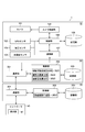
- FIG. 1 is a schematic diagram showing a configuration example of the information processing system 1 of the first embodiment
- FIG. 2 is a block diagram showing a configuration example of the information processing system 1.
- the information processing system 1 includes drone machines 10 and 20, an information processing device 30, and a controller 40.
- the drone machines 10 and 20 and the information processing device 30 are connected to each other so as to be able to communicate with each other via the network N.
- the network N may be the Internet, a mobile communication network, a local area network, or the like, or may be a network in which these plurality of types of networks are combined.
- the drone body 20 and the controller 40 are connected by wireless communication.
- the communication standard for connecting the second drone body 20 and the controller 40 is typically LTE (Long Term Evolution) communication, but the communication standard is not limited to this, and the type is not limited, for example, Wi-Fi.
- the drone body 10 includes a camera 101, a GPS sensor 102, a barometric pressure sensor 103, an acceleration sensor 104, a camera control unit 105, a control unit 106, a communication unit 107, and a storage unit 108. And have.
- the drone body 10 is an example of a "moving object" within the scope of claims.
- the camera 101 actually uses various members such as an image pickup device such as a CMOS (Complementary Metal Oxide Semiconductor) or a CCD (Charge Coupled Device) and a lens for controlling the image formation of a subject image on the image pickup device. It is a device that captures a space and generates an captured image. The camera 101 may capture a still image or may capture a moving image. The camera 101 is an example of the "imaging unit" in the claims.
- an image pickup device such as a CMOS (Complementary Metal Oxide Semiconductor) or a CCD (Charge Coupled Device)
- CMOS Complementary Metal Oxide Semiconductor
- CCD Charge Coupled Device
- the GPS sensor 102 receives a signal from GPS satellites and measures the current latitude and longitude of the drone aircraft 10 in real time.
- the GPS sensor 102 outputs sensor data relating to the latitude and longitude of the drone aircraft 10 calculated based on signals acquired from GPS satellites to the storage unit 108 and the movable area calculation unit 3021.
- the barometric pressure sensor 103 is a pressure sensor that measures the barometric pressure and measures the flight altitude (barometric altitude) of the drone aircraft 10 by converting it to altitude.
- the pressure sensor 103 detects the total pressure including the influence of the wind on the drone body 10 and the atmospheric pressure on the drone body 10, and determines the flight speed (airspeed) of the drone body 10 based on these differences. measure.
- the barometric pressure sensor 103 outputs the sensor data obtained by measuring the flight altitude and the flight speed of the drone body 10 to the storage unit 108 and the movable area calculation unit 3021.
- the barometric pressure sensor 103 may be, for example, a piezoresistive pressure sensor, and its type is not limited.
- the acceleration sensor 104 constantly detects the acceleration of the drone body 10.
- the acceleration sensor 104 detects various movements such as tilt and vibration of the drone body 10.
- the acceleration sensor 104 outputs the sensor data obtained by detecting the acceleration of the drone body 10 to the storage unit 108 and the movable area calculation unit 3021.
- the acceleration sensor 104 may be, for example, a piezoelectric type acceleration sensor, a servo type acceleration sensor, a strain type acceleration sensor, a semiconductor type acceleration sensor, or the like, and the type thereof does not matter.
- the camera control unit 105 generates a control signal for changing the shooting direction, posture, and shooting magnification of the camera 101 based on the control of the control unit 106, and outputs this signal to the camera 101.
- the camera control unit 105 controls the shooting direction and angle of view of the camera 101 via a pan head (not shown) incorporating a motor such as a 3-axis gimbal, and stores the control signal at this time in the storage unit 108 and the shooting range. Output to the calculation unit 3022.
- the control unit 106 controls the entire operation of the drone machine 10 or a part thereof according to the program stored in the storage unit 108.
- the communication unit 107 communicates with the information processing device 30 via the network N.
- the communication unit 107 functions as a communication interface for the drone body 10.
- the storage unit 108 stores the sensor data output from the GPS sensor 102, the pressure sensor 103, and the acceleration sensor 104, and the control signal output from the camera control unit 105.
- the drone machine 20 has a communication unit 201, a control unit 202, and a storage unit 203.
- the drone body 20 is an example of a "mobile body" within the scope of claims.
- the communication unit 201 communicates with the information processing device 30 via the network N.
- the communication unit 201 functions as a communication interface for the drone machine 20.
- the control unit 202 controls the entire operation of the drone machine 20 or a part thereof according to the program stored in the storage unit 203.
- the control unit 202 functionally has a movement route generation unit 2021.
- the movement route generation unit 2021 sets a waypoint, which is an intermediate target point of the drone aircraft 20, based on the photographing area of the drone aircraft 10, and generates a movement route of the drone aircraft 20 via the set waypoint.
- the information processing device 30 includes a communication unit 301, a control unit 302, and a storage unit 303.
- the information processing device 30 is typically a cloud server, but is not limited to this, and may be any other computer such as a PC.
- the communication unit 301 communicates with the drone aircraft 10 and 20 via the network N.
- the communication unit 301 functions as a communication interface of the information processing device 30.
- the control unit 302 controls the entire operation of the information processing device 30 or a part thereof according to the program stored in the storage unit 303.
- the control unit 302 functionally has a movable area calculation unit 3021, a shooting range calculation unit 3022, and a shooting area calculation unit 3023.
- the movable area calculation unit 3021 includes sensor data (latitude, longitude and altitude of the drone aircraft 10) acquired from the GPS sensor 102 and the pressure sensor 103, and the aircraft performance of the drone aircraft 10 (maximum speed, maximum climbing speed, maximum acceleration, etc.). Based on the maximum ascending acceleration and the maximum descending acceleration), the movable area in which the drone body 10 can move is calculated.
- the sensor data acquired from the GPS sensor 102 and the barometric pressure sensor 103 is an example of "state information of a moving object" in the claims
- the aircraft performance of the drone aircraft 10 is an example of "performance information of a moving object". ..
- the shooting range calculation unit 3022 includes a control signal (shooting direction and angle of view of the camera 101) acquired from the camera control unit 105, the body performance of the camera 101 (changeable range and changing speed of the shooting direction of the camera 101, and the camera 101).
- the possible shooting range of the camera 101 is calculated based on the changeable range and changing speed of the angle of view.
- the control signal from the camera control unit 105 is an example of "state information of the imaging unit" in the claims, and the airframe performance of the camera 101 is an example of "performance information of the imaging unit".
- the shooting area calculation unit 3023 is a movable area based on the movable area of the drone aircraft 10 calculated by the movable area calculation unit 3021 and the shooting range of the camera 101 calculated by the shooting range calculation unit 3022. At the point, the shootable area of the drone machine 10 is calculated by superimposing all the shootable ranges calculated from the angle of view and the shooting direction of the camera 101 at that time.
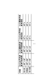
- the storage unit 303 stores data (FIG. 3) in which the model numbers of each of the plurality of drone aircraft and the aircraft performance are associated with each other.
- the storage unit 303 stores data (FIGS. 4 and 5) in which the model numbers of each of the plurality of drone aircraft and the aircraft performance of the camera 101 are associated with each other.
- FIG. 3 is an example of a data table in which the model number of the drone aircraft and the aircraft performance are associated with each other
- FIGS. 4 and 5 are an example of a data table in which the model number of the drone aircraft and the aircraft performance of the camera 101 are associated with each other. .. It should be noted that the specific numerical values shown in FIGS. 3 to 6, 10 and 13 are merely examples, and it goes without saying that the numerical values are not limited to these numerical values.
- the storage unit 303 periodically acquires the current states of the drone machine 10 and the camera 101 from the drone machine 10 and stores them. Specifically, the storage unit 303 contains information on the current latitude, longitude, altitude, and speed of the drone body 10, the current horizontal angle of the camera 101 (the angle formed by the optical axis of the camera 101 and the vertical plane), and the vertical. Information on the angle (the angle formed by the optical axis of the camera 101 and the horizontal direction), the horizontal angle of view, and the vertical angle of view is periodically acquired from the drone machine 10 and updated.
- FIG. 6 is an example of a data table showing the current state of the drone machine 10.
- the storage unit 303 of the present embodiment stores the current state of the drone machine 10 as a data table as shown in FIG. 6, for example, and periodically updates this data table.
- the storage unit 303 has a time interval (hereinafter, predetermined time t 1 ) from the acquisition of the aircraft state table, which will be described later, to setting a waypoint, and an update interval (hereinafter, predetermined time t 2 ) of the aircraft state table. And the local feature amount of each of the plurality of drone aircraft are memorized.
- the controller 40 is a control device for controlling the drone body 20, and has a display unit 41.
- the display unit 41 is, for example, a display device such as an LCD or an organic EL display.
- the display unit 41 displays an image taken by the camera 116 mounted on the drone body 20. As a result, the user can operate the drone machine 20 while watching the image displayed on the display unit 41.
- FIG. 7 is a block diagram showing a hardware configuration example of the drone bodies 10 and 20 and the information processing device 30.
- the drone machines 10 and 20 and the information processing device 30 may be realized by the information processing device 100.
- the information processing device 100 has a CPU (Central Processing unit) 110, a ROM (Read Only Memory) 111, and a RAM (Random Access Memory) 112.
- the control units 106, 202, 302 may be the CPU 111.
- the information processing device 100 has a configuration including a host bus 113, a bridge 114, an external bus 115, an interface 121, an input device 122, an output device 123, a storage device 124, a drive 125, a connection port 126, and a communication device 127. May be good.
- the information processing device 100 may have a configuration including a camera control unit 117, a camera 116, a GPS sensor 118, an acceleration sensor 119, and a barometric pressure sensor 120.
- the information processing device 100 replaces or is used with a processing circuit such as a DSP (Digital Signal Processor), an ASIC (Application Specific Integrated Circuit), an FPGA (Field-Programmable Gate Array), or a GPU (Graphics Processing Unit). May have.
- a processing circuit such as a DSP (Digital Signal Processor), an ASIC (Application Specific Integrated Circuit), an FPGA (Field-Programmable Gate Array), or a GPU (Graphics Processing Unit). May have.
- the CPU 110 functions as an arithmetic processing device and a control device, and controls all or a part of the operation of the information processing device 100 according to various programs recorded in the ROM 111, the RAM 112, the storage device 124, or the removable recording medium 50.
- the storage units 108, 203, and 303 may be the ROM 111, the RAM 112, the storage device 124, or the removable recording medium 50.
- the ROM 111 stores programs and calculation parameters used by the CPU 110.
- the RAM 112 primarily stores a program used in the execution of the CPU 110, parameters that are appropriately changed in the execution, and the like.
- the CPU 110, ROM 111, and RAM 112 are connected to each other by a host bus 113 composed of an internal bus such as a CPU bus. Further, the host bus 113 is connected to an external bus 115 such as a PCI (Peripheral Component Interconnect / Interface) bus via a bridge 114.
- a PCI Peripheral Component Interconnect / Interface
- the input device 122 is a device operated by a user, such as a touch panel, a button, a switch, and a lever.
- the input device 122 may be, for example, a remote control device using infrared rays or other radio waves, or an externally connected device 60 such as a mobile phone corresponding to the operation of the information processing device 100.
- the input device 122 includes an input control circuit that generates an input signal based on the information input by the user and outputs the input signal to the CPU 110. By operating the input device 122, the user inputs various data to the information processing device 100 and instructs the processing operation.
- the output device 123 is composed of a device capable of notifying the user of the acquired information using sensations such as sight, hearing, and touch.
- the output device 123 may be, for example, a display device such as an LCD (Liquid Crystal Display) or an organic EL (Electro-Luminescence) display, an audio output device such as a speaker or a headphone, or a vibrator.
- a display device such as an LCD (Liquid Crystal Display) or an organic EL (Electro-Luminescence) display
- an audio output device such as a speaker or a headphone, or a vibrator.
- the output device 123 outputs the result obtained by the processing of the information processing device 100 as a video such as text or an image, a voice such as voice or sound, or a vibration.
- the storage device 124 is a data storage device configured as an example of the storage unit of the information processing device 100.
- the storage device 124 is composed of, for example, a magnetic storage device such as an HDD (Hard Disk Drive), a semiconductor storage device, an optical storage device, an optical magnetic storage device, or the like.
- the storage device 124 stores, for example, a program executed by the CPU 110, various data, various data acquired from the outside, and the like.
- the drive 125 is a reader / writer for a removable recording medium 50 such as a magnetic disk, an optical disk, a magneto-optical disk, or a semiconductor memory, and is built in or externally attached to the information processing device 100.
- the drive 125 reads the information recorded in the removable recording medium 50 mounted on the drive 125 and outputs the information to the RAM 112. Further, the drive 125 writes a record on the removable recording medium 50 mounted on the drive 125.
- the connection port 126 is a port for connecting the device to the information processing device 100.
- the connection port 126 may be, for example, a USB (Universal Serial Bus) port, an IEEE1394 port, a SCSI (Small Computer System Interface) port, or the like. Further, the connection port 126 may be an RS-232C port, an optical audio terminal, an HDMI (registered trademark) (High-Definition Multimedia Interface) port, or the like.
- the communication device 127 is, for example, a communication interface composed of a communication device for connecting to the network N.
- the communication device 127 may be, for example, a communication card for LAN (Local Area Network), Bluetooth (registered trademark), Wi-Fi, WUSB (Wireless USB), or LTE. Further, the communication device 127 may be a router for optical communication, a router for ADSL (Asymmetric Digital Subscriber Line), a modem for various communications, or the like.
- the communication device 127 transmits and receives signals and the like to and from the Internet and other communication devices using a predetermined protocol such as TCP / IP.
- the network N connected to the communication device 127 is a network connected by radio, and may include, for example, the Internet, infrared communication, radio wave communication, short-range wireless communication, satellite communication, and the like.
- the communication units 107, 201, 301 may be the communication device 127.
- the camera control unit 117, camera 116, GPS sensor 118, acceleration sensor 119, and pressure sensor 120 correspond to the camera control unit 105, camera 101, GPS sensor 102, acceleration sensor 104, and pressure sensor 103, respectively.
- Each of the above components may be configured by using a general-purpose member, or may be composed of a member specialized in the function of each component. Such a configuration can be appropriately changed depending on the technical level at the time of implementation.
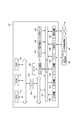
- FIG. 8 is a flowchart showing a typical operation flow of the information processing system 1. Hereinafter, the operation of the information processing system 1 will be described with reference to FIG. 8 as appropriate.
- Step S101 Calculate the movable area
- the camera 116 mounted on the drone body 20 images the drone body 10.
- the movable area calculation unit 3021 performs predetermined image processing on the captured image captured by the drone machine 10, and specifies the model name or model number of the drone machine 10. Specifically, the movable area calculation unit 3021 extracts the local feature amount of the 3D shape of the drone machine 10 from the captured image captured by the drone machine 10.
- Local features include, for example, SIFT (scale invariant features transform), SURF (speed-up robust features), RIFF (rotation invariant fast features), BREIF (binary robust independent elementary features), BRISK (binary robust invariant scalable key). It is a feature amount calculated by ORB (oriented FAST and rotated BRIEF) or CARD (compact and real-time descriptors).
- the movable area calculation unit 3021 determines the drone machine 10 by feature amount matching that compares the local feature amount of the 3D shape of the drone machine 10 with the local feature amount of each of the plurality of drone machines stored in advance in the storage unit 303. Detect and specify the model name or model number of the drone machine 10.
- the movable area calculation unit 3021 receives sensor data in which the latitude and longitude of the drone aircraft 10 are sensed by the GPS sensor 102, sensor data in which the altitude and current speed of the drone aircraft 10 are sensed by the pressure sensor 103, and the sensor data.
- Data hereinafter referred to as the aircraft state table
- the aircraft state table Data (hereinafter referred to as the aircraft state table) associated with the current shooting direction (horizontal angle, vertical angle) and the angle of view (horizontal angle of view, vertical angle of view) of the camera 101 is acquired from the drone aircraft 10 (hereinafter, the aircraft state table). (See FIG. 6).
- the movable area calculation unit 3021 refers to the data table (FIG. 3) stored in the storage unit 303, and thereby, the machine performance of the drone machine 10 associated with the model number or model name specified earlier ( The maximum speed, the maximum ascending speed, the maximum descending speed, the maximum acceleration, the maximum ascending acceleration, the maximum descending acceleration) and the time t 1 are read out from the storage unit 303.
- the movable area calculation unit 3021 accelerates at the maximum acceleration from the current position (latitude, longitude and altitude) of the drone aircraft 10 with the maximum speed as the upper limit from the current speed of the drone aircraft 10 from this current position.
- the maximum moving range E1 in the horizontal direction (XY plane direction) of the case is calculated.
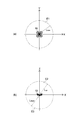
- FIG. 9a is a conceptual diagram showing the maximum moving range E1 of the drone body 10 in the horizontal direction.
- the maximum movement range E1 is calculated by, for example, the following equations (1) and (2), where the current speed, maximum acceleration, and maximum movement distance of the drone aircraft 10 are V 0 , a h , and L h , respectively.
- the X, Y, and Z axes in FIG. 9 are three-axis directions orthogonal to each other, and are also common in the following figures.
- the movable area calculation unit 3021 uses the current position (latitude, longitude, and altitude) of the drone aircraft 10 as a base point, and from this current position to the current speed of the drone aircraft 10 with the maximum ascending speed as the upper limit, at the maximum ascending acceleration.
- the maximum ascending range E2 in the vertical plane direction (XZ plane direction) when ascending is calculated.
- FIG. 9b is a conceptual diagram showing the maximum ascending range and the maximum descending range of the drone body 10 in the vertical plane direction.
- the maximum climb range E2 is calculated by, for example, the following equations (3) and (4), where the current speed, maximum climb acceleration, and maximum climb distance of the drone aircraft 10 are V 0 , a up , and L up , respectively.
- the movable area calculation unit 3021 uses the current position (latitude, longitude and altitude) of the drone aircraft 10 as a base point, and sets the maximum descent speed from the current speed of the drone aircraft 10 to the maximum descent speed from this current position.
- the maximum descent range E3 in the vertical plane direction when descending is calculated.
- the maximum descent range E3 is calculated by, for example, the following equations (5) and (6) when the current speed, the maximum descent acceleration, and the maximum descent distance of the drone aircraft 10 are V down , a down , and L down , respectively.
- the movable area calculation unit 3021 combines the calculated maximum moving range E1, maximum ascending range E2, and maximum descending range E3, calculates the maximum movable area E defined by these, and determines the predetermined time of the drone aircraft 10.
- the maximum movable area E that can be taken in t 1 is specified.
- the movable area calculation unit 2051 outputs the calculation result of calculating the maximum movable area E to the movement route generation unit 2021.
- the maximum movable area E is an example of the “movable area” in the claims.
- the maximum movable area E may be defined as a cylinder calculated by, for example, the following equation (7) when the maximum moving distance, the maximum ascending distance, and the maximum descending distance are L h , L up , and L down , respectively. ..
- the maximum movable region E may be defined as an elliptical sphere calculated by, for example, the following formula (8).
- Step S102 Calculate the shootable range
- the shooting range calculation unit 3022 refers to the aircraft performance (camera 101) of the camera 101 associated with the model number or model name specified in the previous step S101.
- the time t 2 is read from the storage unit 303.
- the shooting range calculation unit 3022 uses the current horizontal angle of the camera 101 acquired in the previous step S101 as a base point, and within the predetermined time t 2 of the camera 101 with the horizontal angle changeable range from the horizontal angle as the upper limit.
- the maximum horizontal angle range A1 that can be taken is calculated.
- the maximum angle range A1 is, for example, the following when the current horizontal angle, horizontal angle change speed, and horizontal angle changeable range of the camera 101 are ⁇ H , ⁇ Hs , and ⁇ H (min) to ⁇ H (max) , respectively.
- the shooting range calculation unit 3022 as a base point the current vertical angle of the camera 101, as an upper limit vertical angle variable range of the vertical angle, the maximum angular range in the vertical direction that can be taken within a predetermined time t 2 of the camera 101 Calculate A2.
- the maximum angle range A2 is, for example, the following when the current vertical angle, vertical angle changing speed, and vertical angle changeable range of the camera 101 are ⁇ V , ⁇ Vs , and ⁇ V (min) to ⁇ V (max) , respectively. It is calculated by the formula (10).
- the shooting range calculation unit 3022 as a base point of the current horizontal angle of the camera 101, a maximum of horizontal angle variable range of the horizontal angle, the maximum horizontal possible in a predetermined time t 2 of the camera 101 The angle of view ⁇ hav is calculated.
- the current horizontal angle of view, the horizontal angle of view change speed, and the horizontal angle of view changeable range of the camera 101 are set to ⁇ AH , ⁇ AHs , and ⁇ AH (min) to ⁇ AH (max) , respectively.
- ⁇ AH the horizontal angle of view change speed
- ⁇ AH the horizontal angle of view changeable range of the camera 101
- the shooting range calculation unit 3022 uses the current vertical angle of view of the camera 101 as a base point, and the maximum vertical angle that can be taken within a predetermined time t 2 of the camera 101 with the vertical angle of view changeable range as the upper limit.
- the angle of view ⁇ vav is calculated.
- the current vertical angle of view, the vertical angle of view change speed, and the vertical angle of view changeable range of the camera 101 are set to ⁇ VH , ⁇ VHs , and ⁇ VH (min) to ⁇ VH (max) , respectively.
- ⁇ VH , ⁇ VHs , and ⁇ VH (min) to ⁇ VH (max) respectively.
- it is calculated by the following formula (12).
- the shooting range calculation unit 2052 calculates the maximum shootable range R based on the maximum angle ranges A1 and A2, the maximum horizontal angle of view ⁇ hav, and the maximum vertical angle of view ⁇ vav , and the current shooting direction and image of the camera 101.
- the maximum possible shooting range R within a predetermined time t 2 is specified from the angle.
- the maximum photographable range R is an example of the "photographable range" of the claims.
- FIG. 10 is an example of a data table showing the update history of the aircraft state table, and is a diagram showing a process in which the maximum movable area E, the maximum photographable range R, the maximum photographable area D, and the waypoint P are generated over time. Is.
- the shooting range calculation unit 3022 of the present embodiment performs the previous step S102 every predetermined time t 2 when the predetermined time t 1 has not elapsed since the aircraft status table was acquired from the drone aircraft 10 (NO in step S103). Repeat to. Thus, body condition table stored in the storage unit 303 is updated every predetermined time t 2.
- the photographing range calculation unit 3022 between the drone aircraft 20 is to get the aircraft state table until a predetermined time t 1 has elapsed, the maximum photographable range R from drone aircraft 10 every time to get the aircraft status table calculate. That is, as shown in FIG. 10, the shooting range calculation unit 3022 has a maximum shooting range according to the shooting direction (horizontal angle, vertical angle) and angle of view (horizontal angle of view, vertical angle of view) of the camera 101 at that time. R is calculated every predetermined time t 2 . The shooting range calculation unit 3022 outputs the calculation result of calculating the maximum shootable range R every predetermined time t 2 to the shooting area calculation unit 3023.
- Step S104 Calculate the shootable area
- the photographing area calculation unit 3023 performs the maximum photographing calculated every predetermined time t 2 by the photographing range calculation unit 3022.
- range R calculates the maximum photographable region D by overlaying all, calculates the maximum photographable region D which can be taken at a predetermined time t 1 of the camera 101.
- the maximum photographable area D is an example of the “photographable area” in the claims.
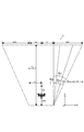
- FIG. 12 is a diagram schematically showing a cross section of the maximum photographable region D.
- the maximum movable area E is defined as a cylinder calculated by, for example, the equation (7)
- the photographing area calculation unit 3023 sets the vertical tilt angle of the drone body 10 and the height of the maximum imageable area D as ⁇ VP , respectively.
- the L V for example may be defined as a truncated cone, which is calculated by the following equation (13) to (15).
- the height Lv of the maximum photographable area D is such that the camera 101 of the drone body 10 cannot recognize (do not reflect) the drone body 20, and the lateral size of the image sensor of the camera 101 is set to Ds.
- the focal length of the camera 101 at the time of maximum zoom is F and the field of view size of the camera 101 is Fv, it is calculated by, for example, the following equation (16).
- the shooting area calculation unit 3023 outputs the calculation result of calculating the maximum shootable area D to the movement path generation unit 2021 and the controller 40.
- the display unit 41 of the controller 40 displays the maximum shootable area D of the drone body 10. At this time, the display unit 41 generates an overlay image in which the maximum shootable area D is virtually superimposed on the image captured by the camera 116, and displays this image. As a result, the user can confirm the maximum photographable area D of the drone machine 10 as visualized information.
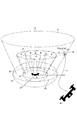
- FIG. 11 is a diagram showing a situation in which the drone aircraft 20 flies so as not to intersect the maximum photographable area D of the drone aircraft 10.
- the movement route generation unit 2021 sets the waypoint P (intermediate target point) so as not to be included in the virtual obstacle, with the maximum movable area E and the maximum photographable area D of the drone aircraft 10 as virtual obstacles.
- a movement path L via the waypoint P is generated.
- the movement route generation unit 2021 generates the movement route L according to a path search algorithm such as A * (A star) or D * (D star).
- the movement path generation unit 2021 is based on the coordinate position of each point of the point cloud data constituting the maximum movable area E and the body width L1 of the drone machine 20, and the coordinate position (x p) of the waypoint P. , Y p , z p ) is calculated, and a movement path L via this coordinate position (x p , y p , z p ) is generated.
- the movement path generation section 2021 for example, when the travel path L passes through the widthwise center of the drone aircraft 20, the coordinate position of any point P a group of data points constituting the outermost periphery of the maximum photographable region D (x a, y a, z a) the coordinate position (x p, y p, z p) such that the distance L2 between the is larger than the body width L1, a coordinate position (x p, y p, z p ) Is set.
- the body width L1 is, for example, the distance from the center of the drone body 20 in the width direction to the end in the width direction.
- the information processing system 1 of the present embodiment repeatedly executes a series of steps up to the previous step S101 ⁇ step S105 every predetermined time t 1.
- the maximum photographable area D of the drone body 10 according to the situation at that time is generated every predetermined time t 1 , and the waypoint P is intermittently set every predetermined time t 1 .
- the information processing device 30 generates a maximum shootable range R every predetermined time t 2 within a range in which the drone machine 10 can move to the maximum within a predetermined time t 1 , and the drone machine 10 is derived from these maximum shootable ranges R. There is calculated the maximum up get focus range (maximum photographable region D) at a predetermined time t 1. Then, the drone aircraft 10 generates a movement path L that does not intersect the shooting range.
- drone aircraft 10 is within the unexpected shooting range of the camera 101 even took action maximum possible imaging region D of the spikes and lowered like a predetermined time t 1.
- the information processing device 30 executes arithmetic processing for calculating the maximum movable area E and the maximum photographable area D of the drone machine 10. That is, the information processing device 30 plays a part in the arithmetic processing to be executed by the drone machine 20 in order to prevent the drone machine 20 from being reflected in the shooting range of the drone machine 10. As a result, the calculation load of the drone machine 20 can be significantly reduced. Further, since it is not necessary to increase the arithmetic processing capacity of the drone machine 20, the design cost of the drone machine 20 can be suppressed.
- FIG. 13 is a flowchart showing a typical operation flow of the information processing system 1 of the second embodiment.
- the information processing system 1 can also execute the following steps in addition to the operations described in the first embodiment.
- the operation of the information processing system 1 of the second embodiment will be described with reference to FIG. 12 as appropriate.
- the configuration is similarly coded, and the description thereof will be omitted.
- the drone machine 10 predicts the shootable area that the drone machine 10 can take within a specific time from the past history of the state of the drone machine 10, and the drone machine 20 avoids the predicted shootable area. Therefore, it is different from the first embodiment.
- FIG. 14 is an example of an airframe state table and a data table showing the update history of the change range of the actual shooting direction and angle of view of the camera 101.
- the storage unit 303 of the second embodiment stores, for example, the update history of the data associated with the aircraft state table, the moving area, the horizontal angle change range, the vertical angle change range, the horizontal angle change range, and the vertical angle change range. It is stored as a data table as shown in FIG. 14, and this data table is updated every predetermined time t 2 .
- moving region shown in FIG. 14, a range of movement drone aircraft 10 has actually moved to the predetermined time t 1 is the same in the following description.
- the "horizontal angle change range” is the actual change range of the horizontal angle within the predetermined time t 1 of the camera 101
- the “vertical angle change range” is the actual change of the vertical angle within the predetermined time t 1 of the camera 101. The range.
- horizontal angle change range is the actual range of change in horizontal angle within a predetermined time t 1 of the camera 101
- vertical angle change range vertical angle of the predetermined time t 1 of the camera 101
- the definitions of the above-mentioned “horizontal angle change range”, “vertical angle change range”, “horizontal angle of view change range”, and “vertical angle of view change range” are the same in the following description.
- control unit 302 acquires an aircraft state table showing the current state of the drone aircraft 10 from the drone aircraft 10 (FIG. 14a).
- control unit 302 refers to the data table (FIG. 13) stored in the storage unit 303, and from the update history of the data table (FIG. 13), the current latitude, longitude, and altitude of the drone aircraft 10 , Speed and history information most similar to the current horizontal, vertical, horizontal and vertical angles of view of the camera 101 (FIG. 14b).
- control unit 302 selects a movement area, a horizontal angle change range, a vertical angle change range, a horizontal angle of view change range, and a vertical angle of view change range associated with the selected history information (FIG. 14c).
- Step S202 Predict the shooting range
- Shooting range calculation unit 3022 the center of the current horizontal angle of the camera 101, as an upper limit the horizontal angle variable range of the horizontal angle, predicts the horizontal angle range A1' within a predetermined time of the camera 101 t 2 ..
- the angle range A1' is defined as follows, for example, when the current horizontal angle, horizontal angle change range, and horizontal angle changeable range of the camera 101 are ⁇ H , ⁇ Ha , and ⁇ H (min) to ⁇ H (max) , respectively. Calculated by equation (16)
- the shooting range calculation unit 3022 the center of the current vertical angle of the camera 101, as an upper limit vertical angle variable range of the vertical angle, a vertical angle range A2' within a predetermined time of the camera 101 t 2 Predict.
- the angle range A2' is described below, for example, when the current vertical angle, vertical angle change range, and vertical angle changeable range of the camera 101 are ⁇ V , ⁇ Va , and ⁇ V (min) to ⁇ V (max) , respectively. Equation (1 Calculated according to 7).
- the shooting range calculation unit 3022 centers on the current horizontal angle of view of the camera 101, and the horizontal angle of view ⁇ hav within a predetermined time t 2 of the camera 101 with the horizontal angle of view changeable range as the upper limit. Predict.
- the current horizontal angle of view, the horizontal angle of view change range, and the horizontal angle of view changeable range of the camera 101 are set to ⁇ AH , ⁇ AHa , and ⁇ AH (min) to ⁇ AH (max) , respectively.
- ⁇ AH the horizontal angle of view
- ⁇ AHa the horizontal angle of view change range
- ⁇ AH (min) the horizontal angle of view changeable range of the camera 101
- the shooting range calculation unit 3022 centers on the current vertical angle of view of the camera 101, with the vertical angle of view changeable range as the upper limit, and the vertical angle of view ⁇ within the predetermined time t 2 of the camera 101. Calculate vav '.
- the current vertical angle of view, the vertical angle of view change range, and the vertical angle of view changeable range of the camera 101 are set to ⁇ VH , ⁇ VHa , and ⁇ VH (min) to ⁇ VH (max) , respectively.
- ⁇ VH , ⁇ VHa , and ⁇ VH (min) to ⁇ VH (max) respectively.
- it is calculated by the following formula (19).
- the shooting range calculation unit 3022 calculates the shootable range R'based on the angle ranges A1 ', A2 ', the horizontal angle of view ⁇ hav ', and the vertical angle of view ⁇ vav ', and the current shooting direction of the camera 101 and The photographable range R'within a predetermined time t 2 is predicted from the angle of view.
- Step S203 Has the predetermined time passed?)
- the shooting range calculation unit 3022 repeats the previous step S202 every predetermined time t 2 when the predetermined time t 1 has not elapsed since the drone aircraft 10 acquired the aircraft state table (NO in step S203).
- the data table stored in the storage unit 303 (FIG. 14) is updated every predetermined time t 2.
- the photographing range calculation unit 3022 between the drone aircraft 20 is to get the aircraft state table until a predetermined time t 1 has elapsed, the photographable range R'from drone aircraft 10 every time to get the aircraft status table Predict. That is, the shooting range calculation unit 3022 sets the shooting range R'according to the shooting direction (horizontal angle, vertical angle) and angle of view (horizontal angle of view, vertical angle of view) of the camera 101 at a predetermined time every t 2. Calculate to. The shooting range calculation unit 3022 outputs the calculation result of calculating the shootable range R'for every predetermined time t 2 to the shooting area calculation unit 3023.
- Step S204 Predicting the shooting area
- the photographing area calculation unit 3023 can perform photographing calculated every predetermined time t 2 by the photographing range calculation unit 3022.
- the photographable area D' is predicted by overlapping all the ranges R'.
- Imaging area calculating unit 3023, a photographable region D'within a predetermined time t 1 of the camera 101 is calculated in the same manner as in the first embodiment, and outputs the calculated result of calculating the recordable region D'to the controller 40 ..
- the display unit 41 of the controller 40 displays the photographable area D'of the drone aircraft 10. At this time, the display unit 41 generates an overlay image in which the shootable area D'is virtually superimposed on the image captured by the camera 119, and displays this image. As a result, the user can confirm the photographable area D'of the drone aircraft 10 as visualized information.
- FIG. 15 is a diagram showing a situation in which the drone aircraft 20 flies while avoiding the photographable area D'of the drone aircraft 10.
- the shooting area calculation unit 3023 refers to the aircraft performance of the drone aircraft 20 stored in the storage unit 303 (for example, maximum speed, maximum ascending speed, maximum descending speed, maximum acceleration, maximum ascending acceleration, maximum descending acceleration, etc.). , It is determined whether to generate the movement path to avoid the maximum photographable area D or the photographable area D'.
- the shooting area calculation unit 3023 determines from the aircraft performance of the drone machine 20 whether or not the waypoint P not included in the maximum shootable area D can be set, and if it is possible to set the waypoint P, the setting is possible. Similar to the first embodiment described above, the movement path generation unit 2021 sets the waypoint P not included in the maximum photographable area D, and the drone aircraft 20 generates the movement path L via the waypoint P.
- the shooting area calculation unit 3023 determines that the waypoint P not included in the maximum shootable area D cannot be set from the aircraft performance of the drone machine 20, the calculation result of calculating the shootable area D'is calculated. Output to the movement route generation unit 2021.
- Movement path generation section 2021 a recordable region D'the previous virtual obstacle movement area selected at step S201, the coordinate position of the waypoint P'work around this virtual obstacle (x p ', y p ⁇ , z p ′) is calculated, and a movement path L ′ via this coordinate position (x p ′, y p ′, z p ′) is generated.
- the information processing system 1 of the second embodiment repeatedly executes a series of steps up to the previous step S201 ⁇ step S205 every predetermined time t 1.
- the photographable area D'of the drone body 10 according to the situation at that time is predicted every predetermined time t 1 , and the waypoint P'is intermittently set every predetermined time t 1 .
- the shooting direction (horizontal angle change range, vertical angle change range) and image angle (horizontal angle change range, vertical angle change range) of the camera 101 are actually changed. From the history of the change range, select the change range associated with the history information most similar to the current shooting direction (horizontal angle, vertical angle) and image angle (horizontal angle, vertical angle) of the camera 101. The shooting area D'of the camera 101 is calculated based on the selected change range. Then, the drone body 20 generates a movement path L'that does not intersect with the photographable area D'.
- drone aircraft 20 is visible on captured imaging range of the drone aircraft 10 at a predetermined time t 1.
- the information processing device 30 of the second embodiment determines whether to generate a movement path to avoid the maximum shootable area D or the shootable area D'based on the machine performance of the drone machine 20.
- the information processing apparatus 30 generates a movement path L'that avoids the imageable area D'when it is determined that the movement path that avoids the maximum photographable area D cannot be generated.
- FIG. 16 is a block diagram showing a configuration example of the information processing system 3 according to the third embodiment of the present technology.
- the same configurations as in the first embodiment will be designated by the same reference numerals, and the description thereof will be omitted or simplified.
- the drone machine 20 when the arithmetic processing capacity of the drone machine 20 itself is improved, or when the drone machine 20 cannot communicate with the information processing device 30, the drone machine 20 can take the maximum imageable area D of the drone machine 10. Is calculated, and the process of generating its own movement path that does not intersect with the maximum photographable area D is consistently executed, which is different from the first embodiment.
- the control unit 202 of the drone body 20 of the third embodiment functionally functions as a movement path generation unit 2021, a movable area calculation unit 3021, a shooting range calculation unit 3022, and a shooting area calculation unit 3023.
- a movement path generation unit 2021 As shown in FIG. 16, the control unit 202 of the drone body 20 of the third embodiment functionally functions as a movement path generation unit 2021, a movable area calculation unit 3021, a shooting range calculation unit 3022, and a shooting area calculation unit 3023.
- the information processing system 3 of the third embodiment executes an operation according to the flowchart shown in FIG.
- the information processing system 3 is other than the point that the drone machine 20 calculates the maximum shootable area D of the drone machine 10 and consistently executes the process of generating its own movement path that does not intersect with the maximum shootable area D. Operates in the same manner as in the first embodiment, and thus the description thereof will be omitted.
- the maximum shootable range R is calculated based on the current shooting direction and angle of view of the drone machine 10 and the machine performance of the drone machine 10, but the present invention is not limited to this.
- the information processing device 30 has a maximum shooting range R based on the stored upper limit value of the machine performance of the drone 10.
- the maximum photographable area D may be calculated to generate a movement path that does not intersect with the maximum imageable area D.
- an overlay image in which the maximum shootable area D (shootable area D') of the drone machine 10 is virtually superimposed on the image shot by the camera 116 is displayed on the display unit 41.
- information that calls attention to the user may be displayed on the display unit 41 in place of or together with the overlay image.
- the model number of the drone machine 10 is specified by image processing the captured image captured by the drone machine 10, but the model number is not limited to this.
- the movable area calculation unit 3021 acquires information on the model number or model name of the drone machine 10 together with the machine state table from the drone machine 10, and reads out the machine performance of the drone machine 10 and the camera 101 linked to these from the storage unit 303. You may use it.
- the maximum movable region E is calculated by using all of the maximum speed, the maximum ascending speed, the maximum descending speed, the maximum acceleration, the maximum ascending acceleration, and the maximum descending acceleration of the drone body 10. Not limited to this, at least one of the maximum speed, the maximum ascending speed, the maximum descending speed, the maximum acceleration, the maximum ascending acceleration, or the maximum descending acceleration may be used for calculating the maximum movable region E.
- an information processing device for example, an information processing device, a system, an information processing method executed by the information processing device or the system, a program for operating the information processing device, and a program as described above are recorded. It may include non-temporary tangible media.
- the description is made on the premise that the moving body is a flying body, but the description is not limited to this.
- the present technology may be applied to a moving body other than a flying body (for example, a robot), and its use is not particularly limited.
- the airframe may include an aircraft, an unmanned aerial vehicle, an unmanned helicopter, or the like.
- An acquisition unit that acquires the state information of the imaging unit of a moving object, It is provided with a control unit that calculates the imageable area of the imaging unit based on the state information.
- An information processing device that transmits information about the photographable area to a mobile body.
- the acquisition unit acquires the state information and the performance information of the moving object, and obtains the information.
- the control unit is an information processing device that calculates the imageable area based on the acquired state information and performance information of a moving object and the state information of the imaging unit.
- the control unit The movable area of the moving object is calculated based on the acquired state information and performance information of the moving object.
- An information processing device that calculates the photographable area based on the calculated movable area.
- the state information of the moving object includes information about the current position of the moving object.
- the performance information of the moving object includes information on the maximum speed, the maximum ascending speed, the maximum descending speed, the maximum acceleration, the maximum ascending acceleration and the maximum descending acceleration of the moving object.
- the control unit can move the moving object based on at least one of the maximum speed, the maximum ascending speed, the maximum descending speed, the maximum acceleration, the maximum ascending acceleration or the maximum descending acceleration, and the current position.
- An information processing device that calculates the area.
- the information processing device that calculates the area.
- the information processing device according to any one of (1) to (4) above.
- the acquisition unit acquires the performance information of the imaging unit and obtains the performance information.
- the control unit is an information processing device that calculates the imageable range of the imaging unit based on the state information and performance information of the imaging unit.
- the state information of the imaging unit includes information regarding the shooting direction and angle of view of the imaging unit.
- the performance information of the imaging unit includes information on the changeable range and changing speed of the shooting direction of the imaging unit and the changeable range and changing speed of the angle of view of the imaging unit.
- the control unit is an information processing device that calculates the shooting range based on the shooting direction and angle of view, the changeable range and change speed, and the view angle changeable range and angle of view change speed. (7) The information processing device according to (5) or (6) above.
- the control unit The above shooting range is calculated every predetermined time, An information processing device that calculates the photographable area based on the photographable range calculated for each predetermined time.
- the information processing device is an information processing device that is a server.
- An acquisition unit that acquires information about the imageable area of the image pickup unit, which is calculated based on the state information of the image pickup unit of the moving object.
- the moving body including a control unit that generates a moving path of the moving body that does not intersect with the photographable area.
- the above-mentioned moving body is a moving body which is a flying body.
- An acquisition unit that acquires the state information of the imaging unit of a moving object,
- the moving body including a control unit that calculates a photographing area of the imaging unit based on the state information and generates a moving path of the moving body that does not intersect with the photographing area.
- the above-mentioned moving body is a moving body which is a flying body.
- An information processing device that acquires the state information of the imaging unit of a moving object and calculates the imageable area of the imaging unit based on the state information.
- An information processing system including the moving body that acquires information about the photographable area from the information processing apparatus and generates a moving path of the moving body that does not intersect the photographable area.
- the information processing device Acquires the state information of the imaging unit of a moving object, Based on the above state information, the imageable area of the imaging unit is calculated. An information processing method for transmitting information about the photographable area to a moving body.
- Drone aircraft ⁇ ⁇ ⁇ 10,20 Information processing device 30,100
- Control unit 106, 202, 302 Communication unit (acquisition unit) ... 107, 201, 301
- R' Maximum shooting range R Movable area ...
- D' Maximum shootable area D Movement route: L, L'
Landscapes
- Engineering & Computer Science (AREA)
- Radar, Positioning & Navigation (AREA)
- Remote Sensing (AREA)
- Physics & Mathematics (AREA)
- General Physics & Mathematics (AREA)
- Aviation & Aerospace Engineering (AREA)
- Automation & Control Theory (AREA)
- Multimedia (AREA)
- Signal Processing (AREA)
- Health & Medical Sciences (AREA)
- Biomedical Technology (AREA)
- General Health & Medical Sciences (AREA)
- Studio Devices (AREA)
- Control Of Position, Course, Altitude, Or Attitude Of Moving Bodies (AREA)
Priority Applications (2)
| Application Number | Priority Date | Filing Date | Title |
|---|---|---|---|
| JP2021537611A JPWO2021024627A1 (https=) | 2019-08-08 | 2020-06-22 | |
| US17/630,928 US12055396B2 (en) | 2019-08-08 | 2020-06-22 | Information processing apparatus, moving body, information processing system, information processing method, and program |
Applications Claiming Priority (2)
| Application Number | Priority Date | Filing Date | Title |
|---|---|---|---|
| JP2019146147 | 2019-08-08 | ||
| JP2019-146147 | 2019-08-08 |
Publications (1)
| Publication Number | Publication Date |
|---|---|
| WO2021024627A1 true WO2021024627A1 (ja) | 2021-02-11 |
Family
ID=74502902
Family Applications (1)
| Application Number | Title | Priority Date | Filing Date |
|---|---|---|---|
| PCT/JP2020/024421 Ceased WO2021024627A1 (ja) | 2019-08-08 | 2020-06-22 | 情報処理装置、移動体、情報処理システム、情報処理方法及びプログラム |
Country Status (3)
| Country | Link |
|---|---|
| US (1) | US12055396B2 (https=) |
| JP (1) | JPWO2021024627A1 (https=) |
| WO (1) | WO2021024627A1 (https=) |
Cited By (1)
| Publication number | Priority date | Publication date | Assignee | Title |
|---|---|---|---|---|
| JP7692544B1 (ja) * | 2024-04-25 | 2025-06-13 | 三菱電機株式会社 | 飛行経路生成装置、飛行経路生成方法及び飛行経路生成プログラム |
Families Citing this family (1)
| Publication number | Priority date | Publication date | Assignee | Title |
|---|---|---|---|---|
| US11967035B1 (en) | 2023-10-20 | 2024-04-23 | Anarky Labs Oy | Visualizing area covered by drone camera |
Citations (4)
| Publication number | Priority date | Publication date | Assignee | Title |
|---|---|---|---|---|
| JP2018173960A (ja) * | 2017-03-31 | 2018-11-08 | キヤノンマーケティングジャパン株式会社 | 情報処理システム、及びその制御方法、プログラム |
| WO2019039099A1 (ja) * | 2017-08-23 | 2019-02-28 | キヤノン株式会社 | 制御装置、制御システム、制御方法、プログラム、及び記憶媒体 |
| JP2019514236A (ja) * | 2016-02-03 | 2019-05-30 | ソニー株式会社 | 複数カメラネットワークを利用して静止シーン及び/又は移動シーンを取り込むためのシステム及び方法 |
| WO2019244626A1 (ja) * | 2018-06-18 | 2019-12-26 | ソニー株式会社 | 移動体及び制御方法 |
Family Cites Families (8)
| Publication number | Priority date | Publication date | Assignee | Title |
|---|---|---|---|---|
| JP5149337B2 (ja) * | 2010-06-11 | 2013-02-20 | 株式会社バンダイナムコゲームス | プログラム、情報記憶媒体及び画像生成システム |
| US9810789B2 (en) * | 2012-12-19 | 2017-11-07 | Elwha Llc | Unoccupied flying vehicle (UFV) location assurance |
| US9646402B2 (en) * | 2015-06-19 | 2017-05-09 | International Business Machines Corporation | Geographic space management |
| WO2017201697A1 (en) * | 2016-05-25 | 2017-11-30 | SZ DJI Technology Co., Ltd. | Techniques for image recognition-based aerial vehicle navigation |
| JP6103672B1 (ja) | 2016-07-20 | 2017-03-29 | エスゼット ディージェイアイ テクノロジー カンパニー リミテッドSz Dji Technology Co.,Ltd | 制御装置、撮像装置、移動体、制御方法、及びプログラム |
| CN109716255A (zh) * | 2016-09-18 | 2019-05-03 | 深圳市大疆创新科技有限公司 | 用于操作可移动物体以规避障碍物的方法和系统 |
| CN109891351B (zh) * | 2016-11-15 | 2022-05-06 | 深圳市大疆创新科技有限公司 | 基于图像的对象检测和对应的移动调整操纵的方法和系统 |
| US11074811B2 (en) * | 2018-08-21 | 2021-07-27 | Here Global B.V. | Method and apparatus for using drones for road and traffic monitoring |
-
2020
- 2020-06-22 JP JP2021537611A patent/JPWO2021024627A1/ja active Pending
- 2020-06-22 WO PCT/JP2020/024421 patent/WO2021024627A1/ja not_active Ceased
- 2020-06-22 US US17/630,928 patent/US12055396B2/en active Active
Patent Citations (4)
| Publication number | Priority date | Publication date | Assignee | Title |
|---|---|---|---|---|
| JP2019514236A (ja) * | 2016-02-03 | 2019-05-30 | ソニー株式会社 | 複数カメラネットワークを利用して静止シーン及び/又は移動シーンを取り込むためのシステム及び方法 |
| JP2018173960A (ja) * | 2017-03-31 | 2018-11-08 | キヤノンマーケティングジャパン株式会社 | 情報処理システム、及びその制御方法、プログラム |
| WO2019039099A1 (ja) * | 2017-08-23 | 2019-02-28 | キヤノン株式会社 | 制御装置、制御システム、制御方法、プログラム、及び記憶媒体 |
| WO2019244626A1 (ja) * | 2018-06-18 | 2019-12-26 | ソニー株式会社 | 移動体及び制御方法 |
Non-Patent Citations (1)
| Title |
|---|
| TEMMA, RYOTARO, TAKASHIMA, KAZUKI, SUEDA, KOH, FUJITA, KAZUYUKI, KITAMURA, YOSHIFUMI: "Enhancing drone interface using spatially coupled two perspectives", PROCEEDINGS OF INTERACTION 2019, 4.5 AIRFRAME PERFORMANCE DESIGN, 6 March 2019 (2019-03-06), pages 102 - 111, XP055791628, Retrieved from the Internet <URL:http://www.interaction-ipsj.org/proceedings/2019/data/pdf/INT19012.pdf> * |
Cited By (2)
| Publication number | Priority date | Publication date | Assignee | Title |
|---|---|---|---|---|
| JP7692544B1 (ja) * | 2024-04-25 | 2025-06-13 | 三菱電機株式会社 | 飛行経路生成装置、飛行経路生成方法及び飛行経路生成プログラム |
| WO2025224917A1 (ja) * | 2024-04-25 | 2025-10-30 | 三菱電機株式会社 | 飛行経路生成装置、飛行経路生成方法及び飛行経路生成プログラム |
Also Published As
| Publication number | Publication date |
|---|---|
| US12055396B2 (en) | 2024-08-06 |
| JPWO2021024627A1 (https=) | 2021-02-11 |
| US20220205791A1 (en) | 2022-06-30 |
Similar Documents
| Publication | Publication Date | Title |
|---|---|---|
| CN108602561B (zh) | 用于利用多摄像机网络捕捉静态场景和/或运动场景的系统和方法 | |
| US10217021B2 (en) | Method for determining the position of a portable device | |
| CN112567201A (zh) | 距离测量方法以及设备 | |
| US20170078587A1 (en) | System and method for supporting photography with different effects | |
| US20200045239A1 (en) | Control device of movable type imaging device, control method of movable type imaging device, and program | |
| CN110785993A (zh) | 拍摄设备的控制方法、装置、设备及存储介质 | |
| EP2998934B1 (en) | Image processing device, image processing method, and program | |
| WO2022036500A1 (zh) | 无人飞行器的飞行辅助方法、设备、芯片、系统及介质 | |
| CN107256027A (zh) | 用于无人机的头盔及其控制方法 | |
| CN108702442A (zh) | 用于时刻捕获的系统和方法 | |
| WO2021024627A1 (ja) | 情報処理装置、移動体、情報処理システム、情報処理方法及びプログラム | |
| US20220262265A1 (en) | Information processing apparatus, information processing method, and program | |
| KR20200020295A (ko) | 로봇과 인터랙션하는 증강현실 서비스 제공 장치 및 방법 | |
| WO2020019113A1 (zh) | 移动机器人的控制方法、装置及移动机器人系统 | |
| JP7677147B2 (ja) | 移動体、情報処理装置、情報処理方法及びプログラム | |
| TW202126023A (zh) | 影像擷取方法及影像擷取設備 | |
| JP2021103410A (ja) | 移動体及び撮像システム | |
| JP7452543B2 (ja) | 情報処理装置、情報処理方法、プログラム及び情報処理システム | |
| CN111684784B (zh) | 图像处理方法和装置 | |
| JP2021086268A (ja) | 移動体、情報処理装置、及び撮像システム | |
| US11703856B2 (en) | Moving body, steering system, control method, and program | |
| CN110192161B (zh) | 使用射线投射映射来操作可移动平台的方法和系统 | |
| WO2025211022A1 (ja) | 情報処理方法、情報処理装置、及びプログラム | |
| JP2025035059A (ja) | 画像処理システム、移動体、画像処理方法、及びコンピュータプログラム | |
| JP2023083072A (ja) | 方法、システムおよびプログラム |
Legal Events
| Date | Code | Title | Description |
|---|---|---|---|
| 121 | Ep: the epo has been informed by wipo that ep was designated in this application |
Ref document number: 20850673 Country of ref document: EP Kind code of ref document: A1 |
|
| ENP | Entry into the national phase |
Ref document number: 2021537611 Country of ref document: JP Kind code of ref document: A |
|
| NENP | Non-entry into the national phase |
Ref country code: DE |
|
| 122 | Ep: pct application non-entry in european phase |
Ref document number: 20850673 Country of ref document: EP Kind code of ref document: A1 |