WO2021024336A1 - 位相アンラップ装置及び位相アンラップ方法 - Google Patents
位相アンラップ装置及び位相アンラップ方法 Download PDFInfo
- Publication number
- WO2021024336A1 WO2021024336A1 PCT/JP2019/030637 JP2019030637W WO2021024336A1 WO 2021024336 A1 WO2021024336 A1 WO 2021024336A1 JP 2019030637 W JP2019030637 W JP 2019030637W WO 2021024336 A1 WO2021024336 A1 WO 2021024336A1
- Authority
- WO
- WIPO (PCT)
- Prior art keywords
- phase
- unwrap
- coordinates
- discontinuity
- weight
- Prior art date
- Legal status (The legal status is an assumption and is not a legal conclusion. Google has not performed a legal analysis and makes no representation as to the accuracy of the status listed.)
- Ceased
Links
Images



Classifications
-
- G—PHYSICS
- G01—MEASURING; TESTING
- G01S—RADIO DIRECTION-FINDING; RADIO NAVIGATION; DETERMINING DISTANCE OR VELOCITY BY USE OF RADIO WAVES; LOCATING OR PRESENCE-DETECTING BY USE OF THE REFLECTION OR RERADIATION OF RADIO WAVES; ANALOGOUS ARRANGEMENTS USING OTHER WAVES
- G01S13/00—Systems using the reflection or reradiation of radio waves, e.g. radar systems; Analogous systems using reflection or reradiation of waves whose nature or wavelength is irrelevant or unspecified
- G01S13/88—Radar or analogous systems specially adapted for specific applications
- G01S13/89—Radar or analogous systems specially adapted for specific applications for mapping or imaging
- G01S13/90—Radar or analogous systems specially adapted for specific applications for mapping or imaging using synthetic aperture techniques, e.g. synthetic aperture radar [SAR] techniques
-
- G—PHYSICS
- G01—MEASURING; TESTING
- G01B—MEASURING LENGTH, THICKNESS OR SIMILAR LINEAR DIMENSIONS; MEASURING ANGLES; MEASURING AREAS; MEASURING IRREGULARITIES OF SURFACES OR CONTOURS
- G01B9/00—Measuring instruments characterised by the use of optical techniques
- G01B9/02—Interferometers
- G01B9/02055—Reduction or prevention of errors; Testing; Calibration
- G01B9/02075—Reduction or prevention of errors; Testing; Calibration of particular errors
-
- G—PHYSICS
- G06—COMPUTING OR CALCULATING; COUNTING
- G06T—IMAGE DATA PROCESSING OR GENERATION, IN GENERAL
- G06T1/00—General purpose image data processing
- G06T1/0007—Image acquisition
Definitions
- the present invention relates to a phase unwrapping device and a phase unwrapping method for returning a phase folded in the range of [ ⁇ , ⁇ ] to an absolute phase value.
- Synthetic Aperture Radar (SAR) technology is a technology that transmits and receives electromagnetic waves while flying objects such as artificial satellites and aircraft move, and obtains observation images equivalent to antennas with large apertures.
- Synthetic aperture radar is used, for example, to process reflected waves from the ground surface and analyze altitude and surface displacement.
- the analysis device takes a time-series SAR image (SAR data) obtained by the synthetic aperture radar as an input, and analyzes the input SAR image in a time-series manner.
- Interference SAR analysis is an effective method for analyzing altitude and surface displacement.
- the phase difference of the radio wave signals constituting a plurality of (for example, two) SAR images taken at different times is calculated. Then, from the phase difference, the change in the distance between the flying object and the ground that occurs during the shooting period is detected.
- phase unwrap is performed in which the phase is returned to an absolute phase value, that is, a phase value that is not folded and changes with a linear function with respect to the distance between the projectile and the ground.
- phase unwrap there is a method of integrating the phase difference between adjacent pixels in an interference SAR image (phase difference image). In reality, the phase difference between adjacent pixels is sequentially added along the integral path.
- phase unwrap is likely to be executed correctly, but the integral path should pass through the region where the phase difference between adjacent pixels is large (for example, larger than ⁇ ). In this case, accurate phase unwrapping may not be possible.
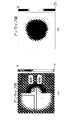
- FIG. 8 is an explanatory diagram showing an example of a phase difference image.
- FIG. 8A shows a phase difference image before the phase unwrap is executed.
- the path 1 is an integral path that does not avoid a region having a large phase difference.
- the path 2 is an integral path that avoids a region having a large phase difference.
- FIG. 8B exemplifies a phase difference image after the phase unwrap is executed for the path 2.
- FIG. 9 is an explanatory diagram for explaining a method of detecting a boundary.
- the phase differences of the four adjacent pixels are sequentially integrated (added).
- the part where the integrated value (added value) does not become 0 is regarded as the end of the region where the phase difference is large.
- the region where the integral value is 2 ⁇ and the region where the integral value is -2 ⁇ are the ends.
- the shortest path connecting the two ends is the boundary.
- Non-Patent Document 1 also describes a phase unwrap method.
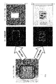
- FIG. 10 (A) when an object such as a building whose phase changes significantly is photographed (see FIG. 10 (A)), a phase discontinuity region occurs.
- the discontinuous boundary is correct due to the discontinuous region of the phase existing between the ends. It may not be determined (see FIG. 10B).
- the U-shaped portion indicates the boundary (discontinuous boundary) between the region where the phase difference is large and the region where the phase difference is not large.
- a group of white curves shows a portion determined to be a discontinuous boundary by a method in which the shortest path connecting both ends is a discontinuous boundary. If the discontinuous boundary is not determined correctly, an unwrap error occurs (see FIG. 10C).
- FIG. 10C it is illustrated that the phase folded in the range of [ ⁇ , ⁇ ] is extended to the range of [0,12 ⁇ ] by the phase unwrap.
- the lower figure of FIG. 10C illustrates that the phase folded in the range of [ ⁇ , ⁇ ] was extended only to the range of [0,2 ⁇ ] due to the phase unwrap. .. That is, it is shown that an unwrap error has occurred.
- An object of the present invention is to provide a phase unwrapping device and a phase unwrapping method capable of reducing the occurrence of unwrapping errors.
- the phase unwrap device is generated from two SAR images from a coordinate conversion means for converting the coordinates of a map having height information into the coordinates of a SAR image and a map in which the coordinates are converted into the coordinates of a SAR image.
- a weight calculation means for determining a portion of a phase difference image in which a phase discontinuity can occur and giving a weight to the portion determined to have a phase discontinuity, and a phase unwrap of the phase difference image using the weight. Includes phase unwrap means.
- the coordinates of the map having the height information are converted into the coordinates of the SAR image, and the phase difference image generated from the two SAR images from the map whose coordinates are converted into the coordinates of the SAR image.
- a portion where a phase discontinuity can occur is determined, a weight is given to the portion where the phase discontinuity is determined to occur, and the phase unwrap of the phase difference image is performed using the weight.
- the phase unwrap program according to the present invention is a process of converting the coordinates of a map having height information into the coordinates of a SAR image on a computer, and generating from two SAR images from a map in which the coordinates are converted into the coordinates of a SAR image.
- the occurrence of unwrap error is reduced.
- phase unwrap device of 1st Embodiment. It is a flowchart which shows the operation of a phase unwrap device. It is explanatory drawing for demonstrating the operation of the coordinate conversion part, the weight determination part, and the discontinuity part calculation part. It is a block diagram which shows the structural example of the phase unwrap device of 2nd Embodiment. It is explanatory drawing which shows the application example of the phase unwrap device. It is a block diagram which shows an example of the computer which has a CPU. It is a block diagram which shows the main part of the phase unwrap device. It is explanatory drawing which shows an example of the phase difference image. It is explanatory drawing for demonstrating the method of detecting a boundary. It is explanatory drawing for demonstrating the discontinuity region of a phase.
- FIG. 1 is a block diagram showing a configuration example of the phase unwrapping device of the first embodiment.
- the phase unwrap device 1 shown in FIG. 1 includes a SAR image storage unit 100, a three-dimensional map storage unit 101, a coordinate conversion unit 102, a weight determination unit 103, a discontinuity calculation unit 104, an unwrap processing unit 105, and an unwrap result storage unit 106. Including.
- a plurality of SAR images are stored in the SAR image storage unit 100.
- the three-dimensional map storage unit 101 stores a three-dimensional map called a DSM (Digital Surface Model) that also includes height information of buildings and trees.
- DSM Digital Surface Model
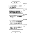
- FIG. 2 is a flowchart showing the operation of the phase unwrap device 1.
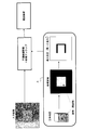
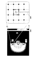
- FIG. 3 is an explanatory diagram for explaining the operations of the coordinate conversion unit 102, the weight determination unit 103, and the discontinuous unit calculation unit 104.
- the coordinate conversion unit 102 extracts the map area corresponding to the shooting area of the SAR image from the three-dimensional map stored in the three-dimensional map storage unit 101, and converts the coordinates of the map area into the coordinates of the SAR image (step S101). ..
- the weight determination unit 103 detects a region in the phase difference image where there is a high possibility of phase discontinuity from the data in the map region whose coordinates have been converted into the coordinates of the SAR image.
- the weight determining unit 103 extracts, for example, a region where the position is discontinuous (for example, a portion where the coordinates in the height direction change significantly) as a region where a phase discontinuity is likely to occur (step S102).
- the discontinuity calculation unit 104 extracts the outline portion of the structure. Is illustrated.
- the weight determination unit 103 assigns a smaller weight to the pixels of the extracted region or between the pixels as compared with the non-extracted region (step S103).
- the weight determining unit 103 imparts a small weight to the contour portion of the structure (see frame A in FIG. 3). Small weights are relatively small weights.
- the weight determining unit 103 assigns 1 to a portion determined that phase discontinuity does not occur, and assigns 0 to a portion determined to cause phase discontinuity.
- the discontinuity calculation unit 104 uses the method as described above, that is, the shortest path connecting the ends that can be regarded as the ends of the region having a large phase difference as the discontinuity boundary (step S104).
- the discontinuity calculation unit 104 refers to the weight between pixels or the distance between pixels to which the weight is added as a product or sum when determining the shortest path. That is, the shortest path is a path that minimizes the weight on the path, or a path that minimizes the total value of the inter-pixel distances evaluated by weighting.
- the distance between pixels with a small weight is referenced, the distance between the pixels is likely to be included in the shortest path. In other words, the fact that pixels or pixels are given a small weight means that the shortest path is likely to include a region where phase discontinuity is likely to occur.
- the weight is a weight calculated by the weight determination unit 103.
- Frame B in FIG. 3 shows an example in which the shortest path is determined for the input image (phase difference image).
- the shortest path includes the contour of the structure as a region where phase discontinuity is likely to occur.
- the contour of the structure is an example of a region where a phase discontinuity is likely to occur, and the region where a phase discontinuity determined based on a stereoscopic image is likely to occur is limited to the contour of the structure. Absent.
- the unwrap processing unit 105 executes phase unwrap by the method described above. That is, the unwrap processing unit 105 sequentially adds the phase differences along the integral path avoiding the discontinuous boundary (step S105). In the configuration example shown in FIG. 1, the unwrap processing unit 105 stores the phase difference image after phase unwrap in the unwrap result storage unit 106.
- the weight determination unit 103 estimates in advance a portion where a discontinuous phase is likely to occur. Then, the weight determining unit 103 assigns a small weight to a portion where a discontinuous phase is likely to occur, so that the portion is easily included in the shortest path (discontinuous boundary).
- the discontinuity calculation unit 104 determines the shortest path, the discontinuity boundary can be estimated more accurately than when the shortest path is simply calculated by taking the given weight into consideration. As a result, the occurrence of unwrap error is suppressed.
- phase unwrap is used in which the phases are integrated (phases are sequentially added) while avoiding discontinuous boundaries.
- the method uses discontinuous boundaries during phase unwrap processing, the phase is phased.
- the idea in the present embodiment can be applied to the phase unwrap that uses a method other than the method of sequentially adding.
- FIG. 4 is a block diagram showing a configuration example of the phase unwrapping device of the second embodiment.
- the phase unwrap device 1 shown in FIG. 4 includes a SAR image storage unit 100, a three-dimensional map storage unit 101, a coordinate conversion unit 102, a weight determination unit 103, a discontinuity calculation unit 104, an unwrap processing unit 108, and an unwrap result storage unit 106. Including.
- the unwrap processing unit 108 in the present embodiment performs phase unwrap by a method different from the method implemented by the unwrap processing unit 105 in the first embodiment.
- the operation of the other components is the same as in the case of the first embodiment.
- phase after the ideal phase unwrap is equal to the phase before the phase unwrap is performed, or is shifted by an integral multiple of 2 ⁇ . More accurately, the value of the difference between the neighboring pixels of the phase before the phase unwrap is equal to the value of the difference before the phase unwrap, or a value deviated by an integral multiple of 2 ⁇ . Further, it is known that in many cases, the assumption that there are few places where the deviation is an integral multiple of 2 ⁇ is established.
- the total value of the magnitude of the difference may be, for example, the total value of the first power of the absolute value of the difference, or the total value of the power of the absolute value of the other difference. Further, it may be the total value obtained by multiplying the absolute value of other differences by a function that monotonically increases.
- the unwrap processing unit 108 uses such a phase unwrap method (hereinafter referred to as a second method).
- a phase unwrap method hereinafter referred to as a second method.
- the unwrap processing unit 108 sets the weight of the pixels of the portion determined by the discontinuity unit calculation unit 104 to be a discontinuous boundary to 0 or a value close to 0, and sets the position between the pixels. Multiply the phase difference by the weight. Further, although a small weight is given to the pixels in the region determined by the weight determining unit 103 that the possibility of phase discontinuity is high, the unwrap processing unit 108 also uses the weight given by the weight determining unit 103. That is, the unwrap processing unit 108 multiplies the pixel that is likely to have a phase discontinuity by the weight given by the weight determining unit 103. After that, the unwrap processing unit 108 executes phase unwrap by the second method.
- phase unwrap when the phase unwrap is performed by the second method, pixels that are likely to cause phase discontinuity are excluded (when the weight is 0), or when the phase unwrap is performed. Since the degree of influence of the pixel, which is likely to cause phase discontinuity, is reduced, the occurrence of an unwrap error is suppressed as in the case of the first embodiment.
- the DSM is stored as a 3D map in the 3D map storage unit 101, but the 3D map that can be used is not limited to the DSM.
- the three-dimensional map storage unit 101 may store a two-dimensional map in which height information is given to each feature as a three-dimensional map.
- the coordinate conversion unit 102 converts the coordinates of the two-dimensional map to which the height information is given for each feature into the coordinates of the SAR image.
- a two-dimensional map having height information for each pixel can be used as the three-dimensional map.
- the coordinate conversion unit 102 converts the coordinates of the two-dimensional map having the height information for each pixel into the coordinates of the SAR image.
- FIG. 5 is an explanatory diagram showing an application example of each of the above embodiments.
- the phase unwrapping device and the phase unwrapping method of the first embodiment or the second embodiment are applied to the displacement analysis using a plurality of (for example, two) SAR images taken at different times. An example is shown.
- the phase unwrap in consideration of the structure in the three-dimensional map is executed, it becomes possible to accurately perform the displacement analysis in the urban area or the urban area.
- Each component in the above embodiment can be configured by one hardware, but can also be configured by one software. Further, each component can be configured by a plurality of hardware and can be configured by a plurality of software. It is also possible to configure a part of each component with hardware and the other part with software.
- Each function (each processing) in the above embodiment can be realized by a computer having a processor such as a CPU (Central Processing Unit) or memory.
- a processor such as a CPU (Central Processing Unit) or memory.
- a program for carrying out the method (processing) in the above embodiment is stored in a storage device (storage medium) and each function is realized by executing the program stored in the storage device on the CPU. Good.
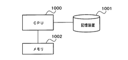
- FIG. 6 is a block diagram showing an example of a computer having a CPU.
- the computer is mounted on a phase unwrap device.
- the CPU 1000 realizes each function in the above embodiment by executing the process according to the program stored in the storage device 1001. That is, the functions of the three-dimensional map storage unit 101, the coordinate conversion unit 102, the weight determination unit 103, the discontinuity unit calculation unit 104, and the unwrap processing units 105 and 108 in the phase unwrap devices 1 and 2 shown in FIGS. 1 and 4. To realize.
- the storage device 1001 is, for example, a non-transitory computer readable medium.
- Non-temporary computer-readable media include various types of tangible storage media (tangible storage medium). Specific examples of non-temporary computer-readable media include magnetic recording media (eg, flexible disks, magnetic tapes, hard disk drives), magneto-optical recording media (eg, magneto-optical disks), and CD-ROMs (Compact Disc-Read Only Memory). ), CD-R (Compact Disc-Recordable), CD-R / W (Compact Disc-ReWritable), semiconductor memory (for example, mask ROM, PROM (Programmable ROM), EPROM (Erasable PROM), flash ROM).
- magnetic recording media eg, flexible disks, magnetic tapes, hard disk drives
- magneto-optical recording media eg, magneto-optical disks
- CD-ROMs Compact Disc-Read Only Memory
- CD-R Compact Disc-Recordable
- CD-R / W Compact
- the program may also be stored on various types of temporary computer-readable media (transitory computer readable medium). Programs are supplied to the temporary computer-readable medium, for example, via a wired or wireless communication path, that is, via an electrical signal, an optical signal, or an electromagnetic wave.
- the memory 1002 is realized by, for example, a RAM (Random Access Memory), and is a storage means for temporarily storing data when the CPU 1000 executes processing.
- a mode in which a program held by the storage device 1001 or a temporary computer-readable medium is transferred to the memory 1002 and the CPU 1000 executes processing based on the program in the memory 1002 can be assumed.
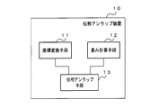
- FIG. 7 is a block diagram showing a main part of the phase unwrap device.
- the phase unwrapping device 10 shown in FIG. 7 includes a coordinate conversion means 11 (in the embodiment, realized by the coordinate conversion unit 102) that converts the coordinates of the map having height information into the coordinates of the SAR image, and the coordinates are SAR. From the map converted to the coordinates of the image, the part where the phase discontinuity can occur in the phase difference image generated from the two SAR images is determined, and the part where the phase discontinuity can occur is weighted.
- the weight calculation means 12 (in the embodiment, realized by the weight determination unit 103) and the phase unwrap means 13 (in the embodiment, the discontinuity calculation unit 104 and the discontinuity unit 104) that perform phase unwrap of the phase difference image using the weights. It is realized by the unwrap processing units 105 and 108).
- Coordinate conversion means for converting the coordinates of a map having height information into the coordinates of a SAR image, and From the map whose coordinates are converted to the coordinates of the SAR image, the portion where the phase discontinuity can occur in the phase difference image generated from the two SAR images is determined, and the portion where the phase discontinuity can occur is determined.
- a weight calculation means for giving weights and
- a phase unwrapping device including a phase unwrapping means for performing phase unwrapping of the phase difference image using the weights.
- the phase unwrapping means is a discontinuity calculation means for calculating a phase discontinuity boundary in the phase difference image using the weight (in the embodiment, it is realized by the discontinuity calculation unit 104).
- the weight calculation means assigns a relatively small weight between pixels in a portion where it is determined that a phase discontinuity can occur.
- the discontinuity calculation means calculates the shortest path between both ends of a region where the phase difference is larger than a predetermined value in consideration of the weight between pixels, and the calculated shortest path is used as the phase discontinuity boundary. 2 phase unwrap device.
- phase unwrapping means (in the embodiment, realized by the unwrapping processing unit 108) performs phase unwrapping by minimizing the difference between the phase before the phase unwrapping and the phase after the phase unwrapping. Phase unwrap device.
- a three-dimensional map storage means for storing the DSM is provided.
- the coordinate conversion means is a phase unwrapping device according to any one of Appendix 1 to Appendix 4 that converts the coordinates of the DSM into the coordinates of the SAR image.
- a three-dimensional map storage means for storing a two-dimensional map to which height information is given to each feature is provided.
- the coordinate conversion means is a phase unwrapping device according to any one of Supplements 1 to 4, which converts the coordinates of the two-dimensional map into the coordinates of the SAR image.
- a three-dimensional map storage means for storing a two-dimensional map having height information for each pixel is provided.
- the coordinate conversion means is a phase unwrapping device according to any one of Supplements 1 to 4, which converts the coordinates of the two-dimensional map into the coordinates of the SAR image.
Landscapes
- Engineering & Computer Science (AREA)
- Remote Sensing (AREA)
- Radar, Positioning & Navigation (AREA)
- Physics & Mathematics (AREA)
- General Physics & Mathematics (AREA)
- Electromagnetism (AREA)
- Computer Networks & Wireless Communication (AREA)
- Theoretical Computer Science (AREA)
- Radar Systems Or Details Thereof (AREA)
- Image Processing (AREA)
Priority Applications (3)
| Application Number | Priority Date | Filing Date | Title |
|---|---|---|---|
| JP2021538553A JP7255690B2 (ja) | 2019-08-05 | 2019-08-05 | 位相アンラップ装置及び位相アンラップ方法 |
| US17/632,343 US20220283294A1 (en) | 2019-08-05 | 2019-08-05 | Phase unwrapping device and phase unwrapping method |
| PCT/JP2019/030637 WO2021024336A1 (ja) | 2019-08-05 | 2019-08-05 | 位相アンラップ装置及び位相アンラップ方法 |
Applications Claiming Priority (1)
| Application Number | Priority Date | Filing Date | Title |
|---|---|---|---|
| PCT/JP2019/030637 WO2021024336A1 (ja) | 2019-08-05 | 2019-08-05 | 位相アンラップ装置及び位相アンラップ方法 |
Publications (1)
| Publication Number | Publication Date |
|---|---|
| WO2021024336A1 true WO2021024336A1 (ja) | 2021-02-11 |
Family
ID=74502873
Family Applications (1)
| Application Number | Title | Priority Date | Filing Date |
|---|---|---|---|
| PCT/JP2019/030637 Ceased WO2021024336A1 (ja) | 2019-08-05 | 2019-08-05 | 位相アンラップ装置及び位相アンラップ方法 |
Country Status (3)
| Country | Link |
|---|---|
| US (1) | US20220283294A1 (cg-RX-API-DMAC7.html) |
| JP (1) | JP7255690B2 (cg-RX-API-DMAC7.html) |
| WO (1) | WO2021024336A1 (cg-RX-API-DMAC7.html) |
Cited By (2)
| Publication number | Priority date | Publication date | Assignee | Title |
|---|---|---|---|---|
| JPWO2022269754A1 (cg-RX-API-DMAC7.html) * | 2021-06-22 | 2022-12-29 | ||
| WO2026063183A1 (ja) * | 2024-09-18 | 2026-03-26 | 日本電気株式会社 | 情報処理装置、情報処理方法及び記録媒体 |
Families Citing this family (2)
| Publication number | Priority date | Publication date | Assignee | Title |
|---|---|---|---|---|
| CN118795476B (zh) * | 2024-06-19 | 2026-06-26 | 中国矿业大学 | 一种相位解缠方法和装置、系统、存储介质 |
| CN118565329B (zh) * | 2024-06-28 | 2024-10-01 | 法博思(宁波)半导体设备有限公司 | 一种跨区域相位解包裹方法、装置及计算机可读存储介质 |
Citations (5)
| Publication number | Priority date | Publication date | Assignee | Title |
|---|---|---|---|---|
| JP2000105275A (ja) * | 1998-09-29 | 2000-04-11 | Mitsubishi Electric Corp | レーダ信号処理装置 |
| JP2001083243A (ja) * | 1999-09-13 | 2001-03-30 | Mitsubishi Electric Corp | 干渉型合成開口レーダによる地形の3次元情報抽出装置 |
| JP2007139543A (ja) * | 2005-11-17 | 2007-06-07 | Fujitsu Ltd | 位相アンラッピング方法、プログラム及び干渉計測装置 |
| JP2010522343A (ja) * | 2007-03-22 | 2010-07-01 | ハリス コーポレイション | 複素干渉測定sarデータを処理する方法および装置 |
| JP2016090361A (ja) * | 2014-11-04 | 2016-05-23 | 国立研究開発法人情報通信研究機構 | Sarインターフェログラムからの垂直構造の抽出方法 |
Family Cites Families (5)
| Publication number | Priority date | Publication date | Assignee | Title |
|---|---|---|---|---|
| JPH09230039A (ja) * | 1996-02-27 | 1997-09-05 | Mitsubishi Electric Corp | 干渉型合成開口レーダ装置及び合成開口レーダ装置を用いた地形高さ測定方法 |
| AU2003286083A1 (en) * | 2003-07-19 | 2005-02-04 | Gamma Remote Sensing Research And Consulting Ag | Method to improve interferometric signatures by coherent point scatterers |
| US7598899B2 (en) * | 2007-03-22 | 2009-10-06 | Harris Corporation | Method and apparatus for compression of SAR images |
| KR101111689B1 (ko) * | 2009-11-03 | 2012-02-14 | 연세대학교 산학협력단 | 3차원 지표 변위 추출 방법 및 그 장치 |
| WO2015160289A1 (en) * | 2014-04-14 | 2015-10-22 | Saab Vricon Systems Ab | Method and system for rendering a synthetic aperture radar image |
-
2019
- 2019-08-05 JP JP2021538553A patent/JP7255690B2/ja active Active
- 2019-08-05 US US17/632,343 patent/US20220283294A1/en not_active Abandoned
- 2019-08-05 WO PCT/JP2019/030637 patent/WO2021024336A1/ja not_active Ceased
Patent Citations (5)
| Publication number | Priority date | Publication date | Assignee | Title |
|---|---|---|---|---|
| JP2000105275A (ja) * | 1998-09-29 | 2000-04-11 | Mitsubishi Electric Corp | レーダ信号処理装置 |
| JP2001083243A (ja) * | 1999-09-13 | 2001-03-30 | Mitsubishi Electric Corp | 干渉型合成開口レーダによる地形の3次元情報抽出装置 |
| JP2007139543A (ja) * | 2005-11-17 | 2007-06-07 | Fujitsu Ltd | 位相アンラッピング方法、プログラム及び干渉計測装置 |
| JP2010522343A (ja) * | 2007-03-22 | 2010-07-01 | ハリス コーポレイション | 複素干渉測定sarデータを処理する方法および装置 |
| JP2016090361A (ja) * | 2014-11-04 | 2016-05-23 | 国立研究開発法人情報通信研究機構 | Sarインターフェログラムからの垂直構造の抽出方法 |
Cited By (4)
| Publication number | Priority date | Publication date | Assignee | Title |
|---|---|---|---|---|
| JPWO2022269754A1 (cg-RX-API-DMAC7.html) * | 2021-06-22 | 2022-12-29 | ||
| WO2022269754A1 (ja) * | 2021-06-22 | 2022-12-29 | 日本電気株式会社 | 画像解析装置および画像解析方法 |
| JP7722453B2 (ja) | 2021-06-22 | 2025-08-13 | 日本電気株式会社 | 画像解析装置および画像解析方法 |
| WO2026063183A1 (ja) * | 2024-09-18 | 2026-03-26 | 日本電気株式会社 | 情報処理装置、情報処理方法及び記録媒体 |
Also Published As
| Publication number | Publication date |
|---|---|
| JP7255690B2 (ja) | 2023-04-11 |
| JPWO2021024336A1 (cg-RX-API-DMAC7.html) | 2021-02-11 |
| US20220283294A1 (en) | 2022-09-08 |
Similar Documents
| Publication | Publication Date | Title |
|---|---|---|
| US12249027B2 (en) | Three-dimensional model generation method, information processing device, and medium | |
| JP7255690B2 (ja) | 位相アンラップ装置及び位相アンラップ方法 | |
| EP3435029B1 (en) | Resolution adaptive mesh for performing 3-d metrology of an object | |
| US20220026568A1 (en) | Methods and Systems for Detection of Objects in a Vicinity of a Vehicle | |
| US9972067B2 (en) | System and method for upsampling of sparse point cloud for 3D registration | |
| CN112771573A (zh) | 基于散斑图像的深度估计方法及装置、人脸识别系统 | |
| EP2901236B1 (en) | Video-assisted target location | |
| CN103472450B (zh) | 基于压缩感知的非均匀空间构形分布式sar动目标三维成像方法 | |
| JP6452586B2 (ja) | 画像処理装置および画像処理方法 | |
| KR101885961B1 (ko) | 이미지를 기반으로 한 객체 위치 추정 방법 및 장치 | |
| US11460573B2 (en) | Synthetic aperture radar signal processing device and method | |
| US11835619B2 (en) | Synthetic aperture radar signal analysis device, synthetic aperture radar signal analysis method, and synthetic aperture radar signal analysis program | |
| CN120044516A (zh) | 一种基于事件相机与毫米波雷达高频融合的地基无人机定位方案 | |
| CN110618409B (zh) | 顾及叠掩及阴影的多通道InSAR干涉图仿真方法及系统 | |
| US20240077605A1 (en) | Change detection device and change detection method | |
| CN114460577B (zh) | 一种考虑天线波束宽度的雷达bp成像方法及系统 | |
| EP4443383A1 (en) | Three-dimensional model generation method and three-dimensional model generation device | |
| CN119247297B (zh) | 一种基于微波视觉的阵列干涉sar误差估计方法与装置 | |
| US11169258B2 (en) | Transport-based synthetic aperture radar navigation systems and methods | |
| JP4855304B2 (ja) | 画像レーダ信号処理装置 | |
| WO2022269754A1 (ja) | 画像解析装置および画像解析方法 | |
| US20210400217A1 (en) | Time-of-flight down-up sampling using a compressed guide | |
| CN117930238A (zh) | 基于最小生成树的sar层析参考网生成方法及装置 | |
| US10580208B2 (en) | Ceiling map building method, ceiling map building device, and ceiling map building program | |
| JP2013104733A (ja) | レーダ画像処理装置 |
Legal Events
| Date | Code | Title | Description |
|---|---|---|---|
| 121 | Ep: the epo has been informed by wipo that ep was designated in this application |
Ref document number: 19940423 Country of ref document: EP Kind code of ref document: A1 |
|
| ENP | Entry into the national phase |
Ref document number: 2021538553 Country of ref document: JP Kind code of ref document: A |
|
| NENP | Non-entry into the national phase |
Ref country code: DE |
|
| 122 | Ep: pct application non-entry in european phase |
Ref document number: 19940423 Country of ref document: EP Kind code of ref document: A1 |