WO2021020339A1 - Dispositif, procédé et programme de génération d'image d'apprentissage, et procédé, dispositif et programme d'apprentissage - Google Patents
Dispositif, procédé et programme de génération d'image d'apprentissage, et procédé, dispositif et programme d'apprentissage Download PDFInfo
- Publication number
- WO2021020339A1 WO2021020339A1 PCT/JP2020/028685 JP2020028685W WO2021020339A1 WO 2021020339 A1 WO2021020339 A1 WO 2021020339A1 JP 2020028685 W JP2020028685 W JP 2020028685W WO 2021020339 A1 WO2021020339 A1 WO 2021020339A1
- Authority
- WO
- WIPO (PCT)
- Prior art keywords
- learning
- image
- teacher data
- model
- variation
- Prior art date
Links
Images


Classifications
-
- G—PHYSICS
- G06—COMPUTING; CALCULATING OR COUNTING
- G06V—IMAGE OR VIDEO RECOGNITION OR UNDERSTANDING
- G06V10/00—Arrangements for image or video recognition or understanding
- G06V10/70—Arrangements for image or video recognition or understanding using pattern recognition or machine learning
- G06V10/82—Arrangements for image or video recognition or understanding using pattern recognition or machine learning using neural networks
-
- G—PHYSICS
- G06—COMPUTING; CALCULATING OR COUNTING
- G06V—IMAGE OR VIDEO RECOGNITION OR UNDERSTANDING
- G06V10/00—Arrangements for image or video recognition or understanding
- G06V10/70—Arrangements for image or video recognition or understanding using pattern recognition or machine learning
- G06V10/77—Processing image or video features in feature spaces; using data integration or data reduction, e.g. principal component analysis [PCA] or independent component analysis [ICA] or self-organising maps [SOM]; Blind source separation
- G06V10/774—Generating sets of training patterns; Bootstrap methods, e.g. bagging or boosting
- G06V10/7747—Organisation of the process, e.g. bagging or boosting
-
- A—HUMAN NECESSITIES
- A61—MEDICAL OR VETERINARY SCIENCE; HYGIENE
- A61B—DIAGNOSIS; SURGERY; IDENTIFICATION
- A61B6/00—Apparatus for radiation diagnosis, e.g. combined with radiation therapy equipment
- A61B6/02—Devices for diagnosis sequentially in different planes; Stereoscopic radiation diagnosis
- A61B6/03—Computerised tomographs
-
- G—PHYSICS
- G06—COMPUTING; CALCULATING OR COUNTING
- G06T—IMAGE DATA PROCESSING OR GENERATION, IN GENERAL
- G06T7/00—Image analysis
- G06T7/0002—Inspection of images, e.g. flaw detection
- G06T7/0012—Biomedical image inspection
-
- G—PHYSICS
- G06—COMPUTING; CALCULATING OR COUNTING
- G06T—IMAGE DATA PROCESSING OR GENERATION, IN GENERAL
- G06T7/00—Image analysis
- G06T7/0002—Inspection of images, e.g. flaw detection
- G06T7/0012—Biomedical image inspection
- G06T7/0014—Biomedical image inspection using an image reference approach
-
- G—PHYSICS
- G06—COMPUTING; CALCULATING OR COUNTING
- G06T—IMAGE DATA PROCESSING OR GENERATION, IN GENERAL
- G06T7/00—Image analysis
- G06T7/10—Segmentation; Edge detection
- G06T7/11—Region-based segmentation
-
- G—PHYSICS
- G06—COMPUTING; CALCULATING OR COUNTING
- G06V—IMAGE OR VIDEO RECOGNITION OR UNDERSTANDING
- G06V10/00—Arrangements for image or video recognition or understanding
- G06V10/40—Extraction of image or video features
- G06V10/44—Local feature extraction by analysis of parts of the pattern, e.g. by detecting edges, contours, loops, corners, strokes or intersections; Connectivity analysis, e.g. of connected components
- G06V10/443—Local feature extraction by analysis of parts of the pattern, e.g. by detecting edges, contours, loops, corners, strokes or intersections; Connectivity analysis, e.g. of connected components by matching or filtering
- G06V10/449—Biologically inspired filters, e.g. difference of Gaussians [DoG] or Gabor filters
- G06V10/451—Biologically inspired filters, e.g. difference of Gaussians [DoG] or Gabor filters with interaction between the filter responses, e.g. cortical complex cells
- G06V10/454—Integrating the filters into a hierarchical structure, e.g. convolutional neural networks [CNN]
-
- G—PHYSICS
- G06—COMPUTING; CALCULATING OR COUNTING
- G06V—IMAGE OR VIDEO RECOGNITION OR UNDERSTANDING
- G06V10/00—Arrangements for image or video recognition or understanding
- G06V10/70—Arrangements for image or video recognition or understanding using pattern recognition or machine learning
- G06V10/74—Image or video pattern matching; Proximity measures in feature spaces
- G06V10/75—Organisation of the matching processes, e.g. simultaneous or sequential comparisons of image or video features; Coarse-fine approaches, e.g. multi-scale approaches; using context analysis; Selection of dictionaries
- G06V10/751—Comparing pixel values or logical combinations thereof, or feature values having positional relevance, e.g. template matching
-
- G—PHYSICS
- G06—COMPUTING; CALCULATING OR COUNTING
- G06V—IMAGE OR VIDEO RECOGNITION OR UNDERSTANDING
- G06V10/00—Arrangements for image or video recognition or understanding
- G06V10/70—Arrangements for image or video recognition or understanding using pattern recognition or machine learning
- G06V10/77—Processing image or video features in feature spaces; using data integration or data reduction, e.g. principal component analysis [PCA] or independent component analysis [ICA] or self-organising maps [SOM]; Blind source separation
- G06V10/778—Active pattern-learning, e.g. online learning of image or video features
- G06V10/7784—Active pattern-learning, e.g. online learning of image or video features based on feedback from supervisors
-
- G—PHYSICS
- G06—COMPUTING; CALCULATING OR COUNTING
- G06T—IMAGE DATA PROCESSING OR GENERATION, IN GENERAL
- G06T2207/00—Indexing scheme for image analysis or image enhancement
- G06T2207/10—Image acquisition modality
- G06T2207/10072—Tomographic images
-
- G—PHYSICS
- G06—COMPUTING; CALCULATING OR COUNTING
- G06T—IMAGE DATA PROCESSING OR GENERATION, IN GENERAL
- G06T2207/00—Indexing scheme for image analysis or image enhancement
- G06T2207/10—Image acquisition modality
- G06T2207/10072—Tomographic images
- G06T2207/10081—Computed x-ray tomography [CT]
-
- G—PHYSICS
- G06—COMPUTING; CALCULATING OR COUNTING
- G06T—IMAGE DATA PROCESSING OR GENERATION, IN GENERAL
- G06T2207/00—Indexing scheme for image analysis or image enhancement
- G06T2207/20—Special algorithmic details
- G06T2207/20016—Hierarchical, coarse-to-fine, multiscale or multiresolution image processing; Pyramid transform
-
- G—PHYSICS
- G06—COMPUTING; CALCULATING OR COUNTING
- G06T—IMAGE DATA PROCESSING OR GENERATION, IN GENERAL
- G06T2207/00—Indexing scheme for image analysis or image enhancement
- G06T2207/20—Special algorithmic details
- G06T2207/20081—Training; Learning
-
- G—PHYSICS
- G06—COMPUTING; CALCULATING OR COUNTING
- G06T—IMAGE DATA PROCESSING OR GENERATION, IN GENERAL
- G06T2207/00—Indexing scheme for image analysis or image enhancement
- G06T2207/20—Special algorithmic details
- G06T2207/20084—Artificial neural networks [ANN]
-
- G—PHYSICS
- G06—COMPUTING; CALCULATING OR COUNTING
- G06T—IMAGE DATA PROCESSING OR GENERATION, IN GENERAL
- G06T2207/00—Indexing scheme for image analysis or image enhancement
- G06T2207/30—Subject of image; Context of image processing
- G06T2207/30004—Biomedical image processing
- G06T2207/30016—Brain
-
- G—PHYSICS
- G06—COMPUTING; CALCULATING OR COUNTING
- G06V—IMAGE OR VIDEO RECOGNITION OR UNDERSTANDING
- G06V2201/00—Indexing scheme relating to image or video recognition or understanding
- G06V2201/03—Recognition of patterns in medical or anatomical images
Definitions
- the present disclosure relates to a learning image generator, a method and a program, and a learning method, a device and a program.
- Japanese Unexamined Patent Publication No. 2019-28650 discloses an image identification device that acquires an input image based on the sensor value of the image pickup device and identifies the input image based on the acquired sensor value by using a classifier having a conversion unit. .. This image identification device can obtain an image suitable for identification by learning the conversion unit based on the learning image based on the sensor value of the image pickup device and the correct answer data given to the learning image, and has high accuracy. Image identification can be realized.
- the image to be input is, for example, a brain image of a brain that has developed a stroke such as subarachnoid hemorrhage, intracerebral hemorrhage, and cerebral infarction
- the diseased area such as the infarcted area and the bleeding area to be segmented is , Shape, size, location of onset, etc. are indefinite.
- the pixel value of the diseased area in the brain image changes depending on the elapsed time from the onset of the disease. Therefore, there are various cases in the brain image, and it is difficult to prepare a learning image that can cover all the various cases. Further, when a learning image that can cover all various cases cannot be prepared, it is difficult to stably operate the model for an unknown image in which the learning image does not exist.
- the present disclosure provides a learning image generation device, a method and a program, and a learning method, a device and a program capable of training a model so that the model can operate stably using a limited number of learning images.
- the first aspect of the present disclosure is an image generation device for learning, in which an image acquisition unit that acquires a learning image and a learning image acquired by the image acquisition unit are input to the model, and the model is output.
- a variation learning image generator that generates a variation learning image by adding variations that deviate from the target value to the pixel values of at least one pixel constituting the learning image.
- the learning image is a brain image and the output of the model is 0 or more and less than 0.5, it is determined that there is no cerebral infarction, and when it is 0.5 or more and 1 or less, it is determined that there is a cerebral infarction.
- a model classification discrimination model
- the learning image is an image with an infarct. Since this image is an image with an infarction, “1” determined to have the highest possibility of having an infarction is the “target value” of the present disclosure.
- the “variation away from the target value” is a value at which the output of the model is farther from “1” and is 0.5 or more and less than 0.6.
- the learning image is an image without infarction. Since this image is an image without infarction, “0” determined to have the highest possibility of no infarction is the “target value” of the present disclosure. Therefore, the “variation away from the target value” is a value at which the output of the model is farther from “0” and is greater than 0.3 and less than 0.5.
- the learning image is a brain image and the model is output for each pixel constituting the learning image
- the model output is 0 or more and less than 0.5
- a model segmentation discrimination model in which the pixel does not belong to the cerebral infarction region and is determined to belong to the cerebral infarction region when 0.5 or more and 1 or less is used.
- this pixel is a pixel belonging to the infarcted region. Since this pixel belongs to the infarcted region, “1” determined to be most likely to belong to the infarcted region is the “target value” of the present disclosure.
- the "variation away from the target value” is a value at which the output of the model is farther from “1” and is 0.5 or more and less than 0.6.
- this pixel is a pixel that does not belong to the infarct region. Since this pixel does not belong to the infarct region, “0” determined to be most likely not to belong to the infarct region is the “target value” of the present disclosure. Therefore, the “variation away from the target value” is a value at which the output of the model is farther from “0” and is greater than 0.3 and less than 0.5.
- the variation learning image generation unit acquires the gradient of the output value with respect to the pixel value of each pixel constituting the learning image, and uses the acquired gradient. Fluctuations may be added.
- a third aspect of the present disclosure includes, in the above aspect, a teacher data acquisition unit that acquires teacher data in which a learning image and a correct answer learning image in which a correct answer region is defined in the learning image are combined, and varies.
- the learning image generation unit determines the pixel of interest using the correct learning image of the teacher data acquired by the teacher data acquisition unit, acquires the gradient of the output value of the determined pixel of interest, and obtains the acquired gradient. May be used to add variation.
- the variation learning image generation unit may determine the pixels in the learning image corresponding to the pixels belonging to the correct answer region as the pixels of interest.
- the variation learning image generation unit may determine the pixels in the learning image corresponding to the pixels belonging to the area other than the correct answer region as the pixels of interest. ..
- the variation learning image generation unit determines the pixels in the learning image corresponding to the pixels belonging to the center of gravity of the correct answer region as the pixels of interest. You may.
- the variation learning image generation unit has a plurality of output units in which the model classifies the input learning image into a plurality of classes including one or more correct answer classes.
- the gradient of the output value output from the output unit classified into the correct answer class may be acquired.
- the eighth aspect of the present disclosure is a learning image generation method, in which, when a learning image is acquired and the acquired learning image is input to the model, the output of the model deviates from the target value.
- a variable learning image is generated by adding it to the pixel value of at least one pixel constituting the learning image.
- a ninth aspect of the present disclosure is a learning image generation program, in which an image acquisition unit that acquires a learning image and a learning image acquired by the image acquisition unit are input to the model, and the model is output.
- the computer functions as a variation learning image generation unit that generates a variation learning image by adding a variation that deviates from the target value to the pixel value of at least one pixel constituting the learning image.
- a learning image generator comprising a memory for storing instructions to be executed by a processor and a processor configured to execute the stored instructions. Fluctuation learning is performed by adding a variation in which the output of the model deviates from the target value to the pixel value of at least one pixel constituting the learning image when the acquired image is acquired and the acquired learning image is input to the model. Execute the process to generate the image for use.
- the tenth aspect of the present disclosure is a learning method, in which one or more first teacher data in which a learning image and correct answer information in the learning image are paired, and a learning image are input to a model.
- one or more variation learning images and one or more variation learning images generated by adding fluctuations in which the output of the model deviates from the target value to the pixel values of at least one pixel constituting the learning image, respectively.
- the model is trained using one or more second teacher data in combination with the correct answer information in the learning image before the change.
- the correct answer information may be a correct answer learning image in which a correct answer region is defined in the learning image.
- the model is trained using the plurality of first teacher data in the first learning, and the plurality of first learnings are performed in the second and subsequent learnings. At least one of the teacher data, the first teacher data, may be replaced with the second teacher data to train the model.
- the model is trained using the plurality of first teacher data in the first learning, and at least one first in the second and subsequent learnings. 2 Teacher data may be added to train the model.
- At least one of the second teacher data and the number of the second teacher data to be used is randomly selected for each learning in the second and subsequent learnings. May be set to.
- At least one of the number of the second teacher data and the number of the second teacher data to be used in the second and subsequent learnings may be set in advance in the twelfth or thirteenth aspect.
- the model may be trained using only the plurality of first teacher data at least once in the second and subsequent learnings.
- the seventeenth aspect of the present disclosure is a learning device, in which one or more first teacher data in which a learning image and correct answer information in the learning image are paired, and a learning image are input to a model.
- one or more variation learning images and one or more variation learning images generated by adding fluctuations in which the output of the model deviates from the target value to the pixel values of at least one pixel constituting the learning image, respectively.
- the teacher data acquisition unit that acquires one or more second teacher data that is a combination of the correct answer information in the learning image before the change, and one or more first teacher data and one or more acquired by the teacher data acquisition unit. Includes a learning unit that trains a model using the second teacher data of.
- a learning apparatus comprising a memory for storing instructions to be executed by a processor and a processor configured to execute the stored instructions, wherein the processor is a learning image.
- the eighteenth aspect of the present disclosure is a learning device, and the learning unit can train the model by the learning method in the tenth to sixteenth aspects.
- the nineteenth aspect of the present disclosure is a learning program in which one or more first teacher data in which a learning image and correct answer information in the learning image are paired, and a learning image are input to a model.
- one or more variation learning images and one or more variation learning images generated by adding fluctuations in which the output of the model deviates from the target value to the pixel values of at least one pixel constituting the learning image, respectively.
- the teacher data acquisition unit that acquires one or more second teacher data that is a combination of the correct answer information in the learning image before the change, and one or more first teacher data and one or more acquired by the teacher data acquisition unit.
- the computer is made to function as a learning unit for learning a model using the second teacher data of.
- the correct answer information may be a correct answer learning image in which a correct answer region is defined in the learning image.
- the learning image generator, method and program of the present disclosure, and the learning method, device and program use limited learning images to train a model so that they can operate stably. Can be done.
- a flowchart showing a process of generating a fluctuating CT image A diagram for explaining the second teacher data, which is a combination of a variable CT image and correct answer information.
- Diagram to explain the learning model The figure for demonstrating the learning method using the 1st teacher data and the 2nd teacher data in 2nd exemplary embodiment.
- Flowchart showing the processing performed during learning The figure for demonstrating the learning method using the 1st teacher data and the 2nd teacher data in a 3rd exemplary embodiment.
- the figure for demonstrating the learning method using the 1st teacher data and the 2nd teacher data in a 4th exemplary embodiment.
- the figure for demonstrating the first teacher data which combined the CT image and the correct CT image.
- a flowchart showing a process of generating a fluctuating CT image The figure for demonstrating the 2nd teacher data which combined the variation CT image and the correct answer CT image.
- FIG. 1 is a hardware configuration diagram showing an outline of a diagnosis support system to which a learning image generation device and a learning device according to the first exemplary embodiment of the present disclosure are applied.
- the learning device 1 in the diagnosis support system, the learning device 1, the three-dimensional image capturing device 2, and the image storage server 3 according to this exemplary embodiment are connected via the network 4 in a communicable state.
- the learning device 1 includes a learning model and a learning image generation device according to this exemplary embodiment.
- the three-dimensional imaging device 2 is a device that generates a three-dimensional image representing the site by photographing the site to be diagnosed of the subject, and specifically, a CT (Computed Tomography) device, an MRI ( Magnetic Resonance Imaging) equipment, PET (Positron Emission Tomography) equipment, and the like.
- the medical image generated by the three-dimensional image capturing device 2 is transmitted to the image storage server 3 and stored.
- the diagnosis target site of the patient who is the subject is the brain, and the three-dimensional imaging device 2 is a CT device. Then, in the CT apparatus, a three-dimensional CT image Bc0 including the brain of the subject is generated.
- the image storage server 3 is a computer that stores and manages various data, and is equipped with a large-capacity external storage device and database management software.
- the image storage server 3 communicates with another device via a wired or wireless network 4 to send and receive image data and the like.
- various data including image data of CT images generated by the three-dimensional image capturing device 2 are acquired via a network and stored in a recording medium such as a large-capacity external storage device for management.
- the storage format of the image data and the communication between the devices via the network 4 are based on a protocol such as DICOM (Digital Imaging and Communication in Medicine).
- DICOM Digital Imaging and Communication in Medicine
- the image storage server 3 also stores and manages the first teacher data D (described later) including the CT image Bc0 which is a learning image for learning the learning model 22 described later. doing.
- the learning device 1 including the learning image generation device and the learning model of the present exemplary embodiment is a computer in which the learning image generation program and the learning program of the present disclosure are installed.
- the computer may be a workstation or personal computer directly operated by the diagnosing doctor, or a server computer connected to them via a network.
- the learning image generation program and the learning program are recorded and distributed on a recording medium such as a DVD (Digital Versatile Disc) or a CD-ROM (Compact Disc Read Only Memory), and are installed on a computer from the recording medium.
- a recording medium such as a DVD (Digital Versatile Disc) or a CD-ROM (Compact Disc Read Only Memory)
- it is stored in a storage device of a server computer connected to a network or in a network storage in a state of being accessible from the outside, and is downloaded and installed in a computer used by a doctor upon request.
- FIG. 2 is a diagram showing a schematic configuration of a learning device 1 which is an exemplary embodiment of the present disclosure realized by installing a learning image generation program and a learning program on a computer.
- the learning device 1 includes a CPU (Central Processing Unit) 11, a memory 12, and a storage 13 as a standard workstation configuration. Further, the learning device 1 is connected to a display unit 14 including a liquid crystal display and the like, and an input unit 15 including a keyboard and a mouse.
- the input unit 15 receives various setting inputs by the user. By using the touch panel, the display unit 14 and the input unit 15 may be used in combination.
- the storage 13 includes a hard disk drive, an SSD (Solid State Drive), and the like.
- the storage 13 stores the first teacher data D including the CT image Bc0, which is a learning image for learning the learning model 22, acquired from the image storage server 3 via the network 4, and the information necessary for processing. Various information including is stored.
- the learning image generation program and the learning program are stored in the memory 12.
- the learning image generation program defines an image acquisition process for acquiring a learning image and an image generation process for variable learning as processes to be executed by the CPU 11.
- the variation learning image generation process when the acquired learning image is input to the learning model 22, the variation that the output of the learning model 22 deviates from the target value is the pixel value of at least one pixel constituting the learning image.
- An image for variable learning is generated by adding to.
- one or more first teacher data in which a learning image and a correct answer learning image in which a correct answer region is defined in the learning image are combined, and a learning image.
- Teacher data acquisition processing to acquire one or more second teacher data in combination with the correct answer learning image in which the correct answer region is defined in the learning image before fluctuation in each of the fluctuation learning images, the acquired one or more
- a training process for training a model using the first teacher data and one or more second teacher data a training image, or a target image to be discriminated is input, the discriminant result in the input image is output.
- the discrimination process to be performed, and the display control process for displaying the learning image, the variation learning image, the discrimination result, and the like on the display unit 14 are defined.
- the computer has the image acquisition unit 20, the teacher data acquisition unit 21, the learning model 22, the variation learning image generation unit 23, the learning unit 24, and the display control unit 25.
- the image acquisition unit 20 and the variation learning image generation unit 23 constitute the learning image generation device of this exemplary embodiment.
- the display control unit 25 causes the display unit 14 to display the CT image Bc0 acquired by the image acquisition unit 20, the variable CT image Bc2 described later, the discrimination result, and the like.
- the image acquisition unit 20 acquires the CT image Bc0 from the image storage server 3 via an interface (not shown) connected to the network.
- FIG. 3 is a diagram for explaining the first teacher data F in which the CT image Bc0 and the correct answer information J0 are combined.
- the CT image Bc0 shown in FIG. 3 is a learning image for learning the learning model 22 described later.
- the CT image Bc0 is a three-dimensional image, but here, for the sake of explanation, a two-dimensional tomographic image on one tomographic plane of the CT image Bc0 will be used.
- the image acquisition unit 20 may acquire the CT image Bc0 from the storage 13.
- the image acquisition unit 20 acquires CT images Bc0 of a large number of subjects for learning the learning model 22 described later.
- the teacher data acquisition unit 21 acquires the first teacher data D from the image storage server 3 via an interface (not shown) connected to the network.
- the first teacher data D is data in which the CT image Bc0 and the information indicating “with infarction” or “without infarction” as the correct answer information J0 in the CT image Bc0 are combined.
- the correct answer information J0 of "with infarction” or “without infarction” may be manually input by the user from the input unit 15.
- the discrimination result based on the output value S (x) of the learning model 22 with respect to the entire CT image Bc0 x is "there is an infarcted region" (Table 1). (See), the CT image Bc0 may be an image of "with infarction".
- the learning model 22 determines the presence or absence of a diseased region in the CT image Bc0. That is, it is a model for discriminating the classification of CT image Bc0 (whether or not there is a disease region).
- the disease area is defined as an infarct area as an example.
- the learning model 22 is a model in which a plurality of processing layers are hierarchically connected and deep learning is performed.
- FIG. 4 is a diagram showing an example of the learning model 22.
- the learning model 22 corresponds to the model of the present disclosure.
- the learning model 22 includes an input unit L including three input layers, a first processing unit L2 including four processing layers, a second processing unit L3 including four processing layers, and one output. It is configured to have an output unit L4 including a layer.
- Each input layer, processing layer, and output layer are connected as shown in FIG.
- the first processing unit L2 and the second processing unit L3 use the data set of the CT image Bc0 of a large number of brains including the infarcted region and the correct answer information which is the discrimination result in the CT image Bc0 as teacher data. It is learned to output an output value S (x) indicating a determination result of having an infarcted region or not having an infarcted region for the entire input CT image Bc0 x.
- the correct answer information is information on whether or not there is an infarcted region in the entire CT image Bc0 x.
- an output value S (x) indicating a determination result of having an infarcted region or not having an infarcted region in the entire CT image Bc0 x is output from the output layer of the output unit L4.
- the output value S (x) output by the output unit L4 is a value indicating a determination result of whether or not there is an infarcted region for the entire CT image Bc0 x.
- Table 1 below shows an example of the output value S (x) and the discrimination result by the learning model 22.
- the output value S (x) of the learning model 22 is 0 or more and less than 0.5, it is determined that there is no infarct region, and when it is 0.5 or more and 1 or less, it is determined that there is an infarction. That is, for example, when the CT image Bc0 is input to the learning model 22, if the output value S (x) of the learning model 22 is 0.6, the CT image Bc0 has an infarcted region. Further, when the CT image Bc0 is input to the learning model 22, if the output value S (x) of the learning model 22 is 0.3, the CT image Bc0 has no infarcted region.
- the variation learning image generation unit 23 adds a variation in which the output of the learning model 22 deviates from the target value to the pixel values of at least one pixel constituting the CT image Bc0.
- a variable CT image Bc2 is generated. For example, when the output value S (x) of the learning model 22 is 0.6 for the CT image Bc0 before the fluctuation, it is determined that the CT image Bc0 has an infarcted region. Since this CT image Bc0 is an image with an infarcted region, “1”, which is an output value S (x) determined to have the highest possibility of having an infarcted region, is the “target value”.
- the “variation away from the target value” is a value at which the output value S (x) of the learning model 22 is farther from “1” (lower than “1”), and is 0.5 or more and less than 0.6. It is a variation added to the pixel value so that it becomes a value.
- the CT image Bc0 is an image without an infarcted region. Since this CT image Bc0 is an image without infarction, “0”, which is an output value S (x) determined to have the highest possibility of having no infarction region, is the “target value”.
- the "fluctuation away from the target value” is a value at which the output value S (x) of the learning model 22 is farther from "0", and is a pixel value so as to be a value larger than 0.3 and less than 0.5. It is a fluctuation added to.
- the variation learning image generation unit 23 has a gradient M (x) of the output value S (x) of the learning model 22 with respect to the entire CT image Bc0 x when the CT image Bc0 is first input to the learning model 22.
- the gradient M (x) of the output value S (x) of the learning model 22 with respect to the entire CT image Bc0 x is derived by the following equation (1).
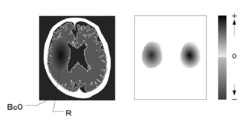
- FIG. 5 is a diagram for explaining the gradient M (x).
- the left figure of FIG. 5 is an example of the CT image Bc0, and the right figure is a diagram in which the values of the gradient M (x) in the CT image Bc0 shown in the left figure are plotted.
- the left figure of FIG. 5 there is a black region on the left side of the image as compared with the right side. This black area shows the findings of cerebral infarction R.
- the area shown by the diagonal line on the left side that is, the gradient M (x) on the side of the area where the cerebral infarction R is found is a negative value, and the area shown in color other than the diagonal line on the right side. That is, the gradient M (x) on the region side where there is no finding of cerebral infarction is a positive value. Further, as the color becomes darker, the absolute value of the gradient M (x) increases.
- the output value S (x) of the learning model 22 increases as the pixel value decreases. .. That is, as the pixel value becomes smaller in the area indicated by the diagonal line on the left side, the area becomes blacker and the output increases. In other words, it is more like a case of cerebral infarction.
- the output value S (x) of the learning model 22 increases as the pixel value increases. That is, in the colored region other than the shaded area on the right side, the larger the pixel value, the whiter the region becomes, and when the left and right regions are compared, the region side where the cerebral infarction R is found becomes relatively blacker, so that the output increases. In other words, it is more like a case of cerebral infarction.
- a variable CT image Bc2 is generated by adding variations to the pixel values of the pixels constituting the CT image Bc0 according to the following equation (2). ..
- xa x-k x M (x) ... (2)
- the constant is k> 0.
- xa indicates the entire variation CT image Bc2 after the entire CT image Bc0 x is varied.
- k ⁇ M (x) represents the entire gradient image shown in the right figure of FIG.
- the variation learning image generation unit 23 subtracts the entire gradient image k ⁇ M (x) shown in the right figure of FIG. 5 from the entire CT image Bc0 x shown in the left figure of FIG. 5, thereby causing the CT image Bc0.
- the pixel value of the pixels constituting the above is changed.
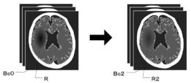
- FIG. 6 is a diagram for explaining the variation CT image Bc2 generated by adding variation to the CT image Bc0.
- the variation learning image generation unit 23 subtracts the entire gradient image k ⁇ M (x) from the entire CT image Bc0 x, as shown in FIG. 6, the region where the cerebral infarction R is found in the CT image Bc0.
- the pixel value is added and the output decreases. Therefore, in the variable CT image Bc2, the black color of the region R2 corresponding to the cerebral infarction R is weakened, which makes it less likely to be a case of cerebral infarction. Further, in the region on the CT image Bc0 opposite to the side where the cerebral infarction R is found, the pixel value is deducted and the output is increased. Therefore, in the variable CT image Bc2, the region corresponding to the side opposite to the cerebral infarction R becomes more black, which makes it more like a case of cerebral infarction.
- the learning model 22 by adding a variation away from the "target value" to the entire CT image Bc0 x, the learning model 22 generates a variable CT image Bc2 in which it is difficult for the learning model 22 to correctly recognize the infarct region as compared with the CT image Bc0 before the variation. be able to.
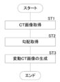
- FIG. 7 is a flowchart showing a process of generating the variable CT image Bc2.
- the image acquisition unit 20 acquires the CT image Bc0 (step ST1).
- the variation learning image generation unit 23 acquires the gradient M (x) of the output value S (x) of the learning model 22 with respect to the entire CT image Bc0 x when the CT image Bc0 is input to the learning model 22. (Step ST2).
- the variation learning image generation unit 23 generates a variation CT image Bc2 by adding a variation away from the “target value” to the entire CT image Bc0 x (step ST3), and a series of processes. Ends the processing of.
- the learning image generation device of this exemplary embodiment composed of the image acquisition unit 20 and the variation learning image generation unit 23, the learning image generation method of this exemplary embodiment, and the learning image of this exemplary embodiment.
- the generation program by adding a variation away from the "target value" to the entire CT image Bc0 x, it is difficult for the learning model 22 to correctly recognize the infarcted region as compared with the CT image Bc0 before the variation.
- Bc2 can be generated. Further, by changing the value of k in the above formula (2), it is possible to generate a plurality of variable CT images Bc2 having different pixel values of the pixels constituting the CT image Bc0.
- variable CT image Bc2 which is a CT image other than the limited CT image Bc0
- the learning model 22 can be trained so that it can operate stably.
- a predetermined constant value may be used, or the value may be randomly changed and used. Further, as will be described later, when the learning model 22 is trained, it may be changed according to the progress of learning. Further, an upper limit value may be set for the value of k in the above formula (2). This makes it possible to prevent the variable CT image Bc2 from becoming an abnormal image. In this case, the upper limit value can be set according to, for example, a possible value of the pixel value.
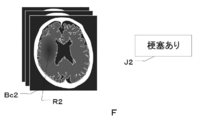
- FIG. 8 is a diagram for explaining the second teacher data F in which the variable CT image Bc2 and the correct answer information J2 are combined.
- the second teacher data F is data in which the fluctuation CT image Bc2 and the information indicating “with infarction” or “without infarction” are combined as the correct answer information J2 in the CT image Bc0 before the fluctuation. is there.
- the correct answer information J2 of "with infarction” or "without infarction” may be manually input by the user from the input unit 15.
- the discrimination result based on the output value S (x) of the learning model 22 with respect to the entire CT image Bc0 x before the change is "there is an infarcted area".
- the fluctuating CT image Bc2 in which the CT image Bc0 is fluctuated may be used as the “with infarction” image.
- FIG. 9 is a diagram for explaining a learning method of the learning model.
- the learning model 22 corresponds to the model of the present disclosure.
- the learning unit 24 inputs the first teacher data D, that is, the CT image Bc0 and the correct answer information J0 into the learning model 22, so that the learning model 22 learns the presence or absence of the infarcted region in the CT image Bc0. ..
- the learning unit 24 inputs the second teacher data F, that is, the variable CT image Bc2 and the correct answer information J2 into the learning model 22, so that the learning model 22 learns the presence or absence of the infarcted region in the variable CT image Bc2.
- the learning model 22 is trained so that the presence or absence of the infarcted region in the variable CT image Bc2 is output.
- n teacher data are trained by the learning model 22 in order.
- the learning model 22 is made to learn the n teacher data again in order for the second time, and the same teacher data is used for a predetermined number of times to repeat the learning model 22. Is being trained.
- FIG. 10 is a diagram for explaining a learning method using the first teacher data D and the second teacher data F in the second exemplary embodiment.
- the first teacher data D and the second teacher data F are a set of CT image Bc0 or variable CT image Bc2 and correct answer information J0 or correct answer information J2, that is, they are composed of two data.
- the first teacher data D and the second teacher data F are represented by one image for convenience of explanation. It may be expressed in the same manner in the following drawings.
- the learning unit 24 trains the learning model 22 using n first teacher data D1 to Dn at the time of the first learning (1T).
- the learning model 22 is trained by replacing the first teacher data D1 with the second teacher data F1.
- the second teacher data F1 is returned to the first teacher data D1
- the first teacher data D2 is replaced with the second teacher data F2 to train the learning model 22.
- the second teacher data F2 is returned to the first teacher data D2, and the first teacher data D3 is replaced with the second teacher data F3 to train the learning model 22.
- the first teacher data D of one of n first teacher data D1 to Dn is used as the second teacher data for each learning.
- the learning model 22 is trained instead of F.
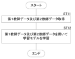
- FIG. 11 is a flowchart showing the processing performed at the time of learning.
- the teacher data acquisition unit 21 acquires the first teacher data D and the second teacher data F from the image storage server 3 and the storage 13 (step ST11).
- the learning unit 24 trains the learning model 22 as described above using the acquired first teacher data D and the second teacher data F (step ST12), and ends a series of processes.
- the correct answer is the variation CT image Bc2 generated by adding the variation in which the output of the model deviates from the "target value" with respect to the entire CT image Bc0 x to the pixels constituting the CT image Bc0.
- the second teacher data F in combination with the information J2 is used for learning.
- the variable CT image Bc2 which is a CT image other than the limited CT image Bc0 Can also be used as a learning image. That is, using the limited CT image Bc0, the learning model 22 can be trained so that it can operate stably even for an unknown CT image other than the CT image Bc0.
- one first teacher data D is replaced with the second teacher data F to train the learning model 22, but the present disclosure shows.
- Technology is not limited to this.
- the two first teacher data D may be replaced with the second teacher data F, or any number of first teacher data D such as three or four may be replaced with the second teacher data F.
- only the predetermined first teacher data D may be replaced with the second teacher data F which is different each time.
- the first teacher data D to be changed to the second teacher data F may be randomly selected.
- the number of the first teacher data D to be changed to the second teacher data F may be randomly determined.
- FIG. 12 is a diagram for explaining a learning method using the first teacher data D and the second teacher data F in the third exemplary embodiment.
- the learning unit 24 trains the learning model 22 using n first teacher data D1 to Dn at the time of the first learning (1T).
- the learning model 22 is trained by replacing the first teacher data D1 with the second teacher data F1.
- the second teacher data F1 is returned to the first teacher data D1
- the first teacher data D2 is returned to the second teacher data F2
- the first teacher data D4 is changed to the second teacher.
- the data F4 is replaced with the first teacher data D5 and the second teacher data F5 to train the learning model 22.
- the second teacher data F2 becomes the first teacher data D2
- the second teacher data F4 becomes the first teacher data D4
- the second teacher data F5 becomes the first teacher data D5.
- the learning model 22 is trained by replacing the first teacher data D1 with the second teacher data F1 and the first teacher data D3 with the second teacher data F3.
- the learning model 22 is trained by replacing the first teacher data D with the second teacher data F each time in the second and subsequent learnings.
- the learning model 22 may be trained by adding the second teacher data F to the n first teacher data Dn each time.
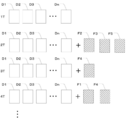
- FIG. 13 is a diagram for explaining a learning method using the first teacher data D and the second teacher data F in the fourth exemplary embodiment.
- the learning unit 24 trains the learning model 22 using n first teacher data D1 to Dn at the time of the first learning (1T).
- the second teacher data F1 is added to train the learning model 22.
- the second teacher data F2 is added to train the learning model 22.
- the second teacher data F3 is added to train the learning model 22.
- a learning model is added by adding one second teacher data F to the n first teacher data D1 to Dn each time. 22 is trained.
- n + 1 learning is completed, the process returns to the first learning (1T), and the above learning is repeated until the set number of learning is completed.
- the learning model 22 is trained by adding one second teacher data F each time in the second and subsequent learnings, but the technique of the present disclosure is not limited to this. .. Two second teacher data Fs may be added, or any number of second teacher data Fs, such as three or four, may be added. Further, the second teacher data F to be added may be randomly selected.
- FIG. 14 is a diagram for explaining a learning method using the first teacher data D and the second teacher data F in the fifth exemplary embodiment.
- the learning unit 24 trains the learning model 22 using n first teacher data D1 to Dn at the time of the first learning (1T).
- the second teacher data F2, the second teacher data F3, and the second teacher data F5 are added to train the learning model 22.
- the second teacher data F4 is added to train the learning model 22.
- the second teacher data F1 and the second teacher data F4 are added to train the learning model 22.
- a random number of second teacher data Fs are added to n first teacher data D1 to Dn each time.
- the learning model 22 is trained until the set number of learnings is completed.
- FIG. 15 is a diagram for explaining a learning method using the first teacher data D and the second teacher data F in the sixth exemplary embodiment.
- the learning unit 24 uses only n first teacher data D1 to Dn at least once in the second and subsequent learnings, and in the seventh learning in this exemplary embodiment.
- the learning model 22 is trained.
- the number of times the learning model 22 is trained using only n first teacher data D1 to Dn is not limited to the seventh time, and may be any time. Further, the learning model 22 may be trained using only the first teacher data D1 to Dn twice, three times, and n times.
- the second teacher data F may use the variable CT image Bc2 in which the value of k in the above formula (2) is changed and varied each time.
- the value of k may be randomly changed each time, or may be a predetermined value.
- the first teacher data D is the teacher data in which the CT image Bc0 and the correct answer information J0 are paired
- the second teacher data F is the variable CT image Bc2 and the correct answer information J2.
- FIG. 16 is a diagram for explaining the first teacher data D-2 in which the CT image Bc0 and the correct CT image Bc1 are combined.
- the first teacher data D includes a CT image Bc0 which is a learning image for learning the learning model 22 and a correct mask Bc1 in which an infarct region A is defined as a correct region in the CT image Bc0. It is the teacher data that is a set of.
- the correct answer mask Bc1 is defined by painting the infarct region A, which is the correct answer region, in white, but the correct answer mask Bc1 is not limited to this.
- the infarct region A may be defined by drawing the boundary of the infarct region A in white without filling the inside of the infarct region A. Further, it may be drawn in a color other than white. Further, the infarct region A may be defined by forming an image in which the inside of the infarct region A and the outside of the infarction region A are composed of pixels having different pixel values.
- the CT image Bc0 of the present exemplary embodiment corresponds to the learning image of the present disclosure
- the correct answer mask Bc1 of the present exemplary embodiment corresponds to the correct answer learning image of the present disclosure.
- the teacher data acquisition unit 21 acquires the first teacher data D-2 from the storage 13. You may try to do it.
- the teacher data acquisition unit 21 acquires the first teacher data D-2 for a large number of subjects for learning the learning model 22-2 described later.
- the variation learning image generation unit 23 applies the CT image Bc0 to the learning model 22-2 (model shown in FIG. 17), which will be described later, with respect to the pixel of interest determined by using the correct mask Bc1.
- the output of the learning model 22-2 is changed to deviate from the target value.
- the learning model 22-2 will be described. The method of determining the pixel of interest will be described in detail later.
- the learning model 22-2 determines the presence or absence of an infarcted region for each pixel constituting the CT image Bc0. That is, it is a model for discriminating the segmentation of the CT image Bc0. Specifically, it is a model learned to output the correct answer mask Bc1 in which the infarct region A in the CT image Bc0 is defined when the CT image Bc0 to be detected in the infarct region A is input.
- the learning model 22-2 has a U-Net (U Networks) structure.
- U-Net is one of the full-layer convolutional networks (FCNs) and is a network specialized in image segmentation.
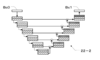
- FIG. 17 is a diagram showing an example of a learning model 22-2 having a U-Net structure.
- the layer indicated by diagonal lines is a convolution layer
- the layer indicated by dots is a pooling layer
- the layer indicated by a grid is an upsampling layer.
- the arrows circled indicate that the image sizes are the same and integrated.
- the downward path (downward arrow in the figure) outputs a feature map in which the amount of data is reduced by the convolution process and the pooling process.
- the upward path (upward arrow in the figure) is output by greatly restoring the size of the feature map by the convolution process and the upsampling process.
- the learning model 22-2 restores the overall position information while preserving the local features by gradually integrating images of the same image size from the deep layers in both paths.
- the learning model 22-2 of this exemplary embodiment can use a known U-Net structure.
- the correct mask Bc1 in which the infarct region A in the CT image Bc0 is defined is obtained from the learning model 22-2. Learning is done so that it is output.
- the correct answer mask Bc1 has an output value of whether each pixel constituting the CT image Bc0 is a pixel belonging to the infarct region or a pixel belonging to a region other than the infarct region.
- the output value of whether a pixel of interest (hereinafter referred to as a pixel of interest) belongs to an infarct region or a pixel other than the infarct region is defined as an output value Ss (x).
- Table 2 below shows an example of the output value Ss (x) and the discrimination result by the learning model 22-2.
- the output value Ss (x) of the learning model 22-2 is 0 or more and less than 0.5, it is determined as a pixel other than the infarct region, and when it is 0.5 or more and 1 or less, it is determined as a pixel in the infarct region. That is, for example, when the CT image Bc0 is input to the learning model 22-2 and the output value Ss (x) of the attention pixel of the learning model 22-2 is 0.6, the attention pixel belongs to the infarct region. It becomes a pixel.
- this attention pixel belongs to a region other than the infarct region. It becomes a pixel.
- the variation learning image generation unit 23 adds a variation in which the output of the attention region of the learning model 22-2 deviates from the target value to the pixel value of the pixel of interest. Generates a variable CT image Bc2. For example, when the output value Ss (x) of the attention pixel of the learning model 22-2 is 0.6 for the CT image Bc0 before the fluctuation, the attention pixel is determined to belong to the infarcted region. Therefore, “1”, which is the output value Ss (x) determined to be the pixel most likely to belong to the infarct region in the pixel of interest, is the “target value”.
- the "fluctuation away from the target value” is a value at which the output value Ss (x) of the pixel of interest of the learning model 22-2 is farther from “1" (lower than “1"), and is 0.5 or more. It is a variation added to the pixel value so that the value is less than 0.6.
- the output value Ss (x) of the attention pixel of the learning model 22-2 is 0.3 for the CT image Bc0 before the fluctuation, the attention pixel is determined to belong to a pixel other than the infarct region.
- the variation learning image generation unit 23 first inputs the CT image Bc0 to the learning model 22-2, and the gradient Ms (x) of the output value Ss (x) of the learning model 22-2 with respect to the pixel of interest s ( x) is acquired.
- the gradient Ms (x) of the output value Ss (x) of the learning model 22-2 with respect to the pixel of interest is derived by the following equation (3).
- a variable CT image Bc2 is generated by adding variations to at least one pixel constituting the CT image Bc0 according to the following equation (4). ..
- x indicates the entire CT image Bc0
- xa indicates the entire variation CT image Bc2 after the CT image Bc0 is changed.
- k ⁇ Ms (x) represents the entire gradient image as in the right figure of FIG.
- the variation learning image generation unit 23 gives variation to at least one pixel constituting the CT image Bc0 by subtracting the entire gradient image k ⁇ Ms (x) from the entire CT image Bc0 x. Image Bc2 is generated.
- the variation learning image generation unit 23 first detects the pixel to which the center of gravity G of the infarct region A defined in the correct answer mask Bc1 belongs.
- FIG. 18 is a diagram for explaining a pixel of interest.
- the image generation unit 23 for fluctuation learning derives the center of gravity G of the infarct region A.
- the center of gravity G can be derived by a known method.
- the variation learning image generation unit 23 detects the pixel Pg to which the center of gravity G of the infarct region A belongs.
- the pixels whose detected pixels Pg correspond to the CT image Bc0 are determined as the pixels of interest Pgs.
- FIG. 19 is a diagram for explaining the pixel of interest Pgs on the CT image Bc0.
- the variation learning image generation unit 23 determines the pixel on the CT image Bc0 corresponding to the pixel Pg to which the center of gravity G of the infarct region A detected in the correct mask Bc1 belongs as the pixel of interest Pgs. .. Then, as described above, when the CT image Bc0 is input to the learning model 22-2 (the model shown in FIG. 17), the output of the attention pixel Pgs of the learning model 22-2 deviates from the target value. Add. As a result, the variation learning image generation unit 23 generates a variation CT image Bc2 in which variations are added on the CT image Bc0.
- FIG. 20 is a flowchart showing a process of generating a variable CT image Bc2.
- the teacher data acquisition unit 21 acquires the first teacher data D in which the CT image Bc0 and the correct answer mask Bc1 are paired (step ST21).
- the variation learning image generation unit 23 determines the pixels of interest Pgs in the CT image Bc0 (step ST22).
- the variation learning image generation unit 23 acquires the gradient Ms (x) of the output value Ss (x) of the learning model 22-2 with respect to the attention pixel Pgs of the CT image Bc0 (step ST23).
- the variation learning image generation unit 23 generates the variation CT image Bc2 by adding the variation in which the output of the pixel of interest Pgs deviates from the “target value” to the CT image Bc0 (step ST24). Ends a series of processes.
- the learning image generation device of this exemplary embodiment composed of the image acquisition unit 20, the teacher data acquisition unit 21, and the variation learning image generation unit 23, the learning image generation method of this exemplary embodiment, and this example.
- the learning model 22-2 is compared with the CT image Bc0 before the fluctuation by adding the fluctuation that the output of the attention pixel Pgs deviates from the “target value” to the CT image Bc0. Can generate a variable CT image Bc2 that makes it difficult to correctly recognize the infarcted area.
- the variable CT image Bc2 which is a CT image other than the limited CT image Bc0, can also be used as a learning image. Therefore, using the limited CT image Bc0, an unknown CT image other than the CT image Bc0 can be used.
- the learning model 22-2 which will be described later, can be trained so that the image can be operated stably.
- the number of pixels of interest Pgs is one, but the technique of the present disclosure is not limited to this, and a plurality of pixels of interest Pgs may be used.
- the pixel Pg detected by the correct answer mask Bc1 is not limited to the pixel to which the center of gravity G belongs, and can be arbitrarily detected from the pixel belonging to the infarct region A.
- the plurality of attention pixels Pgs1, Pgs2, ... On the CT image Bc0 corresponding to the plurality of detected pixels Pg, the output values Ss1 (x), Ss2 (x), ..
- the variation learning image generation unit 23 constitutes the CT image Bc0 by subtracting the entire gradient image k ⁇ (Ms1 (x) + Ms2 (x) + ...) from the entire CT image Bc0 x. Generates a variation CT image Bc2 in which the output of the pixels of interest Pgs1, Pgs2, ... Is given a variation that deviates from the "target value". In this way, by adding a variation to the CT image Bc0 in which the output of the plurality of attention pixels Pgs1, Pgs2, ... of the CT image Bc0 deviates from the "target value", the learning model is compared with the CT image Bc0 before the variation. 22 can generate a variable CT image Bc2 in which it is difficult to correctly recognize the infarcted area.
- the pixel Pg detected by the correct mask Bc1 is detected from the pixel belonging to the infarct region A, but the technique of the present disclosure is not limited to this, and the pixel belonging to the infarct region A and the infarct region It may be detected from both the pixels belonging to the region other than A. Further, it may be detected only from the pixels belonging to the region other than the infarct region A.
- FIG. 21 is a diagram for explaining the second teacher data F-2, which is a combination of a variable CT image and a correct CT image.
- the second teacher data F-2 is a teacher in which the variable CT image Bc2 and the correct answer mask Bc1 in which the infarct region A is defined in the CT image Bc0 before the fluctuation of the variable CT image Bc2 are combined. It is data.
- the second teacher data F-2 is a combination of the variable CT image Bc2 and the correct mask Bc1 in which the infarct region A is defined in the CT image Bc0 before the fluctuation, but the variable CT image Bc2 And the correct answer mask Bc3 in which the infarct region A is newly defined in the variable CT image Bc2 may be combined.
- the variable CT image Bc2 is changed so that the discrimination result based on the output value Ss (x) of the learning model 22-2 for the pixel of interest does not change in the CT image Bc0 before the fluctuation, so that the answer is correct.
- the mask Bc1 and the correct mask Bc3 in which the infarct region A is newly defined in the variable CT image Bc2 are the same correct masks.
- FIG. 22 is a diagram for explaining the learning method of the learning model 22-2.
- the learning model 22-2 corresponds to the model of the present disclosure.
- the learning unit 24 inputs the first teacher data D-2, that is, the CT image Bc0 and the correct mask Bc1 into the learning model 22-2, so that the learning model 22-2 has an infarction in the CT image Bc0. Train area A.
- the learning model 22-2 is trained so that the region matching the correct mask Bc1 is output as the infarct region A.
- the learning unit 24 inputs the second teacher data F-2, that is, the variable CT image Bc2 and the correct answer mask Bc1 into the learning model 22-2, so that the learning model 22-2 is provided with the infarct region A in the variable CT image Bc2. Let them learn. As a result, when the variable CT image Bc2 is input, the learning model 22-2 is trained so that the region matching the correct mask Bc1 is output as the infarct region A.
- the learning model 22 and the learning model 22-2 are single-class models having one output unit, but the technique of the present disclosure is not limited to this, and there are a plurality of learning models. It may be a multi-class model having an output unit.
- FIG. 23 is a diagram showing an example of a learning model 22-3 for multi-class classification.
- the output unit L4 of the learning model 22 shown in FIG. 4 has one output layer
- the learning model 22-3 of the present exemplary embodiment as shown in FIG. 23, the output unit L4 has one output layer. It has three output layers.
- the output values S1 (x) to S3 (x) output from the three output layers include at least one of the convolution layer and the pooling layer, as in the learning model 22 shown in FIG.
- the output value S1 (x) is a value indicating the determination result of whether or not the infarcted region A is present on the CT image Bc0.
- the output value S2 (x) a value representing the determination result of the anatomical site of the infarction identified on the CT image Bc0 is output.
- the output value S3 (x) a value indicating a determination result of whether or not there is a bleeding region on the CT image Bc0 is output.
- the gradients M1 (x) are obtained by the following equations (6) to (8) for the output values S1 (x) to S3 (x) of the input CT image Bc0. ⁇ M3 (x) is derived.
- M1 (x) ⁇ S1 (x) / ⁇ x ... (6)
- M2 (x) ⁇ S2 (x) / ⁇ x ... (7)
- M3 (x) ⁇ S3 (x) / ⁇ x ... (8)
- a variable CT image Bc2 is generated in the same manner as in the above-described exemplary embodiment. Since the processing after deriving the gradients M1 (x) to M3 (x) is the same as that of the first exemplary embodiment, detailed description thereof will be omitted here.
- the learning model of multi-class classification is not limited to the learning model 22-3 shown in FIG.
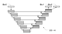
- FIG. 24 is a diagram showing an example of a learning model 22-4 for multi-class classification.
- the learning model 22-4 is a model trained to output correct masks Bc1 and Bc2 in which the infarct region A1 and the bleeding region A2 in the CT image Bc0 are defined, respectively, when the CT image Bc0 is input.
- the learning model 22-4 has a U-Net (U Networks) structure.
- the respective attention pixels Pg10 and Pg20 are calculated using each of the correct masks Bc1 and Bc2, and the gradients M1 (x) and M2 (x) are calculated by the above equations (6) and (7). Is derived.
- a variable CT image Bc2 is generated in the same manner as in the above-described exemplary embodiment. Since the processing after deriving the gradients M1 (x) and M2 (x) is the same as that of the above-described exemplary embodiment, detailed description thereof will be omitted here.
- the technique of the present disclosure is not limited to this, although the gradient M (x) is used. Gradient M (x) may not be used as long as the variation in the output of the learning model deviating from the target value is applied to at least one pixel constituting the CT image Bc0.
- the disease is infarction, but the technique of the present disclosure is not limited to this, and the disease may be bleeding or the like, for example.
- a CT image is used as the learning image of the present disclosure, but the technique of the present disclosure is not limited to this, and the learning image of the present disclosure is, for example, a PET image. It may be an ultrasonic image and another medical image such as an MRI image.
- the MRI image may be any of a T1 image, a T2 image, and a diffusion-weighted image.
- a brain image is used as a medical image, but the present invention is not limited to this.
- the present disclosure can also be applied to discriminate disease areas, areas of interest, etc. included in medical images of the chest, abdomen, whole body, limbs, etc. of the human body.
- the learning device 1 includes a learning image generating device, but the technique of the present disclosure is not limited to this, and the learning image generating device may not be included. ..
- the learning device 1 shall include the teacher data acquisition unit 21, so that the teacher data acquisition unit 21 acquires the second teacher data including the variable learning image generated by the external learning generation device. It should be.
- the learning models 22-2 and 22-4 have a U-Net structure, but the technique of the present disclosure is not limited to this.
- a full-layer convolutional network (FCN) other than U-Net may be used.
- FCN full-layer convolutional network
- various processes such as an image acquisition unit 20, a teacher data acquisition unit 21, a learning model 22, a variation learning image generation unit 23, a learning unit 24, and a display control unit 25 are executed.
- various processors processors shown below can be used.
- the various processors include a CPU, which is a general-purpose processor that executes software (program) and functions as various processing units, and a circuit after manufacturing an FPGA (Field Programmable Gate Array) or the like.
- Dedicated electricity which is a processor with a circuit configuration specially designed to execute specific processing such as programmable logic device (PLD), ASIC (Application Specific Integrated Circuit), which is a processor whose configuration can be changed. Circuits and the like are included.
- PLD programmable logic device
- ASIC Application Specific Integrated Circuit
- One processing unit may be composed of one of these various processors, or a combination of two or more processors of the same type or different types (for example, a combination of a plurality of FPGAs or a combination of a CPU and an FPGA). ) May be configured. Further, a plurality of processing units may be configured by one processor.
- one processor is configured by combining one or more CPUs and software. There is a form in which this processor functions as a plurality of processing units.
- SoC System On Chip
- the various processing units are configured by using one or more of the various processors as a hardware structure.
- circuitry in which circuit elements such as semiconductor elements are combined can be used.
Landscapes
- Engineering & Computer Science (AREA)
- Theoretical Computer Science (AREA)
- Health & Medical Sciences (AREA)
- Computer Vision & Pattern Recognition (AREA)
- Physics & Mathematics (AREA)
- General Physics & Mathematics (AREA)
- General Health & Medical Sciences (AREA)
- Medical Informatics (AREA)
- Evolutionary Computation (AREA)
- Multimedia (AREA)
- Databases & Information Systems (AREA)
- Artificial Intelligence (AREA)
- Computing Systems (AREA)
- Software Systems (AREA)
- Life Sciences & Earth Sciences (AREA)
- Radiology & Medical Imaging (AREA)
- Nuclear Medicine, Radiotherapy & Molecular Imaging (AREA)
- Quality & Reliability (AREA)
- Molecular Biology (AREA)
- Biomedical Technology (AREA)
- Heart & Thoracic Surgery (AREA)
- Biophysics (AREA)
- High Energy & Nuclear Physics (AREA)
- Optics & Photonics (AREA)
- Pathology (AREA)
- Biodiversity & Conservation Biology (AREA)
- Surgery (AREA)
- Animal Behavior & Ethology (AREA)
- Public Health (AREA)
- Veterinary Medicine (AREA)
- Image Analysis (AREA)
- Apparatus For Radiation Diagnosis (AREA)
- Image Processing (AREA)
Abstract
Un dispositif de génération d'image d'apprentissage comprend : une unité d'acquisition d'image pour acquérir une image d'apprentissage ; et une unité de génération d'image d'apprentissage de fluctuation pour, lorsque l'image d'apprentissage acquise par l'unité d'acquisition d'image est entrée dans un modèle, générer une image d'apprentissage de fluctuation par ajout d'une variation de la sortie du modèle d'une valeur cible à la valeur de pixel d'au moins un pixel qui constitue l'image d'apprentissage.
Priority Applications (2)
| Application Number | Priority Date | Filing Date | Title |
|---|---|---|---|
| JP2021535326A JP7321271B2 (ja) | 2019-07-26 | 2020-07-27 | 学習用画像生成装置、方法及びプログラム、並びに学習方法、装置及びプログラム |
| US17/584,289 US20220148294A1 (en) | 2019-07-26 | 2022-01-25 | Learning image generation device, learning image generation method, learning image generation program, learning method, learning device, and learning program |
Applications Claiming Priority (2)
| Application Number | Priority Date | Filing Date | Title |
|---|---|---|---|
| JP2019138235 | 2019-07-26 | ||
| JP2019-138235 | 2019-07-26 |
Related Child Applications (1)
| Application Number | Title | Priority Date | Filing Date |
|---|---|---|---|
| US17/584,289 Continuation US20220148294A1 (en) | 2019-07-26 | 2022-01-25 | Learning image generation device, learning image generation method, learning image generation program, learning method, learning device, and learning program |
Publications (1)
| Publication Number | Publication Date |
|---|---|
| WO2021020339A1 true WO2021020339A1 (fr) | 2021-02-04 |
Family
ID=74230436
Family Applications (1)
| Application Number | Title | Priority Date | Filing Date |
|---|---|---|---|
| PCT/JP2020/028685 WO2021020339A1 (fr) | 2019-07-26 | 2020-07-27 | Dispositif, procédé et programme de génération d'image d'apprentissage, et procédé, dispositif et programme d'apprentissage |
Country Status (3)
| Country | Link |
|---|---|
| US (1) | US20220148294A1 (fr) |
| JP (1) | JP7321271B2 (fr) |
| WO (1) | WO2021020339A1 (fr) |
Families Citing this family (1)
| Publication number | Priority date | Publication date | Assignee | Title |
|---|---|---|---|---|
| CN117173497B (zh) * | 2023-11-02 | 2024-02-27 | 腾讯科技(深圳)有限公司 | 一种图像生成方法、装置、电子设备及存储介质 |
Citations (3)
| Publication number | Priority date | Publication date | Assignee | Title |
|---|---|---|---|---|
| WO2007029467A1 (fr) * | 2005-09-05 | 2007-03-15 | Konica Minolta Medical & Graphic, Inc. | Procédé et dispositif de traitement d'image |
| JP2018206382A (ja) * | 2017-06-01 | 2018-12-27 | 株式会社東芝 | 画像処理システム及び医用情報処理システム |
| US20190197358A1 (en) * | 2017-12-21 | 2019-06-27 | International Business Machines Corporation | Generative Adversarial Network Medical Image Generation for Training of a Classifier |
Family Cites Families (3)
| Publication number | Priority date | Publication date | Assignee | Title |
|---|---|---|---|---|
| US10565686B2 (en) | 2017-06-12 | 2020-02-18 | Nvidia Corporation | Systems and methods for training neural networks for regression without ground truth training samples |
| JP6772112B2 (ja) | 2017-07-31 | 2020-10-21 | 株式会社日立製作所 | 医用撮像装置及び医用画像処理方法 |
| JP2021010970A (ja) | 2019-07-05 | 2021-02-04 | 京セラドキュメントソリューションズ株式会社 | ロボットシステム及びロボット制御方法 |
-
2020
- 2020-07-27 WO PCT/JP2020/028685 patent/WO2021020339A1/fr active Application Filing
- 2020-07-27 JP JP2021535326A patent/JP7321271B2/ja active Active
-
2022
- 2022-01-25 US US17/584,289 patent/US20220148294A1/en active Pending
Patent Citations (3)
| Publication number | Priority date | Publication date | Assignee | Title |
|---|---|---|---|---|
| WO2007029467A1 (fr) * | 2005-09-05 | 2007-03-15 | Konica Minolta Medical & Graphic, Inc. | Procédé et dispositif de traitement d'image |
| JP2018206382A (ja) * | 2017-06-01 | 2018-12-27 | 株式会社東芝 | 画像処理システム及び医用情報処理システム |
| US20190197358A1 (en) * | 2017-12-21 | 2019-06-27 | International Business Machines Corporation | Generative Adversarial Network Medical Image Generation for Training of a Classifier |
Also Published As
| Publication number | Publication date |
|---|---|
| JPWO2021020339A1 (fr) | 2021-02-04 |
| US20220148294A1 (en) | 2022-05-12 |
| JP7321271B2 (ja) | 2023-08-04 |
Similar Documents
| Publication | Publication Date | Title |
|---|---|---|
| US11069056B2 (en) | Multi-modal computer-aided diagnosis systems and methods for prostate cancer | |
| US9687199B2 (en) | Medical imaging system providing disease prognosis | |
| JP7366583B2 (ja) | 医用情報処理装置、方法及びプログラム | |
| JP7018856B2 (ja) | 医用画像処理装置、方法およびプログラム | |
| JP7129870B2 (ja) | 疾患領域を判別する判別器の学習装置、方法及びプログラム、疾患領域を判別する判別器、並びに疾患領域判別装置及びプログラム | |
| US11893729B2 (en) | Multi-modal computer-aided diagnosis systems and methods for prostate cancer | |
| CN113424222A (zh) | 用于使用条件生成对抗网络提供中风病灶分割的系统和方法 | |
| KR102067412B1 (ko) | 치매 평가 방법 및 이를 이용한 장치 | |
| JP7339270B2 (ja) | 医用画像処理装置、方法およびプログラム | |
| Yerukalareddy et al. | Brain tumor classification based on mr images using GAN as a pre-trained model | |
| WO2021020339A1 (fr) | Dispositif, procédé et programme de génération d'image d'apprentissage, et procédé, dispositif et programme d'apprentissage | |
| Segars et al. | Population of 100 realistic, patient-based computerized breast phantoms for multi-modality imaging research | |
| US11460528B2 (en) | MRI reconstruction with image domain optimization | |
| Solanki et al. | Brain MRI image classification using image mining algorithms | |
| JP2020068881A (ja) | 情報処理装置、情報処理方法、及びプログラム | |
| JP7334256B2 (ja) | 画像処理装置、方法およびプログラム、学習装置、方法およびプログラム、並びに導出モデル | |
| WO2020262571A1 (fr) | Dispositif, procédé et programme de génération d'image d'apprentissage, et procédé, dispositif et programme d'apprentissage | |
| WO2021070527A1 (fr) | Dispositif de traitement d'image, procédé et programme | |
| Dar et al. | Deep Learning Models for Detection and Diagnosis of Alzheimer's Disease | |
| JP7121191B2 (ja) | 構造物分離装置、方法およびプログラム、学習装置、方法およびプログラム、並びに学習済みモデル | |
| Devi et al. | Effect of situational and instrumental distortions on the classification of brain MR images | |
| JP2021105960A (ja) | 医用情報処理装置 | |
| WO2022153670A1 (fr) | Dispositif, procédé et programme de traitement d'image, et dispositif, procédé et programme d'apprentissage | |
| JP7342120B2 (ja) | 学習装置、方法およびプログラム、クラス分類装置、方法およびプログラム、並びに学習済みモデル | |
| Sarwar et al. | Development of the Tumor Diagnosis Application for Medical Practitioners using Transfer Learning |
Legal Events
| Date | Code | Title | Description |
|---|---|---|---|
| 121 | Ep: the epo has been informed by wipo that ep was designated in this application |
Ref document number: 20848046 Country of ref document: EP Kind code of ref document: A1 |
|
| ENP | Entry into the national phase |
Ref document number: 2021535326 Country of ref document: JP Kind code of ref document: A |
|
| NENP | Non-entry into the national phase |
Ref country code: DE |
|
| 122 | Ep: pct application non-entry in european phase |
Ref document number: 20848046 Country of ref document: EP Kind code of ref document: A1 |