WO2021020339A1 - Learning image generation device, method, and program, and learning method, device, and program - Google Patents
Learning image generation device, method, and program, and learning method, device, and program Download PDFInfo
- Publication number
- WO2021020339A1 WO2021020339A1 PCT/JP2020/028685 JP2020028685W WO2021020339A1 WO 2021020339 A1 WO2021020339 A1 WO 2021020339A1 JP 2020028685 W JP2020028685 W JP 2020028685W WO 2021020339 A1 WO2021020339 A1 WO 2021020339A1
- Authority
- WO
- WIPO (PCT)
- Prior art keywords
- learning
- image
- teacher data
- model
- variation
- Prior art date
Links
Images


Classifications
-
- G—PHYSICS
- G06—COMPUTING; CALCULATING OR COUNTING
- G06V—IMAGE OR VIDEO RECOGNITION OR UNDERSTANDING
- G06V10/00—Arrangements for image or video recognition or understanding
- G06V10/70—Arrangements for image or video recognition or understanding using pattern recognition or machine learning
- G06V10/82—Arrangements for image or video recognition or understanding using pattern recognition or machine learning using neural networks
-
- G—PHYSICS
- G06—COMPUTING; CALCULATING OR COUNTING
- G06V—IMAGE OR VIDEO RECOGNITION OR UNDERSTANDING
- G06V10/00—Arrangements for image or video recognition or understanding
- G06V10/70—Arrangements for image or video recognition or understanding using pattern recognition or machine learning
- G06V10/77—Processing image or video features in feature spaces; using data integration or data reduction, e.g. principal component analysis [PCA] or independent component analysis [ICA] or self-organising maps [SOM]; Blind source separation
- G06V10/774—Generating sets of training patterns; Bootstrap methods, e.g. bagging or boosting
- G06V10/7747—Organisation of the process, e.g. bagging or boosting
-
- A—HUMAN NECESSITIES
- A61—MEDICAL OR VETERINARY SCIENCE; HYGIENE
- A61B—DIAGNOSIS; SURGERY; IDENTIFICATION
- A61B6/00—Apparatus for radiation diagnosis, e.g. combined with radiation therapy equipment
- A61B6/02—Devices for diagnosis sequentially in different planes; Stereoscopic radiation diagnosis
- A61B6/03—Computerised tomographs
-
- G—PHYSICS
- G06—COMPUTING; CALCULATING OR COUNTING
- G06T—IMAGE DATA PROCESSING OR GENERATION, IN GENERAL
- G06T7/00—Image analysis
- G06T7/0002—Inspection of images, e.g. flaw detection
- G06T7/0012—Biomedical image inspection
-
- G—PHYSICS
- G06—COMPUTING; CALCULATING OR COUNTING
- G06T—IMAGE DATA PROCESSING OR GENERATION, IN GENERAL
- G06T7/00—Image analysis
- G06T7/0002—Inspection of images, e.g. flaw detection
- G06T7/0012—Biomedical image inspection
- G06T7/0014—Biomedical image inspection using an image reference approach
-
- G—PHYSICS
- G06—COMPUTING; CALCULATING OR COUNTING
- G06T—IMAGE DATA PROCESSING OR GENERATION, IN GENERAL
- G06T7/00—Image analysis
- G06T7/10—Segmentation; Edge detection
- G06T7/11—Region-based segmentation
-
- G—PHYSICS
- G06—COMPUTING; CALCULATING OR COUNTING
- G06V—IMAGE OR VIDEO RECOGNITION OR UNDERSTANDING
- G06V10/00—Arrangements for image or video recognition or understanding
- G06V10/40—Extraction of image or video features
- G06V10/44—Local feature extraction by analysis of parts of the pattern, e.g. by detecting edges, contours, loops, corners, strokes or intersections; Connectivity analysis, e.g. of connected components
- G06V10/443—Local feature extraction by analysis of parts of the pattern, e.g. by detecting edges, contours, loops, corners, strokes or intersections; Connectivity analysis, e.g. of connected components by matching or filtering
- G06V10/449—Biologically inspired filters, e.g. difference of Gaussians [DoG] or Gabor filters
- G06V10/451—Biologically inspired filters, e.g. difference of Gaussians [DoG] or Gabor filters with interaction between the filter responses, e.g. cortical complex cells
- G06V10/454—Integrating the filters into a hierarchical structure, e.g. convolutional neural networks [CNN]
-
- G—PHYSICS
- G06—COMPUTING; CALCULATING OR COUNTING
- G06V—IMAGE OR VIDEO RECOGNITION OR UNDERSTANDING
- G06V10/00—Arrangements for image or video recognition or understanding
- G06V10/70—Arrangements for image or video recognition or understanding using pattern recognition or machine learning
- G06V10/74—Image or video pattern matching; Proximity measures in feature spaces
- G06V10/75—Organisation of the matching processes, e.g. simultaneous or sequential comparisons of image or video features; Coarse-fine approaches, e.g. multi-scale approaches; using context analysis; Selection of dictionaries
- G06V10/751—Comparing pixel values or logical combinations thereof, or feature values having positional relevance, e.g. template matching
-
- G—PHYSICS
- G06—COMPUTING; CALCULATING OR COUNTING
- G06V—IMAGE OR VIDEO RECOGNITION OR UNDERSTANDING
- G06V10/00—Arrangements for image or video recognition or understanding
- G06V10/70—Arrangements for image or video recognition or understanding using pattern recognition or machine learning
- G06V10/77—Processing image or video features in feature spaces; using data integration or data reduction, e.g. principal component analysis [PCA] or independent component analysis [ICA] or self-organising maps [SOM]; Blind source separation
- G06V10/778—Active pattern-learning, e.g. online learning of image or video features
- G06V10/7784—Active pattern-learning, e.g. online learning of image or video features based on feedback from supervisors
-
- G—PHYSICS
- G06—COMPUTING; CALCULATING OR COUNTING
- G06T—IMAGE DATA PROCESSING OR GENERATION, IN GENERAL
- G06T2207/00—Indexing scheme for image analysis or image enhancement
- G06T2207/10—Image acquisition modality
- G06T2207/10072—Tomographic images
-
- G—PHYSICS
- G06—COMPUTING; CALCULATING OR COUNTING
- G06T—IMAGE DATA PROCESSING OR GENERATION, IN GENERAL
- G06T2207/00—Indexing scheme for image analysis or image enhancement
- G06T2207/10—Image acquisition modality
- G06T2207/10072—Tomographic images
- G06T2207/10081—Computed x-ray tomography [CT]
-
- G—PHYSICS
- G06—COMPUTING; CALCULATING OR COUNTING
- G06T—IMAGE DATA PROCESSING OR GENERATION, IN GENERAL
- G06T2207/00—Indexing scheme for image analysis or image enhancement
- G06T2207/20—Special algorithmic details
- G06T2207/20016—Hierarchical, coarse-to-fine, multiscale or multiresolution image processing; Pyramid transform
-
- G—PHYSICS
- G06—COMPUTING; CALCULATING OR COUNTING
- G06T—IMAGE DATA PROCESSING OR GENERATION, IN GENERAL
- G06T2207/00—Indexing scheme for image analysis or image enhancement
- G06T2207/20—Special algorithmic details
- G06T2207/20081—Training; Learning
-
- G—PHYSICS
- G06—COMPUTING; CALCULATING OR COUNTING
- G06T—IMAGE DATA PROCESSING OR GENERATION, IN GENERAL
- G06T2207/00—Indexing scheme for image analysis or image enhancement
- G06T2207/20—Special algorithmic details
- G06T2207/20084—Artificial neural networks [ANN]
-
- G—PHYSICS
- G06—COMPUTING; CALCULATING OR COUNTING
- G06T—IMAGE DATA PROCESSING OR GENERATION, IN GENERAL
- G06T2207/00—Indexing scheme for image analysis or image enhancement
- G06T2207/30—Subject of image; Context of image processing
- G06T2207/30004—Biomedical image processing
- G06T2207/30016—Brain
-
- G—PHYSICS
- G06—COMPUTING; CALCULATING OR COUNTING
- G06V—IMAGE OR VIDEO RECOGNITION OR UNDERSTANDING
- G06V2201/00—Indexing scheme relating to image or video recognition or understanding
- G06V2201/03—Recognition of patterns in medical or anatomical images
Definitions
- the present disclosure relates to a learning image generator, a method and a program, and a learning method, a device and a program.
- Japanese Unexamined Patent Publication No. 2019-28650 discloses an image identification device that acquires an input image based on the sensor value of the image pickup device and identifies the input image based on the acquired sensor value by using a classifier having a conversion unit. .. This image identification device can obtain an image suitable for identification by learning the conversion unit based on the learning image based on the sensor value of the image pickup device and the correct answer data given to the learning image, and has high accuracy. Image identification can be realized.
- the image to be input is, for example, a brain image of a brain that has developed a stroke such as subarachnoid hemorrhage, intracerebral hemorrhage, and cerebral infarction
- the diseased area such as the infarcted area and the bleeding area to be segmented is , Shape, size, location of onset, etc. are indefinite.
- the pixel value of the diseased area in the brain image changes depending on the elapsed time from the onset of the disease. Therefore, there are various cases in the brain image, and it is difficult to prepare a learning image that can cover all the various cases. Further, when a learning image that can cover all various cases cannot be prepared, it is difficult to stably operate the model for an unknown image in which the learning image does not exist.
- the present disclosure provides a learning image generation device, a method and a program, and a learning method, a device and a program capable of training a model so that the model can operate stably using a limited number of learning images.
- the first aspect of the present disclosure is an image generation device for learning, in which an image acquisition unit that acquires a learning image and a learning image acquired by the image acquisition unit are input to the model, and the model is output.
- a variation learning image generator that generates a variation learning image by adding variations that deviate from the target value to the pixel values of at least one pixel constituting the learning image.
- the learning image is a brain image and the output of the model is 0 or more and less than 0.5, it is determined that there is no cerebral infarction, and when it is 0.5 or more and 1 or less, it is determined that there is a cerebral infarction.
- a model classification discrimination model
- the learning image is an image with an infarct. Since this image is an image with an infarction, “1” determined to have the highest possibility of having an infarction is the “target value” of the present disclosure.
- the “variation away from the target value” is a value at which the output of the model is farther from “1” and is 0.5 or more and less than 0.6.
- the learning image is an image without infarction. Since this image is an image without infarction, “0” determined to have the highest possibility of no infarction is the “target value” of the present disclosure. Therefore, the “variation away from the target value” is a value at which the output of the model is farther from “0” and is greater than 0.3 and less than 0.5.
- the learning image is a brain image and the model is output for each pixel constituting the learning image
- the model output is 0 or more and less than 0.5
- a model segmentation discrimination model in which the pixel does not belong to the cerebral infarction region and is determined to belong to the cerebral infarction region when 0.5 or more and 1 or less is used.
- this pixel is a pixel belonging to the infarcted region. Since this pixel belongs to the infarcted region, “1” determined to be most likely to belong to the infarcted region is the “target value” of the present disclosure.
- the "variation away from the target value” is a value at which the output of the model is farther from “1” and is 0.5 or more and less than 0.6.
- this pixel is a pixel that does not belong to the infarct region. Since this pixel does not belong to the infarct region, “0” determined to be most likely not to belong to the infarct region is the “target value” of the present disclosure. Therefore, the “variation away from the target value” is a value at which the output of the model is farther from “0” and is greater than 0.3 and less than 0.5.
- the variation learning image generation unit acquires the gradient of the output value with respect to the pixel value of each pixel constituting the learning image, and uses the acquired gradient. Fluctuations may be added.
- a third aspect of the present disclosure includes, in the above aspect, a teacher data acquisition unit that acquires teacher data in which a learning image and a correct answer learning image in which a correct answer region is defined in the learning image are combined, and varies.
- the learning image generation unit determines the pixel of interest using the correct learning image of the teacher data acquired by the teacher data acquisition unit, acquires the gradient of the output value of the determined pixel of interest, and obtains the acquired gradient. May be used to add variation.
- the variation learning image generation unit may determine the pixels in the learning image corresponding to the pixels belonging to the correct answer region as the pixels of interest.
- the variation learning image generation unit may determine the pixels in the learning image corresponding to the pixels belonging to the area other than the correct answer region as the pixels of interest. ..
- the variation learning image generation unit determines the pixels in the learning image corresponding to the pixels belonging to the center of gravity of the correct answer region as the pixels of interest. You may.
- the variation learning image generation unit has a plurality of output units in which the model classifies the input learning image into a plurality of classes including one or more correct answer classes.
- the gradient of the output value output from the output unit classified into the correct answer class may be acquired.
- the eighth aspect of the present disclosure is a learning image generation method, in which, when a learning image is acquired and the acquired learning image is input to the model, the output of the model deviates from the target value.
- a variable learning image is generated by adding it to the pixel value of at least one pixel constituting the learning image.
- a ninth aspect of the present disclosure is a learning image generation program, in which an image acquisition unit that acquires a learning image and a learning image acquired by the image acquisition unit are input to the model, and the model is output.
- the computer functions as a variation learning image generation unit that generates a variation learning image by adding a variation that deviates from the target value to the pixel value of at least one pixel constituting the learning image.
- a learning image generator comprising a memory for storing instructions to be executed by a processor and a processor configured to execute the stored instructions. Fluctuation learning is performed by adding a variation in which the output of the model deviates from the target value to the pixel value of at least one pixel constituting the learning image when the acquired image is acquired and the acquired learning image is input to the model. Execute the process to generate the image for use.
- the tenth aspect of the present disclosure is a learning method, in which one or more first teacher data in which a learning image and correct answer information in the learning image are paired, and a learning image are input to a model.
- one or more variation learning images and one or more variation learning images generated by adding fluctuations in which the output of the model deviates from the target value to the pixel values of at least one pixel constituting the learning image, respectively.
- the model is trained using one or more second teacher data in combination with the correct answer information in the learning image before the change.
- the correct answer information may be a correct answer learning image in which a correct answer region is defined in the learning image.
- the model is trained using the plurality of first teacher data in the first learning, and the plurality of first learnings are performed in the second and subsequent learnings. At least one of the teacher data, the first teacher data, may be replaced with the second teacher data to train the model.
- the model is trained using the plurality of first teacher data in the first learning, and at least one first in the second and subsequent learnings. 2 Teacher data may be added to train the model.
- At least one of the second teacher data and the number of the second teacher data to be used is randomly selected for each learning in the second and subsequent learnings. May be set to.
- At least one of the number of the second teacher data and the number of the second teacher data to be used in the second and subsequent learnings may be set in advance in the twelfth or thirteenth aspect.
- the model may be trained using only the plurality of first teacher data at least once in the second and subsequent learnings.
- the seventeenth aspect of the present disclosure is a learning device, in which one or more first teacher data in which a learning image and correct answer information in the learning image are paired, and a learning image are input to a model.
- one or more variation learning images and one or more variation learning images generated by adding fluctuations in which the output of the model deviates from the target value to the pixel values of at least one pixel constituting the learning image, respectively.
- the teacher data acquisition unit that acquires one or more second teacher data that is a combination of the correct answer information in the learning image before the change, and one or more first teacher data and one or more acquired by the teacher data acquisition unit. Includes a learning unit that trains a model using the second teacher data of.
- a learning apparatus comprising a memory for storing instructions to be executed by a processor and a processor configured to execute the stored instructions, wherein the processor is a learning image.
- the eighteenth aspect of the present disclosure is a learning device, and the learning unit can train the model by the learning method in the tenth to sixteenth aspects.
- the nineteenth aspect of the present disclosure is a learning program in which one or more first teacher data in which a learning image and correct answer information in the learning image are paired, and a learning image are input to a model.
- one or more variation learning images and one or more variation learning images generated by adding fluctuations in which the output of the model deviates from the target value to the pixel values of at least one pixel constituting the learning image, respectively.
- the teacher data acquisition unit that acquires one or more second teacher data that is a combination of the correct answer information in the learning image before the change, and one or more first teacher data and one or more acquired by the teacher data acquisition unit.
- the computer is made to function as a learning unit for learning a model using the second teacher data of.
- the correct answer information may be a correct answer learning image in which a correct answer region is defined in the learning image.
- the learning image generator, method and program of the present disclosure, and the learning method, device and program use limited learning images to train a model so that they can operate stably. Can be done.
- a flowchart showing a process of generating a fluctuating CT image A diagram for explaining the second teacher data, which is a combination of a variable CT image and correct answer information.
- Diagram to explain the learning model The figure for demonstrating the learning method using the 1st teacher data and the 2nd teacher data in 2nd exemplary embodiment.
- Flowchart showing the processing performed during learning The figure for demonstrating the learning method using the 1st teacher data and the 2nd teacher data in a 3rd exemplary embodiment.
- the figure for demonstrating the learning method using the 1st teacher data and the 2nd teacher data in a 4th exemplary embodiment.
- the figure for demonstrating the first teacher data which combined the CT image and the correct CT image.
- a flowchart showing a process of generating a fluctuating CT image The figure for demonstrating the 2nd teacher data which combined the variation CT image and the correct answer CT image.
- FIG. 1 is a hardware configuration diagram showing an outline of a diagnosis support system to which a learning image generation device and a learning device according to the first exemplary embodiment of the present disclosure are applied.
- the learning device 1 in the diagnosis support system, the learning device 1, the three-dimensional image capturing device 2, and the image storage server 3 according to this exemplary embodiment are connected via the network 4 in a communicable state.
- the learning device 1 includes a learning model and a learning image generation device according to this exemplary embodiment.
- the three-dimensional imaging device 2 is a device that generates a three-dimensional image representing the site by photographing the site to be diagnosed of the subject, and specifically, a CT (Computed Tomography) device, an MRI ( Magnetic Resonance Imaging) equipment, PET (Positron Emission Tomography) equipment, and the like.
- the medical image generated by the three-dimensional image capturing device 2 is transmitted to the image storage server 3 and stored.
- the diagnosis target site of the patient who is the subject is the brain, and the three-dimensional imaging device 2 is a CT device. Then, in the CT apparatus, a three-dimensional CT image Bc0 including the brain of the subject is generated.
- the image storage server 3 is a computer that stores and manages various data, and is equipped with a large-capacity external storage device and database management software.
- the image storage server 3 communicates with another device via a wired or wireless network 4 to send and receive image data and the like.
- various data including image data of CT images generated by the three-dimensional image capturing device 2 are acquired via a network and stored in a recording medium such as a large-capacity external storage device for management.
- the storage format of the image data and the communication between the devices via the network 4 are based on a protocol such as DICOM (Digital Imaging and Communication in Medicine).
- DICOM Digital Imaging and Communication in Medicine
- the image storage server 3 also stores and manages the first teacher data D (described later) including the CT image Bc0 which is a learning image for learning the learning model 22 described later. doing.
- the learning device 1 including the learning image generation device and the learning model of the present exemplary embodiment is a computer in which the learning image generation program and the learning program of the present disclosure are installed.
- the computer may be a workstation or personal computer directly operated by the diagnosing doctor, or a server computer connected to them via a network.
- the learning image generation program and the learning program are recorded and distributed on a recording medium such as a DVD (Digital Versatile Disc) or a CD-ROM (Compact Disc Read Only Memory), and are installed on a computer from the recording medium.
- a recording medium such as a DVD (Digital Versatile Disc) or a CD-ROM (Compact Disc Read Only Memory)
- it is stored in a storage device of a server computer connected to a network or in a network storage in a state of being accessible from the outside, and is downloaded and installed in a computer used by a doctor upon request.
- FIG. 2 is a diagram showing a schematic configuration of a learning device 1 which is an exemplary embodiment of the present disclosure realized by installing a learning image generation program and a learning program on a computer.
- the learning device 1 includes a CPU (Central Processing Unit) 11, a memory 12, and a storage 13 as a standard workstation configuration. Further, the learning device 1 is connected to a display unit 14 including a liquid crystal display and the like, and an input unit 15 including a keyboard and a mouse.
- the input unit 15 receives various setting inputs by the user. By using the touch panel, the display unit 14 and the input unit 15 may be used in combination.
- the storage 13 includes a hard disk drive, an SSD (Solid State Drive), and the like.
- the storage 13 stores the first teacher data D including the CT image Bc0, which is a learning image for learning the learning model 22, acquired from the image storage server 3 via the network 4, and the information necessary for processing. Various information including is stored.
- the learning image generation program and the learning program are stored in the memory 12.
- the learning image generation program defines an image acquisition process for acquiring a learning image and an image generation process for variable learning as processes to be executed by the CPU 11.
- the variation learning image generation process when the acquired learning image is input to the learning model 22, the variation that the output of the learning model 22 deviates from the target value is the pixel value of at least one pixel constituting the learning image.
- An image for variable learning is generated by adding to.
- one or more first teacher data in which a learning image and a correct answer learning image in which a correct answer region is defined in the learning image are combined, and a learning image.
- Teacher data acquisition processing to acquire one or more second teacher data in combination with the correct answer learning image in which the correct answer region is defined in the learning image before fluctuation in each of the fluctuation learning images, the acquired one or more
- a training process for training a model using the first teacher data and one or more second teacher data a training image, or a target image to be discriminated is input, the discriminant result in the input image is output.
- the discrimination process to be performed, and the display control process for displaying the learning image, the variation learning image, the discrimination result, and the like on the display unit 14 are defined.
- the computer has the image acquisition unit 20, the teacher data acquisition unit 21, the learning model 22, the variation learning image generation unit 23, the learning unit 24, and the display control unit 25.
- the image acquisition unit 20 and the variation learning image generation unit 23 constitute the learning image generation device of this exemplary embodiment.
- the display control unit 25 causes the display unit 14 to display the CT image Bc0 acquired by the image acquisition unit 20, the variable CT image Bc2 described later, the discrimination result, and the like.
- the image acquisition unit 20 acquires the CT image Bc0 from the image storage server 3 via an interface (not shown) connected to the network.
- FIG. 3 is a diagram for explaining the first teacher data F in which the CT image Bc0 and the correct answer information J0 are combined.
- the CT image Bc0 shown in FIG. 3 is a learning image for learning the learning model 22 described later.
- the CT image Bc0 is a three-dimensional image, but here, for the sake of explanation, a two-dimensional tomographic image on one tomographic plane of the CT image Bc0 will be used.
- the image acquisition unit 20 may acquire the CT image Bc0 from the storage 13.
- the image acquisition unit 20 acquires CT images Bc0 of a large number of subjects for learning the learning model 22 described later.
- the teacher data acquisition unit 21 acquires the first teacher data D from the image storage server 3 via an interface (not shown) connected to the network.
- the first teacher data D is data in which the CT image Bc0 and the information indicating “with infarction” or “without infarction” as the correct answer information J0 in the CT image Bc0 are combined.
- the correct answer information J0 of "with infarction” or “without infarction” may be manually input by the user from the input unit 15.
- the discrimination result based on the output value S (x) of the learning model 22 with respect to the entire CT image Bc0 x is "there is an infarcted region" (Table 1). (See), the CT image Bc0 may be an image of "with infarction".
- the learning model 22 determines the presence or absence of a diseased region in the CT image Bc0. That is, it is a model for discriminating the classification of CT image Bc0 (whether or not there is a disease region).
- the disease area is defined as an infarct area as an example.
- the learning model 22 is a model in which a plurality of processing layers are hierarchically connected and deep learning is performed.
- FIG. 4 is a diagram showing an example of the learning model 22.
- the learning model 22 corresponds to the model of the present disclosure.
- the learning model 22 includes an input unit L including three input layers, a first processing unit L2 including four processing layers, a second processing unit L3 including four processing layers, and one output. It is configured to have an output unit L4 including a layer.
- Each input layer, processing layer, and output layer are connected as shown in FIG.
- the first processing unit L2 and the second processing unit L3 use the data set of the CT image Bc0 of a large number of brains including the infarcted region and the correct answer information which is the discrimination result in the CT image Bc0 as teacher data. It is learned to output an output value S (x) indicating a determination result of having an infarcted region or not having an infarcted region for the entire input CT image Bc0 x.
- the correct answer information is information on whether or not there is an infarcted region in the entire CT image Bc0 x.
- an output value S (x) indicating a determination result of having an infarcted region or not having an infarcted region in the entire CT image Bc0 x is output from the output layer of the output unit L4.
- the output value S (x) output by the output unit L4 is a value indicating a determination result of whether or not there is an infarcted region for the entire CT image Bc0 x.
- Table 1 below shows an example of the output value S (x) and the discrimination result by the learning model 22.
- the output value S (x) of the learning model 22 is 0 or more and less than 0.5, it is determined that there is no infarct region, and when it is 0.5 or more and 1 or less, it is determined that there is an infarction. That is, for example, when the CT image Bc0 is input to the learning model 22, if the output value S (x) of the learning model 22 is 0.6, the CT image Bc0 has an infarcted region. Further, when the CT image Bc0 is input to the learning model 22, if the output value S (x) of the learning model 22 is 0.3, the CT image Bc0 has no infarcted region.
- the variation learning image generation unit 23 adds a variation in which the output of the learning model 22 deviates from the target value to the pixel values of at least one pixel constituting the CT image Bc0.
- a variable CT image Bc2 is generated. For example, when the output value S (x) of the learning model 22 is 0.6 for the CT image Bc0 before the fluctuation, it is determined that the CT image Bc0 has an infarcted region. Since this CT image Bc0 is an image with an infarcted region, “1”, which is an output value S (x) determined to have the highest possibility of having an infarcted region, is the “target value”.
- the “variation away from the target value” is a value at which the output value S (x) of the learning model 22 is farther from “1” (lower than “1”), and is 0.5 or more and less than 0.6. It is a variation added to the pixel value so that it becomes a value.
- the CT image Bc0 is an image without an infarcted region. Since this CT image Bc0 is an image without infarction, “0”, which is an output value S (x) determined to have the highest possibility of having no infarction region, is the “target value”.
- the "fluctuation away from the target value” is a value at which the output value S (x) of the learning model 22 is farther from "0", and is a pixel value so as to be a value larger than 0.3 and less than 0.5. It is a fluctuation added to.
- the variation learning image generation unit 23 has a gradient M (x) of the output value S (x) of the learning model 22 with respect to the entire CT image Bc0 x when the CT image Bc0 is first input to the learning model 22.
- the gradient M (x) of the output value S (x) of the learning model 22 with respect to the entire CT image Bc0 x is derived by the following equation (1).
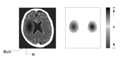
- FIG. 5 is a diagram for explaining the gradient M (x).
- the left figure of FIG. 5 is an example of the CT image Bc0, and the right figure is a diagram in which the values of the gradient M (x) in the CT image Bc0 shown in the left figure are plotted.
- the left figure of FIG. 5 there is a black region on the left side of the image as compared with the right side. This black area shows the findings of cerebral infarction R.
- the area shown by the diagonal line on the left side that is, the gradient M (x) on the side of the area where the cerebral infarction R is found is a negative value, and the area shown in color other than the diagonal line on the right side. That is, the gradient M (x) on the region side where there is no finding of cerebral infarction is a positive value. Further, as the color becomes darker, the absolute value of the gradient M (x) increases.
- the output value S (x) of the learning model 22 increases as the pixel value decreases. .. That is, as the pixel value becomes smaller in the area indicated by the diagonal line on the left side, the area becomes blacker and the output increases. In other words, it is more like a case of cerebral infarction.
- the output value S (x) of the learning model 22 increases as the pixel value increases. That is, in the colored region other than the shaded area on the right side, the larger the pixel value, the whiter the region becomes, and when the left and right regions are compared, the region side where the cerebral infarction R is found becomes relatively blacker, so that the output increases. In other words, it is more like a case of cerebral infarction.
- a variable CT image Bc2 is generated by adding variations to the pixel values of the pixels constituting the CT image Bc0 according to the following equation (2). ..
- xa x-k x M (x) ... (2)
- the constant is k> 0.
- xa indicates the entire variation CT image Bc2 after the entire CT image Bc0 x is varied.
- k ⁇ M (x) represents the entire gradient image shown in the right figure of FIG.
- the variation learning image generation unit 23 subtracts the entire gradient image k ⁇ M (x) shown in the right figure of FIG. 5 from the entire CT image Bc0 x shown in the left figure of FIG. 5, thereby causing the CT image Bc0.
- the pixel value of the pixels constituting the above is changed.
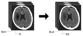
- FIG. 6 is a diagram for explaining the variation CT image Bc2 generated by adding variation to the CT image Bc0.
- the variation learning image generation unit 23 subtracts the entire gradient image k ⁇ M (x) from the entire CT image Bc0 x, as shown in FIG. 6, the region where the cerebral infarction R is found in the CT image Bc0.
- the pixel value is added and the output decreases. Therefore, in the variable CT image Bc2, the black color of the region R2 corresponding to the cerebral infarction R is weakened, which makes it less likely to be a case of cerebral infarction. Further, in the region on the CT image Bc0 opposite to the side where the cerebral infarction R is found, the pixel value is deducted and the output is increased. Therefore, in the variable CT image Bc2, the region corresponding to the side opposite to the cerebral infarction R becomes more black, which makes it more like a case of cerebral infarction.
- the learning model 22 by adding a variation away from the "target value" to the entire CT image Bc0 x, the learning model 22 generates a variable CT image Bc2 in which it is difficult for the learning model 22 to correctly recognize the infarct region as compared with the CT image Bc0 before the variation. be able to.
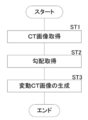
- FIG. 7 is a flowchart showing a process of generating the variable CT image Bc2.
- the image acquisition unit 20 acquires the CT image Bc0 (step ST1).
- the variation learning image generation unit 23 acquires the gradient M (x) of the output value S (x) of the learning model 22 with respect to the entire CT image Bc0 x when the CT image Bc0 is input to the learning model 22. (Step ST2).
- the variation learning image generation unit 23 generates a variation CT image Bc2 by adding a variation away from the “target value” to the entire CT image Bc0 x (step ST3), and a series of processes. Ends the processing of.
- the learning image generation device of this exemplary embodiment composed of the image acquisition unit 20 and the variation learning image generation unit 23, the learning image generation method of this exemplary embodiment, and the learning image of this exemplary embodiment.
- the generation program by adding a variation away from the "target value" to the entire CT image Bc0 x, it is difficult for the learning model 22 to correctly recognize the infarcted region as compared with the CT image Bc0 before the variation.
- Bc2 can be generated. Further, by changing the value of k in the above formula (2), it is possible to generate a plurality of variable CT images Bc2 having different pixel values of the pixels constituting the CT image Bc0.
- variable CT image Bc2 which is a CT image other than the limited CT image Bc0
- the learning model 22 can be trained so that it can operate stably.
- a predetermined constant value may be used, or the value may be randomly changed and used. Further, as will be described later, when the learning model 22 is trained, it may be changed according to the progress of learning. Further, an upper limit value may be set for the value of k in the above formula (2). This makes it possible to prevent the variable CT image Bc2 from becoming an abnormal image. In this case, the upper limit value can be set according to, for example, a possible value of the pixel value.
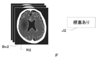
- FIG. 8 is a diagram for explaining the second teacher data F in which the variable CT image Bc2 and the correct answer information J2 are combined.
- the second teacher data F is data in which the fluctuation CT image Bc2 and the information indicating “with infarction” or “without infarction” are combined as the correct answer information J2 in the CT image Bc0 before the fluctuation. is there.
- the correct answer information J2 of "with infarction” or "without infarction” may be manually input by the user from the input unit 15.
- the discrimination result based on the output value S (x) of the learning model 22 with respect to the entire CT image Bc0 x before the change is "there is an infarcted area".
- the fluctuating CT image Bc2 in which the CT image Bc0 is fluctuated may be used as the “with infarction” image.
- FIG. 9 is a diagram for explaining a learning method of the learning model.
- the learning model 22 corresponds to the model of the present disclosure.
- the learning unit 24 inputs the first teacher data D, that is, the CT image Bc0 and the correct answer information J0 into the learning model 22, so that the learning model 22 learns the presence or absence of the infarcted region in the CT image Bc0. ..
- the learning unit 24 inputs the second teacher data F, that is, the variable CT image Bc2 and the correct answer information J2 into the learning model 22, so that the learning model 22 learns the presence or absence of the infarcted region in the variable CT image Bc2.
- the learning model 22 is trained so that the presence or absence of the infarcted region in the variable CT image Bc2 is output.
- n teacher data are trained by the learning model 22 in order.
- the learning model 22 is made to learn the n teacher data again in order for the second time, and the same teacher data is used for a predetermined number of times to repeat the learning model 22. Is being trained.
- FIG. 10 is a diagram for explaining a learning method using the first teacher data D and the second teacher data F in the second exemplary embodiment.
- the first teacher data D and the second teacher data F are a set of CT image Bc0 or variable CT image Bc2 and correct answer information J0 or correct answer information J2, that is, they are composed of two data.
- the first teacher data D and the second teacher data F are represented by one image for convenience of explanation. It may be expressed in the same manner in the following drawings.
- the learning unit 24 trains the learning model 22 using n first teacher data D1 to Dn at the time of the first learning (1T).
- the learning model 22 is trained by replacing the first teacher data D1 with the second teacher data F1.
- the second teacher data F1 is returned to the first teacher data D1
- the first teacher data D2 is replaced with the second teacher data F2 to train the learning model 22.
- the second teacher data F2 is returned to the first teacher data D2, and the first teacher data D3 is replaced with the second teacher data F3 to train the learning model 22.
- the first teacher data D of one of n first teacher data D1 to Dn is used as the second teacher data for each learning.
- the learning model 22 is trained instead of F.
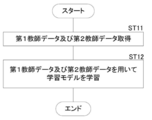
- FIG. 11 is a flowchart showing the processing performed at the time of learning.
- the teacher data acquisition unit 21 acquires the first teacher data D and the second teacher data F from the image storage server 3 and the storage 13 (step ST11).
- the learning unit 24 trains the learning model 22 as described above using the acquired first teacher data D and the second teacher data F (step ST12), and ends a series of processes.
- the correct answer is the variation CT image Bc2 generated by adding the variation in which the output of the model deviates from the "target value" with respect to the entire CT image Bc0 x to the pixels constituting the CT image Bc0.
- the second teacher data F in combination with the information J2 is used for learning.
- the variable CT image Bc2 which is a CT image other than the limited CT image Bc0 Can also be used as a learning image. That is, using the limited CT image Bc0, the learning model 22 can be trained so that it can operate stably even for an unknown CT image other than the CT image Bc0.
- one first teacher data D is replaced with the second teacher data F to train the learning model 22, but the present disclosure shows.
- Technology is not limited to this.
- the two first teacher data D may be replaced with the second teacher data F, or any number of first teacher data D such as three or four may be replaced with the second teacher data F.
- only the predetermined first teacher data D may be replaced with the second teacher data F which is different each time.
- the first teacher data D to be changed to the second teacher data F may be randomly selected.
- the number of the first teacher data D to be changed to the second teacher data F may be randomly determined.
- FIG. 12 is a diagram for explaining a learning method using the first teacher data D and the second teacher data F in the third exemplary embodiment.
- the learning unit 24 trains the learning model 22 using n first teacher data D1 to Dn at the time of the first learning (1T).
- the learning model 22 is trained by replacing the first teacher data D1 with the second teacher data F1.
- the second teacher data F1 is returned to the first teacher data D1
- the first teacher data D2 is returned to the second teacher data F2
- the first teacher data D4 is changed to the second teacher.
- the data F4 is replaced with the first teacher data D5 and the second teacher data F5 to train the learning model 22.
- the second teacher data F2 becomes the first teacher data D2
- the second teacher data F4 becomes the first teacher data D4
- the second teacher data F5 becomes the first teacher data D5.
- the learning model 22 is trained by replacing the first teacher data D1 with the second teacher data F1 and the first teacher data D3 with the second teacher data F3.
- the learning model 22 is trained by replacing the first teacher data D with the second teacher data F each time in the second and subsequent learnings.
- the learning model 22 may be trained by adding the second teacher data F to the n first teacher data Dn each time.
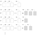
- FIG. 13 is a diagram for explaining a learning method using the first teacher data D and the second teacher data F in the fourth exemplary embodiment.
- the learning unit 24 trains the learning model 22 using n first teacher data D1 to Dn at the time of the first learning (1T).
- the second teacher data F1 is added to train the learning model 22.
- the second teacher data F2 is added to train the learning model 22.
- the second teacher data F3 is added to train the learning model 22.
- a learning model is added by adding one second teacher data F to the n first teacher data D1 to Dn each time. 22 is trained.
- n + 1 learning is completed, the process returns to the first learning (1T), and the above learning is repeated until the set number of learning is completed.
- the learning model 22 is trained by adding one second teacher data F each time in the second and subsequent learnings, but the technique of the present disclosure is not limited to this. .. Two second teacher data Fs may be added, or any number of second teacher data Fs, such as three or four, may be added. Further, the second teacher data F to be added may be randomly selected.
- FIG. 14 is a diagram for explaining a learning method using the first teacher data D and the second teacher data F in the fifth exemplary embodiment.
- the learning unit 24 trains the learning model 22 using n first teacher data D1 to Dn at the time of the first learning (1T).
- the second teacher data F2, the second teacher data F3, and the second teacher data F5 are added to train the learning model 22.
- the second teacher data F4 is added to train the learning model 22.
- the second teacher data F1 and the second teacher data F4 are added to train the learning model 22.
- a random number of second teacher data Fs are added to n first teacher data D1 to Dn each time.
- the learning model 22 is trained until the set number of learnings is completed.
- FIG. 15 is a diagram for explaining a learning method using the first teacher data D and the second teacher data F in the sixth exemplary embodiment.
- the learning unit 24 uses only n first teacher data D1 to Dn at least once in the second and subsequent learnings, and in the seventh learning in this exemplary embodiment.
- the learning model 22 is trained.
- the number of times the learning model 22 is trained using only n first teacher data D1 to Dn is not limited to the seventh time, and may be any time. Further, the learning model 22 may be trained using only the first teacher data D1 to Dn twice, three times, and n times.
- the second teacher data F may use the variable CT image Bc2 in which the value of k in the above formula (2) is changed and varied each time.
- the value of k may be randomly changed each time, or may be a predetermined value.
- the first teacher data D is the teacher data in which the CT image Bc0 and the correct answer information J0 are paired
- the second teacher data F is the variable CT image Bc2 and the correct answer information J2.
- FIG. 16 is a diagram for explaining the first teacher data D-2 in which the CT image Bc0 and the correct CT image Bc1 are combined.
- the first teacher data D includes a CT image Bc0 which is a learning image for learning the learning model 22 and a correct mask Bc1 in which an infarct region A is defined as a correct region in the CT image Bc0. It is the teacher data that is a set of.
- the correct answer mask Bc1 is defined by painting the infarct region A, which is the correct answer region, in white, but the correct answer mask Bc1 is not limited to this.
- the infarct region A may be defined by drawing the boundary of the infarct region A in white without filling the inside of the infarct region A. Further, it may be drawn in a color other than white. Further, the infarct region A may be defined by forming an image in which the inside of the infarct region A and the outside of the infarction region A are composed of pixels having different pixel values.
- the CT image Bc0 of the present exemplary embodiment corresponds to the learning image of the present disclosure
- the correct answer mask Bc1 of the present exemplary embodiment corresponds to the correct answer learning image of the present disclosure.
- the teacher data acquisition unit 21 acquires the first teacher data D-2 from the storage 13. You may try to do it.
- the teacher data acquisition unit 21 acquires the first teacher data D-2 for a large number of subjects for learning the learning model 22-2 described later.
- the variation learning image generation unit 23 applies the CT image Bc0 to the learning model 22-2 (model shown in FIG. 17), which will be described later, with respect to the pixel of interest determined by using the correct mask Bc1.
- the output of the learning model 22-2 is changed to deviate from the target value.
- the learning model 22-2 will be described. The method of determining the pixel of interest will be described in detail later.
- the learning model 22-2 determines the presence or absence of an infarcted region for each pixel constituting the CT image Bc0. That is, it is a model for discriminating the segmentation of the CT image Bc0. Specifically, it is a model learned to output the correct answer mask Bc1 in which the infarct region A in the CT image Bc0 is defined when the CT image Bc0 to be detected in the infarct region A is input.
- the learning model 22-2 has a U-Net (U Networks) structure.
- U-Net is one of the full-layer convolutional networks (FCNs) and is a network specialized in image segmentation.
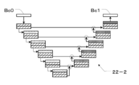
- FIG. 17 is a diagram showing an example of a learning model 22-2 having a U-Net structure.
- the layer indicated by diagonal lines is a convolution layer
- the layer indicated by dots is a pooling layer
- the layer indicated by a grid is an upsampling layer.
- the arrows circled indicate that the image sizes are the same and integrated.
- the downward path (downward arrow in the figure) outputs a feature map in which the amount of data is reduced by the convolution process and the pooling process.
- the upward path (upward arrow in the figure) is output by greatly restoring the size of the feature map by the convolution process and the upsampling process.
- the learning model 22-2 restores the overall position information while preserving the local features by gradually integrating images of the same image size from the deep layers in both paths.
- the learning model 22-2 of this exemplary embodiment can use a known U-Net structure.
- the correct mask Bc1 in which the infarct region A in the CT image Bc0 is defined is obtained from the learning model 22-2. Learning is done so that it is output.
- the correct answer mask Bc1 has an output value of whether each pixel constituting the CT image Bc0 is a pixel belonging to the infarct region or a pixel belonging to a region other than the infarct region.
- the output value of whether a pixel of interest (hereinafter referred to as a pixel of interest) belongs to an infarct region or a pixel other than the infarct region is defined as an output value Ss (x).
- Table 2 below shows an example of the output value Ss (x) and the discrimination result by the learning model 22-2.
- the output value Ss (x) of the learning model 22-2 is 0 or more and less than 0.5, it is determined as a pixel other than the infarct region, and when it is 0.5 or more and 1 or less, it is determined as a pixel in the infarct region. That is, for example, when the CT image Bc0 is input to the learning model 22-2 and the output value Ss (x) of the attention pixel of the learning model 22-2 is 0.6, the attention pixel belongs to the infarct region. It becomes a pixel.
- this attention pixel belongs to a region other than the infarct region. It becomes a pixel.
- the variation learning image generation unit 23 adds a variation in which the output of the attention region of the learning model 22-2 deviates from the target value to the pixel value of the pixel of interest. Generates a variable CT image Bc2. For example, when the output value Ss (x) of the attention pixel of the learning model 22-2 is 0.6 for the CT image Bc0 before the fluctuation, the attention pixel is determined to belong to the infarcted region. Therefore, “1”, which is the output value Ss (x) determined to be the pixel most likely to belong to the infarct region in the pixel of interest, is the “target value”.
- the "fluctuation away from the target value” is a value at which the output value Ss (x) of the pixel of interest of the learning model 22-2 is farther from “1" (lower than “1"), and is 0.5 or more. It is a variation added to the pixel value so that the value is less than 0.6.
- the output value Ss (x) of the attention pixel of the learning model 22-2 is 0.3 for the CT image Bc0 before the fluctuation, the attention pixel is determined to belong to a pixel other than the infarct region.
- the variation learning image generation unit 23 first inputs the CT image Bc0 to the learning model 22-2, and the gradient Ms (x) of the output value Ss (x) of the learning model 22-2 with respect to the pixel of interest s ( x) is acquired.
- the gradient Ms (x) of the output value Ss (x) of the learning model 22-2 with respect to the pixel of interest is derived by the following equation (3).
- a variable CT image Bc2 is generated by adding variations to at least one pixel constituting the CT image Bc0 according to the following equation (4). ..
- x indicates the entire CT image Bc0
- xa indicates the entire variation CT image Bc2 after the CT image Bc0 is changed.
- k ⁇ Ms (x) represents the entire gradient image as in the right figure of FIG.
- the variation learning image generation unit 23 gives variation to at least one pixel constituting the CT image Bc0 by subtracting the entire gradient image k ⁇ Ms (x) from the entire CT image Bc0 x. Image Bc2 is generated.
- the variation learning image generation unit 23 first detects the pixel to which the center of gravity G of the infarct region A defined in the correct answer mask Bc1 belongs.
- FIG. 18 is a diagram for explaining a pixel of interest.
- the image generation unit 23 for fluctuation learning derives the center of gravity G of the infarct region A.
- the center of gravity G can be derived by a known method.
- the variation learning image generation unit 23 detects the pixel Pg to which the center of gravity G of the infarct region A belongs.
- the pixels whose detected pixels Pg correspond to the CT image Bc0 are determined as the pixels of interest Pgs.
- FIG. 19 is a diagram for explaining the pixel of interest Pgs on the CT image Bc0.
- the variation learning image generation unit 23 determines the pixel on the CT image Bc0 corresponding to the pixel Pg to which the center of gravity G of the infarct region A detected in the correct mask Bc1 belongs as the pixel of interest Pgs. .. Then, as described above, when the CT image Bc0 is input to the learning model 22-2 (the model shown in FIG. 17), the output of the attention pixel Pgs of the learning model 22-2 deviates from the target value. Add. As a result, the variation learning image generation unit 23 generates a variation CT image Bc2 in which variations are added on the CT image Bc0.
- FIG. 20 is a flowchart showing a process of generating a variable CT image Bc2.
- the teacher data acquisition unit 21 acquires the first teacher data D in which the CT image Bc0 and the correct answer mask Bc1 are paired (step ST21).
- the variation learning image generation unit 23 determines the pixels of interest Pgs in the CT image Bc0 (step ST22).
- the variation learning image generation unit 23 acquires the gradient Ms (x) of the output value Ss (x) of the learning model 22-2 with respect to the attention pixel Pgs of the CT image Bc0 (step ST23).
- the variation learning image generation unit 23 generates the variation CT image Bc2 by adding the variation in which the output of the pixel of interest Pgs deviates from the “target value” to the CT image Bc0 (step ST24). Ends a series of processes.
- the learning image generation device of this exemplary embodiment composed of the image acquisition unit 20, the teacher data acquisition unit 21, and the variation learning image generation unit 23, the learning image generation method of this exemplary embodiment, and this example.
- the learning model 22-2 is compared with the CT image Bc0 before the fluctuation by adding the fluctuation that the output of the attention pixel Pgs deviates from the “target value” to the CT image Bc0. Can generate a variable CT image Bc2 that makes it difficult to correctly recognize the infarcted area.
- the variable CT image Bc2 which is a CT image other than the limited CT image Bc0, can also be used as a learning image. Therefore, using the limited CT image Bc0, an unknown CT image other than the CT image Bc0 can be used.
- the learning model 22-2 which will be described later, can be trained so that the image can be operated stably.
- the number of pixels of interest Pgs is one, but the technique of the present disclosure is not limited to this, and a plurality of pixels of interest Pgs may be used.
- the pixel Pg detected by the correct answer mask Bc1 is not limited to the pixel to which the center of gravity G belongs, and can be arbitrarily detected from the pixel belonging to the infarct region A.
- the plurality of attention pixels Pgs1, Pgs2, ... On the CT image Bc0 corresponding to the plurality of detected pixels Pg, the output values Ss1 (x), Ss2 (x), ..
- the variation learning image generation unit 23 constitutes the CT image Bc0 by subtracting the entire gradient image k ⁇ (Ms1 (x) + Ms2 (x) + ...) from the entire CT image Bc0 x. Generates a variation CT image Bc2 in which the output of the pixels of interest Pgs1, Pgs2, ... Is given a variation that deviates from the "target value". In this way, by adding a variation to the CT image Bc0 in which the output of the plurality of attention pixels Pgs1, Pgs2, ... of the CT image Bc0 deviates from the "target value", the learning model is compared with the CT image Bc0 before the variation. 22 can generate a variable CT image Bc2 in which it is difficult to correctly recognize the infarcted area.
- the pixel Pg detected by the correct mask Bc1 is detected from the pixel belonging to the infarct region A, but the technique of the present disclosure is not limited to this, and the pixel belonging to the infarct region A and the infarct region It may be detected from both the pixels belonging to the region other than A. Further, it may be detected only from the pixels belonging to the region other than the infarct region A.
- FIG. 21 is a diagram for explaining the second teacher data F-2, which is a combination of a variable CT image and a correct CT image.
- the second teacher data F-2 is a teacher in which the variable CT image Bc2 and the correct answer mask Bc1 in which the infarct region A is defined in the CT image Bc0 before the fluctuation of the variable CT image Bc2 are combined. It is data.
- the second teacher data F-2 is a combination of the variable CT image Bc2 and the correct mask Bc1 in which the infarct region A is defined in the CT image Bc0 before the fluctuation, but the variable CT image Bc2 And the correct answer mask Bc3 in which the infarct region A is newly defined in the variable CT image Bc2 may be combined.
- the variable CT image Bc2 is changed so that the discrimination result based on the output value Ss (x) of the learning model 22-2 for the pixel of interest does not change in the CT image Bc0 before the fluctuation, so that the answer is correct.
- the mask Bc1 and the correct mask Bc3 in which the infarct region A is newly defined in the variable CT image Bc2 are the same correct masks.
- FIG. 22 is a diagram for explaining the learning method of the learning model 22-2.
- the learning model 22-2 corresponds to the model of the present disclosure.
- the learning unit 24 inputs the first teacher data D-2, that is, the CT image Bc0 and the correct mask Bc1 into the learning model 22-2, so that the learning model 22-2 has an infarction in the CT image Bc0. Train area A.
- the learning model 22-2 is trained so that the region matching the correct mask Bc1 is output as the infarct region A.
- the learning unit 24 inputs the second teacher data F-2, that is, the variable CT image Bc2 and the correct answer mask Bc1 into the learning model 22-2, so that the learning model 22-2 is provided with the infarct region A in the variable CT image Bc2. Let them learn. As a result, when the variable CT image Bc2 is input, the learning model 22-2 is trained so that the region matching the correct mask Bc1 is output as the infarct region A.
- the learning model 22 and the learning model 22-2 are single-class models having one output unit, but the technique of the present disclosure is not limited to this, and there are a plurality of learning models. It may be a multi-class model having an output unit.
- FIG. 23 is a diagram showing an example of a learning model 22-3 for multi-class classification.
- the output unit L4 of the learning model 22 shown in FIG. 4 has one output layer
- the learning model 22-3 of the present exemplary embodiment as shown in FIG. 23, the output unit L4 has one output layer. It has three output layers.
- the output values S1 (x) to S3 (x) output from the three output layers include at least one of the convolution layer and the pooling layer, as in the learning model 22 shown in FIG.
- the output value S1 (x) is a value indicating the determination result of whether or not the infarcted region A is present on the CT image Bc0.
- the output value S2 (x) a value representing the determination result of the anatomical site of the infarction identified on the CT image Bc0 is output.
- the output value S3 (x) a value indicating a determination result of whether or not there is a bleeding region on the CT image Bc0 is output.
- the gradients M1 (x) are obtained by the following equations (6) to (8) for the output values S1 (x) to S3 (x) of the input CT image Bc0. ⁇ M3 (x) is derived.
- M1 (x) ⁇ S1 (x) / ⁇ x ... (6)
- M2 (x) ⁇ S2 (x) / ⁇ x ... (7)
- M3 (x) ⁇ S3 (x) / ⁇ x ... (8)
- a variable CT image Bc2 is generated in the same manner as in the above-described exemplary embodiment. Since the processing after deriving the gradients M1 (x) to M3 (x) is the same as that of the first exemplary embodiment, detailed description thereof will be omitted here.
- the learning model of multi-class classification is not limited to the learning model 22-3 shown in FIG.
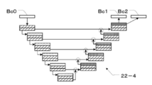
- FIG. 24 is a diagram showing an example of a learning model 22-4 for multi-class classification.
- the learning model 22-4 is a model trained to output correct masks Bc1 and Bc2 in which the infarct region A1 and the bleeding region A2 in the CT image Bc0 are defined, respectively, when the CT image Bc0 is input.
- the learning model 22-4 has a U-Net (U Networks) structure.
- the respective attention pixels Pg10 and Pg20 are calculated using each of the correct masks Bc1 and Bc2, and the gradients M1 (x) and M2 (x) are calculated by the above equations (6) and (7). Is derived.
- a variable CT image Bc2 is generated in the same manner as in the above-described exemplary embodiment. Since the processing after deriving the gradients M1 (x) and M2 (x) is the same as that of the above-described exemplary embodiment, detailed description thereof will be omitted here.
- the technique of the present disclosure is not limited to this, although the gradient M (x) is used. Gradient M (x) may not be used as long as the variation in the output of the learning model deviating from the target value is applied to at least one pixel constituting the CT image Bc0.
- the disease is infarction, but the technique of the present disclosure is not limited to this, and the disease may be bleeding or the like, for example.
- a CT image is used as the learning image of the present disclosure, but the technique of the present disclosure is not limited to this, and the learning image of the present disclosure is, for example, a PET image. It may be an ultrasonic image and another medical image such as an MRI image.
- the MRI image may be any of a T1 image, a T2 image, and a diffusion-weighted image.
- a brain image is used as a medical image, but the present invention is not limited to this.
- the present disclosure can also be applied to discriminate disease areas, areas of interest, etc. included in medical images of the chest, abdomen, whole body, limbs, etc. of the human body.
- the learning device 1 includes a learning image generating device, but the technique of the present disclosure is not limited to this, and the learning image generating device may not be included. ..
- the learning device 1 shall include the teacher data acquisition unit 21, so that the teacher data acquisition unit 21 acquires the second teacher data including the variable learning image generated by the external learning generation device. It should be.
- the learning models 22-2 and 22-4 have a U-Net structure, but the technique of the present disclosure is not limited to this.
- a full-layer convolutional network (FCN) other than U-Net may be used.
- FCN full-layer convolutional network
- various processes such as an image acquisition unit 20, a teacher data acquisition unit 21, a learning model 22, a variation learning image generation unit 23, a learning unit 24, and a display control unit 25 are executed.
- various processors processors shown below can be used.
- the various processors include a CPU, which is a general-purpose processor that executes software (program) and functions as various processing units, and a circuit after manufacturing an FPGA (Field Programmable Gate Array) or the like.
- Dedicated electricity which is a processor with a circuit configuration specially designed to execute specific processing such as programmable logic device (PLD), ASIC (Application Specific Integrated Circuit), which is a processor whose configuration can be changed. Circuits and the like are included.
- PLD programmable logic device
- ASIC Application Specific Integrated Circuit
- One processing unit may be composed of one of these various processors, or a combination of two or more processors of the same type or different types (for example, a combination of a plurality of FPGAs or a combination of a CPU and an FPGA). ) May be configured. Further, a plurality of processing units may be configured by one processor.
- one processor is configured by combining one or more CPUs and software. There is a form in which this processor functions as a plurality of processing units.
- SoC System On Chip
- the various processing units are configured by using one or more of the various processors as a hardware structure.
- circuitry in which circuit elements such as semiconductor elements are combined can be used.
Abstract
A learning image generation device including: an image acquisition unit for acquiring a learning image; and a fluctuation learning image generation unit for, when the learning image acquired by the image acquisition unit is inputted to a model, generating a fluctuation learning image by adding a variation of the output of the model from a target value to the pixel value of at least one pixel that constitutes the learning image.
Description
本開示は、学習用画像生成装置、方法及びプログラム、並びに学習方法、装置及びプログラムに関する。
The present disclosure relates to a learning image generator, a method and a program, and a learning method, a device and a program.
近年、ディープラーニング(深層学習)を用いた機械学習の技術が注目を集めている。ディープラーニングを用いることによって、画像に含まれる物体を検出及び分類したり、画像に含まれる物体の領域をセグメンテーションしたりするモデルを構築できることが知られている。ディープラーニングにおいては、画像識別の精度をより向上させるために様々な技術が開発されている。特開2019-28650号公報には、撮像装置のセンサ値による入力画像を取得し、変換部を有する識別器を用いて、取得されたセンサ値による入力画像を識別する画像識別装置に関する開示がある。この画像識別装置は、撮像装置のセンサ値による学習画像とこの学習画像に付与された正解データとに基づいて変換部を学習させることにより、識別に適した画像を得ることができ、かつ高精度な画像識別を実現できる。
In recent years, machine learning technology using deep learning has been attracting attention. It is known that by using deep learning, it is possible to construct a model for detecting and classifying an object contained in an image and segmenting a region of the object contained in the image. In deep learning, various techniques have been developed to further improve the accuracy of image identification. Japanese Unexamined Patent Publication No. 2019-28650 discloses an image identification device that acquires an input image based on the sensor value of the image pickup device and identifies the input image based on the acquired sensor value by using a classifier having a conversion unit. .. This image identification device can obtain an image suitable for identification by learning the conversion unit based on the learning image based on the sensor value of the image pickup device and the correct answer data given to the learning image, and has high accuracy. Image identification can be realized.
一般的に、ディープラーニングにおいては、多くの学習用画像があるほど、より精度の高い出力結果が得られることが知られている。しかしながら、入力対象となる画像が、例えば、くも膜下出血、脳内出血、及び脳梗塞等の脳卒中を発症した脳の脳画像である場合、セグメンテーションの対象となる梗塞領域及び出血領域等の疾患領域は、形状、大きさ、及び発症箇所等が不定である。また、疾患の発症からの経過時間によって脳画像中の疾患領域の画素値が変化する。そのため、脳画像においては多様な症例が存在することとなり、多様な症例を全てカバーできる程度の学習用画像を用意するのは困難である。また、多様な症例を全てカバーできる程度の学習用画像が用意できない場合には、学習用画像が存在しない未知の画像に対してモデルを安定して動作させることは困難である。
In general, in deep learning, it is known that the more learning images there are, the more accurate the output result can be obtained. However, when the image to be input is, for example, a brain image of a brain that has developed a stroke such as subarachnoid hemorrhage, intracerebral hemorrhage, and cerebral infarction, the diseased area such as the infarcted area and the bleeding area to be segmented is , Shape, size, location of onset, etc. are indefinite. In addition, the pixel value of the diseased area in the brain image changes depending on the elapsed time from the onset of the disease. Therefore, there are various cases in the brain image, and it is difficult to prepare a learning image that can cover all the various cases. Further, when a learning image that can cover all various cases cannot be prepared, it is difficult to stably operate the model for an unknown image in which the learning image does not exist.
本開示は、限られた学習用画像を用いて、安定して動作できるようにモデルを学習させることができる学習用画像生成装置、方法及びプログラム、並びに学習方法、装置及びプログラムを提供する。
The present disclosure provides a learning image generation device, a method and a program, and a learning method, a device and a program capable of training a model so that the model can operate stably using a limited number of learning images.
本開示の第1の態様は、学習用画像生成装置であって、学習用画像を取得する画像取得部と、画像取得部により取得された学習用画像をモデルに入力した場合に、モデルの出力が目標値から離れる変動を、学習用画像を構成する少なくとも1つの画素の画素値に加えることにより変動学習用画像を生成する変動学習用画像生成部と、を含む。
The first aspect of the present disclosure is an image generation device for learning, in which an image acquisition unit that acquires a learning image and a learning image acquired by the image acquisition unit are input to the model, and the model is output. Includes a variation learning image generator that generates a variation learning image by adding variations that deviate from the target value to the pixel values of at least one pixel constituting the learning image.
ここで、例えば、学習用画像が脳画像の場合であって、モデルの出力が0以上0.5未満の場合に脳梗塞なし、0.5以上1以下の場合に脳梗塞ありと判別されるモデル(分類判別モデル)を使用することとする。この場合、変動前の学習用画像について、モデルの出力が0.6の場合には、この学習用画像は梗塞ありの画像となる。この画像は梗塞ありの画像であるため、最も梗塞ありの可能性が高いと判別される「1」が本開示の「目標値」となる。よって「目標値から離れる変動」は、モデルの出力が「1」からより離れる値であって、0.5以上0.6未満の値となる変動である。一方、変動前の学習用画像について、モデルの出力が0.3の場合には、この学習用画像は梗塞なしの画像となる。この画像は梗塞なしの画像であるため、最も梗塞なしの可能性が高いと判別される「0」が本開示の「目標値」となる。よって「目標値から離れる変動」は、モデルの出力が「0」からより離れる値であって、0.3よりも大きく0.5未満の値となる変動である。
Here, for example, when the learning image is a brain image and the output of the model is 0 or more and less than 0.5, it is determined that there is no cerebral infarction, and when it is 0.5 or more and 1 or less, it is determined that there is a cerebral infarction. A model (classification discrimination model) will be used. In this case, when the output of the model is 0.6 for the learning image before the fluctuation, the learning image is an image with an infarct. Since this image is an image with an infarction, “1” determined to have the highest possibility of having an infarction is the “target value” of the present disclosure. Therefore, the "variation away from the target value" is a value at which the output of the model is farther from "1" and is 0.5 or more and less than 0.6. On the other hand, when the output of the model is 0.3 for the learning image before the fluctuation, the learning image is an image without infarction. Since this image is an image without infarction, “0” determined to have the highest possibility of no infarction is the “target value” of the present disclosure. Therefore, the “variation away from the target value” is a value at which the output of the model is farther from “0” and is greater than 0.3 and less than 0.5.
また、例えば、学習用画像が脳画像の場合であって、学習用画像を構成する画素毎にモデルの出力がされるモデル、具体的には、モデルの出力が0以上0.5未満の場合にその画素は脳梗塞領域に属さない、0.5以上1以下の場合に脳梗塞領域に属すると判別されるモデル(セグメンテーション判別モデル)を使用することとする。この場合、変動前の学習用画像を構成する1つの画素について、モデルの出力が0.6の場合には、この画素は梗塞領域に属する画素となる。この画素は梗塞領域に属する画素であるため、最も梗塞領域に属する可能性が高いと判別される「1」が本開示の「目標値」となる。よって「目標値から離れる変動」は、モデルの出力が「1」からより離れる値であって、0.5以上0.6未満の値となる変動である。一方、変動前の学習用画像を構成する1つの画素について、モデルの出力が0.3の場合には、この画素は梗塞領域に属さない画素となる。この画素は梗塞領域に属さない画素であるため、最も梗塞領域に属さない可能性が高いと判別される「0」が本開示の「目標値」となる。よって「目標値から離れる変動」は、モデルの出力が「0」からより離れる値であって、0.3よりも大きく0.5未満の値となる変動である。
Further, for example, when the learning image is a brain image and the model is output for each pixel constituting the learning image, specifically, when the model output is 0 or more and less than 0.5. In addition, a model (segmentation discrimination model) in which the pixel does not belong to the cerebral infarction region and is determined to belong to the cerebral infarction region when 0.5 or more and 1 or less is used. In this case, when the output of the model is 0.6 for one pixel constituting the learning image before the fluctuation, this pixel is a pixel belonging to the infarcted region. Since this pixel belongs to the infarcted region, “1” determined to be most likely to belong to the infarcted region is the “target value” of the present disclosure. Therefore, the "variation away from the target value" is a value at which the output of the model is farther from "1" and is 0.5 or more and less than 0.6. On the other hand, when the output of the model is 0.3 for one pixel constituting the learning image before the fluctuation, this pixel is a pixel that does not belong to the infarct region. Since this pixel does not belong to the infarct region, “0” determined to be most likely not to belong to the infarct region is the “target value” of the present disclosure. Therefore, the “variation away from the target value” is a value at which the output of the model is farther from “0” and is greater than 0.3 and less than 0.5.
本開示の第2の態様は、第1の態様において、変動学習用画像生成部は、学習用画像を構成する各画素の画素値に対する出力値の勾配を取得し、取得した勾配を使用して変動を加えてもよい。
In the second aspect of the present disclosure, in the first aspect, the variation learning image generation unit acquires the gradient of the output value with respect to the pixel value of each pixel constituting the learning image, and uses the acquired gradient. Fluctuations may be added.
本開示の第3の態様は、上記態様において、学習用画像と、学習用画像において正解領域が定義された正解学習用画像とを組にした教師データを取得する教師データ取得部を備え、変動学習用画像生成部は、教師データ取得部により取得された教師データのうちの正解学習用画像を用いて注目画素を決定し、決定した注目画素の出力値の勾配を取得し、取得した勾配を使用して変動を加えてもよい。
A third aspect of the present disclosure includes, in the above aspect, a teacher data acquisition unit that acquires teacher data in which a learning image and a correct answer learning image in which a correct answer region is defined in the learning image are combined, and varies. The learning image generation unit determines the pixel of interest using the correct learning image of the teacher data acquired by the teacher data acquisition unit, acquires the gradient of the output value of the determined pixel of interest, and obtains the acquired gradient. May be used to add variation.
本開示の第4の態様は、上記第3の態様において、変動学習用画像生成部は、正解領域に属する画素に対応する学習用画像における画素を注目画素として決定してもよい。
In the fourth aspect of the present disclosure, in the third aspect described above, the variation learning image generation unit may determine the pixels in the learning image corresponding to the pixels belonging to the correct answer region as the pixels of interest.
本開示の第5の態様は、上記第3又は第4の態様において、変動学習用画像生成部は、正解領域以外に属する画素に対応する学習用画像における画素を注目画素として決定してもよい。
In the fifth aspect of the present disclosure, in the third or fourth aspect, the variation learning image generation unit may determine the pixels in the learning image corresponding to the pixels belonging to the area other than the correct answer region as the pixels of interest. ..
本開示の第6の態様は、上記第3から第5のいずれか1態様において、変動学習用画像生成部は、正解領域の重心に属する画素に対応する学習用画像における画素を注目画素として決定してもよい。
In the sixth aspect of the present disclosure, in any one of the third to fifth aspects, the variation learning image generation unit determines the pixels in the learning image corresponding to the pixels belonging to the center of gravity of the correct answer region as the pixels of interest. You may.
本開示の第7の態様は、上記態様において、変動学習用画像生成部は、モデルが、入力された学習用画像を1以上の正解クラスを含む複数のクラスに分類する複数の出力部を有するモデルであって、正解クラスに分類する出力部から出力される出力値の勾配を取得してもよい。
In the seventh aspect of the present disclosure, in the above aspect, the variation learning image generation unit has a plurality of output units in which the model classifies the input learning image into a plurality of classes including one or more correct answer classes. In the model, the gradient of the output value output from the output unit classified into the correct answer class may be acquired.
本開示の第8の態様は、学習用画像生成方法であって、学習用画像を取得し、取得された学習用画像をモデルに入力した場合に、モデルの出力が目標値から離れる変動を、学習用画像を構成する少なくとも1つの画素の画素値に加えることにより変動学習用画像を生成する。
The eighth aspect of the present disclosure is a learning image generation method, in which, when a learning image is acquired and the acquired learning image is input to the model, the output of the model deviates from the target value. A variable learning image is generated by adding it to the pixel value of at least one pixel constituting the learning image.
本開示の第9の態様は、学習用画像生成プログラムであって、学習用画像を取得する画像取得部と、画像取得部により取得された学習用画像をモデルに入力した場合に、モデルの出力が目標値から離れる変動を、学習用画像を構成する少なくとも1つの画素の画素値に加えることにより変動学習用画像を生成する変動学習用画像生成部として、コンピュータを機能させる。
A ninth aspect of the present disclosure is a learning image generation program, in which an image acquisition unit that acquires a learning image and a learning image acquired by the image acquisition unit are input to the model, and the model is output. The computer functions as a variation learning image generation unit that generates a variation learning image by adding a variation that deviates from the target value to the pixel value of at least one pixel constituting the learning image.
本開示の他の態様は、学習用画像生成装置であって、プロセッサに実行させるための命令を記憶するメモリと、記憶された命令を実行するよう構成されたプロセッサとを備え、プロセッサは、学習用画像を取得し、取得された学習用画像をモデルに入力した場合に、モデルの出力が目標値から離れる変動を、学習用画像を構成する少なくとも1つの画素の画素値に加えることにより変動学習用画像を生成する処理を実行する。
Another aspect of the present disclosure is a learning image generator comprising a memory for storing instructions to be executed by a processor and a processor configured to execute the stored instructions. Fluctuation learning is performed by adding a variation in which the output of the model deviates from the target value to the pixel value of at least one pixel constituting the learning image when the acquired image is acquired and the acquired learning image is input to the model. Execute the process to generate the image for use.
本開示の第10の態様は、学習方法であって、学習用画像と、学習用画像における正解情報とを組にした1以上の第1教師データ、及び、学習用画像をモデルに入力した場合に、モデルの出力が目標値から離れる変動を、学習用画像を構成する少なくとも1つの画素の画素値に加えることにより生成した1以上の変動学習用画像と、1以上の変動学習用画像の各々において変動前の学習用画像における正解情報とを組にした1以上の第2教師データを用いてモデルを学習させる。
The tenth aspect of the present disclosure is a learning method, in which one or more first teacher data in which a learning image and correct answer information in the learning image are paired, and a learning image are input to a model. In addition, one or more variation learning images and one or more variation learning images generated by adding fluctuations in which the output of the model deviates from the target value to the pixel values of at least one pixel constituting the learning image, respectively. In, the model is trained using one or more second teacher data in combination with the correct answer information in the learning image before the change.
本開示の第11の態様は、上記第10の態様において、正解情報は、学習用画像において正解領域が定義された正解学習用画像であってもよい。
In the eleventh aspect of the present disclosure, in the tenth aspect, the correct answer information may be a correct answer learning image in which a correct answer region is defined in the learning image.
本開示の第12の態様は、上記第10又は第11の態様において、1回目の学習において、複数の第1教師データを用いてモデルを学習させ、2回目以降の学習において、複数の第1教師データのうちの少なくとも1つの第1教師データを第2教師データに換えてモデルを学習させてもよい。
In the twelfth aspect of the present disclosure, in the tenth or eleventh aspect, the model is trained using the plurality of first teacher data in the first learning, and the plurality of first learnings are performed in the second and subsequent learnings. At least one of the teacher data, the first teacher data, may be replaced with the second teacher data to train the model.
本開示の第13の態様は、上記第10又は第11の態様において、1回目の学習において、複数の第1教師データを用いてモデルを学習させ、2回目以降の学習において、少なくとも1つの第2教師データを追加してモデルを学習させてもよい。
In the thirteenth aspect of the present disclosure, in the tenth or eleventh aspect, the model is trained using the plurality of first teacher data in the first learning, and at least one first in the second and subsequent learnings. 2 Teacher data may be added to train the model.
本開示の第14の態様は、上記第12又は第13の態様において、2回目以降の学習において、学習の回毎に、使用する第2教師データ及び第2教師データの数の少なくとも一方をランダムに設定してもよい。
In the fourteenth aspect of the present disclosure, in the twelfth or thirteenth aspect, at least one of the second teacher data and the number of the second teacher data to be used is randomly selected for each learning in the second and subsequent learnings. May be set to.
本開示の第15の態様は、上記第12又は第13の態様において、2回目以降の学習において、使用する第2教師データ及び第2教師データの数の少なくとも一方を予め設定してもよい。
In the fifteenth aspect of the present disclosure, at least one of the number of the second teacher data and the number of the second teacher data to be used in the second and subsequent learnings may be set in advance in the twelfth or thirteenth aspect.
本開示の第16の態様は、上記第12から第15の態様において、2回目以降の学習において、少なくとも1回、複数の第1教師データのみを用いてモデルを学習させてもよい。
In the 16th aspect of the present disclosure, in the 12th to 15th aspects described above, the model may be trained using only the plurality of first teacher data at least once in the second and subsequent learnings.
本開示の第17の態様は、学習装置であって、学習用画像と、学習用画像における正解情報とを組にした1以上の第1教師データ、及び、学習用画像をモデルに入力した場合に、モデルの出力が目標値から離れる変動を、学習用画像を構成する少なくとも1つの画素の画素値に加えることにより生成した1以上の変動学習用画像と、1以上の変動学習用画像の各々において変動前の学習用画像における正解情報とを組にした1以上の第2教師データとを取得する教師データ取得部と、教師データ取得部により取得された1以上の第1教師データ及び1以上の第2教師データを用いてモデルを学習させる学習部と、を含む。
The seventeenth aspect of the present disclosure is a learning device, in which one or more first teacher data in which a learning image and correct answer information in the learning image are paired, and a learning image are input to a model. In addition, one or more variation learning images and one or more variation learning images generated by adding fluctuations in which the output of the model deviates from the target value to the pixel values of at least one pixel constituting the learning image, respectively. In the teacher data acquisition unit that acquires one or more second teacher data that is a combination of the correct answer information in the learning image before the change, and one or more first teacher data and one or more acquired by the teacher data acquisition unit. Includes a learning unit that trains a model using the second teacher data of.
本開示の他の態様は、学習装置であって、プロセッサに実行させるための命令を記憶するメモリと、記憶された命令を実行するよう構成されたプロセッサとを備え、プロセッサは、学習用画像と、学習用画像における正解情報とを組にした1以上の第1教師データ、及び、学習用画像をモデルに入力した場合に、モデルの出力が目標値から離れる変動を、学習用画像を構成する少なくとも1つの画素の画素値に加えることにより生成した1以上の変動学習用画像と、1以上の変動学習用画像の各々において変動前の学習用画像における正解情報とを組にした1以上の第2教師データを用いてモデルを学習させる処理を実行する。
Another aspect of the present disclosure is a learning apparatus comprising a memory for storing instructions to be executed by a processor and a processor configured to execute the stored instructions, wherein the processor is a learning image. , One or more first teacher data in combination with the correct answer information in the learning image, and the fluctuation that the output of the model deviates from the target value when the learning image is input to the model, constitutes the learning image. One or more first image in which one or more variation learning images generated by adding to the pixel value of at least one pixel and correct answer information in the learning image before variation in each of one or more variation learning images are paired. 2 Execute the process of training the model using the teacher data.
本開示の第18の態様は、学習装置であって、学習部は、上記第10から第16の態様における学習方法によってモデルを学習させることができる。
The eighteenth aspect of the present disclosure is a learning device, and the learning unit can train the model by the learning method in the tenth to sixteenth aspects.
本開示の第19の態様は、学習プログラムであって、学習用画像と、学習用画像における正解情報とを組にした1以上の第1教師データ、及び、学習用画像をモデルに入力した場合に、モデルの出力が目標値から離れる変動を、学習用画像を構成する少なくとも1つの画素の画素値に加えることにより生成した1以上の変動学習用画像と、1以上の変動学習用画像の各々において変動前の学習用画像における正解情報とを組にした1以上の第2教師データとを取得する教師データ取得部と、教師データ取得部により取得された1以上の第1教師データ及び1以上の第2教師データを用いてモデルを学習させる学習部として、コンピュータを機能させる。
The nineteenth aspect of the present disclosure is a learning program in which one or more first teacher data in which a learning image and correct answer information in the learning image are paired, and a learning image are input to a model. In addition, one or more variation learning images and one or more variation learning images generated by adding fluctuations in which the output of the model deviates from the target value to the pixel values of at least one pixel constituting the learning image, respectively. In the teacher data acquisition unit that acquires one or more second teacher data that is a combination of the correct answer information in the learning image before the change, and one or more first teacher data and one or more acquired by the teacher data acquisition unit. The computer is made to function as a learning unit for learning a model using the second teacher data of.
なお、本開示の学習装置及び学習プログラムにおいては、正解情報が、学習用画像において正解領域が定義された正解学習用画像であってもよい。
In the learning device and the learning program of the present disclosure, the correct answer information may be a correct answer learning image in which a correct answer region is defined in the learning image.
上記態様によれば、本開示の学習用画像生成装置、方法及びプログラム、並びに学習方法、装置及びプログラムは、限られた学習用画像を用いて、安定して動作できるようにモデルを学習させることができる。
According to the above aspect, the learning image generator, method and program of the present disclosure, and the learning method, device and program use limited learning images to train a model so that they can operate stably. Can be done.
以下、図面を参照して本開示の第1の例示的実施形態について説明する。図1は、本開示の第1の例示的実施形態による学習用画像生成装置及び学習装置を適用した、診断支援システムの概要を示すハードウェア構成図である。図1に示すように、診断支援システムでは、本例示的実施形態による学習装置1、3次元画像撮影装置2、及び画像保管サーバ3が、ネットワーク4を経由して通信可能な状態で接続されている。なお、学習装置1には、本例示的実施形態による学習モデル及び学習用画像生成装置が内包される。
Hereinafter, the first exemplary embodiment of the present disclosure will be described with reference to the drawings. FIG. 1 is a hardware configuration diagram showing an outline of a diagnosis support system to which a learning image generation device and a learning device according to the first exemplary embodiment of the present disclosure are applied. As shown in FIG. 1, in the diagnosis support system, the learning device 1, the three-dimensional image capturing device 2, and the image storage server 3 according to this exemplary embodiment are connected via the network 4 in a communicable state. There is. The learning device 1 includes a learning model and a learning image generation device according to this exemplary embodiment.
3次元画像撮影装置2は、被検体の診断対象となる部位を撮影することにより、その部位を表す3次元画像を生成する装置であり、具体的には、CT(Computed Tomography)装置、MRI(Magnetic Resonance Imaging)装置、及びPET(Positron Emission Tomography)装置等である。この3次元画像撮影装置2により生成された医用画像は画像保管サーバ3に送信され、保存される。なお、本例示的実施形態においては、被検体である患者の診断対象部位は脳であり、3次元画像撮影装置2はCT装置である。そして、CT装置において、被検体の脳を含む3次元のCT画像Bc0を生成する。
The three-dimensional imaging device 2 is a device that generates a three-dimensional image representing the site by photographing the site to be diagnosed of the subject, and specifically, a CT (Computed Tomography) device, an MRI ( Magnetic Resonance Imaging) equipment, PET (Positron Emission Tomography) equipment, and the like. The medical image generated by the three-dimensional image capturing device 2 is transmitted to the image storage server 3 and stored. In this exemplary embodiment, the diagnosis target site of the patient who is the subject is the brain, and the three-dimensional imaging device 2 is a CT device. Then, in the CT apparatus, a three-dimensional CT image Bc0 including the brain of the subject is generated.
画像保管サーバ3は、各種データを保存して管理するコンピュータであり、大容量外部記憶装置及びデータベース管理用ソフトウェアを備えている。画像保管サーバ3は、有線あるいは無線のネットワーク4を介して他の装置と通信を行い、画像データ等を送受信する。具体的には3次元画像撮影装置2で生成されたCT画像の画像データを含む各種データをネットワーク経由で取得し、大容量外部記憶装置等の記録媒体に保存して管理する。なお、画像データの格納形式及びネットワーク4経由での各装置間の通信は、DICOM(Digital Imaging and Communication in Medicine)等のプロトコルに基づいている。また、本例示的実施形態においては、画像保管サーバ3は、後述する学習モデル22の学習のための学習用画像となるCT画像Bc0を含む第1教師データD(後述する)も保管して管理している。
The image storage server 3 is a computer that stores and manages various data, and is equipped with a large-capacity external storage device and database management software. The image storage server 3 communicates with another device via a wired or wireless network 4 to send and receive image data and the like. Specifically, various data including image data of CT images generated by the three-dimensional image capturing device 2 are acquired via a network and stored in a recording medium such as a large-capacity external storage device for management. The storage format of the image data and the communication between the devices via the network 4 are based on a protocol such as DICOM (Digital Imaging and Communication in Medicine). Further, in the present exemplary embodiment, the image storage server 3 also stores and manages the first teacher data D (described later) including the CT image Bc0 which is a learning image for learning the learning model 22 described later. doing.
本例示的実施形態の学習用画像生成装置及び学習モデルを含む学習装置1は、1台のコンピュータに、本開示の学習用画像生成プログラム及び学習プログラムをインストールしたものである。コンピュータは、診断を行う医師が直接操作するワークステーション又はパーソナルコンピュータでもよいし、それらとネットワークを介して接続されたサーバコンピュータでもよい。学習用画像生成プログラム及び学習プログラムは、DVD(Digital Versatile Disc)あるいはCD-ROM(Compact Disc Read Only Memory)等の記録媒体に記録されて配布され、その記録媒体からコンピュータにインストールされる。又は、ネットワークに接続されたサーバコンピュータの記憶装置、もしくはネットワークストレージに、外部からアクセス可能な状態で記憶され、要求に応じて医師が使用するコンピュータにダウンロードされ、インストールされる。
The learning device 1 including the learning image generation device and the learning model of the present exemplary embodiment is a computer in which the learning image generation program and the learning program of the present disclosure are installed. The computer may be a workstation or personal computer directly operated by the diagnosing doctor, or a server computer connected to them via a network. The learning image generation program and the learning program are recorded and distributed on a recording medium such as a DVD (Digital Versatile Disc) or a CD-ROM (Compact Disc Read Only Memory), and are installed on a computer from the recording medium. Alternatively, it is stored in a storage device of a server computer connected to a network or in a network storage in a state of being accessible from the outside, and is downloaded and installed in a computer used by a doctor upon request.
図2は、コンピュータに学習用画像生成プログラム及び学習プログラムをインストールすることにより実現される本開示の一例示的実施形態である学習装置1の概略構成を示す図である。図2に示すように、学習装置1は、標準的なワークステーションの構成として、CPU(Central Processing Unit)11、メモリ12及びストレージ13を備えている。また、学習装置1には、液晶ディスプレイ等からなる表示部14、並びにキーボード及びマウス等からなる入力部15が接続されている。入力部15は、ユーザによる種々の設定入力を受け付ける。なお、タッチパネルを用いることによって表示部14と入力部15とを兼用するようにしてもよい。
FIG. 2 is a diagram showing a schematic configuration of a learning device 1 which is an exemplary embodiment of the present disclosure realized by installing a learning image generation program and a learning program on a computer. As shown in FIG. 2, the learning device 1 includes a CPU (Central Processing Unit) 11, a memory 12, and a storage 13 as a standard workstation configuration. Further, the learning device 1 is connected to a display unit 14 including a liquid crystal display and the like, and an input unit 15 including a keyboard and a mouse. The input unit 15 receives various setting inputs by the user. By using the touch panel, the display unit 14 and the input unit 15 may be used in combination.
ストレージ13は、ハードディスクドライブ及びSSD(Solid State Drive)等からなる。ストレージ13には、ネットワーク4を経由して画像保管サーバ3から取得した、学習モデル22の学習のための学習用画像となるCT画像Bc0を含む第1教師データD、及び処理に必要な情報を含む各種情報が記憶されている。
The storage 13 includes a hard disk drive, an SSD (Solid State Drive), and the like. The storage 13 stores the first teacher data D including the CT image Bc0, which is a learning image for learning the learning model 22, acquired from the image storage server 3 via the network 4, and the information necessary for processing. Various information including is stored.
また、メモリ12には、学習用画像生成プログラム及び学習プログラムが記憶されている。学習用画像生成プログラムは、CPU11に実行させる処理として、学習用画像を取得する画像取得処理と、変動学習用画像生成処理とを規定する。変動学習用画像生成処理は、取得された学習用画像を学習モデル22に入力した場合に、学習モデル22の出力が目標値から離れる変動を、学習用画像を構成する少なくとも1つの画素の画素値に加えることにより変動学習用画像を生成する。
Further, the learning image generation program and the learning program are stored in the memory 12. The learning image generation program defines an image acquisition process for acquiring a learning image and an image generation process for variable learning as processes to be executed by the CPU 11. In the variation learning image generation process, when the acquired learning image is input to the learning model 22, the variation that the output of the learning model 22 deviates from the target value is the pixel value of at least one pixel constituting the learning image. An image for variable learning is generated by adding to.
また、学習プログラムは、CPU11に実行させる処理として、学習用画像と、学習用画像において正解領域が定義された正解学習用画像とを組にした1以上の第1教師データ、及び、学習用画像をモデルに入力した場合に、モデルの出力が目標値から離れる変動を、学習用画像を構成する少なくとも1つの画素の画素値に加えることにより生成した1以上の変動学習用画像と、1以上の変動学習用画像の各々において変動前の学習用画像において正解領域が定義された正解学習用画像とを組にした1以上の第2教師データとを取得する教師データ取得処理、取得された1以上の第1教師データ及び1以上の第2教師データを用いてモデルを学習させる学習処理、学習用画像又は判別の対象となる対象画像が入力された場合に、入力された画像における判別結果を出力する判別処理、並びに学習用画像、変動学習用画像、及び判別結果等を表示部14に表示する表示制御処理を規定する。
Further, in the learning program, as a process to be executed by the CPU 11, one or more first teacher data in which a learning image and a correct answer learning image in which a correct answer region is defined in the learning image are combined, and a learning image. Is added to the pixel values of at least one pixel constituting the learning image to generate one or more fluctuation learning images and one or more fluctuations in which the output of the model deviates from the target value when is input to the model. Teacher data acquisition processing to acquire one or more second teacher data in combination with the correct answer learning image in which the correct answer region is defined in the learning image before fluctuation in each of the fluctuation learning images, the acquired one or more When a training process for training a model using the first teacher data and one or more second teacher data, a training image, or a target image to be discriminated is input, the discriminant result in the input image is output. The discrimination process to be performed, and the display control process for displaying the learning image, the variation learning image, the discrimination result, and the like on the display unit 14 are defined.
そして、CPU11がプログラムに従いこれらの処理を実行することで、コンピュータは、画像取得部20、教師データ取得部21、学習モデル22、変動学習用画像生成部23、学習部24、及び表示制御部25として機能する。ここで、画像取得部20及び変動学習用画像生成部23が、本例示的実施形態の学習用画像生成装置を構成する。
Then, when the CPU 11 executes these processes according to the program, the computer has the image acquisition unit 20, the teacher data acquisition unit 21, the learning model 22, the variation learning image generation unit 23, the learning unit 24, and the display control unit 25. Functions as. Here, the image acquisition unit 20 and the variation learning image generation unit 23 constitute the learning image generation device of this exemplary embodiment.
表示制御部25は、画像取得部20が取得したCT画像Bc0、後述する変動CT画像Bc2、及び判別結果等を表示部14に表示させる。
The display control unit 25 causes the display unit 14 to display the CT image Bc0 acquired by the image acquisition unit 20, the variable CT image Bc2 described later, the discrimination result, and the like.
画像取得部20は、ネットワークに接続されたインターフェース(不図示)を介して、画像保管サーバ3から、CT画像Bc0を取得する。図3はCT画像Bc0と正解情報J0とを組にした第1教師データFを説明するための図である。図3に示すCT画像Bc0は、後述する学習モデル22の学習のための学習用画像である。なお、図3において、CT画像Bc0は3次元画像であるが、ここでは説明のため、CT画像Bc0の1つの断層面における2次元の断層画像を用いて説明する。なお、CT画像Bc0が既にストレージ13に記憶されている場合には、画像取得部20は、ストレージ13からCT画像Bc0を取得するようにしてもよい。また、画像取得部20は、後述する学習モデル22の学習のために、多数の被検体についてのCT画像Bc0を取得する。
The image acquisition unit 20 acquires the CT image Bc0 from the image storage server 3 via an interface (not shown) connected to the network. FIG. 3 is a diagram for explaining the first teacher data F in which the CT image Bc0 and the correct answer information J0 are combined. The CT image Bc0 shown in FIG. 3 is a learning image for learning the learning model 22 described later. In FIG. 3, the CT image Bc0 is a three-dimensional image, but here, for the sake of explanation, a two-dimensional tomographic image on one tomographic plane of the CT image Bc0 will be used. If the CT image Bc0 is already stored in the storage 13, the image acquisition unit 20 may acquire the CT image Bc0 from the storage 13. In addition, the image acquisition unit 20 acquires CT images Bc0 of a large number of subjects for learning the learning model 22 described later.
教師データ取得部21は、ネットワークに接続されたインターフェース(不図示)を介して、画像保管サーバ3から、第1教師データDを取得する。第1教師データDは、図3に示すように、CT画像Bc0と、CT画像Bc0における正解情報J0として「梗塞あり」又は「梗塞なし」を示す情報とを組にしたデータである。なお、「梗塞あり」又は「梗塞なし」の正解情報J0は、ユーザが入力部15から手動で入力してもよい。また、CT画像Bc0を学習モデル22に入力した場合に、CT画像Bc0全体xに対する学習モデル22の出力値S(x)の値に基づく判別結果が、「梗塞領域あり」である場合(表1参照)に、そのCT画像Bc0を「梗塞あり」の画像としてもよい。
The teacher data acquisition unit 21 acquires the first teacher data D from the image storage server 3 via an interface (not shown) connected to the network. As shown in FIG. 3, the first teacher data D is data in which the CT image Bc0 and the information indicating “with infarction” or “without infarction” as the correct answer information J0 in the CT image Bc0 are combined. The correct answer information J0 of "with infarction" or "without infarction" may be manually input by the user from the input unit 15. Further, when the CT image Bc0 is input to the learning model 22, the discrimination result based on the output value S (x) of the learning model 22 with respect to the entire CT image Bc0 x is "there is an infarcted region" (Table 1). (See), the CT image Bc0 may be an image of "with infarction".
学習モデル22は、CT画像Bc0における疾病領域の有無を判別する。すなわち、CT画像Bc0の分類(疾患領域があるかないか)を判別するモデルである。本例示的実施形態においては、一例として疾病領域を梗塞領域とする。本例示的実施形態においては、学習モデル22は、複数の処理層が階層的に接続され、深層学習(ディープラーニング)がなされたモデルである。図4は学習モデル22の一例を示す図である。なお、学習モデル22は本開示のモデルに対応する。
The learning model 22 determines the presence or absence of a diseased region in the CT image Bc0. That is, it is a model for discriminating the classification of CT image Bc0 (whether or not there is a disease region). In this exemplary embodiment, the disease area is defined as an infarct area as an example. In the present exemplary embodiment, the learning model 22 is a model in which a plurality of processing layers are hierarchically connected and deep learning is performed. FIG. 4 is a diagram showing an example of the learning model 22. The learning model 22 corresponds to the model of the present disclosure.
学習モデル22は、図4に示すように、3つの入力層を含む入力部L1、4つの処理層を含む第1処理部L2、4つの処理層を含む第2処理部L3、及び1つの出力層を含む出力部L4を有して構成されている。各々の入力層、処理層、及び出力層は、図4のように接続されている。
As shown in FIG. 4, the learning model 22 includes an input unit L including three input layers, a first processing unit L2 including four processing layers, a second processing unit L3 including four processing layers, and one output. It is configured to have an output unit L4 including a layer. Each input layer, processing layer, and output layer are connected as shown in FIG.
本例示的実施形態において、第1処理部L2及び第2処理部L3は、梗塞領域を含む多数の脳のCT画像Bc0と、CT画像Bc0における判別結果である正解情報とのデータセットを教師データとして使用して、入力されたCT画像Bc0全体xについての梗塞領域あり又は梗塞領域なしの判別結果を示す出力値S(x)を出力するように学習がなされている。なお、正解情報は、CT画像Bc0全体xにおいて梗塞領域ありか梗塞領域なしかの情報である。
In this exemplary embodiment, the first processing unit L2 and the second processing unit L3 use the data set of the CT image Bc0 of a large number of brains including the infarcted region and the correct answer information which is the discrimination result in the CT image Bc0 as teacher data. It is learned to output an output value S (x) indicating a determination result of having an infarcted region or not having an infarcted region for the entire input CT image Bc0 x. The correct answer information is information on whether or not there is an infarcted region in the entire CT image Bc0 x.
これにより、第1処理部L2の入力層にCT画像Bc0が入力されると、第1処理部L2及び第2処理部L3の複数の処理層において、前段の処理層から出力された特徴量マップが次段の処理層に順次入力される。次に、CT画像Bc0全体xにおける梗塞領域あり又は梗塞領域なしの判別結果を示す出力値S(x)が出力部L4の出力層から出力される。なお、出力部L4が出力する出力値S(x)は、CT画像Bc0全体xについて梗塞領域ありか梗塞領域なしかの判別結果を示す値である。ここで、下記表1に、学習モデル22による出力値S(x)と判別結果の一例を示す。
As a result, when the CT image Bc0 is input to the input layer of the first processing unit L2, the feature amount map output from the previous processing layer in the plurality of processing layers of the first processing unit L2 and the second processing unit L3. Is sequentially input to the processing layer of the next stage. Next, an output value S (x) indicating a determination result of having an infarcted region or not having an infarcted region in the entire CT image Bc0 x is output from the output layer of the output unit L4. The output value S (x) output by the output unit L4 is a value indicating a determination result of whether or not there is an infarcted region for the entire CT image Bc0 x. Here, Table 1 below shows an example of the output value S (x) and the discrimination result by the learning model 22.

学習モデル22の出力値S(x)が0以上0.5未満の場合に梗塞領域なし、0.5以上1以下の場合に梗塞ありと判別される。すなわち、例えばCT画像Bc0を学習モデル22に入力した際に、学習モデル22の出力値S(x)が0.6の場合には、このCT画像Bc0は梗塞領域ありとなる。また、CT画像Bc0を学習モデル22に入力した際に、学習モデル22の出力値S(x)が0.3の場合には、このCT画像Bc0は梗塞領域なしとなる。
When the output value S (x) of the learning model 22 is 0 or more and less than 0.5, it is determined that there is no infarct region, and when it is 0.5 or more and 1 or less, it is determined that there is an infarction. That is, for example, when the CT image Bc0 is input to the learning model 22, if the output value S (x) of the learning model 22 is 0.6, the CT image Bc0 has an infarcted region. Further, when the CT image Bc0 is input to the learning model 22, if the output value S (x) of the learning model 22 is 0.3, the CT image Bc0 has no infarcted region.
変動学習用画像生成部23は、CT画像Bc0を学習モデル22に入力した場合に、学習モデル22の出力が目標値から離れる変動を、CT画像Bc0を構成する少なくとも1つの画素の画素値に加えることにより変動CT画像Bc2を生成する。例えば、変動前のCT画像Bc0について、学習モデル22の出力値S(x)が0.6の場合には、このCT画像Bc0は梗塞領域ありと判別される。このCT画像Bc0は、梗塞領域ありの画像であるため、最も梗塞領域ありの可能性が高いと判別される出力値S(x)である「1」が「目標値」となる。よって「目標値から離れる変動」は、学習モデル22の出力値S(x)が「1」からより離れる(「1」よりも低下する)値であって、0.5以上0.6未満の値となるように画素値に加えられる変動である。一方、変動前のCT画像Bc0について、学習モデル22の出力値S(x)が0.3の場合には、このCT画像Bc0は梗塞領域なしの画像となる。このCT画像Bc0は梗塞なしの画像であるため、最も梗塞領域なしの可能性が高いと判別される出力値S(x)である「0」が「目標値」となる。よって「目標値から離れる変動」は、学習モデル22の出力値S(x)が「0」からより離れる値であって、0.3よりも大きく0.5未満の値となるように画素値に加えられる変動である。
When the CT image Bc0 is input to the learning model 22, the variation learning image generation unit 23 adds a variation in which the output of the learning model 22 deviates from the target value to the pixel values of at least one pixel constituting the CT image Bc0. As a result, a variable CT image Bc2 is generated. For example, when the output value S (x) of the learning model 22 is 0.6 for the CT image Bc0 before the fluctuation, it is determined that the CT image Bc0 has an infarcted region. Since this CT image Bc0 is an image with an infarcted region, “1”, which is an output value S (x) determined to have the highest possibility of having an infarcted region, is the “target value”. Therefore, the “variation away from the target value” is a value at which the output value S (x) of the learning model 22 is farther from “1” (lower than “1”), and is 0.5 or more and less than 0.6. It is a variation added to the pixel value so that it becomes a value. On the other hand, when the output value S (x) of the learning model 22 is 0.3 for the CT image Bc0 before the fluctuation, the CT image Bc0 is an image without an infarcted region. Since this CT image Bc0 is an image without infarction, “0”, which is an output value S (x) determined to have the highest possibility of having no infarction region, is the “target value”. Therefore, the "fluctuation away from the target value" is a value at which the output value S (x) of the learning model 22 is farther from "0", and is a pixel value so as to be a value larger than 0.3 and less than 0.5. It is a fluctuation added to.
変動学習用画像生成部23は、具体的には、まずCT画像Bc0を学習モデル22に入力した場合の、CT画像Bc0全体xに対する学習モデル22の出力値S(x)の勾配M(x)を取得する。CT画像Bc0全体xに対する学習モデル22の出力値S(x)の勾配M(x)は、下記式(1)により導出する。
Specifically, the variation learning image generation unit 23 has a gradient M (x) of the output value S (x) of the learning model 22 with respect to the entire CT image Bc0 x when the CT image Bc0 is first input to the learning model 22. To get. The gradient M (x) of the output value S (x) of the learning model 22 with respect to the entire CT image Bc0 x is derived by the following equation (1).
M(x)=∂S(x)/∂x・・・(1)
M (x) = ∂S (x) / ∂x ... (1)
図5は、勾配M(x)を説明するための図である。図5の左図は、CT画像Bc0の一例、右図は左図に示すCT画像Bc0における勾配M(x)の値をプロットした図である。なお、図5の左図においては、画像上の左側に右側と比較して黒色の領域が存在する。この黒色の領域は脳梗塞Rの所見を示す。図5の右図に示すように、左側の斜線で示す領域、すなわち脳梗塞Rの所見がある領域側の勾配M(x)はマイナスの値であり、右側の斜線以外の色付きで示す領域、すなわち脳梗塞の所見がない領域側の勾配M(x)はプラスの値である。また、色が濃くなるにつれて勾配M(x)の絶対値が大きくなる。
FIG. 5 is a diagram for explaining the gradient M (x). The left figure of FIG. 5 is an example of the CT image Bc0, and the right figure is a diagram in which the values of the gradient M (x) in the CT image Bc0 shown in the left figure are plotted. In the left figure of FIG. 5, there is a black region on the left side of the image as compared with the right side. This black area shows the findings of cerebral infarction R. As shown in the right figure of FIG. 5, the area shown by the diagonal line on the left side, that is, the gradient M (x) on the side of the area where the cerebral infarction R is found is a negative value, and the area shown in color other than the diagonal line on the right side. That is, the gradient M (x) on the region side where there is no finding of cerebral infarction is a positive value. Further, as the color becomes darker, the absolute value of the gradient M (x) increases.
図5の右図で示す左側の斜線で示す領域に属する画素、つまり脳梗塞Rの所見が有る領域に属する画素については、画素値が小さくなると学習モデル22の出力値S(x)が上昇する。すなわち、左側の斜線で示す領域において画素値が小さくなると領域がより黒くなり、出力が上昇する。つまり、より脳梗塞の症例らしくなる。
For the pixels belonging to the region indicated by the diagonal line on the left side shown in the right figure of FIG. 5, that is, the pixels belonging to the region having the finding of cerebral infarction R, the output value S (x) of the learning model 22 increases as the pixel value decreases. .. That is, as the pixel value becomes smaller in the area indicated by the diagonal line on the left side, the area becomes blacker and the output increases. In other words, it is more like a case of cerebral infarction.
上記に対して、図5の右図で示す右側の斜線以外の色付きで示す領域に属する画素については、画素値が大きくなると学習モデル22の出力値S(x)が上昇する。すなわち、右側の斜線以外の色付きで示す領域において画素値が大きくなると領域がより白くなり、左右比べた場合に脳梗塞Rの所見がある領域側が相対的により黒くなるので、出力が上昇する。つまり、より脳梗塞の症例らしくなる。
On the other hand, for the pixels belonging to the colored area other than the shaded area on the right side shown in the right figure of FIG. 5, the output value S (x) of the learning model 22 increases as the pixel value increases. That is, in the colored region other than the shaded area on the right side, the larger the pixel value, the whiter the region becomes, and when the left and right regions are compared, the region side where the cerebral infarction R is found becomes relatively blacker, so that the output increases. In other words, it is more like a case of cerebral infarction.
このように、勾配M(x)を使用することにより、画素値をどのように変動させた場合に、学習モデル22の出力値S(x)がどのように変動するのかを容易に導出することができる。
In this way, by using the gradient M (x), it is possible to easily derive how the output value S (x) of the learning model 22 fluctuates when the pixel value fluctuates. Can be done.
次に、上記式(1)により導出された勾配M(x)を使用して、下記式(2)によりCT画像Bc0を構成する画素の画素値に変動を加えた変動CT画像Bc2を生成する。
Next, using the gradient M (x) derived from the above equation (1), a variable CT image Bc2 is generated by adding variations to the pixel values of the pixels constituting the CT image Bc0 according to the following equation (2). ..
xa=x-k×M(x)・・・(2)
ただし、k>0の定数とする。
ここで、xaは、CT画像Bc0全体xを変動させた後の変動CT画像Bc2全体を示す。また、k×M(x)は図5の右図で示す勾配画像全体を表す。 xa = x-k x M (x) ... (2)
However, the constant is k> 0.
Here, xa indicates the entire variation CT image Bc2 after the entire CT image Bc0 x is varied. Further, k × M (x) represents the entire gradient image shown in the right figure of FIG.
変動学習用画像生成部23は、図5の左図に示すCT画像Bc0全体xに対して、図5の右図に示す勾配画像全体k×M(x)を減算することにより、CT画像Bc0を構成する画素の画素値に変動を加える。図6はCT画像Bc0に変動を加えて生成した変動CT画像Bc2を説明するための図である。
The variation learning image generation unit 23 subtracts the entire gradient image k × M (x) shown in the right figure of FIG. 5 from the entire CT image Bc0 x shown in the left figure of FIG. 5, thereby causing the CT image Bc0. The pixel value of the pixels constituting the above is changed. FIG. 6 is a diagram for explaining the variation CT image Bc2 generated by adding variation to the CT image Bc0.
変動学習用画像生成部23が、CT画像Bc0全体xに対して、勾配画像全体k×M(x)を減算すると、図6に示すように、CT画像Bc0における脳梗塞Rの所見が有る領域は画素値がプラスされて出力が低下する。このため、変動CT画像Bc2において脳梗塞Rに対応する領域R2は黒色が弱まって、より脳梗塞の症例らしくなくなる。また、CT画像Bc0における脳梗塞Rの所見が有る側と反対側の領域は画素値がマイナスされて出力が上昇する。このため、変動CT画像Bc2において脳梗塞Rとは反対側に対応する領域は黒色が強まって、より脳梗塞の症例らしくなる。
When the variation learning image generation unit 23 subtracts the entire gradient image k × M (x) from the entire CT image Bc0 x, as shown in FIG. 6, the region where the cerebral infarction R is found in the CT image Bc0. The pixel value is added and the output decreases. Therefore, in the variable CT image Bc2, the black color of the region R2 corresponding to the cerebral infarction R is weakened, which makes it less likely to be a case of cerebral infarction. Further, in the region on the CT image Bc0 opposite to the side where the cerebral infarction R is found, the pixel value is deducted and the output is increased. Therefore, in the variable CT image Bc2, the region corresponding to the side opposite to the cerebral infarction R becomes more black, which makes it more like a case of cerebral infarction.
このように、CT画像Bc0全体xに「目標値」から離れる変動を加えることにより、変動前のCT画像Bc0と比較して学習モデル22が梗塞領域を正しく認識し難い変動CT画像Bc2を生成することができる。
In this way, by adding a variation away from the "target value" to the entire CT image Bc0 x, the learning model 22 generates a variable CT image Bc2 in which it is difficult for the learning model 22 to correctly recognize the infarct region as compared with the CT image Bc0 before the variation. be able to.
次いで、本例示的実施形態における変動CT画像Bc2を生成する処理について説明する。図7は変動CT画像Bc2を生成する処理を示すフローチャートである。先ず、画像取得部20が、CT画像Bc0を取得する(ステップST1)。次に、変動学習用画像生成部23が、CT画像Bc0を学習モデル22に入力した場合の、CT画像Bc0全体xに対する学習モデル22の出力値S(x)の勾配M(x)を取得する(ステップST2)。そして、変動学習用画像生成部23が、上述したように、CT画像Bc0全体xに対して、「目標値」から離れる変動を加えることにより変動CT画像Bc2を生成して(ステップST3)、一連の処理を終了する。
Next, the process of generating the variable CT image Bc2 in this exemplary embodiment will be described. FIG. 7 is a flowchart showing a process of generating the variable CT image Bc2. First, the image acquisition unit 20 acquires the CT image Bc0 (step ST1). Next, the variation learning image generation unit 23 acquires the gradient M (x) of the output value S (x) of the learning model 22 with respect to the entire CT image Bc0 x when the CT image Bc0 is input to the learning model 22. (Step ST2). Then, as described above, the variation learning image generation unit 23 generates a variation CT image Bc2 by adding a variation away from the “target value” to the entire CT image Bc0 x (step ST3), and a series of processes. Ends the processing of.
画像取得部20及び変動学習用画像生成部23で構成される本例示的実施形態の学習用画像生成装置、本例示的実施形態の学習用画像生成方法、並びに本例示的実施形態の学習用画像生成プログラムによれば、CT画像Bc0全体xに対して「目標値」から離れる変動を加えることにより、変動前のCT画像Bc0と比較して学習モデル22が梗塞領域を正しく認識し難い変動CT画像Bc2を生成することができる。また、上記式(2)のkの値を替えることにより、CT画像Bc0を構成する画素の画素値が異なる複数の変動CT画像Bc2を生成することができる。これにより、限られたCT画像Bc0以外のCT画像である変動CT画像Bc2も学習用画像として使用することができるので、限られたCT画像Bc0を用いて、CT画像Bc0以外の未知のCT画像に対しても安定して動作できるように学習モデル22を学習させることができる。
The learning image generation device of this exemplary embodiment composed of the image acquisition unit 20 and the variation learning image generation unit 23, the learning image generation method of this exemplary embodiment, and the learning image of this exemplary embodiment. According to the generation program, by adding a variation away from the "target value" to the entire CT image Bc0 x, it is difficult for the learning model 22 to correctly recognize the infarcted region as compared with the CT image Bc0 before the variation. Bc2 can be generated. Further, by changing the value of k in the above formula (2), it is possible to generate a plurality of variable CT images Bc2 having different pixel values of the pixels constituting the CT image Bc0. As a result, the variable CT image Bc2, which is a CT image other than the limited CT image Bc0, can also be used as a learning image. Therefore, using the limited CT image Bc0, an unknown CT image other than the CT image Bc0 can be used. The learning model 22 can be trained so that it can operate stably.
なお、上記式(2)のkの値は、予め設定された一定の値を使用してもよいし、ランダムに値を変化させて使用してもよい。また、後述するように、学習モデル22を学習させる際に、学習の進行に応じて変動させてもよい。また、上記式(2)のkの値に上限値を設けてもよい。これにより、変動CT画像Bc2が異常な画像となるのを防止することができる。この場合、上限値は、例えば、画素値の取り得る値に応じて設定することができる。
As the value of k in the above equation (2), a predetermined constant value may be used, or the value may be randomly changed and used. Further, as will be described later, when the learning model 22 is trained, it may be changed according to the progress of learning. Further, an upper limit value may be set for the value of k in the above formula (2). This makes it possible to prevent the variable CT image Bc2 from becoming an abnormal image. In this case, the upper limit value can be set according to, for example, a possible value of the pixel value.
以上のようにして変動学習用画像生成部23により生成された変動CT画像Bc2は、第2教師データFを構成する画像データとしてストレージ13に記憶される。図8は変動CT画像Bc2と正解情報J2とを組にした第2教師データFを説明するための図である。第2教師データFは、図8に示すように、変動CT画像Bc2と、変動前のCT画像Bc0における正解情報J2として「梗塞あり」又は「梗塞なし」を示す情報とを組にしたデータである。なお、「梗塞あり」又は「梗塞なし」の正解情報J2は、ユーザが入力部15から手動で入力してもよい。また、変動前のCT画像Bc0を学習モデル22に入力した場合に、変動前のCT画像Bc0全体xに対する学習モデル22の出力値S(x)の値に基づく判別結果が「梗塞領域あり」である場合に、そのCT画像Bc0を変動させた変動CT画像Bc2を「梗塞あり」の画像としてもよい。
The variation CT image Bc2 generated by the variation learning image generation unit 23 as described above is stored in the storage 13 as image data constituting the second teacher data F. FIG. 8 is a diagram for explaining the second teacher data F in which the variable CT image Bc2 and the correct answer information J2 are combined. As shown in FIG. 8, the second teacher data F is data in which the fluctuation CT image Bc2 and the information indicating “with infarction” or “without infarction” are combined as the correct answer information J2 in the CT image Bc0 before the fluctuation. is there. The correct answer information J2 of "with infarction" or "without infarction" may be manually input by the user from the input unit 15. Further, when the CT image Bc0 before the change is input to the learning model 22, the discrimination result based on the output value S (x) of the learning model 22 with respect to the entire CT image Bc0 x before the change is "there is an infarcted area". In some cases, the fluctuating CT image Bc2 in which the CT image Bc0 is fluctuated may be used as the “with infarction” image.
次に、図2に戻り、学習部24は、教師データ取得部21により取得された1以上の第1教師データD及び1以上の第2教師データFを用いて学習モデル22を学習させる。図9は学習モデルの学習方法を説明するための図である。なお、本例示的実施形態において学習モデル22は、本開示のモデルに対応する。
Next, returning to FIG. 2, the learning unit 24 trains the learning model 22 using one or more first teacher data D and one or more second teacher data F acquired by the teacher data acquisition unit 21. FIG. 9 is a diagram for explaining a learning method of the learning model. In this exemplary embodiment, the learning model 22 corresponds to the model of the present disclosure.
学習部24は、図9に示すように、第1教師データDすなわちCT画像Bc0及び正解情報J0を学習モデル22に入力することにより、学習モデル22にCT画像Bc0における梗塞領域の有無を学習させる。これにより、CT画像Bc0が入力された場合に、CT画像Bc0における梗塞領域の有無が出力されるように学習モデル22を学習させる。また、学習部24は、第2教師データFすなわち変動CT画像Bc2及び正解情報J2を学習モデル22に入力することにより、学習モデル22に変動CT画像Bc2における梗塞領域の有無を学習させる。これにより、変動CT画像Bc2が入力された場合に、変動CT画像Bc2における梗塞領域の有無が出力されるように学習モデル22を学習させる。
As shown in FIG. 9, the learning unit 24 inputs the first teacher data D, that is, the CT image Bc0 and the correct answer information J0 into the learning model 22, so that the learning model 22 learns the presence or absence of the infarcted region in the CT image Bc0. .. As a result, when the CT image Bc0 is input, the learning model 22 is trained so that the presence or absence of the infarcted region in the CT image Bc0 is output. Further, the learning unit 24 inputs the second teacher data F, that is, the variable CT image Bc2 and the correct answer information J2 into the learning model 22, so that the learning model 22 learns the presence or absence of the infarcted region in the variable CT image Bc2. As a result, when the variable CT image Bc2 is input, the learning model 22 is trained so that the presence or absence of the infarcted region in the variable CT image Bc2 is output.
次に、1以上の第1教師データD及び1以上の第2教師データFを用いた学習モデル22の学習方法について説明する。一般的に学習モデル22を学習させる場合には、例えばn個の教師データを順に学習モデル22に学習させる。そして、n個の教師データが全て学習されると、2回目として再度n個の教師データを順に学習モデル22に学習させて、予め定められた回数、同じ教師データを使用して繰り返し学習モデル22に学習させることが行われている。
Next, a learning method of the learning model 22 using one or more first teacher data D and one or more second teacher data F will be described. Generally, when the learning model 22 is trained, for example, n teacher data are trained by the learning model 22 in order. Then, when all n teacher data are learned, the learning model 22 is made to learn the n teacher data again in order for the second time, and the same teacher data is used for a predetermined number of times to repeat the learning model 22. Is being trained.
本例示的実施形態においては、n個の第1教師データD1~Dnを用いて学習モデル22を学習させる際に、1回目はn個の第1教師データD1~Dnを用いて学習モデル22を学習させ、2回目以降は、n個の第1教師データD1~Dnのうちの少なくとも1つの第1教師データDを第2教師データFに換えて学習モデル22を学習させる。図10は第2の例示的実施形態における第1教師データD及び第2教師データFを用いた学習方法を説明するための図である。なお、第1教師データD及び第2教師データFは、CT画像Bc0又は変動CT画像Bc2と、正解情報J0又は正解情報J2との組で、すなわち2つのデータで構成されているが、図10において第1教師データD及び第2教師データFは説明の都合上、1枚の画像で表してある。なお、以下の図面においても同様に表すことがある。
In this exemplary embodiment, when the learning model 22 is trained using n first teacher data D1 to Dn, the learning model 22 is first trained using n first teacher data D1 to Dn. From the second time onward, at least one of the n first teacher data D1 to Dn is replaced with the second teacher data F to train the learning model 22. FIG. 10 is a diagram for explaining a learning method using the first teacher data D and the second teacher data F in the second exemplary embodiment. The first teacher data D and the second teacher data F are a set of CT image Bc0 or variable CT image Bc2 and correct answer information J0 or correct answer information J2, that is, they are composed of two data. In the above, the first teacher data D and the second teacher data F are represented by one image for convenience of explanation. It may be expressed in the same manner in the following drawings.
学習部24は、図10に示すように、1回目の学習時(1T)には、n個の第1教師データD1~Dnを用いて学習モデル22を学習させる。2回目の学習時(2T)には、第1教師データD1を第2教師データF1に換えて学習モデル22を学習させる。3回目の学習時(3T)には、第2教師データF1を第1教師データD1に戻して、かつ、第1教師データD2を第2教師データF2に換えて学習モデル22を学習させる。さらに4回目の学習時(4T)には、第2教師データF2を第1教師データD2に戻して、かつ、第1教師データD3を第2教師データF3に換えて学習モデル22を学習させる。
As shown in FIG. 10, the learning unit 24 trains the learning model 22 using n first teacher data D1 to Dn at the time of the first learning (1T). At the time of the second learning (2T), the learning model 22 is trained by replacing the first teacher data D1 with the second teacher data F1. At the time of the third learning (3T), the second teacher data F1 is returned to the first teacher data D1, and the first teacher data D2 is replaced with the second teacher data F2 to train the learning model 22. Further, at the time of the fourth learning (4T), the second teacher data F2 is returned to the first teacher data D2, and the first teacher data D3 is replaced with the second teacher data F3 to train the learning model 22.
このように、第2の例示的実施形態においては、2回目以降の学習において、回毎に、n個の第1教師データD1~Dnのうちの1つの第1教師データDを第2教師データFに換えて学習モデル22を学習させる。n+1回の学習が終了すると、1回目の学習(1T)に戻り、設定された回数の学習が終了するまで上記学習を繰り返し行う。
As described above, in the second exemplary embodiment, in the second and subsequent learnings, the first teacher data D of one of n first teacher data D1 to Dn is used as the second teacher data for each learning. The learning model 22 is trained instead of F. When n + 1 learning is completed, the process returns to the first learning (1T), and the above learning is repeated until the set number of learning is completed.
次いで、第2の例示的実施形態における一連の処理について説明する。図11は学習時に行われる処理を示すフローチャートである。先ず、教師データ取得部21が、画像保管サーバ3及びストレージ13から第1教師データD及び第2教師データFを取得する(ステップST11)。次いで、学習部24が、取得した第1教師データD及び第2教師データFを用いて、学習モデル22を上述のようにして学習させて(ステップST12)、一連の処理を終了する。
Next, a series of processes in the second exemplary embodiment will be described. FIG. 11 is a flowchart showing the processing performed at the time of learning. First, the teacher data acquisition unit 21 acquires the first teacher data D and the second teacher data F from the image storage server 3 and the storage 13 (step ST11). Next, the learning unit 24 trains the learning model 22 as described above using the acquired first teacher data D and the second teacher data F (step ST12), and ends a series of processes.
第2の例示的実施形態においては、CT画像Bc0全体xに対してモデルの出力が「目標値」から離れる変動をCT画像Bc0を構成する画素に加えることにより生成された変動CT画像Bc2と正解情報J2とを組にした第2教師データFを学習に使用する。このように、第1教師データDのみを使用して学習モデル22を学習させるよりも、第2教師データFを使用することにより、限られたCT画像Bc0以外のCT画像である変動CT画像Bc2も学習用画像として使用することができる。すなわち、限られたCT画像Bc0を用いて、CT画像Bc0以外の未知のCT画像に対しても安定して動作できるように学習モデル22を学習させることができる。
In the second exemplary embodiment, the correct answer is the variation CT image Bc2 generated by adding the variation in which the output of the model deviates from the "target value" with respect to the entire CT image Bc0 x to the pixels constituting the CT image Bc0. The second teacher data F in combination with the information J2 is used for learning. In this way, by using the second teacher data F rather than training the learning model 22 using only the first teacher data D, the variable CT image Bc2 which is a CT image other than the limited CT image Bc0 Can also be used as a learning image. That is, using the limited CT image Bc0, the learning model 22 can be trained so that it can operate stably even for an unknown CT image other than the CT image Bc0.
なお、第2の例示的実施形態においては、2回目以降の学習において、回毎に1つの第1教師データDを第2教師データFに換えて学習モデル22を学習させたが、本開示の技術はこれに限られない。2つの第1教師データDを第2教師データFに換えてもよいし、3つ、4つ等、任意の数の第1教師データDを第2教師データFに替えることができる。また、予め定められた第1教師データDのみを回毎に異なる第2教師データFに換えてもよい。また、第2教師データFに変更する第1教師データDはランダムに選択されるようにしてもよい。また、第2教師データFに変更する第1教師データDの個数はランダムに決定されるようにしてもよい。また、第2教師データFに変更する第1教師データD及び第2教師データFに変更する第1教師データDの個数の両方を、ランダムに決定するようにしてもよい。図12は、第3の例示的実施形態における第1教師データD及び第2教師データFを用いた学習方法を説明するための図である。
In the second exemplary embodiment, in the second and subsequent learnings, one first teacher data D is replaced with the second teacher data F to train the learning model 22, but the present disclosure shows. Technology is not limited to this. The two first teacher data D may be replaced with the second teacher data F, or any number of first teacher data D such as three or four may be replaced with the second teacher data F. Further, only the predetermined first teacher data D may be replaced with the second teacher data F which is different each time. Further, the first teacher data D to be changed to the second teacher data F may be randomly selected. Further, the number of the first teacher data D to be changed to the second teacher data F may be randomly determined. Further, both the number of the first teacher data D to be changed to the second teacher data F and the number of the first teacher data D to be changed to the second teacher data F may be randomly determined. FIG. 12 is a diagram for explaining a learning method using the first teacher data D and the second teacher data F in the third exemplary embodiment.
学習部24は、図12に示すように、1回目の学習時(1T)には、n個の第1教師データD1~Dnを用いて学習モデル22を学習させる。2回目の学習時(2T)には、第1教師データD1を第2教師データF1に換えて学習モデル22を学習させる。3回目の学習時(3T)には、第2教師データF1を第1教師データD1に戻して、かつ、第1教師データD2を第2教師データF2に、第1教師データD4を第2教師データF4に、第1教師データD5を第2教師データF5に、それぞれ換えて学習モデル22を学習させる。さらに4回目の学習時(4T)には、第2教師データF2を第1教師データD2に、第2教師データF4を第1教師データD4に、第2教師データF5を第1教師データD5に、それぞれ戻して、かつ、第1教師データD1を第2教師データF1に、第1教師データD3を第2教師データF3に換えて学習モデル22を学習させる。
As shown in FIG. 12, the learning unit 24 trains the learning model 22 using n first teacher data D1 to Dn at the time of the first learning (1T). At the time of the second learning (2T), the learning model 22 is trained by replacing the first teacher data D1 with the second teacher data F1. At the time of the third learning (3T), the second teacher data F1 is returned to the first teacher data D1, the first teacher data D2 is returned to the second teacher data F2, and the first teacher data D4 is changed to the second teacher. The data F4 is replaced with the first teacher data D5 and the second teacher data F5 to train the learning model 22. Further, at the time of the fourth learning (4T), the second teacher data F2 becomes the first teacher data D2, the second teacher data F4 becomes the first teacher data D4, and the second teacher data F5 becomes the first teacher data D5. The learning model 22 is trained by replacing the first teacher data D1 with the second teacher data F1 and the first teacher data D3 with the second teacher data F3.
なお、第2の例示的実施形態及び第3の例示的実施形態においては、2回目以降の学習において、回毎に第1教師データDを第2教師データFに換えて学習モデル22を学習させたが、本開示の技術はこれに限られない。回毎にn個の第1教師データDnに第2教師データFを追加して学習モデル22を学習させてもよい。図13は第4の例示的実施形態における第1教師データD及び第2教師データFを用いた学習方法を説明するための図である。
In the second exemplary embodiment and the third exemplary embodiment, the learning model 22 is trained by replacing the first teacher data D with the second teacher data F each time in the second and subsequent learnings. However, the technique of the present disclosure is not limited to this. The learning model 22 may be trained by adding the second teacher data F to the n first teacher data Dn each time. FIG. 13 is a diagram for explaining a learning method using the first teacher data D and the second teacher data F in the fourth exemplary embodiment.
学習部24は、図13に示すように、1回目の学習時(1T)には、n個の第1教師データD1~Dnを用いて学習モデル22を学習させる。2回目の学習時(2T)には、第2教師データF1を加えて学習モデル22を学習させる。3回目の学習時(3T)には、第2教師データF2を加えて学習モデル22を学習させる。さらに4回目の学習時(4T)には、第2教師データF3を加えて学習モデル22を学習させる。
As shown in FIG. 13, the learning unit 24 trains the learning model 22 using n first teacher data D1 to Dn at the time of the first learning (1T). At the time of the second learning (2T), the second teacher data F1 is added to train the learning model 22. At the time of the third learning (3T), the second teacher data F2 is added to train the learning model 22. Further, at the time of the fourth learning (4T), the second teacher data F3 is added to train the learning model 22.
このように、第4の例示的実施形態においては、2回目以降の学習において、回毎に、n個の第1教師データD1~Dnに、さらに第2教師データFを1つ加えて学習モデル22を学習させる。n+1回の学習が終了すると、1回目の学習(1T)に戻り、設定された回数の学習が終了するまで上記学習を繰り返し行う。
As described above, in the fourth exemplary embodiment, in the second and subsequent learnings, a learning model is added by adding one second teacher data F to the n first teacher data D1 to Dn each time. 22 is trained. When n + 1 learning is completed, the process returns to the first learning (1T), and the above learning is repeated until the set number of learning is completed.
なお、第4の例示的実施形態においては、2回目以降の学習において、回毎に1つの第2教師データF加えて学習モデル22を学習させたが、本開示の技術はこれに限られない。2つの第2教師データFを加えてもよいし、3つ、4つ等、任意の数の第2教師データFを加えることができる。また、加える第2教師データFはランダムに選択されるようにしてもよい。図14は第5の例示的実施形態における第1教師データD及び第2教師データFを用いた学習方法を説明するための図である。
In the fourth exemplary embodiment, the learning model 22 is trained by adding one second teacher data F each time in the second and subsequent learnings, but the technique of the present disclosure is not limited to this. .. Two second teacher data Fs may be added, or any number of second teacher data Fs, such as three or four, may be added. Further, the second teacher data F to be added may be randomly selected. FIG. 14 is a diagram for explaining a learning method using the first teacher data D and the second teacher data F in the fifth exemplary embodiment.
学習部24は、図14に示すように、1回目の学習時(1T)には、n個の第1教師データD1~Dnを用いて学習モデル22を学習させる。2回目の学習時(2T)には、第2教師データF2、第2教師データF3、及び第2教師データF5を加えて学習モデル22を学習させる。3回目の学習時(3T)には、第2教師データF4を加えて学習モデル22を学習させる。さらに4回目の学習時(4T)には、第2教師データF1及び第2教師データF4を加えて学習モデル22を学習させる。
As shown in FIG. 14, the learning unit 24 trains the learning model 22 using n first teacher data D1 to Dn at the time of the first learning (1T). At the time of the second learning (2T), the second teacher data F2, the second teacher data F3, and the second teacher data F5 are added to train the learning model 22. At the time of the third learning (3T), the second teacher data F4 is added to train the learning model 22. Further, at the time of the fourth learning (4T), the second teacher data F1 and the second teacher data F4 are added to train the learning model 22.
このように、第5の例示的実施形態においては、2回目以降の学習において、回毎に、n個の第1教師データD1~Dnに、さらに第2教師データFをランダムの個数加えて、設定された回数の学習が終了するまで学習モデル22を学習させる。
As described above, in the fifth exemplary embodiment, in the second and subsequent learnings, a random number of second teacher data Fs are added to n first teacher data D1 to Dn each time. The learning model 22 is trained until the set number of learnings is completed.
なお、本開示の学習モデル22の学習方法は上記第2~第5の例示的実施形態に示す学習方法に限られない。図15は、第6の例示的実施形態における第1教師データD及び第2教師データFを用いた学習方法を説明するための図である。
The learning method of the learning model 22 of the present disclosure is not limited to the learning method shown in the above-mentioned second to fifth exemplary embodiments. FIG. 15 is a diagram for explaining a learning method using the first teacher data D and the second teacher data F in the sixth exemplary embodiment.
学習部24は、図15に示すように、2回目以降の学習において、少なくとも1回、本例示的実施形態においては7回目の学習において、n個の第1教師データD1~Dnのみを用いて学習モデル22を学習させる。なお、n個の第1教師データD1~Dnのみを用いて学習モデル22を学習させる回は、7回目に限られず何れの回であってもよい。また、2回、3回とn個の第1教師データD1~Dnのみを用いて学習モデル22を学習させてもよい。
As shown in FIG. 15, the learning unit 24 uses only n first teacher data D1 to Dn at least once in the second and subsequent learnings, and in the seventh learning in this exemplary embodiment. The learning model 22 is trained. The number of times the learning model 22 is trained using only n first teacher data D1 to Dn is not limited to the seventh time, and may be any time. Further, the learning model 22 may be trained using only the first teacher data D1 to Dn twice, three times, and n times.
なお、上述した例示的実施形態においては、第2教師データFは、回毎に、上記式(2)のkの値を換えて変動させた変動CT画像Bc2を使用してもよい。この場合、回毎にkの値をランダムに換えてもよいし、予め定められた値としてもよい。
Note that, in the above-described exemplary embodiment, the second teacher data F may use the variable CT image Bc2 in which the value of k in the above formula (2) is changed and varied each time. In this case, the value of k may be randomly changed each time, or may be a predetermined value.
また、上述した例示的実施形態においては、第1教師データDをCT画像Bc0と正解情報J0とを組にした教師データ、第2教師データFを変動CT画像Bc2と正解情報J2とを組にした教師データとしたが、本開示の技術はこれに限られない。図16はCT画像Bc0と正解CT画像Bc1とを組にした第1教師データD-2を説明するための図である。図16に示すように、第1教師データDは、学習モデル22の学習のための学習用画像となるCT画像Bc0及びこのCT画像Bc0において正解領域として梗塞領域Aが定義された正解マスクBc1とを組にした教師データである。
Further, in the above-described exemplary embodiment, the first teacher data D is the teacher data in which the CT image Bc0 and the correct answer information J0 are paired, and the second teacher data F is the variable CT image Bc2 and the correct answer information J2. However, the technology disclosed in this disclosure is not limited to this. FIG. 16 is a diagram for explaining the first teacher data D-2 in which the CT image Bc0 and the correct CT image Bc1 are combined. As shown in FIG. 16, the first teacher data D includes a CT image Bc0 which is a learning image for learning the learning model 22 and a correct mask Bc1 in which an infarct region A is defined as a correct region in the CT image Bc0. It is the teacher data that is a set of.
なお、図16において、正解マスクBc1は、正解領域である梗塞領域Aを白色に塗り潰して描画することにより定義しているが、正解マスクBc1はこれに限られない。例えば、梗塞領域Aの内部を塗り潰すことなく、梗塞領域Aの境界を白色で描画することにより梗塞領域Aを定義してもよい。また、白色以外の色で描画してもよい。また、梗塞領域Aの内部と、梗塞領域Aの外部とを異なる画素値を有する画素で構成した画像とすることにより梗塞領域Aを定義してもよい。
Note that, in FIG. 16, the correct answer mask Bc1 is defined by painting the infarct region A, which is the correct answer region, in white, but the correct answer mask Bc1 is not limited to this. For example, the infarct region A may be defined by drawing the boundary of the infarct region A in white without filling the inside of the infarct region A. Further, it may be drawn in a color other than white. Further, the infarct region A may be defined by forming an image in which the inside of the infarct region A and the outside of the infarction region A are composed of pixels having different pixel values.
本例示的実施形態のCT画像Bc0は本開示の学習用画像に、本例示的実施形態の正解マスクBc1は本開示の正解学習用画像にそれぞれ対応する。なお、CT画像Bc0及び正解マスクBc1、すなわち第1教師データD-2が既にストレージ13に記憶されている場合には、教師データ取得部21は、ストレージ13から第1教師データD-2を取得するようにしてもよい。また、教師データ取得部21は、後述する学習モデル22-2の学習のために、多数の被検体についての第1教師データD-2を取得する。
The CT image Bc0 of the present exemplary embodiment corresponds to the learning image of the present disclosure, and the correct answer mask Bc1 of the present exemplary embodiment corresponds to the correct answer learning image of the present disclosure. When the CT image Bc0 and the correct mask Bc1, that is, the first teacher data D-2 are already stored in the storage 13, the teacher data acquisition unit 21 acquires the first teacher data D-2 from the storage 13. You may try to do it. In addition, the teacher data acquisition unit 21 acquires the first teacher data D-2 for a large number of subjects for learning the learning model 22-2 described later.
本例示的実施形態において、変動学習用画像生成部23は、正解マスクBc1を用いて決定した注目画素に対して、CT画像Bc0を後述する学習モデル22-2(図17で示されるモデル)に入力した場合に、学習モデル22-2の出力が目標値から離れる変動を加える。ここで学習モデル22-2について説明する。なお、注目画素の決定方法については後で詳細に説明する。
In this exemplary embodiment, the variation learning image generation unit 23 applies the CT image Bc0 to the learning model 22-2 (model shown in FIG. 17), which will be described later, with respect to the pixel of interest determined by using the correct mask Bc1. When input, the output of the learning model 22-2 is changed to deviate from the target value. Here, the learning model 22-2 will be described. The method of determining the pixel of interest will be described in detail later.
学習モデル22-2は、CT画像Bc0を構成する各画素について梗塞領域の有無を判別する。すなわち、CT画像Bc0のセグメンテーションを判別するモデルである。具体的には、梗塞領域Aを検出する対象となるCT画像Bc0が入力された場合に、CT画像Bc0における梗塞領域Aが定義された正解マスクBc1を出力するように学習されたモデルである。本例示的実施形態においては、学習モデル22-2は、U-Net(U Networks)の構造を有する。U-Netは、全層畳み込みネットワーク(Fully Convolution Network;FCN)の1つであり、画像のセグメンテーションに特化したネットワークである。図17はU-Netの構造を有する学習モデル22-2の一例を示す図である。図17において、斜線で示す層は畳み込み層、ドットで示す層はプーリング層、格子で示す層はアップサンプリング層とする。また図17において、円で囲んだ矢印は、画像サイズを同じにして統合することを示す。
The learning model 22-2 determines the presence or absence of an infarcted region for each pixel constituting the CT image Bc0. That is, it is a model for discriminating the segmentation of the CT image Bc0. Specifically, it is a model learned to output the correct answer mask Bc1 in which the infarct region A in the CT image Bc0 is defined when the CT image Bc0 to be detected in the infarct region A is input. In this exemplary embodiment, the learning model 22-2 has a U-Net (U Networks) structure. U-Net is one of the full-layer convolutional networks (FCNs) and is a network specialized in image segmentation. FIG. 17 is a diagram showing an example of a learning model 22-2 having a U-Net structure. In FIG. 17, the layer indicated by diagonal lines is a convolution layer, the layer indicated by dots is a pooling layer, and the layer indicated by a grid is an upsampling layer. Further, in FIG. 17, the arrows circled indicate that the image sizes are the same and integrated.
学習モデル22-2は、下向きのパス(図中下向きの矢印)は、畳み込み処理及びプーリング処理により、データ量が低減された特徴量マップを出力する。一方、上向きのパス(図中上向きの矢印)は、畳み込み処理及びアップサンプリング処理により、特徴量マップの大きさを大きく復元して出力する。学習モデル22-2は、両方のパスにおいて、画像サイズが同じものを深い層から段階的に統合することによって、局所的特徴を保持したまま全体位置情報の復元を行う。なお、本例示的実施形態の学習モデル22-2は、公知のU-Netの構造を使用することができる。
In the learning model 22-2, the downward path (downward arrow in the figure) outputs a feature map in which the amount of data is reduced by the convolution process and the pooling process. On the other hand, the upward path (upward arrow in the figure) is output by greatly restoring the size of the feature map by the convolution process and the upsampling process. The learning model 22-2 restores the overall position information while preserving the local features by gradually integrating images of the same image size from the deep layers in both paths. The learning model 22-2 of this exemplary embodiment can use a known U-Net structure.
上記学習モデル22-2に梗塞領域Aを検出する対象となるCT画像Bc0全体xが入力された場合に、学習モデル22-2からはCT画像Bc0における梗塞領域Aが定義された正解マスクBc1が出力されるように学習が行われる。この正解マスクBc1は、CT画像Bc0を構成する各画素について、梗塞領域に属する画素か、又は梗塞領域以外の領域に属する画素かの出力値を有している。例えば、ある注目する画素(以下、注目画素という)が梗塞領域に属する画素か、又は梗塞領域以外の領域に属する画素かの出力値を出力値Ss(x)とする。ここで、下記表2に、学習モデル22-2による出力値Ss(x)と判別結果の一例を示す。
When the entire CT image Bc0 x for detecting the infarct region A is input to the learning model 22-2, the correct mask Bc1 in which the infarct region A in the CT image Bc0 is defined is obtained from the learning model 22-2. Learning is done so that it is output. The correct answer mask Bc1 has an output value of whether each pixel constituting the CT image Bc0 is a pixel belonging to the infarct region or a pixel belonging to a region other than the infarct region. For example, the output value of whether a pixel of interest (hereinafter referred to as a pixel of interest) belongs to an infarct region or a pixel other than the infarct region is defined as an output value Ss (x). Here, Table 2 below shows an example of the output value Ss (x) and the discrimination result by the learning model 22-2.

学習モデル22-2の出力値Ss(x)が0以上0.5未満の場合に梗塞領域以外の画素、0.5以上1以下の場合に梗塞領域の画素と判別される。すなわち、例えばCT画像Bc0を学習モデル22-2に入力した際に、学習モデル22-2の注目画素の出力値Ss(x)が0.6の場合には、この注目画素は梗塞領域に属する画素となる。また、CT画像Bc0を学習モデル22-2に入力した際に、学習モデル22-2の注目画素の出力値Ss(x)が0.3の場合には、この注目画素は梗塞領域以外に属する画素となる。
When the output value Ss (x) of the learning model 22-2 is 0 or more and less than 0.5, it is determined as a pixel other than the infarct region, and when it is 0.5 or more and 1 or less, it is determined as a pixel in the infarct region. That is, for example, when the CT image Bc0 is input to the learning model 22-2 and the output value Ss (x) of the attention pixel of the learning model 22-2 is 0.6, the attention pixel belongs to the infarct region. It becomes a pixel. Further, when the CT image Bc0 is input to the learning model 22-2 and the output value Ss (x) of the attention pixel of the learning model 22-2 is 0.3, this attention pixel belongs to a region other than the infarct region. It becomes a pixel.
変動学習用画像生成部23は、CT画像Bc0を学習モデル22-2に入力した場合に、学習モデル22-2の注目領域の出力が目標値から離れる変動を、注目画素の画素値に加えることにより変動CT画像Bc2を生成する。例えば、変動前のCT画像Bc0について、学習モデル22-2の注目画素の出力値Ss(x)が0.6の場合には、この注目画素は梗塞領域に属する画素と判別される。このため、この注目画素において最も梗塞領域に属する画素である可能性が高いと判別される出力値Ss(x)である「1」が「目標値」となる。よって「目標値から離れる変動」は、学習モデル22-2の注目画素の出力値Ss(x)が「1」からより離れる(「1」よりも低下する)値であって、0.5以上0.6未満の値となるように画素値に加えられる変動である。一方、変動前のCT画像Bc0について、学習モデル22-2の注目画素の出力値Ss(x)が0.3の場合には、この注目画素は梗塞領域以外に属する画素と判別される。このため、この注目画素において最も梗塞領域以外に属する画素である可能性が高いと判別される出力値Ss(x)である「0」が「目標値」となる。よって「目標値から離れる変動」は、学習モデル22-2の注目画素の出力値Ss(x)が「0」からより離れる値であって、0.3よりも大きく0.5未満の値となるように画素値に加えられる変動である。
When the CT image Bc0 is input to the learning model 22-2, the variation learning image generation unit 23 adds a variation in which the output of the attention region of the learning model 22-2 deviates from the target value to the pixel value of the pixel of interest. Generates a variable CT image Bc2. For example, when the output value Ss (x) of the attention pixel of the learning model 22-2 is 0.6 for the CT image Bc0 before the fluctuation, the attention pixel is determined to belong to the infarcted region. Therefore, “1”, which is the output value Ss (x) determined to be the pixel most likely to belong to the infarct region in the pixel of interest, is the “target value”. Therefore, the "fluctuation away from the target value" is a value at which the output value Ss (x) of the pixel of interest of the learning model 22-2 is farther from "1" (lower than "1"), and is 0.5 or more. It is a variation added to the pixel value so that the value is less than 0.6. On the other hand, when the output value Ss (x) of the attention pixel of the learning model 22-2 is 0.3 for the CT image Bc0 before the fluctuation, the attention pixel is determined to belong to a pixel other than the infarct region. Therefore, “0”, which is the output value Ss (x) determined to be the pixel most likely to belong to a pixel other than the infarct region in the pixel of interest, is the “target value”. Therefore, the "fluctuation away from the target value" is a value in which the output value Ss (x) of the pixel of interest of the learning model 22-2 is farther from "0" and is greater than 0.3 and less than 0.5. It is a variation added to the pixel value so as to be.
変動学習用画像生成部23は、具体的には、まずCT画像Bc0を学習モデル22-2に入力した場合の、注目画素sに対する学習モデル22-2の出力値Ss(x)の勾配Ms(x)を取得する。注目画素sに対する学習モデル22-2の出力値Ss(x)の勾配Ms(x)は、下記式(3)により導出する。
Specifically, the variation learning image generation unit 23 first inputs the CT image Bc0 to the learning model 22-2, and the gradient Ms (x) of the output value Ss (x) of the learning model 22-2 with respect to the pixel of interest s ( x) is acquired. The gradient Ms (x) of the output value Ss (x) of the learning model 22-2 with respect to the pixel of interest is derived by the following equation (3).
Ms(x)=∂Ss(x)/∂x・・・(3)
Ms (x) = ∂Ss (x) / ∂x ... (3)
なお、勾配Ms(x)については、図5に示して説明した勾配M(x)と同様の説明とすることができるため、ここでの詳細な説明は省略する。
Since the gradient Ms (x) can be described in the same manner as the gradient M (x) described with reference to FIG. 5, detailed description here will be omitted.
次に、上記式(3)により導出された勾配Ms(x)を使用して、下記式(4)によりCT画像Bc0を構成する少なくとも1つの画素に変動を加えた変動CT画像Bc2を生成する。
Next, using the gradient Ms (x) derived from the above equation (3), a variable CT image Bc2 is generated by adding variations to at least one pixel constituting the CT image Bc0 according to the following equation (4). ..
xa=x-k×Ms(x)・・・(4)
ただし、k>0の定数とする。 xa = x-k x Ms (x) ... (4)
However, the constant is k> 0.
ただし、k>0の定数とする。 xa = x-k x Ms (x) ... (4)
However, the constant is k> 0.
ここで、xはCT画像Bc0全体、xaはCT画像Bc0を変動させた後の変動CT画像Bc2全体を示す。また、k×Ms(x)は図5の右図と同様に勾配画像全体を表す。
Here, x indicates the entire CT image Bc0, and xa indicates the entire variation CT image Bc2 after the CT image Bc0 is changed. Further, k × Ms (x) represents the entire gradient image as in the right figure of FIG.
変動学習用画像生成部23は、CT画像Bc0全体xに対して、勾配画像全体k×Ms(x)を減算することにより、CT画像Bc0を構成する少なくとも1つの画素に変動を与えた変動CT画像Bc2を生成する。
The variation learning image generation unit 23 gives variation to at least one pixel constituting the CT image Bc0 by subtracting the entire gradient image k × Ms (x) from the entire CT image Bc0 x. Image Bc2 is generated.
次に変動学習用画像生成部23による注目画素の決定方法について説明する。変動学習用画像生成部23は、まず、正解マスクBc1において定義された梗塞領域Aの重心Gが属する画素を検出する。図18は注目画素を説明するための図である。
Next, a method of determining the pixel of interest by the variation learning image generation unit 23 will be described. The variation learning image generation unit 23 first detects the pixel to which the center of gravity G of the infarct region A defined in the correct answer mask Bc1 belongs. FIG. 18 is a diagram for explaining a pixel of interest.
変動学習用画像生成部23は、図18に示すように、梗塞領域Aの重心Gを導出する。ここで、重心Gの導出は、公知の方法により行うことができる。変動学習用画像生成部23は、梗塞領域Aの重心Gが属する画素Pgを検出する。次に、検出した画素PgがCT画像Bc0において対応する画素を注目画素Pgsとして決定する。図19はCT画像Bc0上の注目画素Pgsを説明するための図である。
As shown in FIG. 18, the image generation unit 23 for fluctuation learning derives the center of gravity G of the infarct region A. Here, the center of gravity G can be derived by a known method. The variation learning image generation unit 23 detects the pixel Pg to which the center of gravity G of the infarct region A belongs. Next, the pixels whose detected pixels Pg correspond to the CT image Bc0 are determined as the pixels of interest Pgs. FIG. 19 is a diagram for explaining the pixel of interest Pgs on the CT image Bc0.
変動学習用画像生成部23は、図19に示すように、正解マスクBc1において検出された梗塞領域Aの重心Gが属する画素Pgに対応する、CT画像Bc0上の画素を注目画素Pgsとして決定する。そして、CT画像Bc0を学習モデル22-2(図17で示されるモデル)に入力した場合に、学習モデル22-2の注目画素Pgsの出力が目標値から離れる変動を上記にて説明したように加える。これにより、変動学習用画像生成部23は、CT画像Bc0上に変動を加えた変動CT画像Bc2を生成する。
As shown in FIG. 19, the variation learning image generation unit 23 determines the pixel on the CT image Bc0 corresponding to the pixel Pg to which the center of gravity G of the infarct region A detected in the correct mask Bc1 belongs as the pixel of interest Pgs. .. Then, as described above, when the CT image Bc0 is input to the learning model 22-2 (the model shown in FIG. 17), the output of the attention pixel Pgs of the learning model 22-2 deviates from the target value. Add. As a result, the variation learning image generation unit 23 generates a variation CT image Bc2 in which variations are added on the CT image Bc0.
次いで、本例示的実施形態における変動CT画像Bc2を生成する処理について説明する。図20は変動CT画像Bc2を生成する処理を示すフローチャートである。先ず、教師データ取得部21が、CT画像Bc0と正解マスクBc1とを組にした第1教師データDを取得する(ステップST21)。次に、変動学習用画像生成部23が、CT画像Bc0において、注目画素Pgsを決定する(ステップST22)。次に、変動学習用画像生成部23が、CT画像Bc0の注目画素Pgsに対する学習モデル22-2の出力値Ss(x)の勾配Ms(x)を取得する(ステップST23)。そして、変動学習用画像生成部23が、上述したように、注目画素Pgsの出力が「目標値」から離れる変動をCT画像Bc0に加えることにより変動CT画像Bc2を生成して(ステップST24)、一連の処理を終了する。
Next, the process of generating the variable CT image Bc2 in this exemplary embodiment will be described. FIG. 20 is a flowchart showing a process of generating a variable CT image Bc2. First, the teacher data acquisition unit 21 acquires the first teacher data D in which the CT image Bc0 and the correct answer mask Bc1 are paired (step ST21). Next, the variation learning image generation unit 23 determines the pixels of interest Pgs in the CT image Bc0 (step ST22). Next, the variation learning image generation unit 23 acquires the gradient Ms (x) of the output value Ss (x) of the learning model 22-2 with respect to the attention pixel Pgs of the CT image Bc0 (step ST23). Then, as described above, the variation learning image generation unit 23 generates the variation CT image Bc2 by adding the variation in which the output of the pixel of interest Pgs deviates from the “target value” to the CT image Bc0 (step ST24). Ends a series of processes.
画像取得部20、教師データ取得部21、及び変動学習用画像生成部23で構成される本例示的実施形態の学習用画像生成装置、本例示的実施形態の学習用画像生成方法、並びに本例示的実施形態の学習用画像生成プログラムによれば、注目画素Pgsの出力が「目標値」から離れる変動をCT画像Bc0に加えることにより、変動前のCT画像Bc0と比較して学習モデル22-2が梗塞領域を正しく認識し難い変動CT画像Bc2を生成することができる。これにより、限られたCT画像Bc0以外のCT画像である変動CT画像Bc2も学習用画像として使用することができるので、限られたCT画像Bc0を用いて、CT画像Bc0以外の未知のCT画像に対しても安定して動作できるように後述する学習モデル22-2を学習させることができる。
The learning image generation device of this exemplary embodiment composed of the image acquisition unit 20, the teacher data acquisition unit 21, and the variation learning image generation unit 23, the learning image generation method of this exemplary embodiment, and this example. According to the learning image generation program of the specific embodiment, the learning model 22-2 is compared with the CT image Bc0 before the fluctuation by adding the fluctuation that the output of the attention pixel Pgs deviates from the “target value” to the CT image Bc0. Can generate a variable CT image Bc2 that makes it difficult to correctly recognize the infarcted area. As a result, the variable CT image Bc2, which is a CT image other than the limited CT image Bc0, can also be used as a learning image. Therefore, using the limited CT image Bc0, an unknown CT image other than the CT image Bc0 can be used. The learning model 22-2, which will be described later, can be trained so that the image can be operated stably.
なお、本例示的実施形態においては、注目画素Pgsを1つとしたが、本開示の技術はこれに限られず、複数の注目画素Pgsとしてもよい。この場合、正解マスクBc1において検出する画素Pgは、重心Gが属する画素に限られず、梗塞領域Aに属する画素から任意に検出することができる。そして、検出した複数の画素Pgに各々対応するCT画像Bc0上の複数の注目画素Pgs1,Pgs2,...において、学習モデル22-2の出力値Ss1(x),Ss2(x),...の勾配Ms1(x),Ms2(x),...を取得する。
In the present exemplary embodiment, the number of pixels of interest Pgs is one, but the technique of the present disclosure is not limited to this, and a plurality of pixels of interest Pgs may be used. In this case, the pixel Pg detected by the correct answer mask Bc1 is not limited to the pixel to which the center of gravity G belongs, and can be arbitrarily detected from the pixel belonging to the infarct region A. Then, in the plurality of attention pixels Pgs1, Pgs2, ... On the CT image Bc0 corresponding to the plurality of detected pixels Pg, the output values Ss1 (x), Ss2 (x), .. The gradients Ms1 (x), Ms2 (x), ... Of.
そして、取得した勾配Ms1(x),Ms2(x),...を使用して、下記式(5)により変動を加えた変動CT画像Bc2を生成する。
Then, using the acquired gradients Ms1 (x), Ms2 (x), ..., A variation CT image Bc2 to which variation is added by the following equation (5) is generated.
xa=x-k×(Ms1(x)+Ms2(x)+ ...)・・・(5)
ただし、k>0の定数とする。 xa = x−k × (Ms1 (x) + Ms2 (x) + ...) ... (5)
However, the constant is k> 0.
ただし、k>0の定数とする。 xa = x−k × (Ms1 (x) + Ms2 (x) + ...) ... (5)
However, the constant is k> 0.
変動学習用画像生成部23は、CT画像Bc0全体xに対して、勾配画像全体k×(Ms1(x)+Ms2(x)+ ...)を減算することにより、CT画像Bc0を構成する複数の注目画素Pgs1,Pgs2,...の出力が「目標値」から離れる変動を与えた変動CT画像Bc2を生成する。このように、CT画像Bc0の複数の注目画素Pgs1,Pgs2,...の出力が「目標値」から離れる変動をCT画像Bc0に加えることにより、変動前のCT画像Bc0と比較して学習モデル22が梗塞領域を正しく認識し難い変動CT画像Bc2を生成することができる。
The variation learning image generation unit 23 constitutes the CT image Bc0 by subtracting the entire gradient image k × (Ms1 (x) + Ms2 (x) + ...) from the entire CT image Bc0 x. Generates a variation CT image Bc2 in which the output of the pixels of interest Pgs1, Pgs2, ... Is given a variation that deviates from the "target value". In this way, by adding a variation to the CT image Bc0 in which the output of the plurality of attention pixels Pgs1, Pgs2, ... of the CT image Bc0 deviates from the "target value", the learning model is compared with the CT image Bc0 before the variation. 22 can generate a variable CT image Bc2 in which it is difficult to correctly recognize the infarcted area.
なお、本例示的実施形態においては、正解マスクBc1において検出する画素Pgは、梗塞領域Aに属する画素から検出したが、本開示の技術はこれに限られず、梗塞領域Aに属する画素と梗塞領域A以外の領域に属する画素との両方から検出してもよい。また、梗塞領域A以外の領域に属する画素のみから検出してもよい。
In the present exemplary embodiment, the pixel Pg detected by the correct mask Bc1 is detected from the pixel belonging to the infarct region A, but the technique of the present disclosure is not limited to this, and the pixel belonging to the infarct region A and the infarct region It may be detected from both the pixels belonging to the region other than A. Further, it may be detected only from the pixels belonging to the region other than the infarct region A.
次に、学習部24は、教師データ取得部21により取得された1以上の第1教師データD-2及び1以上の第2教師データF-2を用いて学習モデル22-2を学習させる。図21は変動CT画像と正解CT画像とを組にした第2教師データF-2を説明するための図である。第2教師データF-2は、図21に示すように、変動CT画像Bc2と、変動CT画像Bc2の変動前のCT画像Bc0において梗塞領域Aが定義された正解マスクBc1とを組にした教師データである。なお、本例示的実施形態において第2教師データF-2は、変動CT画像Bc2と変動前のCT画像Bc0において梗塞領域Aが定義された正解マスクBc1とを組にしたが、変動CT画像Bc2と、変動CT画像Bc2において新たに梗塞領域Aを定義した正解マスクBc3とを組にしてもよい。ただし、変動CT画像Bc2は、変動前のCT画像Bc0において、注目画素sに対する学習モデル22-2の出力値Ss(x)の値に基づく判別結果が変わらないように変動させているので、正解マスクBc1と、変動CT画像Bc2において新たに梗塞領域Aを定義した正解マスクBc3とは同じ正解マスクとなる。
Next, the learning unit 24 trains the learning model 22-2 using one or more first teacher data D-2 and one or more second teacher data F-2 acquired by the teacher data acquisition unit 21. FIG. 21 is a diagram for explaining the second teacher data F-2, which is a combination of a variable CT image and a correct CT image. As shown in FIG. 21, the second teacher data F-2 is a teacher in which the variable CT image Bc2 and the correct answer mask Bc1 in which the infarct region A is defined in the CT image Bc0 before the fluctuation of the variable CT image Bc2 are combined. It is data. In the present exemplary embodiment, the second teacher data F-2 is a combination of the variable CT image Bc2 and the correct mask Bc1 in which the infarct region A is defined in the CT image Bc0 before the fluctuation, but the variable CT image Bc2 And the correct answer mask Bc3 in which the infarct region A is newly defined in the variable CT image Bc2 may be combined. However, the variable CT image Bc2 is changed so that the discrimination result based on the output value Ss (x) of the learning model 22-2 for the pixel of interest does not change in the CT image Bc0 before the fluctuation, so that the answer is correct. The mask Bc1 and the correct mask Bc3 in which the infarct region A is newly defined in the variable CT image Bc2 are the same correct masks.
図22は学習モデル22-2の学習方法を説明するための図である。なお、本例示的実施形態において学習モデル22-2は、本開示のモデルに対応する。学習部24は、図22に示すように、第1教師データD-2すなわちCT画像Bc0及び正解マスクBc1を学習モデル22-2に入力することにより、学習モデル22-2にCT画像Bc0における梗塞領域Aを学習させる。これにより、CT画像Bc0が入力された場合に、正解マスクBc1と一致する領域が梗塞領域Aとして出力されるように学習モデル22-2を学習させる。また、学習部24は、第2教師データF-2すなわち変動CT画像Bc2及び正解マスクBc1を学習モデル22-2に入力することにより、学習モデル22-2に変動CT画像Bc2における梗塞領域Aを学習させる。これにより、変動CT画像Bc2が入力された場合に、正解マスクBc1と一致する領域が梗塞領域Aとして出力されるように学習モデル22-2を学習させる。
FIG. 22 is a diagram for explaining the learning method of the learning model 22-2. In this exemplary embodiment, the learning model 22-2 corresponds to the model of the present disclosure. As shown in FIG. 22, the learning unit 24 inputs the first teacher data D-2, that is, the CT image Bc0 and the correct mask Bc1 into the learning model 22-2, so that the learning model 22-2 has an infarction in the CT image Bc0. Train area A. As a result, when the CT image Bc0 is input, the learning model 22-2 is trained so that the region matching the correct mask Bc1 is output as the infarct region A. Further, the learning unit 24 inputs the second teacher data F-2, that is, the variable CT image Bc2 and the correct answer mask Bc1 into the learning model 22-2, so that the learning model 22-2 is provided with the infarct region A in the variable CT image Bc2. Let them learn. As a result, when the variable CT image Bc2 is input, the learning model 22-2 is trained so that the region matching the correct mask Bc1 is output as the infarct region A.
なお、本例示的実施形態の学習方法の一連の処理については、図11で示したフローチャートと同様の処理であるため、ここでの詳細な説明は省略する。
Since the series of processes of the learning method of this exemplary embodiment is the same as the flowchart shown in FIG. 11, detailed description here will be omitted.
なお、上述した例示的実施形態においては、学習モデル22及び学習モデル22-2は、出力部が1つの単クラスのモデルであるが、本開示の技術はこれに限られず、学習モデルは複数の出力部を有する多クラスのモデルであってもよい。図23は多クラス分類の学習モデル22-3の一例を示す図である。
In the above-described exemplary embodiment, the learning model 22 and the learning model 22-2 are single-class models having one output unit, but the technique of the present disclosure is not limited to this, and there are a plurality of learning models. It may be a multi-class model having an output unit. FIG. 23 is a diagram showing an example of a learning model 22-3 for multi-class classification.
図4に示す学習モデル22の出力部L4が1つの出力層を有しているのに対して、本例示的実施形態の学習モデル22-3は、図23に示すように、出力部L4が3つの出力層を有している。3つの出力層から出力される出力値S1(x)~S3(x)は、図4に示す学習モデル22と同様に、畳み込み層及びプーリング層の少なくとも一方を含む。
While the output unit L4 of the learning model 22 shown in FIG. 4 has one output layer, in the learning model 22-3 of the present exemplary embodiment, as shown in FIG. 23, the output unit L4 has one output layer. It has three output layers. The output values S1 (x) to S3 (x) output from the three output layers include at least one of the convolution layer and the pooling layer, as in the learning model 22 shown in FIG.
本例示的実施形態において、例えば、出力値S1(x)は、CT画像Bc0上に梗塞領域Aが有るか無いかの判別結果を示す値が出力される。出力値S2(x)は、CT画像Bc0上において特定された梗塞の解剖学的な部位の判別結果を表す値が出力される。出力値S3(x)は、CT画像Bc0上に出血領域が有るか無いかの判別結果を示す値が出力される。このように構成された学習モデル22-3においては、入力するCT画像Bc0の各出力値S1(x)~S3(x)に対して下記式(6)~(8)により勾配M1(x)~M3(x)を導出する。
In this exemplary embodiment, for example, the output value S1 (x) is a value indicating the determination result of whether or not the infarcted region A is present on the CT image Bc0. As the output value S2 (x), a value representing the determination result of the anatomical site of the infarction identified on the CT image Bc0 is output. As the output value S3 (x), a value indicating a determination result of whether or not there is a bleeding region on the CT image Bc0 is output. In the learning model 22-3 configured in this way, the gradients M1 (x) are obtained by the following equations (6) to (8) for the output values S1 (x) to S3 (x) of the input CT image Bc0. ~ M3 (x) is derived.
M1(x)=∂S1(x)/∂x・・・(6)
M2(x)=∂S2(x)/∂x・・・(7)
M3(x)=∂S3(x)/∂x・・・(8) M1 (x) = ∂S1 (x) / ∂x ... (6)
M2 (x) = ∂S2 (x) / ∂x ... (7)
M3 (x) = ∂S3 (x) / ∂x ... (8)
M2(x)=∂S2(x)/∂x・・・(7)
M3(x)=∂S3(x)/∂x・・・(8) M1 (x) = ∂S1 (x) / ∂x ... (6)
M2 (x) = ∂S2 (x) / ∂x ... (7)
M3 (x) = ∂S3 (x) / ∂x ... (8)
上記式(6)~(8)により導出した勾配M1(x)~M3(x)を用いて、上述した例示的実施形態と同様に、変動CT画像Bc2を生成する。なお、勾配M1(x)~M3(x)を導出した後の処理は、第1の例示的実施形態と同様であるため、ここでの詳細な説明は省略する。
Using the gradients M1 (x) to M3 (x) derived from the above formulas (6) to (8), a variable CT image Bc2 is generated in the same manner as in the above-described exemplary embodiment. Since the processing after deriving the gradients M1 (x) to M3 (x) is the same as that of the first exemplary embodiment, detailed description thereof will be omitted here.
また、本開示の技術において、多クラス分類の学習モデルは、図23に示す学習モデル22-3に限られない。図24は多クラス分類の学習モデル22-4の一例を示す図である。学習モデル22-4は、CT画像Bc0が入力された場合に、CT画像Bc0における梗塞領域A1及び出血領域A2が各々定義された正解マスクBc1、Bc2を出力するように学習されたモデルである。本例示的実施形態においては、学習モデル22-4は、U-Net(U Networks)の構造を有する。
Further, in the technique of the present disclosure, the learning model of multi-class classification is not limited to the learning model 22-3 shown in FIG. FIG. 24 is a diagram showing an example of a learning model 22-4 for multi-class classification. The learning model 22-4 is a model trained to output correct masks Bc1 and Bc2 in which the infarct region A1 and the bleeding region A2 in the CT image Bc0 are defined, respectively, when the CT image Bc0 is input. In this exemplary embodiment, the learning model 22-4 has a U-Net (U Networks) structure.
学習モデル22-4においても、正解マスクBc1、Bc2の各々を用いて、それぞれの注目画素Pg10,Pg20を算出して、上記式(6)(7)により勾配M1(x),M2(x)を導出する。上記式(6)(7)により導出した勾配M1(x),M2(x)を用いて、上述した例示的実施形態と同様に、変動CT画像Bc2を生成する。なお、勾配M1(x),M2(x)を導出した後の処理は、上述した例示的実施形態と同様であるため、ここでの詳細な説明は省略する。
Also in the learning model 22-4, the respective attention pixels Pg10 and Pg20 are calculated using each of the correct masks Bc1 and Bc2, and the gradients M1 (x) and M2 (x) are calculated by the above equations (6) and (7). Is derived. Using the gradients M1 (x) and M2 (x) derived from the above equations (6) and (7), a variable CT image Bc2 is generated in the same manner as in the above-described exemplary embodiment. Since the processing after deriving the gradients M1 (x) and M2 (x) is the same as that of the above-described exemplary embodiment, detailed description thereof will be omitted here.
なお、上記例示的実施形態においては、CT画像Bc0を学習モデルに入力した場合に、学習モデルの出力が目標値から離れる変動を、CT画像Bc0を構成する少なくとも1つの画素の画素値に加えるために、勾配M(x)を使用したが、本開示の技術はこれに限られない。学習モデルの出力が目標値から離れる変動を、CT画像Bc0を構成する少なくとも1つの画素に加えられれば勾配M(x)を使用しなくてもよい。
In the above exemplary embodiment, when the CT image Bc0 is input to the learning model, the fluctuation that the output of the learning model deviates from the target value is added to the pixel value of at least one pixel constituting the CT image Bc0. However, the technique of the present disclosure is not limited to this, although the gradient M (x) is used. Gradient M (x) may not be used as long as the variation in the output of the learning model deviating from the target value is applied to at least one pixel constituting the CT image Bc0.
また、上記例示的実施形態においては、疾患を梗塞としたが、本開示の技術はこれに限られず、例えば疾患は出血等であってもよい。
Further, in the above-mentioned exemplary embodiment, the disease is infarction, but the technique of the present disclosure is not limited to this, and the disease may be bleeding or the like, for example.
また、上記例示的実施形態においては、本開示の学習用画像としてCT画像を用いているが、本開示の技術はこれに限定されるものではなく、本開示の学習用画像は例えばPET画像、超音波画像、及びMRI画像等の他の医用画像であってもよい。MRI画像は、T1画像、T2画像、及び拡散強調画像の何れの画像であってもよい。
Further, in the above exemplary embodiment, a CT image is used as the learning image of the present disclosure, but the technique of the present disclosure is not limited to this, and the learning image of the present disclosure is, for example, a PET image. It may be an ultrasonic image and another medical image such as an MRI image. The MRI image may be any of a T1 image, a T2 image, and a diffusion-weighted image.
また、上記例示的実施形態においては、医用画像として脳画像を用いているが、これに限定されるものではない。例えば、人体の胸部、腹部、全身及び四肢等の医用画像に含まれる疾患領域及び関心領域等を判別する場合にも、本開示を適用することができる。
Further, in the above exemplary embodiment, a brain image is used as a medical image, but the present invention is not limited to this. For example, the present disclosure can also be applied to discriminate disease areas, areas of interest, etc. included in medical images of the chest, abdomen, whole body, limbs, etc. of the human body.
また、上記例示的実施形態においては、学習装置1は、学習用画像生成装置が内包されているが、本開示の技術はこれに限られず、学習用画像生成装置が内包されていなくてもよい。ただし、この場合、学習装置1は教師データ取得部21を備えるものとし、教師データ取得部21が、外部の学習用生成装置によって生成された変動学習用画像を含む第2教師データを取得するようにすればよい。
Further, in the above exemplary embodiment, the learning device 1 includes a learning image generating device, but the technique of the present disclosure is not limited to this, and the learning image generating device may not be included. .. However, in this case, the learning device 1 shall include the teacher data acquisition unit 21, so that the teacher data acquisition unit 21 acquires the second teacher data including the variable learning image generated by the external learning generation device. It should be.
また、上記例示的実施形態においては、学習モデル22-2,22-4は、U-Netの構造を有するものとしたが、本開示の技術はこれに限定されるものではない。U-Net以外の、全層畳み込みネットワーク(Fully Convolution Network;FCN)を使用してもよい。なお、セグメンテーションの問題をEnd-to-End深層学習により学習するモデルを利用する際に、U-Net及びFCNに限られず、広く応用することができる。
Further, in the above exemplary embodiment, the learning models 22-2 and 22-4 have a U-Net structure, but the technique of the present disclosure is not limited to this. A full-layer convolutional network (FCN) other than U-Net may be used. When using a model for learning a segmentation problem by end-to-end deep learning, it can be widely applied not only to U-Net and FCN.
また、上述した例示的実施形態において、例えば、画像取得部20、教師データ取得部21、学習モデル22、変動学習用画像生成部23、学習部24、及び表示制御部25といった各種の処理を実行する処理部(Processing unit)のハードウェア的な構造としては、次に示す各種のプロセッサ(Processor)を用いることができる。上記各種のプロセッサには、上述したように、ソフトウェア(プログラム)を実行して各種の処理部として機能する汎用的なプロセッサであるCPUに加えて、FPGA(Field Programmable Gate Array)等の製造後に回路構成を変更可能なプロセッサであるプログラマブルロジックデバイス(Programmable Logic Device :PLD)、ASIC(Application Specific Integrated Circuit)等の特定の処理を実行させるために専用に設計された回路構成を有するプロセッサである専用電気回路等が含まれる。
Further, in the above-described exemplary embodiment, various processes such as an image acquisition unit 20, a teacher data acquisition unit 21, a learning model 22, a variation learning image generation unit 23, a learning unit 24, and a display control unit 25 are executed. As the hardware structure of the processing unit to be processed, various processors (Processors) shown below can be used. As described above, the various processors include a CPU, which is a general-purpose processor that executes software (program) and functions as various processing units, and a circuit after manufacturing an FPGA (Field Programmable Gate Array) or the like. Dedicated electricity, which is a processor with a circuit configuration specially designed to execute specific processing such as programmable logic device (PLD), ASIC (Application Specific Integrated Circuit), which is a processor whose configuration can be changed. Circuits and the like are included.
1つの処理部は、これらの各種のプロセッサのうちの1つで構成されてもよいし、同種又は異種の2つ以上のプロセッサの組み合わせ(例えば、複数のFPGAの組み合わせ又はCPUとFPGAとの組み合わせ)で構成されてもよい。また、複数の処理部を1つのプロセッサで構成してもよい。
One processing unit may be composed of one of these various processors, or a combination of two or more processors of the same type or different types (for example, a combination of a plurality of FPGAs or a combination of a CPU and an FPGA). ) May be configured. Further, a plurality of processing units may be configured by one processor.
複数の処理部を1つのプロセッサで構成する例としては、第1に、クライアント及びサーバ等のコンピュータに代表されるように、1つ以上のCPUとソフトウェアとの組み合わせで1つのプロセッサを構成し、このプロセッサが複数の処理部として機能する形態がある。第2に、システムオンチップ(System On Chip:SoC)等に代表されるように、複数の処理部を含むシステム全体の機能を1つのIC(Integrated Circuit)チップで実現するプロセッサを使用する形態がある。このように、各種の処理部は、ハードウェア的な構造として、上記各種のプロセッサの1つ以上を用いて構成される。
As an example of configuring a plurality of processing units with one processor, first, as represented by a computer such as a client and a server, one processor is configured by combining one or more CPUs and software. There is a form in which this processor functions as a plurality of processing units. Second, as typified by System On Chip (SoC), there is a form that uses a processor that realizes the functions of the entire system including multiple processing units with a single IC (Integrated Circuit) chip. is there. As described above, the various processing units are configured by using one or more of the various processors as a hardware structure.
さらに、これらの各種のプロセッサのハードウェア的な構造としては、より具体的には、半導体素子等の回路素子を組み合わせた電気回路(Circuitry)を用いることができる。
Further, as the hardware structure of these various processors, more specifically, an electric circuit (Circuitry) in which circuit elements such as semiconductor elements are combined can be used.
2019年7月26日出願の日本国特許出願2019-138235号の開示は、その全体が参照により本明細書に取り込まれる。
The disclosure of Japanese Patent Application No. 2019-138235, filed July 26, 2019, is incorporated herein by reference in its entirety.
本明細書に記載された全ての文献、特許出願及び技術規格は、個々の文献、特許出願及び技術規格が参照により取り込まれることが具体的かつ個々に記された場合と同程度に、本明細書中に参照により取り込まれる。
All documents, patent applications and technical standards described herein are to the same extent as if the individual documents, patent applications and technical standards were specifically and individually stated to be incorporated by reference. Incorporated by reference in the book.
Claims (19)
- 学習用画像を取得する画像取得部と、
前記画像取得部により取得された前記学習用画像をモデルに入力した場合に、前記モデルの出力が目標値から離れる変動を、前記学習用画像を構成する少なくとも1つの画素の画素値に加えることにより変動学習用画像を生成する変動学習用画像生成部と、
を含む、学習用画像生成装置。 An image acquisition unit that acquires images for learning,
When the learning image acquired by the image acquisition unit is input to the model, the fluctuation that the output of the model deviates from the target value is added to the pixel value of at least one pixel constituting the learning image. An image generator for variable learning that generates an image for variable learning,
Image generator for learning, including. - 前記変動学習用画像生成部は、前記学習用画像を構成する各画素の画素値に対する出力値の勾配を取得し、取得した前記勾配を使用して前記変動を加える、請求項1に記載の学習用画像生成装置。 The learning according to claim 1, wherein the variation learning image generation unit acquires a gradient of an output value with respect to a pixel value of each pixel constituting the learning image, and applies the variation using the acquired gradient. Image generator for.
- 学習用画像と、前記学習用画像において正解領域が定義された正解学習用画像とを組にした教師データを取得する教師データ取得部を備え、
前記変動学習用画像生成部は、前記教師データ取得部により取得された前記教師データのうちの前記正解学習用画像を用いて注目画素を決定し、決定した注目画素の出力値の勾配を取得し、取得した前記勾配を使用して前記変動を加える、
請求項1又は請求項2に記載の学習用画像生成装置。 It is provided with a teacher data acquisition unit that acquires teacher data in which a learning image and a correct learning image in which a correct answer region is defined in the learning image are combined.
The variation learning image generation unit determines a pixel of interest using the correct answer learning image of the teacher data acquired by the teacher data acquisition unit, and acquires a gradient of the output value of the determined pixel of interest. , Add the variation using the obtained gradient,
The learning image generator according to claim 1 or 2. - 前記変動学習用画像生成部は、前記正解領域に属する画素に対応する前記学習用画像における画素を前記注目画素として決定する、請求項3に記載の学習用画像生成装置。 The learning image generation device according to claim 3, wherein the variation learning image generation unit determines pixels in the learning image corresponding to pixels belonging to the correct answer region as the attention pixels.
- 前記変動学習用画像生成部は、前記正解領域以外に属する画素に対応する前記学習用画像における画素を前記注目画素として決定する、請求項3又は請求項4に記載の学習用画像生成装置。 The learning image generation device according to claim 3 or 4, wherein the variation learning image generation unit determines pixels in the learning image corresponding to pixels belonging to a region other than the correct answer region as the attention pixels.
- 前記変動学習用画像生成部は、前記正解領域の重心に属する画素に対応する前記学習用画像における画素を前記注目画素として決定する、請求項3から請求項5のいずれか1項に記載の学習用画像生成装置。 The learning according to any one of claims 3 to 5, wherein the variation learning image generation unit determines a pixel in the learning image corresponding to a pixel belonging to the center of gravity of the correct answer region as the pixel of interest. Image generator for.
- 前記変動学習用画像生成部は、
前記モデルが、入力された前記学習用画像を1以上の正解クラスを含む複数のクラスに分類する複数の出力部を有するモデルであって、
前記正解クラスに分類する出力部から出力される出力値の勾配を取得する、
請求項1から請求項6のいずれか1項に記載の学習用画像生成装置。 The image generation unit for fluctuation learning
The model is a model having a plurality of output units for classifying the input training image into a plurality of classes including one or more correct answer classes.
Acquire the gradient of the output value output from the output unit classified into the correct answer class.
The learning image generator according to any one of claims 1 to 6. - 学習用画像を取得し、
取得された前記学習用画像をモデルに入力した場合に、前記モデルの出力が目標値から離れる変動を、前記学習用画像を構成する少なくとも1つの画素の画素値に加えることにより変動学習用画像を生成する、
学習用画像生成方法。 Get a learning image,
When the acquired image for learning is input to the model, the variation learning image is obtained by adding the variation that the output of the model deviates from the target value to the pixel value of at least one pixel constituting the learning image. Generate,
Image generation method for learning. - 学習用画像を取得する画像取得部と、
前記画像取得部により取得された前記学習用画像をモデルに入力した場合に、前記モデルの出力が目標値から離れる変動を、前記学習用画像を構成する少なくとも1つの画素の画素値に加えることにより変動学習用画像を生成する変動学習用画像生成部として、
コンピュータを機能させる学習用画像生成プログラム。 An image acquisition unit that acquires images for learning,
When the learning image acquired by the image acquisition unit is input to the model, the fluctuation that the output of the model deviates from the target value is added to the pixel value of at least one pixel constituting the learning image. As an image generation unit for fluctuation learning that generates an image for fluctuation learning
An image generation program for learning that makes a computer work. - 学習用画像と、前記学習用画像における正解情報とを組にした1以上の第1教師データ、及び、前記学習用画像をモデルに入力した場合に、前記モデルの出力が目標値から離れる変動を、前記学習用画像を構成する少なくとも1つの画素の画素値に加えることにより生成した1以上の変動学習用画像と、1以上の前記変動学習用画像の各々において変動前の学習用画像における正解情報とを組にした1以上の第2教師データを用いてモデルを学習させる、学習方法。 When one or more first teacher data that is a set of a learning image and correct answer information in the learning image and the learning image are input to a model, the fluctuation that the output of the model deviates from the target value is observed. , One or more variation learning images generated by adding to the pixel values of at least one pixel constituting the learning image, and correct answer information in the learning image before variation in each of the one or more variation learning images. A learning method in which a model is trained using one or more second teacher data in combination with.
- 前記正解情報は、前記学習用画像において正解領域が定義された正解学習用画像である、請求項10に記載の学習方法。 The learning method according to claim 10, wherein the correct answer information is a correct answer learning image in which a correct answer region is defined in the learning image.
- 1回目の学習において、複数の前記第1教師データを用いて前記モデルを学習させ、2回目以降の学習において、複数の前記第1教師データのうちの少なくとも1つの前記第1教師データを前記第2教師データに換えて前記モデルを学習させる、請求項10又は請求項11に記載の学習方法。 In the first learning, the model is trained using the plurality of the first teacher data, and in the second and subsequent learnings, at least one of the first teacher data is used as the first teacher data. 2. The learning method according to claim 10 or 11, wherein the model is trained in place of teacher data.
- 1回目の学習において、複数の前記第1教師データを用いて前記モデルを学習させ、2回目以降の学習において、少なくとも1つの前記第2教師データを追加して前記モデルを学習させる、請求項10又は請求項11に記載の学習方法。 10. Claim 10 in which the model is trained using a plurality of the first teacher data in the first learning, and at least one second teacher data is added to train the model in the second and subsequent learnings. Alternatively, the learning method according to claim 11.
- 前記2回目以降の学習において、前記学習の回毎に、使用する前記第2教師データ及び前記第2教師データの数の少なくとも一方をランダムに設定する、請求項12又は請求項13に記載の学習方法。 The learning according to claim 12 or 13, wherein at least one of the second teacher data and the number of the second teacher data to be used is randomly set for each learning in the second and subsequent learnings. Method.
- 前記2回目以降の学習において、使用する前記第2教師データ及び前記第2教師データの数の少なくとも一方を予め設定する、請求項12又は請求項13に記載の学習方法。 The learning method according to claim 12 or 13, wherein at least one of the number of the second teacher data and the number of the second teacher data to be used in the second and subsequent learnings is preset.
- 前記2回目以降の学習において、少なくとも1回、複数の前記第1教師データのみを用いて前記モデルを学習させる、請求項12から請求項15のいずれか1項に記載の学習方法。 The learning method according to any one of claims 12 to 15, wherein the model is trained using only a plurality of the first teacher data at least once in the second and subsequent learnings.
- 学習用画像と、前記学習用画像における正解情報とを組にした1以上の第1教師データ、及び、前記学習用画像をモデルに入力した場合に、前記モデルの出力が目標値から離れる変動を、前記学習用画像を構成する少なくとも1つの画素の画素値に加えることにより生成した1以上の変動学習用画像と、1以上の前記変動学習用画像の各々において変動前の学習用画像における正解情報とを組にした1以上の第2教師データとを取得する教師データ取得部と、
前記教師データ取得部により取得された1以上の前記第1教師データ及び1以上の第2教師データを用いてモデルを学習させる学習部と、
を含む学習装置。 When one or more first teacher data that is a set of a learning image and correct answer information in the learning image and the learning image are input to a model, the fluctuation that the output of the model deviates from the target value is observed. , One or more variation learning images generated by adding to the pixel values of at least one pixel constituting the learning image, and correct answer information in the learning image before variation in each of the one or more variation learning images. A teacher data acquisition unit that acquires one or more second teacher data in combination with
A learning unit that trains a model using one or more of the first teacher data and one or more second teacher data acquired by the teacher data acquisition unit.
Learning device including. - 前記学習部は、請求項10から請求項16のいずれか1項に記載の学習方法によって前記モデルを学習させる請求項17に記載の学習装置。 The learning device according to claim 17, wherein the learning unit trains the model by the learning method according to any one of claims 10 to 16.
- 学習用画像と、前記学習用画像における正解情報とを組にした1以上の第1教師データ、及び、前記学習用画像をモデルに入力した場合に、前記モデルの出力が目標値から離れる変動を、前記学習用画像を構成する少なくとも1つの画素の画素値に加えることにより生成した1以上の変動学習用画像と、1以上の前記変動学習用画像の各々において変動前の学習用画像における正解情報とを組にした1以上の第2教師データとを取得する教師データ取得部と、
前記教師データ取得部により取得された1以上の前記第1教師データ及び1以上の第2教師データを用いてモデルを学習させる学習部として、
コンピュータを機能させる学習プログラム。 When one or more first teacher data that is a set of a learning image and correct answer information in the learning image and the learning image are input to a model, the fluctuation that the output of the model deviates from the target value is observed. , One or more variation learning images generated by adding to the pixel values of at least one pixel constituting the learning image, and correct answer information in the learning image before variation in each of the one or more variation learning images. A teacher data acquisition unit that acquires one or more second teacher data in combination with
As a learning unit that trains a model using one or more of the first teacher data and one or more second teacher data acquired by the teacher data acquisition unit.
A learning program that makes a computer work.
Priority Applications (2)
| Application Number | Priority Date | Filing Date | Title |
|---|---|---|---|
| JP2021535326A JP7321271B2 (en) | 2019-07-26 | 2020-07-27 | LEARNING IMAGE GENERATION DEVICE, METHOD AND PROGRAM, AND LEARNING METHOD, DEVICE AND PROGRAM |
| US17/584,289 US20220148294A1 (en) | 2019-07-26 | 2022-01-25 | Learning image generation device, learning image generation method, learning image generation program, learning method, learning device, and learning program |
Applications Claiming Priority (2)
| Application Number | Priority Date | Filing Date | Title |
|---|---|---|---|
| JP2019-138235 | 2019-07-26 | ||
| JP2019138235 | 2019-07-26 |
Related Child Applications (1)
| Application Number | Title | Priority Date | Filing Date |
|---|---|---|---|
| US17/584,289 Continuation US20220148294A1 (en) | 2019-07-26 | 2022-01-25 | Learning image generation device, learning image generation method, learning image generation program, learning method, learning device, and learning program |
Publications (1)
| Publication Number | Publication Date |
|---|---|
| WO2021020339A1 true WO2021020339A1 (en) | 2021-02-04 |
Family
ID=74230436
Family Applications (1)
| Application Number | Title | Priority Date | Filing Date |
|---|---|---|---|
| PCT/JP2020/028685 WO2021020339A1 (en) | 2019-07-26 | 2020-07-27 | Learning image generation device, method, and program, and learning method, device, and program |
Country Status (3)
| Country | Link |
|---|---|
| US (1) | US20220148294A1 (en) |
| JP (1) | JP7321271B2 (en) |
| WO (1) | WO2021020339A1 (en) |
Families Citing this family (1)
| Publication number | Priority date | Publication date | Assignee | Title |
|---|---|---|---|---|
| CN117173497B (en) * | 2023-11-02 | 2024-02-27 | 腾讯科技(深圳)有限公司 | Image generation method and device, electronic equipment and storage medium |
Citations (3)
| Publication number | Priority date | Publication date | Assignee | Title |
|---|---|---|---|---|
| WO2007029467A1 (en) * | 2005-09-05 | 2007-03-15 | Konica Minolta Medical & Graphic, Inc. | Image processing method and image processing device |
| JP2018206382A (en) * | 2017-06-01 | 2018-12-27 | 株式会社東芝 | Image processing system and medical information processing system |
| US20190197358A1 (en) * | 2017-12-21 | 2019-06-27 | International Business Machines Corporation | Generative Adversarial Network Medical Image Generation for Training of a Classifier |
Family Cites Families (3)
| Publication number | Priority date | Publication date | Assignee | Title |
|---|---|---|---|---|
| US10565686B2 (en) | 2017-06-12 | 2020-02-18 | Nvidia Corporation | Systems and methods for training neural networks for regression without ground truth training samples |
| JP6772112B2 (en) | 2017-07-31 | 2020-10-21 | 株式会社日立製作所 | Medical imaging device and medical image processing method |
| JP2021010970A (en) | 2019-07-05 | 2021-02-04 | 京セラドキュメントソリューションズ株式会社 | Robot system and robot control method |
-
2020
- 2020-07-27 WO PCT/JP2020/028685 patent/WO2021020339A1/en active Application Filing
- 2020-07-27 JP JP2021535326A patent/JP7321271B2/en active Active
-
2022
- 2022-01-25 US US17/584,289 patent/US20220148294A1/en active Pending
Patent Citations (3)
| Publication number | Priority date | Publication date | Assignee | Title |
|---|---|---|---|---|
| WO2007029467A1 (en) * | 2005-09-05 | 2007-03-15 | Konica Minolta Medical & Graphic, Inc. | Image processing method and image processing device |
| JP2018206382A (en) * | 2017-06-01 | 2018-12-27 | 株式会社東芝 | Image processing system and medical information processing system |
| US20190197358A1 (en) * | 2017-12-21 | 2019-06-27 | International Business Machines Corporation | Generative Adversarial Network Medical Image Generation for Training of a Classifier |
Also Published As
| Publication number | Publication date |
|---|---|
| JPWO2021020339A1 (en) | 2021-02-04 |
| JP7321271B2 (en) | 2023-08-04 |
| US20220148294A1 (en) | 2022-05-12 |
Similar Documents
| Publication | Publication Date | Title |
|---|---|---|
| US11069056B2 (en) | Multi-modal computer-aided diagnosis systems and methods for prostate cancer | |
| US9687199B2 (en) | Medical imaging system providing disease prognosis | |
| JP7366583B2 (en) | Medical information processing device, method and program | |
| JP7018856B2 (en) | Medical image processing equipment, methods and programs | |
| JP7129870B2 (en) | Learning device, method, and program for discriminator for discriminating disease area, discriminator for discriminating disease area, and device and program for discriminating disease region | |
| US11893729B2 (en) | Multi-modal computer-aided diagnosis systems and methods for prostate cancer | |
| CN113424222A (en) | System and method for providing stroke lesion segmentation using a conditional generation countermeasure network | |
| KR102067412B1 (en) | Method for evaluating dementia and apparatus using the same | |
| JP7339270B2 (en) | MEDICAL IMAGE PROCESSING APPARATUS, METHOD AND PROGRAM | |
| Yerukalareddy et al. | Brain tumor classification based on mr images using GAN as a pre-trained model | |
| WO2021020339A1 (en) | Learning image generation device, method, and program, and learning method, device, and program | |
| US11460528B2 (en) | MRI reconstruction with image domain optimization | |
| Segars et al. | Population of 100 realistic, patient-based computerized breast phantoms for multi-modality imaging research | |
| Solanki et al. | Brain MRI image classification using image mining algorithms | |
| JP2020068881A (en) | Information processing apparatus, information processing method, and program | |
| JP7334256B2 (en) | Image processing device, method and program, learning device, method and program, and derived model | |
| WO2020262571A1 (en) | Learning image generation device, method and program , and learning method, device and program | |
| WO2021070527A1 (en) | Image processing device, method, and program | |
| JP7413011B2 (en) | Medical information processing equipment | |
| Dar et al. | Deep Learning Models for Detection and Diagnosis of Alzheimer's Disease | |
| JP7121191B2 (en) | Structure separation device, method and program, learning device, method and program, and learned model | |
| Devi et al. | Effect of situational and instrumental distortions on the classification of brain MR images | |
| WO2022153670A1 (en) | Image processing device, method, and program, and learning device, method, and program | |
| JP7342120B2 (en) | Learning device, method and program, classification device, method and program, and trained model | |
| Sarwar et al. | Development of the Tumor Diagnosis Application for Medical Practitioners using Transfer Learning |
Legal Events
| Date | Code | Title | Description |
|---|---|---|---|
| 121 | Ep: the epo has been informed by wipo that ep was designated in this application |
Ref document number: 20848046 Country of ref document: EP Kind code of ref document: A1 |
|
| ENP | Entry into the national phase |
Ref document number: 2021535326 Country of ref document: JP Kind code of ref document: A |
|
| NENP | Non-entry into the national phase |
Ref country code: DE |
|
| 122 | Ep: pct application non-entry in european phase |
Ref document number: 20848046 Country of ref document: EP Kind code of ref document: A1 |