WO2021014758A1 - 情報表示装置、情報表示方法、及び情報表示プログラム - Google Patents
情報表示装置、情報表示方法、及び情報表示プログラム Download PDFInfo
- Publication number
- WO2021014758A1 WO2021014758A1 PCT/JP2020/021338 JP2020021338W WO2021014758A1 WO 2021014758 A1 WO2021014758 A1 WO 2021014758A1 JP 2020021338 W JP2020021338 W JP 2020021338W WO 2021014758 A1 WO2021014758 A1 WO 2021014758A1
- Authority
- WO
- WIPO (PCT)
- Prior art keywords
- display
- information
- damage
- display device
- control unit
- Prior art date
- Legal status (The legal status is an assumption and is not a legal conclusion. Google has not performed a legal analysis and makes no representation as to the accuracy of the status listed.)
- Ceased
Links
Images






Classifications
-
- G—PHYSICS
- G06—COMPUTING OR CALCULATING; COUNTING
- G06T—IMAGE DATA PROCESSING OR GENERATION, IN GENERAL
- G06T7/00—Image analysis
- G06T7/70—Determining position or orientation of objects or cameras
-
- G—PHYSICS
- G06—COMPUTING OR CALCULATING; COUNTING
- G06F—ELECTRIC DIGITAL DATA PROCESSING
- G06F3/00—Input arrangements for transferring data to be processed into a form capable of being handled by the computer; Output arrangements for transferring data from processing unit to output unit, e.g. interface arrangements
- G06F3/01—Input arrangements or combined input and output arrangements for interaction between user and computer
- G06F3/048—Interaction techniques based on graphical user interfaces [GUI]
- G06F3/0481—Interaction techniques based on graphical user interfaces [GUI] based on specific properties of the displayed interaction object or a metaphor-based environment, e.g. interaction with desktop elements like windows or icons, or assisted by a cursor's changing behaviour or appearance
- G06F3/0482—Interaction with lists of selectable items, e.g. menus
-
- G—PHYSICS
- G06—COMPUTING OR CALCULATING; COUNTING
- G06T—IMAGE DATA PROCESSING OR GENERATION, IN GENERAL
- G06T15/00—Three-dimensional [3D] image rendering
- G06T15/10—Geometric effects
- G06T15/20—Perspective computation
-
- G—PHYSICS
- G06—COMPUTING OR CALCULATING; COUNTING
- G06T—IMAGE DATA PROCESSING OR GENERATION, IN GENERAL
- G06T17/00—Three-dimensional [3D] modelling for computer graphics
-
- G—PHYSICS
- G06—COMPUTING OR CALCULATING; COUNTING
- G06T—IMAGE DATA PROCESSING OR GENERATION, IN GENERAL
- G06T19/00—Manipulating three-dimensional [3D] models or images for computer graphics
- G06T19/20—Editing of three-dimensional [3D] images, e.g. changing shapes or colours, aligning objects or positioning parts
-
- G—PHYSICS
- G06—COMPUTING OR CALCULATING; COUNTING
- G06T—IMAGE DATA PROCESSING OR GENERATION, IN GENERAL
- G06T7/00—Image analysis
- G06T7/0002—Inspection of images, e.g. flaw detection
- G06T7/0004—Industrial image inspection
-
- G—PHYSICS
- G06—COMPUTING OR CALCULATING; COUNTING
- G06T—IMAGE DATA PROCESSING OR GENERATION, IN GENERAL
- G06T2200/00—Indexing scheme for image data processing or generation, in general
- G06T2200/04—Indexing scheme for image data processing or generation, in general involving 3D image data
-
- G—PHYSICS
- G06—COMPUTING OR CALCULATING; COUNTING
- G06T—IMAGE DATA PROCESSING OR GENERATION, IN GENERAL
- G06T2200/00—Indexing scheme for image data processing or generation, in general
- G06T2200/24—Indexing scheme for image data processing or generation, in general involving graphical user interfaces [GUIs]
-
- G—PHYSICS
- G06—COMPUTING OR CALCULATING; COUNTING
- G06T—IMAGE DATA PROCESSING OR GENERATION, IN GENERAL
- G06T2207/00—Indexing scheme for image analysis or image enhancement
- G06T2207/30—Subject of image; Context of image processing
- G06T2207/30181—Earth observation
- G06T2207/30184—Infrastructure
-
- G—PHYSICS
- G06—COMPUTING OR CALCULATING; COUNTING
- G06T—IMAGE DATA PROCESSING OR GENERATION, IN GENERAL
- G06T2219/00—Indexing scheme for manipulating 3D models or images for computer graphics
- G06T2219/20—Indexing scheme for editing of 3D models
- G06T2219/2016—Rotation, translation, scaling
Definitions
- the present invention relates to an information display device for displaying a three-dimensional model of a structure, an information display method, and an information display program.
- Patent Document 1 describes that the viewpoint of a three-dimensional view is changed by setting the position and direction of the viewpoint on the plan view of the building.
- Patent Document 1 With the conventional technology such as Patent Document 1 described above, it is difficult to operate the member of interest on the three-dimensional model and to set a viewpoint that is easy to observe (movement, enlargement, rotation, etc. of the model). It was difficult to confirm the part of interest.
- the present invention has been made in view of such circumstances, and an object of the present invention is to provide an information display device, an information display method, and an information display program that can quickly and easily grasp the position of the damage of interest on a three-dimensional model. And.
- the information display device has a storage unit that stores a three-dimensional model of the structure and damage information for each management category of the structure in association with each other, and damage.
- the first display control unit that displays information in a list on the display device, the reception unit that accepts the selection of the listed damage information, and the 3D position that is the 3D position in the 3D model and corresponds to the damage information that has received the selection.
- the 3D position can be identified on the display device by specifying the position and displaying the management category specifying unit that specifies the management category including the specified 3D position and the range including at least the specified management category of the 3D model.
- a second display control unit is provided.
- the damage information is listed, the 3D position corresponding to the selected damage information is specified, the management division of the 3D model is specified, and the range including the specified management division is determined. Since the three-dimensional position is displayed in an identifiable manner, the user can quickly and easily grasp the position of the damage of interest on the three-dimensional model.
- the "management classification” is the range that is the unit of maintenance and inspection of the structure.
- the "position” of the damage may be a representative position of the damage (start point, end point, center, end point, edge point, etc.).
- Examples of "structures” include buildings, bridges, tunnels, dams, paved roads, pipes, and the like.
- the information display device has the second display control unit with respect to the three-dimensional position and / or the second display state in which the range is identified and displayed, and / or the three-dimensional position. It is displayed according to the first display state in which the viewpoint position and / or the line-of-sight direction is controlled.
- the second aspect defines a specific aspect for making the specified three-dimensional position identifiable. Either one of the first display state and the second display state may be used, or both may be used at the same time.
- the second display control unit superimposes and displays an index indicating a three-dimensional position and / or range on the three-dimensional model in the first display state. According to the third aspect, the user can easily visually recognize and determine the position of the selected damage.
- the information display device is the second or third aspect
- the second display control unit displays the three-dimensional model according to the viewpoint position and the line-of-sight direction facing the three-dimensional position in the second display state.
- the viewpoint position and the viewpoint direction with respect to the 3D model face the specified 3D position (position of the selected damage information), the user can accurately position the damage in the 3D model. You can check.
- the information display device is in any one of the second to fourth aspects, and the second display control unit is in the three-dimensional position in the first display state and / or the second display state. Based on this, the 3D model is enlarged, reduced, translated, or rotated. This allows the user to easily locate the desired damage on the 3D model.
- the first display control unit displays damage information in the first display area of the display device
- the second display control unit displays damage information.
- the three-dimensional model is displayed in the second display area of the display device.
- the user can confirm the damage information and the three-dimensional model in parallel.
- a first display area and a second display area may be provided in one display device, or a plurality of display devices may be used as the first display area and the second display area, respectively.
- the information display device is a display that switches between the display of damage information by the first display control unit and the display of the three-dimensional model by the second display control unit in any one of the first to sixth aspects. It has a switching unit.
- a seventh aspect defines another aspect of displaying damage information and a 3D model.
- the information display device accepts the setting operation of the display condition of the list display, and the first display control unit accepts the set operation. Based on this, damage information satisfying the display conditions is displayed on the display device.
- the user can set desired display conditions and display the damage information.
- the reception part is at least one of the part and / or member of the structure, the type of damage, the degree of damage, and the date and time when the damage information was acquired. Accepts the settings for as a setting operation.
- the user can set and display damage to a specific part or member, damage of a specific type, damage of a certain degree or more, information acquired within a target period, and the like. it can.
- the information display device is in any one of the first to ninth aspects, and the damage information includes a damage image corresponding to a management category, a damage image on which information indicating damage is superimposed, and a damage diagram. At least one of the damage quantity table, the repair drawing, and the repair quantity table.
- a tenth aspect defines a specific example of damage information.
- the damage image may be an ortho image.
- the damage or repair quantity table may include information such as the member in which the damage exists, the type of damage, the size of damage, and the degree of damage.
- the information display device is in any one of the first to tenth aspects, and the management classification is the classification of the parts constituting the structure, the classification of the inspection unit of the member of the structure, and the structure. At least one of the three-dimensional coordinates. For example, when the structure is a bridge, the pier, the floor slab, the main girder, the cross girder, the coffer, etc. can be classified as management categories.
- the information display device accepts the designation of the three-dimensional position in the three-dimensional model, and the first display control unit accepts the designation. Display the damage information corresponding to the dimensional position on the display device.
- the three-dimensional model is displayed according to the damage information selected by the user.
- the designation of the position in the three-dimensional model is accepted, and the damage information corresponding to the designation is displayed.
- the information display method includes a first display control step for displaying a list of damage information for each management category of a structure on a display device, and the list of damage information.
- the reception process that accepts the selection of the structure, the 3D position in the 3D model of the structure that corresponds to the damage information that received the selection, and the management category that includes the specified 3D position are specified. It has a control division specifying step and a second display control step of displaying a range including at least the specified management division of the three-dimensional model on a display device so that the three-dimensional position can be identified.
- the user can quickly and easily grasp the position of the damage of interest on the three-dimensional model.
- the information display method according to the thirteenth aspect may further have the same configuration as the second to twelfth aspects.
- the information display program has a first display control function for displaying a list of damage information for each management category of the structure on a display device, and the list of damage information.
- the reception function that accepts the selection of, and the 3D position in the 3D model of the structure that corresponds to the damage information that received the selection, and the management category including the specified 3D position are specified.
- the computer is made to execute the management division specifying function and the second display control function for displaying the range including at least the specified management division of the three-dimensional model on the display device so that the three-dimensional position can be identified.
- the user can quickly and easily grasp the position of the damage of interest on the three-dimensional model.
- the information display method according to the fourteenth aspect may further have the same configuration as the second to twelfth aspects.
- a non-temporary recording medium on which a computer-readable code of a program of these embodiments is recorded can also be mentioned as an embodiment of the present invention.
- the user can quickly and easily grasp the position of the damage of interest on the three-dimensional model.
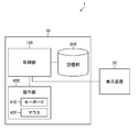
- FIG. 1 is a diagram showing a configuration of an information display system.
- FIG. 2 is a diagram showing a functional configuration of the processing unit.
- FIG. 3 is a diagram showing information stored in the storage unit.
- FIG. 4 is a flowchart showing the processing of the information display method.
- FIG. 5 is a diagram showing an example of displaying a list of damaged images.
- FIG. 6 is a diagram showing an example in which damage information is displayed in a list.
- FIG. 7 is a diagram showing a state of setting display conditions for damage information.
- FIG. 8 is a diagram showing an example of rearranged display of damage information.
- FIG. 9 is a diagram showing how the damage information is associated with the three-dimensional position.
- FIG. 10 is a diagram showing an example in which a three-dimensional position is highlighted.
- FIG. 11 is a diagram showing an example in which three-dimensional positions are directly displayed.
- FIG. 12 is a diagram showing another example of the identification display.
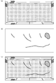
- FIG. 13 is a diagram showing another example of damage information.
- FIG. 14 is a flowchart for displaying damage information at a position selected on the three-dimensional model.
- FIG. 15 is a diagram showing a state in which damage information at a selected position on the three-dimensional model is displayed.
- FIG. 16 is a diagram showing a state of switching display of damage information and a three-dimensional model.
- FIG. 1 is a block diagram showing a configuration of the information display system 1 according to the first embodiment.
- the information display system 1 includes an information display device 10 (information display device) and a display device 20 (display device).
- the information display device 10 includes a processing unit 100, a storage unit 200, and an operation unit 400, and is connected to each other to transmit and receive necessary information. Further, the information display system 1 can connect to an external server (not shown), an external database, or the like via a communication control unit 114 (see FIG. 2) and a network (not shown), and acquire images and damage information as needed. it can.
- FIG. 2 is a diagram showing the configuration of the processing unit 100.
- the processing unit 100 includes a memory control unit 102 (memory control unit), a first display control unit 104 (first display control unit), a second display control unit 106 (second display control unit), and a reception unit 108 (reception unit). It includes a management category specifying unit 110 (management category specifying unit), a display switching unit 112 (display switching unit), and a communication control unit 114 (communication control unit). Each of these parts corresponds to a memory control function, a first display control function, a second display control function, a reception function, a management category identification function, and a communication control function among the functions of the information display program according to the present invention.
- the processing unit 100 further includes a CPU (CPU: Central Processing Unit), a ROM (ROM: Read Only Memory), and a RAM (RAM: Random Access Memory) (not shown). The processing by each of these parts is performed under the control of the CPU.
- CPU Central Processing Unit
- ROM Read Only Memory
- the functions of each part of the processing unit 100 described above can be realized by using various processors.
- the various processors include, for example, a CPU, which is a general-purpose processor that executes software (program) to realize various functions.
- the various processors described above include programmable logic devices (programmable logic devices), which are processors whose circuit configurations can be changed after manufacturing, such as GPU (Graphics Processing Unit) and FPGA (Field Programmable Gate Array), which are processors specialized in image processing. Programmable Logic Device (PLD) is also included.
- the above-mentioned various processors include a dedicated electric circuit, which is a processor having a circuit configuration specially designed for executing a specific process such as an ASIC (Application Specific Integrated Circuit).
- ASIC Application Specific Integrated Circuit
- each part may be realized by one processor, or may be realized by a plurality of processors of the same type or different types (for example, a plurality of FPGAs, or a combination of a CPU and an FPGA, or a combination of a CPU and a GPU). Further, one processor may realize a plurality of functions. As an example of configuring a plurality of functions with one processor, first, as represented by a computer such as a client and a server, one processor is configured by a combination of one or more CPUs and software, and this processor is configured. Is realized as a plurality of functions.
- SoC System On Chip
- a code readable by a computer of the software for example, various processors and electric circuits constituting the processing unit 100, and / or a combination thereof.
- the software stored in the non-temporary recording medium is an information display having a program (first display control function, reception function, management classification identification function, second display control function) for executing the information display method according to the present invention. Program) is included.
- the program code may be recorded in a non-temporary recording medium such as various optical magnetic recording devices or semiconductor memories instead of the ROM.
- RAM is used as a temporary storage area
- data stored in an EEPROM (Electronically Erasable and Programmable Read Only Memory) can also be referred to, for example.
- the storage unit 200 (storage unit) is composed of a non-temporary recording medium such as a DVD (Digital Versatile Disk), a hard disk (Hard Disk), various semiconductor memories, and a control unit thereof, and is a structure (building) as shown in FIG. , Bridges, roads, tunnels, dams, etc.) 3D model 202 (3D model) and damage information 204 (damage information) for each management category of the structure are stored in association with each other.
- the 3D model 202 shows the 3D shape of the structure and is represented by a 3D point group of many points on the surface of the structure, and is a polygonal polygon (for example, a triangular patch) based on the 3D point group.
- the surface of the structure is represented by an aggregate of the above, or the photographed image (texture) obtained by photographing the structure on a polygonal polygon is texture-mapped.
- the damage information 204 is at least one or more of a damage image corresponding to a management category, a damage image on which information indicating damage is superimposed, a damage diagram, a damage quantity table, a repair diagram, and a repair quantity table.
- the display device 20 displays damage information and a three-dimensional model of the structure under the control of the information display device 10.
- the operation unit 400 includes a keyboard 410 and a mouse 420 as input devices or pointing devices, and the user can execute the information display method and the information display program according to the present invention through the screens of these devices and the display device 20. You can perform the necessary operations (described later).
- the display device 20 may be configured with a touch panel so that the user can operate through the touch panel.
- the first display control unit 104 selects information to be displayed based on the user's operation via the operation unit 400 (step S100: first display control step). .. Specifically, the first display control unit 104 uses the damage information (damage image, damage image on which information indicating damage is superimposed, damage diagram, damage quantity table, repair diagram, and repair quantity) stored in the storage unit 200. Select which of the tables to display). It should be noted that these damage information may be acquired from an external server, a storage device, an image pickup device, or the like via the communication control unit 114, or may be acquired via a recording medium.
- damage information damage image, damage image on which information indicating damage is superimposed, damage diagram, damage quantity table, repair diagram, and repair quantity
- the first display control unit 104 causes the display device 20 (display device) to display a list of the selected damage information (step S110: first display control step).
- FIG. 5 is a diagram showing a list of damage images 500 to 510 as an example of damage information.
- the damage image may be an image on which information indicating damage (for example, a line segment indicating a crack, a circumscribed circle or a circumscribed rectangle of a peeling range, a figure or a symbol indicating the position of damage, etc.) is superimposed.
- the storage unit 200 stores the image in association with the damage information (type, member or division, position, size, degree, etc.) indicated by the image, and the first display control unit 104 is related to the image and the image. It may be displayed together with the information.
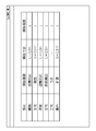
- FIG. 6 is a diagram showing a state in which a damage quantity table is displayed as an example of damage information.
- the damaged member, the type of damage, and the degree of damage are shown in association with each other.
- the degree of damage can be determined, for example, based on the "Bridge Periodic Inspection Procedure" of the Ministry of Land, Infrastructure, Transport and Tourism.
- FIGS. 5 and 6 an example of a damage image and a damage table is shown as one aspect of the damage information, but the damage image to be displayed in a list may be an ortho image (see part (a) of FIG. 13) or a damage diagram (FIG. (Refer to part (b) of the figure), “Ortho image + damage diagram” (part (c) of the same figure) may be used. Further, the damage information may be a repair drawing or a repair quantity table.
- the first display control unit 104 determines whether or not to reset the display conditions of the damage information displayed in the list (step S120: first display control step).
- the reception unit 108 reception unit, reception function
- the first display control unit 104 can determine that "the display condition is reset".
- the user can perform a display condition setting operation through, for example, a screen as shown in FIG. 7 displayed on the display device 20.
- FIG. 7 displayed on the display device 20.
- Step S130 First display control step.
- FIG. 8 is a diagram showing an example in which damages of degrees c and d are extracted from the table of FIG. In this way, by resetting and redisplaying the display conditions, the user can display only the damage information associated with the three-dimensional model that he / she is interested in.
- the reception unit 108 determines whether or not the selection of the damage information listed in steps S110 and S130 has been accepted (step S140: reception process).
- the reception unit 108 can determine that "selection has been accepted" when there is a user selection operation (for example, an operation of clicking an image or damage information with the mouse 420) via the operation unit 400.
- the management division identification unit 110 (management division identification unit, management division identification function) is a three-dimensional position in the three-dimensional model, and specifies the three-dimensional position corresponding to the damage information for which the selection has been accepted (step S150: three-dimensional). Position identification process, control classification identification process).
- the management division identification unit 110 stores, for example, a table in which the damage information and the three-dimensional coordinates of the representative points of the damage are associated with each other as shown in FIG. 9 in the storage unit 200, and by referring to this table, 3 The dimensional position can be specified.
- the damage information table as shown in FIG. 6 may be provided with columns for representative points and management categories, and the damage information table and the management category specific table may be shared. For example, the start point, end point, intermediate point, circumscribed circle, center of circumscribed circle, etc. of the damage can be set as the representative points of the damage, and the TOF method (TOF: The representative point can be measured by Time of Flight) or the like.
- the management category specifying unit 110 specifies a management category including the three-dimensional position specified in step S150 (step S160: management category specifying step).
- the management division is at least one of the parts constituting the structure, the division of the inspection unit of the member, and the three-dimensional coordinates of the structure.
- the management division is at least one of the parts constituting the structure, the division of the inspection unit of the member, and the three-dimensional coordinates of the structure.
- the management division is at least one of the parts constituting the structure, the division of the inspection unit of the member, and the three-dimensional coordinates of the structure.
- the management division is at least one of the parts constituting the structure, the division of the inspection unit of the member, and the three-dimensional coordinates of the structure.
- the management division is at least one of the parts constituting the structure, the division of the inspection unit of the member, and the three-dimensional coordinates of the structure.
- the management division in which members are finely divided such as a coffer for a floor slab, or three-dimensional coordinate
- a management division may be set for each member.
- the management division specifying unit 110 can specify the management division by referring to the correspondence table between the three-dimensional position and the management division as shown in FIG. 9, for example.
- the second display control unit 106 makes it possible to identify the specified three-dimensional position in the range including at least the management division specified in step S160 of the three-dimensional model.
- Display on the display device 20 step S170: second display control step.
- "to be identifiable” is not limited to the case where the three-dimensional position specified in step S150 is pinpointed (accurately at one point), but is the rough position of the specified three-dimensional position, or 3 It also includes the case where the area including the dimensional position is displayed so that it can be seen.
- the information display system 1 repeats the processes of steps S100 to S170 until the process is completed by a user's instruction or the like via the operation unit 400 (until YES is obtained in step S180).
- the second display control unit 106 controls the third display state in which the three-dimensional model is identified and displayed, and / or the viewpoint position and / or the line-of-sight direction with respect to the three-dimensional position.
- Display according to the display state step S170: second display control step.
- the first display state is a mode in which an index indicating the range including the three-dimensional position and / or the management division specified in step S150 is superimposed and displayed on the three-dimensional model, and the second display state is specified in step S150.
- the 3D model is displayed according to the viewpoint position and the line-of-sight direction facing the 3D position.
- FIG. 10 is a diagram showing an example in which damage information and a three-dimensional model are displayed according to the first display state.
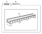
- the first display control unit 104 displays the damage information in the first display area 21 (first display area) of the display device 20 (assuming that the damage information 21A is selected), and the second display device 20 is selected.
- the display control unit 106 displays the three-dimensional model 30 of the bridge in the second display area 22 (second display area) of the display device 20. What is displayed in the second display area 22 is the range of the three-dimensional model 30 of the bridge including the management division specified in step S160. Further, the second display control unit 106 superimposes and displays the index 32 indicating the specified three-dimensional position on the three-dimensional model.
- the second display control unit 106 can display, for example, a polygonal polygon in which a photographed image (texture) obtained by photographing a structure is texture-mapped as a three-dimensional model. The user can magnify and display such a three-dimensional model and confirm the properties of the surface of the bridge (coffer).
- FIG. 11 is a diagram showing a display example in the second display state.
- the second display control unit 106 enlarges or reduces, translates, or rotates the 3D model based on the specified 3D position to move the viewpoint position and / or the line of sight with respect to the 3D position.
- the direction is controlled, and the three-dimensional model is displayed in the second display area 22 according to the viewpoint position and the line-of-sight direction facing the specified three-dimensional position 22B.
- the second display control unit 106 performs operations such as multiplication of the coordinate transformation matrix based on the three-dimensional position (x, y, z) and the surface information (normal vector) as shown in the following equation (1). By doing so, the viewpoint position and / or the line-of-sight direction can be controlled.
- the rotation angle is ( ⁇ , ⁇ , ⁇ ), (x, y, z) is the original coordinates, and (X, Y, Z) is the converted coordinates.
- first display state and second display state Only one of the above-mentioned first display state and second display state may be used, or both may be used at the same time.
- the management including the 3D position 22B in the viewpoint position and the line-of-sight direction (that is, the state in which the 3D model is moved, enlarged, etc.) facing the 3D position 22B.
- the frame 22C one aspect of the index
- the index 22D indicating the three-dimensional position 22B may be superimposed and displayed at the viewpoint position and the line-of-sight direction facing the three-dimensional position 22B. Note that FIG. 12 shows only the second display area 22.
- the three-dimensional model is displayed in step S170, but the three-dimensional model is displayed according to the initial setting position, size, and orientation at the time of starting the process (step S100 or step S110). Then, it may be redisplayed (moving, rotating, enlarging / reducing, etc. the 3D model in the initial state) according to the selection of the damage information.
- the reception unit 108 determines whether or not the designation of the three-dimensional position has been accepted (step S200). This determination can be made by the presence or absence of a three-dimensional position designation operation (for example, clicking the position of the three-dimensional model with the mouse 420) via the operation unit 400.
- the management division identification unit 110 identifies the management division to which the damage having the representative point closest to the designated three-dimensional position belongs (step S210).
- the management category specifying unit 110 can make this determination by referring to the correspondence table as shown in FIG.
- the first display control unit 104 causes the display device 20 to display the damage information (damage information corresponding to the designated three-dimensional position) existing in the specified management category (step S220).
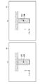
- FIG. 15 is a diagram showing a display example of damage information according to the designation of the three-dimensional position.
- the first display is performed.
- the control unit 104 displays the damage information 23A in the first display area 23 on the left side of the figure.
- the damage information 23A the one surrounded by the frame 23B is the damage closest to the designated three-dimensional position.
- FIG. 16 is a diagram showing an example of switching display, in which a first display area 21 on which damage information is displayed in a list and a second display area 22 on which a three-dimensional model is displayed are overlapped (second display area 22). Is the front).
- the display switching unit 112 switches the display on the display device 20 according to the selection.
- the user can quickly and easily grasp the position of the damage of interest on the three-dimensional model.
- Information display system 10 Information display device 20 Display device 21 First display area 21A Damage information 22 Second display area 22B Three-dimensional position 22C Frame 22D Index 23 First display area 23A Damage information 23B Frame 24 Second display area 24A Cursor 30 3D model 32 Index 100 Processing unit 102 Storage control unit 104 1st display control unit 106 2nd display control unit 108 Reception unit 110 Management division identification unit 112 Display switching unit 114 Communication control unit 200 Storage unit 202 3D model 204 Damage information 400 Operation unit 410 Keyboard 420 Mouse 500 Damage image 502 Damage image 504 Damage image 506 Damage image 508 Damage image 510 Damage images S100 to S180 Steps of information display method S200 to S230 Steps of information display method
Landscapes
- Engineering & Computer Science (AREA)
- Theoretical Computer Science (AREA)
- Physics & Mathematics (AREA)
- General Physics & Mathematics (AREA)
- General Engineering & Computer Science (AREA)
- Computer Graphics (AREA)
- Software Systems (AREA)
- Computer Vision & Pattern Recognition (AREA)
- Computer Hardware Design (AREA)
- Architecture (AREA)
- Geometry (AREA)
- Human Computer Interaction (AREA)
- Computing Systems (AREA)
- Quality & Reliability (AREA)
- Processing Or Creating Images (AREA)
- User Interface Of Digital Computer (AREA)
Priority Applications (2)
| Application Number | Priority Date | Filing Date | Title |
|---|---|---|---|
| JP2021534573A JP7407194B2 (ja) | 2019-07-22 | 2020-05-29 | 情報表示装置、情報表示方法、及び情報表示プログラム |
| US17/572,783 US11887268B2 (en) | 2019-07-22 | 2022-01-11 | Information display device, information display method, and information display program |
Applications Claiming Priority (2)
| Application Number | Priority Date | Filing Date | Title |
|---|---|---|---|
| JP2019-134584 | 2019-07-22 | ||
| JP2019134584 | 2019-07-22 |
Related Child Applications (1)
| Application Number | Title | Priority Date | Filing Date |
|---|---|---|---|
| US17/572,783 Continuation US11887268B2 (en) | 2019-07-22 | 2022-01-11 | Information display device, information display method, and information display program |
Publications (1)
| Publication Number | Publication Date |
|---|---|
| WO2021014758A1 true WO2021014758A1 (ja) | 2021-01-28 |
Family
ID=74194157
Family Applications (1)
| Application Number | Title | Priority Date | Filing Date |
|---|---|---|---|
| PCT/JP2020/021338 Ceased WO2021014758A1 (ja) | 2019-07-22 | 2020-05-29 | 情報表示装置、情報表示方法、及び情報表示プログラム |
Country Status (3)
| Country | Link |
|---|---|
| US (1) | US11887268B2 (https=) |
| JP (1) | JP7407194B2 (https=) |
| WO (1) | WO2021014758A1 (https=) |
Cited By (1)
| Publication number | Priority date | Publication date | Assignee | Title |
|---|---|---|---|---|
| JP2024010860A (ja) * | 2022-07-13 | 2024-01-25 | 株式会社Soken | 構造物の損傷表示装置 |
Citations (2)
| Publication number | Priority date | Publication date | Assignee | Title |
|---|---|---|---|---|
| WO2017043275A1 (ja) * | 2015-09-10 | 2017-03-16 | 富士フイルム株式会社 | 健全度判定装置、健全度判定方法および健全度判定プログラム |
| JP2019049951A (ja) * | 2017-09-12 | 2019-03-28 | 西日本旅客鉄道株式会社 | 構造物管理装置、構造物管理方法、及び構造物管理プログラム |
Family Cites Families (3)
| Publication number | Priority date | Publication date | Assignee | Title |
|---|---|---|---|---|
| JP2002042172A (ja) * | 2000-07-25 | 2002-02-08 | Matsushita Electric Works Ltd | 仮想物体の選択方法、この方法が適用される記録媒体およびサービス |
| JP2003242524A (ja) | 2002-02-19 | 2003-08-29 | Fukui Computer Kk | 画像表示装置、画像表示方法、画像表示プログラムおよび画像表示プログラムが格納された記憶媒体 |
| JP4398885B2 (ja) * | 2005-03-07 | 2010-01-13 | 株式会社東芝 | 設備位置提示システム |
-
2020
- 2020-05-29 JP JP2021534573A patent/JP7407194B2/ja active Active
- 2020-05-29 WO PCT/JP2020/021338 patent/WO2021014758A1/ja not_active Ceased
-
2022
- 2022-01-11 US US17/572,783 patent/US11887268B2/en active Active
Patent Citations (2)
| Publication number | Priority date | Publication date | Assignee | Title |
|---|---|---|---|---|
| WO2017043275A1 (ja) * | 2015-09-10 | 2017-03-16 | 富士フイルム株式会社 | 健全度判定装置、健全度判定方法および健全度判定プログラム |
| JP2019049951A (ja) * | 2017-09-12 | 2019-03-28 | 西日本旅客鉄道株式会社 | 構造物管理装置、構造物管理方法、及び構造物管理プログラム |
Cited By (1)
| Publication number | Priority date | Publication date | Assignee | Title |
|---|---|---|---|---|
| JP2024010860A (ja) * | 2022-07-13 | 2024-01-25 | 株式会社Soken | 構造物の損傷表示装置 |
Also Published As
| Publication number | Publication date |
|---|---|
| US20220130129A1 (en) | 2022-04-28 |
| JPWO2021014758A1 (https=) | 2021-01-28 |
| JP7407194B2 (ja) | 2023-12-28 |
| US11887268B2 (en) | 2024-01-30 |
Similar Documents
| Publication | Publication Date | Title |
|---|---|---|
| Ferreira et al. | Urbane: A 3D framework to support data driven decision making in urban development | |
| US20120030630A1 (en) | Multiscale three-dimensional orientation | |
| US12069224B2 (en) | Image display apparatus, image display method, and image display program | |
| JP7420815B2 (ja) | 3d幾何抽出のために画像の複数から相補的画像を選択するシステムおよび方法 | |
| KR20180132183A (ko) | 모바일 단말, 지하 시설물 관리서버 및 이를 포함하는 3d 공간정보에 기반한 지하 시설물 관리 시스템 | |
| JP6230076B2 (ja) | 仮想サーフェス割り当て | |
| JP7557600B2 (ja) | 情報表示装置、方法及びプログラム | |
| JP2022123068A (ja) | 高精度マップの横断歩道の生成方法、装置及び電子機器 | |
| US20220130029A1 (en) | Image display apparatus, image display method, and image display program | |
| US8314791B2 (en) | Method and apparatus for determining view impact | |
| JP7407194B2 (ja) | 情報表示装置、情報表示方法、及び情報表示プログラム | |
| US20220406018A1 (en) | Three-dimensional display device, three-dimensional display method, and three-dimensional display program | |
| EP4421748A1 (en) | Rendering of a geospatial scene | |
| JP7806910B2 (ja) | 学習装置、画像処理装置、学習方法、画像処理方法、及びコンピュータプログラム | |
| JP7594933B2 (ja) | 情報処理装置 | |
| KR100751397B1 (ko) | 영상 처리 방법 | |
| CN118411115A (zh) | 基于bim技术的建筑监控方法、系统、计算机设备及存储器 | |
| CN121997427A (zh) | 斜拉桥模型的生成方法、装置、设备、介质及产品 | |
| CN119648964A (zh) | 一种点云标注方法及装置 | |
| Chang et al. | A 3D GIS Perspective Towards the Occlusion Problem in XR Environment | |
| JPH05165922A (ja) | Cadシステムにおける3次元視点確認方法 |
Legal Events
| Date | Code | Title | Description |
|---|---|---|---|
| 121 | Ep: the epo has been informed by wipo that ep was designated in this application |
Ref document number: 20844229 Country of ref document: EP Kind code of ref document: A1 |
|
| DPE1 | Request for preliminary examination filed after expiration of 19th month from priority date (pct application filed from 20040101) | ||
| ENP | Entry into the national phase |
Ref document number: 2021534573 Country of ref document: JP Kind code of ref document: A |
|
| NENP | Non-entry into the national phase |
Ref country code: DE |
|
| 122 | Ep: pct application non-entry in european phase |
Ref document number: 20844229 Country of ref document: EP Kind code of ref document: A1 |