WO2021014586A1 - Autonomous work machine, autonomous work machine control method and program - Google Patents
Autonomous work machine, autonomous work machine control method and program Download PDFInfo
- Publication number
- WO2021014586A1 WO2021014586A1 PCT/JP2019/028902 JP2019028902W WO2021014586A1 WO 2021014586 A1 WO2021014586 A1 WO 2021014586A1 JP 2019028902 W JP2019028902 W JP 2019028902W WO 2021014586 A1 WO2021014586 A1 WO 2021014586A1
- Authority
- WO
- WIPO (PCT)
- Prior art keywords
- marker
- markers
- autonomous
- work machine
- information
- Prior art date
Links
- 238000000034 method Methods 0.000 title claims description 81
- 239000003550 marker Substances 0.000 claims abstract description 294
- 238000001514 detection method Methods 0.000 claims abstract description 23
- 238000004891 communication Methods 0.000 claims description 17
- 230000033001 locomotion Effects 0.000 claims description 9
- 230000008569 process Effects 0.000 description 24
- 238000012545 processing Methods 0.000 description 16
- 230000005484 gravity Effects 0.000 description 8
- 238000005259 measurement Methods 0.000 description 7
- 230000007246 mechanism Effects 0.000 description 6
- 238000010586 diagram Methods 0.000 description 5
- 238000013519 translation Methods 0.000 description 5
- 230000001133 acceleration Effects 0.000 description 4
- 230000006870 function Effects 0.000 description 4
- 238000013459 approach Methods 0.000 description 3
- 238000012986 modification Methods 0.000 description 3
- 230000004048 modification Effects 0.000 description 3
- 239000003086 colorant Substances 0.000 description 2
- 240000004050 Pentaglottis sempervirens Species 0.000 description 1
- 235000004522 Pentaglottis sempervirens Nutrition 0.000 description 1
- 239000003795 chemical substances by application Substances 0.000 description 1
- 230000009545 invasion Effects 0.000 description 1
- 238000010801 machine learning Methods 0.000 description 1
- 238000011084 recovery Methods 0.000 description 1
- 238000000638 solvent extraction Methods 0.000 description 1
Images


Classifications
-
- G—PHYSICS
- G05—CONTROLLING; REGULATING
- G05D—SYSTEMS FOR CONTROLLING OR REGULATING NON-ELECTRIC VARIABLES
- G05D1/00—Control of position, course or altitude of land, water, air, or space vehicles, e.g. automatic pilot
- G05D1/02—Control of position or course in two dimensions
- G05D1/021—Control of position or course in two dimensions specially adapted to land vehicles
- G05D1/0212—Control of position or course in two dimensions specially adapted to land vehicles with means for defining a desired trajectory
- G05D1/0214—Control of position or course in two dimensions specially adapted to land vehicles with means for defining a desired trajectory in accordance with safety or protection criteria, e.g. avoiding hazardous areas
-
- G—PHYSICS
- G05—CONTROLLING; REGULATING
- G05D—SYSTEMS FOR CONTROLLING OR REGULATING NON-ELECTRIC VARIABLES
- G05D1/00—Control of position, course or altitude of land, water, air, or space vehicles, e.g. automatic pilot
- G05D1/02—Control of position or course in two dimensions
- G05D1/021—Control of position or course in two dimensions specially adapted to land vehicles
- G05D1/0231—Control of position or course in two dimensions specially adapted to land vehicles using optical position detecting means
- G05D1/0234—Control of position or course in two dimensions specially adapted to land vehicles using optical position detecting means using optical markers or beacons
-
- G—PHYSICS
- G05—CONTROLLING; REGULATING
- G05D—SYSTEMS FOR CONTROLLING OR REGULATING NON-ELECTRIC VARIABLES
- G05D1/00—Control of position, course or altitude of land, water, air, or space vehicles, e.g. automatic pilot
- G05D1/02—Control of position or course in two dimensions
- G05D1/021—Control of position or course in two dimensions specially adapted to land vehicles
- G05D1/0231—Control of position or course in two dimensions specially adapted to land vehicles using optical position detecting means
- G05D1/0246—Control of position or course in two dimensions specially adapted to land vehicles using optical position detecting means using a video camera in combination with image processing means
- G05D1/0251—Control of position or course in two dimensions specially adapted to land vehicles using optical position detecting means using a video camera in combination with image processing means extracting 3D information from a plurality of images taken from different locations, e.g. stereo vision
-
- G—PHYSICS
- G05—CONTROLLING; REGULATING
- G05D—SYSTEMS FOR CONTROLLING OR REGULATING NON-ELECTRIC VARIABLES
- G05D1/00—Control of position, course or altitude of land, water, air, or space vehicles, e.g. automatic pilot
- G05D1/02—Control of position or course in two dimensions
- G05D1/021—Control of position or course in two dimensions specially adapted to land vehicles
- G05D1/0276—Control of position or course in two dimensions specially adapted to land vehicles using signals provided by a source external to the vehicle
- G05D1/0278—Control of position or course in two dimensions specially adapted to land vehicles using signals provided by a source external to the vehicle using satellite positioning signals, e.g. GPS
Definitions
- the present invention relates to an autonomous work machine, a control method and a program of the autonomous work machine.
- Patent Document 1 discloses that when a marker is recognized, the position information of the marker stored in the robot vehicle is read out to grasp the current position of the robot vehicle.
- the present invention has been made with the recognition of the above problems as an opportunity, and an object of the present invention is to provide a technique for controlling a working machine by using markers that do not need to be individually distinguished.
- the autonomous working machine An autonomous work machine that works in the work area
- FIG. 1 is an external view of an autonomous working machine capable of autonomous traveling according to an embodiment of the present invention.
- the traveling direction (vehicle length direction) of the autonomous work equipment in the side view the lateral direction (vehicle width direction) orthogonal to the traveling direction, and the vertical direction orthogonal to the traveling direction and the lateral direction are shown in the front-rear direction and the left-right direction, respectively.
- the direction and the vertical direction are defined, and the configuration of each part is explained accordingly.
- reference numeral 10 indicates an autonomous work machine (hereinafter referred to as “work vehicle”). Specifically, the work vehicle 10 functions as a lawnmower that travels autonomously. However, the lawnmower is an example, and the present invention can be applied to other types of work machines.
- the work vehicle 10 includes a camera unit 11 including a plurality of cameras (first camera 11a, second camera 11b), and captures images taken by the first camera 11a and the second camera 11b having parallax. It is used to calculate and acquire distance information between an object existing in front and the work vehicle 10. Then, the operation of the work vehicle 10 is controlled based on the captured image and the object recognition model held in advance.
- FIG. 2 is a view of the work vehicle 10 observed from the lateral direction (vehicle width direction).
- the work vehicle 10 includes a camera unit 11, a vehicle body 12, a stay 13, a front wheel 14, a rear wheel 16, a blade 20, a work motor 22, a motor holding member 23, a blade height adjusting motor 100, and a blade height adjusting motor 100.
- the translation mechanism 101 is provided.
- the work vehicle 10 includes a traveling motor 26, various sensor groups S, an electronic control unit (ECU: Electronic Control Unit) 44, a charging unit 30, a battery (battery) 32, a charging terminal 34, and a communication unit 35. ..
- ECU Electronic Control Unit
- the vehicle body 12 of the work vehicle 10 has a chassis 12a and a frame 12b attached to the chassis 12a.
- the front wheels 14 are two small-diameter left and right wheels fixed to the front side of the chassis 12a via a stay 13 in the front-rear direction.
- the rear wheels 16 are two large-diameter left and right wheels attached to the rear side of the chassis 12a.
- the blade 20 is a rotary blade for lawn mowing work that is attached near the center position of the chassis 12a.
- the work motor 22 is an electric motor arranged above the blade 20.
- the blade 20 is connected to the work motor 22 and is rotationally driven by the work motor 22.
- the motor holding member 23 holds the working motor 22.
- the rotation of the motor holding member 23 is restricted with respect to the chassis 12a, and the motor holding member 23 is allowed to move in the vertical direction by, for example, a combination of a guide rail and a slider that is guided by the guide rail and can move up and down. ..
- the blade height adjusting motor 100 is a motor for adjusting the height of the blade 20 in the vertical direction with respect to the ground plane GR.
- the translation mechanism 101 is connected to the blade height adjusting motor 100, and is a mechanism for converting the rotation of the blade height adjusting motor 100 into translational movement in the vertical direction.
- the translation mechanism 101 is also connected to a motor holding member 23 that holds the work motor 22.
- the rotation of the blade height adjusting motor 100 is converted into translational movement (movement in the vertical direction) by the translation mechanism 101, and the translational movement is transmitted to the motor holding member 23. Due to the translational movement (movement in the vertical direction) of the motor holding member 23, the work motor 22 held by the motor holding member 23 also moves in translation (movement in the vertical direction).
- the height of the blade 20 with respect to the ground plane GR can be adjusted by moving the work motor 22 in the vertical direction.
- the traveling motor 26 is two electric motors (motors) attached to the chassis 12a of the work vehicle 10.
- the two electric motors are connected to the left and right rear wheels 16, respectively.
- the work vehicle 10 can be moved in various directions by independently rotating the left and right wheels forward (rotating in the forward direction) or reversing (rotating in the backward direction) with the front wheels 14 as the trailing wheels and the rear wheels 16 as the driving wheels. Can be made to.
- the charging terminal 34 is a charging terminal provided at a front end position in the front-rear direction of the frame 12b, and can be charged by connecting to a corresponding terminal of a charging station (for example, a charging station 300 described later with reference to FIG. 3). You can receive power from the station.
- the charging terminal 34 is connected to the charging unit 30 via wiring, and the charging unit 30 is connected to the battery 32. Further, the work motor 22, the traveling motor 26, and the blade height adjusting motor 100 are also connected to the battery 32, and are configured to be supplied with power from the battery 32.
- the ECU 44 is an electronic control unit including a microcomputer configured on a circuit board, and controls the operation of the work vehicle 10. Details of the ECU 44 will be described later.
- the communication unit 35 provides information to an external device (for example, a charging station described later, a communication terminal owned by the user, a remote controller for operating the work vehicle 10, etc.) connected to the work vehicle 10 by wire or wirelessly. Can be sent and received.
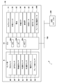
- FIG. 3 is a diagram showing a configuration example of a control system according to an embodiment of the present invention.
- the control system 1 includes a work vehicle 10 and a charging station 300. It should be noted that a remote controller for operating a communication terminal or a work vehicle 10 owned by a user, which will be described later, may be further included.
- the ECU 44 included in the work vehicle 10 includes a CPU 44a, an I / O 44b, and a memory 44c.
- the I / O 44b inputs / outputs various information.
- the memory 44c is a ROM (Read Only Memory), an EEPROM (Electrically Erasable Programmable Read Only Memory), a RAM (Random Access Memory), or the like.
- ROM Read Only Memory
- EEPROM Electrically Erasable Programmable Read Only Memory
- RAM Random Access Memory
- a photographed image, a work schedule of the work vehicle 10, map information regarding the work area, various programs for controlling the operation of the work vehicle 10, and the like are stored.
- the ECU 44 can operate as each processing unit for realizing the present invention by reading and executing the program stored in the memory 44c.
- the ECU 44 is connected to various sensor groups S.
- the sensor group S includes an orientation sensor 46, a GPS sensor 48, a wheel speed sensor 50, an angular speed sensor 52, an acceleration sensor 54, a current sensor 62, and a blade height sensor 64.
- the orientation sensor 46 and the GPS sensor 48 are sensors for acquiring information on the orientation and position of the work vehicle 10.
- the azimuth sensor 46 detects the azimuth according to the geomagnetism.
- the GPS sensor 48 receives radio waves from GPS satellites and detects information indicating the current position (latitude, longitude) of the work vehicle 10.
- an odometry and an inertial measurement unit IMU: Inertial Measurement Unit may be provided.
- the wheel speed sensor 50, the angular velocity sensor 52, and the acceleration sensor 54 are sensors for acquiring information on the moving state of the work vehicle 10.
- the wheel speed sensor 50 detects the wheel speeds of the left and right rear wheels 16.
- the angular velocity sensor 52 detects the angular velocity around the vertical axis (z-axis in the vertical direction) of the position of the center of gravity of the work vehicle 10.
- the acceleration sensor 54 detects the acceleration in the orthogonal three-axis directions of the x, y, and z axes acting on the work vehicle 10.
- the current sensor 62 detects the current consumption (power consumption) of the battery 32.
- the detection result of the current consumption (power consumption) is stored in the memory 44c of the ECU 44.
- the ECU 44 performs return control for returning the work vehicle 10 to the charging station 300 for charging.
- the daily work schedule may be stored in the memory 44c, and the return control may be performed according to the completion of the work to be performed on that day.
- the blade height sensor 64 detects the height of the blade 20 with respect to the ground plane GR.
- the detection result of the blade height sensor 64 is output to the ECU 44.
- the blade height adjusting motor 100 is driven, and the blade 20 moves up and down in the vertical direction to adjust the height from the ground plane GR.
- the outputs of the various sensor groups S are input to the ECU 44 via the I / O 44b.
- the ECU 44 supplies electric power from the battery 32 to the traveling motor 26, the working motor 22, and the height adjusting motor 100 based on the outputs of the various sensor groups S.
- the ECU 44 outputs a control value via the I / O 44b to control the traveling motor 26, thereby controlling the traveling of the work vehicle 10.
- the height of the blade 20 is adjusted by outputting a control value via the I / O 44b to control the height adjusting motor 100.
- the rotation of the blade 20 is controlled by outputting a control value via the I / O 44b to control the work motor 22.
- the I / O 44b can function as a communication interface and can be connected to other devices by wire or wirelessly via the network 150.
- the charging station 300 functions as a charging device for charging the battery (battery 32) of the work vehicle 10.
- the work vehicle 10 is installed in the work area, and can be charged by returning to the charging station 300 and connecting the charging terminal 34 to the charging station 300.
- a virtual line is a virtual line connecting markers arranged to define a work area.
- 400 indicates an area (for example, the entire site owned by the user) including a work area (for example, a garden) on which the work vehicle 10 works.
- 401a to 401n are markers according to this embodiment. The area surrounded by these markers 401a to 401n is the work area.
- the work vehicle 10 performs work so as not to deviate from this work area by controlling so as not to deviate from the area deeper than the virtual line.
- the work area may be defined by partitioning the entire site using an existing area wire embedded in the ground and arranging a marker on a part of the site to provide a non-invasion area. That is, the present invention can also be applied when a work area is defined by combining an existing area wire and a marker.
- the recognizable range includes four markers, markers 401a to 401d.
- the work vehicle 10 sets a virtual line (virtual wire) between two adjacent markers.
- a virtual line 411 is set between the marker 401a and the marker 401b
- a virtual line 412 is set between the marker 401b and the marker 401c
- a virtual line 413 is set between the marker 401c and the marker 401d. Note that, for example, since the marker 401b and the marker 401d are not adjacent markers, a virtual line is not set.
- the virtual line is not limited to a straight line.
- it may be a smooth curve such as a virtual line 431 set between the marker 401i and the marker 401j.
- ⁇ Judgment method of adjacent markers 1 Distance between markers> Whether or not the two markers are adjacent markers can be determined based on the distance between the markers, assuming that the markers are arranged at predetermined distance intervals. If the distance between the markers is within the predetermined distance range (for example, 2.5 m to 3.5 m), it is determined that the markers are adjacent, and if the distance is outside the predetermined distance range, it is determined that the markers are not adjacent. May be good. In FIG. 4A, since the length of the line 414 (for example, 4 m) is out of the predetermined distance range, it is not set as a virtual line. This makes it possible to prevent the work from not being performed in the triangular region connecting the markers 401b, the markers 401c, and the markers 401d.
- the predetermined distance range for example, 2.5 m to 3.5 m
- the predetermined distance range does not have to have an upper limit value or a lower limit value such as 2.5 m or more, 3 m or more, 3 m or less, 3.5 m or less.
- the method of determining whether or not two markers are adjacent markers is not limited to the method of using the distance between the markers.
- a marker having an index for example, 431, 432 for indicating the direction in which adjacent markers exist, such as the marker 401m in FIG. 4A
- each index is detected, and the indexes 431 and 432 are used.
- a nearby marker existing in the pointing direction may be determined to be an adjacent marker.
- the virtual line 421 is set between the marker 401l and the marker 401m existing in the direction indicated by the index 431, and the virtual line 422 is set between the marker 401n and the marker 401n.
- each marker may be configured to include an index indicating at least two directions as in the case of 401 m.
- each marker has an index indicating the direction in which the adjacent marker exists, and the second marker existing in the direction indicated by the index of the first marker is adjacent to the index. It can be specified as a marker.
- the marker existing closest to the marker may be specified as an adjacent marker.
- a marker in the direction indicated by the index and within a predetermined distance range for example, 2.5 m to 3.5 m
- the direction indicated by the index may be freely changed by the user.
- the direction of the index may be adjustable by using a rotation mechanism or the like.
- ⁇ Judgment method of adjacent marker 3 Marker detected in the back>
- three markers are arranged in an equilateral triangle shape at predetermined distance (for example, 3 m) intervals, or four markers are arranged in a square shape at predetermined distance (for example, 3 m) intervals.
- predetermined distance for example, 3 m
- square shape at predetermined distance (for example, 3 m) intervals.
- FIG. 4B is an explanatory diagram of a method for determining adjacent markers in a work area where an equilateral triangle or square area is formed.
- Reference numeral 450 denotes an area (for example, the entire site owned by the user) including a work area (for example, a garden) on which the work vehicle 10 works.
- 451a to 451p are markers according to the present embodiment. The area surrounded by these markers 451a to 451p is the work area. The work vehicle 10 works so as not to deviate from this work area.
- the markers 451a to 451p are arranged at predetermined distances (for example, 3 m).
- an equilateral triangle region is formed by three markers, a marker 451b, a marker 451c, and a marker 451d.
- a square region is formed by four markers, a marker 451l, a marker 451m, a marker 451n, and a marker 451o. If there is such an area, when the determination method 1 is used, the work vehicle 10 moves to a deeper area beyond the virtual line connecting the marker 451b and the marker 451c and the virtual line connecting the marker 451l and the marker 451o. You will not be able to work within these areas because you will not be able to.
- the two markers are not adjacent markers.
- two markers, the marker 451b and the marker 451d are detected, and another marker 451c is detected behind the two markers. Therefore, the two markers, the marker 451b and the marker 451d, are detected. Determine that the marker is not an adjacent marker.
- two markers, the marker 451l and the marker 451o are detected, and other markers 451m and 451n are detected behind the two markers. Therefore, the two markers 451l and the marker 451o are detected. Determine that the marker is not an adjacent marker.
- a virtual line is not set between the marker 451b and the marker 451c, and between the marker 451l and the marker 451o. Therefore, the work vehicle 10 enters the equilateral triangle area or the square area to perform the work. Is possible.
- the determination method 3 when another marker exists in the area behind the line connecting the two markers, it is specified that the two markers are not adjacent markers. However, when the determination method 3 is applied, if another marker located far away from the two markers is detected, it may accidentally advance to the inner region. Therefore, the distance to another marker is calculated, and it is determined that the calculated distance is less than or equal to a predetermined distance (for example, 4 m), or that the other marker is a marker adjacent to either of the two markers in front. Only in case, it may be configured to be movable to the back area. As a result, it is possible to prevent the player from entering an area that should not be entered.
- a predetermined distance for example, 4 m
- FIG. 4C is an explanatory diagram of an example of a method for determining adjacent markers.
- Reference numeral 460 indicates an area (for example, the entire site owned by the user) including a work area (for example, a garden) on which the work vehicle 10 works.
- 461a to 461m are markers according to the present embodiment. The area surrounded by these markers 461a to 461m is the work area. The work vehicle 10 works so as not to deviate from this work area.
- the user 462 Before starting the work by the work vehicle 10, the user 462 operates the remote controller 463 to directly control the work vehicle 10 and moves the work vehicle 10 once along each marker.
- the operation signal from the remote controller 463 is received via the communication unit 35 of the work vehicle 10.
- the work vehicle 10 has the GPS sensor 48, and stores the locus of tracing each marker in order according to the operation signal of the remote controller 463 as the locus information of the work area.
- the locus information of the work area can be grasped before the start of the work. Therefore, after the start of the work, the markers that do not follow the locus are determined to be non-adjacent markers. It is possible to determine whether a marker is an adjacent marker.
- the locus information of the work vehicle 10 is acquired by running the work vehicle 10 along each of the arranged markers. Thereby, among the plurality of markers, two markers that match the locus information can be specified as adjacent markers.
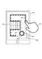
- FIG. 4D is a diagram showing an example of writing on a map regarding a work area displayed on a communication terminal owned by the user.
- Reference numeral 470 is a communication terminal of the user, for example, a tablet or a smartphone.
- 471 is a user's hand.
- Reference numeral 472 is map information regarding the work area displayed on the display screen of the communication terminal 470.
- a map showing a bird's-eye view of the site including the user's home and garden is displayed.
- 473 is the roof of the user's home and 474 is the tree space on the premises of the user's home.
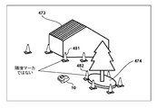
- FIG. 4E is an external view of a part of the site including the user's home corresponding to the map information of FIG. 4D.
- 475 indicates the boundary that the user is tracing on the map using the fingers of the hand 471.
- 476 indicates a boundary traced around the tree space by the user using the fingers of the hand 471.
- Tree space 474 is an island excluded from the work area. It should be noted that the boundary may be specified by connecting the positions pointed by the finger instead of tracing with the finger.
- the boundary of the work area is specified on the map displayed on the communication terminal 470, and the specified boundary information (information indicating the position of the boundary line) is transmitted to the work vehicle 10.
- the work vehicle 10 can acquire the boundary information specified by the user operation, so that the work vehicle 10 recognizes its own position and direction using the GPS sensor 48 and the direction sensor 46, and sets the self position and direction. It is possible to determine whether or not the two detected markers are adjacent markers by using the boundary information. In the example of FIG. 4E, the work vehicle 10 can determine from the acquired boundary information that the markers 481 and the markers 482 are not adjacent markers.
- the self-position and the directional may be recognized by using an odometry and an inertial measurement unit (IMU: Inertial Measurement Unit).
- IMU Inertial Measurement Unit
- the method of tracing the boundary is not limited to the method of tracing by the user using the finger of the hand 471.
- the user uses the finger of the hand 471 to sequentially specify the position of each marker along the boundary on a plurality of maps, thereby acquiring the marker placement information as the boundary information. You may. Then, the boundary information may be transmitted from the communication terminal 471 to the work vehicle 10.
- the work vehicle 10 can determine from the boundary information (marker arrangement information) that the markers 481 and the markers 482 are not adjacent markers.
- the boundary information of the work area designated on the map including the work area (for example, the arrangement information of a plurality of markers arranged at the boundary of the work area (point-designated position). Information) or the boundary line (line traced with a finger) indicating the boundary of the work area) is acquired. Thereby, among the plurality of markers, two markers matching the boundary information can be specified as adjacent markers.
- FIG. 4F shows an example of a method using two types of markers.
- Each marker placed on the boundary of the work area and each marker placed around the tree space 474 which is an island excluded from the work area have different types of markers (for example, different colors, different shapes, etc.). use.
- the work vehicle 10 can discriminate different types of markers from the characteristics of the markers extracted from the captured image, and the work vehicle 10 can use the photographed image to determine that the markers 483 and 484 are adjacent to each other. It can be determined that there is no such thing.
- the marker is not limited to two types, and when a plurality of islands exist, different types of markers may be used for each island. Therefore, it can be applied even when three or more types of markers are used.
- first-type markers that define the outer edge of the work area
- second-type markers that define an internal area (island) that is included in the outer edge and excluded from the work area.
- first type of marker and the second type of marker can be specified as not being adjacent markers.
- FIG. 4G is a diagram showing an example in which markers are arranged at short intervals in a region having an intricate shape.
- 491a to 491e are markers for the first distance (for example, 3 m) interval, respectively.
- 492a to 492f are markers for the second distance (for example, 1 m) interval, respectively.
- the first type of marker for the first distance interval and the second type of marker for the second distance interval are different types of markers having different colors, shapes, sizes, and the like, for example.
- the markers 491b, 491c, and 491d have a regular triangular shape
- the markers 491c, 491d, and 491e also have a regular triangular shape.
- the two markers are not adjacent markers, for example, the work vehicle heads between the markers 491c and 491d. Since the marker 491e is detected in the back of the vehicle, the vehicle may travel in the direction of approaching the marker 491e beyond the boundary of the work area connecting the marker 491c and the marker 491d.
- markers 492a to 492f are further arranged in a place having a complicated shape.
- the work vehicle 10 further detects the marker 492c and the marker 492d on the line connecting the marker 491c and the marker 491d, so that the two markers (marker 491c and the marker 491d) are adjacent markers. Can be determined. Therefore, it is possible to prevent the work vehicle 10 from deviating to the inner region beyond the boundary of the work area connecting the markers 491c and the markers 491d.
- the two markers, the marker 492c and the marker 492d are detected, but either the marker 492c or the marker 492d is detected on the line connecting the marker 491c and the marker 491d.
- the two markers (marker 491c and marker 491d) may be determined to be adjacent markers.
- Two types of markers are used.
- the markers of the second type exist between the two markers of the first type among the plurality of markers of the first type, the two markers of the first type are used. It can be specified as an adjacent marker.
- the work vehicle 10 according to the present embodiment sets a virtual line between the markers and controls the work vehicle 10 so as not to deviate to an area deeper than the virtual line.
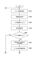
- step S501 the CPU 44a acquires a stereo image taken by the camera unit 11.
- step S502 the CPU 44a acquires a distance image based on the stereo image.
- step S503 the CPU 44a crops one image of the first camera 11a or the second camera 11b constituting the camera unit 11. In this embodiment, the image of the second camera 11b is used.
- step S504 the CPU 44a executes the object recognition process using the cropped image.
- the features of an object including a person and a marker are learned in advance by machine learning, and the object is recognized by comparing it with the learning result.
- step S505 the CPU 44a determines whether or not the marker has been recognized as a result of the object recognition process in step S504. If it is determined that the marker has been recognized, the process proceeds to step S506. On the other hand, if it is determined that the marker is not recognized, the process proceeds to step S517.
- step S506 the CPU 44a acquires the position of the center of gravity of the marker in the image.
- the center of gravity position for example, a specific position of the marker is specified as the center of gravity position based on the information of the center of gravity position of the marker held in advance.
- the position of the center of gravity is just an example, and is not limited to the position of the center of gravity. It may be the position of the top of the marker, or it may be the ground contact position where the marker and the ground are in contact with each other.
- step S507 the CPU 44a acquires distance information from the work vehicle 10 to the position of the center of gravity of the marker as marker information using the distance image acquired in step S502.
- step S508 the CPU 44a determines whether or not there are a plurality of markers recognized in step S505. If a plurality of markers are recognized, the process proceeds to step S509. On the other hand, if a single marker is recognized, the process proceeds to step S515.
- step S509 the CPU 44a determines whether or not the two markers included in the plurality of markers are adjacent markers. In the present embodiment, it is determined whether or not the distance between the two markers is within the predetermined distance range, and when the distance is within the predetermined distance range, it is determined that the markers are adjacent to each other. In the present embodiment, it is assumed that the markers are installed at intervals of 3 m, but the markers are not always arranged at equal intervals of 3 m, and there is a possibility that some deviation occurs. If the range is, for example, 2.5 m to 3.5 m, it is determined that the markers are adjacent to each other. If it is determined that the markers are adjacent to each other, the process proceeds to step S510.
- step S511 As a method for determining whether or not the markers are adjacent to each other, another determination method described with reference to FIGS. 4A to 4G may be used.
- step S510 the CPU 44a sets a virtual line between two markers determined to be adjacent markers.
- step S511 the CPU 44a determines whether or not the determination has been completed for all combinations of the two markers among the plurality of markers. When the determination is completed for all the combinations, the process proceeds to step S512. On the other hand, if there is a combination that has not been determined yet, the process returns to step S509 and a determination is made for a new combination of the two markers.
- step S512 the CPU 44a determines the distance from the work vehicle 10 to the virtual line located ahead of the work vehicle 10 in the traveling direction based on the traveling direction of the work vehicle 10 and the virtual line located ahead of the traveling direction. Is calculated. In the example of FIG. 4A, the distance to the intersection with the virtual line 411 located ahead of the traveling direction 402 is calculated.
- the point O is the current position of the work vehicle 10.
- Point A corresponds to marker 401a in FIG. 4A
- point B corresponds to marker 401b in FIG. 4A.
- the distance to be obtained is X
- X is the length of the line OC.
- the length of the line OA and the length of the line OB can be obtained from the distance image.
- the angle ⁇ and the angle ⁇ can also be obtained from the shooting direction (usually the same direction as the traveling direction 402) and the viewing angle of the camera unit 11 and the directions of the points A and B.
- AD: BE CD: CE.
- the ratio of AD to BE is the ratio of the distances from the center line 701 of the image of one camera captured by the camera unit 11 (that is, AG and BH), as shown in FIG. 7, which represents an example of the captured image. It can be obtained by the ratio of the lengths of.
- AD OAsin ⁇
- BE OBsin ⁇
- CD OC-OAcos ⁇
- CE OBcos ⁇ -OC.
- the distance X to the point C can be obtained as.
- step S513 the CPU 44a determines whether or not the distance from the work vehicle 10 to the virtual line located ahead of the work vehicle 10 in the traveling direction is equal to or less than a threshold value (for example, 0.1 m). If it is determined that the distance is equal to or less than the threshold value, the process proceeds to S514. On the other hand, if the distance is larger than the threshold value, the process proceeds to step S517.
- a threshold value for example, 0.1 m
- step S514 the CPU 44a executes an avoidance operation based on the virtual line. Specifically, when the work vehicle 10 approaches a threshold value (for example, 0.1 m) from the virtual line, it stops, retreats, or turns. As a result, it is possible to prevent the work vehicle 10 from deviating to an area deeper than the virtual line. For example, the work vehicle 10 does not deviate to the inner region beyond the intersection position of the virtual line 411 existing in the traveling direction 415 shown in FIG. 4A and the line 415 extending in the traveling direction 415. When the distance from to the virtual line 415 is equal to or less than the threshold value, the work vehicle 10 is stopped, retreated, or turned.
- a threshold value for example, 0.1 m
- turning means changing the traveling direction of the work vehicle 10, moving along a parabolic trajectory when viewed from above the site, and rotating and traveling on the spot after stopping at a certain point. It also includes changing direction and then proceeding, and wrapping around so as not to enter the area partitioned by the virtual line.
- the running speed of the work vehicle 10 toward the virtual line 415 may be further controlled to be decelerated.
- decelerating in advance before performing an avoidance operation such as stopping, retreating, or turning it is possible to suppress a sudden operation such as a sudden stop, a sudden retreat from a sudden stop, or a sudden turn.
- step S515 the CPU 44a determines whether or not the distance from the work vehicle 10 to the marker is equal to or less than the threshold value.
- the threshold value here is, for example, 0.5 m, but is not limited to this value. If it is determined that the distance is equal to or less than the threshold value, the process proceeds to S516. On the other hand, if the distance is larger than the threshold value, the process proceeds to step S517.
- step S516 the CPU 44a executes an avoidance operation. Specifically, when the work vehicle 10 approaches a threshold distance (for example, 0.5 m) from the marker, it stops, retreats, or turns. Since only one marker is detected, the avoidance operation is an avoidance operation performed regardless of the virtual line. After that, the process proceeds to step S517.
- a threshold distance for example, 0.5 m
- step S517 the CPU 44a determines whether or not to end a series of processes. For example, when the remaining battery level falls below the threshold value and it becomes necessary to return to the charging station 300, when a predetermined time has elapsed from the start of work, and further, the work in the work area is completed (for example, the work area). For example, when you have finished mowing the lawn inside. This also applies when the user turns off the power of the work vehicle 10. If it is determined that the series of processes is not completed, the process returns to step S501. On the other hand, when it is determined that the series of processes is completed, the processes of FIGS. 5A and 5B are terminated.
- the avoidance operation is executed so that the work vehicle does not deviate to the inner area beyond the virtual line.
- This makes it possible to control the work machine using the same type of markers, and it is not necessary to prepare markers having different characteristics so that each of the plurality of markers can be distinguished. Therefore, it is possible to reduce the introduction cost of the marker.
- the virtual line virtual wire
- the work area may be defined by combining the existing area wire and the marker.
- the markers can be freely arranged, the shape of the work area can be flexibly changed. For example, when the user himself works on a part of the garden, he / she may not want the work vehicle to enter the area. In that case, by defining the area to be surrounded by a marker, it is possible to easily create an area where the work vehicle does not enter temporarily.
- the CPU 44a sets a travel route of the work vehicle 10 and travels according to the set travel route. To do. At that time, the travel route is set so that the virtual line does not exist on the travel route. As a result, it is possible to prevent the vehicle from deviating from the virtual line and traveling.
- step S511 an example of performing processing considering a combination of two markers for all the detected markers has been described, but based on the traveling direction of the work vehicle 10, the left and right sides of the line along the traveling direction have been described. It may be a target for processing certain markers.
- FIG. 4A not all combinations (6 ways) of the four markers of the markers 401a to 401d are processed, but only the markers on the left and right of the line 415 along the traveling direction 415 are processed. May be.
- three markers 401a and 401b, a marker 401a, a marker 401c, a marker 401a and a marker 401d are targeted for processing, and three markers 401b and a marker 401c, a marker 401b and a marker 401d, and a marker 401c and a marker 401d are processed. It may be excluded from the processing target. This makes it possible to speed up the processing.
- step S513 when the distance from the work vehicle 10 to the virtual line is larger than the threshold value in step S513, an example of returning to step S501 through step S517 and acquiring a stereo image again has been described.
- the plurality of markers may not be detected as the work vehicle 10 advances and approaches the virtual line. Therefore, instead of necessarily returning to step S501 and taking a picture again, the timing at which the distance from the work vehicle 10 to the virtual line becomes equal to or less than the threshold value is estimated based on the traveling speed of the work vehicle 10, and that timing has arrived. Then, it may be controlled to execute the avoidance operation.
- the distance from a certain point to the virtual line is calculated, and then the distance traveled from the point is constantly measured by an odometry, an inertial measurement unit (IMU), or the like. Then, the operation of the work vehicle 10 may be controlled based on the calculated distance and the moving distance during measurement. For example, the avoidance operation may be executed when the moving distance during measurement reaches the “distance from the relevant point to the virtual line”.
- IMU inertial measurement unit
- steps S512 and S513 an example of controlling the avoidance operation based on the distance between the work vehicle 10 and the virtual line has been described, but the distance is not limited.
- the time required for the work vehicle 10 to reach the virtual line 411 may be calculated, and it may be determined whether or not the work vehicle 10 has reached the virtual line based on the time.
- the time may be calculated based on the traveling speed of the work vehicle 10 and the distance from the work vehicle 10 to the virtual line 411. Then, when the difference between the time and the elapsed time becomes equal to or less than the threshold value, the avoidance operation may be controlled to be executed.
- step S515 an example of controlling the avoidance operation based on the distance between the work vehicle 10 and the marker has been described, but the distance is not limited.
- the time required for the work vehicle 10 to reach the marker may be calculated, and it may be determined whether or not the work vehicle 10 has reached the marker based on the time.
- step S501 it may be controlled to separately execute the avoidance operation when the timing when the distance from the work vehicle 10 to the virtual line becomes equal to or less than the threshold value arrives.
- the distance information to the detected marker is acquired as the marker information, and the distance from the work vehicle to the virtual line and the time until the work vehicle reaches the virtual line are calculated using the distance information.
- the marker position information indicating the position coordinates of the marker is acquired as the marker information, and the marker position information and the self-position information and the orientation information of the work vehicle are used from the work vehicle. An example of performing the avoidance operation by calculating the distance to the virtual line and the time until the work vehicle reaches the virtual line will be described.
- the work vehicle 10 according to the present embodiment sets a virtual line between the markers and controls the work vehicle 10 so as not to deviate to an area deeper than the virtual line.
- the same reference numerals are given to the steps for performing the same processing as the flowcharts of FIGS. 5A and 5B.
- the differences from FIGS. 5A and 5B will be mainly described.
- step S801 the CPU 44a acquires information on its own position and direction using the GPS sensor 48 and the direction sensor 46.
- step S802 the CPU 44a acquires the marker position information (position coordinates) of the detected marker as the marker information.
- the marker position information is stored in the memory 44c in advance as map information so that it can be referred to, for example, as described with reference to FIG. 4D in the first embodiment.
- the work vehicle 10 recognizes its own position and direction using the GPS sensor 48 and the direction sensor 46, and determines which marker included in the map information is the marker detected from the image taken by the camera unit 11. Acquire the marker position information of the identified and detected marker.
- the marker position information from the landscape information of the image taken by the camera unit 11.
- the landscape information and the marker included in the image and the distance information to the marker whose distance was measured at the time of the landscape are stored in association with each other in advance.
- the work vehicle 10 is running in the work area, it is associated with each other at various places and stored as learning information.
- the position coordinates of the marker detected from the image taken by the camera unit 11 can be obtained by using the self-position and the direction recognized by using the GPS sensor 48 and the direction sensor 46. , Can be acquired as marker position information.
- the work vehicle 10 recognizes its own position and direction by using the GPS sensor 48 and the direction sensor 46, and also obtains the distance information (distance image) from the image taken by the camera unit 11 to the detected marker. Acquired based on images with parallax (S501 and S502). Further, the angle at which the marker exists with respect to the shooting direction of the camera unit 11 (for example, the angle ⁇ and the angle ⁇ in FIG. 6) is obtained from the position of the marker with respect to the center of the captured image. Then, the direction in which the marker exists is specified from the direction of the work vehicle 10 and the obtained angle, and the position coordinates ahead of the distance indicated by the acquired distance information along the direction are acquired as the marker position information. You may.
- step S803 the CPU 44a determines whether or not the two markers included in the plurality of markers are adjacent markers. Since the determination method is the same as that of the first embodiment in the present embodiment as well, detailed description thereof will be omitted.
- step S804 the CPU 44a determines the distance from the work vehicle 10 to the virtual line located ahead of the work vehicle 10 in the traveling direction based on the traveling direction of the work vehicle 10 and the virtual line located ahead of the traveling direction. Is calculated. In the example of FIG. 4A, the distance to the intersection with the virtual line 411 located ahead of the traveling direction 402 is calculated.
- the point O is the current position of the work vehicle 10.
- Point A corresponds to marker 401a in FIG. 4A
- point B corresponds to marker 401b in FIG. 4A.
- the distance to be obtained is X
- X is the length of the line OC.
- the length of the line OA and the length of the line OB can be obtained from the position coordinates of the point A, the position coordinates of the point B, and the position coordinates (self-position) of the point O because they are known.
- the distance from the work vehicle 10 to the virtual line 411 located ahead in the traveling direction of the work vehicle 10 is calculated by the same procedure as the procedure described in the first embodiment.
- the marker position information indicating the position coordinates of the marker is acquired as the marker information, and the work vehicle uses the marker position information and the self-position information and the orientation information of the work vehicle.
- the avoidance operation is performed by calculating the distance from the to the virtual line and the time until the work vehicle reaches the virtual line.
- the work vehicle 10 acquires distance information from the image taken by the camera unit 11 to the detected marker while acquiring information on its own position and direction using the GPS sensor 48 and the direction sensor 46.
- the distance to the marker can be acquired based on an image having parallax.
- the angle at which the marker exists with respect to the shooting direction of the camera unit 11 (for example, the angle ⁇ and the angle ⁇ in FIG. 6) is obtained from the position of the marker with respect to the image center of the captured image as shown in FIG.
- the direction in which the marker exists is specified from the direction of the work vehicle 10 and the obtained angle, and the position coordinates ahead by the distance indicated by the acquired distance information are acquired as the marker position information along the direction. ..
- the work vehicle 10 uses the information of its own position and direction, the distance information to the marker, and the direction in which the marker exists to obtain the position information (position coordinates) of the marker. calculate. Then, the calculated position information of the marker is plotted on the map. As a result, it is possible to create map information including the position information of the markers arranged to define the work area.
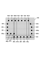
- FIG. 9 is an example of a map on which the position information of the markers is plotted.
- Reference numeral 901 is a map, which is defined as a grid area divided in a grid pattern.
- Reference numerals 901a to 901w are position information of the plotted markers.
- the work vehicle 10 creates such map information and stores it as a map database while performing the work or traveling before the start of the work.
- the created map information may be presented to the user.
- the work vehicle 10 may transmit map information to a communication terminal (for example, a tablet, a smartphone, etc.) possessed by the user and present the map information on the display screen of the communication terminal.
- a communication terminal for example, a tablet, a smartphone, etc.
- map information including the marker positions arranged to define the work area is created and presented to the user. This allows the user to obtain map information about the manually placed markers. Therefore, it is possible to manually adjust the placement position of the marker later to redefine a more appropriate work area.
- processing of the present embodiment may be performed in parallel with the first or second embodiment, or may be independently performed independently of these.
- at least one of the virtual line information acquired by the processing of the first embodiment and the second embodiment and the position information of the marker acquired by the processing of the third embodiment is reflected in the map information, and the map information is reflected. May be presented to the user.
- the lawn mower has been described as an example of the autonomous work machine, but the description is not limited to the lawn mower.
- the present invention can be applied to other types of autonomous work machines such as autonomous snow blowers, golf ball recovery machines, and outboard motors.
- the autonomous working machine (for example, 10) of the above embodiment is An autonomous work machine that works in the work area Detection means (for example, 11, 44a) for detecting a plurality of markers (for example, 401a to 401n) arranged to define the work area, and Specific means (for example, 44a) for specifying marker information based on the detection result of the detection means, and A setting means (for example, 44a) for setting a virtual line (for example, 411, 412, 413) connecting the plurality of markers based on the marker information specified by the specific means.
- a control means for example, 44a) that controls the autonomous work machine so that the autonomous work machine does not deviate to an area deeper than the virtual line set by the setting means. To be equipped.
- the control means calculates the time required for the autonomous work machine to reach the virtual line, and controls the autonomous work machine based on the calculated time.
- the control means calculates the time based on the speed of the autonomous work machine and the distance from the autonomous work machine to the virtual line.
- the control means For example, IMU, odometry for measuring the moving distance of the autonomous work machine, The control means The distance from the autonomous work machine to the virtual line is calculated based on the marker information. The autonomous work machine is controlled based on the calculated distance and the movement distance from the position of the autonomous work machine for which the distance is calculated.
- a measuring means for example, IMU, odometry
- the marker information includes distance information indicating a distance from the autonomous work machine to the marker.
- the setting means sets the virtual line based on the distance information.
- the virtual line is set using the distance information indicating the distance to the marker, it is possible to set the virtual line even if the position information of the marker is not known.
- the marker information includes marker position information indicating the position coordinates of the marker.
- the setting means sets the virtual line based on the marker position information.
- the virtual line is set using the marker position information, it is possible to set the virtual line without separately acquiring the distance information to the marker.
- the specific means identifies the marker information based on the characteristic information of the marker stored in the storage means and the characteristics of the marker detected by the detection means.
- the control means stops, moves backward, or turns the autonomous work machine.
- the control means decelerates the autonomous work machine toward the virtual line.
- a sudden operation such as a sudden stop, a sudden retreat from a sudden stop, or a sudden turn is performed. Can be suppressed.
- An adjacent marker identifying means for example, 44a for identifying two markers from the plurality of markers detected by the detecting means as adjacent markers is further provided.
- the control means sets a virtual line between the two markers specified as the adjacent markers by the adjacent marker specifying means.
- the adjacent marker identifying means identifies two markers whose distances between the markers are within a predetermined distance range as the adjacent markers.
- the adjacent marker identifying means has the two. It is specified that the marker is not the adjacent marker.
- Each marker has an index (eg, 431, 432) that indicates the direction in which adjacent markers are present.
- the adjacent marker identifying means identifies a second marker (for example, 431 or 432) existing in the direction indicated by the index of the first marker (for example, 401 m) as the adjacent marker.
- an acquisition means for acquiring locus information of the autonomous work machine for example, a locus along an arrow in FIG. 4C
- the adjacent marker identifying means identifies two markers consistent with the locus information as the adjacent markers among the plurality of markers.
- the adjacent marker specifying means identifies two markers consistent with the boundary information as the adjacent markers among the plurality of markers.
- the boundary information is arrangement information (for example, 476) of a plurality of markers arranged at the boundary of the work area, or information on a boundary line indicating the boundary of the work area (for example, 475).
- the plurality of markers include a plurality of first-type markers (for example, 483) that define the outer edge of the work area, and a plurality of markers that define an internal area included in the outer edge and excluded from the work area. Includes a second type of marker (eg 484)
- the adjacent marker identifying means identifies the first type of marker and the second type of marker as not being the adjacent marker.
- the plurality of markers include a plurality of markers of the first type (for example, 491a to 491e) arranged at a first distance interval, and a plurality of markers arranged at a second distance interval shorter than the first distance interval. Includes a second type of marker (eg, 492a-492f) and When the second type of marker is present between the two first type markers among the plurality of first type markers, the adjacent marker identifying means is the two first type markers. A type of marker is specified as the adjacent marker.
- the route setting means sets the travel route so that the virtual line does not exist on the travel route.
- the traveling route is a traveling route for returning to the station.
- control means controls the autonomous work machine based on the information of the virtual line and the current position of the autonomous work machine specified by the position specifying means.
- the control means reflects at least one of the marker position information (for example, 901a to 901w) and the information of the virtual line in the map information (for example, 900) of the work area.
- map information that reflects marker position information and virtual line information.
- the control means presents to the user the map information in which at least one of the marker position information and the virtual line information is reflected.
- the user can recognize the created map information.
- the control means transmits the map information reflecting at least one of the marker position information and the virtual line information to the user's communication terminal (for example, 470).
- the control method of the autonomous working machine (for example, 10) of the above embodiment is It is a control method for autonomous work machines that work in the work area.
- a detection step that detects a plurality of markers arranged to define the work area, and A specific step of specifying marker information based on the detection result in the detection step, and A setting step of setting a virtual line connecting the plurality of markers based on the marker information specified in the specific step, and a setting step.
- the program of the above embodiment It is a program for making a computer function as an autonomous work machine of the said embodiment.
- the autonomous working machine according to the present invention can be realized by a computer.
Abstract
An autonomous work machine that performs work within a work area, said autonomous work machine being provided with: a detection means which detects a plurality of markers arranged to define the work area; an identification means which identifies marker information on the basis of the detection results from the detection means; a setting means which sets a virtual line connecting the plurality of markers, on the basis of the marker information identified by the identification means; and a control means which controls the autonomous work machine such that the autonomous work machine does not enter into any regions beyond the virtual line set by the setting means.
Description
本発明は、自律作業機、自律作業機の制御方法及びプログラムに関するものである。
The present invention relates to an autonomous work machine, a control method and a program of the autonomous work machine.
特許文献1は、マーカを認識したら、ロボット車両に格納されたマーカの位置情報を読み出して、ロボット車両の現在位置を把握することを開示している。
Patent Document 1 discloses that when a marker is recognized, the position information of the marker stored in the robot vehicle is read out to grasp the current position of the robot vehicle.
しかしながら、特許文献1に記載の技術では、複数のマーカのそれぞれが区別可能な異なるマーカを用意する必要があり、マーカの調達コストが増大するという課題がある。
However, in the technique described in Patent Document 1, it is necessary to prepare different markers that can distinguish each of the plurality of markers, and there is a problem that the procurement cost of the markers increases.
本発明は、上記課題の認識を契機として為されたものであり、個々に区別することが不要なマーカを使用して作業機を制御するための技術を提供することを目的とする。
The present invention has been made with the recognition of the above problems as an opportunity, and an object of the present invention is to provide a technique for controlling a working machine by using markers that do not need to be individually distinguished.
上記課題を解決し、目的を達成するために、本発明に係る自律作業機は、
作業エリア内で作業する自律作業機であって、
前記作業エリアを規定するために配置された複数のマーカを検出する検出手段と、
前記検出手段の検出結果に基づいてマーカ情報を特定する特定手段と、
前記特定手段により特定された前記マーカ情報に基づいて前記複数のマーカを結ぶ仮想ラインを設定する設定手段と、
前記設定手段により設定された前記仮想ラインよりも奥の領域へ前記自律作業機が逸脱しないように前記自律作業機を制御する制御手段と、
を備えることを特徴とする。 In order to solve the above problems and achieve the object, the autonomous working machine according to the present invention
An autonomous work machine that works in the work area
A detection means for detecting a plurality of markers arranged to define the work area, and
Specific means for specifying marker information based on the detection result of the detection means, and
A setting means for setting a virtual line connecting the plurality of markers based on the marker information specified by the specific means, and
A control means for controlling the autonomous work machine so that the autonomous work machine does not deviate to an area deeper than the virtual line set by the setting means.
It is characterized by having.
本発明によれば、個々に区別することが不要なマーカを使用して作業機を制御することが可能となる。
According to the present invention, it is possible to control the working machine by using markers that do not need to be individually distinguished.
本発明のその他の特徴及び利点は、添付図面を参照とした以下の説明により明らかになるであろう。なお、添付図面においては、同じ若しくは同様の構成には、同じ参照番号を付す。
Other features and advantages of the present invention will be clarified by the following description with reference to the accompanying drawings. In the attached drawings, the same or similar configurations are given the same reference numbers.
添付図面は明細書に含まれ、その一部を構成し、本発明の実施の形態を示し、その記述と共に本発明の原理を説明するために用いられる。
本発明の一実施形態に係る自律走行可能な作業機の外観図である。
本発明の一実施形態に係る作業機を側方から観察した図である。
本発明の一実施形態に係る制御システムの構成例を示す図である。
本発明の一実施形態に係る仮想ラインの設定方法及び隣接マーカの判定方法の説明図である。
本発明の一実施形態に係る隣接マーカの判定方法の説明図である。
本発明の一実施形態に係る隣接マーカの判定方法の説明図である。
本発明の一実施形態に係る隣接マーカの判定方法の説明図である。
本発明の一実施形態に係る隣接マーカの判定方法の説明図である。
本発明の一実施形態に係る隣接マーカの判定方法の説明図である。
本発明の一実施形態に係る隣接マーカの判定方法の説明図である。
実施形態1に係る自律作業機が実施する処理手順を示すフローチャートである。
実施形態1に係る自律作業機が実施する処理手順を示すフローチャートである。
本発明の一実施形態に係る仮想ラインまでの距離の求め方の説明図である。
本発明の一実施形態に係る撮影画像の一例を示す図である。
実施形態2に係る自律作業機が実施する処理手順を示すフローチャートである。
実施形態2に係る自律作業機が実施する処理手順を示すフローチャートである。
実施形態3に係るマーカ位置をプロットした地図情報の一例を示す図である。
The accompanying drawings are included in the specification and are used to form a part thereof, show embodiments of the present invention, and explain the principles of the present invention together with the description thereof.
It is an external view of the work machine capable of autonomous traveling which concerns on one Embodiment of this invention. It is a figure which observed the working machine which concerns on one Embodiment of this invention from the side. It is a figure which shows the structural example of the control system which concerns on one Embodiment of this invention. It is explanatory drawing of the setting method of the virtual line and the determination method of the adjacent marker which concerns on one Embodiment of this invention. It is explanatory drawing of the determination method of the adjacent marker which concerns on one Embodiment of this invention. It is explanatory drawing of the determination method of the adjacent marker which concerns on one Embodiment of this invention. It is explanatory drawing of the determination method of the adjacent marker which concerns on one Embodiment of this invention. It is explanatory drawing of the determination method of the adjacent marker which concerns on one Embodiment of this invention. It is explanatory drawing of the determination method of the adjacent marker which concerns on one Embodiment of this invention. It is explanatory drawing of the determination method of the adjacent marker which concerns on one Embodiment of this invention. It is a flowchart which shows the processing procedure which the autonomous work machine which concerns on Embodiment 1 carry out. It is a flowchart which shows the processing procedure which the autonomous work machine which concerns on Embodiment 1 carry out. It is explanatory drawing of the method of obtaining the distance to a virtual line which concerns on one Embodiment of this invention. It is a figure which shows an example of the photographed image which concerns on one Embodiment of this invention. It is a flowchart which shows the processing procedure which the autonomous work machine which concerns on Embodiment 2 carry out. It is a flowchart which shows the processing procedure which the autonomous work machine which concerns on Embodiment 2 carry out. It is a figure which shows an example of the map information which plotted the marker position which concerns on Embodiment 3.
以下、添付の図面を参照しながら、本発明の実施形態を説明する。なお、各図面を通じて同一の構成要素に対しては同一の参照符号を付している。
Hereinafter, embodiments of the present invention will be described with reference to the accompanying drawings. The same reference numerals are given to the same components throughout the drawings.
(実施形態1)
図1は、本発明の一実施形態に係る自律走行可能な自律作業機の外観図である。以下では側面視における自律作業機の進行方向(車長方向)と、進行方向に直交する横方向(車幅方向)と、進行方向と横方向に直交する鉛直方向とを、それぞれ前後方向、左右方向、上下方向と定義し、それに従って各部の構成を説明する。 (Embodiment 1)
FIG. 1 is an external view of an autonomous working machine capable of autonomous traveling according to an embodiment of the present invention. In the following, the traveling direction (vehicle length direction) of the autonomous work equipment in the side view, the lateral direction (vehicle width direction) orthogonal to the traveling direction, and the vertical direction orthogonal to the traveling direction and the lateral direction are shown in the front-rear direction and the left-right direction, respectively. The direction and the vertical direction are defined, and the configuration of each part is explained accordingly.
<自律作業機の構成>
図1において、符号10は自律作業機(以下「作業車」という)を示す。作業車10は、具体的には自律走行する芝刈機として機能する。但し、芝刈機は一例であり、他の種類の作業機械にも本発明を適用することができる。作業車10は、複数のカメラ(第1のカメラ11a、第2のカメラ11b)を含むカメラユニット11を備えており、視差ある第1のカメラ11a、第2のカメラ11bにより撮影された画像を用いて、前方に存在する物体と、作業車10との距離情報を算出して取得する。そして、撮影された画像と、予め保持されている物体認識モデルとに基づいて、作業車10の動作を制御する。 <Configuration of autonomous work machine>
In FIG. 1,reference numeral 10 indicates an autonomous work machine (hereinafter referred to as “work vehicle”). Specifically, the work vehicle 10 functions as a lawnmower that travels autonomously. However, the lawnmower is an example, and the present invention can be applied to other types of work machines. The work vehicle 10 includes a camera unit 11 including a plurality of cameras (first camera 11a, second camera 11b), and captures images taken by the first camera 11a and the second camera 11b having parallax. It is used to calculate and acquire distance information between an object existing in front and the work vehicle 10. Then, the operation of the work vehicle 10 is controlled based on the captured image and the object recognition model held in advance.
図1において、符号10は自律作業機(以下「作業車」という)を示す。作業車10は、具体的には自律走行する芝刈機として機能する。但し、芝刈機は一例であり、他の種類の作業機械にも本発明を適用することができる。作業車10は、複数のカメラ(第1のカメラ11a、第2のカメラ11b)を含むカメラユニット11を備えており、視差ある第1のカメラ11a、第2のカメラ11bにより撮影された画像を用いて、前方に存在する物体と、作業車10との距離情報を算出して取得する。そして、撮影された画像と、予め保持されている物体認識モデルとに基づいて、作業車10の動作を制御する。 <Configuration of autonomous work machine>
In FIG. 1,
図2は、該作業車10を横方向(車幅方向)から観察した図である。図2に示されるように、作業車10は、カメラユニット11、車体12、ステー13、前輪14、後輪16、ブレード20、作業モータ22、モータ保持部材23、ブレード高さ調節モータ100、及び並進機構101を備えている。また、作業車10は、走行モータ26、各種のセンサ群S、電子制御ユニット(ECU:Electronic Control Unit)44、充電ユニット30、電池(バッテリ)32、充電端子34、通信部35を備えている。
FIG. 2 is a view of the work vehicle 10 observed from the lateral direction (vehicle width direction). As shown in FIG. 2, the work vehicle 10 includes a camera unit 11, a vehicle body 12, a stay 13, a front wheel 14, a rear wheel 16, a blade 20, a work motor 22, a motor holding member 23, a blade height adjusting motor 100, and a blade height adjusting motor 100. The translation mechanism 101 is provided. Further, the work vehicle 10 includes a traveling motor 26, various sensor groups S, an electronic control unit (ECU: Electronic Control Unit) 44, a charging unit 30, a battery (battery) 32, a charging terminal 34, and a communication unit 35. ..
作業車10の車体12は、シャーシ12aと、該シャーシ12aに取り付けられるフレーム12bとを有する。前輪14は、前後方向においてシャーシ12aの前側にステー13を介して固定される小径の左右2個の車輪である。後輪16は、シャーシ12aの後側に取り付けられる大径の左右2個の車輪である。
The vehicle body 12 of the work vehicle 10 has a chassis 12a and a frame 12b attached to the chassis 12a. The front wheels 14 are two small-diameter left and right wheels fixed to the front side of the chassis 12a via a stay 13 in the front-rear direction. The rear wheels 16 are two large-diameter left and right wheels attached to the rear side of the chassis 12a.
ブレード20は、シャーシ12aの中央位置付近に取り付けられる芝刈り作業用のロータリブレードである。作業モータ22は、ブレード20の上方に配置された電動モータである。ブレード20は、作業モータ22と接続されており、作業モータ22によって回転駆動される。モータ保持部材23は、作業モータ22を保持する。モータ保持部材23は、シャーシ12aに対して回転が規制されると共に、例えば、ガイドレールと、ガイドレールに案内されて上下に移動可能なスライダとの組み合せにより、上下方向の移動が許容されている。
The blade 20 is a rotary blade for lawn mowing work that is attached near the center position of the chassis 12a. The work motor 22 is an electric motor arranged above the blade 20. The blade 20 is connected to the work motor 22 and is rotationally driven by the work motor 22. The motor holding member 23 holds the working motor 22. The rotation of the motor holding member 23 is restricted with respect to the chassis 12a, and the motor holding member 23 is allowed to move in the vertical direction by, for example, a combination of a guide rail and a slider that is guided by the guide rail and can move up and down. ..
ブレード高さ調節モータ100は、接地面GRに対するブレード20の上下方向の高さを調節するためのモータである。並進機構101は、ブレード高さ調節モータ100と接続されており、ブレード高さ調節モータ100の回転を上下方向の並進移動に変換するための機構である。当該並進機構101は、作業モータ22を保持するモータ保持部材23とも接続されている。
The blade height adjusting motor 100 is a motor for adjusting the height of the blade 20 in the vertical direction with respect to the ground plane GR. The translation mechanism 101 is connected to the blade height adjusting motor 100, and is a mechanism for converting the rotation of the blade height adjusting motor 100 into translational movement in the vertical direction. The translation mechanism 101 is also connected to a motor holding member 23 that holds the work motor 22.
ブレード高さ調節モータ100の回転が並進機構101により並進移動(上下方向の移動)に変換され、並進移動はモータ保持部材23に伝達される。モータ保持部材23の並進移動(上下方向の移動)により、モータ保持部材23に保持されている作業モータ22も並進移動(上下方向の移動)する。作業モータ22の上下方向の移動により、接地面GRに対するブレード20の高さを調節することができる。
The rotation of the blade height adjusting motor 100 is converted into translational movement (movement in the vertical direction) by the translation mechanism 101, and the translational movement is transmitted to the motor holding member 23. Due to the translational movement (movement in the vertical direction) of the motor holding member 23, the work motor 22 held by the motor holding member 23 also moves in translation (movement in the vertical direction). The height of the blade 20 with respect to the ground plane GR can be adjusted by moving the work motor 22 in the vertical direction.
走行モータ26は、作業車10のシャーシ12aに取り付けられている2個の電動モータ(原動機)である。2個の電動モータは、左右の後輪16とそれぞれ接続されている。前輪14を従動輪、後輪16を駆動輪として左右の車輪を独立に正転(前進方向への回転)あるいは逆転(後進方向への回転)させることで、作業車10を種々の方向に移動させることができる。
The traveling motor 26 is two electric motors (motors) attached to the chassis 12a of the work vehicle 10. The two electric motors are connected to the left and right rear wheels 16, respectively. The work vehicle 10 can be moved in various directions by independently rotating the left and right wheels forward (rotating in the forward direction) or reversing (rotating in the backward direction) with the front wheels 14 as the trailing wheels and the rear wheels 16 as the driving wheels. Can be made to.
充電端子34は、フレーム12bの前後方向の前端位置に設けられた充電端子であり、充電ステーション(例えば、図3を参照して後述する充電ステーション300)の対応する端子と接続することで、充電ステーションからの給電を受けることができる。充電端子34は、配線を介して充電ユニット30と接続されており、当該充電ユニット30は電池(バッテリ)32と接続されている。また、作業モータ22、走行モータ26、ブレード高さ調節モータ100も電池32と接続されており、電池32から給電されるように構成されている。
The charging terminal 34 is a charging terminal provided at a front end position in the front-rear direction of the frame 12b, and can be charged by connecting to a corresponding terminal of a charging station (for example, a charging station 300 described later with reference to FIG. 3). You can receive power from the station. The charging terminal 34 is connected to the charging unit 30 via wiring, and the charging unit 30 is connected to the battery 32. Further, the work motor 22, the traveling motor 26, and the blade height adjusting motor 100 are also connected to the battery 32, and are configured to be supplied with power from the battery 32.
ECU44は、回路基板上に構成されたマイクロコンピュータを含む電子制御ユニットであり、作業車10の動作を制御する。ECU44の詳細は後述する。通信部35は、作業車10と有線又は無線で接続された外部機器(例えば、後述する充電ステーションや、ユーザが所持する通信端末、作業車10を操作するためのリモートコントローラなど)に対して情報を送受信することができる。
The ECU 44 is an electronic control unit including a microcomputer configured on a circuit board, and controls the operation of the work vehicle 10. Details of the ECU 44 will be described later. The communication unit 35 provides information to an external device (for example, a charging station described later, a communication terminal owned by the user, a remote controller for operating the work vehicle 10, etc.) connected to the work vehicle 10 by wire or wirelessly. Can be sent and received.
図3は、本発明の一実施形態に係る制御システムの構成例を示す図である。制御システム1は、作業車10と、充電ステーション300とを含んで構成されている。なお、後述するユーザが所持する通信端末や作業車10を操作するためのリモートコントローラをさらに含んでもよい。
FIG. 3 is a diagram showing a configuration example of a control system according to an embodiment of the present invention. The control system 1 includes a work vehicle 10 and a charging station 300. It should be noted that a remote controller for operating a communication terminal or a work vehicle 10 owned by a user, which will be described later, may be further included.
図3に示されるように、作業車10が備えるECU44は、CPU44aと、I/O44bと、メモリ44cとを備えている。I/O44bは、各種情報の入出力を行う。メモリ44cは、ROM(Read Only Memory)、EEPROM(Electrically Erasable Programmable Read Only Memory)、RAM(Random Access Memory)等である。メモリ44cには、撮影画像、作業車10の作業日程、作業エリアに関する地図情報や、作業車10の動作を制御するための各種プログラムなどが記憶されている。ECU44は、メモリ44cに格納されているプログラムを読み出して実行することにより、本発明を実現するための各処理部として動作することができる。
As shown in FIG. 3, the ECU 44 included in the work vehicle 10 includes a CPU 44a, an I / O 44b, and a memory 44c. The I / O 44b inputs / outputs various information. The memory 44c is a ROM (Read Only Memory), an EEPROM (Electrically Erasable Programmable Read Only Memory), a RAM (Random Access Memory), or the like. In the memory 44c, a photographed image, a work schedule of the work vehicle 10, map information regarding the work area, various programs for controlling the operation of the work vehicle 10, and the like are stored. The ECU 44 can operate as each processing unit for realizing the present invention by reading and executing the program stored in the memory 44c.
ECU44は各種のセンサ群Sと接続されている。センサ群Sは、方位センサ46、GPSセンサ48、車輪速センサ50、角速度センサ52、加速度センサ54、電流センサ62、及びブレード高さセンサ64を含んで構成されている。
The ECU 44 is connected to various sensor groups S. The sensor group S includes an orientation sensor 46, a GPS sensor 48, a wheel speed sensor 50, an angular speed sensor 52, an acceleration sensor 54, a current sensor 62, and a blade height sensor 64.
方位センサ46及びGPSセンサ48は、作業車10の向きや位置の情報を取得するためのセンサである。方位センサ46は、地磁気に応じた方位を検出する。GPSセンサ48は、GPS衛星からの電波を受信して作業車10の現在位置(緯度、経度)を示す情報を検出する。なお、GPSセンサ48及び方位センサ46に加えて、或いは、これらに代えて、オドメトリ、慣性計測装置(IMU:Inertial Measurement Unit)を備えていてもよい。
The orientation sensor 46 and the GPS sensor 48 are sensors for acquiring information on the orientation and position of the work vehicle 10. The azimuth sensor 46 detects the azimuth according to the geomagnetism. The GPS sensor 48 receives radio waves from GPS satellites and detects information indicating the current position (latitude, longitude) of the work vehicle 10. In addition to or in place of the GPS sensor 48 and the directional sensor 46, an odometry and an inertial measurement unit (IMU: Inertial Measurement Unit) may be provided.
車輪速センサ50、角速度センサ52、及び加速度センサ54は、作業車10の移動状態に関する情報を取得するためのセンサである。車輪速センサ50は、左右の後輪16の車輪速を検出する。角速度センサ52は、作業車10の重心位置の上下方向の軸(鉛直方向のz軸)回りの角速度を検出する。加速度センサ54は、作業車10に作用するx,y,z軸の直交3軸方向の加速度を検出する。
The wheel speed sensor 50, the angular velocity sensor 52, and the acceleration sensor 54 are sensors for acquiring information on the moving state of the work vehicle 10. The wheel speed sensor 50 detects the wheel speeds of the left and right rear wheels 16. The angular velocity sensor 52 detects the angular velocity around the vertical axis (z-axis in the vertical direction) of the position of the center of gravity of the work vehicle 10. The acceleration sensor 54 detects the acceleration in the orthogonal three-axis directions of the x, y, and z axes acting on the work vehicle 10.
電流センサ62は、電池32の消費電流(消費電力量)を検出する。消費電流(消費電力量)の検出結果はECU44のメモリ44cに保存される。予め定められた電力量が消費され、電池32に蓄積されている電力量が閾値以下になった場合、ECU44は、充電のために作業車10を充電ステーション300へ帰還させる帰還制御を行う。なお、メモリ44cに日毎の作業スケジュールを保存しておき、その日に行うべき作業が完了したことに応じて帰還制御を行ってもよい。
The current sensor 62 detects the current consumption (power consumption) of the battery 32. The detection result of the current consumption (power consumption) is stored in the memory 44c of the ECU 44. When a predetermined amount of electric power is consumed and the amount of electric power stored in the battery 32 becomes equal to or less than the threshold value, the ECU 44 performs return control for returning the work vehicle 10 to the charging station 300 for charging. The daily work schedule may be stored in the memory 44c, and the return control may be performed according to the completion of the work to be performed on that day.
ブレード高さセンサ64は、接地面GRに対するブレード20の高さを検出する。ブレード高さセンサ64の検出結果はECU44へ出力される。ECU44の制御に基づいて、ブレード高さ調節モータ100が駆動され、ブレード20が上下方向に上下して接地面GRからの高さが調節される。
The blade height sensor 64 detects the height of the blade 20 with respect to the ground plane GR. The detection result of the blade height sensor 64 is output to the ECU 44. Based on the control of the ECU 44, the blade height adjusting motor 100 is driven, and the blade 20 moves up and down in the vertical direction to adjust the height from the ground plane GR.
各種センサ群Sの出力は、I/O44bを介してECU44へ入力される。ECU44は、各種センサ群Sの出力に基づいて、走行モータ26、作業モータ22、高さ調節モータ100に対して電池32から電力を供給する。ECU44は、I/O44bを介して制御値を出力して走行モータ26を制御することで、作業車10の走行を制御する。また、I/O44bを介して制御値を出力して高さ調節モータ100を制御することで、ブレード20の高さを調節する。さらに、I/O44bを介して制御値を出力して作業モータ22を制御することで、ブレード20の回転を制御する。ここで、I/O44bは、通信インタフェースとして機能することができ、ネットワーク150を介して有線又は無線で他の装置と接続することが可能である。
The outputs of the various sensor groups S are input to the ECU 44 via the I / O 44b. The ECU 44 supplies electric power from the battery 32 to the traveling motor 26, the working motor 22, and the height adjusting motor 100 based on the outputs of the various sensor groups S. The ECU 44 outputs a control value via the I / O 44b to control the traveling motor 26, thereby controlling the traveling of the work vehicle 10. Further, the height of the blade 20 is adjusted by outputting a control value via the I / O 44b to control the height adjusting motor 100. Further, the rotation of the blade 20 is controlled by outputting a control value via the I / O 44b to control the work motor 22. Here, the I / O 44b can function as a communication interface and can be connected to other devices by wire or wirelessly via the network 150.
充電ステーション300は、作業車10のバッテリ(電池32)を充電するための充電装置として機能する。作業エリアに設置されており、作業車10は、充電ステーション300へ帰還して、充電端子34を充電ステーション300と接続することにより充電を行うことができる。
The charging station 300 functions as a charging device for charging the battery (battery 32) of the work vehicle 10. The work vehicle 10 is installed in the work area, and can be charged by returning to the charging station 300 and connecting the charging terminal 34 to the charging station 300.
<仮想ラインの設定方法>
図4Aを参照して、本実施形態に係る仮想ラインの設定方法を説明する。仮想ラインとは、作業エリアを規定するために配置されたマーカ間を結ぶ仮想的な線である。図4Aにおいて、400は、作業車10が作業を行う作業エリア(例えば庭)を含む領域(例えばユーザの所有する敷地全体)を示す。401a~401nは本実施形態に係るマーカである。これらのマーカ401a~401nにより囲まれるエリアが作業エリアとなる。作業車10は、仮想ラインよりも奥の領域に逸脱しないように制御を行うことで、この作業エリアから逸脱しないように作業を行う。なお、地面に埋め込むタイプの既存のエリアワイヤを用いて敷地全体を区画し、敷地の一部にマーカを配置して非侵入のエリアを設けることにより、作業エリアを規定してもよい。すなわち、既存のエリアワイヤとマーカとを組み合わせて作業エリアを規定する場合にも本発明を適用することができる。 <How to set a virtual line>
A method of setting a virtual line according to the present embodiment will be described with reference to FIG. 4A. A virtual line is a virtual line connecting markers arranged to define a work area. In FIG. 4A, 400 indicates an area (for example, the entire site owned by the user) including a work area (for example, a garden) on which thework vehicle 10 works. 401a to 401n are markers according to this embodiment. The area surrounded by these markers 401a to 401n is the work area. The work vehicle 10 performs work so as not to deviate from this work area by controlling so as not to deviate from the area deeper than the virtual line. The work area may be defined by partitioning the entire site using an existing area wire embedded in the ground and arranging a marker on a part of the site to provide a non-invasion area. That is, the present invention can also be applied when a work area is defined by combining an existing area wire and a marker.
図4Aを参照して、本実施形態に係る仮想ラインの設定方法を説明する。仮想ラインとは、作業エリアを規定するために配置されたマーカ間を結ぶ仮想的な線である。図4Aにおいて、400は、作業車10が作業を行う作業エリア(例えば庭)を含む領域(例えばユーザの所有する敷地全体)を示す。401a~401nは本実施形態に係るマーカである。これらのマーカ401a~401nにより囲まれるエリアが作業エリアとなる。作業車10は、仮想ラインよりも奥の領域に逸脱しないように制御を行うことで、この作業エリアから逸脱しないように作業を行う。なお、地面に埋め込むタイプの既存のエリアワイヤを用いて敷地全体を区画し、敷地の一部にマーカを配置して非侵入のエリアを設けることにより、作業エリアを規定してもよい。すなわち、既存のエリアワイヤとマーカとを組み合わせて作業エリアを規定する場合にも本発明を適用することができる。 <How to set a virtual line>
A method of setting a virtual line according to the present embodiment will be described with reference to FIG. 4A. A virtual line is a virtual line connecting markers arranged to define a work area. In FIG. 4A, 400 indicates an area (for example, the entire site owned by the user) including a work area (for example, a garden) on which the
402は作業車10の進行方向を示し、403は作業車10がカメラユニット11により認識可能な範囲(例えば画角範囲)を示す。図示の例では、認識可能な範囲にマーカ401a~401dの4つのマーカが含まれている。作業車10は、マーカを認識したら、隣接する2つのマーカ間に仮想ライン(バーチャルワイヤ)を設定する。図示の例では、マーカ401aとマーカ401bとの間に仮想ライン411を、マーカ401bとマーカ401cとの間に仮想ライン412を、マーカ401cとマーカ401dとの間に仮想ライン413を設定する。なお、例えばマーカ401bとマーカ401dとは隣接するマーカではないので仮想ラインを設定しない。
402 indicates the traveling direction of the work vehicle 10, and 403 indicates the range (for example, the angle of view range) that the work vehicle 10 can recognize by the camera unit 11. In the illustrated example, the recognizable range includes four markers, markers 401a to 401d. When the work vehicle 10 recognizes the markers, it sets a virtual line (virtual wire) between two adjacent markers. In the illustrated example, a virtual line 411 is set between the marker 401a and the marker 401b, a virtual line 412 is set between the marker 401b and the marker 401c, and a virtual line 413 is set between the marker 401c and the marker 401d. Note that, for example, since the marker 401b and the marker 401d are not adjacent markers, a virtual line is not set.
ここで、仮想ラインは直線に限定されるものではない。例えば、マーカ401iとマーカ401jとの間に設定された仮想ライン431のように滑らかな曲線であってもよい。
Here, the virtual line is not limited to a straight line. For example, it may be a smooth curve such as a virtual line 431 set between the marker 401i and the marker 401j.
<隣接マーカの判定方法1:マーカ間の距離>
2つのマーカが隣接するマーカであるかどうかは、マーカを所定距離間隔で配置することを前提とした場合、マーカ間の距離に基づいて判定することができる。マーカ間の距離が所定距離範囲(例えば2.5m~3.5m)内であれば、隣接するマーカであると判定し、所定距離範囲外である場合には隣接するマーカではないと判定してもよい。図4Aにおいて、ライン414の長さ(例えば4m)は所定距離範囲外であるので、仮想ラインとして設定されることはない。これにより、マーカ401b、マーカ401c、マーカ401dを結ぶ三角形の領域で作業が行われないことを防止することができる。 <Judgment method of adjacent markers 1: Distance between markers>
Whether or not the two markers are adjacent markers can be determined based on the distance between the markers, assuming that the markers are arranged at predetermined distance intervals. If the distance between the markers is within the predetermined distance range (for example, 2.5 m to 3.5 m), it is determined that the markers are adjacent, and if the distance is outside the predetermined distance range, it is determined that the markers are not adjacent. May be good. In FIG. 4A, since the length of the line 414 (for example, 4 m) is out of the predetermined distance range, it is not set as a virtual line. This makes it possible to prevent the work from not being performed in the triangular region connecting themarkers 401b, the markers 401c, and the markers 401d.
2つのマーカが隣接するマーカであるかどうかは、マーカを所定距離間隔で配置することを前提とした場合、マーカ間の距離に基づいて判定することができる。マーカ間の距離が所定距離範囲(例えば2.5m~3.5m)内であれば、隣接するマーカであると判定し、所定距離範囲外である場合には隣接するマーカではないと判定してもよい。図4Aにおいて、ライン414の長さ(例えば4m)は所定距離範囲外であるので、仮想ラインとして設定されることはない。これにより、マーカ401b、マーカ401c、マーカ401dを結ぶ三角形の領域で作業が行われないことを防止することができる。 <Judgment method of adjacent markers 1: Distance between markers>
Whether or not the two markers are adjacent markers can be determined based on the distance between the markers, assuming that the markers are arranged at predetermined distance intervals. If the distance between the markers is within the predetermined distance range (for example, 2.5 m to 3.5 m), it is determined that the markers are adjacent, and if the distance is outside the predetermined distance range, it is determined that the markers are not adjacent. May be good. In FIG. 4A, since the length of the line 414 (for example, 4 m) is out of the predetermined distance range, it is not set as a virtual line. This makes it possible to prevent the work from not being performed in the triangular region connecting the
このように、判定方法1によれば、複数のマーカのうち、マーカ間の距離が所定距離範囲内である2つのマーカを隣接マーカとして特定する。また、所定距離範囲は、例えば2.5m以上、3m以上、3m以下、3.5m以下など、上限値や下限値を設けなくてもよい。
As described above, according to the determination method 1, two markers whose distances between the markers are within a predetermined distance range are specified as adjacent markers among the plurality of markers. Further, the predetermined distance range does not have to have an upper limit value or a lower limit value such as 2.5 m or more, 3 m or more, 3 m or less, 3.5 m or less.
<隣接マーカの判定方法2:指標の利用>
なお、2つのマーカが隣接するマーカであるかどうかを判定する方法はマーカ間の距離を用いる方法に限定されるものではない。例えば、図4Aのマーカ401mのように、隣接するマーカが存在する方向を指示するための指標(例えば431、432)を備えたマーカを用いることで、各指標を検出し、指標431、432が指し示す方向に存在する近傍のマーカを隣接するマーカであると判定してもよい。図示の例では、指標431により指示される方向に存在するマーカ401lとマーカ401mとの間に仮想ライン421を設定し、マーカ401nとマーカ401nとの間に仮想ライン422を設定する。この場合、各マーカが401mと同様に少なくとも2つの方向を示す指標を備えて構成されてもよい。 <Judgment method of adjacent marker 2: Use of index>
The method of determining whether or not two markers are adjacent markers is not limited to the method of using the distance between the markers. For example, by using a marker having an index (for example, 431, 432) for indicating the direction in which adjacent markers exist, such as themarker 401m in FIG. 4A, each index is detected, and the indexes 431 and 432 are used. A nearby marker existing in the pointing direction may be determined to be an adjacent marker. In the illustrated example, the virtual line 421 is set between the marker 401l and the marker 401m existing in the direction indicated by the index 431, and the virtual line 422 is set between the marker 401n and the marker 401n. In this case, each marker may be configured to include an index indicating at least two directions as in the case of 401 m.
なお、2つのマーカが隣接するマーカであるかどうかを判定する方法はマーカ間の距離を用いる方法に限定されるものではない。例えば、図4Aのマーカ401mのように、隣接するマーカが存在する方向を指示するための指標(例えば431、432)を備えたマーカを用いることで、各指標を検出し、指標431、432が指し示す方向に存在する近傍のマーカを隣接するマーカであると判定してもよい。図示の例では、指標431により指示される方向に存在するマーカ401lとマーカ401mとの間に仮想ライン421を設定し、マーカ401nとマーカ401nとの間に仮想ライン422を設定する。この場合、各マーカが401mと同様に少なくとも2つの方向を示す指標を備えて構成されてもよい。 <Judgment method of adjacent marker 2: Use of index>
The method of determining whether or not two markers are adjacent markers is not limited to the method of using the distance between the markers. For example, by using a marker having an index (for example, 431, 432) for indicating the direction in which adjacent markers exist, such as the
このように、判定方法2によれば、各マーカは、隣接するマーカが存在する方向を指示する指標を備えており、第1のマーカの指標が指示する方向に存在する第2のマーカを隣接マーカとして特定することができる。なお、第1のマーカの指標が指示する方向に複数のマーカが存在する場合には、最も近傍に存在するマーカを隣接マーカとして特定してもよい。また、判定方法1と組み合わせて、指標が指示する方向かつ所定距離範囲(例えば2.5m~3.5m)内にあるマーカを隣接マーカとして特定してもよい。また、指標が指示する向きはユーザが自在に変更できてもよい。例えば回転機構などを用いて指標の向きを調整可能に構成してもよい。
As described above, according to the determination method 2, each marker has an index indicating the direction in which the adjacent marker exists, and the second marker existing in the direction indicated by the index of the first marker is adjacent to the index. It can be specified as a marker. When a plurality of markers exist in the direction indicated by the index of the first marker, the marker existing closest to the marker may be specified as an adjacent marker. Further, in combination with the determination method 1, a marker in the direction indicated by the index and within a predetermined distance range (for example, 2.5 m to 3.5 m) may be specified as an adjacent marker. Further, the direction indicated by the index may be freely changed by the user. For example, the direction of the index may be adjustable by using a rotation mechanism or the like.
<隣接マーカの判定方法3:奥にマーカを検出>
判定方法1の場合、3つのマーカが所定距離(例えば3m)間隔で正三角形状に配置されていたり、或いは、4つのマーカが所定距離(例えば3m)間隔で正方形状に配置されているような場合には、正三角形、正方形の内部の領域に進入することができず、それらの領域内で作業を行うことができなくなってしまう可能性がある。 <Judgment method of adjacent marker 3: Marker detected in the back>
In the case of the determination method 1, three markers are arranged in an equilateral triangle shape at predetermined distance (for example, 3 m) intervals, or four markers are arranged in a square shape at predetermined distance (for example, 3 m) intervals. In some cases, it may not be possible to enter the areas inside the equilateral triangles and squares, and it may not be possible to work within those areas.
ここで、図4Bは、正三角形や正方形の領域が形成される作業エリアにおける隣接マーカの判定方法の説明図である。450は、作業車10が作業を行う作業エリア(例えば庭)を含む領域(例えばユーザの所有する敷地全体)を示す。451a~451pは本実施形態に係るマーカである。これらのマーカ451a~451pにより囲まれるエリアが作業エリアとなる。作業車10はこの作業エリアから逸脱しないように作業を行う。
Here, FIG. 4B is an explanatory diagram of a method for determining adjacent markers in a work area where an equilateral triangle or square area is formed. Reference numeral 450 denotes an area (for example, the entire site owned by the user) including a work area (for example, a garden) on which the work vehicle 10 works. 451a to 451p are markers according to the present embodiment. The area surrounded by these markers 451a to 451p is the work area. The work vehicle 10 works so as not to deviate from this work area.
各マーカ451a~451pは所定距離(例えば3m)間隔で配置されている。この作業エリアには、マーカ451b、マーカ451c、マーカ451dの3つのマーカにより正三角形の領域が形成されている。同様に、マーカ451l、マーカ451m、マーカ451n、マーカ451oの4つのマーカにより正方形の領域が形成されている。このような領域があると、判定方法1を用いると、作業車10は、マーカ451bとマーカ451cとを結ぶ仮想ライン、マーカ451lとマーカ451oとを結ぶ仮想ラインを超えて奥の領域へ移動することができなくなるため、これらの領域内で作業を行うことができなくなる。
The markers 451a to 451p are arranged at predetermined distances (for example, 3 m). In this work area, an equilateral triangle region is formed by three markers, a marker 451b, a marker 451c, and a marker 451d. Similarly, a square region is formed by four markers, a marker 451l, a marker 451m, a marker 451n, and a marker 451o. If there is such an area, when the determination method 1 is used, the work vehicle 10 moves to a deeper area beyond the virtual line connecting the marker 451b and the marker 451c and the virtual line connecting the marker 451l and the marker 451o. You will not be able to work within these areas because you will not be able to.
そこで、2つのマーカよりも奥に、他のマーカが検出された場合には、2つのマーカを隣接するマーカではないと判定してもよい。図示の例では、マーカ451bと、マーカ451dとの2つのマーカが検出されて、その2つのマーカよりも奥にさらに他のマーカ451cが検出されるので、マーカ451bと、マーカ451dとの2つのマーカを隣接するマーカではないと判定する。同様に、マーカ451lと、マーカ451oとの2つのマーカが検出されて、その2つのマーカよりも奥にさらに他のマーカ451m、451nが検出されるので、マーカ451lと、マーカ451oとの2つのマーカを隣接するマーカではないと判定する。
Therefore, if another marker is detected behind the two markers, it may be determined that the two markers are not adjacent markers. In the illustrated example, two markers, the marker 451b and the marker 451d, are detected, and another marker 451c is detected behind the two markers. Therefore, the two markers, the marker 451b and the marker 451d, are detected. Determine that the marker is not an adjacent marker. Similarly, two markers, the marker 451l and the marker 451o, are detected, and other markers 451m and 451n are detected behind the two markers. Therefore, the two markers 451l and the marker 451o are detected. Determine that the marker is not an adjacent marker.
これにより、マーカ451bとマーカ451cとの間、マーカ451lとマーカ451oとの間に仮想ラインが設定されず、そのため、作業車10は正三角形の領域や正方形の領域に進入して作業を行うことが可能となる。
As a result, a virtual line is not set between the marker 451b and the marker 451c, and between the marker 451l and the marker 451o. Therefore, the work vehicle 10 enters the equilateral triangle area or the square area to perform the work. Is possible.
このように、判定方法3によれば、2つのマーカを結ぶラインよりも奥の領域に、他のマーカが存在する場合、2つのマーカは隣接するマーカではないと特定する。ただし、判定方法3を適用する場合、2つのマーカから遠く離れた位置にある他のマーカを検出してしまった場合、誤って奥の領域に進んでしまう可能性がある。そこで、他のマーカまでの距離を算出して当該算出した距離が所定距離(例えば4m)以下である場合、または、他のマーカが手前の2つのマーカのいずれかと隣接するマーカであると判定した場合にのみ、奥の領域へ移動可能に構成してもよい。これにより、本来進入すべきではない領域へ進入してしまうことを抑制することができる。
As described above, according to the determination method 3, when another marker exists in the area behind the line connecting the two markers, it is specified that the two markers are not adjacent markers. However, when the determination method 3 is applied, if another marker located far away from the two markers is detected, it may accidentally advance to the inner region. Therefore, the distance to another marker is calculated, and it is determined that the calculated distance is less than or equal to a predetermined distance (for example, 4 m), or that the other marker is a marker adjacent to either of the two markers in front. Only in case, it may be configured to be movable to the back area. As a result, it is possible to prevent the player from entering an area that should not be entered.
<隣接マーカの判定方法4:マーカを予めトレース>
図4Cは、隣接マーカの判定方法の一例の説明図である。460は、作業車10が作業を行う作業エリア(例えば庭)を含む領域(例えばユーザの所有する敷地全体)を示す。461a~461mは本実施形態に係るマーカである。これらのマーカ461a~461mにより囲まれるエリアが作業エリアとなる。作業車10はこの作業エリアから逸脱しないように作業を行う。 <Adjacent marker determination method 4: Trace markers in advance>
FIG. 4C is an explanatory diagram of an example of a method for determining adjacent markers.Reference numeral 460 indicates an area (for example, the entire site owned by the user) including a work area (for example, a garden) on which the work vehicle 10 works. 461a to 461m are markers according to the present embodiment. The area surrounded by these markers 461a to 461m is the work area. The work vehicle 10 works so as not to deviate from this work area.
図4Cは、隣接マーカの判定方法の一例の説明図である。460は、作業車10が作業を行う作業エリア(例えば庭)を含む領域(例えばユーザの所有する敷地全体)を示す。461a~461mは本実施形態に係るマーカである。これらのマーカ461a~461mにより囲まれるエリアが作業エリアとなる。作業車10はこの作業エリアから逸脱しないように作業を行う。 <Adjacent marker determination method 4: Trace markers in advance>
FIG. 4C is an explanatory diagram of an example of a method for determining adjacent markers.
作業車10による作業を開始する前に、ユーザ462がリモートコントローラ463を操作して直接作業車10を制御し、各マーカに沿って作業車10を1周移動させる。リモートコントローラ463からの操作信号は、作業車10の通信部35を介して受信される。
Before starting the work by the work vehicle 10, the user 462 operates the remote controller 463 to directly control the work vehicle 10 and moves the work vehicle 10 once along each marker. The operation signal from the remote controller 463 is received via the communication unit 35 of the work vehicle 10.
また、作業車10はGPSセンサ48を有しており、リモートコントローラ463の操作信号に従って各マーカを順にトレースしていった軌跡を作業エリアの軌跡情報として記憶する。これにより、作業開始前に、作業エリアの軌跡情報を把握することができるので、作業開始後に、軌跡に沿っていないマーカ同士は隣接しないマーカであると判定するように構成することで、2つのマーカが隣接するマーカであるかどうかを判定することが可能となる。
Further, the work vehicle 10 has the GPS sensor 48, and stores the locus of tracing each marker in order according to the operation signal of the remote controller 463 as the locus information of the work area. As a result, the locus information of the work area can be grasped before the start of the work. Therefore, after the start of the work, the markers that do not follow the locus are determined to be non-adjacent markers. It is possible to determine whether a marker is an adjacent marker.
このように、判定方法4によれば、配置された各マーカに沿って作業車10を走行させることにより作業車10の軌跡情報を取得する。これにより、複数のマーカのうち、軌跡情報と整合する2つのマーカを隣接マーカとして特定することができる。
As described above, according to the determination method 4, the locus information of the work vehicle 10 is acquired by running the work vehicle 10 along each of the arranged markers. Thereby, among the plurality of markers, two markers that match the locus information can be specified as adjacent markers.
<隣接マーカの判定方法5:通信端末で地図上に作業エリア境界を書き込む>
図4Dは、ユーザが所持する通信端末上に表示された作業エリアに関する地図への書き込み例を示す図である。470は、ユーザの通信端末であり、例えばタブレットやスマートフォンなどである。471は、ユーザの手である。472は、通信端末470の表示画面上に表示された作業エリアに関する地図情報である。図示の例では、ユーザの自宅及び庭を含む敷地を上空から俯瞰して見た地図が表示されている。473はユーザの自宅の屋根であり、474は、ユーザの自宅の敷地内にある樹木スペースである。ここで、図4Eは、図4Dの地図情報に対応するユーザの自宅を含む敷地の一部の外観図である。 <Adjacent marker determination method 5: Write the work area boundary on the map with the communication terminal>
FIG. 4D is a diagram showing an example of writing on a map regarding a work area displayed on a communication terminal owned by the user.Reference numeral 470 is a communication terminal of the user, for example, a tablet or a smartphone. 471 is a user's hand. Reference numeral 472 is map information regarding the work area displayed on the display screen of the communication terminal 470. In the illustrated example, a map showing a bird's-eye view of the site including the user's home and garden is displayed. 473 is the roof of the user's home and 474 is the tree space on the premises of the user's home. Here, FIG. 4E is an external view of a part of the site including the user's home corresponding to the map information of FIG. 4D.
図4Dは、ユーザが所持する通信端末上に表示された作業エリアに関する地図への書き込み例を示す図である。470は、ユーザの通信端末であり、例えばタブレットやスマートフォンなどである。471は、ユーザの手である。472は、通信端末470の表示画面上に表示された作業エリアに関する地図情報である。図示の例では、ユーザの自宅及び庭を含む敷地を上空から俯瞰して見た地図が表示されている。473はユーザの自宅の屋根であり、474は、ユーザの自宅の敷地内にある樹木スペースである。ここで、図4Eは、図4Dの地図情報に対応するユーザの自宅を含む敷地の一部の外観図である。 <Adjacent marker determination method 5: Write the work area boundary on the map with the communication terminal>
FIG. 4D is a diagram showing an example of writing on a map regarding a work area displayed on a communication terminal owned by the user.
図4Dにおいて、475は、ユーザが手471の指を用いて、地図上でトレースしている境界を示す。同様に、476は、ユーザが手471の指を用いて、樹木スペースの周囲をトレースした境界を示す。樹木スペース474は作業エリアから除外されるアイランドである。なお、指を用いてトレースするのではなく、指でポイント指した位置をつなげることにより境界を指定してもよい。
In FIG. 4D, 475 indicates the boundary that the user is tracing on the map using the fingers of the hand 471. Similarly, 476 indicates a boundary traced around the tree space by the user using the fingers of the hand 471. Tree space 474 is an island excluded from the work area. It should be noted that the boundary may be specified by connecting the positions pointed by the finger instead of tracing with the finger.
このように、通信端末470に表示した地図上で作業エリアの境界を指定し、指定した境界情報(境界線の位置を示す情報)を作業車10へ送信する。これにより、作業車10は、ユーザ操作により指定された境界情報を取得できるので、作業車10は、GPSセンサ48及び方位センサ46を使用して自己位置及び方位を認識し、自己位置及び方位と境界情報とを用いて、検出された2つのマーカが隣接するマーカであるかどうかを判定することが可能となる。図4Eの例では、作業車10は、取得した境界情報からマーカ481とマーカ482とは隣接するマーカではないと判定することができる。なお、GPSセンサ48及び方位センサ46に代えて、オドメトリ、慣性計測装置(IMU:Inertial Measurement Unit)を用いて自己位置及び方位を認識してもよい。
In this way, the boundary of the work area is specified on the map displayed on the communication terminal 470, and the specified boundary information (information indicating the position of the boundary line) is transmitted to the work vehicle 10. As a result, the work vehicle 10 can acquire the boundary information specified by the user operation, so that the work vehicle 10 recognizes its own position and direction using the GPS sensor 48 and the direction sensor 46, and sets the self position and direction. It is possible to determine whether or not the two detected markers are adjacent markers by using the boundary information. In the example of FIG. 4E, the work vehicle 10 can determine from the acquired boundary information that the markers 481 and the markers 482 are not adjacent markers. Instead of the GPS sensor 48 and the directional sensor 46, the self-position and the directional may be recognized by using an odometry and an inertial measurement unit (IMU: Inertial Measurement Unit).
なお、境界をトレースする方法は、ユーザが手471の指を用いてなぞる方法に限定されない。図4Dの黒丸477に示されるように、ユーザが手471の指を用いて、境界に沿って各マーカの位置を複数地図上で順次ポイント指定することで、マーカの配置情報を境界情報として取得してもよい。そして、その境界情報を通信端末471から作業車10へ送信する構成であってもよい。
The method of tracing the boundary is not limited to the method of tracing by the user using the finger of the hand 471. As shown by the black circle 477 in FIG. 4D, the user uses the finger of the hand 471 to sequentially specify the position of each marker along the boundary on a plurality of maps, thereby acquiring the marker placement information as the boundary information. You may. Then, the boundary information may be transmitted from the communication terminal 471 to the work vehicle 10.
各マーカの位置をポイント指定する場合も、自己位置及び方位と境界情報(マーカの配置情報)とを用いて、検出された2つのマーカが隣接するマーカであるかどうかを判定することが可能となる。例えば、図4Eの例では、作業車10は、境界情報(マーカの配置情報)から、マーカ481とマーカ482とは隣接するマーカではないと判定することができる。
Even when the position of each marker is specified as a point, it is possible to determine whether or not the two detected markers are adjacent markers by using the self-position and direction and the boundary information (marker arrangement information). Become. For example, in the example of FIG. 4E, the work vehicle 10 can determine from the boundary information (marker arrangement information) that the markers 481 and the markers 482 are not adjacent markers.
このように、判定方法5によれば、作業エリアを含む地図上で指定された当該作業エリアの境界情報(例えば、作業エリアの境界に配置された複数のマーカの配置情報(ポイント指定された位置情報)、又は、作業エリアの境界を示す境界線(指でなぞった線)の情報)を取得する。これにより、複数のマーカのうち、境界情報と整合する2つのマーカを隣接マーカとして特定することができる。
As described above, according to the determination method 5, the boundary information of the work area designated on the map including the work area (for example, the arrangement information of a plurality of markers arranged at the boundary of the work area (point-designated position). Information) or the boundary line (line traced with a finger) indicating the boundary of the work area) is acquired. Thereby, among the plurality of markers, two markers matching the boundary information can be specified as adjacent markers.
<隣接マーカの判定方法6:アイランドを別の種類のマーカで囲む>
図4Fに、2種類のマーカを使用する方法の例を示す。作業エリアの境界上に配置される各マーカと、作業エリアから除外されるアイランドとなる樹木スペース474の周囲に配置される各マーカとで、異なる種類(例えば異なる色、異なる形状など)のマーカを使用する。これにより、作業車10は、撮影画像から抽出されるマーカの特徴から異なる種類のマーカを判別することが可能となり、作業車10は、撮影画像から、マーカ483とマーカ484とは隣接するマーカではないと判定することができる。 <Adjacent marker determination method 6: Surround the island with another type of marker>
FIG. 4F shows an example of a method using two types of markers. Each marker placed on the boundary of the work area and each marker placed around thetree space 474 which is an island excluded from the work area have different types of markers (for example, different colors, different shapes, etc.). use. As a result, the work vehicle 10 can discriminate different types of markers from the characteristics of the markers extracted from the captured image, and the work vehicle 10 can use the photographed image to determine that the markers 483 and 484 are adjacent to each other. It can be determined that there is no such thing.
図4Fに、2種類のマーカを使用する方法の例を示す。作業エリアの境界上に配置される各マーカと、作業エリアから除外されるアイランドとなる樹木スペース474の周囲に配置される各マーカとで、異なる種類(例えば異なる色、異なる形状など)のマーカを使用する。これにより、作業車10は、撮影画像から抽出されるマーカの特徴から異なる種類のマーカを判別することが可能となり、作業車10は、撮影画像から、マーカ483とマーカ484とは隣接するマーカではないと判定することができる。 <Adjacent marker determination method 6: Surround the island with another type of marker>
FIG. 4F shows an example of a method using two types of markers. Each marker placed on the boundary of the work area and each marker placed around the
なお、2種類のマーカに限定されるものではなく、複数のアイランドが存在する場合には、アイランドごとに異なる種類のマーカを使用してもよい。従って、3種類以上のマーカを使用する場合にも適用可能である。
Note that the marker is not limited to two types, and when a plurality of islands exist, different types of markers may be used for each island. Therefore, it can be applied even when three or more types of markers are used.
このように、作業エリアの外縁を規定する複数の第1の種類のマーカと、外縁の内部に含まれ且つ作業エリアから除外される内部領域(アイランド)を規定する複数の第2の種類のマーカとを使用する。これにより、第1の種類のマーカと、第2の種類のマーカとは隣接するマーカではないとして特定することができる。
In this way, a plurality of first-type markers that define the outer edge of the work area, and a plurality of second-type markers that define an internal area (island) that is included in the outer edge and excluded from the work area. And use. Thereby, the first type of marker and the second type of marker can be specified as not being adjacent markers.
<隣接マーカの判定方法7:距離ごとに異なる種類のマーカを使用>
図4Gは、入り組んだ形状の領域に、短い間隔でマーカを配置する例を示す図である。491a~491eは、それぞれ第1の距離(例えば3m)間隔用のマーカである。492a~492fは、それぞれ第2の距離(例えば1m)間隔用のマーカである。第1の距離間隔用の第1の種類のマーカと、第2の距離間隔用の第2の種類のマーカとは、例えば色、形状、大きさなどが異なっている異なる種類のマーカである。 <Judgment method of adjacent markers 7: Use different types of markers for each distance>
FIG. 4G is a diagram showing an example in which markers are arranged at short intervals in a region having an intricate shape. 491a to 491e are markers for the first distance (for example, 3 m) interval, respectively. 492a to 492f are markers for the second distance (for example, 1 m) interval, respectively. The first type of marker for the first distance interval and the second type of marker for the second distance interval are different types of markers having different colors, shapes, sizes, and the like, for example.
図示の例では、マーカ491b、マーカ491c、マーカ491dが正三角形状になっており、また、マーカ491c、マーカ491d、マーカ491eも正三角形状になっている。このような入り組んだ形状でマーカ491a~491eだけが配置されていた場合を考える。判定方法3のように2つのマーカよりも奥に他のマーカが検出された場合には2つのマーカを隣接するマーカではないと判定すると、例えば作業車がマーカ491c及びマーカ491dとの間に向かって走行していた場合、奥にマーカ491eが検出されるため、マーカ491c及びマーカ491dとを結ぶ作業エリアの境界を超えて奥に、マーカ491eへ近づく方向へ走行してしまうことがある。
In the illustrated example, the markers 491b, 491c, and 491d have a regular triangular shape, and the markers 491c, 491d, and 491e also have a regular triangular shape. Consider a case where only markers 491a to 491e are arranged in such an intricate shape. When another marker is detected behind the two markers as in the determination method 3, if it is determined that the two markers are not adjacent markers, for example, the work vehicle heads between the markers 491c and 491d. Since the marker 491e is detected in the back of the vehicle, the vehicle may travel in the direction of approaching the marker 491e beyond the boundary of the work area connecting the marker 491c and the marker 491d.
そこで、入り組んだ形状となる場所に、マーカ492a~492fをさらに配置する。これにより、作業車10は、マーカ491cとマーカ491dとを結ぶライン上にマーカ492cとマーカ492dとをさらに検出することになるため、2つのマーカ(マーカ491c及びマーカ491d)は隣接するマーカであると判定することができる。よって、作業車10がマーカ491c及びマーカ491dを結ぶ作業エリアの境界を超えて奥の領域に逸脱してしまうことを防止することができる。なお、図示の例ではマーカ492cとマーカ492dとの2つのマーカが検出される場合を示したが、マーカ491cとマーカ491dとを結ぶライン上にマーカ492cまたはマーカ492dの何れか一方が検出された場合に2つのマーカ(マーカ491c及びマーカ491d)は隣接するマーカであると判定してもよい。
Therefore, markers 492a to 492f are further arranged in a place having a complicated shape. As a result, the work vehicle 10 further detects the marker 492c and the marker 492d on the line connecting the marker 491c and the marker 491d, so that the two markers (marker 491c and the marker 491d) are adjacent markers. Can be determined. Therefore, it is possible to prevent the work vehicle 10 from deviating to the inner region beyond the boundary of the work area connecting the markers 491c and the markers 491d. In the illustrated example, the case where two markers, the marker 492c and the marker 492d, are detected, but either the marker 492c or the marker 492d is detected on the line connecting the marker 491c and the marker 491d. In some cases, the two markers (marker 491c and marker 491d) may be determined to be adjacent markers.
このように、判定方法7によれば、第1の距離間隔で配置される複数の第1の種類のマーカと、第1の距離間隔よりも短い第2の距離間隔で配置される複数の第2の種類のマーカとを使用する。これにより、複数の第1の種類のマーカのうち、2つの第1の種類のマーカの間に第2の種類のマーカが1つ以上存在する場合には、2つの第1の種類のマーカを隣接マーカとして特定することができる。
As described above, according to the determination method 7, a plurality of first-type markers arranged at the first distance interval and a plurality of second markers arranged at a second distance interval shorter than the first distance interval. Two types of markers are used. As a result, when one or more of the markers of the second type exist between the two markers of the first type among the plurality of markers of the first type, the two markers of the first type are used. It can be specified as an adjacent marker.
<処理>
続いて、図5A及び図5Bのフローチャートを参照しながら、本実施形態に係る作業車10が実施する処理の手順を説明する。本実施形態に係る作業車10は、マーカ間に仮想ラインを設定し、その仮想ラインよりも奥の領域へ作業車10が逸脱しないように制御を行う。 <Processing>
Subsequently, the procedure of the process performed by thework vehicle 10 according to the present embodiment will be described with reference to the flowcharts of FIGS. 5A and 5B. The work vehicle 10 according to the present embodiment sets a virtual line between the markers and controls the work vehicle 10 so as not to deviate to an area deeper than the virtual line.
続いて、図5A及び図5Bのフローチャートを参照しながら、本実施形態に係る作業車10が実施する処理の手順を説明する。本実施形態に係る作業車10は、マーカ間に仮想ラインを設定し、その仮想ラインよりも奥の領域へ作業車10が逸脱しないように制御を行う。 <Processing>
Subsequently, the procedure of the process performed by the
ステップS501において、CPU44aは、カメラユニット11により撮影されたステレオ画像を取得する。
In step S501, the CPU 44a acquires a stereo image taken by the camera unit 11.
ステップS502において、CPU44aは、ステレオ画像に基づいて距離画像を取得する。
In step S502, the CPU 44a acquires a distance image based on the stereo image.
ステップS503において、CPU44aは、カメラユニット11を構成する第1のカメラ11a又は第2のカメラ11bの一方の画像をトリミングする。本実施形態では第2のカメラ11bの画像を使用する。
In step S503, the CPU 44a crops one image of the first camera 11a or the second camera 11b constituting the camera unit 11. In this embodiment, the image of the second camera 11b is used.
ステップS504において、CPU44aは、トリミングされた画像を用いて物体認識処理を実行する。機械学習により人物、マーカを含む物体の特徴を予め学習させておき、その学習結果と照らし合わせることにより物体を認識する。
In step S504, the CPU 44a executes the object recognition process using the cropped image. The features of an object including a person and a marker are learned in advance by machine learning, and the object is recognized by comparing it with the learning result.
ステップS505において、CPU44aは、ステップS504での物体認識処理の結果、マーカが認識されたか否かを判定する。マーカが認識されたと判定された場合、ステップS506へ進む。一方、マーカが認識されていないと判定された場合、ステップS517へ進む。
In step S505, the CPU 44a determines whether or not the marker has been recognized as a result of the object recognition process in step S504. If it is determined that the marker has been recognized, the process proceeds to step S506. On the other hand, if it is determined that the marker is not recognized, the process proceeds to step S517.
ステップS506において、CPU44aは、画像中のマーカの重心位置を取得する。重心位置は、例えば予め保持しておいたマーカの重心位置の情報に基づいて、マーカの特定の位置を重心位置として特定する。なお、重心位置はあくまでも一例であり、重心位置に限定されない。マーカの頂部の位置であってもよいし、マーカと地面とが接する接地位置であってもよい。
In step S506, the CPU 44a acquires the position of the center of gravity of the marker in the image. As the center of gravity position, for example, a specific position of the marker is specified as the center of gravity position based on the information of the center of gravity position of the marker held in advance. The position of the center of gravity is just an example, and is not limited to the position of the center of gravity. It may be the position of the top of the marker, or it may be the ground contact position where the marker and the ground are in contact with each other.
ステップS507において、CPU44aは、ステップS502で取得された距離画像を用いて、マーカ情報として、作業車10からマーカの重心位置までの距離情報を取得する。
In step S507, the CPU 44a acquires distance information from the work vehicle 10 to the position of the center of gravity of the marker as marker information using the distance image acquired in step S502.
ステップS508において、CPU44aは、ステップS505で認識されたマーカが複数存在するか否かを判定する。複数のマーカが認識されている場合、ステップS509へ進む。一方、単一のマーカが認識されている場合、ステップS515へ進む。
In step S508, the CPU 44a determines whether or not there are a plurality of markers recognized in step S505. If a plurality of markers are recognized, the process proceeds to step S509. On the other hand, if a single marker is recognized, the process proceeds to step S515.
ステップS509において、CPU44aは、複数のマーカに含まれる2つのマーカが隣接するマーカであるか否かを判定する。本実施形態では、2つのマーカ間の距離が所定距離範囲内であるか否かを判定し、距離が所定距離範囲内である場合に隣接するマーカであると判定する。本実施形態では、マーカが3m間隔で設置されることを想定するが、必ずしも3mずつ等間隔にマーカが配置されているとは限らず、多少ずれが生じている可能性もあるため、所定距離範囲、例えば2.5m~3.5mの範囲であれば隣接するマーカであると判定するようにする。隣接するマーカであると判定された場合、ステップS510へ進む。一方、隣接するマーカではないと判定された場合、ステップS511へ進む。なお、隣接するマーカであるか否かの判定方法は、図4A~図4Gを参照して説明した他の判定方法を用いてもよい。
In step S509, the CPU 44a determines whether or not the two markers included in the plurality of markers are adjacent markers. In the present embodiment, it is determined whether or not the distance between the two markers is within the predetermined distance range, and when the distance is within the predetermined distance range, it is determined that the markers are adjacent to each other. In the present embodiment, it is assumed that the markers are installed at intervals of 3 m, but the markers are not always arranged at equal intervals of 3 m, and there is a possibility that some deviation occurs. If the range is, for example, 2.5 m to 3.5 m, it is determined that the markers are adjacent to each other. If it is determined that the markers are adjacent to each other, the process proceeds to step S510. On the other hand, if it is determined that the markers are not adjacent to each other, the process proceeds to step S511. As a method for determining whether or not the markers are adjacent to each other, another determination method described with reference to FIGS. 4A to 4G may be used.
ステップS510において、CPU44aは、隣接するマーカであると判定された2つのマーカ間に仮想ラインを設定する。
In step S510, the CPU 44a sets a virtual line between two markers determined to be adjacent markers.
ステップS511において、CPU44aは、複数のマーカのうち、2つのマーカの全部の組み合わせに対して判定を完了したか否かを判定する。全部の組み合わせに対して判定が完了した場合、ステップS512へ進む。一方、まだ判定を行っていない組み合わせが残っている場合、ステップS509に戻って、新たな2つのマーカの組み合わせに対して判定を行う。
In step S511, the CPU 44a determines whether or not the determination has been completed for all combinations of the two markers among the plurality of markers. When the determination is completed for all the combinations, the process proceeds to step S512. On the other hand, if there is a combination that has not been determined yet, the process returns to step S509 and a determination is made for a new combination of the two markers.
ステップS512において、CPU44aは、作業車10の進行方向と、進行方向の先に位置する仮想ラインとに基づいて、作業車10から当該作業車10の進行方向の先に位置する仮想ラインまでの距離を算出する。図4Aの例では、進行方向402の先に位置する仮想ライン411との交点までの距離を算出する。
In step S512, the CPU 44a determines the distance from the work vehicle 10 to the virtual line located ahead of the work vehicle 10 in the traveling direction based on the traveling direction of the work vehicle 10 and the virtual line located ahead of the traveling direction. Is calculated. In the example of FIG. 4A, the distance to the intersection with the virtual line 411 located ahead of the traveling direction 402 is calculated.
ここで、図6を参照しながら、進行方向402の先に位置する仮想ライン411との交点までの距離の算出方法の一例を説明する。図6において、地点Oは作業車10の現在位置である。地点Aは図4Aのマーカ401aに対応し、地点Bは図4Aのマーカ401bに対応する。求める距離をXとするとXは線OCの長さである。ここで、線OAの長さと、線OBの長さは距離画像より求めることができる。また、角度α、角度βについても、カメラユニット11の撮影方向(通常は進行方向402と同一方向)及び視野角と、地点A及び地点Bの方向とから求めることができる。そして地点Aから線OCに垂線を下ろしてその交点をDとし、同様に地点Bから線OCの延長線上に垂線を下ろしてその交点をEとする。このとき、三角形ACDと三角形BCEは相似なので、AD:BE=CD:CEとなる。そしてADとBEとの比は、撮影画像の一例を表す図7に示されるように、カメラユニット11により撮影された一方のカメラの画像の中心線701からの距離の比(すなわちAGとBHとの長さの比)により求めることができる。
Here, an example of a method of calculating the distance to the intersection with the virtual line 411 located ahead of the traveling direction 402 will be described with reference to FIG. In FIG. 6, the point O is the current position of the work vehicle 10. Point A corresponds to marker 401a in FIG. 4A, and point B corresponds to marker 401b in FIG. 4A. If the distance to be obtained is X, X is the length of the line OC. Here, the length of the line OA and the length of the line OB can be obtained from the distance image. Further, the angle α and the angle β can also be obtained from the shooting direction (usually the same direction as the traveling direction 402) and the viewing angle of the camera unit 11 and the directions of the points A and B. Then, a perpendicular line is drawn from the point A to the line OC to make the intersection D, and similarly, a perpendicular line is drawn from the point B to the extension line of the line OC to make the intersection E. At this time, since the triangle ACD and the triangle BCE are similar, AD: BE = CD: CE. The ratio of AD to BE is the ratio of the distances from the center line 701 of the image of one camera captured by the camera unit 11 (that is, AG and BH), as shown in FIG. 7, which represents an example of the captured image. It can be obtained by the ratio of the lengths of.
図6において、AD=OAsinα、BE=OBsinβ、CD=OC-OAcosα、CE=OBcosβ-OCであるから、
AD:BE=CD:CE
⇔OAsinα:OBsinβ=OC-OAcosα:OBcosβ-OC
⇔OC=OAOB×(sinαcosβ+cosαsinβ)/(OBsinβ+OAsinα)
=OAOBsin(α+β)/(OBsinβ+OAsinα)
=X
として地点Cまでの距離Xを求めることができる。 In FIG. 6, AD = OAsinα, BE = OBsinβ, CD = OC-OAcosα, CE = OBcosβ-OC.
AD: BE = CD: CE
⇔ OAsinα: OBsinβ = OC-OAcosα: OBcosβ-OC
⇔ OC = OAOB × (sinαcosβ + cosαsinβ) / (OBsinβ + OAsinα)
= OAOBsin (α + β) / (OBsinβ + OAsinα)
= X
The distance X to the point C can be obtained as.
ステップS513において、CPU44aは、作業車10から、当該作業車10の進行方向の先に位置する仮想ラインまでの距離が閾値(例えば0.1m)以下であるか否かを判定する。距離が閾値以下であると判定された場合、S514へ進む。一方、距離が閾値よりも大きい場合、ステップS517へ進む。
In step S513, the CPU 44a determines whether or not the distance from the work vehicle 10 to the virtual line located ahead of the work vehicle 10 in the traveling direction is equal to or less than a threshold value (for example, 0.1 m). If it is determined that the distance is equal to or less than the threshold value, the process proceeds to S514. On the other hand, if the distance is larger than the threshold value, the process proceeds to step S517.
ステップS514において、CPU44aは、仮想ラインに基づいて回避動作を実行する。具体的には、作業車10が仮想ラインから閾値(例えば0.1m)まで近づいたら停止、後退、又は旋回する。これにより、作業車10が仮想ラインよりも奥の領域に逸脱してしまうことを防止できる。例えば、作業車10は、図4Aに示した進行方向415に存在する仮想ライン411と、進行方向415へ延ばしたライン415との交点位置を超えて奥の領域に逸脱しないように、作業車10から仮想ライン415までの距離が閾値以下となった場合、作業車10を停止、後退、又は旋回する。これにより、作業車10は作業エリアから逸脱しないように作業を行うことが可能となる。ここで、旋回とは作業車10の進行方向を変更することであり、敷地上方から見た場合に放物線状の軌跡に沿って移動すること、ある地点で停止した後にその場で回転して進行方向を変えてから進むこと、仮想ラインにより区画された領域に進入しないように回り込むことも含む。
In step S514, the CPU 44a executes an avoidance operation based on the virtual line. Specifically, when the work vehicle 10 approaches a threshold value (for example, 0.1 m) from the virtual line, it stops, retreats, or turns. As a result, it is possible to prevent the work vehicle 10 from deviating to an area deeper than the virtual line. For example, the work vehicle 10 does not deviate to the inner region beyond the intersection position of the virtual line 411 existing in the traveling direction 415 shown in FIG. 4A and the line 415 extending in the traveling direction 415. When the distance from to the virtual line 415 is equal to or less than the threshold value, the work vehicle 10 is stopped, retreated, or turned. As a result, the work vehicle 10 can perform the work without departing from the work area. Here, turning means changing the traveling direction of the work vehicle 10, moving along a parabolic trajectory when viewed from above the site, and rotating and traveling on the spot after stopping at a certain point. It also includes changing direction and then proceeding, and wrapping around so as not to enter the area partitioned by the virtual line.
なお、仮想ラインまでの距離が別の閾値(例えば1.5m)以下となった場合に、仮想ライン415へ向かう作業車10の走行速度を減速させる制御をさらに行ってもよい。停止、後退、又は旋回といった回避動作を行う手前で、予め減速しておくことで、急停止、急停止からの急後退、或いは、急旋回といった急な動作を抑制することが可能となる。
Note that when the distance to the virtual line is equal to or less than another threshold value (for example, 1.5 m), the running speed of the work vehicle 10 toward the virtual line 415 may be further controlled to be decelerated. By decelerating in advance before performing an avoidance operation such as stopping, retreating, or turning, it is possible to suppress a sudden operation such as a sudden stop, a sudden retreat from a sudden stop, or a sudden turn.
ステップS515において、CPU44aは、作業車10からマーカまでの距離が閾値以下であるか否かを判定する。ここでの閾値は例えば0.5mとするが、この値に限定されない。距離が閾値以下であると判定された場合、S516へ進む。一方、距離が閾値よりも大きい場合、ステップS517へ進む。
In step S515, the CPU 44a determines whether or not the distance from the work vehicle 10 to the marker is equal to or less than the threshold value. The threshold value here is, for example, 0.5 m, but is not limited to this value. If it is determined that the distance is equal to or less than the threshold value, the process proceeds to S516. On the other hand, if the distance is larger than the threshold value, the process proceeds to step S517.
ステップS516において、CPU44aは、回避動作を実行する。具体的には、作業車10がマーカから閾値距離(例えば0.5m)まで近づいた際に停止、後退、又は旋回する。当該回避動作は、マーカが1つしか検出されていないため、仮想ラインとは無関係に行う回避動作である。その後、ステップS517へ進む。
In step S516, the CPU 44a executes an avoidance operation. Specifically, when the work vehicle 10 approaches a threshold distance (for example, 0.5 m) from the marker, it stops, retreats, or turns. Since only one marker is detected, the avoidance operation is an avoidance operation performed regardless of the virtual line. After that, the process proceeds to step S517.
ステップS517において、CPU44aは、一連の処理を終了するかどうかを判定する。例えば、バッテリ残量が閾値以下となり、充電ステーション300へ帰還する必要が生じた場合や、作業開始から所定の時間が経過した場合、さらには、作業エリア内での作業が完了した(例えば作業エリア内の芝を刈り終わった)場合などである。また、ユーザが作業車10の電源をオフに操作した場合も該当する。一連の処理を終了しないと判定された場合、ステップS501に戻る。一方、一連の処理を終了すると判定された場合、図5A及び図5Bの処理を終了する。
In step S517, the CPU 44a determines whether or not to end a series of processes. For example, when the remaining battery level falls below the threshold value and it becomes necessary to return to the charging station 300, when a predetermined time has elapsed from the start of work, and further, the work in the work area is completed (for example, the work area). For example, when you have finished mowing the lawn inside. This also applies when the user turns off the power of the work vehicle 10. If it is determined that the series of processes is not completed, the process returns to step S501. On the other hand, when it is determined that the series of processes is completed, the processes of FIGS. 5A and 5B are terminated.
以上説明したように、本実施形態では、2つのマーカを検出し、それらのマーカ間に仮想ラインを設定する。そして、仮想ラインを超えて奥の領域へ作業車が逸脱しないように回避動作を実行する。これにより、同一種類のマーカを使用して作業機を制御することが可能となり、複数のマーカのそれぞれが区別可能なように個々に特徴が異なるマーカを用意する必要がなくなる。従って、マーカの導入費用を低減することも可能となる。また、仮想ライン(バーチャルワイヤ)を設定するため、作業エリアを規定するためのエリアワイヤ(例えば地中に埋め込まれるワイヤ)を設ける必要が無くなるので、コストを削減することが可能となる。なお、前述したように既存のエリアワイヤとマーカとを組み合わせて作業エリアを規定してもよく、その場合には一部の領域についてエリアワイヤを設けずに済むことから、コストを削減することが可能となる。そして、マーカを自由に配置することができるため、作業エリアの形状を柔軟に変更することが可能となる。例えば、庭の一部でユーザ自身が何か作業する場合には、当該領域に作業車が進入して欲しくない場合がある。その場合に、当該領域をマーカで囲むように規定することで、一時的に作業車が進入しないエリアを容易に作り出すことができる。
As described above, in the present embodiment, two markers are detected and a virtual line is set between the markers. Then, the avoidance operation is executed so that the work vehicle does not deviate to the inner area beyond the virtual line. This makes it possible to control the work machine using the same type of markers, and it is not necessary to prepare markers having different characteristics so that each of the plurality of markers can be distinguished. Therefore, it is possible to reduce the introduction cost of the marker. Further, since the virtual line (virtual wire) is set, it is not necessary to provide the area wire (for example, the wire embedded in the ground) for defining the work area, so that the cost can be reduced. As described above, the work area may be defined by combining the existing area wire and the marker. In that case, it is not necessary to provide the area wire for a part of the area, so that the cost can be reduced. It will be possible. Since the markers can be freely arranged, the shape of the work area can be flexibly changed. For example, when the user himself works on a part of the garden, he / she may not want the work vehicle to enter the area. In that case, by defining the area to be surrounded by a marker, it is possible to easily create an area where the work vehicle does not enter temporarily.
[変形例]
なお、充電ステーション300へ帰還する必要が生じた場合や、どこか所定の位置へ移動する必要が生じた場合には、CPU44aは、作業車10の走行経路を設定し、設定した走行経路に従って走行する。その際、走行経路上に仮想ラインが存在しないように走行経路を設定する。これにより、仮想ラインよりも奥に逸脱して走行することを防止することができる。 [Modification example]
When it becomes necessary to return to the chargingstation 300 or when it becomes necessary to move to a predetermined position, the CPU 44a sets a travel route of the work vehicle 10 and travels according to the set travel route. To do. At that time, the travel route is set so that the virtual line does not exist on the travel route. As a result, it is possible to prevent the vehicle from deviating from the virtual line and traveling.
なお、充電ステーション300へ帰還する必要が生じた場合や、どこか所定の位置へ移動する必要が生じた場合には、CPU44aは、作業車10の走行経路を設定し、設定した走行経路に従って走行する。その際、走行経路上に仮想ラインが存在しないように走行経路を設定する。これにより、仮想ラインよりも奥に逸脱して走行することを防止することができる。 [Modification example]
When it becomes necessary to return to the charging
また、ステップS511では、検出された全部のマーカについての2つのマーカの組み合わせを考えて処理を行う例を説明したが、作業車10の進行方向に基づいて、進行方向に沿ったラインの左右にあるマーカ同士を処理する対象としてもよい。例えば、図4Aの例では、マーカ401a~401dの4個のマーカの組み合わせ(6通り)の全てを処理するのではなく、進行方向415に沿ったライン415の左右にあるマーカ同士のみを処理対象としてもよい。この場合、マーカ401aとマーカ401b、マーカ401aと、マーカ401c、マーカ401aとマーカ401dの3個を処理対象とし、マーカ401bとマーカ401c、マーカ401bとマーカ401d、マーカ401cとマーカ401dの3個を処理対象から除外してもよい。これにより、処理を高速化することが可能となる。
Further, in step S511, an example of performing processing considering a combination of two markers for all the detected markers has been described, but based on the traveling direction of the work vehicle 10, the left and right sides of the line along the traveling direction have been described. It may be a target for processing certain markers. For example, in the example of FIG. 4A, not all combinations (6 ways) of the four markers of the markers 401a to 401d are processed, but only the markers on the left and right of the line 415 along the traveling direction 415 are processed. May be. In this case, three markers 401a and 401b, a marker 401a, a marker 401c, a marker 401a and a marker 401d are targeted for processing, and three markers 401b and a marker 401c, a marker 401b and a marker 401d, and a marker 401c and a marker 401d are processed. It may be excluded from the processing target. This makes it possible to speed up the processing.
また、本実施形態では、ステップS513で作業車10から仮想ラインまでの距離が閾値よりも大きい場合に、ステップS517を経てステップS501に戻り、再びステレオ画像を取得する例を説明した。しかし、常に撮影をし直す場合、作業車10が進行して仮想ラインに近づくにつれて、複数のマーカが検出されなくなることがある。そのため、必ずしもステップS501に戻って再び撮影をし直すのではなく、作業車10の走行速度に基づいて、作業車10から仮想ラインまでの距離が閾値以下になるタイミングを推定し、そのタイミングが到来したら回避動作を実行するように制御してもよい。或いは、ある地点から仮想ラインまでの距離を算出し、その後、当該地点から進んだ移動距離をオドメトリ、慣性計測装置(IMU:Inertial Measurement Unit)等で常時計測する。そして、算出した距離と、計測中の移動距離とに基づいて作業車10の動作を制御してもよい。例えば、計測中の移動距離が「当該地点から仮想ラインまでの距離」に達したことに応じて回避動作を実行してもよい。
Further, in the present embodiment, when the distance from the work vehicle 10 to the virtual line is larger than the threshold value in step S513, an example of returning to step S501 through step S517 and acquiring a stereo image again has been described. However, when the shooting is constantly performed again, the plurality of markers may not be detected as the work vehicle 10 advances and approaches the virtual line. Therefore, instead of necessarily returning to step S501 and taking a picture again, the timing at which the distance from the work vehicle 10 to the virtual line becomes equal to or less than the threshold value is estimated based on the traveling speed of the work vehicle 10, and that timing has arrived. Then, it may be controlled to execute the avoidance operation. Alternatively, the distance from a certain point to the virtual line is calculated, and then the distance traveled from the point is constantly measured by an odometry, an inertial measurement unit (IMU), or the like. Then, the operation of the work vehicle 10 may be controlled based on the calculated distance and the moving distance during measurement. For example, the avoidance operation may be executed when the moving distance during measurement reaches the “distance from the relevant point to the virtual line”.
また、ステップS512及びS513では、作業車10と仮想ラインとの距離に基づいて回避動作を制御する例を説明したが、距離に限定されない。例えば、作業車10が仮想ライン411に到達するまでに要する時間を算出し、その時間に基づいて仮想ラインに到達したかを判定してもよい。例えば、作業車10の走行速度と、作業車10から仮想ライン411までの距離とに基づいて当該時間を算出してもよい。そして、当該時間と経過時間との差異が閾値以下となった場合に、回避動作を実行するように制御してもよい。同様に、ステップS515では、作業車10とマーカとの距離に基づいて回避動作を制御する例を説明したが、距離に限定されない。例えば、作業車10がマーカに到達するまでに要する時間を算出し、その時間に基づいてマーカに到達したかを判定してもよい。
Further, in steps S512 and S513, an example of controlling the avoidance operation based on the distance between the work vehicle 10 and the virtual line has been described, but the distance is not limited. For example, the time required for the work vehicle 10 to reach the virtual line 411 may be calculated, and it may be determined whether or not the work vehicle 10 has reached the virtual line based on the time. For example, the time may be calculated based on the traveling speed of the work vehicle 10 and the distance from the work vehicle 10 to the virtual line 411. Then, when the difference between the time and the elapsed time becomes equal to or less than the threshold value, the avoidance operation may be controlled to be executed. Similarly, in step S515, an example of controlling the avoidance operation based on the distance between the work vehicle 10 and the marker has been described, but the distance is not limited. For example, the time required for the work vehicle 10 to reach the marker may be calculated, and it may be determined whether or not the work vehicle 10 has reached the marker based on the time.
また、ステップS501に戻って処理を繰り返すことと並行して、作業車10から仮想ラインまでの距離が閾値以下になるタイミングが到来したら回避動作を別途実行するように制御してもよい。
Further, in parallel with returning to step S501 and repeating the process, it may be controlled to separately execute the avoidance operation when the timing when the distance from the work vehicle 10 to the virtual line becomes equal to or less than the threshold value arrives.
(実施形態2)
実施形態1では、マーカ情報として、検出されたマーカまでの距離情報を取得し、当該距離情報を使用して作業車から仮想ラインまでの距離や作業車が仮想ラインに到達するまでの時間を算出して回避動作を行う例を説明した。これに対して、実施形態2では、マーカ情報として、マーカの位置座標を示すマーカ位置情報を取得し、当該マーカ位置情報と、作業車の自己位置情報及び方位情報とを使用して作業車から仮想ラインまでの距離や作業車が仮想ラインに到達するまでの時間を算出して回避動作を行う例を説明する。 (Embodiment 2)
In the first embodiment, the distance information to the detected marker is acquired as the marker information, and the distance from the work vehicle to the virtual line and the time until the work vehicle reaches the virtual line are calculated using the distance information. An example of performing an avoidance operation was explained. On the other hand, in the second embodiment, the marker position information indicating the position coordinates of the marker is acquired as the marker information, and the marker position information and the self-position information and the orientation information of the work vehicle are used from the work vehicle. An example of performing the avoidance operation by calculating the distance to the virtual line and the time until the work vehicle reaches the virtual line will be described.
システム構成及び自律作業機の構成については実施形態1で説明した構成と同様であるため、説明を省略する。
Since the system configuration and the configuration of the autonomous working machine are the same as the configurations described in the first embodiment, the description thereof will be omitted.
<処理>
続いて、図8A及び図8Bのフローチャートを参照しながら、本実施形態に係る作業車10が実施する処理の手順を説明する。本実施形態に係る作業車10は、マーカ間に仮想ラインを設定し、その仮想ラインよりも奥の領域へ作業車10が逸脱しないように制御を行う。図5A及び図5Bのフローチャートと同じ処理を行うステップについては同一の参照符号を付してある。以下、図5A及び図5Bとの差異を中心に説明を行う。 <Processing>
Subsequently, the procedure of the process performed by thework vehicle 10 according to the present embodiment will be described with reference to the flowcharts of FIGS. 8A and 8B. The work vehicle 10 according to the present embodiment sets a virtual line between the markers and controls the work vehicle 10 so as not to deviate to an area deeper than the virtual line. The same reference numerals are given to the steps for performing the same processing as the flowcharts of FIGS. 5A and 5B. Hereinafter, the differences from FIGS. 5A and 5B will be mainly described.
続いて、図8A及び図8Bのフローチャートを参照しながら、本実施形態に係る作業車10が実施する処理の手順を説明する。本実施形態に係る作業車10は、マーカ間に仮想ラインを設定し、その仮想ラインよりも奥の領域へ作業車10が逸脱しないように制御を行う。図5A及び図5Bのフローチャートと同じ処理を行うステップについては同一の参照符号を付してある。以下、図5A及び図5Bとの差異を中心に説明を行う。 <Processing>
Subsequently, the procedure of the process performed by the
ステップS801において、CPU44aは、GPSセンサ48及び方位センサ46を使用して自己位置及び方位の情報を取得する。
In step S801, the CPU 44a acquires information on its own position and direction using the GPS sensor 48 and the direction sensor 46.
ステップS802において、CPU44aは、マーカ情報として、検出されたマーカのマーカ位置情報(位置座標)を取得する。マーカ位置情報は、例えば、実施形態1で図4Dを参照して説明したように、予め地図情報としてメモリ44cに記憶しておき、参照できるようにしておく。作業車10は、GPSセンサ48及び方位センサ46を使用して自己位置及び方位を認識し、カメラユニット11により撮影された画像から検出されたマーカが、地図情報に含まれるどのマーカであるかを特定し、検出されたマーカのマーカ位置情報を取得する。
In step S802, the CPU 44a acquires the marker position information (position coordinates) of the detected marker as the marker information. The marker position information is stored in the memory 44c in advance as map information so that it can be referred to, for example, as described with reference to FIG. 4D in the first embodiment. The work vehicle 10 recognizes its own position and direction using the GPS sensor 48 and the direction sensor 46, and determines which marker included in the map information is the marker detected from the image taken by the camera unit 11. Acquire the marker position information of the identified and detected marker.
或いは、カメラユニット11により撮影された画像の風景情報から、マーカ位置情報を特定することも可能である。例えば、予め、画像に含まれる風景情報及びマーカと、その風景のときに距離計測されたマーカまでの距離情報とを対応付けて記憶しておく。そして、作業車10を作業エリア内で走行させながら、様々な場所で対応付けを行い学習情報として記憶する。そして、この学習情報を参照することで、GPSセンサ48及び方位センサ46を使用して認識された自己位置及び方位を用いて、カメラユニット11により撮影された画像から検出されたマーカの位置座標を、マーカ位置情報として取得することができる。
Alternatively, it is also possible to specify the marker position information from the landscape information of the image taken by the camera unit 11. For example, the landscape information and the marker included in the image and the distance information to the marker whose distance was measured at the time of the landscape are stored in association with each other in advance. Then, while the work vehicle 10 is running in the work area, it is associated with each other at various places and stored as learning information. Then, by referring to this learning information, the position coordinates of the marker detected from the image taken by the camera unit 11 can be obtained by using the self-position and the direction recognized by using the GPS sensor 48 and the direction sensor 46. , Can be acquired as marker position information.
或いは、作業車10は、GPSセンサ48及び方位センサ46を使用して自己位置及び方位を認識するとともに、カメラユニット11により撮影された画像から検出されたマーカまでの距離情報(距離画像)を、視差のある画像に基づいて取得する(S501及びS502)。さらに、撮影された画像の画像中心に対するマーカの位置から、カメラユニット11の撮影方向に対するマーカが存在する角度(例えば図6の角度αや角度β)を求める。そして、作業車10の方位と、求めた角度とから、マーカが存在する方向を特定し、その方向に沿った、取得された距離情報が示す距離だけ先の位置座標をマーカ位置情報として取得してもよい。
Alternatively, the work vehicle 10 recognizes its own position and direction by using the GPS sensor 48 and the direction sensor 46, and also obtains the distance information (distance image) from the image taken by the camera unit 11 to the detected marker. Acquired based on images with parallax (S501 and S502). Further, the angle at which the marker exists with respect to the shooting direction of the camera unit 11 (for example, the angle α and the angle β in FIG. 6) is obtained from the position of the marker with respect to the center of the captured image. Then, the direction in which the marker exists is specified from the direction of the work vehicle 10 and the obtained angle, and the position coordinates ahead of the distance indicated by the acquired distance information along the direction are acquired as the marker position information. You may.
ステップS803において、CPU44aは、複数のマーカに含まれる2つのマーカが隣接するマーカであるか否かを判定する。本実施形態でも、判定方法は実施形態1と同様であるため、詳細な説明は省略する。
In step S803, the CPU 44a determines whether or not the two markers included in the plurality of markers are adjacent markers. Since the determination method is the same as that of the first embodiment in the present embodiment as well, detailed description thereof will be omitted.
ステップS804において、CPU44aは、作業車10の進行方向と、進行方向の先に位置する仮想ラインとに基づいて、作業車10から当該作業車10の進行方向の先に位置する仮想ラインまでの距離を算出する。図4Aの例では、進行方向402の先に位置する仮想ライン411との交点までの距離を算出する。
In step S804, the CPU 44a determines the distance from the work vehicle 10 to the virtual line located ahead of the work vehicle 10 in the traveling direction based on the traveling direction of the work vehicle 10 and the virtual line located ahead of the traveling direction. Is calculated. In the example of FIG. 4A, the distance to the intersection with the virtual line 411 located ahead of the traveling direction 402 is calculated.
ここで、再び図6を参照しながら、図4Aの進行方向402の先に位置する仮想ライン411との交点までの距離算出方法の一例を説明する。図6において、地点Oは作業車10の現在位置である。地点Aは図4Aのマーカ401aに対応し、地点Bは図4Aのマーカ401bに対応する。求める距離をXとするとXは線OCの長さである。ここで、線OAの長さと、線OBの長さは、地点Aの位置座標及び地点Bの位置座標、地点Oの位置座標(自己位置)が既知なので、これらから求めることができる。以降は実施形態1で説明した手順と同様の手順により、作業車10から当該作業車10の進行方向の先に位置する仮想ライン411までの距離を算出する。
Here, an example of a method of calculating the distance to the intersection with the virtual line 411 located ahead of the traveling direction 402 in FIG. 4A will be described with reference to FIG. 6 again. In FIG. 6, the point O is the current position of the work vehicle 10. Point A corresponds to marker 401a in FIG. 4A, and point B corresponds to marker 401b in FIG. 4A. If the distance to be obtained is X, X is the length of the line OC. Here, the length of the line OA and the length of the line OB can be obtained from the position coordinates of the point A, the position coordinates of the point B, and the position coordinates (self-position) of the point O because they are known. After that, the distance from the work vehicle 10 to the virtual line 411 located ahead in the traveling direction of the work vehicle 10 is calculated by the same procedure as the procedure described in the first embodiment.
その他のステップは図5A及び図5Bで説明した処理と同様である。
Other steps are the same as the processes described in FIGS. 5A and 5B.
以上説明したように、本実施形態では、マーカ情報として、マーカの位置座標を示すマーカ位置情報を取得し、当該マーカ位置情報と、作業車の自己位置情報及び方位情報とを使用して作業車から仮想ラインまでの距離や作業車が仮想ラインに到達するまでの時間を算出して回避動作を行う。
As described above, in the present embodiment, the marker position information indicating the position coordinates of the marker is acquired as the marker information, and the work vehicle uses the marker position information and the self-position information and the orientation information of the work vehicle. The avoidance operation is performed by calculating the distance from the to the virtual line and the time until the work vehicle reaches the virtual line.
これにより、マーカの位置座標を示すマーカ位置情報及び作業車の自己位置、方位を用いて作業車の動作を制御することができる。
This makes it possible to control the operation of the work vehicle by using the marker position information indicating the position coordinates of the marker and the self-position and orientation of the work vehicle.
(実施形態3)
実施形態3では、作業エリアを規定するために配置されたマーカの位置情報を含む地図情報を作成し、ユーザへ提示する例を説明する。 (Embodiment 3)
In the third embodiment, an example will be described in which map information including the position information of the markers arranged to define the work area is created and presented to the user.
実施形態3では、作業エリアを規定するために配置されたマーカの位置情報を含む地図情報を作成し、ユーザへ提示する例を説明する。 (Embodiment 3)
In the third embodiment, an example will be described in which map information including the position information of the markers arranged to define the work area is created and presented to the user.
システム構成及び自律作業機の構成については実施形態1で説明した構成と同様であるため、説明を省略する。
Since the system configuration and the configuration of the autonomous working machine are the same as the configurations described in the first embodiment, the description thereof will be omitted.
作業車10は、GPSセンサ48及び方位センサ46を使用して自己位置及び方位の情報を取得しながら、カメラユニット11により撮影された画像から検出されたマーカまでの距離情報を取得する。マーカまでの距離は実施形態1で説明した通り、視差のある画像に基づいて取得することができる。さらに、図7に示したような撮影画像の画像中心に対するマーカの位置から、カメラユニット11の撮影方向に対するマーカが存在する角度(例えば図6の角度αや角度β)を求める。そして、作業車10の方位と、求めた角度とから、マーカが存在する方向を特定し、その方向に沿って、取得された距離情報が示す距離だけ先の位置座標をマーカ位置情報として取得する。作業車10は、作業を行いながら、マーカを検出するたびに、自己位置及び方位の情報と、マーカまでの距離情報及びマーカが存在する方向とを用いて、マーカの位置情報(位置座標)を算出する。そして、算出されたマーカの位置情報を地図上にプロットしていく。これにより、作業エリアを規定するために配置されたマーカの位置情報を含む地図情報を作成することができる。
The work vehicle 10 acquires distance information from the image taken by the camera unit 11 to the detected marker while acquiring information on its own position and direction using the GPS sensor 48 and the direction sensor 46. As described in the first embodiment, the distance to the marker can be acquired based on an image having parallax. Further, the angle at which the marker exists with respect to the shooting direction of the camera unit 11 (for example, the angle α and the angle β in FIG. 6) is obtained from the position of the marker with respect to the image center of the captured image as shown in FIG. Then, the direction in which the marker exists is specified from the direction of the work vehicle 10 and the obtained angle, and the position coordinates ahead by the distance indicated by the acquired distance information are acquired as the marker position information along the direction. .. Each time the work vehicle 10 detects a marker while performing work, the work vehicle 10 uses the information of its own position and direction, the distance information to the marker, and the direction in which the marker exists to obtain the position information (position coordinates) of the marker. calculate. Then, the calculated position information of the marker is plotted on the map. As a result, it is possible to create map information including the position information of the markers arranged to define the work area.
図9は、マーカの位置情報がプロットされた地図の一例である。901は地図であり、格子状に区切られた格子エリアとして規定されている。901a~901wは、それぞれプロットされたマーカの位置情報である。作業車10は、作業を行いながら、或いは、作業開始前に走行しながら、このような地図情報を作成して地図データベースとして記憶する。また、作成した地図情報をユーザへ提示してもよい。ユーザへの提示方法としては、作業車10に表示部が設けられている場合には、当該表示部に表示させることで提示してもよい。或いは、作業車10が、ユーザが所持する通信端末(例えばタブレットやスマートフォンなど)へ地図情報を送信し、通信端末の表示画面上で提示するようにしてもよい。
FIG. 9 is an example of a map on which the position information of the markers is plotted. Reference numeral 901 is a map, which is defined as a grid area divided in a grid pattern. Reference numerals 901a to 901w are position information of the plotted markers. The work vehicle 10 creates such map information and stores it as a map database while performing the work or traveling before the start of the work. In addition, the created map information may be presented to the user. As a method of presenting to the user, when the work vehicle 10 is provided with a display unit, it may be presented by displaying the display unit on the display unit. Alternatively, the work vehicle 10 may transmit map information to a communication terminal (for example, a tablet, a smartphone, etc.) possessed by the user and present the map information on the display screen of the communication terminal.
以上説明したように、本実施形態では、作業エリアを規定するために配置されたマーカ位置を含む地図情報を作成し、ユーザへ提示する。これにより、ユーザは手作業で配置されたマーカに関する地図情報を取得することができる。従って、マーカの配置位置を後から手作業で調整して、より適切な作業エリアを規定し直すことも可能となる。
As described above, in the present embodiment, map information including the marker positions arranged to define the work area is created and presented to the user. This allows the user to obtain map information about the manually placed markers. Therefore, it is possible to manually adjust the placement position of the marker later to redefine a more appropriate work area.
なお、本実施形態の処理は、実施形態1や実施形態2と並行して行ってもよいし、これらとは独立して単独で実施してもよい。並行して行う場合、実施形態1や実施形態2の処理により取得された仮想ラインの情報と、実施形態3の処理により取得されたマーカの位置情報との少なくとも一方を地図情報に反映させ、それをユーザへ提示するようにしてもよい。
Note that the processing of the present embodiment may be performed in parallel with the first or second embodiment, or may be independently performed independently of these. When performing in parallel, at least one of the virtual line information acquired by the processing of the first embodiment and the second embodiment and the position information of the marker acquired by the processing of the third embodiment is reflected in the map information, and the map information is reflected. May be presented to the user.
上述の各実施形態では、自律作業機の一例として、芝刈機を例に説明を行ったが、芝刈機に限定されるものではない。例えば、自律型の除雪機、ゴルフボールの回収機、船外機など、他の種類の自律作業機に対しても本発明を適用することができる。
In each of the above-described embodiments, the lawn mower has been described as an example of the autonomous work machine, but the description is not limited to the lawn mower. For example, the present invention can be applied to other types of autonomous work machines such as autonomous snow blowers, golf ball recovery machines, and outboard motors.
<実施形態のまとめ>
1.上記実施形態の自律作業機(例えば10)は、
作業エリア内で作業する自律作業機であって、
前記作業エリアを規定するために配置された複数のマーカ(例えば401a~401n)を検出する検出手段(例えば11、44a)と、
前記検出手段の検出結果に基づいてマーカ情報を特定する特定手段(例えば44a)と、
前記特定手段により特定された前記マーカ情報に基づいて前記複数のマーカを結ぶ仮想ライン(例えば411、412、413)を設定する設定手段(例えば44a)と、
前記設定手段により設定された前記仮想ラインよりも奥の領域へ前記自律作業機が逸脱しないように前記自律作業機を制御する制御手段(例えば44a)と、
を備える。 <Summary of Embodiment>
1. 1. The autonomous working machine (for example, 10) of the above embodiment is
An autonomous work machine that works in the work area
Detection means (for example, 11, 44a) for detecting a plurality of markers (for example, 401a to 401n) arranged to define the work area, and
Specific means (for example, 44a) for specifying marker information based on the detection result of the detection means, and
A setting means (for example, 44a) for setting a virtual line (for example, 411, 412, 413) connecting the plurality of markers based on the marker information specified by the specific means.
A control means (for example, 44a) that controls the autonomous work machine so that the autonomous work machine does not deviate to an area deeper than the virtual line set by the setting means.
To be equipped.
この実施形態によれば、個々に区別することが不要なマーカを使用して作業機を制御することが可能となる。例えば同一種類のマーカを使用して作業機を制御することが可能となる。
According to this embodiment, it is possible to control the work machine by using markers that do not need to be individually distinguished. For example, it is possible to control the work machine by using the same type of marker.
2.上記実施形態の自律作業機(例えば10)では、
前記制御手段は、前記自律作業機が前記仮想ラインに到達するまでに要する時間を算出し、前記算出された前記時間に基づいて前記自律作業機を制御する。 2. 2. In the autonomous working machine (for example, 10) of the above embodiment,
The control means calculates the time required for the autonomous work machine to reach the virtual line, and controls the autonomous work machine based on the calculated time.
この実施形態によれば、仮想ラインに到達するまでに要する時間が到来する前に、回避動作を行うことが可能となる。また、自己位置を認識するためのIMUやGPSセンサを使用せずに、逸脱を防止することができる。
According to this embodiment, it is possible to perform an avoidance operation before the time required to reach the virtual line arrives. In addition, deviation can be prevented without using an IMU or GPS sensor for recognizing the self-position.
3.上記実施形態の自律作業機(例えば10)では、
前記制御手段は、前記自律作業機の速度と、前記自律作業機から前記仮想ラインまでの距離とに基づいて前記時間を算出する。 3. 3. In the autonomous working machine (for example, 10) of the above embodiment,
The control means calculates the time based on the speed of the autonomous work machine and the distance from the autonomous work machine to the virtual line.
前記制御手段は、前記自律作業機の速度と、前記自律作業機から前記仮想ラインまでの距離とに基づいて前記時間を算出する。 3. 3. In the autonomous working machine (for example, 10) of the above embodiment,
The control means calculates the time based on the speed of the autonomous work machine and the distance from the autonomous work machine to the virtual line.
この実施形態によれば、仮想ラインに到達するまでに要する時間が到来する前に、回避動作を行うことが可能となる。また、自己位置を認識するためのIMUやGPSセンサを使用せずに、逸脱を防止することができる。
According to this embodiment, it is possible to perform an avoidance operation before the time required to reach the virtual line arrives. In addition, deviation can be prevented without using an IMU or GPS sensor for recognizing the self-position.
4.上記実施形態の自律作業機(例えば10)では、
前記自律作業機の移動距離を計測する計測手段(例えばIMU、オドメトリ)をさらに備え、
前記制御手段は、
前記マーカ情報に基づいて前記自律作業機から前記仮想ラインまでの距離を算出し、
当該算出された距離と、当該距離が算出された前記自律作業機の位置からの前記移動距離とに基づいて、前記自律作業機を制御する。 4. In the autonomous working machine (for example, 10) of the above embodiment,
Further equipped with a measuring means (for example, IMU, odometry) for measuring the moving distance of the autonomous work machine,
The control means
The distance from the autonomous work machine to the virtual line is calculated based on the marker information.
The autonomous work machine is controlled based on the calculated distance and the movement distance from the position of the autonomous work machine for which the distance is calculated.
この実施形態によれば、途中でマーカが検出されなくなった場合であっても、自律作業機を制御することが可能となる。
According to this embodiment, it is possible to control the autonomous work machine even when the marker is not detected in the middle.
5.上記実施形態の自律作業機(例えば10)では、
前記マーカ情報は、前記自律作業機からマーカまでの距離を示す距離情報を含み、
前記設定手段は、前記距離情報に基づいて前記仮想ラインを設定する。 5. In the autonomous working machine (for example, 10) of the above embodiment,
The marker information includes distance information indicating a distance from the autonomous work machine to the marker.
The setting means sets the virtual line based on the distance information.
この実施形態によれば、マーカまでの距離を示す距離情報を用いて仮想ラインを設定するので、マーカの位置情報が分からなくても仮想ラインを設定することが可能となる。
According to this embodiment, since the virtual line is set using the distance information indicating the distance to the marker, it is possible to set the virtual line even if the position information of the marker is not known.
6.上記実施形態の自律作業機(例えば10)では、
前記マーカ情報は、マーカの位置座標を示すマーカ位置情報を含み、
前記設定手段は、前記マーカ位置情報に基づいて前記仮想ラインを設定する。 6. In the autonomous working machine (for example, 10) of the above embodiment,
The marker information includes marker position information indicating the position coordinates of the marker.
The setting means sets the virtual line based on the marker position information.
この実施形態によれば、マーカ位置情報を用いて仮想ラインを設定するので、マーカまでの距離情報を別途取得しなくても、仮想ラインを設定することが可能となる。
According to this embodiment, since the virtual line is set using the marker position information, it is possible to set the virtual line without separately acquiring the distance information to the marker.
7.上記実施形態の自律作業機(例えば10)では、
マーカの特徴情報を格納する格納手段(例えば44c)をさらに備え、
前記特定手段は、前記格納手段に格納されたマーカの前記特徴情報と、前記検出手段により検出されたマーカの特徴とに基づいて、前記マーカ情報を特定する。 7. In the autonomous working machine (for example, 10) of the above embodiment,
Further provided with a storage means (for example, 44c) for storing marker feature information,
The specific means identifies the marker information based on the characteristic information of the marker stored in the storage means and the characteristics of the marker detected by the detection means.
この実施形態によれば、マーカを認識し、そのマーカについてマーカ情報を取得することができる。
According to this embodiment, it is possible to recognize a marker and acquire marker information about the marker.
8.上記実施形態の自律作業機(例えば10)では、
前記制御手段は、前記自律作業機から前記仮想ラインまでの距離が第1の閾値以下となった場合、前記自律作業機を停止、後退、又は旋回させる。 8. In the autonomous working machine (for example, 10) of the above embodiment,
When the distance from the autonomous work machine to the virtual line becomes equal to or less than the first threshold value, the control means stops, moves backward, or turns the autonomous work machine.
この実施形態によれば、自律作業機が仮想ラインを超えて奥の領域へ逸脱することを防止できる。
According to this embodiment, it is possible to prevent the autonomous work machine from deviating to the inner region beyond the virtual line.
9.上記実施形態の自律作業機(例えば10)では、
前記制御手段は、前記自律作業機から前記仮想ラインまでの距離が前記第1の閾値よりも大きい第2の閾値以下となった場合、前記仮想ラインへ向かう前記自律作業機を減速させる。 9. In the autonomous working machine (for example, 10) of the above embodiment,
When the distance from the autonomous work machine to the virtual line becomes equal to or less than a second threshold value larger than the first threshold value, the control means decelerates the autonomous work machine toward the virtual line.
この実施形態によれば、停止、後退、又は旋回の動作を行うよりも前の段階で、予め減速しておくことで、急停止、急停止からの急後退、或いは、急旋回といった急な動作を抑制することが可能となる。
According to this embodiment, by decelerating in advance at a stage prior to the stop, retreat, or turn operation, a sudden operation such as a sudden stop, a sudden retreat from a sudden stop, or a sudden turn is performed. Can be suppressed.
10.上記実施形態の自律作業機(例えば10)では、
前記検出手段により検出された前記複数のマーカの中から2つのマーカを隣接マーカとして特定する隣接マーカ特定手段(例えば44a)をさらに備え、
前記制御手段は、前記隣接マーカ特定手段により前記隣接マーカとして特定された前記2つのマーカ間に仮想ラインを設定する。 10. In the autonomous working machine (for example, 10) of the above embodiment,
An adjacent marker identifying means (for example, 44a) for identifying two markers from the plurality of markers detected by the detecting means as adjacent markers is further provided.
The control means sets a virtual line between the two markers specified as the adjacent markers by the adjacent marker specifying means.
この実施形態によれば、本来隣接しないマーカ同士の間に仮想ラインが設定されないので、作業が行われない領域の発生を防止することができる。
According to this embodiment, since a virtual line is not set between markers that are not originally adjacent to each other, it is possible to prevent the occurrence of an area where work is not performed.
11.上記実施形態の自律作業機(例えば10)では、
前記隣接マーカ特定手段は、前記複数のマーカのうち、マーカ間の距離が所定距離範囲内である2つのマーカを前記隣接マーカとして特定する。 11. In the autonomous working machine (for example, 10) of the above embodiment,
Among the plurality of markers, the adjacent marker identifying means identifies two markers whose distances between the markers are within a predetermined distance range as the adjacent markers.
この実施形態によれば、マーカ間の距離が遠いマーカ同士を隣接するマーカと判定してしまうことを防止できる。
According to this embodiment, it is possible to prevent markers having a long distance between markers from being determined as adjacent markers.
12.上記実施形態の自律作業機(例えば10)では、
前記隣接マーカ特定手段は、前記2つのマーカ(例えば、451b、451d)を結ぶラインよりも奥の領域に、前記検出手段により検出された他のマーカ(例えば451c)が存在する場合、前記2つのマーカは前記隣接マーカではないと特定する。 12. In the autonomous working machine (for example, 10) of the above embodiment,
When another marker (for example, 451c) detected by the detecting means is present in a region deeper than the line connecting the two markers (for example, 451b and 451d), the adjacent marker identifying means has the two. It is specified that the marker is not the adjacent marker.
この実施形態によれば、本来隣接しないマーカ同士の間に仮想ラインが設定されないので、作業が行われない領域の発生を防止することができる。
According to this embodiment, since a virtual line is not set between markers that are not originally adjacent to each other, it is possible to prevent the occurrence of an area where work is not performed.
13.上記実施形態の自律作業機(例えば10)では、
各マーカは、隣接するマーカが存在する方向を指示する指標(例えば431、432)を備えており、
前記隣接マーカ特定手段は、第1のマーカ(例えば401m)の前記指標が指示する方向に存在する第2のマーカ(例えば431又は432)を前記隣接マーカとして特定する。 13. In the autonomous working machine (for example, 10) of the above embodiment,
Each marker has an index (eg, 431, 432) that indicates the direction in which adjacent markers are present.
The adjacent marker identifying means identifies a second marker (for example, 431 or 432) existing in the direction indicated by the index of the first marker (for example, 401 m) as the adjacent marker.
この実施形態によれば、本来隣接しないマーカ同士の間に仮想ラインが設定されることを防止できる。
According to this embodiment, it is possible to prevent a virtual line from being set between markers that are not originally adjacent to each other.
14.上記実施形態の自律作業機(例えば10)では、
配置された各マーカに沿って前記自律作業機を走行させることにより前記自律作業機の軌跡情報(例えば図4Cの矢印に沿った軌跡)を取得する取得手段をさらに備え、
前記隣接マーカ特定手段は、前記複数のマーカのうち、前記軌跡情報と整合する2つのマーカを前記隣接マーカとして特定する。 14. In the autonomous working machine (for example, 10) of the above embodiment,
Further provided with an acquisition means for acquiring locus information of the autonomous work machine (for example, a locus along an arrow in FIG. 4C) by running the autonomous work machine along each of the arranged markers.
The adjacent marker identifying means identifies two markers consistent with the locus information as the adjacent markers among the plurality of markers.
この実施形態によれば、軌跡情報と整合しない本来隣接しないマーカ同士の間に仮想ラインが設定されることを防止できる。
According to this embodiment, it is possible to prevent a virtual line from being set between markers that are not originally adjacent to each other and that do not match the trajectory information.
15.上記実施形態の自律作業機(例えば10)では、
前記作業エリアを含む地図上で指定された前記作業エリアの境界情報(例えば475、476)を取得する取得手段をさらに備え、
前記隣接マーカ特定手段は、前記複数のマーカのうち、前記境界情報と整合する2つのマーカを前記隣接マーカとして特定する。 15. In the autonomous working machine (for example, 10) of the above embodiment,
Further provided with an acquisition means for acquiring boundary information (for example, 475, 476) of the work area designated on the map including the work area.
The adjacent marker specifying means identifies two markers consistent with the boundary information as the adjacent markers among the plurality of markers.
この実施形態によれば、境界情報と整合しない本来隣接しないマーカ同士の間に仮想ラインが設定されることを防止できる。
According to this embodiment, it is possible to prevent a virtual line from being set between markers that are not originally adjacent to each other, which are inconsistent with the boundary information.
16.上記実施形態の自律作業機(例えば10)では、
前記境界情報は、前記作業エリアの境界に配置された複数のマーカの配置情報(例えば476)、又は、前記作業エリアの境界を示す境界線の情報(例えば475)である。 16. In the autonomous working machine (for example, 10) of the above embodiment,
The boundary information is arrangement information (for example, 476) of a plurality of markers arranged at the boundary of the work area, or information on a boundary line indicating the boundary of the work area (for example, 475).
この実施形態によれば、地図上で指定されたマーカの配置情報や境界線の情報を取得することができる。
According to this embodiment, it is possible to acquire the marker placement information and the boundary line information specified on the map.
17.上記実施形態の自律作業機(例えば10)では、
前記複数のマーカは、前記作業エリアの外縁を規定する複数の第1の種類のマーカ(例えば483)と、前記外縁の内部に含まれ且つ前記作業エリアから除外される内部領域を規定する複数の第2の種類のマーカ(例えば484)とを含み、
前記隣接マーカ特定手段は、前記第1の種類のマーカと、前記第2の種類のマーカとを前記隣接マーカではないとして特定する。 17. In the autonomous working machine (for example, 10) of the above embodiment,
The plurality of markers include a plurality of first-type markers (for example, 483) that define the outer edge of the work area, and a plurality of markers that define an internal area included in the outer edge and excluded from the work area. Includes a second type of marker (eg 484)
The adjacent marker identifying means identifies the first type of marker and the second type of marker as not being the adjacent marker.
この実施形態によれば、外縁を規定するマーカと、内部領域(アイランド)を規定するマーカとの間に仮想ラインが設定されることを防止できる。
According to this embodiment, it is possible to prevent a virtual line from being set between the marker that defines the outer edge and the marker that defines the internal area (island).
18.上記実施形態の自律作業機(例えば10)では、
前記複数のマーカは、第1の距離間隔で配置される複数の第1の種類のマーカ(例えば491a~491e)と、前記第1の距離間隔よりも短い第2の距離間隔で配置される複数の第2の種類のマーカ(例えば492a~492f)とを含み、
前記隣接マーカ特定手段は、前記複数の第1の種類のマーカのうち、2つの第1の種類のマーカの間に前記第2の種類のマーカが存在する場合には、前記2つの第1の種類のマーカを前記隣接マーカとして特定する。 18. In the autonomous working machine (for example, 10) of the above embodiment,
The plurality of markers include a plurality of markers of the first type (for example, 491a to 491e) arranged at a first distance interval, and a plurality of markers arranged at a second distance interval shorter than the first distance interval. Includes a second type of marker (eg, 492a-492f) and
When the second type of marker is present between the two first type markers among the plurality of first type markers, the adjacent marker identifying means is the two first type markers. A type of marker is specified as the adjacent marker.
この実施形態によれば、入り組んだ形状の領域においても、自律作業機が作業エリア外へ逸脱してしまうことを防止することができる。
According to this embodiment, it is possible to prevent the autonomous work machine from deviating from the work area even in a region having a complicated shape.
19.上記実施形態の自律作業機(例えば10)では、
前記自律作業機の走行経路を設定する経路設定手段をさらに備え、
前記経路設定手段は、前記走行経路上に前記仮想ラインが存在しないように前記走行経路を設定する。 19. In the autonomous working machine (for example, 10) of the above embodiment,
Further provided with a route setting means for setting a traveling route of the autonomous work machine,
The route setting means sets the travel route so that the virtual line does not exist on the travel route.
この実施形態によれば、どこか所定の位置へ向かう必要がある場合に、自律作業機が作業エリア外へ逸脱してしまうことを防止することができる。
According to this embodiment, it is possible to prevent the autonomous work machine from deviating from the work area when it is necessary to go to a predetermined position somewhere.
20.上記実施形態の自律作業機(例えば10)では、
前記走行経路は、ステーションまで帰還するための走行経路である。 20. In the autonomous working machine (for example, 10) of the above embodiment,
The traveling route is a traveling route for returning to the station.
前記走行経路は、ステーションまで帰還するための走行経路である。 20. In the autonomous working machine (for example, 10) of the above embodiment,
The traveling route is a traveling route for returning to the station.
この実施形態によれば、自律作業機がステーションに帰還する際に、自律作業機が作業エリア外へ逸脱してしまうことを防止することができる。
According to this embodiment, it is possible to prevent the autonomous work machine from deviating from the work area when the autonomous work machine returns to the station.
21.上記実施形態の自律作業機(例えば10)では、
前記自律作業機の現在位置を特定する位置特定手段(例えば48)をさらに備え、
前記制御手段は、前記仮想ラインの情報と、前記位置特定手段により特定された前記自律作業機の前記現在位置とに基づいて、前記自律作業機を制御する。 21. In the autonomous working machine (for example, 10) of the above embodiment,
Further provided with a position specifying means (for example, 48) for specifying the current position of the autonomous work machine,
The control means controls the autonomous work machine based on the information of the virtual line and the current position of the autonomous work machine specified by the position specifying means.
この実施形態によれば、自律作業機が仮想ラインを超えて奥の領域に逸脱してしまうことを防止することができる。
According to this embodiment, it is possible to prevent the autonomous work machine from deviating to the inner region beyond the virtual line.
22.上記実施形態の自律作業機(例えば10)では、
前記制御手段は、前記マーカ位置情報(例えば901a~901w)と前記仮想ラインの情報との少なくとも一方を、前記作業エリアの地図情報(例えば900)へ反映させる。 22. In the autonomous working machine (for example, 10) of the above embodiment,
The control means reflects at least one of the marker position information (for example, 901a to 901w) and the information of the virtual line in the map information (for example, 900) of the work area.
この実施形態によれば、マーカ位置情報や仮想ラインの情報を反映した地図情報を作成することができる。
According to this embodiment, it is possible to create map information that reflects marker position information and virtual line information.
23.上記実施形態の自律作業機(例えば10)では、
前記制御手段は、前記マーカ位置情報と前記仮想ラインの情報との少なくとも一方が反映された前記地図情報をユーザへ提示する。 23. In the autonomous working machine (for example, 10) of the above embodiment,
The control means presents to the user the map information in which at least one of the marker position information and the virtual line information is reflected.
この実施形態によれば、作成した地図情報をユーザが認識することができる。
According to this embodiment, the user can recognize the created map information.
24.上記実施形態の自律作業機(例えば10)では、
前記制御手段は、前記マーカ位置情報と前記仮想ラインの情報との少なくとも一方が反映された前記地図情報をユーザの通信端末(例えば470)へ送信する。 24. In the autonomous working machine (for example, 10) of the above embodiment,
The control means transmits the map information reflecting at least one of the marker position information and the virtual line information to the user's communication terminal (for example, 470).
この実施形態によれば、ユーザが所持する通信端末を介して、作成された地図情報を用意に確認することが可能となる。
According to this embodiment, it is possible to easily check the created map information via the communication terminal possessed by the user.
25.上記実施形態の自律作業機(例えば10)の制御方法は、
作業エリア内で作業する自律作業機の制御方法であって、
前記作業エリアを規定するために配置された複数のマーカを検出する検出工程と、
前記検出工程での検出結果に基づいてマーカ情報を特定する特定工程と、
前記特定工程で特定された前記マーカ情報に基づいて前記複数のマーカを結ぶ仮想ラインを設定する設定工程と、
前記設定工程で設定された前記仮想ラインよりも奥の領域へ前記自律作業機が逸脱しないように前記自律作業機を制御する制御工程と、
を有する。 25. The control method of the autonomous working machine (for example, 10) of the above embodiment is
It is a control method for autonomous work machines that work in the work area.
A detection step that detects a plurality of markers arranged to define the work area, and
A specific step of specifying marker information based on the detection result in the detection step, and
A setting step of setting a virtual line connecting the plurality of markers based on the marker information specified in the specific step, and a setting step.
A control step of controlling the autonomous work machine so that the autonomous work machine does not deviate to an area deeper than the virtual line set in the setting step,
Have.
この実施形態によれば、個々に区別することが不要なマーカを使用して作業機を制御することが可能となる。例えば同一種類のマーカを使用して作業機を制御することが可能となる。
According to this embodiment, it is possible to control the work machine by using markers that do not need to be individually distinguished. For example, it is possible to control the work machine by using the same type of marker.
26.上記実施形態のプログラムは、
コンピュータを、上記実施形態の自律作業機として機能させるためのプログラムである。 26. The program of the above embodiment
It is a program for making a computer function as an autonomous work machine of the said embodiment.
コンピュータを、上記実施形態の自律作業機として機能させるためのプログラムである。 26. The program of the above embodiment
It is a program for making a computer function as an autonomous work machine of the said embodiment.
この実施形態によれば、本発明に係る自律作業機をコンピュータにより実現することができる。
According to this embodiment, the autonomous working machine according to the present invention can be realized by a computer.
本発明は上記実施の形態に制限されるものではなく、本発明の精神及び範囲から離脱することなく、様々な変更及び変形が可能である。従って、本発明の範囲を公にするために、以下の請求項を添付する。
The present invention is not limited to the above embodiments, and various modifications and modifications can be made without departing from the spirit and scope of the present invention. Therefore, in order to make the scope of the present invention public, the following claims are attached.
Claims (26)
- 作業エリア内で作業する自律作業機であって、
前記作業エリアを規定するために配置された複数のマーカを検出する検出手段と、
前記検出手段の検出結果に基づいてマーカ情報を特定する特定手段と、
前記特定手段により特定された前記マーカ情報に基づいて前記複数のマーカを結ぶ仮想ラインを設定する設定手段と、
前記設定手段により設定された前記仮想ラインよりも奥の領域へ前記自律作業機が逸脱しないように前記自律作業機を制御する制御手段と、
を備えることを特徴とする自律作業機。 An autonomous work machine that works in the work area
A detection means for detecting a plurality of markers arranged to define the work area, and
Specific means for specifying marker information based on the detection result of the detection means, and
A setting means for setting a virtual line connecting the plurality of markers based on the marker information specified by the specific means, and
A control means for controlling the autonomous work machine so that the autonomous work machine does not deviate to an area deeper than the virtual line set by the setting means.
An autonomous work machine characterized by being equipped with. - 前記制御手段は、前記自律作業機が前記仮想ラインに到達するまでに要する時間を算出し、前記算出された前記時間に基づいて前記自律作業機を制御することを特徴とする請求項1に記載の自律作業機。 The first aspect of claim 1, wherein the control means calculates the time required for the autonomous work machine to reach the virtual line, and controls the autonomous work machine based on the calculated time. Autonomous work machine.
- 前記制御手段は、前記自律作業機の速度と、前記自律作業機から前記仮想ラインまでの距離とに基づいて前記時間を算出することを特徴とする請求項2に記載の自律作業機。 The autonomous work machine according to claim 2, wherein the control means calculates the time based on the speed of the autonomous work machine and the distance from the autonomous work machine to the virtual line.
- 前記自律作業機の移動距離を計測する計測手段をさらに備え、
前記制御手段は、
前記マーカ情報に基づいて前記自律作業機から前記仮想ラインまでの距離を算出し、
当該算出された距離と、当該距離が算出された前記自律作業機の位置からの前記移動距離とに基づいて、前記自律作業機を制御することを特徴とする請求項1に記載の自律作業機。 Further equipped with a measuring means for measuring the moving distance of the autonomous working machine,
The control means
The distance from the autonomous work machine to the virtual line is calculated based on the marker information.
The autonomous work machine according to claim 1, wherein the autonomous work machine is controlled based on the calculated distance and the movement distance from the position of the autonomous work machine for which the distance is calculated. .. - 前記マーカ情報は、前記自律作業機からマーカまでの距離を示す距離情報を含み、
前記設定手段は、前記距離情報に基づいて前記仮想ラインを設定することを特徴とする請求項1乃至4の何れか1項に記載の自律作業機。 The marker information includes distance information indicating a distance from the autonomous work machine to the marker.
The autonomous work machine according to any one of claims 1 to 4, wherein the setting means sets the virtual line based on the distance information. - 前記マーカ情報は、マーカの位置座標を示すマーカ位置情報を含み、
前記設定手段は、前記マーカ位置情報に基づいて前記仮想ラインを設定することを特徴とする請求項1乃至4の何れか1項に記載の自律作業機。 The marker information includes marker position information indicating the position coordinates of the marker.
The autonomous work machine according to any one of claims 1 to 4, wherein the setting means sets the virtual line based on the marker position information. - マーカの特徴情報を格納する格納手段をさらに備え、
前記特定手段は、前記格納手段に格納されたマーカの前記特徴情報と、前記検出手段により検出されたマーカの特徴とに基づいて、前記マーカ情報を特定することを特徴とする請求項1乃至6の何れか1項に記載の自律作業機。 It also has a storage means for storing marker feature information.
Claims 1 to 6, wherein the specific means specifies the marker information based on the characteristic information of the marker stored in the storage means and the characteristics of the marker detected by the detection means. The autonomous working machine according to any one of the above. - 前記制御手段は、前記自律作業機から前記仮想ラインまでの距離が第1の閾値以下となった場合、前記自律作業機を停止、後退、又は旋回させることを特徴とする請求項1乃至7の何れか1項に記載の自律作業機。 The control means according to any one of claims 1 to 7, wherein when the distance from the autonomous work machine to the virtual line becomes equal to or less than the first threshold value, the control means stops, moves backward, or turns the autonomous work machine. The autonomous work machine according to any one item.
- 前記制御手段は、前記自律作業機から前記仮想ラインまでの距離が前記第1の閾値よりも大きい第2の閾値以下となった場合、前記仮想ラインへ向かう前記自律作業機を減速させることを特徴とする請求項8に記載の自律作業機。 The control means is characterized in that when the distance from the autonomous work machine to the virtual line becomes equal to or less than a second threshold value larger than the first threshold value, the autonomous work machine heading for the virtual line is decelerated. The autonomous working machine according to claim 8.
- 前記検出手段により検出された前記複数のマーカの中から2つのマーカを隣接マーカとして特定する隣接マーカ特定手段をさらに備え、
前記制御手段は、前記隣接マーカ特定手段により前記隣接マーカとして特定された前記2つのマーカ間に仮想ラインを設定することを特徴とする請求項1乃至9の何れか1項に記載の自律作業機。 An adjacent marker identifying means for identifying two markers from the plurality of markers detected by the detecting means as adjacent markers is further provided.
The autonomous work machine according to any one of claims 1 to 9, wherein the control means sets a virtual line between the two markers specified as the adjacent markers by the adjacent marker specifying means. .. - 前記隣接マーカ特定手段は、前記複数のマーカのうち、マーカ間の距離が所定距離範囲内である2つのマーカを前記隣接マーカとして特定することを特徴とする請求項10に記載の自律作業機。 The autonomous work machine according to claim 10, wherein the adjacent marker identifying means identifies two markers whose distances between the markers are within a predetermined distance range among the plurality of markers as the adjacent markers.
- 前記隣接マーカ特定手段は、前記2つのマーカを結ぶラインよりも奥の領域に、前記検出手段により検出された他のマーカが存在する場合、前記2つのマーカは前記隣接マーカではないと特定することを特徴とする請求項10又は11に記載の自律作業機。 When the other markers detected by the detection means are present in the region deeper than the line connecting the two markers, the adjacent marker identifying means specifies that the two markers are not the adjacent markers. The autonomous working machine according to claim 10 or 11.
- 各マーカは、隣接するマーカが存在する方向を指示する指標を備えており、
前記隣接マーカ特定手段は、第1のマーカの前記指標が指示する方向に存在する第2のマーカを前記隣接マーカとして特定することを特徴とする請求項10に記載の自律作業機。 Each marker has an index that indicates the direction in which the adjacent marker exists.
The autonomous working machine according to claim 10, wherein the adjacent marker identifying means identifies a second marker existing in a direction indicated by the index of the first marker as the adjacent marker. - 配置された各マーカに沿って前記自律作業機を走行させることにより前記自律作業機の軌跡情報を取得する取得手段をさらに備え、
前記隣接マーカ特定手段は、前記複数のマーカのうち、前記軌跡情報と整合する2つのマーカを前記隣接マーカとして特定することを特徴とする請求項10に記載の自律作業機。 Further provided with an acquisition means for acquiring locus information of the autonomous work machine by running the autonomous work machine along each of the arranged markers.
The autonomous working machine according to claim 10, wherein the adjacent marker identifying means identifies two markers consistent with the locus information as the adjacent markers among the plurality of markers. - 前記作業エリアを含む地図上で指定された前記作業エリアの境界情報を取得する取得手段をさらに備え、
前記隣接マーカ特定手段は、前記複数のマーカのうち、前記境界情報と整合する2つのマーカを前記隣接マーカとして特定することを特徴とする請求項10に記載の自律作業機。 Further provided with an acquisition means for acquiring boundary information of the work area specified on the map including the work area.
The autonomous working machine according to claim 10, wherein the adjacent marker identifying means identifies two markers consistent with the boundary information as the adjacent markers among the plurality of markers. - 前記境界情報は、前記作業エリアの境界に配置された複数のマーカの配置情報、又は、前記作業エリアの境界を示す境界線の情報であることを特徴とする請求項15に記載の自律作業機。 The autonomous work machine according to claim 15, wherein the boundary information is information on the arrangement of a plurality of markers arranged on the boundary of the work area or information on the boundary line indicating the boundary of the work area. ..
- 前記複数のマーカは、前記作業エリアの外縁を規定する複数の第1の種類のマーカと、前記外縁の内部に含まれ且つ前記作業エリアから除外される内部領域を規定する複数の第2の種類のマーカとを含み、
前記隣接マーカ特定手段は、前記第1の種類のマーカと、前記第2の種類のマーカとを前記隣接マーカではないとして特定することを特徴とする請求項10に記載の自律作業機。 The plurality of markers include a plurality of first-type markers that define the outer edge of the work area, and a plurality of second types that define an internal area that is included in the outer edge and excluded from the work area. Including the marker of
The autonomous working machine according to claim 10, wherein the adjacent marker identifying means identifies the first type of marker and the second type of marker as not the adjacent markers. - 前記複数のマーカは、第1の距離間隔で配置される複数の第1の種類のマーカと、前記第1の距離間隔よりも短い第2の距離間隔で配置される複数の第2の種類のマーカとを含み、
前記隣接マーカ特定手段は、前記複数の第1の種類のマーカのうち、2つの第1の種類のマーカの間に前記第2の種類のマーカが存在する場合には、前記2つの第1の種類のマーカを前記隣接マーカとして特定することを特徴とする請求項10に記載の自律作業機。 The plurality of markers include a plurality of first-type markers arranged at a first distance interval and a plurality of second-type markers arranged at a second distance interval shorter than the first distance interval. Including markers
When the second type of marker is present between the two first type markers among the plurality of first type markers, the adjacent marker identifying means is the two first type markers. The autonomous working machine according to claim 10, wherein a type of marker is specified as the adjacent marker. - 前記自律作業機の走行経路を設定する経路設定手段をさらに備え、
前記経路設定手段は、前記走行経路上に前記仮想ラインが存在しないように前記走行経路を設定することを特徴とする請求項1乃至18の何れか1項に記載の自律作業機。 Further provided with a route setting means for setting a traveling route of the autonomous work machine,
The autonomous work machine according to any one of claims 1 to 18, wherein the route setting means sets the travel route so that the virtual line does not exist on the travel route. - 前記走行経路は、ステーションまで帰還するための走行経路であることを特徴とする請求項19に記載の自律作業機。 The autonomous work machine according to claim 19, wherein the traveling route is a traveling route for returning to the station.
- 前記自律作業機の現在位置を特定する位置特定手段をさらに備え、
前記制御手段は、前記仮想ラインの情報と、前記位置特定手段により特定された前記自律作業機の前記現在位置とに基づいて、前記自律作業機を制御することを特徴とする請求項1乃至20の何れか1項に記載の自律作業機。 Further provided with a position specifying means for specifying the current position of the autonomous work machine,
The control means 1 to 20 is characterized in that the control means controls the autonomous work machine based on the information of the virtual line and the current position of the autonomous work machine specified by the position specifying means. The autonomous working machine according to any one of the above. - 前記制御手段は、前記マーカ位置情報と前記仮想ラインの情報との少なくとも一方を、前記作業エリアの地図情報へ反映させることを特徴とする請求項6に記載の自律作業機。 The autonomous work machine according to claim 6, wherein the control means reflects at least one of the marker position information and the virtual line information in the map information of the work area.
- 前記制御手段は、前記マーカ位置情報と前記仮想ラインの情報との少なくとも一方が反映された前記地図情報をユーザへ提示することを特徴とする請求項22に記載の自律作業機。 The autonomous working machine according to claim 22, wherein the control means presents the map information reflecting at least one of the marker position information and the virtual line information to the user.
- 前記制御手段は、前記マーカ位置情報と前記仮想ラインの情報との少なくとも一方が反映された前記地図情報をユーザの通信端末へ送信することを特徴とする請求項22に記載の自律作業機。 The autonomous working machine according to claim 22, wherein the control means transmits the map information reflecting at least one of the marker position information and the virtual line information to the user's communication terminal.
- 作業エリア内で作業する自律作業機の制御方法であって、
前記作業エリアを規定するために配置された複数のマーカを検出する検出工程と、
前記検出工程での検出結果に基づいてマーカ情報を特定する特定工程と、
前記特定工程で特定された前記マーカ情報に基づいて前記複数のマーカを結ぶ仮想ラインを設定する設定工程と、
前記設定工程で設定された前記仮想ラインよりも奥の領域へ前記自律作業機が逸脱しないように前記自律作業機を制御する制御工程と、
を有することを特徴とする自律作業機の制御方法。 It is a control method for autonomous work machines that work in the work area.
A detection step that detects a plurality of markers arranged to define the work area, and
A specific step of specifying marker information based on the detection result in the detection step, and
A setting step of setting a virtual line connecting the plurality of markers based on the marker information specified in the specific step, and a setting step.
A control step of controlling the autonomous work machine so that the autonomous work machine does not deviate to an area deeper than the virtual line set in the setting step,
A method of controlling an autonomous work machine, which is characterized by having. - コンピュータを、請求項1乃至24の何れか1項に記載の自律作業機として機能させるためのプログラム。 A program for making a computer function as an autonomous work machine according to any one of claims 1 to 24.
Priority Applications (4)
| Application Number | Priority Date | Filing Date | Title |
|---|---|---|---|
| EP19938953.7A EP4006682A4 (en) | 2019-07-23 | 2019-07-23 | Autonomous work machine, autonomous work machine control method and program |
| PCT/JP2019/028902 WO2021014586A1 (en) | 2019-07-23 | 2019-07-23 | Autonomous work machine, autonomous work machine control method and program |
| JP2021534463A JP7410150B2 (en) | 2019-07-23 | 2019-07-23 | Autonomous work equipment, control method and program for autonomous work equipment |
| US17/577,916 US20220137632A1 (en) | 2019-07-23 | 2022-01-18 | Autonomous work machine, autonomous work machine control method, and storage medium |
Applications Claiming Priority (1)
| Application Number | Priority Date | Filing Date | Title |
|---|---|---|---|
| PCT/JP2019/028902 WO2021014586A1 (en) | 2019-07-23 | 2019-07-23 | Autonomous work machine, autonomous work machine control method and program |
Related Child Applications (1)
| Application Number | Title | Priority Date | Filing Date |
|---|---|---|---|
| US17/577,916 Continuation US20220137632A1 (en) | 2019-07-23 | 2022-01-18 | Autonomous work machine, autonomous work machine control method, and storage medium |
Publications (1)
| Publication Number | Publication Date |
|---|---|
| WO2021014586A1 true WO2021014586A1 (en) | 2021-01-28 |
Family
ID=74193557
Family Applications (1)
| Application Number | Title | Priority Date | Filing Date |
|---|---|---|---|
| PCT/JP2019/028902 WO2021014586A1 (en) | 2019-07-23 | 2019-07-23 | Autonomous work machine, autonomous work machine control method and program |
Country Status (4)
| Country | Link |
|---|---|
| US (1) | US20220137632A1 (en) |
| EP (1) | EP4006682A4 (en) |
| JP (1) | JP7410150B2 (en) |
| WO (1) | WO2021014586A1 (en) |
Citations (10)
| Publication number | Priority date | Publication date | Assignee | Title |
|---|---|---|---|---|
| JP2008065755A (en) * | 2006-09-11 | 2008-03-21 | Hitachi Ltd | Mobile device |
| US20150163993A1 (en) * | 2013-12-12 | 2015-06-18 | Hexagon Technology Center Gmbh | Autonomous gardening vehicle with camera |
| JP2016186748A (en) * | 2015-03-27 | 2016-10-27 | 本田技研工業株式会社 | Controller for unmanned work vehicle |
| US9497901B2 (en) | 2012-08-14 | 2016-11-22 | Husqvarna Ab | Boundary definition system for a robotic vehicle |
| JP2017091246A (en) * | 2015-11-11 | 2017-05-25 | 有限会社曽田農機設計事務所 | Reaping robot and automatic reaping system using the same |
| JP2017107456A (en) * | 2015-12-10 | 2017-06-15 | 国立大学法人豊橋技術科学大学 | Autonomous traveling robot system |
| JP2017158532A (en) * | 2016-03-03 | 2017-09-14 | 株式会社リコー | Farm working device, and control method of farm working device |
| WO2019009164A1 (en) * | 2017-07-03 | 2019-01-10 | ヤンマー株式会社 | Autonomous travel system |
| JP2019004792A (en) * | 2017-06-26 | 2019-01-17 | 株式会社クボタ | Travel management system of workplace |
| WO2019124225A1 (en) * | 2017-12-18 | 2019-06-27 | 株式会社クボタ | Agricultural vehicle, work vehicle collision warning system, and work vehicle |
Family Cites Families (5)
| Publication number | Priority date | Publication date | Assignee | Title |
|---|---|---|---|---|
| US9298188B2 (en) * | 2013-01-28 | 2016-03-29 | Caterpillar Inc. | Machine control system having autonomous edge dumping |
| US9516806B2 (en) | 2014-10-10 | 2016-12-13 | Irobot Corporation | Robotic lawn mowing boundary determination |
| US9541409B2 (en) | 2014-12-18 | 2017-01-10 | Nissan North America, Inc. | Marker aided autonomous vehicle localization |
| US9868211B2 (en) * | 2015-04-09 | 2018-01-16 | Irobot Corporation | Restricting movement of a mobile robot |
| SG11201809405RA (en) | 2016-04-28 | 2018-11-29 | Aichi Steel Corp | Driving assistance system |
-
2019
- 2019-07-23 EP EP19938953.7A patent/EP4006682A4/en active Pending
- 2019-07-23 JP JP2021534463A patent/JP7410150B2/en active Active
- 2019-07-23 WO PCT/JP2019/028902 patent/WO2021014586A1/en unknown
-
2022
- 2022-01-18 US US17/577,916 patent/US20220137632A1/en active Pending
Patent Citations (10)
| Publication number | Priority date | Publication date | Assignee | Title |
|---|---|---|---|---|
| JP2008065755A (en) * | 2006-09-11 | 2008-03-21 | Hitachi Ltd | Mobile device |
| US9497901B2 (en) | 2012-08-14 | 2016-11-22 | Husqvarna Ab | Boundary definition system for a robotic vehicle |
| US20150163993A1 (en) * | 2013-12-12 | 2015-06-18 | Hexagon Technology Center Gmbh | Autonomous gardening vehicle with camera |
| JP2016186748A (en) * | 2015-03-27 | 2016-10-27 | 本田技研工業株式会社 | Controller for unmanned work vehicle |
| JP2017091246A (en) * | 2015-11-11 | 2017-05-25 | 有限会社曽田農機設計事務所 | Reaping robot and automatic reaping system using the same |
| JP2017107456A (en) * | 2015-12-10 | 2017-06-15 | 国立大学法人豊橋技術科学大学 | Autonomous traveling robot system |
| JP2017158532A (en) * | 2016-03-03 | 2017-09-14 | 株式会社リコー | Farm working device, and control method of farm working device |
| JP2019004792A (en) * | 2017-06-26 | 2019-01-17 | 株式会社クボタ | Travel management system of workplace |
| WO2019009164A1 (en) * | 2017-07-03 | 2019-01-10 | ヤンマー株式会社 | Autonomous travel system |
| WO2019124225A1 (en) * | 2017-12-18 | 2019-06-27 | 株式会社クボタ | Agricultural vehicle, work vehicle collision warning system, and work vehicle |
Non-Patent Citations (1)
| Title |
|---|
| See also references of EP4006682A4 |
Also Published As
| Publication number | Publication date |
|---|---|
| JPWO2021014586A1 (en) | 2021-01-28 |
| US20220137632A1 (en) | 2022-05-05 |
| EP4006682A4 (en) | 2023-05-10 |
| JP7410150B2 (en) | 2024-01-09 |
| EP4006682A1 (en) | 2022-06-01 |
Similar Documents
| Publication | Publication Date | Title |
|---|---|---|
| CN112584697B (en) | Autonomous machine navigation and training using vision system | |
| EP3699715B1 (en) | Intelligent lawn mowing system | |
| US10321625B2 (en) | Autonomous working machine such as autonomous lawn mower | |
| US9603300B2 (en) | Autonomous gardening vehicle with camera | |
| CN113128747B (en) | Intelligent mowing system and autonomous image building method thereof | |
| CN113115621B (en) | Intelligent mowing system and autonomous image building method thereof | |
| CN114322980A (en) | Method for obtaining position coordinates and drawing electronic map, computer-readable storage medium, and autonomous operating apparatus | |
| CN115454077A (en) | Automatic lawn mower, control method thereof, and computer-readable storage medium | |
| CN114721385A (en) | Virtual boundary establishing method and device, intelligent terminal and computer storage medium | |
| US20220137631A1 (en) | Autonomous work machine, control device, autonomous work machine control method, control device operation method, and storage medium | |
| WO2021014586A1 (en) | Autonomous work machine, autonomous work machine control method and program | |
| EP4206849A1 (en) | Autonomous mobile device and method for controlling same | |
| CN114937258B (en) | Control method for mowing robot, and computer storage medium | |
| EP3769598B1 (en) | Placement position notification system | |
| WO2021162840A1 (en) | Autonomous machine navigation with object detection and 3d point cloud | |
| CN116088533B (en) | Information determination method, remote terminal, device, mower and storage medium | |
| WO2023104087A1 (en) | Automatic operating system, automatic operating method and computer-readable storage medium | |
| WO2024051733A1 (en) | Self-moving robot control system, mapping method, docking station entering method and docking station exiting method | |
| US20230320263A1 (en) | Method for determining information, remote terminal, and mower | |
| WO2023134659A1 (en) | Map processing method, self-moving gardening device, and automatic mower | |
| SE2250557A1 (en) | Navigation for a robotic work tool system | |
| CN116736865A (en) | Information determination method, remote terminal, device, mower and storage medium | |
| WO2020105125A1 (en) | Autonomous work machine, autonomous work machine control method, and program | |
| SE2151613A1 (en) | Improved navigation for a robotic work tool system | |
| WO2023121535A1 (en) | Improved navigation for a robotic work tool system |
Legal Events
| Date | Code | Title | Description |
|---|---|---|---|
| 121 | Ep: the epo has been informed by wipo that ep was designated in this application |
Ref document number: 19938953 Country of ref document: EP Kind code of ref document: A1 |
|
| ENP | Entry into the national phase |
Ref document number: 2021534463 Country of ref document: JP Kind code of ref document: A |
|
| NENP | Non-entry into the national phase |
Ref country code: DE |
|
| ENP | Entry into the national phase |
Ref document number: 2019938953 Country of ref document: EP Effective date: 20220223 |