JP2019004792A - Travel management system of workplace - Google Patents

Travel management system of workplace Download PDF

Info

Publication number
JP2019004792A
JP2019004792A JP2017124363A JP2017124363A JP2019004792A JP 2019004792 A JP2019004792 A JP 2019004792A JP 2017124363 A JP2017124363 A JP 2017124363A JP 2017124363 A JP2017124363 A JP 2017124363A JP 2019004792 A JP2019004792 A JP 2019004792A
Authority
JP
Japan
Prior art keywords
area
travel
work
traveling
traveling vehicle
Prior art date
Legal status (The legal status is an assumption and is not a legal conclusion. Google has not performed a legal analysis and makes no representation as to the accuracy of the status listed.)
Pending
Application number
JP2017124363A
Other languages
Japanese (ja)
Inventor
優之 松崎
Masayuki Matsuzaki
優之 松崎
梅本 享
Susumu Umemoto
享 梅本
Current Assignee (The listed assignees may be inaccurate. Google has not performed a legal analysis and makes no representation or warranty as to the accuracy of the list.)
Kubota Corp
Original Assignee
Kubota Corp
Priority date (The priority date is an assumption and is not a legal conclusion. Google has not performed a legal analysis and makes no representation as to the accuracy of the date listed.)
Filing date
Publication date
Application filed by Kubota Corp filed Critical Kubota Corp
Priority to JP2017124363A priority Critical patent/JP2019004792A/en
Publication of JP2019004792A publication Critical patent/JP2019004792A/en
Pending legal-status Critical Current

Links

Images

Abstract

To appropriately distinguish a travelable area from a work area, and enable a tractor to stop at a proper position.SOLUTION: A travel management system of a work place includes: a travel area setting part for setting a travelable area in a work place for a travel vehicle to which a work device can be connected; a work area setting part for setting a work area in the travelable area; and a travel control part for stopping the travel vehicle when the travel vehicle reaches a stop line, which is a border of the work area. The travel area setting part sets the travelable area based on the travel position when the travel vehicle has travelled in the work place.SELECTED DRAWING: Figure 1

Description

本発明は、作業場の走行管理システムに関する。   The present invention relates to a workplace management system.

従来、予め定められた目標走行経路に沿って走行させる技術として特許文献1が知られている。特許文献1の自動走行作業車両では、目標走行経路に対する自車位置との間の位置偏差と、方位偏差とが解消するように、トラクタ等の操向輪の自動操舵を行っている。
さて、特許文献1に示したような自動操舵を行うにあたって、目標走行経路を設定する方法として特許文献2に示された技術が知られている。特許文献2では、目標走行経路を作成する前に、圃場内をトラクタで走行させて、圃場を認識させた後、認識した圃場に対して目標走行経路の設定を行っている。
Conventionally, Patent Document 1 is known as a technique for traveling along a predetermined target travel route. In the automatic traveling work vehicle of Patent Document 1, the steering wheel such as a tractor is automatically steered so that the positional deviation between the vehicle position relative to the target traveling route and the azimuth deviation are eliminated.
A technique disclosed in Patent Document 2 is known as a method for setting a target travel route when performing automatic steering as described in Patent Document 1. In Patent Document 2, before a target travel route is created, a target tract is set for the recognized field after the tractor travels to recognize the field.

特開2016−155491号公報Japanese Patent Laying-Open No. 2006-155491 特開2016−31649号公報JP 2016-31649 A

上述した特許文献1及び2によって圃場内に目標走行経路の設定等を行うことができるものの、実際の農作業等では、圃場内において走行ができる走行可能エリアと、作物等を作付けするためのエリア(作業エリア)とが異なる場合がある。
近年では、走行可能エリアと作業エリアとをそれぞれ区別して適正に設定したうえで、走行可能エリア対して適正に目標走行経路を設定し、自動操作時には作業に応じて所定の場所(旋回する旋回エリアに入る前)でトラクタ等を停止させて作業するということが望まれている。言い換えれば、圃場内においてトラクタ等における走行や作業が変化する場合、走行可能エリア上でトラクタを停止させて、次の作業の準備等を行うことができるシステムが望まれている。
Although the target travel route can be set in the field according to Patent Documents 1 and 2 described above, in actual farm work or the like, a travelable area that can travel in the field and an area for planting crops and the like ( The work area may be different.
In recent years, the travelable area and the work area are distinguished and set appropriately, and then the target travel route is set appropriately for the travelable area. It is desired to work with the tractor stopped before entering. In other words, there is a demand for a system capable of stopping the tractor on the travelable area and preparing for the next work when the travel or work of the tractor or the like changes in the field.

そこで、本発明は上記問題点を解決することができる作業場の走行管理システムを提供することを目的とする。   Then, an object of this invention is to provide the driving | running | working management system of the workplace which can solve the said problem.

この技術的課題を解決するための本発明の技術的手段は、以下に示す点を特徴とする。
作業場の走行管理システムは、作業装置を連結可能な走行車両の作業場における走行可能エリアを設定する走行エリア設定部と、前記走行可能エリア内に作業エリアを設定する作業エリア設定部と、前記走行車両が前記作業エリアの境界である停止ラインに達した際に、当該走行車両を停止する走行制御部と、を備えている。
The technical means of the present invention for solving this technical problem is characterized by the following points.
A travel management system for a workplace includes a travel area setting unit that sets a travelable area in a work site of a traveling vehicle to which work devices can be connected, a work area setting unit that sets a work area in the travelable area, and the traveling vehicle Is provided with a travel control unit that stops the traveling vehicle when it reaches a stop line that is a boundary of the work area.

前記走行エリア設定部は、前記作業場において前記走行車両を走行させた際の走行位置に基づいて、前記走行可能エリアを設定する。
前記作業エリア設定部は、前記走行可能エリアの境界である走行境界と前記作業装置における作業幅とに基づいて前記作業エリアを設定する。
前記作業エリア設定部は、前記作業エリアに前記走行車両の減速を実行する減速エリアを設定する。
The travel area setting unit sets the travelable area based on a travel position when the travel vehicle is traveled in the work place.
The work area setting unit sets the work area based on a travel boundary that is a boundary of the travelable area and a work width in the work device.
The work area setting unit sets a deceleration area in which the traveling vehicle is decelerated in the work area.

作業場の走行管理システムは、前記作業エリアにおける走行車両の走行位置を検出する
位置検出装置と、前記停止ラインと前記走行位置との関係に基づいて、前記走行車両の走行状態を報知する報知装置と、を備えている。
作業場の走行管理システムは、前記走行車両の停止後、前記走行車両が操縦されたことを検出する操縦検出部を備え、前記走行制御部は、前記操縦検出部によって前記操縦が検出された場合に、前記走行車両の走行を再開する。
The workplace management system includes a position detection device that detects a traveling position of a traveling vehicle in the work area, and a notification device that notifies a traveling state of the traveling vehicle based on a relationship between the stop line and the traveling position. It is equipped with.
The travel management system of the workplace includes a steering detection unit that detects that the traveling vehicle is steered after the traveling vehicle is stopped, and the travel control unit is configured to detect when the steering is detected by the steering detection unit. The traveling of the traveling vehicle is resumed.

作業場の走行管理システムは、前記走行可能エリアに前記走行車両の走行予定ルートを設定するルート設定部を備え、前記走行制御部は、前記ルート設定部に設定された走行予定ルートに基づいて前記走行車両の操舵を制御する。
作業場の走行管理システムは、前記走行可能エリアのうち前記作業エリアを除くエリア内に前記走行車両が旋回する旋回エリアを設定する旋回エリア設定部を備え、前記走行制御部は、前記旋回エリアにおいて前記走行車両の旋回を有効に設定する。
The travel management system of the workplace includes a route setting unit that sets a planned travel route of the traveling vehicle in the travelable area, and the travel control unit is configured to perform the travel based on the planned travel route set in the route setting unit. Control the steering of the vehicle.
The workplace management system includes a turning area setting unit that sets a turning area in which the traveling vehicle turns in an area excluding the work area in the travelable area, and the traveling control unit includes the turning area in the turning area. Enable turning of the traveling vehicle.

作業場の走行管理システムは、前記走行可能エリア及び前記作業エリアを表示可能な表示装置を備えている。   The workplace management system includes a display device capable of displaying the travelable area and the work area.

本発明によれば、走行可能エリアと作業エリアとを適正に区別することができ、必要に応じて作業装置を連結可能な走行車両を作業場内で停止させることができる。   ADVANTAGE OF THE INVENTION According to this invention, a driving | running | working area and a work area can be distinguished appropriately, and the traveling vehicle which can connect a working apparatus as needed can be stopped in a work place.

作業場の走行管理システムを示す図である。It is a figure which shows the driving | running | working management system of a workplace. 設定画面T1を示す図である。It is a figure which shows the setting screen T1. 設定画面T2を示す図である。It is a figure which shows the setting screen T2. シフト線Bnと作業エリア62との関係を説明する説明図である。It is explanatory drawing explaining the relationship between the shift line Bn and the work area 62. FIG. 減速エリアを示す図である。It is a figure which shows a deceleration area. 減速エリアに減速速度を設定する説明図である。It is explanatory drawing which sets the deceleration speed to a deceleration area. 設定画面T3を示す図である。It is a figure which shows the setting screen T3. 旋回エリアの説明図である。It is explanatory drawing of a turning area. 案内画面T4を示す図である。It is a figure which shows guidance screen T4. トラクタの旋回から直進にスムーズに移行できる状態を示す図である。It is a figure which shows the state which can transfer smoothly from turning of a tractor to a straight advance. トラクタの旋回から直進にスムーズに移行できない状態を示す図である。It is a figure which shows the state which cannot transfer smoothly from turning of a tractor to a straight advance. 旋回エリア側から停止ラインに向かう状態を示す図である。It is a figure which shows the state which goes to a stop line from the turning area side. 作業エリアから停止ラインに近づいている状態を示す図である。It is a figure which shows the state which is approaching the stop line from a work area. トラクタの側面全体図である。It is a whole side view of a tractor.

以下、本発明の実施の形態を図面に基づいて説明する。
図1は、作業場の走行管理システムを示している。作業場の走行管理システムは、作業場における作業機の走行を管理するシステムである。作業場とは、トラクタ、コンバイン、田植機等の農業機械(作業機)などの作業機によって作業を行う場所である。
まず、トラクタを例にとり農業機械(作業機)について説明する。
Hereinafter, embodiments of the present invention will be described with reference to the drawings.
FIG. 1 shows a travel management system for a workplace. The workplace management system is a system that manages the running of the work machine in the workplace. The work place is a place where work is performed by a work machine such as an agricultural machine (work machine) such as a tractor, a combiner, or a rice transplanter.
First, an agricultural machine (work machine) will be described using a tractor as an example.

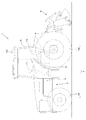
図9に示すように、トラクタ1は、走行装置7を有する走行車両(走行車体)3と、原動機4と、変速装置5とを備えている。走行装置7は、前輪7F及び後輪7Rを有する装置である。前輪7Fは、タイヤ型であってもクローラ型であってもよい。また、後輪7も、タイヤ型であってもクローラ型であってもよい。原動機4は、ディーゼルエンジン、電動モータ等である。変速装置5は、変速によって走行装置7の推進力を切換可能であると共に、走行装置7の前進、後進の切換が可能である。走行車両3にはキャビン9が設けられ、当該キャビン9内には運転席10が設けられている。   As shown in FIG. 9, the tractor 1 includes a traveling vehicle (traveling vehicle body) 3 having a traveling device 7, a prime mover 4, and a transmission 5. The traveling device 7 is a device having a front wheel 7F and a rear wheel 7R. The front wheel 7F may be a tire type or a crawler type. Further, the rear wheel 7 may be a tire type or a crawler type. The prime mover 4 is a diesel engine, an electric motor, or the like. The transmission 5 can switch the propulsive force of the traveling device 7 by shifting, and can also switch the traveling device 7 forward and backward. The traveling vehicle 3 is provided with a cabin 9, and a driver seat 10 is provided in the cabin 9.

また、走行車両3の後部には、3点リンク機構等で構成された連結部8が設けられている。連結部8には、作業装置2が着脱可能である。作業装置2を連結部8に連結することによって、走行車両3によって作業装置2を牽引することができる。作業装置2は、耕耘する耕耘装置、肥料を散布する肥料散布装置、農薬を散布する農薬散布装置、収穫を行う収穫装置、牧草等の刈取を行う刈取装置、牧草等の拡散を行う拡散装置、牧草等の集草を行う集草装置、牧草等の成形を行う成形装置等である。なお、図9では、作業装置2として耕耘装置を取り付けた例を示している。   In addition, a connecting portion 8 constituted by a three-point link mechanism or the like is provided at the rear portion of the traveling vehicle 3. The working device 2 can be attached to and detached from the connecting portion 8. By connecting the working device 2 to the connecting portion 8, the working device 2 can be pulled by the traveling vehicle 3. The working device 2 includes a tilling device for plowing, a fertilizer spraying device for spraying fertilizer, a pesticide spraying device for spraying agricultural chemicals, a harvesting device for harvesting, a harvesting device for cutting grass, a diffusion device for spreading grass, A grass collecting device for collecting grass and the like, and a molding device for forming grass and the like. In addition, in FIG. 9, the example which attached the tillage apparatus as the working apparatus 2 is shown.

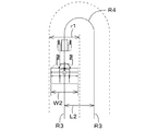
図1に示すように、変速装置5は、主軸(推進軸)5aと、主変速部5bと、副変速部5cと、シャトル部5dと、PTO動力伝達部5eと、を備えている。推進軸5aは、変速装置5のハウジングケースに回転自在に支持され、当該推進軸5aには、エンジン4のクランク軸からの動力が伝達される。主変速部5bは、複数のギア及び当該ギアの接続を変更するシフタを有している。主変速部5bは、複数のギアの接続(噛合)をシフタで適宜変更することによって、推進軸5aから入力された回転を変更して出力する(変速する)。   As shown in FIG. 1, the transmission 5 includes a main shaft (propulsion shaft) 5a, a main transmission unit 5b, an auxiliary transmission unit 5c, a shuttle unit 5d, and a PTO power transmission unit 5e. The propulsion shaft 5a is rotatably supported by the housing case of the transmission 5, and power from the crankshaft of the engine 4 is transmitted to the propulsion shaft 5a. The main transmission 5b has a plurality of gears and a shifter that changes the connection of the gears. The main transmission unit 5b changes and outputs (shifts) the rotation input from the propulsion shaft 5a by appropriately changing the connection (meshing) of a plurality of gears with a shifter.

副変速部5cは、主変速部5bと同様に、複数のギア及び当該ギアの接続を変更するシフタを有している。副変速部5cは、複数のギアの接続(噛合)をシフタで適宜変更することによって、主変速部5bから入力された回転を変更して出力する(変速する)。
シャトル部5dは、シャトル軸12と、前後進切替部13とを有している。シャトル軸12には、副変速部5cから出力された動力がギア等を介して伝達される。前後切換部13は、例えば、油圧クラッチ等で構成され、油圧クラッチの入切によってシャトル軸12の回転方向、即ち、トラクタ1の前進及び後進を切り換える。シャトル軸12は、後輪デフ装置に接続されている。後輪デフ装置は、後輪7Rが取り付けられた後車軸29Rを回転自在に支持している。
Similar to the main transmission unit 5b, the sub transmission unit 5c includes a plurality of gears and a shifter that changes connection of the gears. The auxiliary transmission unit 5c changes and outputs (shifts) the rotation input from the main transmission unit 5b by appropriately changing the connection (meshing) of a plurality of gears with a shifter.
The shuttle unit 5 d includes a shuttle shaft 12 and a forward / reverse switching unit 13. The power output from the auxiliary transmission unit 5c is transmitted to the shuttle shaft 12 via a gear or the like. The front / rear switching unit 13 is constituted by, for example, a hydraulic clutch or the like, and switches the rotation direction of the shuttle shaft 12, that is, forward and reverse of the tractor 1 by turning on and off the hydraulic clutch. The shuttle shaft 12 is connected to a rear wheel differential device. The rear wheel differential device rotatably supports a rear axle 29R to which the rear wheel 7R is attached.

PTO動力伝達部5eは、PTO推進軸14と、PTOクラッチ15とを有している。PTO推進軸14は、回転自在に支持され、推進軸5aからの動力が伝達可能である。PTO推進軸14は、ギア等を介してPTO軸16に接続されている。PTOクラッチ15は、例えば、油圧クラッチ等で構成され、油圧クラッチの入切によって、推進軸5aの動力をPTO推進軸14に伝達する状態と、推進軸5aの動力をPTO推進軸14に伝達しない状態とに切り換わる。   The PTO power transmission unit 5 e has a PTO propulsion shaft 14 and a PTO clutch 15. The PTO propulsion shaft 14 is rotatably supported and can transmit power from the propulsion shaft 5a. The PTO propulsion shaft 14 is connected to the PTO shaft 16 via a gear or the like. The PTO clutch 15 is composed of, for example, a hydraulic clutch, and the state in which the power of the propulsion shaft 5a is transmitted to the PTO propulsion shaft 14 and the power of the propulsion shaft 5a is not transmitted to the PTO propulsion shaft 14 by turning on and off the hydraulic clutch Switch to state.

図1に示すように、トラクタ1は、操舵装置11を備えている。操舵装置11は、ハンドル(ステアリングホイール)11aと、ハンドル11aの回転に伴って回転する回転軸(操舵軸)11bと、ハンドル11aの操舵を補助する補助機構(パワーステアリング機構)11cと、を有している。補助機構11cは、油圧ポンプ21と、油圧ポンプ21から吐出した作動油が供給される制御弁22と、制御弁22により作動するステアリングシリンダ23とを含んでいる。制御弁22は、制御信号に基づいて作動する電磁弁である。制御弁22は、例えば、スプール等の移動によって切り換え可能な3位置切換弁である。また、制御弁22は、操舵軸11bの操舵によっても切換可能である。ステアリングシリンダ23は、前輪7Fの向きを変えるアーム(ナックルアーム)24に接続されている。   As shown in FIG. 1, the tractor 1 includes a steering device 11. The steering device 11 includes a handle (steering wheel) 11a, a rotating shaft (steering shaft) 11b that rotates as the handle 11a rotates, and an auxiliary mechanism (power steering mechanism) 11c that assists the steering of the handle 11a. doing. The auxiliary mechanism 11 c includes a hydraulic pump 21, a control valve 22 to which hydraulic oil discharged from the hydraulic pump 21 is supplied, and a steering cylinder 23 that is operated by the control valve 22. The control valve 22 is an electromagnetic valve that operates based on a control signal. The control valve 22 is, for example, a three-position switching valve that can be switched by moving a spool or the like. The control valve 22 can also be switched by steering the steering shaft 11b. The steering cylinder 23 is connected to an arm (knuckle arm) 24 that changes the direction of the front wheel 7F.

したがって、ハンドル11aを操作すれば、当該ハンドル11aに応じて制御弁22の切換位置及び開度が切り換わり、当該制御弁22の切換位置及び開度に応じてステアリングシリンダ23が左又は右に伸縮することによって、前輪7Fの操舵方向を変更することができる。なお、上述した操舵機構11は一例であり、上述した構成に限定されない。
図1に示すように、トラクタ1は、制動装置を備えている。制動装置は、左制動装置25aと、右制動装置25bとを有している。左制動装置25a及び右制動装置25bは、
ディスク型の制動装置であり、制動する制動状態と、制動を解除する解除状態に切換可能である。左制動装置25aは、後車軸29Rの左側に設けられ、右制動装置25bは、後車軸29Rの右側に設けられている。例えば、運転席10の近傍には、左ブレーキペダルと、右ブレーキペダルとが設けられている。トラクタ1を操作するオペレータが左ブレーキペダルを操作する(踏み込む)ことによって、左ブレーキペダルに連結された左連結部材26aが制動方向へ動き、左制動装置25aを制動状態にすることができる。オペレータが右ブレーキペダルを操作する(踏み込む)ことによって、右ブレーキペダルに連結された右連結部材26bが制動方向へ動き、右制動装置25bを制動状態にすることができる。
Therefore, if the handle 11a is operated, the switching position and opening of the control valve 22 are switched according to the handle 11a, and the steering cylinder 23 is expanded or contracted to the left or right according to the switching position and opening of the control valve 22. By doing so, the steering direction of the front wheel 7F can be changed. In addition, the steering mechanism 11 mentioned above is an example, and is not limited to the structure mentioned above.
As shown in FIG. 1, the tractor 1 includes a braking device. The braking device includes a left braking device 25a and a right braking device 25b. The left braking device 25a and the right braking device 25b are
It is a disc-type braking device, and can be switched between a braking state for braking and a released state for releasing braking. The left braking device 25a is provided on the left side of the rear axle 29R, and the right braking device 25b is provided on the right side of the rear axle 29R. For example, a left brake pedal and a right brake pedal are provided in the vicinity of the driver's seat 10. When the operator operating the tractor 1 operates (depresses) the left brake pedal, the left connecting member 26a connected to the left brake pedal moves in the braking direction, and the left braking device 25a can be put into a braking state. When the operator operates (depresses) the right brake pedal, the right connecting member 26b connected to the right brake pedal moves in the braking direction, and the right braking device 25b can be put into a braking state.

また、左連結部材26aには、作動油により作動する左油圧作動部27aが連結されている。左油圧作動部27aには、油路を介して左制動弁28aが接続されている。左制動弁28aによって、左油圧作動部27aを作動させることにより、左連結部材26aを制動方向に移動させることができる。また、右連結部材26bには、作動油により作動する右油圧作動部27bが連結されている。右油圧作動部27bには、油路を介して右制動弁28bが接続されている。右制動弁28bによって、右油圧作動部27bを作動させることにより、右連結部材26bを制動方向に移動させることができる。なお、上述した制動装置に限定されない。   The left connecting member 26a is connected to a left hydraulic operating portion 27a that is operated by hydraulic oil. A left brake valve 28a is connected to the left hydraulic operating portion 27a through an oil passage. The left connecting member 26a can be moved in the braking direction by operating the left hydraulic operating portion 27a by the left brake valve 28a. The right connecting member 26b is connected to a right hydraulic operating portion 27b that is operated by hydraulic oil. A right braking valve 28b is connected to the right hydraulic operation unit 27b through an oil passage. The right connecting member 26b can be moved in the braking direction by operating the right hydraulic operating portion 27b with the right brake valve 28b. In addition, it is not limited to the braking device mentioned above.

トラクタ1は、制御装置18を備えている。制御装置18は、トラクタ1における走行系の制御、作業系の制御を行う装置である。制御装置18は、トラクタ1に搭載された様々な駆動部を制御する装置であって、例えば、原動機4のエンジン制御、連結部8を昇降する昇降装置の昇降制御等を行う。
トラクタ1は、位置検出装置30とを備えている。位置検出装置30は、走行車両3のキャビン9の天板に装着されている。なお、位置検出装置30は、キャビン9の天板に装着されているが、走行車両3における装着場所は限定されず、別の場所であってもよい。また、位置検出装置30は、作業装置2に装着されていてもよい。
The tractor 1 includes a control device 18. The control device 18 is a device that controls the traveling system and the working system in the tractor 1. The control device 18 is a device that controls various drive units mounted on the tractor 1. For example, the control device 18 performs engine control of the prime mover 4, elevating control of the elevating device that elevates and lowers the connecting unit 8, and the like.
The tractor 1 includes a position detection device 30. The position detection device 30 is mounted on the top plate of the cabin 9 of the traveling vehicle 3. In addition, although the position detection apparatus 30 is mounted on the top plate of the cabin 9, the mounting position on the traveling vehicle 3 is not limited and may be another place. Further, the position detection device 30 may be attached to the work device 2.

位置検出装置30は、衛星測位システムによって自己の位置(緯度、経度を含む測位情報)を検出する装置である。即ち、位置検出装置30は、測位衛星から送信された信号(測位衛星の位置、送信時刻、補正情報等)を受信し、受信した信号に基づいて位置(緯度、経度)を検出する。
なお、位置検出装置30は、測位衛星からの信号を受信可能な基地局(基準局)からの補正等の信号に基づいて補正した位置を、自己の位置(緯度、経度)として検出してもよい。また、位置検出装置30がジャイロセンサや加速度センサ等の慣性計測装置を有し、慣性計測装置によって補正した位置を、自己の位置として検出してもよい。
The position detection device 30 is a device that detects its own position (positioning information including latitude and longitude) by a satellite positioning system. That is, the position detection device 30 receives a signal (positioning satellite position, transmission time, correction information, etc.) transmitted from a positioning satellite, and detects a position (latitude, longitude) based on the received signal.
The position detection device 30 may detect a position corrected based on a signal such as correction from a base station (reference station) that can receive a signal from a positioning satellite as its own position (latitude, longitude). . Further, the position detection device 30 may include an inertial measurement device such as a gyro sensor or an acceleration sensor, and the position corrected by the inertial measurement device may be detected as its own position.

以上、位置検出装置30によれば、走行車両3の位置を位置検出装置30によって検出することができる。
図1に示すように、作業場の走行管理システムは、走行エリア設定部40と、作業エリア設定部41とを備えている。走行エリア設定部40及び作業エリア設定部41は、管理装置(コンピュータ)に設けられている。管理装置は、例えば、タブレット、スマートフォン、PDA等の携帯型の端末(携帯端末)、パーソナルコンピュータ、モニタ装置(表示装置)、サーバ等の固定型のコンピュータ等の固定型の端末(固定端末)である。管理装置が携帯端末である場合、オペレータ(トラクタ1を操作するオペレータ)、管理者(作業を管理する管理者等)が作業時に所持してもよい。管理装置が携帯端末である場合、オペレータ等がトラクタ1の操縦時に当該携帯端末をトラクタ1に装着してもよい。管理装置が固定端末のうち表示装置である場合、当該表示装置をトラクタ1に取付けてもよい。この実施形態では、管理装置は、トラクタ1に取付けた表示装置50であるとして説明を続ける。
As described above, according to the position detection device 30, the position of the traveling vehicle 3 can be detected by the position detection device 30.
As shown in FIG. 1, the workplace management system includes a travel area setting unit 40 and a work area setting unit 41. The travel area setting unit 40 and the work area setting unit 41 are provided in a management device (computer). The management device is, for example, a portable terminal (portable terminal) such as a tablet, a smartphone, or a PDA, a fixed terminal (fixed terminal) such as a fixed computer such as a personal computer, a monitor device (display device), or a server. is there. When the management device is a mobile terminal, an operator (an operator who operates the tractor 1) or an administrator (such as an administrator who manages work) may be possessed at the time of work. When the management device is a mobile terminal, an operator or the like may attach the mobile terminal to the tractor 1 when operating the tractor 1. When the management device is a display device among the fixed terminals, the display device may be attached to the tractor 1. In this embodiment, the description will be continued assuming that the management device is the display device 50 attached to the tractor 1.

表示装置50は、様々な情報を表示可能な装置であって、液晶パネル、タッチパネル、その他のパネルのいずれかを有する装置である。表示装置50は、CPU等で構成された制御部と、不揮発性のメモリ等から構成された記憶部19とを有している。走行エリア設定部40及び作業エリア設定部41は、表示装置50に設けられた電気・電子部品、当該制御部等に組み込まれたプログラム等から構成されている。   The display device 50 is a device that can display various kinds of information, and includes any one of a liquid crystal panel, a touch panel, and other panels. The display device 50 includes a control unit configured with a CPU and the like, and a storage unit 19 configured with a nonvolatile memory and the like. The travel area setting unit 40 and the work area setting unit 41 are configured by electric / electronic components provided in the display device 50, programs incorporated in the control unit, and the like.

図2Aに示すように、走行エリア設定部40は、走行車両3の作業場H1における走行可能エリア60を設定する。即ち、走行エリア設定部40は、作業場H1において走行車両3を走行させた際の走行位置(走行軌跡)に基づいて、走行可能エリア60を設定する。走行位置は、トラクタ1(走行車両3)の位置であって、位置検出装置30が検出した位置であってもよいし、位置検出装置30が検出した位置に基づいてトラクタ1の前端(走行車両3)の前端の位置を求め、当該前端の位置を走行位置にしてもよいし、位置検出装置30が検出した位置に基づいて前輪7Fの位置を求め、当該前輪7Fの位置を走行位置にしてもよい。   As shown in FIG. 2A, the travel area setting unit 40 sets a travelable area 60 in the work place H <b> 1 of the travel vehicle 3. That is, the travel area setting unit 40 sets the travelable area 60 based on the travel position (travel trajectory) when the travel vehicle 3 travels in the work place H1. The travel position may be the position of the tractor 1 (traveling vehicle 3) and may be a position detected by the position detection device 30, or based on the position detected by the position detection device 30, the front end of the tractor 1 (traveling vehicle). 3) The position of the front end may be obtained and the position of the front end may be set as the travel position, or the position of the front wheel 7F is obtained based on the position detected by the position detection device 30, and the position of the front wheel 7F is set as the travel position. Also good.

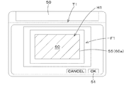
例えば、オペレータが表示装置50に対して所定の操作を行うと、図2Aに示すように、走行エリア設定部40は、当該表示装置50に設定画面T1を表示する。表示装置50に設定画面T1には、作業場H1を示すフィールドF1が表示される。フィールドF1には、位置(緯度、経度)が割り当てられている。ここで、オペレータが走行車両3を作業場H1を走行させると、フィールドF1上には、走行車両3が作業場H1の走行時における位置検出装置30にて検出した位置(走行位置)の走行軌跡55が表示される。即ち、走行エリア設定部40は、位置検出装置30が検出した走行位置を取得し、取得した走行位置に基づいて走行軌跡55を計算してフィールドF1上に走行軌跡55を表示する。例えば、設定画面T1に表示された完了ボタン51が選択されると、走行エリア設定部40は、走行軌跡55を、作業場H1における走行可能エリア60に設定する。例えば、走行可能エリア60を設定する場合、オペレータは、走行車両3を作業場(圃場)H1の輪郭に沿って走行させることから、作業場H1が平面視で矩形状(四角形)の場合は、走行可能エリア60は四角形となる。当然の如く、オペレータは、作業場H1の状態を確認しながら走行車両3を走行させるため、走行可能エリア60の形状は限定されず、多角形、円形等々の様々な形状となる。また、走行エリア設定部40は、走行軌跡55に対して直線補間の処理を行って、直線補間処理後の走行軌跡55を作業場H1における走行可能エリア60に設定してもよい。走行エリア設定部40によって、走行可能エリア60が設定されると、当該走行可能エリア60を示す位置データが記憶部19に記憶される。   For example, when the operator performs a predetermined operation on the display device 50, the traveling area setting unit 40 displays a setting screen T1 on the display device 50 as shown in FIG. 2A. A field F1 indicating the work place H1 is displayed on the setting screen T1 on the display device 50. A position (latitude, longitude) is assigned to the field F1. Here, when the operator causes the traveling vehicle 3 to travel through the work place H1, a travel locus 55 of a position (traveling position) detected by the position detection device 30 when the traveling vehicle 3 travels in the work place H1 is displayed on the field F1. Is displayed. That is, the travel area setting unit 40 acquires the travel position detected by the position detection device 30, calculates the travel locus 55 based on the acquired travel position, and displays the travel locus 55 on the field F1. For example, when the completion button 51 displayed on the setting screen T1 is selected, the travel area setting unit 40 sets the travel locus 55 to the travelable area 60 in the work place H1. For example, when the travelable area 60 is set, the operator travels the traveling vehicle 3 along the outline of the work place (agricultural field) H1, so that the work can be performed when the work place H1 is rectangular (rectangular) in plan view. The area 60 is a rectangle. As a matter of course, the operator travels the traveling vehicle 3 while confirming the state of the work place H1, so the shape of the travelable area 60 is not limited, and may be various shapes such as a polygon and a circle. The traveling area setting unit 40 may perform linear interpolation processing on the traveling locus 55 and set the traveling locus 55 after the linear interpolation processing in the travelable area 60 in the work place H1. When the travelable area 60 is set by the travel area setting unit 40, position data indicating the travelable area 60 is stored in the storage unit 19.

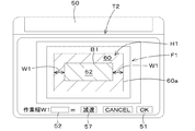
図2Bに示すように、作業エリア設定部41は、走行可能エリア60内に作業エリア62を設定する。例えば、オペレータが表示装置50に対して所定の操作を行うと、図2Bに示すように、作業エリア設定部41は、当該表示装置50に設定画面T2を表示する。なお、設定画面T1と設定画面T2とは同一の画面であってもよい。
表示装置50に設定画面T2には、作業場H1を示すフィールドF1、フィールドF1に示された走行可能エリア60を表示する。作業エリア設定部41は、設定画面T2に、作業幅W1を入力する作業幅入力部52を表示する。作業装置2の作業幅W1は、作業装置2の作業場H1に対して作業を施す幅であって、例えば、刈取装置、耕耘装置、成形装置等では、作業装置2の幅方向の一端から他端までの距離である。なお、作業装置2の作業幅W1を、作業装置2の幅方向の一端から他端までの距離よりも大きく設定してもよい。即ち、施肥、薬剤等の散布装置の場合は、作業装置2の作業幅W1は、散布幅である。
As shown in FIG. 2B, the work area setting unit 41 sets a work area 62 in the travelable area 60. For example, when the operator performs a predetermined operation on the display device 50, the work area setting unit 41 displays a setting screen T2 on the display device 50 as shown in FIG. 2B. The setting screen T1 and the setting screen T2 may be the same screen.
On the setting screen T2 on the display device 50, a field F1 indicating the work place H1 and a travelable area 60 indicated in the field F1 are displayed. The work area setting unit 41 displays a work width input unit 52 for inputting the work width W1 on the setting screen T2. The work width W1 of the work device 2 is a width for performing work on the work place H1 of the work device 2. For example, in a cutting device, a tilling device, a forming device, or the like, one end to the other end of the work device 2 in the width direction. It is the distance to. The work width W1 of the work device 2 may be set larger than the distance from one end to the other end of the work device 2 in the width direction. That is, in the case of a spraying device for fertilizer application, medicine, etc., the work width W1 of the work device 2 is the spray width.

作業幅入力部52に作業装置2の作業幅W1が入力された後、設定画面T2に表示された完了ボタン51が選択されると、作業エリア設定部41は、作業幅入力部53に入力された作業装置2の作業幅W1を取得する。作業エリア設定部41は、走行可能エリア60
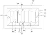
の境界(走行境界)60aを内側に向けて、作業幅W1だけシフトさせ、シフトしたシフト線B1に囲まれた範囲を、作業エリア62に設定する。即ち、作業エリア設定部41は、走行可能エリア60の走行境界と作業装置2における作業幅W1とに基づいて作業エリア62を設定する。なお、図2Cに示すように、作業エリア設定部41は、シフト線Bn=作業幅W1×走行可能エリア60の走行境界60aに対するシフト回数n、n=1,2・・・n)とし、任意のシフト回数nで求められるシフト線Bnで挟まれる領域を作業エリア62としてもよい。
After the work width W1 of the work device 2 is input to the work width input unit 52, when the completion button 51 displayed on the setting screen T2 is selected, the work area setting unit 41 is input to the work width input unit 53. The working width W1 of the working device 2 obtained is acquired. The work area setting unit 41 includes a travelable area 60
The boundary (running boundary) 60a is shifted inwardly by the work width W1, and a range surrounded by the shifted shift line B1 is set in the work area 62. That is, the work area setting unit 41 sets the work area 62 based on the travel boundary of the travelable area 60 and the work width W1 in the work device 2. As shown in FIG. 2C, the work area setting unit 41 sets the shift line Bn = work width W1 × the number of shifts n with respect to the travel boundary 60a of the travelable area 60, n = 1, 2,. The area between the shift lines Bn obtained by the number of shifts n may be the work area 62.

作業エリア設定部41は、例えば、フィールドF1上に示された作業エリア62をポインタ部56で選択し、完了ボタン51が選択されると、選択された作業エリア62を決定する。作業エリア設定部41によって、作業エリア62が設定されると、当該作業エリア62を示す位置データが記憶部19に記憶される。
以上によれば、走行エリア設定部40によって、実際にトラクタ1が作業場H1において走行できる走行可能エリア60を簡単に設定することができ、作業エリア設定部41によって走行可能エリア60内に作業エリア62を簡単に設定することができる。即ち、トラクタ1の実際の作業では、作業場H1と、実際にトラクタ1が走行できるエリアと、実際に作物等を作付けできるエリアとは異なるため、これら走行エリア設定部40及び作業エリア設定部41によって、走行できるエリアと作業場H1内にて当該作業場H1等に対して行うエリアとを適正にて設定することができる。特に、走行エリア設定部40は、作業場H1において走行車両3を走行させた際の走行位置に基づいて、走行可能エリア60を設定しているため、仮想的に設定したものと比べて、作業場H1の状態を反映することができる。
For example, the work area setting unit 41 selects the work area 62 shown on the field F1 with the pointer unit 56, and determines the selected work area 62 when the completion button 51 is selected. When the work area 62 is set by the work area setting unit 41, position data indicating the work area 62 is stored in the storage unit 19.
As described above, the travel area setting unit 40 can easily set the travelable area 60 in which the tractor 1 can actually travel in the work place H1, and the work area 62 can be set in the travelable area 60 by the work area setting unit 41. Can be set easily. That is, in the actual work of the tractor 1, the work area H1, the area where the tractor 1 can actually travel, and the area where crops and the like can be actually planted are different. The area that can be traveled and the area for the work place H1 and the like in the work place H1 can be set appropriately. In particular, since the travel area setting unit 40 sets the travelable area 60 based on the travel position when the travel vehicle 3 travels in the work place H1, the work area H1 is compared with what is virtually set. The state of can be reflected.

また、作業エリア設定部41は、走行可能エリア60の走行境界60aと作業装置2における作業幅W1とに基づいて作業エリア62を設定していることから、作業装置2における実際の作業を加味した範囲を作業エリア62として設定することができる。
また、トラクタ1に設けた表示装置50を用いて走行可能エリア60及び作業エリア62の設定及び表示を行うことができるため、オペレータは実際の作業場H1を確認しながら、これらの走行可能エリア60及び作業エリア62の設定をすることができる。
In addition, since the work area setting unit 41 sets the work area 62 based on the travel boundary 60a of the travelable area 60 and the work width W1 in the work device 2, the actual work in the work device 2 is taken into account. A range can be set as the work area 62.
Further, since the travelable area 60 and the work area 62 can be set and displayed using the display device 50 provided in the tractor 1, the operator can check the actual work area H1 while checking the actual work area H1. The work area 62 can be set.

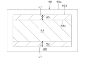
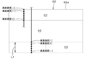
また、作業エリア設定部41は、作業エリア62に走行車両3の減速を実行する減速エリアを設定してもよい。作業エリア設定部41は、図2に示す設定画面T2に表示された減速設定ボタン57を選択すると、例えば、図2Dに示すように、作業エリア62上に減速エリア63を表示する。減速エリア63は、作業エリア62の境界62aから内側に設定されるエリアである。例えば、減速エリア63の境界63aは、作業エリア62の境界62aから所定距離L1だけシフトした位置に設定される。図2Dの場合、減速エリア63の境界63aと、作業エリア62の境界62aとの間が、減速エリア63に設定される。   Further, the work area setting unit 41 may set a deceleration area in the work area 62 for executing deceleration of the traveling vehicle 3. When the work area setting unit 41 selects the deceleration setting button 57 displayed on the setting screen T2 illustrated in FIG. 2, for example, as illustrated in FIG. 2D, the work area setting unit 41 displays the deceleration area 63 on the work area 62. The deceleration area 63 is an area set on the inner side from the boundary 62 a of the work area 62. For example, the boundary 63a of the deceleration area 63 is set at a position shifted from the boundary 62a of the work area 62 by a predetermined distance L1. In the case of FIG. 2D, the space between the boundary 63 a of the deceleration area 63 and the boundary 62 a of the work area 62 is set as the deceleration area 63.

作業エリア設定部41は、減速エリア63において、走行車両3の減速する速度を段階的に設定してもよい。作業エリア設定部41は、減速エリア63の境界63aにおける走行車両3の速度(減速開始速度)を100%とし、走行車両3が作業エリア62の境界62aに到達した時点で走行車両3の速度を零にする。図2Eに示すように、例えば、作業エリア設定部41は、減速速度[i](km/h)=減速開始速度(km/h)×[100%−i×定数%(i=1・・・i)]により、走行車両3の減速する速度を設定する。なお、定数は、表示装置50等で任意に設定される値、又は、予め設定された値であって、例えば、定数=10%の場合は、10段階で減速させることができる。   The work area setting unit 41 may set the speed at which the traveling vehicle 3 decelerates stepwise in the deceleration area 63. The work area setting unit 41 sets the speed of the traveling vehicle 3 (deceleration start speed) at the boundary 63a of the deceleration area 63 to 100%, and sets the speed of the traveling vehicle 3 when the traveling vehicle 3 reaches the boundary 62a of the work area 62. Set to zero. As shown in FIG. 2E, for example, the work area setting unit 41 sets deceleration speed [i] (km / h) = deceleration start speed (km / h) × [100% −i × constant% (i = 1... I)] sets the speed at which the traveling vehicle 3 decelerates. The constant is a value arbitrarily set by the display device 50 or the like, or a preset value. For example, when the constant = 10%, the constant can be decelerated in 10 steps.

作業エリア設定部41によって、減速エリア63が設定されると、当該減速エリア63を示す位置データが記憶部19に記憶される。また、作業エリア設定部41によって、減
速エリア63に減速速度が設定されると、減速エリア63の位置と共に減速速度が設定される。なお、減速速度は、減速エリア63で示された位置と対応付けられて記憶部19に記憶される。
When the deceleration area 63 is set by the work area setting unit 41, position data indicating the deceleration area 63 is stored in the storage unit 19. When the deceleration speed is set in the deceleration area 63 by the work area setting unit 41, the deceleration speed is set together with the position of the deceleration area 63. The deceleration speed is stored in the storage unit 19 in association with the position indicated by the deceleration area 63.

これによれば、作業エリア設定部41によって走行車両3の減速を実行する減速エリア63を設定することができる。そのため、トラクタ1(走行車両3)をスムーズに作業エリア62の境界62aに停止させることができる。
また、走行可能エリア60に走行車両3の走行予定ルートを設定してもよい。図1に示すように、作業場の走行管理システムは、ルート設定部44を備えている。ルート設定部44は、表示装置50に設けられた電気・電子部品、制御部等に組み込まれたプログラム等から構成されている。ルート設定部44は、走行可能エリア60に走行車両3の走行予定ルートを設定する。
According to this, the work area setting unit 41 can set the deceleration area 63 in which the traveling vehicle 3 is decelerated. Therefore, the tractor 1 (traveling vehicle 3) can be smoothly stopped at the boundary 62a of the work area 62.
Further, the planned travel route of the traveling vehicle 3 may be set in the travelable area 60. As shown in FIG. 1, the workplace management system includes a route setting unit 44. The route setting unit 44 includes an electric / electronic component provided in the display device 50, a program incorporated in the control unit, and the like. The route setting unit 44 sets the planned travel route of the traveling vehicle 3 in the travelable area 60.

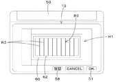
具体的には、オペレータが表示装置50に対して所定の操作を行うと、図3に示すように、ルート設定部44は、当該表示装置50に設定画面T3を表示する。ルート設定部44は、設定画面T3に走行可能エリア60及び作業エリア62を表示する。オペレータ等は、表示装置50のインターフェース等を用いて、設定画面T3に表示された走行可能エリア60上に、走行ルート(走行予定ルート)R2を設定する。例えば、走行ルートR2として、トラクタ1を直進させる直進部R3を設定する。走行ルートR2における直進部R3は、走行可能エリア60の位置(緯度、経度)に対応付けられており、少なくとも直進部R3に対応する位置を、表示装置50の設定画面T3上で設定することができる。設定画面T3において、完了ボタン51が選択されると、ルート設定部44による走行ルートR2の設定が完了し、設定された走行ルートR2は記憶部19に記憶される。   Specifically, when the operator performs a predetermined operation on the display device 50, the route setting unit 44 displays a setting screen T3 on the display device 50 as shown in FIG. The route setting unit 44 displays the travelable area 60 and the work area 62 on the setting screen T3. The operator or the like uses the interface of the display device 50 or the like to set a travel route (travel planned route) R2 on the travelable area 60 displayed on the setting screen T3. For example, a straight traveling portion R3 that causes the tractor 1 to travel straight is set as the traveling route R2. The straight portion R3 in the travel route R2 is associated with the position (latitude, longitude) of the travelable area 60, and at least a position corresponding to the straight portion R3 can be set on the setting screen T3 of the display device 50. it can. When the completion button 51 is selected on the setting screen T3, the setting of the travel route R2 by the route setting unit 44 is completed, and the set travel route R2 is stored in the storage unit 19.

これによれば、ルート設定部44によって、走行可能エリア60内に走行ルートR2を設定することができる。そのため、仮想的に決められたエリアに対して走行ルートR2を設定するのに比べて、より実態にあった走行ルートR2の設定を行うことができ、作業場H1内におけるトラクタ1等による作業を効率化することができる。
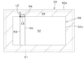
また、トラクタ1(走行車両)3を旋回する旋回エリアを設定してもよい。図1に示すように、作業場の走行管理システムは、旋回エリア設定部45を備えている。旋回エリア設定部45は、表示装置50に設けられた電気・電子部品、制御部等に組み込まれたプログラム等から構成されている。旋回エリア設定部45は、走行可能エリア60のうち作業エリア62を除くエリア内に走行車両3が旋回する旋回エリア64を設定する。例えば、図3に示すように、設定画面T3に表示された旋回設定ボタン58が選択されると、図4に示すように、旋回エリア設定部45は、走行可能エリア60の境界60aと、作業エリア62の境界62aとの間の領域を旋回エリア64に設定する。なお、走行ルートR2の直進部R3が設定されている場合は、作業エリア62の境界62aを、隣接する直進部R3の間隔L2だけ走行可能エリア60側にシフトし、シフト線C1で囲まれる領域を旋回エリア64に設定してもよい。
According to this, the travel route R <b> 2 can be set in the travelable area 60 by the route setting unit 44. Therefore, compared to setting the travel route R2 for the virtually determined area, it is possible to set the travel route R2 that is more realistic, and the work by the tractor 1 and the like in the work place H1 is efficient. Can be
Further, a turning area for turning the tractor 1 (traveling vehicle) 3 may be set. As shown in FIG. 1, the workplace management system includes a turning area setting unit 45. The turning area setting unit 45 includes an electric / electronic component provided in the display device 50, a program incorporated in the control unit, and the like. The turning area setting unit 45 sets a turning area 64 in which the traveling vehicle 3 turns in an area excluding the work area 62 in the travelable area 60. For example, as shown in FIG. 3, when the turn setting button 58 displayed on the setting screen T3 is selected, the turn area setting unit 45, as shown in FIG. An area between the boundary 62 a of the area 62 is set as the turning area 64. When the straight traveling part R3 of the travel route R2 is set, the boundary 62a of the work area 62 is shifted to the travelable area 60 side by the interval L2 between the adjacent straight traveling parts R3, and is surrounded by the shift line C1. May be set in the turning area 64.

また、作業装置2を接続したトラクタ1(走行車両3)を旋回させた場合に、隣接する直進部3Rのうち一方の直進部3Rから他方の直進部3Rにトラクタ1が移動するのが難しいとき、旋回エリア設定部45は、表示装置50に「走行ルートR2の設定において隣接する直進部R3を跨いでのトラクタ1(走行車両3)の旋回が設定上難しいこと」を表示する。言い換えれば、隣接する直進部3Rの間隔L2に比べてトラクタ1の旋回半径が大きく、旋回が難しい場合に、旋回エリア設定部45は、表示装置50に上述したような内容を表示する。   Further, when the tractor 1 (traveling vehicle 3) connected to the work device 2 is turned, it is difficult for the tractor 1 to move from one rectilinear portion 3R to the other rectilinear portion 3R among the adjacent rectilinear portions 3R. The turning area setting unit 45 displays on the display device 50 that “turning of the tractor 1 (traveling vehicle 3) across the adjacent straight traveling part R3 is difficult in setting in setting the traveling route R2”. In other words, when the turning radius of the tractor 1 is larger than the interval L2 between the adjacent rectilinear portions 3R and turning is difficult, the turning area setting unit 45 displays the above-described content on the display device 50.

これによれば、旋回エリア設定部45によって、走行可能エリア60のうち作業エリア62を除くエリア内に走行車両3が旋回する旋回エリア64を設定することができる。例
えば、トラクタ1を直進させたり旋回させたりしながら作業を行う場合に、適正に旋回するスペースを設定することができ、作業場H1における作業を効率化することができる。
なお、図4に示すように、ルート設定部44によって走行ルートR2上であって旋回エリア64に旋回部R4を設定してもよい。また、上述した実施形態では、ルート設定部44によって、走行ルートR2として、直進部R3、旋回部R4を設定しているが、直進及び旋回以外のルートを設定してもよい。例えば、作業エリア62において、略S字、略L字等の曲線部を設定してもよい。
According to this, the turning area setting unit 45 can set a turning area 64 in which the traveling vehicle 3 turns in an area excluding the work area 62 in the travelable area 60. For example, when the work is performed while the tractor 1 is moved straight or turned, it is possible to set a space for turning appropriately, and the work in the work place H1 can be made efficient.
As shown in FIG. 4, the turning unit R <b> 4 may be set in the turning area 64 on the traveling route R <b> 2 by the route setting unit 44. In the above-described embodiment, the route setting unit 44 sets the straight traveling unit R3 and the turning unit R4 as the traveling route R2. However, a route other than the straight traveling and the turning may be set. For example, in the work area 62, a curved portion such as a substantially S shape or a substantially L shape may be set.

トラクタ1は、少なくとも走行可能エリア60内を走行する。走行ルートR2を設定した場合は、トラクタ1は、ルート設定部44で設定した走行ルートR2を走行する。トラクタ1の走行に関する制御は、制御装置18により行う。
図1に示すように、制御装置18は、走行制御部46を有している。走行制御部46は、制御装置18に設けられた電気・電子部品、当該制御装置18に組み込まれたプログラム等から構成されている。制御装置18には、指令スイッチ59が接続されている。指令スイッチ59は、ON/OFFに切り換え可能なスイッチであって、ONである場合に自動走行による制御(自動走行制御)を有効にし、OFFである場合に自動走行制御を無効にする。なお、表示装置50に指令スイッチ59を示す図形を表示して、指令スイッチ59の操作によって、走行制御部46による制御を有効又は無効に切り換えてもよい。
The tractor 1 travels at least in the travelable area 60. When the travel route R2 is set, the tractor 1 travels the travel route R2 set by the route setting unit 44. Control related to traveling of the tractor 1 is performed by the control device 18.
As shown in FIG. 1, the control device 18 includes a travel control unit 46. The travel control unit 46 includes electrical / electronic components provided in the control device 18, a program incorporated in the control device 18, and the like. A command switch 59 is connected to the control device 18. The command switch 59 is a switch that can be switched ON / OFF. When the command switch 59 is ON, the control by the automatic travel (automatic travel control) is validated, and when it is OFF, the automatic travel control is invalidated. Note that a graphic indicating the command switch 59 may be displayed on the display device 50, and the control by the traveling control unit 46 may be switched between valid and invalid by operating the command switch 59.

イグニッションスイッチ等をONすることで原動機4の始動後、指令スイッチ59がONされると、走行制御部46による自動走行制御が開始される。走行制御部46は、原動機4の回転数、アクセル等の設定値、変速装置5による変速段等を予め定められた値に設定して、走行車両3の走行を開始する。走行制御部46は、原動機4の回転数、アクセル等の設定値、変速装置5による変速段等によって、トラクタ1(走行車両3)の車速(速度)を、例えば、1km/h以下に設定する。言い換えれば、走行制御部46は、オペレータがトラクタ1の乗り降りができる程度の速度(例えば、歩行速度以下)に設定する。   When the command switch 59 is turned on after the prime mover 4 is started by turning on the ignition switch or the like, automatic running control by the running control unit 46 is started. The traveling control unit 46 starts the traveling of the traveling vehicle 3 by setting the rotational speed of the prime mover 4, the set value of the accelerator, the gear position by the transmission device 5, and the like to predetermined values. The traveling control unit 46 sets the vehicle speed (speed) of the tractor 1 (traveling vehicle 3) to, for example, 1 km / h or less based on the number of rotations of the prime mover 4, the set value of the accelerator and the like, the gear position by the transmission 5 and the like. . In other words, the traveling control unit 46 sets the speed at which the operator can get on and off the tractor 1 (for example, the walking speed or less).

また、走行制御部46は、トラクタ1の走行位置と、走行ルートR2で示された位置(走行予定位置)とを比較し、走行位置と走行予定位置とが一致している場合は、操舵装置11におけるハンドル11aの操舵角及び操舵方向(前輪7Fの操舵角及び操舵方向)を変更せずに保持する(制御弁22の開度及び切換位置を変更せずに維持する)。一方、走行制御部46は、走行位置と走行予定位置とが一致していない場合、当該走行位置と走行予定位置との偏差(ズレ量)が零となるように、操舵装置11におけるハンドル11aの操舵角及び/又は操舵方向を変更する(制御弁22の開度及び/又は切換位置を変更する)。また、走行ルートR2の方位とトラクタ1(走行車両3)の進行方向(走行方向)の方位(車体方位)とが異なる場合(走行ルートR2に対する車体方位の角度θが閾値以上である場合)、走行制御部46は、角度θが零(車体方位が走行ルートR2の方位に一致)するように操舵角を設定する。   Further, the traveling control unit 46 compares the traveling position of the tractor 1 with the position (planned traveling position) indicated by the traveling route R2, and if the traveling position matches the planned traveling position, the steering device 11 is maintained without changing the steering angle and steering direction of the handle 11a (the steering angle and steering direction of the front wheel 7F) (the opening degree and switching position of the control valve 22 are maintained without being changed). On the other hand, when the travel position does not match the planned travel position, the travel control unit 46 sets the handle 11a of the steering device 11 so that the deviation (deviation amount) between the travel position and the planned travel position becomes zero. The steering angle and / or steering direction is changed (the opening and / or switching position of the control valve 22 is changed). Further, when the direction of the travel route R2 and the direction (vehicle body direction) of the traveling direction (traveling direction) of the tractor 1 (traveling vehicle 3) are different (when the angle θ of the vehicle body direction with respect to the travel route R2 is greater than or equal to the threshold value), The traveling control unit 46 sets the steering angle so that the angle θ is zero (the vehicle body direction coincides with the direction of the traveling route R2).

以上によれば、走行制御部46は、自動走行制御において、走行速度を自動的に決定する(速度制御)と、自動的に操舵を行うオートステアリング制御(自動操舵制御)を実行する。なお、走行制御部46は、偏差(位置偏差)に基づいて求めた操舵角と、方位(方位偏差)に基づいて求めた操舵角とに基づいて、最終の操舵角を設定してもよい。上述した実施形態における速度制御及び自動操舵制御の設定は一例であり、限定されない。   According to the above, the traveling control unit 46 performs automatic steering control (automatic steering control) for automatically steering when the traveling speed is automatically determined (speed control) in the automatic traveling control. The traveling control unit 46 may set the final steering angle based on the steering angle obtained based on the deviation (position deviation) and the steering angle obtained based on the azimuth (azimuth deviation). The setting of the speed control and the automatic steering control in the embodiment described above is an example and is not limited.

走行制御部46は、走行車両3を走行させる際に、少なくとも走行可能エリア60及び作業エリア62に関する記憶部19の位置データ等を参照する。そして、走行制御部46は、走行可能エリア60内に設定された作業エリア62を、直進部R3に沿って直進したり、曲線部に沿って蛇行等をしながら走行している状態で、当該走行車両3が作業エリア62の境界(停止ライン)62aに達した場合、即ち、走行位置が停止ライン62aに一
致した場合に、走行車両3を停止する。例えば、走行制御部46は、左制動弁28a及び右制動弁28bに制御信号を出力することで左制動装置25a及び右制動装置25bによる制動により、走行車両3を停止する。また、走行制御部46は、主変速部5b、副変速部5c、シャトル部5dの少なくとも1つを中立(ニュートラル)に設定して、走行車両3の速度を低下させる。
The travel control unit 46 refers to at least the position data of the storage unit 19 related to the travelable area 60 and the work area 62 when the traveling vehicle 3 travels. Then, the traveling control unit 46 travels in the work area 62 set in the travelable area 60 while traveling straight along the straight traveling portion R3 or meandering along the curved portion. When the traveling vehicle 3 reaches the boundary (stop line) 62a of the work area 62, that is, when the traveling position coincides with the stop line 62a, the traveling vehicle 3 is stopped. For example, the traveling control unit 46 stops the traveling vehicle 3 by braking the left braking device 25a and the right braking device 25b by outputting control signals to the left braking valve 28a and the right braking valve 28b. In addition, the traveling control unit 46 sets at least one of the main transmission unit 5b, the auxiliary transmission unit 5c, and the shuttle unit 5d to be neutral (neutral), and reduces the speed of the traveling vehicle 3.

また、走行制御部46は、減速エリア63が設定されている場合、記憶部19に記憶された減速エリア63の位置データを参照し、走行車両3が減速エリア63に入った時点で減速を開始する。走行制御部46は、例えば、走行車両3が作業エリア62の停止ラインと略一致する位置で停止させる。また、減速エリア63において、走行車両3の減速速度が設定されている場合は、記憶部19に記憶された減速エリア63の位置データ及び減速速度等を参照する。そして、走行制御部46は、トラクタ1(走行車両3)の速度(車速)を検出する速度検出装置31で検出された速度と、減速速度とが一致するように速度制御を実行し、走行車両3を徐々に減速させる。トラクタ1が停止すると、走行制御部46は、自動走行制御を有効から無効に切り換える。即ち、走行制御部46は、指令スイッチ59をONからOFFに切り換えるか、又は、指令スイッチ59がONであっても、自動走行制御を有効から無効に切り換える。   Further, when the deceleration area 63 is set, the traveling control unit 46 refers to the position data of the deceleration area 63 stored in the storage unit 19 and starts deceleration when the traveling vehicle 3 enters the deceleration area 63. To do. For example, the traveling control unit 46 stops the traveling vehicle 3 at a position that substantially matches the stop line of the work area 62. Further, when the deceleration speed of the traveling vehicle 3 is set in the deceleration area 63, the position data, the deceleration speed, and the like of the deceleration area 63 stored in the storage unit 19 are referred to. Then, the traveling control unit 46 executes speed control so that the speed detected by the speed detecting device 31 that detects the speed (vehicle speed) of the tractor 1 (traveling vehicle 3) matches the deceleration speed, and the traveling vehicle. Decrease 3 gradually. When the tractor 1 stops, the traveling control unit 46 switches automatic traveling control from valid to invalid. That is, the travel control unit 46 switches the command switch 59 from ON to OFF, or switches the automatic travel control from valid to invalid even when the command switch 59 is ON.

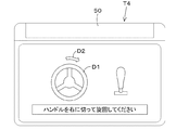
表示装置50は、走行制御部46からトラクタ1が停止したことを受けて、次の操作(操縦)の指示を報知する。図5に示すように、表示装置50は案内画面(指示画面)T4を表示する。案内画面T4では、トラクタ1に設けられた操縦装置(例えば、ハンドル11a、レバー等)の図形D1を表示する。表示装置50は、例えば、走行可能エリア60と作業エリア62との間に旋回エリア64が設定されている場合、ハンドル11aを示す図形D1に旋回方向を示す図形D2を表示する。なお、旋回方向は、旋回部R4で得られることができる。なお、表示装置50は、次の操作の指示を表示で行っているが、音(音声)等で行ってもよい。   In response to the stop of the tractor 1 from the traveling control unit 46, the display device 50 notifies the instruction of the next operation (maneuvering). As shown in FIG. 5, the display device 50 displays a guidance screen (instruction screen) T4. On the guidance screen T4, a figure D1 of a control device (for example, a handle 11a, a lever, etc.) provided in the tractor 1 is displayed. For example, when the turning area 64 is set between the travelable area 60 and the work area 62, the display device 50 displays the figure D2 indicating the turning direction on the figure D1 indicating the handle 11a. The turning direction can be obtained at the turning portion R4. In addition, although the display apparatus 50 is performing the instruction | indication of the next operation on a display, you may perform with a sound (voice | voice) etc.

走行制御部46は、走行車両3の停止後、トラクタ1に設けられた操縦検出部47によって走行車両3が操縦された場合、走行車両3の走行を再開する。例えば、操縦検出部47は、制御装置18に設けられた電気・電子部品、当該制御装置47等に組み込まれたプログラム等、或いは、操舵装置11に設けられたセンサ等で構成されている。オペレータによってハンドル11aが操作され、オペレータの操作によって回転軸11b又は補助機構11cに所定の負荷が検出されると、操舵装置11は、走行車両3が操縦されたと判断する。なお、操縦検出部47は、操舵装置11以外の箇所、アクセル等に設けられアクセル操作によって走行車両3が操縦されたと判断してもよい。   The traveling control unit 46 resumes traveling of the traveling vehicle 3 when the traveling vehicle 3 is steered by the steering detection unit 47 provided in the tractor 1 after the traveling vehicle 3 is stopped. For example, the steering detection unit 47 includes an electric / electronic component provided in the control device 18, a program incorporated in the control device 47 or the like, or a sensor provided in the steering device 11. When the handle 11a is operated by the operator and a predetermined load is detected on the rotating shaft 11b or the auxiliary mechanism 11c by the operator's operation, the steering device 11 determines that the traveling vehicle 3 has been steered. Note that the steering detection unit 47 may determine that the traveling vehicle 3 has been steered by an accelerator operation provided at a location other than the steering device 11, such as an accelerator.

走行制御部46は、上述したように旋回エリア64が設定されている場合において、操縦検出部47によってオペレータの操縦(手動操縦)ハンドル11a等が操作されると、旋回エリア64において走行車両3の旋回を有効に設定して、オペレータによる操縦を受け付ける。即ち、走行制御部46は、自動走行制御を停止した状態で手動走行制御に切り換え、オペレータの操縦に応じてトラクタ1(走行車両3)を制御する。つまり、走行制御部46は、アクセルにより設定された原動機4の回転数、変速装置5を操作するレバーの入力値等、運転席10の近傍に設けられた操縦系の操縦に応じてトラクタ1を手動により走行させる。   When the turning area 64 is set as described above, the traveling control unit 46 operates the steering (manual steering) handle 11a of the operator by the operation detecting unit 47, and the traveling vehicle 3 is moved in the turning area 64. The turning is set to be effective, and the operation by the operator is accepted. That is, the traveling control unit 46 switches to the manual traveling control in a state where the automatic traveling control is stopped, and controls the tractor 1 (the traveling vehicle 3) according to the operation of the operator. That is, the traveling control unit 46 controls the tractor 1 according to the operation of the operation system provided in the vicinity of the driver's seat 10 such as the rotation speed of the prime mover 4 set by the accelerator and the input value of the lever that operates the transmission 5. Run manually.

なお、ルート設定部44によって直進部R3が設定され、旋回エリア設定部45によって旋回エリア64が設定されている場合、図6A、6Bに示すように、走行制御部46は、トラクタ1の停止位置(現在の走行位置)SP1と、直進部R3と、作業装置2の幅W2等から旋回が可能であるか否かを判断してもよい。図6Aに示すように、隣接する直進部R3の間隔L2に対して停止位置SP1における旋回半径r1が小さい場合(r1≦L
2)、走行制御部46は、旋回が可能であると判断する。一方、図6Bに示すように、隣接する直進部R3の間隔L2に対して旋回半径r1が大きい場合(r1>L2)、走行制御部46は、旋回が困難であると判断する。表示装置50は、旋回が可能である場合には案内画面T4等に「旋回が可能である旨」を表示する。また、表示装置50は、旋回が困難である場合には案内画面T4等に「旋回が困難である旨」を表示する。表示装置50は、旋回が困難である場合には、旋回が可能となる旋回部R4を表示する。旋回エリア設定部45は、少なくとも隣接する直進部R3及び旋回部R4を補正して、表示装置50は、補正後の理想的な旋回部R4を表示する。
When the straight traveling portion R3 is set by the route setting unit 44 and the turning area 64 is set by the turning area setting unit 45, the traveling control unit 46 sets the stop position of the tractor 1 as shown in FIGS. 6A and 6B. It may be determined whether or not turning is possible based on (current travel position) SP1, the rectilinear portion R3, the width W2 of the work device 2, and the like. As shown in FIG. 6A, when the turning radius r1 at the stop position SP1 is smaller than the interval L2 between the adjacent rectilinear portions R3 (r1 ≦ L
2) The traveling control unit 46 determines that turning is possible. On the other hand, as shown in FIG. 6B, when the turning radius r1 is larger than the interval L2 between the adjacent straight parts R3 (r1> L2), the traveling control unit 46 determines that turning is difficult. When the turning is possible, the display device 50 displays “turning is possible” on the guidance screen T4 or the like. Further, the display device 50 displays “turning is difficult” on the guidance screen T4 or the like when turning is difficult. When the turning is difficult, the display device 50 displays the turning portion R4 that can turn. The turning area setting unit 45 corrects at least the adjoining rectilinear part R3 and the turning part R4, and the display device 50 displays the corrected ideal turning part R4.

上述した実施形態では、旋回エリア64に入る前にトラクタ1を停止させているが、これに代えて、走行制御部46は、旋回エリア64にて自動的に旋回を行った後に旋回エリア64と作業エリア62との境界にて停止を行ってもよい。この場合、旋回エリア64に旋回部R4が設定されていることを前提に説明を進める。
図7に示すように、走行制御部46は、走行車両3が作業エリア62内を走行している状態で走行位置が停止ライン62aに一致した場合、走行車両3を停止させず、旋回エリア64にて操舵装置11を制御することにより、走行車両3を旋回させる。走行車両3が旋回エリア64内を走行している状態において、走行位置が作業エリア62の境界(停止ライン)62aに達した場合、走行制御部46は、走行車両3を停止する。即ち、走行制御部46は、自動走行制御において直進だけでなく旋回も実行する。走行車両3の旋回後では、走行制御部46は、指令スイッチ59をONからOFFに切り換える。走行車両3の停止後、指令スイッチ59をOFFからONにすると、走行制御部46は、自動走行を開始して、直進部R3に沿ってトラクタ1を走行させる。
In the embodiment described above, the tractor 1 is stopped before entering the turning area 64. Instead, the traveling control unit 46 automatically turns in the turning area 64 and then turns into the turning area 64. You may stop at the boundary with the work area 62. In this case, the description will be made on the assumption that the turning portion R4 is set in the turning area 64.
As shown in FIG. 7, the traveling control unit 46 does not stop the traveling vehicle 3 and stops the turning area 64 when the traveling position matches the stop line 62 a while the traveling vehicle 3 is traveling in the work area 62. The traveling vehicle 3 is turned by controlling the steering device 11 at. In a state where the traveling vehicle 3 is traveling in the turning area 64, when the traveling position reaches the boundary (stop line) 62a of the work area 62, the traveling control unit 46 stops the traveling vehicle 3. That is, the traveling control unit 46 performs not only straight traveling but also turning in the automatic traveling control. After the traveling vehicle 3 turns, the traveling control unit 46 switches the command switch 59 from ON to OFF. When the command switch 59 is turned from OFF to ON after the traveling vehicle 3 stops, the traveling control unit 46 starts automatic traveling and causes the tractor 1 to travel along the straight traveling portion R3.

なお、上述した実施形態では、旋回エリアA3における旋回後に指令スイッチ59をOFFからONにすることによって走行制御部46は、自動走行を開始しているが、オペレータの音声によって自動走行を開始してもよいし、運転席10の操縦系の操縦(アクセル、ブレーキ)等の操作によって自動走行を開始してもよい。つまり、オペレータの何らかのアクションによって、自動走行を開始してもよい。   In the above-described embodiment, the travel control unit 46 starts the automatic travel by turning the command switch 59 from OFF to ON after the turn in the turn area A3. Alternatively, the automatic traveling may be started by an operation such as operation (accelerator, brake) of the operation system of the driver's seat 10. That is, the automatic traveling may be started by some action of the operator.

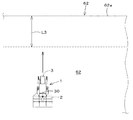
図1に示すように、トラクタ1は、報知装置65を備えている。報知装置65は、停止ライン62aと走行位置との関係に基づいて、走行車両3の走行状態を報知する。報知装置65は、トラクタ1に設けた前照灯、作業灯、スピーカ、表示装置50等である。図8に示すように、報知装置65は、例えば、自動走行によって走行車両3が作業エリア62内を走行している状況下において、走行車両3の走行位置と作業エリア62の停止ライン62aとの距離L3が所定以上であって両者が離れている場合は、走行車両3の走行状態の報知は停止している。一方、報知装置65は、距離L3が所定未満であって走行車両3が停止ライン62aに近い場合、走行車両3の走行状態として、走行車両3が停止ライン62aに近いことを報知する。例えば、報知装置65が前照灯や作業灯である場合、前照灯や作業灯を点灯又は点滅させることで走行車両3が停止ライン62aに近いことを知らせる。報知装置65がスピーカである場合、音声等によって走行車両3が停止ライン62aに近いことを知らせる。報知装置65が表示装置50である場合、当該表示装置50に走行車両3が停止ライン62aに近いことを表示する。   As shown in FIG. 1, the tractor 1 includes a notification device 65. The notification device 65 notifies the traveling state of the traveling vehicle 3 based on the relationship between the stop line 62a and the traveling position. The notification device 65 is a headlight, a work light, a speaker, a display device 50 or the like provided in the tractor 1. As shown in FIG. 8, the notification device 65, for example, between the travel position of the travel vehicle 3 and the stop line 62 a of the work area 62 in a situation where the travel vehicle 3 travels in the work area 62 by automatic travel. When the distance L3 is equal to or greater than the predetermined distance and the two are separated, the notification of the traveling state of the traveling vehicle 3 is stopped. On the other hand, when the distance L3 is less than the predetermined value and the traveling vehicle 3 is close to the stop line 62a, the notification device 65 notifies the traveling state of the traveling vehicle 3 that the traveling vehicle 3 is close to the stop line 62a. For example, when the notification device 65 is a headlamp or a work lamp, the headlamp or the work lamp is turned on or blinked to notify that the traveling vehicle 3 is close to the stop line 62a. When the notification device 65 is a speaker, the fact that the traveling vehicle 3 is close to the stop line 62a is notified by voice or the like. When the notification device 65 is the display device 50, the display device 50 displays that the traveling vehicle 3 is close to the stop line 62a.

以上によれば、報知装置65によって、停止ライン62aと走行位置との関係に基づいて、走行車両の走行状態、例えば、走行車両3が停止ライン62aに近いことを報知している。そのため、トラクタ1を自動走行させている状況下で、オペレータがトラクタ1から降車して作業を行っている場合は、報知装置65の報知によってトラクタ1(走行車両3)が停止ライン62aに近づきつつあることを把握することができる。これにより、オペレータがトラクタ1が停止ライン62aに近づいた時点で、当該トラクタ1に乗車することで当該トラクタ1の停止後に旋回等の次の操作を行うことができる。   According to the above, the notification device 65 notifies the traveling state of the traveling vehicle, for example, that the traveling vehicle 3 is close to the stop line 62a, based on the relationship between the stop line 62a and the traveling position. Therefore, when the operator is getting off the tractor 1 and performing work under the situation where the tractor 1 is automatically traveling, the tractor 1 (traveling vehicle 3) is approaching the stop line 62a by the notification of the notification device 65. I can understand that there is. Thus, when the tractor 1 approaches the stop line 62a, the next operation such as turning can be performed after the tractor 1 stops by getting on the tractor 1.

今回開示された実施の形態はすべての点で例示であって制限的なものではないと考えられるべきである。本発明の範囲は上記した説明ではなくて特許請求の範囲によって示され、特許請求の範囲と均等の意味及び範囲内でのすべての変更が含まれることが意図される。
上述した実施形態では、作業機として農業機械について説明しているが、作業機はバックホ、フロントローダ、スキッドステアローダ等の建設機械であってもよいし、その他の機械であってもよい。
The embodiment disclosed this time should be considered as illustrative in all points and not restrictive. The scope of the present invention is defined by the terms of the claims, rather than the description above, and is intended to include any modifications within the scope and meaning equivalent to the terms of the claims.
In the above-described embodiment, an agricultural machine is described as a work machine. However, the work machine may be a construction machine such as a backhoe, a front loader, a skid steer loader, or the like.

1 トラクタ
3 走行車両(走行車体)
30 位置検出装置
40 走行エリア設定部
41 作業エリア設定部
44 ルート設定部
45 旋回エリア設定部
46 走行制御部
47 操縦検出部
50 表示装置
60 走行可能エリア
62 作業エリア
62a 作業エリアの境界
63 減速エリア
63a 減速エリアの境界
R2 走行ルート(走行予定ルート)
W1 作業幅
1 Tractor 3 Traveling vehicle (traveling vehicle body)
DESCRIPTION OF SYMBOLS 30 Position detection apparatus 40 Traveling area setting part 41 Work area setting part 44 Route setting part 45 Turning area setting part 46 Traveling control part 47 Steering detection part 50 Display apparatus 60 Travelable area 62 Work area 62a Boundary of work area 63 Deceleration area 63a Deceleration area boundary R2 Travel route (scheduled travel route)
W1 Working width

Claims (9)

作業装置を連結可能な走行車両の作業場における走行可能エリアを設定する走行エリア設定部と、
前記走行可能エリア内に作業エリアを設定する作業エリア設定部と、
前記走行車両が前記作業エリアの境界である停止ラインに達した際に、当該走行車両を停止する走行制御部と、
を備えている作業場の走行管理システム。
A travel area setting unit for setting a travelable area in a workplace of a traveling vehicle to which the work device can be connected;
A work area setting unit for setting a work area in the travelable area;
A travel control unit that stops the traveling vehicle when the traveling vehicle reaches a stop line that is a boundary of the work area;
The workplace management system equipped with.
前記走行エリア設定部は、前記作業場において前記走行車両を走行させた際の走行位置に基づいて、前記走行可能エリアを設定する請求項1に記載の作業場の走行管理システム。   The workplace management system according to claim 1, wherein the travel area setting unit sets the travelable area based on a travel position when the travel vehicle travels in the workplace. 前記作業エリア設定部は、前記走行可能エリアの境界である走行境界と前記作業装置における作業幅とに基づいて前記作業エリアを設定する請求項1又は2に記載の作業場の走行作業システム。   The travel work system for a workplace according to claim 1 or 2, wherein the work area setting unit sets the work area based on a travel boundary that is a boundary of the travelable area and a work width in the work device. 前記作業エリア設定部は、前記作業エリアに前記走行車両の減速を実行する減速エリアを設定する請求項1〜3のいずれかに記載の作業場の走行管理システム。   The workplace management system according to claim 1, wherein the work area setting unit sets a deceleration area for executing deceleration of the traveling vehicle in the work area. 前記作業エリアにおける走行車両の走行位置を検出する位置検出装置と、
前記停止ラインと前記走行位置との関係に基づいて、前記走行車両の走行状態を報知する報知装置と、
を備えている請求項1〜4の作業場の走行管理システム。
A position detecting device for detecting a traveling position of the traveling vehicle in the work area;
Based on the relationship between the stop line and the travel position, a notification device that notifies the travel state of the traveling vehicle;
The workplace management system according to claim 1, further comprising:
前記走行車両の停止後、前記走行車両が操縦されたことを検出する操縦検出部を備え、
前記走行制御部は、前記操縦検出部によって前記操縦が検出された場合に、前記走行車両の走行を再開する請求項1〜5の作業場の走行管理システム。
A steering detection unit that detects that the traveling vehicle is steered after the traveling vehicle is stopped;
The workplace management system according to claim 1, wherein the traveling control unit resumes traveling of the traveling vehicle when the steering is detected by the steering detection unit.
前記走行可能エリアに前記走行車両の走行予定ルートを設定するルート設定部を備え、
前記走行制御部は、前記ルート設定部に設定された走行予定ルートに基づいて前記走行車両の操舵を制御する請求項1〜6のいずれかに記載の作業場の走行管理システム。
A route setting unit that sets a planned travel route of the traveling vehicle in the travelable area;
The workplace management system according to claim 1, wherein the traveling control unit controls steering of the traveling vehicle based on a planned traveling route set in the route setting unit.
前記走行可能エリアのうち前記作業エリアを除くエリア内に前記走行車両が旋回する旋回エリアを設定する旋回エリア設定部を備え、
前記走行制御部は、前記旋回エリアにおいて前記走行車両の旋回を有効に設定する請求項1〜7のいずれかに記載の作業場の走行管理システム。
A turning area setting unit for setting a turning area in which the traveling vehicle turns in an area excluding the work area in the travelable area;
The travel management system for a workplace according to any one of claims 1 to 7, wherein the travel control unit effectively sets a turn of the traveling vehicle in the turning area.
前記走行可能エリア及び前記作業エリアを表示可能な表示装置を備えている請求項1〜8のいずれかに記載の作業場の走行管理システム。   The travel management system for a workplace according to claim 1, further comprising a display device capable of displaying the travelable area and the work area.
JP2017124363A 2017-06-26 2017-06-26 Travel management system of workplace Pending JP2019004792A (en)

Priority Applications (1)

Application Number Priority Date Filing Date Title
JP2017124363A JP2019004792A (en) 2017-06-26 2017-06-26 Travel management system of workplace

Applications Claiming Priority (1)

Application Number Priority Date Filing Date Title
JP2017124363A JP2019004792A (en) 2017-06-26 2017-06-26 Travel management system of workplace

Publications (1)

Publication Number Publication Date
JP2019004792A true JP2019004792A (en) 2019-01-17

Family

ID=65025449

Family Applications (1)

Application Number Title Priority Date Filing Date
JP2017124363A Pending JP2019004792A (en) 2017-06-26 2017-06-26 Travel management system of workplace

Country Status (1)

Country Link
JP (1) JP2019004792A (en)

Cited By (1)

* Cited by examiner, † Cited by third party
Publication number Priority date Publication date Assignee Title
WO2021014586A1 (en) * 2019-07-23 2021-01-28 本田技研工業株式会社 Autonomous work machine, autonomous work machine control method and program

Citations (14)

* Cited by examiner, † Cited by third party
Publication number Priority date Publication date Assignee Title
JPH09178481A (en) * 1995-12-25 1997-07-11 Kubota Corp Device for preparing running data of working vehicle, and guidance and control device
JP2008278840A (en) * 2007-05-14 2008-11-20 Kubota Corp Working vehicle
JP2011062115A (en) * 2009-09-16 2011-03-31 Iseki & Co Ltd Working vehicle
JP2012110286A (en) * 2010-11-25 2012-06-14 National Agriculture & Food Research Organization Device and method for setting turning start position of agricultural working vehicle
JP2015112070A (en) * 2013-12-12 2015-06-22 株式会社クボタ Field work machine
JP2015188423A (en) * 2014-03-28 2015-11-02 ヤンマー株式会社 Autonomous travel work vehicle
JP2015194981A (en) * 2014-03-26 2015-11-05 ヤンマー株式会社 Controller for work vehicle
JP2015201155A (en) * 2014-03-31 2015-11-12 ヤンマー株式会社 Coordinated travel work system
JP2016024540A (en) * 2014-07-17 2016-02-08 株式会社クボタ Traveling work machine and automatic steering system used therein
JP2016029912A (en) * 2014-07-29 2016-03-07 井関農機株式会社 Work vehicle
JP2017000095A (en) * 2015-06-11 2017-01-05 井関農機株式会社 Working vehicle
WO2017026080A1 (en) * 2015-08-13 2017-02-16 ヤンマー株式会社 Route designing method for autonomous vehicle
JP2017055673A (en) * 2015-09-14 2017-03-23 株式会社クボタ Work vehicle supporting system
JP2017060524A (en) * 2016-12-21 2017-03-30 ジオサーフ株式会社 Field guidance system and field guidance method as well as software and storage medium with software stored therein

Patent Citations (14)

* Cited by examiner, † Cited by third party
Publication number Priority date Publication date Assignee Title
JPH09178481A (en) * 1995-12-25 1997-07-11 Kubota Corp Device for preparing running data of working vehicle, and guidance and control device
JP2008278840A (en) * 2007-05-14 2008-11-20 Kubota Corp Working vehicle
JP2011062115A (en) * 2009-09-16 2011-03-31 Iseki & Co Ltd Working vehicle
JP2012110286A (en) * 2010-11-25 2012-06-14 National Agriculture & Food Research Organization Device and method for setting turning start position of agricultural working vehicle
JP2015112070A (en) * 2013-12-12 2015-06-22 株式会社クボタ Field work machine
JP2015194981A (en) * 2014-03-26 2015-11-05 ヤンマー株式会社 Controller for work vehicle
JP2015188423A (en) * 2014-03-28 2015-11-02 ヤンマー株式会社 Autonomous travel work vehicle
JP2015201155A (en) * 2014-03-31 2015-11-12 ヤンマー株式会社 Coordinated travel work system
JP2016024540A (en) * 2014-07-17 2016-02-08 株式会社クボタ Traveling work machine and automatic steering system used therein
JP2016029912A (en) * 2014-07-29 2016-03-07 井関農機株式会社 Work vehicle
JP2017000095A (en) * 2015-06-11 2017-01-05 井関農機株式会社 Working vehicle
WO2017026080A1 (en) * 2015-08-13 2017-02-16 ヤンマー株式会社 Route designing method for autonomous vehicle
JP2017055673A (en) * 2015-09-14 2017-03-23 株式会社クボタ Work vehicle supporting system
JP2017060524A (en) * 2016-12-21 2017-03-30 ジオサーフ株式会社 Field guidance system and field guidance method as well as software and storage medium with software stored therein

Cited By (1)

* Cited by examiner, † Cited by third party
Publication number Priority date Publication date Assignee Title
WO2021014586A1 (en) * 2019-07-23 2021-01-28 本田技研工業株式会社 Autonomous work machine, autonomous work machine control method and program

Similar Documents

Publication Publication Date Title
JP7150928B2 (en) WORKING MACHINE CONTROL DEVICE, WORKING MACHINE CONTROL METHOD, AND WORKING MACHINE
KR20220151218A (en) Work vehicle control device
WO2021100373A1 (en) Automatic travel system for work vehicle
JP7233916B2 (en) WORK VEHICLE CONTROL DEVICE, WORK VEHICLE, AND WORK VEHICLE CONTROL METHOD
JP7179607B2 (en) work vehicle
JP2024053067A (en) Autonomous driving system and method
JP2024040453A (en) work vehicle
JP2021007334A (en) Work vehicle, and support system of work vehicle
JP6925882B2 (en) Work machine control device, work machine control method and work machine
CN112312760B (en) Work vehicle
JP2019004792A (en) Travel management system of workplace
JP2022166316A (en) work vehicle
JP6743260B1 (en) Work vehicle
WO2021199879A1 (en) Agricultural machine
JP7179565B2 (en) work vehicle
JP2020054320A (en) Work vehicle
JP2020054318A (en) Work vehicle
JP2020006872A (en) Work vehicle
JP2020000140A (en) Work vehicle
JP2020000020A (en) Work vehicle
JP2020000141A (en) Work vehicle
JP7237788B2 (en) work vehicle
JP7309557B2 (en) work vehicle
JP7106418B2 (en) work vehicle
JP2024007652A (en) Automatic travel method, automatic travel system and program

Legal Events

Date Code Title Description
A621 Written request for application examination

Free format text: JAPANESE INTERMEDIATE CODE: A621

Effective date: 20190626

A977 Report on retrieval

Free format text: JAPANESE INTERMEDIATE CODE: A971007

Effective date: 20200520

A131 Notification of reasons for refusal

Free format text: JAPANESE INTERMEDIATE CODE: A131

Effective date: 20200602

A601 Written request for extension of time

Free format text: JAPANESE INTERMEDIATE CODE: A601

Effective date: 20200731

A521 Request for written amendment filed

Free format text: JAPANESE INTERMEDIATE CODE: A523

Effective date: 20201001

A131 Notification of reasons for refusal

Free format text: JAPANESE INTERMEDIATE CODE: A131

Effective date: 20210309

A521 Request for written amendment filed

Free format text: JAPANESE INTERMEDIATE CODE: A523

Effective date: 20210423

A02 Decision of refusal

Free format text: JAPANESE INTERMEDIATE CODE: A02

Effective date: 20210907