WO2021010486A1 - 触媒構造体およびそれを有するフロー式反応器または排熱回収ボイラ - Google Patents
触媒構造体およびそれを有するフロー式反応器または排熱回収ボイラ Download PDFInfo
- Publication number
- WO2021010486A1 WO2021010486A1 PCT/JP2020/027946 JP2020027946W WO2021010486A1 WO 2021010486 A1 WO2021010486 A1 WO 2021010486A1 JP 2020027946 W JP2020027946 W JP 2020027946W WO 2021010486 A1 WO2021010486 A1 WO 2021010486A1
- Authority
- WO
- WIPO (PCT)
- Prior art keywords
- catalyst
- reticulated
- mesh
- catalyst structure
- expanded metal
- Prior art date
- Legal status (The legal status is an assumption and is not a legal conclusion. Google has not performed a legal analysis and makes no representation as to the accuracy of the status listed.)
- Ceased
Links
Images






Classifications
-
- B—PERFORMING OPERATIONS; TRANSPORTING
- B01—PHYSICAL OR CHEMICAL PROCESSES OR APPARATUS IN GENERAL
- B01J—CHEMICAL OR PHYSICAL PROCESSES, e.g. CATALYSIS OR COLLOID CHEMISTRY; THEIR RELEVANT APPARATUS
- B01J35/00—Catalysts, in general, characterised by their form or physical properties
- B01J35/30—Catalysts, in general, characterised by their form or physical properties characterised by their physical properties
- B01J35/391—Physical properties of the active metal ingredient
- B01J35/395—Thickness of the active catalytic layer
-
- B—PERFORMING OPERATIONS; TRANSPORTING
- B01—PHYSICAL OR CHEMICAL PROCESSES OR APPARATUS IN GENERAL
- B01D—SEPARATION
- B01D53/00—Separation of gases or vapours; Recovering vapours of volatile solvents from gases; Chemical or biological purification of waste gases, e.g. engine exhaust gases, smoke, fumes, flue gases, aerosols
- B01D53/34—Chemical or biological purification of waste gases
- B01D53/74—General processes for purification of waste gases; Apparatus or devices specially adapted therefor
- B01D53/86—Catalytic processes
-
- B—PERFORMING OPERATIONS; TRANSPORTING
- B01—PHYSICAL OR CHEMICAL PROCESSES OR APPARATUS IN GENERAL
- B01J—CHEMICAL OR PHYSICAL PROCESSES, e.g. CATALYSIS OR COLLOID CHEMISTRY; THEIR RELEVANT APPARATUS
- B01J23/00—Catalysts comprising metals or metal oxides or hydroxides, not provided for in group B01J21/00
- B01J23/38—Catalysts comprising metals or metal oxides or hydroxides, not provided for in group B01J21/00 of noble metals
- B01J23/40—Catalysts comprising metals or metal oxides or hydroxides, not provided for in group B01J21/00 of noble metals of the platinum group metals
- B01J23/42—Platinum
-
- F—MECHANICAL ENGINEERING; LIGHTING; HEATING; WEAPONS; BLASTING
- F22—STEAM GENERATION
- F22B—METHODS OF STEAM GENERATION; STEAM BOILERS
- F22B1/00—Methods of steam generation characterised by form of heating method
- F22B1/02—Methods of steam generation characterised by form of heating method by exploitation of the heat content of hot heat carriers
- F22B1/18—Methods of steam generation characterised by form of heating method by exploitation of the heat content of hot heat carriers the heat carrier being a hot gas, e.g. waste gas such as exhaust gas of internal-combustion engines
Definitions
- the present invention relates to a catalyst structure and a flow reactor or a heat recovery steam generator having the catalyst structure.
- Patent Document 1 describes the above-mentioned catalyst structure in which a large number of plate-shaped catalysts formed by alternately bending flat-plate catalysts in opposite directions to form a stepped or corrugated plate shape are laminated via a flat plate-shaped net-like material.
- a catalyst structure for exhaust gas purification is disclosed, wherein a metal lath plate is used as a net-like material, and the thickness of the metal lath plate is 1.2 to 3 times the thickness of the metal plate before metal lath processing. ..
- Patent Document 2 describes a net-like base material having a predetermined opening width in which a large number of strip-shaped convex portions are provided at predetermined intervals, and a flat plate-like net-like structure having a spread width larger than the spread width of the net-like base material.
- a catalyst structure for purifying exhaust gas which is characterized by having a catalyst component supported as such.
- Patent Document 3 is a catalyst structure for exhaust gas purification in which a large number of catalyst elements having a catalyst component supported on the surface of a base material are laminated via a network having a large number of holes penetrating the front and back surfaces. It is a flat plate-shaped catalyst element, and the net-like material is a rectangular or square flat plate-shaped net-like material that is bent in the direction parallel to the pair of sides at predetermined intervals in the opposite direction, and the flat plate portion and the step portion are alternately bent.
- a catalyst for purifying exhaust gas which is a formed net-like material or a net-like material in which peaks and valleys are alternately formed by being curved in a corrugated plate shape at predetermined intervals in a direction parallel to the pair of sides. The structure is disclosed.
- Patent Document 4 an exhaust gas purification catalyst composition is supported on a base material obtained by heat-treating an aluminum-containing heat-resistant metal thin plate lath-processed under firing conditions to generate alumina whisker, and after molding into a predetermined shape, A method for producing a plate-shaped catalyst, which is characterized by firing, is disclosed.
- An object of the present invention is to provide a catalyst structure and a flow reactor or an exhaust heat recovery boiler having the catalyst structure.
- a reticulated catalyst element containing an expanded metal [1] A reticulated catalyst element containing an expanded metal. Multiple sheets are stacked, Catalyst structure.
- a reticulated catalyst element comprising an expanded metal and a catalyst layer attached to the expanded metal so as not to block the opening of the expanded metal. Multiple sheets are stacked, Catalyst structure. [3] The catalyst structure according to [2], wherein the catalyst layer contains an oxidation catalyst or a reduction catalyst. [4] The catalyst structure according to [2], wherein the catalyst layer contains a catalyst containing platinum.
- At least one of a plurality of bond portions in one reticulated catalyst element comes into contact with and supports another reticulated catalyst element adjacent thereto, and a predetermined gap is provided between the reticulated catalyst elements.
- At least one of the plurality of bond portions in one reticulated catalyst element is supported in the middle of the strand portion of the other reticulated catalyst element adjacent thereto or in contact with the bond portion.
- An exhaust heat recovery boiler having the catalyst structure according to any one of [1] to [10]. [13] The angle formed by the mesh length direction of each reticulated catalyst element and the gas flow direction is -30 degrees or more and less than 0 degrees, and the mesh length direction and gas of the other reticulated catalyst element adjacent thereto are -30 degrees or more and less than 0 degrees.
- the catalyst structure of the present invention can be manufactured at a lower cost than the conventional catalyst structure made of a plate-shaped catalyst, and can be easily installed and replaced in a flow reactor or an exhaust heat recovery boiler. Since the catalyst structure of the present invention has a low pressure loss and a thin boundary film in a solid-liquid contact system or a solid-gas contact system, the flow reactor of the present invention can carry out various chemical reactions, particularly vapor phase chemical reactions. Can be catalyzed with high efficiency. In the flow reactor of the present invention, the reaction can be catalyzed with high efficiency, so that the reaction rate can be maintained at the same level as that of the conventional flow reactor even if the amount of an expensive catalytic component such as platinum is reduced. , Can contribute to cost reduction.
- an oxidation reaction of a volatile organic compound (VOC), an oxidation reaction of carbon monoxide, a reduction reaction of nitrogen oxides, etc. can be performed with high efficiency. It can be carried out.
- the purification treatment of exhaust gas from a gas turbine combined cycle (GTCC) power plant can be performed at low cost and with high efficiency without lowering the power generation efficiency of the GTCC power plant.
- GTCC gas turbine combined cycle
- the catalyst structure of the present invention is formed by stacking a plurality of reticulated catalyst elements.
- the reticulated catalyst element used in the present invention is one containing an expanded metal.
- a preferred reticulated catalyst element used in the present invention is one containing an expanded metal and a catalyst layer.
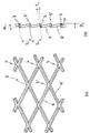
- the expanded metal expands the metal plate 3 by moving the upper teeth 1 of the expanding metal manufacturing machine up and down and left and right while making staggered cuts to form a diamond-shaped, turtle-shaped or fan-shaped opening. It is a metal net made up of. Specifically, (1) the metal plate 3 having a thickness T e is fed out on the lower blade 2 with a stepped width W e , and (2) the metal plate 3 is pressed by the holding tool 4, and the upper tooth 1 shifted to the right.
- SW e / (2 ⁇ W e ) is called the enlargement ratio.
- the expanded metal has a ridge formed by the bonds 5, 5'as shown in FIG.
- the metal plate used for the expanded metal include iron steel plates; non-iron metal plates such as stainless steel plates, aluminum plates, copper plates and titanium plates; alloy plates such as iron alloy plates, aluminum alloy plates, copper alloy plates and titanium alloy plates. be able to.
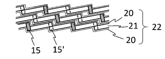
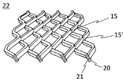
- the catalyst layer 20 is attached to the surface of the expanded metal 21 so as not to block the opening of the expanded metal.
- the catalyst layer preferably has a substantially constant thickness and is attached to the strands and bonds of the expanded metal.
- the average thickness d of the catalyst layer is preferably 10 to 200 ⁇ m, more preferably 20 to 80 ⁇ m.
- the catalyst component contained in the catalyst layer can be appropriately selected according to the chemical reaction to which the catalyst structure of the present invention is applied.
- an oxide of titanium, an oxide of molybdenum or tungsten and / or an oxide of vanadium can be used as a catalytic component (for example, Patent Document 1, Patent Document 2, Patent Document 3). , Patent Document 6 and the like).
- a catalyst component containing a noble metal such as platinum, palladium, iridium, rhodium and, if necessary, a carrier can be used as a catalyst component (see, for example, Patent Document 5).
- a catalyst component made by supporting Ni such as Ni / ZrO 2 and Ni / Al 2 O 3 on a carrier can be used.
- the catalyst layer can be formed by dip coating, spray coating, roller coating, curtain flow coating and the like. Of these, dip coating is preferred.
- the reticulated catalyst element used in the present invention has almost the same appearance as the expanded metal, and the strand portions 16, 16'and the bond portions 15, 15'are the strands 6, 6'and the bond 5, Compared to 5', the thickness of the catalyst layer is thicker.
- the reticulated catalyst element used in the present invention has a convex shape formed by the bond portions 15, 15'as shown in FIG. 5 or 11.
- the reticulated catalyst element used in the present invention has a plate thickness T c (that is, the sum of the plate thickness T e of the expanded metal and the average thickness d ⁇ 2 of the catalyst layer) and the total thickness D c (that is, the total thickness of the expanded metal).
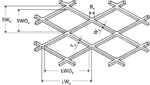
- Thickness De and average thickness d ⁇ 2 of the catalyst layer step size W c (that is, total thickness W e of expanded metal and average thickness d ⁇ 2 of the catalyst layer), short mesh eye direction center distance SW c (i.e., short-time direction center distance SW e of the expanded metal mesh), the openings short-time direction length SWO c (i.e., from the opening short-time direction length SWO e expanded metal (Value obtained by subtracting the average thickness d ⁇ 2 of the catalyst layer), the distance between the centers in the long direction of the mesh LW c (that is, the distance between the centers in the long direction of the expanded metal mesh LW e ), the length in the long direction of the opening LWO c (that is, the value obtained by subtracting the average thickness d ⁇ 2 of the catalyst layer from the opening length LWO e of the expanded metal), and the bond length B c (that is, the bond length B e of the expanded metal and the catalyst). It is not particularly limited by each size (total with
- the plate thickness T c is preferably 0.1 to 0.3 mm, more preferably 0.1 to 0.2 mm.
- the total thickness D c is preferably 0.5 to 3.0 mm, more preferably 0.5 to 2.0 mm.
- the step size W c is preferably 0.4 to 3.0 mm, more preferably 0.4 to 2.0 mm.
- the distance SW c between the centers in the short direction of the mesh is preferably 1.5 to 7 mm, more preferably 2 to 5 mm.
- the length SWO c in the short direction of the opening is preferably 0.8 to 3.0 mm, more preferably 1.0 to 2.0 mm.
- the distance LW c between the centers in the long direction of the mesh is preferably 3 to 10 mm, more preferably 4.5 to 9 mm.
- the length LWO c in the longitudinal direction of the opening is preferably 2 to 8 mm, more preferably 3 to 6 mm.
- the bond portion length B c is preferably 0.8 to 8 mm, more preferably 1.0 to 6.0 mm.
- Each size of the mesh of one reticulated catalyst element may be different from each size of each mesh of another adjacent reticulated catalyst element, or may be the same. From the viewpoint of production efficiency of the catalyst structure, it is preferable that all of the sizes are the same. In addition, “same” means within the fluctuation range which can be regarded as the same in practice.
- the reticulated catalyst element is cut in the direction parallel to the long direction at the bond part that matches the mesh (full mesh), and cut in the direction parallel to the short direction at the bond part that matches the mesh. It may be edge-treated by either (bond cutting) or cutting at a strand portion irrelevant to the mesh (random cutting). In addition, "parallel" means within a fluctuation range which can be regarded as parallel in practical use.
- the main surface of the reticulated catalyst element (the surface when the convex apex formed by the bond portion is assumed to be connected) is usually flat, but has a bent portion such as a triangular wave shape or a sinusoidal shape. It may be good (see FIG. 13).
- the bent portions (ridge line and valley line) of each reticulated catalyst element are fitted to each other so that the main surfaces face each other. (See FIG. 12).
- the method of stacking the reticulated catalyst elements is not particularly limited as long as the main surfaces of the reticulated catalyst elements face each other (see FIGS. 10 and 12).
- each reticulated catalyst element may be non-parallel to each other or parallel to each other. It is easier to secure a predetermined gap between the reticulated catalyst elements when they are non-parallel to each other than when they are parallel to each other.
- each reticulated catalyst element may be in the same direction or in the opposite direction.
- Reticulated catalyst elements of the same size are in contact with each other so that the mesh length directions of the reticulated catalyst elements are parallel to each other and the main surfaces (plate surfaces of the bond portions 15 and 15) of the original metal plates 3 of each reticulated catalyst element face each other.
- the meshes of the reticulated catalyst elements are almost aligned, and the convexity of the bond portion fits into the recess between the strand portion and the bond portion.
- a catalyst structure can be obtained (Fig. 6). This catalyst structure has a high density of reticulated catalyst elements, although the pressure loss is slightly high.
- Reticulated catalyst elements of the same size are parallel to each other in the mesh length direction of each reticulated catalyst element, the plate surfaces of the bond portions of each reticulated catalyst element face each other, but do not touch each other, and the inclination ⁇ of the strand portion is the same.
- the protrusions of the plurality of bond portions in one reticulated catalyst element are placed in the middle of the mesh of the other adjacent reticulated catalyst elements to support them.
- a predetermined gap is secured between each network catalyst element, and a catalyst structure having a structure in which one network appears to be divided into four networks having substantially similar shapes when projected from the normal direction of the network catalyst element is obtained. Can be done (Fig. 7).
- the reticulated catalyst elements of the same size are in contact with each other in parallel with each other in the mesh length direction of the reticulated catalyst elements, the protrusions of the bond portions of the reticulated catalyst elements face each other, and the inclination ⁇ of the strand portions is the same direction.
- the meshes of the reticulated catalyst elements are almost aligned, and the plurality of bond portions in one reticulated catalyst element come into contact with and support the bond portions of the other adjacent reticulated catalyst elements. Therefore, it is possible to obtain a catalyst structure in which a predetermined gap is secured between the reticulated catalyst elements (FIG. 8).
- a catalyst structure in which the mesh length directions of each reticulated catalyst element are overlapped so as to be non-parallel to each other is, for example, a solo vane (long long) expanded metal in which the long side of the edge is parallel to the mesh length direction.
- the reticulated catalyst element used and the reticulated catalyst element made of expanded metal whose short sides of the edges are parallel to the long side of the mesh are alternately overlapped and contacted with the long sides of the edges aligned. It can be obtained by making the mesh length directions of the reticulated catalyst elements perpendicular to each other. Further, it can be obtained by trimming each reticulated catalyst element so that the mesh length directions of the reticulated catalyst elements intersect each other at a predetermined angle.
- the catalyst structure formed by stacking the strands so that the inclination ⁇ is opposite to each other is obtained, for example, by stacking the back surface and the back surface or the front surface of each network catalyst element so as to face each other.
- the catalyst structure in which a plurality of the catalyst structures are alternately stacked is not particularly limited depending on the stacking method.
- the reticulated catalyst elements are subjected to a predetermined edge treatment so that the reticulated catalyst elements have the above-mentioned positional relationship.
- Each of the reticulated catalyst elements can be housed in a frame of a predetermined size to form a unit. The unitization can also facilitate the work at the time of installation and replacement in the flow reactor or exhaust heat recovery baila.
- the chances that the reaction substrate flowing through the gaps secured between the reticulated catalyst elements comes into contact with the catalyst layer increases, and the flow of the reaction substrate is not blocked by the strands, etc., and the pressure loss increases.
- the catalyst structure is robust because the reticulated catalyst elements are supported by the bond portion and are in contact with each other.
- the average spacing between the reticulated catalyst elements is preferably 300 to 1100% with respect to the plate thickness T c of the reticulated catalyst elements. Further, it is preferably 80 to 120% with respect to the total thickness D c of the reticulated catalyst element.
- the average spacing between the reticulated catalyst elements can be calculated by dividing the stacked thickness D s of the reticulated catalyst elements in the catalyst structure by the number of stacked N s of the reticulated catalyst elements.
- the flow reactor of the present invention comprises the catalyst structure of the present invention. More specifically, the flow reactor of the present invention is formed by installing the catalyst structure of the present invention in the middle of the flow path of the reaction substrate.
- the flow reactor of the present invention can be applied to either a gas phase reaction or a liquid phase reaction, but is preferably applied to a gas phase reaction. Examples of the flow reactor that performs the gas phase reaction include denitration equipment, VOC removal equipment, and CO removal equipment installed in the exhaust heat recovery boiler.
- the exhaust heat recovery boiler of the present invention has the catalyst structure of the present invention. More specifically, the exhaust heat recovery boiler of the present invention is formed by using the catalyst structure of the present invention in the denitration equipment, VOC removal equipment or CO removal equipment that may be installed in the exhaust heat recovery boiler. ..
- the heat recovery steam generator is usually an economizer that heats the water supply, an economizer that evaporates the water, a superheater that heats the wet steam above the saturation temperature to make it superheated steam, and a coal saver. Includes a water supply preheater to prevent condensation on the vessel.
- the heat recovery steam generator may further include a drum that separates steam and water.
- the exhaust heat recovery steam generator may be a vertical HRSG in which gas flows vertically across a horizontally installed heat transfer tube, or a horizontal HRSG in which gas flows horizontally across a vertically installed heat transfer tube. You may.
- the denitration equipment is installed in the exhaust heat recovery boiler at a location in the temperature range suitable for the NOx reduction reaction. For example, it can be installed between the economizer and the evaporator or between the evaporators divided into multiple stages.
- the denitration equipment sequentially includes a reducing agent supply unit and a denitration catalyst unit along the gas flow direction.
- the catalyst structure of the present invention is used for this denitration catalyst section.
- Ammonia is usually used as a reducing agent in the reducing agent supply unit.
- VOC or CO removal equipment is installed in the exhaust heat recovery boiler in a temperature zone suitable for the oxidation reaction of VOC or CO.
- VOC or CO equipment has a combustion catalyst part.
- the catalyst structure of the present invention is used for this combustion catalyst section.
- the catalyst structure contained in the exhaust heat recovery boiler of the present invention is not particularly limited by the angle formed by the long mesh direction or the short mesh direction and the gas flow direction.
- the angle formed by the long mesh direction and the gas flow direction may be 90 degrees, and the angle formed by both the short mesh direction and the gas flow direction may be 90 degrees, or the long mesh direction and the gas flow may be formed.
- the angle formed by the direction may be 0 degrees, the angle formed by the short mesh direction and the gas flow direction may be 0 degrees, or may be an intermediate angle between them.
- the angle formed by the mesh length direction and the gas flow direction of one net-like catalyst element is preferably -30 degrees or more and less than 0 degrees, more preferably.
- the angle between the mesh length direction and the gas flow direction of the other reticulated catalyst element adjacent to the -20 degrees or more and -10 degrees or less is preferably more than 0 degrees and +30 degrees or less, more preferably 10 degrees. It is 20 degrees or more and 20 degrees or less.
- Example 1 A flat expanded metal with a rhombic mesh was prepared by lath processing a steel plate. This expanded metal is trimmed into a rectangle of 500 mm x 150 mm so that the angle of the long side of the edge with respect to the long direction of the mesh is +10 degrees and -10 degrees, and a mesh element with an angle of +10 degrees and an angle of -10 degrees. Reticulated elements were obtained respectively. Each of these network elements is dip-coated with a catalyst solution containing platinum or the like so as not to block the mesh mesh to form a catalyst layer having a predetermined thickness, and the plate thickness T c is 0.15 mm and the mesh is short.
- a flat mesh catalyst element of a diamond-shaped mesh with a directional center distance SW c of 5 mm, a mesh long-direction center distance LW c of 9 mm, a step size W c of 2 mm, and a total thickness D c of 1.8 mm. was obtained respectively.
- the catalyst structure was obtained by stacking the layers until they became the same and filling the frame with internal dimensions of 150 mm ⁇ 150 mm ⁇ 500 mm. At least one of the plurality of bond portions in one reticulated catalyst element comes into contact with and supports another adjacent reticulated catalyst element, and a predetermined gap is secured between the reticulated catalyst elements.
- the average spacing between the reticulated catalyst elements was about 1.5 mm.
- a flow reactor was obtained by mounting a catalyst structure so that the long side of the edge was parallel to the gas flow direction of the duct.
- Example 2 A catalyst structure and a flow reactor were obtained in the same manner as in Example 1 except that the trimming angles were set to +20 degrees and -20 degrees.
- the number of stacks N s was 113.
- At least one of the plurality of bond portions in one reticulated catalyst element comes into contact with and supports another adjacent reticulated catalyst element, and a predetermined gap is secured between the reticulated catalyst elements.
- the average spacing between the reticulated catalyst elements was about 1.3 mm.
- Example 3 A flat expanded metal with a rhombic mesh was prepared by lath processing a steel plate. This expanded metal was trimmed into a rectangle of 500 mm ⁇ 150 mm so that the angle of the long side of the edge with respect to the long direction of the mesh was 0 degrees to obtain a mesh element having an angle of 0 degrees. A catalyst solution containing platinum or the like is dip-coated on this net-like element so as not to block the mesh mesh to form a catalyst layer having a predetermined thickness, and the plate thickness T c is 0.18 mm and the distance between the centers in the short direction.
- a frame having an inner size of 150 mm ⁇ 150 mm ⁇ 500 mm was filled to obtain a catalyst structure.
- the mesh of each reticulated catalyst element was almost aligned, the convexity of the bond portion was fitted exactly to the concave portion between the strand portion and the bond portion, and the reticulated catalyst element was filled with high density.
- the average spacing between the reticulated catalyst elements was about 0.4 mm.
- a flow reactor was obtained by mounting a catalyst structure so that the long side of the edge was parallel to the gas flow direction of the duct.
- Example 4 A flat expanded metal with a rhombic mesh was prepared by lath processing a steel plate. This expanded metal is trimmed into a rectangle of 500 mm x 150 mm so that the angle of the long side of the edge with respect to the long direction of the mesh is +10 degrees and -10 degrees, and a mesh element with an angle of +10 degrees and an angle of -10 degrees. Reticulated elements were obtained respectively. Each of these network elements is dip-coated with a catalyst solution containing platinum or the like so as not to block the mesh mesh to form a catalyst layer having a predetermined thickness, and the plate thickness T c is 0.18 mm and the mesh is short.
- the catalyst structure was obtained by stacking the layers until they became the same and filling the frame with internal dimensions of 150 mm ⁇ 150 mm ⁇ 500 mm. At least one of the plurality of bond portions in one reticulated catalyst element comes into contact with and supports another adjacent reticulated catalyst element, and a predetermined gap is secured between the reticulated catalyst elements. The average spacing between the reticulated elements was about 0.7 mm.
- a flow reactor was obtained by mounting a catalyst structure so that the long side of the edge was parallel to the gas flow direction of the duct.
- Example 5 A catalyst structure and a flow reactor were obtained in the same manner as in Example 4 except that the trimming angles were set to +20 degrees and -20 degrees. At a stacking thickness of D s 150 mm, the number of stacks N s was 229. At least one of the plurality of bond portions in one reticulated catalyst element comes into contact with and supports another adjacent reticulated catalyst element, and a predetermined gap is secured between the reticulated catalyst elements. The average spacing between the reticulated catalyst elements was about 0.7 mm.
- Example 6 A flat expanded metal with a rhombic mesh was prepared by lath processing a steel plate. This expanded metal was trimmed into a rectangle of 500 mm ⁇ 150 mm so that the angle of the long side of the edge with respect to the long direction of the mesh was 90 degrees to obtain a mesh element having an angle of 90 degrees. A catalyst solution containing platinum or the like is dip-coated on this net-like element so as not to block the mesh, and a catalyst layer having a predetermined thickness is formed. The plate thickness T c is 0.18 mm, and the center of the mesh in the short direction.
- a catalyst structure was obtained by filling a frame of ⁇ 500 mm. At least one of the plurality of bond portions in one reticulated catalyst element comes into contact with and supports another adjacent reticulated catalyst element, and a predetermined gap is secured between the reticulated catalyst elements. The average spacing between the reticulated catalyst elements was about 0.8 mm.
- a flow reactor was obtained by mounting a catalyst structure so that the long side of the edge was parallel to the gas flow direction of the duct.
- the present invention includes modifications, changes, and additions to each configuration of the catalyst structure, the flow reactor, and the exhaust heat recovery boiler within a range not contrary to the gist of the present invention.
- SW e short-time direction distance between the centers of the expanded metal mesh
- SWO e opening short-time length of the expanded metal
- T e thickness W e of the expanded metal (metal plate): increments of expanded metal width
- LW e the distance between the long grain direction center of the expanded metal mesh
- LWO e opening director grain direction length of the expanded metal
- D e the total thickness of the expanded metal
- B e bond lengths of expanded metal S e: press widened width
- SW c catalyst Distance between the centers in the short direction of the mesh of the element
- SWO c Length of the opening in the short direction of the catalyst element
- T c Plate thickness of the catalyst element
- W c Notch width of the catalyst element
- LW c Long direction of the mesh of the catalyst element Distance between centers
- LWO c Length in the direction of the opening of the catalyst element
Landscapes
- Chemical & Material Sciences (AREA)
- Engineering & Computer Science (AREA)
- Chemical Kinetics & Catalysis (AREA)
- Materials Engineering (AREA)
- Organic Chemistry (AREA)
- Environmental & Geological Engineering (AREA)
- Thermal Sciences (AREA)
- Combustion & Propulsion (AREA)
- Sustainable Energy (AREA)
- Physics & Mathematics (AREA)
- Life Sciences & Earth Sciences (AREA)
- Mechanical Engineering (AREA)
- General Engineering & Computer Science (AREA)
- Sustainable Development (AREA)
- Health & Medical Sciences (AREA)
- Biomedical Technology (AREA)
- Analytical Chemistry (AREA)
- General Chemical & Material Sciences (AREA)
- Oil, Petroleum & Natural Gas (AREA)
- Catalysts (AREA)
- Exhaust Gas Treatment By Means Of Catalyst (AREA)
Abstract
エキスパンドメタルと、エキスパンドメタルの開口部を塞がないように前記エキスパンドメタルに付着された触媒層とを含有してなる、網状触媒エレメントを、一の網状触媒エレメントに在る複数のボンド部のうちの少なくとも一つが隣接する他の一の網状触媒エレメントに接触して支えになって、各網状触媒エレメント間に所定の隙間が確保されるように、複数枚重ねてなる、触媒構造体。
Description
本発明は、触媒構造体およびそれを有するフロー式反応器または排熱回収ボイラに関する。
板状触媒をガスの流れに対して平行に重畳してなる触媒構造体が種々提案されている。
例えば、特許文献1は、平板状の触媒を交互に逆方向に折り曲げて階段状または波板状に成形した板状触媒を、平板状の網状物を介して多数積層した触媒構造体において、前記網状物としてメタルラス板を用い、該メタルラス板の板厚を、メタルラス加工前の金属板の板厚の1.2~3倍としたことを特徴とする排ガス浄化用触媒構造体を開示している。
例えば、特許文献1は、平板状の触媒を交互に逆方向に折り曲げて階段状または波板状に成形した板状触媒を、平板状の網状物を介して多数積層した触媒構造体において、前記網状物としてメタルラス板を用い、該メタルラス板の板厚を、メタルラス加工前の金属板の板厚の1.2~3倍としたことを特徴とする排ガス浄化用触媒構造体を開示している。
特許文献2は、所定間隔で帯状の凸状部を多数設けた、所定の目開き幅を有する網状基材と、該網状基材の目開き幅よりも大きい目開き幅を有する平板状の網状基材とを交互に多数積層した基材構造体と、該基材構造体の表面に、前記凸状部を設けた網状基材の網目を塞ぐとともに前記平板状網状基材の網目は貫通するように残して担持された触媒成分とを有することを特徴とする排ガス浄化用触媒構造体を開示している。
特許文献3は、基材表面に触媒成分を担持させた触媒エレメントを、表裏を貫通する孔を多数有する網状物を介して多数積層した排ガス浄化用触媒構造体であって、前記触媒エレメントが、平板状の触媒エレメントであり、前記網状物が、長方形または正方形の平板状網状物を、その一対の辺に対して平行な方向に所定間隔で逆方向に折り曲げて平板部と段差部を交互に形成した網状物、または前記一対の辺に対して平行な方向に所定間隔で波板状に湾曲させて山部と谷部を交互に形成した網状物であることを特徴とする排ガス浄化用触媒構造体を開示している。
特許文献4は、アルミナウィスカを生成する焼成条件にてラス加工されたアルミニウム含有耐熱金属薄板を熱処理して得られる基材に、排ガス浄化用触媒組成物を担持し、所定形状に成形した後、焼成することを特徴とする板状触媒の製造方法を開示している。
本発明の課題は、触媒構造体およびそれを有するフロー式反応器または排熱回収ボイラを提供することである。
上記課題を解決するために検討した結果、以下の形態を包含する本発明を完成するに至った。
〔1〕 エキスパンドメタルを含有してなる網状触媒エレメントを、
複数枚重ねてなる、
触媒構造体。
複数枚重ねてなる、
触媒構造体。
〔2〕 エキスパンドメタルと、エキスパンドメタルの開口部を塞がないように前記エキスパンドメタルに付着された触媒層とを含有してなる、網状触媒エレメントを、
複数枚重ねてなる、
触媒構造体。
〔3〕 触媒層が、酸化触媒または還元触媒を含む、〔2〕に記載の触媒構造体。
〔4〕 触媒層が、白金を含有する触媒を含む、〔2〕に記載の触媒構造体。
複数枚重ねてなる、
触媒構造体。
〔3〕 触媒層が、酸化触媒または還元触媒を含む、〔2〕に記載の触媒構造体。
〔4〕 触媒層が、白金を含有する触媒を含む、〔2〕に記載の触媒構造体。
〔5〕 一の網状触媒エレメントに在る複数のボンド部のうちの少なくとも一つが、それに隣接する他の一の網状触媒エレメントに接触して支えになって、各網状触媒エレメント間に所定の隙間が確保されている、〔1〕~〔4〕のいずれかひとつに記載の触媒構造体。
〔6〕 一の網状触媒エレメントに在る複数のボンド部のうちの少なくとも一つが、それに隣接する他の一の網状触媒エレメントのストランド部の中ほどまたはボンド部に接触して支えになって、各網状触媒エレメント間に所定の隙間が確保されている、〔1〕~〔4〕のいずれかひとつに記載の触媒構造体。
〔6〕 一の網状触媒エレメントに在る複数のボンド部のうちの少なくとも一つが、それに隣接する他の一の網状触媒エレメントのストランド部の中ほどまたはボンド部に接触して支えになって、各網状触媒エレメント間に所定の隙間が確保されている、〔1〕~〔4〕のいずれかひとつに記載の触媒構造体。
〔7〕 隣接する網状触媒エレメントのメッシュ長目方向が相互に非平行である、〔1〕~〔6〕のいずれかひとつに記載の触媒構造体。
〔8〕 隣接する網状触媒エレメントのメッシュ長目方向が相互に平行である、〔1〕~〔6〕のいずれかひとつに記載の触媒構造体。
〔8〕 隣接する網状触媒エレメントのメッシュ長目方向が相互に平行である、〔1〕~〔6〕のいずれかひとつに記載の触媒構造体。
〔9〕 一の網状触媒エレメントのメッシュの各サイズのうちの少なくとも一つが、隣接する他の一の網状触媒エレメントのメッシュのそれに対応するサイズと異なる、〔1〕~〔8〕のいずれかひとつに記載の触媒構造体。
〔10〕 一の網状触媒エレメントのメッシュの各サイズが、隣接する他の一の網状触媒エレメントのメッシュの各サイズとそれぞれ同じである、〔1〕~〔8〕のいずれかひとつに記載の触媒構造体。
〔10〕 一の網状触媒エレメントのメッシュの各サイズが、隣接する他の一の網状触媒エレメントのメッシュの各サイズとそれぞれ同じである、〔1〕~〔8〕のいずれかひとつに記載の触媒構造体。
〔11〕 〔1〕~〔10〕のいずれかひとつに記載の触媒構造体を有してなる、フロー式反応器。
〔12〕 〔1〕~〔10〕のいずれかひとつに記載の触媒構造体を有してなる、排熱回収ボイラ。
〔13〕 一の各網状触媒エレメントのメッシュ長目方向とガス流れ方向とが成す角度が-30度以上0度未満であり、それに隣接する他の一の網状触媒エレメントのメッシュ長目方向とガス流れ方向とが成す角度が0度超+30度以下である、〔12〕に記載の排熱回収ボイラ。
〔13〕 一の各網状触媒エレメントのメッシュ長目方向とガス流れ方向とが成す角度が-30度以上0度未満であり、それに隣接する他の一の網状触媒エレメントのメッシュ長目方向とガス流れ方向とが成す角度が0度超+30度以下である、〔12〕に記載の排熱回収ボイラ。
本発明の触媒構造体は、従来の板状触媒からなる触媒構造体に比べ安価に製造でき、フロー式反応器または排熱回収ボイラへの設置および交換が容易である。本発明の触媒構造体は、圧力損失が低く、且つ固液接触系若しくは固気接触系における境膜が薄いので、本発明のフロー式反応器は、種々の化学反応、特に気相化学反応を高効率で触媒できる。本発明のフロー式反応器においては、反応を高効率で触媒できるので、白金などの高価な触媒成分の使用量を少なくしても、従来のフロー式反応器と同程度の反応速度を維持でき、コストの削減に寄与できる。本発明のフロー式反応器または排熱回収ボイラ(HRSG)によれば、例えば、揮発性有機化合物(VOC)の酸化反応、一酸化炭素の酸化反応、窒素酸化物の還元反応などを高効率で行うことができる。本発明によれば、例えば、ガスタービンコンバインドサイクル(GTCC)発電プラントの排ガスの浄化処理を、GTCC発電プラントの発電効率を低下させずに、低いコストで且つ高い効率で行うことができる。
本発明の触媒構造体は、網状触媒エレメントを複数枚重ねてなるものである。
本発明に用いられる網状触媒エレメントは、エキスパンドメタルを含有してなるものである。本発明に用いられる好ましい網状触媒エレメントは、エキスパンドメタル、および触媒層を含有してなるものである。
本発明に用いられる網状触媒エレメントは、エキスパンドメタルを含有してなるものである。本発明に用いられる好ましい網状触媒エレメントは、エキスパンドメタル、および触媒層を含有してなるものである。
エキスパンドメタルは、図3に示すように、金属板3をエキスパンドメタル製造機の上歯1の上下動および左右動によって千鳥状に切れ目を入れながら押し広げて菱形、亀甲形または扇形の開口部にして成る金属網である。具体的には、(1)厚さTeの金属板3を下刃2上に刻み幅Weにて繰り出し、(2)押さえ具4で金属板3を押さえ、右にシフトした上歯1を下向動させて、切れ目を入れながら押し広げ幅Seにて切れ目を押し広げ、(3)上歯1を上向動させ、(4)押さえ具4を外し、金属板3を下刃2上に刻み幅Weにて繰り出し、(5)押さえ具4で金属板3を押さえ、左にシフトした上歯1を下向動させて、切れ目を入れながら押し広げ幅Seにて切れ目を押し広げ、次いで(6)上歯1を上向動させる。このようにして、図1に示すような、全厚Deのエキスパンドメタルを得ることができる。このエキスパンドメタルは、主面(ボンドによって形成される凸の頂を繋いだと仮想したときの面)が、角度θ(=tan-1(Se/We))にて、元の金属板3の主面(ボンド5,5’の板面)に対して、傾斜している。なお、SWe/(2×We)は引伸率と呼ばれる。その結果、エキスパンドメタルは、図1に示すように、ボンド5,5’によって形成される凸を有する。エキスパンドメタルに用いられる金属板としては、鉄製鋼板;ステンレス鋼板、アルミニウム板、銅板、チタン板等の非鉄金属板;鉄合金板、アルミニウム合金板、銅合金板、チタン合金板などの合金板を挙げることができる。
触媒層20は、エキスパンドメタルの開口部を塞がないようにエキスパンドメタル21の表面に付着している。触媒層はほぼ一定の厚さでエキスパンドメタルのストランドおよびボンドに付着していることが好ましい。触媒層の平均厚さdは、好ましくは10~200μm、より好ましくは20~80μmである。
触媒層に含まれる触媒成分は、本発明の触媒構造体を適用する化学反応に応じて適宜選択することができる。例えば、接触還元脱硝反応においては、チタンの酸化物、モリブデンまたはタングステンの酸化物または/およびバナジウムの酸化物などを触媒成分として用いることができる(例えば、特許文献1、特許文献2、特許文献3、特許文献6などを参照)。一酸化炭素酸化反応においては、白金、パラジウム、イリジウム、ロジウムなどの貴金属などと必要に応じて担体とを含むものを触媒成分として用いることができる(例えば、特許文献5などを参照)。一酸化炭素や二酸化炭素からメタン、メタノールなどへの反応においては、Ni/ZrO2,Ni/Al2O3などのNiを担体に担持させて成る触媒成分を用いることができる。
触媒層は、ディップコーティング、スプレーコーティング、ローラコーティング、カーテンフローコーティングなどによって形成することができる。これらのうち、ディップコーティングが好ましい。
触媒層は、ディップコーティング、スプレーコーティング、ローラコーティング、カーテンフローコーティングなどによって形成することができる。これらのうち、ディップコーティングが好ましい。
本発明に用いられる網状触媒エレメントは、図4に示すように、エキスパンドメタルとほぼ同じ外観を有し、ストランド部16,16’およびボンド部15,15’がストランド6,6’およびボンド5,5’に比べて触媒層の厚さだけ太くなっている。本発明に用いられる網状触媒エレメントは、図5または図11に示すように、ボンド部15,15’によって形成される凸を有する。
本発明に用いられる網状触媒エレメントは、板厚Tc(すなわち、エキスパンドメタルの板厚Teと触媒層の平均厚さd×2との合計)、全厚Dc(すなわち、エキスパンドメタルの全厚Deと触媒層の平均厚さd×2との合計)、刻み幅Wc(すなわち、エキスパンドメタルの板厚Weと触媒層の平均厚さd×2との合計)、メッシュの短目方向中心間距離SWc(すなわち、エキスパンドメタルのメッシュの短目方向中心間距離SWe)、開口部短目方向長さSWOc(すなわち、エキスパンドメタルの開口部短目方向長さSWOeから触媒層の平均厚さd×2を差し引いた値)、メッシュの長目方向中心間距離LWc(すなわち、エキスパンドメタルのメッシュの長目方向中心間距離LWe)、開口部長目方向長さLWOc(すなわち、エキスパンドメタルの開口部長目方向長さLWOeから触媒層の平均厚さd×2を差し引いた値)、およびボンド部長さBc(すなわち、エキスパンドメタルのボンド長さBeと触媒層の平均厚さd×2との合計)などの各サイズによって特に制限されない。
例えば、板厚Tcは、好ましくは0.1~0.3mm、より好ましくは0.1~0.2mmである。
例えば、全厚Dcは、好ましくは0.5~3.0mm、より好ましくは0.5~2.0mmである。
例えば、刻み幅Wcは、好ましくは0.4~3.0mm、より好ましくは0.4~2.0mmである。
例えば、メッシュの短目方向中心間距離SWcは、好ましくは1.5~7mm、より好ましくは2~5mmである。
例えば、開口部短目方向長さSWOcは、好ましくは0.8~3.0mm、より好ましくは1.0~2.0mmである。
例えば、メッシュの長目方向中心間距離LWcは、好ましくは3~10mm、より好ましくは4.5~9mmである。
例えば、開口部長目方向長さLWOcは、好ましくは2~8mm、より好ましくは3~6mmである。
例えば、ボンド部長さBcは、好ましくは0.8~8mm、より好ましくは1.0~6.0mmである。
例えば、全厚Dcは、好ましくは0.5~3.0mm、より好ましくは0.5~2.0mmである。
例えば、刻み幅Wcは、好ましくは0.4~3.0mm、より好ましくは0.4~2.0mmである。
例えば、メッシュの短目方向中心間距離SWcは、好ましくは1.5~7mm、より好ましくは2~5mmである。
例えば、開口部短目方向長さSWOcは、好ましくは0.8~3.0mm、より好ましくは1.0~2.0mmである。
例えば、メッシュの長目方向中心間距離LWcは、好ましくは3~10mm、より好ましくは4.5~9mmである。
例えば、開口部長目方向長さLWOcは、好ましくは2~8mm、より好ましくは3~6mmである。
例えば、ボンド部長さBcは、好ましくは0.8~8mm、より好ましくは1.0~6.0mmである。
一の網状触媒エレメントのメッシュの各サイズは、隣接する他の一の網状触媒エレメントのメッシュの各サイズとそれぞれ異なっていてもよいし、それそれ同じであってもよい。触媒構造体の製造効率の観点からは、各サイズのすべてが同じであることが好ましい。なお、「同じ」とは、実用上同じと見做せる変動範囲内を意味する。
網状触媒エレメントは、メッシュの目に合わせたボンド部での長目方向に平行な方向での切断(フルメッシュ)、メッシュの目に合わせたボンド部での短目方向に平行な方向での切断(ボンド切断)、またはメッシュの目に関係なしのストランド部での切断(乱切断)のいずれの切断で縁処理されたものであってもよい。なお、「平行」とは、実用上平行と見做せる変動範囲内を意味する。
網状触媒エレメントの主面(ボンド部によって形成される凸の頂を繋いだと仮想したときの面)は、通常、平らであるが、三角波状、正弦波状などの折り曲げ部を有するものであってもよい(図13参照)。なお、触媒構造体に折り曲げ部を有する網状触媒エレメントを用いる場合は、主面が相互に向かい合うようにするために、各網状触媒エレメントの折り曲げ部(稜線と谷線と)が相互に嵌り合うようにすることが好ましい(図12参照)。
本発明の触媒構造体において、網状触媒エレメントの重ね方は、各網状触媒エレメントの主面が相互に向かい合うようにする限り、特に限定されない(図10、図12参照)。
各網状触媒エレメントのメッシュ長目方向は、相互に非平行であってもよいし、相互に平行であってもよい。相互に非平行である方が、相互に平行であるよりも、各網状触媒エレメント間に所定の隙間が確保されやすい。
また、各網状触媒エレメントのストランド部の傾きθが同じ向きになっていてもよいし、逆向きになっていてもよい。
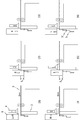
同じサイズの網状触媒エレメントを、各網状触媒エレメントのメッシュ長目方向を相互に平行に、各網状触媒エレメントの元の金属板3の主面(ボンド部15,15の板面)が向かい合って接し、且つストランド部の傾きθが同じ向きになるように、重ねると、各網状触媒エレメントの網目がほぼ揃い、ボンド部の凸がストランド部とボンド部との間にある凹に嵌って(fit)なる触媒構造体を得ることができる(図6)。この触媒構造体は、圧力損失は若干高いが、網状触媒エレメントを高密度で有する。
同じサイズの網状触媒エレメントを、各網状触媒エレメントのメッシュ長目方向を相互に平行に、各網状触媒エレメントのボンド部の板面が向かい合うが、接しないようにし、且つストランド部の傾きθが同じ向きになるように、網状触媒エレメントを重ねると、一の網状触媒エレメントに在る複数のボンド部の凸が、隣接する他の一の網状触媒エレメントのメッシュの中ほどに載って支えになり、各網状触媒エレメント間に所定の隙間が確保され、網状触媒エレメントの法線方向からの投影において一の網目がほぼ相似形状の四つの網目に分割されたように見える構造を有する触媒構造体を得ることができる(図7)。
さらに、同じサイズの網状触媒エレメントを、各網状触媒エレメントのメッシュ長目方向を相互に平行に、各網状触媒エレメントのボンド部の凸が向かい合って接し、且つストランド部の傾きθが同じ向きになるように、網状触媒エレメントを重ねると、各網状触媒エレメントの網目がほぼ揃い、一の網状触媒エレメントに在る複数ボンド部が、隣接する他の一の網状触媒エレメントのボンド部に接触して支えになり、各網状触媒エレメント間に所定の隙間が確保された触媒構造体を得ることができる(図8)。
同じサイズの網状触媒エレメントを、各網状触媒エレメントのメッシュ長目方向を相互に非平行になるように、網状触媒エレメントを重ねると、一の網状触媒エレメントに在る複数のボンド部のうちの少なくとも一つが隣接する他の一の網状触媒エレメントに接触して支えになって各網状触媒エレメント間に所定の隙間が確保された触媒構造体を得ることができる。
各網状触媒エレメントのメッシュ長目方向を相互に非平行になるように重ねて成る触媒構造体は、例えば、縁の長辺がメッシュ長目方向と平行となるソロバン目(longlong)」エキスパンドメタルを用いてなる網状触媒エレメントと縁の短辺がメッシュ長目方向と平行となる「タタミ目(shortlong)」エキスパンドメタルを用いてなる網状触媒エレメントとを縁の長辺をそろえて交互に重ねて接触させて、各網状触媒エレメントのメッシュ長目方向が相互に直角となるようにすることで得ることができる。また、網状触媒エレメントのメッシュ長目方向が所定の角度で相互に交差するように、各網状触媒エレメントをトリミングすることで得ることができる。
同じサイズの網状触媒エレメントを、各網状触媒エレメントのストランド部の傾きθが逆向きになるように、網状触媒エレメントを重ねると、一の網状触媒エレメントに在る複数のボンド部のうちの少なくとも一つが隣接する他の一の網状触媒エレメントに接触して支えになって各網状触媒エレメント間に所定の隙間が確保された触媒構造体を得ることができる(図9)。
ストランド部の傾きθが逆向きになるように重ねて成る触媒構造体は、例えば、各網状触媒エレメントの裏面と裏面または表面と表面が向かい合うように重ねることによって得られる。
異なるサイズの網状触媒エレメントを重ねると、一方の網状触媒エレメントに在る複数のボンド部のうちの少なくとも一つが他方の網状触媒エレメントに突き当たり支えとなるので、異なる2種のメッシュサイズの網状触媒エレメントを交互に複数枚重ねて成る触媒構造体は、その重ね方によって特に限定されない。
このような重ね方の状態を維持するために、各網状触媒エレメントの縁を揃えたときに、各網状触媒エレメントが上記のような位置関係になるように、各網状触媒エレメントに所定の縁処理を施して、所定の大きさの枠に各網状触媒エレメントを収納してユニット化することができる。ユニット化によって、フロー式反応器または排熱回収バイラへの設置、交換時の作業を容易にすることもできる。
以上のようにして重ねることによって、網状触媒エレメント間に確保された隙間を流れる反応基質が触媒層に接触する機会が増え、且つ反応基質の流れがストランド部等によって遮られず圧力損失の上昇を抑えることができ、一方で各網状触媒エレメントがボンド部に支えられて相互に接触しているので触媒構造体は堅牢である。
本発明の触媒構造体は、網状触媒エレメント間の平均間隔が、網状触媒エレメントの板厚Tcに対して、好ましくは300~1100%である。また、網状触媒エレメントの全厚Dcに対して、好ましくは80~120%である。なお、網状触媒エレメント間の平均間隔は、触媒構造体における網状触媒エレメントの積上げ厚さDsを網状触媒エレメントの積上げ枚数Nsで除することによって算出することができる。
本発明のフロー式反応器は、本発明の触媒構造体を有してなるものである。より具体的に、本発明のフロー式反応器は、反応基質の流路の途中に本発明の触媒構造体を設置してなるものである。本発明のフロー式反応器は、気相反応または液相反応のいずれにも適用可能であるが、気相反応への適用が好ましい。気相反応を行うフロー式反応器として、例えば、排熱回収ボイラに設置される、脱硝設備、VOC除去設備、CO除去設備などを挙げることができる。
本発明の排熱回収ボイラは、本発明の触媒構造体を有してなるものである。より具体的に、本発明の排熱回収ボイラは、排熱回収ボイラに設置されることがある脱硝設備、VOC除去設備またはCO除去設備に、本発明の触媒構造体を用いてなるものである。排熱回収ボイラは、通常、給水を加熱する節炭器(エコノマイザ)、水を蒸発させる蒸発器、湿り蒸気を蒸気タービンに送るために飽和温度以上に加熱し過熱蒸気とする過熱器、節炭器での結露を防ぐための給水予熱器を含む。排熱回収ボイラは、蒸気と水を分離するドラムをさらに含むことがある。排熱回収ボイラは、水平に設置された伝熱管を横切ってガスが垂直に流れる縦型HRSGであってもよいし、垂直に設置された伝熱管を横切ってガスが水平に流れる横型HRSGであってもよい。
脱硝設備は、排熱回収ボイラ内の、NOxの還元反応に適した温度帯となる箇所に設置される。例えば、節炭器と蒸発器との間または多段に分けた蒸発器の間に設置することができる。一般に、脱硝設備は、ガス流れ方向に沿って、還元剤供給部と、脱硝触媒部とを順次有する。この脱硝触媒部に、本発明の触媒構造体を用いる。還元剤供給部では、通常、アンモニアが還元剤として用いられる。
VOCまたはCO除去設備は、排熱回収ボイラ内の、VOCまたはCOの酸化反応に適した温度帯となる箇所に設置される。一般に、VOCまたはCO設備は、燃焼触媒部を有する。この燃焼触媒部に、本発明の触媒構造体を用いる。
本発明の排熱回収ボイラに有する触媒構造体は、メッシュ長目方向またはメッシュ短目方向とガス流れ方向との成す角度によって、特に制限されない。例えば、メッシュ長目方向とガス流れ方向との成す角度が90度で且つメッシュ短目方向の両者とガス流れ方向との成す角度が90度であってもよいし、メッシュ長目方向とガス流れ方向との成す角度が0度であってもよいし、メッシュ短目方向とガス流れ方向との成す角度が0度であってもよいし、それらの中間の角度であってもよい。
本発明の排熱回収ボイラに有する好ましい形態の触媒構造体において、一の網状触媒エレメントはメッシュ長目方向とガス流れ方向との成す角度が、好ましくは-30度以上0度未満、より好ましくは-20度以上-10度以下であり、それに隣接する他の一の網状触媒エレメントはメッシュ長目方向とガス流れ方向との成す角度が、好ましくは0度超+30度以下、より好ましくは10度以上20度以下である。このような角度でガスを流すと低い圧力損失で且つ触媒層との高い接触効率を実現させやすい。
次に実施例を示して、本発明をより詳細に説明する。ただし、本発明はこれら実施例によってその範囲が制限されない。
実施例1
鋼板をラス加工して菱形メッシュの平らなエキスパンドメタルを用意した。このエキスパンドメタルを、メッシュの長目方向に対する縁の長辺の角度が+10度および-10度となるように、500mm×150mmの長方形にトリミングして、角度+10度の網状エレメントおよび角度-10度の網状エレメントをそれぞれ得た。これら網状エレメントのそれぞれに白金などを含む触媒液をメッシュの目を塞がないようにディップコーティングして所定厚さの触媒層を形成させて、板厚Tcが0.15mm、メッシュの短目方向中心間距離SWcが5mmで、メッシュの長目方向中心間距離LWcが9mmで、刻み幅Wcが2mmで、全厚Dcが1.8mmである菱形メッシュの平らな網状触媒エレメントをそれぞれ得た。
鋼板をラス加工して菱形メッシュの平らなエキスパンドメタルを用意した。このエキスパンドメタルを、メッシュの長目方向に対する縁の長辺の角度が+10度および-10度となるように、500mm×150mmの長方形にトリミングして、角度+10度の網状エレメントおよび角度-10度の網状エレメントをそれぞれ得た。これら網状エレメントのそれぞれに白金などを含む触媒液をメッシュの目を塞がないようにディップコーティングして所定厚さの触媒層を形成させて、板厚Tcが0.15mm、メッシュの短目方向中心間距離SWcが5mmで、メッシュの長目方向中心間距離LWcが9mmで、刻み幅Wcが2mmで、全厚Dcが1.8mmである菱形メッシュの平らな網状触媒エレメントをそれぞれ得た。
ストランド部の傾きθが同じ向きになるように、角度+10度の網状触媒エレメントと角度-10度の網状触媒エレメントとを交互に、積上げ厚さDsが150mm(積上げ枚数Ns=102枚)となるまで重ね、内寸150mm×150mm×500mmの枠に充填して、触媒構造体を得た。一の網状触媒エレメントに在る複数のボンド部のうちの少なくとも一つが隣接する他の一の網状触媒エレメントに接触して支えになって、各網状触媒エレメント間に所定の隙間が確保された。網状触媒エレメント間の平均間隔は約1.5mmであった。縁の長辺がダクトのガス流れ方向と平行になるように触媒構造体を装着してフロー式反応器を得た。
実施例2
トリミング時の角度を+20度および-20度となるようにした以外は、実施例1と同じ方法で、触媒構造体およびフロー式反応器を得た。積上げ厚さDs150mmにおいて積上げ枚数Nsは113枚であった。一の網状触媒エレメントに在る複数のボンド部のうちの少なくとも一つが隣接する他の一の網状触媒エレメントに接触して支えになって、各網状触媒エレメント間に所定の隙間が確保された。網状触媒エレメント間の平均間隔が約1.3mmであった。
トリミング時の角度を+20度および-20度となるようにした以外は、実施例1と同じ方法で、触媒構造体およびフロー式反応器を得た。積上げ厚さDs150mmにおいて積上げ枚数Nsは113枚であった。一の網状触媒エレメントに在る複数のボンド部のうちの少なくとも一つが隣接する他の一の網状触媒エレメントに接触して支えになって、各網状触媒エレメント間に所定の隙間が確保された。網状触媒エレメント間の平均間隔が約1.3mmであった。
実施例3
鋼板をラス加工して菱形メッシュの平らなエキスパンドメタルを用意した。このエキスパンドメタルを、メッシュの長目方向に対する縁の長辺の角度が0度となるように、500mm×150mmの長方形にトリミングして、角度0度の網状エレメントを得た。この網状エレメントに白金などを含む触媒液をメッシュの目を塞がないようにディップコーティングして所定厚さの触媒層を形成させて、板厚Tcが0.18mm、短目方向中心間距離SWcが2mmで、メッシュの長目方向中心間距離LWcが4.5mmで、刻み幅Wcが0.47mmで、全厚Dcが0.7mmである菱形メッシュの平らな網状触媒エレメントを得た。
鋼板をラス加工して菱形メッシュの平らなエキスパンドメタルを用意した。このエキスパンドメタルを、メッシュの長目方向に対する縁の長辺の角度が0度となるように、500mm×150mmの長方形にトリミングして、角度0度の網状エレメントを得た。この網状エレメントに白金などを含む触媒液をメッシュの目を塞がないようにディップコーティングして所定厚さの触媒層を形成させて、板厚Tcが0.18mm、短目方向中心間距離SWcが2mmで、メッシュの長目方向中心間距離LWcが4.5mmで、刻み幅Wcが0.47mmで、全厚Dcが0.7mmである菱形メッシュの平らな網状触媒エレメントを得た。
ストランド部の傾きθが同じ向きに、ボンド部の板面が向かい合って接するように角度0度の網状触媒エレメントを、積上げ厚さDsが150mm(積上げ枚数Ns=422枚)となるまで重ね、内寸150mm×150mm×500mmの枠に充填して、触媒構造体を得た。各網状触媒エレメントの網目がほぼ揃い、ボンド部の凸がストランド部とボンド部との間にある凹にぴったり嵌っており、網状触媒エレメントが高密度に充填されていた。網状触媒エレメント間の平均間隔が約0.4mmであった。縁の長辺がダクトのガス流れ方向と平行になるように触媒構造体を装着してフロー式反応器を得た。
実施例4
鋼板をラス加工して菱形メッシュの平らなエキスパンドメタルを用意した。このエキスパンドメタルを、メッシュの長目方向に対する縁の長辺の角度が+10度および-10度となるように、500mm×150mmの長方形にトリミングして、角度+10度の網状エレメントおよび角度-10度の網状エレメントをそれぞれ得た。これら網状エレメントのそれぞれに白金などを含む触媒液をメッシュの目を塞がないようにディップコーティングして所定厚さの触媒層を形成させて、板厚Tcが0.18mm、メッシュの短目方向中心間距離SWcが2mmで、メッシュの長目方向中心間距離LWcが4.5mmで、刻み幅Wcが0.47mmで、全厚Dcが0.7mmである菱形メッシュの平らな網状触媒エレメントをそれぞれ得た。
鋼板をラス加工して菱形メッシュの平らなエキスパンドメタルを用意した。このエキスパンドメタルを、メッシュの長目方向に対する縁の長辺の角度が+10度および-10度となるように、500mm×150mmの長方形にトリミングして、角度+10度の網状エレメントおよび角度-10度の網状エレメントをそれぞれ得た。これら網状エレメントのそれぞれに白金などを含む触媒液をメッシュの目を塞がないようにディップコーティングして所定厚さの触媒層を形成させて、板厚Tcが0.18mm、メッシュの短目方向中心間距離SWcが2mmで、メッシュの長目方向中心間距離LWcが4.5mmで、刻み幅Wcが0.47mmで、全厚Dcが0.7mmである菱形メッシュの平らな網状触媒エレメントをそれぞれ得た。
ストランド部の傾きθが同じ向きになるように、角度+10度の網状触媒エレメントと角度-10度の網状触媒エレメントとを交互に、積上げ厚さDsが150mm(積上げ枚数Ns=207枚)となるまで重ね、内寸150mm×150mm×500mmの枠に充填して、触媒構造体を得た。一の網状触媒エレメントに在る複数のボンド部のうちの少なくとも一つが隣接する他の一の網状触媒エレメントに接触して支えになって、各網状触媒エレメント間に所定の隙間が確保された。網状エレメント間の平均間隔が約0.7mmであった。縁の長辺がダクトのガス流れ方向と平行になるように触媒構造体を装着してフロー式反応器を得た。
実施例5
トリミング時の角度を+20度および-20度となるようにした以外は、実施例4と同じ方法で、触媒構造体およびフロー式反応器を得た。積上げ厚さDs150mmにおいて積上げ枚数Nsは229枚であった。一の網状触媒エレメントに在る複数のボンド部のうちの少なくとも一つが隣接する他の一の網状触媒エレメントに接触して支えになって、各網状触媒エレメント間に所定の隙間が確保された。網状触媒エレメント間の平均間隔が約0.7mmであった。
トリミング時の角度を+20度および-20度となるようにした以外は、実施例4と同じ方法で、触媒構造体およびフロー式反応器を得た。積上げ厚さDs150mmにおいて積上げ枚数Nsは229枚であった。一の網状触媒エレメントに在る複数のボンド部のうちの少なくとも一つが隣接する他の一の網状触媒エレメントに接触して支えになって、各網状触媒エレメント間に所定の隙間が確保された。網状触媒エレメント間の平均間隔が約0.7mmであった。
実施例6
鋼板をラス加工して菱形メッシュの平らなエキスパンドメタルを用意した。このエキスパンドメタルを、メッシュの長目方向に対する縁の長辺の角度が90度となるように500mm×150mmの長方形にトリミングして、角度90度の網状エレメントを得た。この網状エレメントに白金などを含む触媒液をメッシュの目を塞がないようにディップコーティングして所定厚さの触媒層を形成させて、板厚Tcが0.18mm、メッシュの短目方向中心間距離SWcが2mmで、メッシュの長目方向中心間距離LWcが4.5mmで、刻み幅Wcが0.47mmで、全厚Dcが0.7mmである菱形メッシュの平らな網状触媒エレメントを得た。
鋼板をラス加工して菱形メッシュの平らなエキスパンドメタルを用意した。このエキスパンドメタルを、メッシュの長目方向に対する縁の長辺の角度が90度となるように500mm×150mmの長方形にトリミングして、角度90度の網状エレメントを得た。この網状エレメントに白金などを含む触媒液をメッシュの目を塞がないようにディップコーティングして所定厚さの触媒層を形成させて、板厚Tcが0.18mm、メッシュの短目方向中心間距離SWcが2mmで、メッシュの長目方向中心間距離LWcが4.5mmで、刻み幅Wcが0.47mmで、全厚Dcが0.7mmである菱形メッシュの平らな網状触媒エレメントを得た。
ストランド部の傾きθが逆向きになるように、角度90度の網状触媒エレメントを交互に、積上げ厚さDsが150mm(積上げ枚数Ns=194枚)となるまで重ね、内寸150mm×150mm×500mmの枠に充填して、触媒構造体を得た。一の網状触媒エレメントに在る複数のボンド部のうちの少なくとも一つが隣接する他の一の網状触媒エレメントに接触して支えになって、各網状触媒エレメント間に所定の隙間が確保された。網状触媒エレメント間の平均間隔が約0.8mmであった。縁の長辺がダクトのガス流れ方向と平行になるように触媒構造体を装着してフロー式反応器を得た。
〔圧力損失の測定〕
表1に示す条件にて実施例1~6で得られたフロー式反応器を用いて触媒構造体の圧力損失を測定した。実施例3で得られた触媒構造体の圧力損失の測定値を基準した実施例1~2および4~6で得られた触媒構造体の圧力損失の測定値の比(厚損比)をそれぞれ算出した。結果を表2に示す。
表1に示す条件にて実施例1~6で得られたフロー式反応器を用いて触媒構造体の圧力損失を測定した。実施例3で得られた触媒構造体の圧力損失の測定値を基準した実施例1~2および4~6で得られた触媒構造体の圧力損失の測定値の比(厚損比)をそれぞれ算出した。結果を表2に示す。


本発明は、本発明の趣旨に反しない範囲で、触媒構造体、フロー反応器または排熱回収ボイラの各構成を、修正、変更、追加したものを包含する。
SWe:エキスパンドメタルのメッシュの短目方向中心間距離
SWOe:エキスパンドメタルの開口部短目方向長さ
Te:エキスパンドメタル(金属板)の板厚
We:エキスパンドメタルの刻み幅
LWe:エキスパンドメタルのメッシュの長目方向中心間距離
LWOe:エキスパンドメタルの開口部長目方向長さ
De:エキスパンドメタルの全厚
Be:エキスパンドメタルのボンド長さ
Se:押し広げ幅
SWc:触媒エレメントのメッシュの短目方向中心間距離
SWOc:触媒エレメントの開口部短目方向長さ
Tc:触媒エレメントの板厚
Wc:触媒エレメントの刻み幅
LWc:触媒エレメントのメッシュの長目方向中心間距離
LWOc:触媒エレメントの開口部長目方向長さ
Dc:触媒エレメントの全厚
Bc:触媒エレメントのボンド部長さ
1:上歯
2:下歯
3:金属板
4:押さえ具
5、5’:ボンド
6、6’:ストランド
L:上歯左シフト
R:上歯右シフト
15、15’:ボンド部
16、16’:ストランド部
20:触媒層
21:エキスパンドメタル
22:平らな網状触媒エレメント
22’:三角波状の網状触媒エレメント
23:ガス流
24:枠
SWOe:エキスパンドメタルの開口部短目方向長さ
Te:エキスパンドメタル(金属板)の板厚
We:エキスパンドメタルの刻み幅
LWe:エキスパンドメタルのメッシュの長目方向中心間距離
LWOe:エキスパンドメタルの開口部長目方向長さ
De:エキスパンドメタルの全厚
Be:エキスパンドメタルのボンド長さ
Se:押し広げ幅
SWc:触媒エレメントのメッシュの短目方向中心間距離
SWOc:触媒エレメントの開口部短目方向長さ
Tc:触媒エレメントの板厚
Wc:触媒エレメントの刻み幅
LWc:触媒エレメントのメッシュの長目方向中心間距離
LWOc:触媒エレメントの開口部長目方向長さ
Dc:触媒エレメントの全厚
Bc:触媒エレメントのボンド部長さ
1:上歯
2:下歯
3:金属板
4:押さえ具
5、5’:ボンド
6、6’:ストランド
L:上歯左シフト
R:上歯右シフト
15、15’:ボンド部
16、16’:ストランド部
20:触媒層
21:エキスパンドメタル
22:平らな網状触媒エレメント
22’:三角波状の網状触媒エレメント
23:ガス流
24:枠
Claims (13)
- エキスパンドメタルを含有してなる網状触媒エレメントを、
複数枚重ねてなる、
触媒構造体。 - エキスパンドメタルと、エキスパンドメタルの開口部を塞がないように前記エキスパンドメタルに付着された触媒層とを含有してなる、網状触媒エレメントを、
複数枚重ねてなる、
触媒構造体。 - 触媒層が、酸化触媒または還元触媒を含む、請求項2に記載の触媒構造体。
- 触媒層が、白金を含有する触媒を含む、請求項2に記載の触媒構造体。
- 一の網状触媒エレメントに在る複数のボンド部のうちの少なくとも一つが、それに隣接する他の一の網状触媒エレメントに接触して支えになって、各網状触媒エレメント間に所定の隙間が確保されている、請求項1~4のいずれかひとつに記載の触媒構造体。
- 一の網状触媒エレメントに在る複数のボンド部のうちの少なくとも一つが、それに隣接する他の一の網状触媒エレメントのストランド部の中ほどまたはボンド部に接触して支えになって、各網状触媒エレメント間に所定の隙間が確保されている、請求項1~4のいずれかひとつに記載の触媒構造体。
- 隣接する網状触媒エレメントのメッシュ長目方向が相互に非平行である、請求項1~6のいずれかひとつに記載の触媒構造体。
- 隣接する網状触媒エレメントのメッシュ長目方向が相互に平行である、請求項1~6のいずれかひとつに記載の触媒構造体。
- 一の網状触媒エレメントのメッシュの各サイズのうちの少なくとも一つが、隣接する他の一の網状触媒エレメントのメッシュのそれに対応するサイズと異なる、請求項1~8のいずれかひとつに記載の触媒構造体。
- 一の網状触媒エレメントのメッシュの各サイズが、隣接する他の一の網状触媒エレメントのメッシュの各サイズとそれぞれ同じである、請求項1~8のいずれかひとつに記載の触媒構造体。
- 請求項1~10のいずれかひとつに記載の触媒構造体を有してなる、フロー式反応器。
- 請求項1~10のいずれかひとつに記載の触媒構造体を有してなる、排熱回収ボイラ。
- 一の網状触媒エレメントはメッシュ長目方向とガス流れ方向との成す角度が-30度以上0度未満であり、それに隣接する他の一の網状触媒エレメントはメッシュ長目方向とガス流れ方向との成す角度が0度超+30度以下である、請求項12に記載の排熱回収ボイラ。
Applications Claiming Priority (2)
| Application Number | Priority Date | Filing Date | Title |
|---|---|---|---|
| JP2019-132670 | 2019-07-18 | ||
| JP2019132670A JP2021016812A (ja) | 2019-07-18 | 2019-07-18 | 触媒構造体およびそれを有するフロー式反応器または排熱回収ボイラ |
Publications (1)
| Publication Number | Publication Date |
|---|---|
| WO2021010486A1 true WO2021010486A1 (ja) | 2021-01-21 |
Family
ID=74210936
Family Applications (1)
| Application Number | Title | Priority Date | Filing Date |
|---|---|---|---|
| PCT/JP2020/027946 Ceased WO2021010486A1 (ja) | 2019-07-18 | 2020-07-17 | 触媒構造体およびそれを有するフロー式反応器または排熱回収ボイラ |
Country Status (2)
| Country | Link |
|---|---|
| JP (1) | JP2021016812A (ja) |
| WO (1) | WO2021010486A1 (ja) |
Citations (5)
| Publication number | Priority date | Publication date | Assignee | Title |
|---|---|---|---|---|
| JPH0459054A (ja) * | 1990-06-21 | 1992-02-25 | Babcock Hitachi Kk | 排ガス浄化用触媒および排ガスの浄化方法 |
| JP2002361092A (ja) * | 2001-06-06 | 2002-12-17 | Babcock Hitachi Kk | 排ガス脱硝用触媒スラリ、脱硝用触媒およびそれらの製造方法 |
| WO2005051517A1 (ja) * | 2003-11-25 | 2005-06-09 | Babcock-Hitachi Kabushiki Kaisha | ディーゼルエンジン排ガス用フィルタ |
| JP2007252640A (ja) * | 2006-03-23 | 2007-10-04 | Orion Mach Co Ltd | 吸着浄化装置 |
| JP2019005697A (ja) * | 2017-06-23 | 2019-01-17 | カーリットホールディングス株式会社 | 触媒カートリッジ |
-
2019
- 2019-07-18 JP JP2019132670A patent/JP2021016812A/ja active Pending
-
2020
- 2020-07-17 WO PCT/JP2020/027946 patent/WO2021010486A1/ja not_active Ceased
Patent Citations (5)
| Publication number | Priority date | Publication date | Assignee | Title |
|---|---|---|---|---|
| JPH0459054A (ja) * | 1990-06-21 | 1992-02-25 | Babcock Hitachi Kk | 排ガス浄化用触媒および排ガスの浄化方法 |
| JP2002361092A (ja) * | 2001-06-06 | 2002-12-17 | Babcock Hitachi Kk | 排ガス脱硝用触媒スラリ、脱硝用触媒およびそれらの製造方法 |
| WO2005051517A1 (ja) * | 2003-11-25 | 2005-06-09 | Babcock-Hitachi Kabushiki Kaisha | ディーゼルエンジン排ガス用フィルタ |
| JP2007252640A (ja) * | 2006-03-23 | 2007-10-04 | Orion Mach Co Ltd | 吸着浄化装置 |
| JP2019005697A (ja) * | 2017-06-23 | 2019-01-17 | カーリットホールディングス株式会社 | 触媒カートリッジ |
Also Published As
| Publication number | Publication date |
|---|---|
| JP2021016812A (ja) | 2021-02-15 |
Similar Documents
| Publication | Publication Date | Title |
|---|---|---|
| JP4293569B2 (ja) | 触媒構造体と被処理ガス浄化装置 | |
| US6534022B1 (en) | Conversion of nitrogen oxides in the presence of a catalyst supported on a mesh-like structure | |
| JP2003512150A5 (ja) | ||
| JPWO1996014920A1 (ja) | 触媒構造体と被処理ガス浄化装置 | |
| US6667017B2 (en) | Process for removing environmentally harmful compounds | |
| RU2005127663A (ru) | Способ и инструмент для изготовления профилированных металлических листов, а также носитель каталитического нейтрализатора | |
| BR0210943B1 (pt) | Reator catalítico, processo para realizar reforma metano/vapor, e, planta para o processamento de metano para produzir hidrocarbonetos de cadeia mais longa | |
| KR20070008648A (ko) | 제거형 촉매 구조체를 갖는 플레이트형 반응기 | |
| BRPI0708113A2 (pt) | estrutura de catalisador, método para fabricar a mesma, e, reator catalìtico compacto | |
| US9757720B2 (en) | Catalyst having a three-dimensional dent structure in the form of a hexagon | |
| CN104781005B (zh) | 废气净化用催化剂结构体 | |
| JP5312991B2 (ja) | 反応装置およびシート状部材 | |
| JP2021016812A (ja) | 触媒構造体およびそれを有するフロー式反応器または排熱回収ボイラ | |
| US6260606B1 (en) | Rotor construction for air preheater | |
| JP2021115538A (ja) | 脱硝触媒構造体 | |
| JP2008284506A (ja) | 排ガス浄化用触媒及びその製造方法と排ガスの処理方法 | |
| JP7154082B2 (ja) | 排ガス浄化用触媒構造体 | |
| JP7195094B2 (ja) | 排ガス浄化用触媒構造体 | |
| JP6490966B2 (ja) | 板状脱硝触媒及びその製造方法 | |
| JP2006026606A (ja) | 触媒反応装置 | |
| JP2014050824A (ja) | 排ガス浄化用触媒エレメントおよび排ガス浄化用触媒構造体 | |
| JP5198744B2 (ja) | 触媒構造体 | |
| JP2014113569A (ja) | 排ガス浄化用触媒構造体 | |
| JP5491342B2 (ja) | 排ガス処理用触媒および触媒構造体 | |
| WO2013093422A1 (en) | Catalyst structure and a catalytic process |
Legal Events
| Date | Code | Title | Description |
|---|---|---|---|
| 121 | Ep: the epo has been informed by wipo that ep was designated in this application |
Ref document number: 20841412 Country of ref document: EP Kind code of ref document: A1 |
|
| NENP | Non-entry into the national phase |
Ref country code: DE |
|
| 122 | Ep: pct application non-entry in european phase |
Ref document number: 20841412 Country of ref document: EP Kind code of ref document: A1 |