WO2021010331A1 - 発光性化合物又はその塩、並びにこれを含む偏光発光素子、偏光発光板、及び表示装置 - Google Patents
発光性化合物又はその塩、並びにこれを含む偏光発光素子、偏光発光板、及び表示装置 Download PDFInfo
- Publication number
- WO2021010331A1 WO2021010331A1 PCT/JP2020/027058 JP2020027058W WO2021010331A1 WO 2021010331 A1 WO2021010331 A1 WO 2021010331A1 JP 2020027058 W JP2020027058 W JP 2020027058W WO 2021010331 A1 WO2021010331 A1 WO 2021010331A1
- Authority
- WO
- WIPO (PCT)
- Prior art keywords
- group
- polarized light
- light emitting
- formula
- salt
- Prior art date
- Legal status (The legal status is an assumption and is not a legal conclusion. Google has not performed a legal analysis and makes no representation as to the accuracy of the status listed.)
- Ceased
Links
Classifications
-
- C—CHEMISTRY; METALLURGY
- C07—ORGANIC CHEMISTRY
- C07D—HETEROCYCLIC COMPOUNDS
- C07D277/00—Heterocyclic compounds containing 1,3-thiazole or hydrogenated 1,3-thiazole rings
- C07D277/60—Heterocyclic compounds containing 1,3-thiazole or hydrogenated 1,3-thiazole rings condensed with carbocyclic rings or ring systems
- C07D277/84—Naphthothiazoles
-
- C—CHEMISTRY; METALLURGY
- C07—ORGANIC CHEMISTRY
- C07C—ACYCLIC OR CARBOCYCLIC COMPOUNDS
- C07C309/00—Sulfonic acids; Halides, esters, or anhydrides thereof
- C07C309/01—Sulfonic acids
- C07C309/28—Sulfonic acids having sulfo groups bound to carbon atoms of six-membered aromatic rings of a carbon skeleton
- C07C309/45—Sulfonic acids having sulfo groups bound to carbon atoms of six-membered aromatic rings of a carbon skeleton containing nitrogen atoms, not being part of nitro or nitroso groups, bound to the carbon skeleton
- C07C309/51—Sulfonic acids having sulfo groups bound to carbon atoms of six-membered aromatic rings of a carbon skeleton containing nitrogen atoms, not being part of nitro or nitroso groups, bound to the carbon skeleton at least one of the nitrogen atoms being part of any of the groups, X being a hetero atom, Y being any atom
-
- C—CHEMISTRY; METALLURGY
- C07—ORGANIC CHEMISTRY
- C07D—HETEROCYCLIC COMPOUNDS
- C07D249/00—Heterocyclic compounds containing five-membered rings having three nitrogen atoms as the only ring hetero atoms
- C07D249/16—Heterocyclic compounds containing five-membered rings having three nitrogen atoms as the only ring hetero atoms condensed with carbocyclic rings or ring systems
- C07D249/18—Benzotriazoles
- C07D249/20—Benzotriazoles with aryl radicals directly attached in position 2
-
- C—CHEMISTRY; METALLURGY
- C07—ORGANIC CHEMISTRY
- C07D—HETEROCYCLIC COMPOUNDS
- C07D249/00—Heterocyclic compounds containing five-membered rings having three nitrogen atoms as the only ring hetero atoms
- C07D249/16—Heterocyclic compounds containing five-membered rings having three nitrogen atoms as the only ring hetero atoms condensed with carbocyclic rings or ring systems
- C07D249/22—Naphthotriazoles
-
- C—CHEMISTRY; METALLURGY
- C07—ORGANIC CHEMISTRY
- C07D—HETEROCYCLIC COMPOUNDS
- C07D277/00—Heterocyclic compounds containing 1,3-thiazole or hydrogenated 1,3-thiazole rings
- C07D277/60—Heterocyclic compounds containing 1,3-thiazole or hydrogenated 1,3-thiazole rings condensed with carbocyclic rings or ring systems
- C07D277/62—Benzothiazoles
- C07D277/64—Benzothiazoles with only hydrocarbon or substituted hydrocarbon radicals attached in position 2
- C07D277/66—Benzothiazoles with only hydrocarbon or substituted hydrocarbon radicals attached in position 2 with aromatic rings or ring systems directly attached in position 2
-
- C—CHEMISTRY; METALLURGY
- C09—DYES; PAINTS; POLISHES; NATURAL RESINS; ADHESIVES; COMPOSITIONS NOT OTHERWISE PROVIDED FOR; APPLICATIONS OF MATERIALS NOT OTHERWISE PROVIDED FOR
- C09K—MATERIALS FOR MISCELLANEOUS APPLICATIONS, NOT PROVIDED FOR ELSEWHERE
- C09K11/00—Luminescent materials, e.g. electroluminescent or chemiluminescent
- C09K11/06—Luminescent materials, e.g. electroluminescent or chemiluminescent containing organic luminescent materials
-
- G—PHYSICS
- G02—OPTICS
- G02B—OPTICAL ELEMENTS, SYSTEMS OR APPARATUS
- G02B1/00—Optical elements characterised by the material of which they are made; Optical coatings for optical elements
- G02B1/10—Optical coatings produced by application to, or surface treatment of, optical elements
- G02B1/14—Protective coatings, e.g. hard coatings
-
- G—PHYSICS
- G02—OPTICS
- G02B—OPTICAL ELEMENTS, SYSTEMS OR APPARATUS
- G02B5/00—Optical elements other than lenses
- G02B5/30—Polarising elements
-
- C—CHEMISTRY; METALLURGY
- C09—DYES; PAINTS; POLISHES; NATURAL RESINS; ADHESIVES; COMPOSITIONS NOT OTHERWISE PROVIDED FOR; APPLICATIONS OF MATERIALS NOT OTHERWISE PROVIDED FOR
- C09K—MATERIALS FOR MISCELLANEOUS APPLICATIONS, NOT PROVIDED FOR ELSEWHERE
- C09K2211/00—Chemical nature of organic luminescent or tenebrescent compounds
- C09K2211/10—Non-macromolecular compounds
- C09K2211/1003—Carbocyclic compounds
- C09K2211/1007—Non-condensed systems
-
- C—CHEMISTRY; METALLURGY
- C09—DYES; PAINTS; POLISHES; NATURAL RESINS; ADHESIVES; COMPOSITIONS NOT OTHERWISE PROVIDED FOR; APPLICATIONS OF MATERIALS NOT OTHERWISE PROVIDED FOR
- C09K—MATERIALS FOR MISCELLANEOUS APPLICATIONS, NOT PROVIDED FOR ELSEWHERE
- C09K2211/00—Chemical nature of organic luminescent or tenebrescent compounds
- C09K2211/10—Non-macromolecular compounds
- C09K2211/1003—Carbocyclic compounds
- C09K2211/1011—Condensed systems
-
- C—CHEMISTRY; METALLURGY
- C09—DYES; PAINTS; POLISHES; NATURAL RESINS; ADHESIVES; COMPOSITIONS NOT OTHERWISE PROVIDED FOR; APPLICATIONS OF MATERIALS NOT OTHERWISE PROVIDED FOR
- C09K—MATERIALS FOR MISCELLANEOUS APPLICATIONS, NOT PROVIDED FOR ELSEWHERE
- C09K2211/00—Chemical nature of organic luminescent or tenebrescent compounds
- C09K2211/10—Non-macromolecular compounds
- C09K2211/1003—Carbocyclic compounds
- C09K2211/1014—Carbocyclic compounds bridged by heteroatoms, e.g. N, P, Si or B
-
- C—CHEMISTRY; METALLURGY
- C09—DYES; PAINTS; POLISHES; NATURAL RESINS; ADHESIVES; COMPOSITIONS NOT OTHERWISE PROVIDED FOR; APPLICATIONS OF MATERIALS NOT OTHERWISE PROVIDED FOR
- C09K—MATERIALS FOR MISCELLANEOUS APPLICATIONS, NOT PROVIDED FOR ELSEWHERE
- C09K2211/00—Chemical nature of organic luminescent or tenebrescent compounds
- C09K2211/10—Non-macromolecular compounds
- C09K2211/1018—Heterocyclic compounds
- C09K2211/1025—Heterocyclic compounds characterised by ligands
- C09K2211/1029—Heterocyclic compounds characterised by ligands containing one nitrogen atom as the heteroatom
- C09K2211/1037—Heterocyclic compounds characterised by ligands containing one nitrogen atom as the heteroatom with sulfur
-
- C—CHEMISTRY; METALLURGY
- C09—DYES; PAINTS; POLISHES; NATURAL RESINS; ADHESIVES; COMPOSITIONS NOT OTHERWISE PROVIDED FOR; APPLICATIONS OF MATERIALS NOT OTHERWISE PROVIDED FOR
- C09K—MATERIALS FOR MISCELLANEOUS APPLICATIONS, NOT PROVIDED FOR ELSEWHERE
- C09K2211/00—Chemical nature of organic luminescent or tenebrescent compounds
- C09K2211/10—Non-macromolecular compounds
- C09K2211/1018—Heterocyclic compounds
- C09K2211/1025—Heterocyclic compounds characterised by ligands
- C09K2211/1059—Heterocyclic compounds characterised by ligands containing three nitrogen atoms as heteroatoms
Definitions
- the present invention relates to a novel luminescent compound or a salt thereof, a polarized light emitting device containing the same, a polarized light emitting plate, and a display device (display).
- a polarizing plate having a light transmitting and / or shielding function is a basic component of a display device such as a liquid crystal display (LCD) together with a liquid crystal having a light switching function.
- LCD liquid crystal display
- the fields of application of this LCD are expanding from small devices such as calculators and watches in the early days to notebook computers, word processors, liquid crystal projectors, liquid crystal televisions, car navigation systems, indoor and outdoor measuring devices, and the like. It can also be applied to lenses having a polarizing function, and for example, it has been applied to sunglasses with improved visibility and polarized glasses compatible with 3D televisions in recent years.
- the applications of the polarizing plate are wide-ranging, and the usage environment is wide, such as low temperature to high temperature, low humidity to high humidity, low light amount to high light amount, etc., so that it has high polarization performance and high durability.
- a polarizing plate is required.
- the polarizing film constituting the polarizing plate is produced by stretching and orienting a film of polyvinyl alcohol or a derivative thereof containing iodine or a dichroic dye, or dehydroxic acid or polyvinyl alcohol of a polyvinyl chloride film. It is produced by producing and orienting polyene by dehydrating the system film.
- a polarizing plate composed of such a conventional polarizing film contains a dichroic dye having absorption in the visible region, so that the transmittance is lowered.
- the transmittance of a general polarizing plate on the market is 35 to 45%.
- Patent Document 1 describes a technique for a polarizing plate for ultraviolet rays as a technique for providing a polarizing function while maintaining a certain degree of transmittance in the visible region, in response to the problem of a conventional polarizing plate in which the transmittance in the visible region is lowered. Has been done. However, this technique also uses a yellow pigment that absorbs in the visible region, so that the transmittance is not sufficient and a strong yellow coloring is confirmed.
- the polarized light emitting elements described in Patent Documents 2 to 4 are expensive because they contain special metals such as lanthanoids and europium, which have high rare values, and are extremely difficult to manufacture for mass production. Not suitable. Further, these polarized light emitting elements are difficult to use in a display because the light emission of polarized light is weak, and the emitted light which is linearly polarized light cannot be obtained. Therefore, we will develop a new polarized light emitting plate and materials for it that show polarized light emitting action, are highly transparent in the visible light range, and can be applied to liquid crystal displays that are required to be durable in harsh environments. Is desired.
- An object of the present application is to provide a novel luminescent compound, a polarized light emitting device containing the luminescent compound, a polarized light emitting plate, and a display device.
- a polarized light emitting element and a polarized light emitting plate containing a compound having a specific structure or a salt thereof have a high two-color ratio in the ultraviolet region. It has been found that it exhibits high transmittance in the visible light region and also exhibits excellent durability in a harsh environment. Further, a compound having such a specific structure or a salt thereof exhibits an action of emitting polarized light in the visible light region by irradiation with light in the ultraviolet to near-ultraviolet visible region, for example, light of 300 to 430 nm.
- the present invention has been completed.
- the present invention relates to, but is not limited to: [Invention 1]
- X and Y are independently selected from the group consisting of a group represented by the above formula (2), a heterocyclic group containing a nitrogen atom or a sulfur atom, and a nitro group. Except when both X and Y are nitro groups; or (ii) at least one of X and Y (independently in both cases) has a nitro group, a substituent.
- Amino group an alkyl group of C1 to 4 which may have a substituent, an alkoxy group of C1 to 4 which may have a substituent, an aromatic group which may have a substituent, and a substituent.
- the luminescent compound according to Invention 1 which is selected from the group consisting of substituents represented by.
- A independently has a hydrogen atom, a halogen group, a nitro group, a hydroxy group, an alkyl group of C1 to 4, an alkoxy group of C1 to 4, and a sulfo group.
- N 1 and n 2 each independently represent an integer of 0 to 3, and * in the above formulas (3) to (7) is the coupling position in X or Y of the above formula (1), or , Indicates the bonding position in Z of the above formula (2)).
- X and Y in the above formula (1) are independently selected from the group consisting of substituents represented by the formulas (2) to (7), and when the formula (2) is selected, Z is the formula (3). )-(7) The luminescent compound according to Invention 1 or 2, or a salt thereof, selected from the group consisting of substituents.
- both X and Y are selected from the group consisting of substituents represented by the formulas (2) to (7), and when the formula (2) is selected, Z is the formula (3).
- invention 13 A polarized light emitting plate provided with a transparent protective film on at least one surface of the polarized light emitting device according to any one of the inventions 9 to 12.
- invention 14 A display device including the polarized light emitting device according to any one of Inventions 9 to 12 or the polarized light emitting plate according to Invention 13.
- the luminescent compound having a specific structure according to the present invention or a salt thereof absorbs light in the ultraviolet to visible region, for example, light in the ultraviolet to near ultraviolet visible region, specifically, light having a diameter of 300 to 430 nm, and its energy. Shows a polarized light emitting effect in the visible light region.
- the polarizing element and the polarizing plate produced by using the luminescent compound or a salt thereof are a novel polarized light emitting element and a polarized light emitting plate exhibiting a polarized light emitting action.
- the luminescent compound or salt thereof according to the present invention and the polarized light emitting element and the polarized light emitting plate containing the same show a high degree of polarization at the absorption wavelength. Therefore, by using the compound represented by the formula (1) or a salt thereof, it has a high degree of polarization at the absorption wavelength and exhibits a polarized light emitting effect without using a lanthanoid metal having a high rare value.
- a novel polarized light emitting element and a polarized light emitting plate can be provided.
- the polarized light emitting device and the polarized light emitting plate according to the present invention exhibit high transmittance in the visible region.
- the polarized light emitting device and the polarized light emitting plate according to the present invention exhibit excellent durability against heat, humidity and the like. Therefore, the polarized light emitting element and the polarized light emitting plate can be applied to a display device such as a liquid crystal display which is required to have high transparency in the visible light region and high durability in a harsh environment.
- substituted includes a hydrogen atom for convenience.
- the phrase “may have a substituent” means that a case without a substituent is also included.
- a "phenyl group which may have a substituent” includes a simple phenyl group which is not substituted and a phenyl group which has a substituent.
- Luminescent compound The luminescent compound or a salt thereof according to the present invention is represented by the above formula (1).
- “luminescent compound or salt thereof” may be simply abbreviated as “luminescent compound”.
- X and Y are each independently selected from the group consisting of the group represented by the above formula (2), a heterocyclic group containing a nitrogen atom or a sulfur atom, and a nitro group. Except when both X and Y are nitro groups; or (ii) at least one of X and Y (independently in both cases) has a nitro group, a substituent. It has an amino group which may have an amino group, an alkyl group of C1 to 4 (which may have 1 to 4 carbon atoms) which may have a substituent, an alkoxy group of C1 to 4 which may have a substituent, and a substituent.
- M independently represents a hydrogen atom, a metal ion, or an ammonium ion, m independently represents an integer of 0 to 2, and s is 0 or 1.
- Z is a phenyl group which may have a substituent, a naphthyl group which may have a substituent, and a substitution. It is selected from the group consisting of a stillben group which may have a group, a benzoyl group which may have a substituent, and a heterocyclic group which may have a substituent, and t represents an integer of 0 or 1.
- amino group which may have a substituent examples include amino group; methylamino group, ethylamino group, n-butylamino group, phenylamino group, naphthylamino group and acetyl.
- Mono-substituted amino groups such as amino groups (ie, acetamide groups); di-substituted amino groups such as dimethylamino group, diethylamino group, di-n-butylamino group, diphenylamino group, ethylmethylamino group, ethylphenylamino group; etc.
- the above formula (2) described later is also included in the amino group which may have a substituent.
- alkyl group of C1-4 examples include methyl group, ethyl group, n-propyl group and iso-. Examples thereof include a propyl group, an n-butyl group, a sec-butyl group, a tert-butyl group and a cyclobutyl group.
- alkoxy group of C1-4 examples include a methoxy group, an ethoxy group, an n-propoxy group, and iso-. Examples thereof include a propoxy group, an n-butoxy group, a sec-butoxy group, a tert-butoxy group, a cyclobutoxy group and the like.
- heterocyclic group containing a nitrogen atom or a sulfur atom in the definition of X and Y represents a heterocycle having at least one of a nitrogen atom and a sulfur atom as a ring component, and may have the above-mentioned "substituted group".
- a “heterocyclic group containing an oxygen atom, a nitrogen atom or a sulfur atom” of a “heterocyclic group containing a good oxygen atom, a nitrogen atom or a sulfur atom” means that at least one of an oxygen atom, a nitrogen atom and a sulfur atom is a ring component. Represents a heterocycle having as.
- heterocyclic groups containing an oxygen atom, a nitrogen atom or a sulfur atom include a pyrrole group, a benzopyrrole group, a thiophene group, a benzothiophene group, a thiazole group, a benzothiazole group, a naphthoazole group, a triazole group and a benzo.
- examples thereof include a triazole group, a naphthotriazole group, a thiadiazole group, a benzothiazol group, and a pyridine group.
- amino group which may have a substituent "alkyl group of C1 to 4 which may have a substituent”, "alkoxy group of C1 to 4 which may have a substituent", "substitution”.
- the substituent in the "aromatic group which may have a group” and the "heterocyclic group containing an oxygen atom, a nitrogen atom or a sulfur atom which may have a substituent” is not particularly limited, but for example. Examples thereof include a hydroxy group, a cyano group, a phosphoric acid group, a sulfo group, a carboxy group and an amino group.
- the "amino group which may have a substituent” may further have a substituent as exemplified herein.
- M independently represents a hydrogen atom, a metal ion, or an ammonium ion.
- the metal ion include alkali metal ions such as lithium ion, sodium ion and potassium ion, and alkaline earth metal ions such as calcium ion and magnesium ion.
- ammonium ions for example, narrow ammonium ion (NH 4 +), methylammonium ion, dimethylammonium ion, triethylammonium ion, tetraethylammonium ion, tetra -n- propyl ammonium ion, tetra -n- butyl ammonium ion, mono- Examples thereof include ethanolammonium ion, diethanolammonium ion, triethanolammonium ion, monoisopropanolammonium ion, diisopropanolammonium ion, triisopropanolammonium ion, and triethanolammonium ion.
- narrow ammonium ion NH 4 +
- methylammonium ion dimethylammonium ion
- triethylammonium ion tetraethylammonium ion
- M is a hydrogen atom
- sulfonic acid -SO 3 H
- sodium sulfonate -SO 3 Na
- ammonium ion Represents ammonium sulfonate (-SO 3 NH 4 ), respectively.
- lithium ion, ammonium ion, and sodium ion are preferable.
- * indicates a bond position in X and / or Y in the formula (1)
- Z is a phenyl group which may have a substituent, and a naphthyl group which may have a substituent. It is selected from the group consisting of a stillben group which may have a substituent, a benzoyl group which may have a substituent, and a heterocyclic group which may have a substituent.
- t represents an integer of 0 or 1.
- heterocyclic group which may have a substituent in the definition of Z includes, for example, "an oxygen atom, a nitrogen atom which may have a substituent” in the definition of X and Y of the above formula (1). It may be the same as the "heterocyclic group containing a sulfur atom", and may be a furan group, a benzofuran group or the like containing an oxygen atom as a ring component.
- Preferred substituents of the above-mentioned "phenyl group which may have a substituent” in the definition of Z include an alkoxy group of C1 to 4, a nitro group, a sulfo group, and a substitution represented by the formulas (3) to (7).
- Groups are mentioned, and preferred substituents of the above-mentioned "naphthyl group which may have a substituent” in the definition of Z include hydroxy group, sulfo group, nitro group, and C1-4 alkoxy group having a sulfo group.
- the preferred substituent of the above-mentioned "stillben group which may have a substituent" in the definition of Z is a sulfo group, a nitro group, an amino group which may have a substituent, and formulas (3) to (7).
- preferable substituents of the above-mentioned "benzoyl group which may have a substituent” in the definition of Z include a sulfo group, a nitro group and the like, and the above in the definition of Z.
- Preferred substituents of the "heterocyclic group which may have a substituent” include a sulfo group, a halogen group, a hydroxy group, an alkyl group of C1 to 4, an alkoxy group of C1 to 4, and C1 to 4 having a sulfo group.
- halogen group in the definition of Z include a fluorine group, a chlorine group, a bromine group, an iodine group and the like.
- alkyl group of C1-4 in the definition of Z include methyl group, ethyl group, n-propyl group, iso-propyl group, n-butyl group, sec-butyl group, tert-butyl group and cyclobutyl. Group etc. can be mentioned.
- alkoxy group of C1 to 4" in the definition of Z examples include methoxy group, ethoxy group, n-propoxy group, iso-propoxy group, n-butoxy group, sec-butoxy group, tert-butoxy group and cyclo. Examples thereof include a butoxy group.
- alkyl group of C1-4 having a sulfo group examples include those having a sulfo group, a hydroxy group, or a carboxy group as a substituent at an arbitrary position of "to 4 alkyl groups”.
- alkoxy group of C1-4 having a sulfo group examples include those having a sulfo group, a hydroxy group, or a carboxy group as a substituent at an arbitrary position of "to 4 alkoxy groups”.
- At least one of X and Y in the above formula (1) and Z in the above formula (2) when at least one of X and Y is represented by the above formula (2) is the above formulas (3) to (7). It is preferably selected from the group consisting of substituents represented by.
- A independently has a hydrogen atom, a halogen group, a nitro group, a hydroxy group, an alkyl group of C1 to 4, an alkoxy group of C1 to 4, and a sulfo group.
- q 1 represents an integer of 0 to 4
- M in the above formulas (3) to (7) is defined by the above formula (1).
- N 1 and n 2 each independently represent an integer of 0 to 3
- * in the above equations (3) to (7) is the coupling position in X or Y of the above equation (1), respectively.
- the bonding position in Z of the above formula (2) is shown.
- alkyl group of C1-4 examples include methyl group, ethyl group, n-propyl group, iso-propyl group, n-butyl group, sec-butyl group, tert-butyl group and cyclobutyl. Group etc. can be mentioned.
- alkyl group of C1-4 having a sulfo group examples include a sulfomethyl group, a sulfoethyl group, a sulfo-n-propyl group, a sulfo-n-butyl group, a sulfo-sec-butyl group and the like. Can be mentioned.
- halogen group in the definition of A include a fluorine group, a chlorine group, a bromine group, an iodine group and the like.
- alkoxy group of C1 to 4" in the definition of A examples include methoxy group, ethoxy group, n-propoxy group, iso-propoxy group, n-butoxy group, sec-butoxy group, tert-butoxy group and cyclo. Examples thereof include a butoxy group.
- alkyl group of C1-4 having a hydroxy group in the definition of A includes, for example, a hydroxymethyl group, a hydroxyethyl group, a hydroxy-n-propyl group, a hydroxy-iso-propyl group, and a hydroxy-n-butyl group. , Hydroxy-sec-butyl group, hydroxy-tert-butyl group, hydroxycyclobutyl group and the like.
- alkyl group of C1-4 having a carboxy group in the definition of A includes, for example, a carboxymethyl group, a carboxyethyl group, a carboxy-n-propyl group, a carboxy-iso-propyl group, and a carboxy-n-butyl group. , Carboxy-sec-butyl group, carboxy-tert-butyl group, carboxycyclobutyl group and the like.
- alkoxy group of C1-4 having a sulfo group in the definition of A includes, for example, a sulfomethoxy group, a sulfoethoxy group, a sulfo-n-propoxy group, a sulfo-iso-propoxy group, and a sulfo-n-butoxy group. , Sulfo-sec-butoxy group, sulfo-tert-butoxy group, sulfocyclobutoxy group and the like.
- alkoxy group of C1 to 4 having a hydroxy group examples include a hydroxymethoxy group, a hydroxyethoxy group, a hydroxy-n-propoxy group, a hydroxy-iso-propoxy group, and a hydroxy-n-butoxy group. , Hydroxy-sec-butoxy group, hydroxy-tert-butoxy group, hydroxycyclobutoxy group and the like.
- alkoxy group of C1-4 having a carboxy group in the definition of A includes, for example, a carboxymethoxy group, a carboxyethoxy group, a carboxy-n-propoxy group, a carboxy-iso-propoxy group, and a carboxy-n-butoxy group. , Carboxy-sec-butoxy group, carboxy-tert-butoxy group, carboxycyclobutoxy group and the like.
- At least one of X and Y in the above formula (1) is selected from the group consisting of substituents represented by the formulas (2) to (7), and Z when the formula (2) is selected. Is selected from the group consisting of substituents represented by the formulas (3) to (7). More preferably, X and Y in the above formula (1) are independently selected from the group consisting of substituents represented by the formulas (2) to (7), and Z when the formula (2) is selected. Is selected from the group consisting of substituents represented by the formulas (3) to (7). More preferably, X and Y in the above formula (1) are both selected from the group consisting of substituents represented by the formulas (2) to (7), and when the formula (2) is selected, Z is selected. It is selected from the group consisting of substituents represented by the formulas (3) to (7).
- each m is 0.
- s is 0.
- s is 1.
- the above formula (1) is represented by the above formula (1').
- X and Y are as defined in the above formula (1), respectively.
- each of X, Y, M, and m is as defined in the above formula (1).
- Equation (8), (8-A), and (8-B) X, Y, M, and m are as defined in equation (1).
- the compound represented by the above formula (1) or a salt thereof is useful as a compound capable of emitting polarized light.
- the compound represented by the formula (1) or a salt thereof may be combined with one or more organic dyes or fluorescent dyes other than the luminescent compound or the salt thereof, if necessary, and a substrate, for example, polyvinyl alcohol or a derivative thereof.
- a polarized light emitting element can be manufactured by a method of containing and orienting a polymer film such as the above by a known method.
- the obtained polarized light emitting element is provided with a transparent protective film to form a polarized light emitting plate, and the polarized light emitting plate is further provided with a hard coat layer (protective layer) or an AR (antireflection) layer, a support, or the like, if necessary. It is applied to LCD projectors, calculators, watches, laptop computers, word processors, LCD TVs, car navigation systems, security displays, anti-counterfeiting, and indoor and outdoor measuring instruments, indicators, lenses, glasses, etc.
- organic dyes or fluorescent dyes other than the luminescent compound or a salt thereof according to the present invention may be abbreviated as "other organic dyes”.
- a polarized light emitting device containing a luminescent compound represented by the above formula (1) or a salt thereof is also included in the present invention.
- the polarized light emitting element is preferably a polarized light emitting element containing a luminescent compound represented by the above formula (1) or a salt thereof and a substrate on which the polarized compound or a salt thereof is adsorbed and oriented.
- the polarized light emitting device may contain one kind alone or a plurality of kinds of a luminescent compound represented by the above formula (1) or a salt thereof.
- the base material is preferably a film obtained by forming a film of a luminescent compound represented by the above formula (1) or a hydrophilic polymer capable of adsorbing a salt thereof.
- the hydrophilic polymer is not particularly limited, and examples thereof include polyvinyl alcohol-based resins, amylose-based resins, starch-based resins, cellulosic resins, and polyacrylate-based resins. Among such resins, polyvinyl alcohol-based resins or derivatives thereof are preferable from the viewpoints of adsorptivity, processability, orientation, etc. of the luminescent compound represented by the above formula (1) or a salt thereof.
- the polyvinyl alcohol-based resin derivative any one generally known in this art can be used.
- unsaturated carboxylic acids such as crotonic acid, acrylic acid, methacrylic acid, maleic acid, vinyl sulfonic acid, acrylic sulfonic acid, methacrylic sulfonic acid, p-styrene sulfonic acid, 2-acrylamide-2-
- unsaturated carboxylic acids such as crotonic acid, acrylic acid, methacrylic acid, maleic acid, vinyl sulfonic acid, acrylic sulfonic acid, methacrylic sulfonic acid, p-styrene sulfonic acid, 2-acrylamide-2-
- unsaturated carboxylic acids such as crotonic acid, acrylic acid, methacrylic acid, maleic acid, vinyl sulfonic acid, acrylic sulfonic acid, methacrylic sulfonic acid, p-styrene sulfonic acid, 2-acrylamide-2-
- unsaturated sulfonic acids such as methylpropane sulfonic acid and
- the shape of the base material is not particularly limited, and the base material can be produced in any shape such as a film shape, a sheet shape, a flat plate shape, a curved plate shape, and a hemispherical shape.
- the thickness of the base material is usually 10 to 100 ⁇ m, preferably 20 to 80 ⁇ m.
- the content of the luminescent compound represented by the above formula (1) in the polarized light emitting element is not particularly limited, and the combined amount can be designed based on an arbitrary transmittance, and the transmission required for the polarized light emitting element. Depending on the rate, the blending amount (combined amount) may be arbitrarily set.
- the polarization performance of the polarized light emitting element includes not only the blending ratio of the luminescent compound represented by the formula (1) contained in the polarized light emitting element, but also the degree of swelling, the draw ratio, and the dyeing time of the base material that adsorbs the luminescent compound. It changes depending on various factors such as the staining temperature, the pH at the time of staining, and the influence of salt.
- the blending ratio of the luminescent compound represented by the formula (1) contained in the polarized light emitting element includes the degree of swelling of the base material, the dyeing temperature, the dyeing time, the pH at the time of dyeing, the type of salt, and the concentration of salt. , It can be determined according to the draw ratio and the like. Such adjustment of the blending ratio can be appropriately performed.
- the polarized light emitting element may further contain one or more other organic dyes as necessary within a range that does not impair the polarization performance or for the purpose of color adjustment.
- the other organic dye used in combination is not particularly limited, but a dye having high dichroism is preferable, and the absorption band of the luminescent compound represented by the formula (1), for example, in the ultraviolet region to the near-ultraviolet visible region. A dye that has little effect on the polarization performance is preferable.
- Other organic dyes used in combination include, for example, C.I. I. Direct. Yellow12, C.I. I. Direct. Yellow28, C.I. I. Direct. Yellow44, C.I. I. Direct. Orange 26, C.I. I. Direct. Orange39, C.I. I.
- These other organic dyes may be in the form of free acids, alkali metal salts (eg Na salt, K salt, and Li salt), ammonium salts, or salts of amines.
- the types of other organic dyes to be blended can be selected according to the purpose such as adjusting the color of the polarized light emitting element to be manufactured.
- the content thereof is not particularly limited, but generally, when the mass of the luminescent compound represented by the above formula (1) is 1, the total mass of the other organic dyes used in combination is It is preferably in the range of 0.01 to 10.
- the manufacturing method is not limited to the following manufacturing methods, but for example, a step of preparing a base material, a swelling step of immersing the base material in a swelling liquid and stretching the base material by swelling, and swelling.
- a base material for containing the luminescent compound represented by the above formula (1) is prepared.
- the base material for example, a commercially available film containing a polyvinyl alcohol-based resin or a derivative thereof may be used, or a base material may be produced by forming a film of the polyvinyl alcohol-based resin.
- the film-forming method of the polyvinyl alcohol-based resin is not particularly limited, and for example, a method of melt-extruding a hydrous polyvinyl alcohol, a casting film-forming method, a wet film-forming method, and a gel film-forming method (the polyvinyl alcohol aqueous solution is once cooled).
- a known film-forming method can be adopted, such as a method of extracting and removing the solvent after gelation), a cast film-forming method (flowing a polyvinyl alcohol aqueous solution on a substrate and drying), and a method using a combination thereof.
- the degree of polymerization of polyvinyl alcohol those of 1000 to 10000 can be used, and the degree of polymerization is preferably 1500 to 6000, more preferably 2000 to 6000.
- the swelling treatment is preferably performed by immersing the base material in a swelling solution at 20 to 50 ° C. for 30 seconds to 10 minutes, and the swelling solution is preferably water.
- the draw ratio of the base material with the swelling liquid is preferably adjusted to 1.00 to 1.50 times, more preferably 1.10 to 1.35 times.
- the substrate obtained by performing the swelling treatment as described above is adsorbed and impregnated with at least one luminescent compound represented by the formula (1) or a salt thereof.
- the dyeing step is not particularly limited as long as it is a method of adsorbing and impregnating the base material with the luminescent compound represented by the formula (1) or a salt thereof, but for example, the base material is represented by the formula (1). It is preferable to immerse it in a dyeing solution containing the luminescent compound represented or a salt thereof, and it can also be adsorbed by applying the dyeing solution to the substrate.
- the concentration of the luminescent compound represented by the formula (1) or a salt thereof in the dyeing solution is particularly limited as long as the luminescent compound represented by the formula (1) or a salt thereof is sufficiently adsorbed in the substrate. However, for example, it is preferably 0.0001 to 3% by mass, more preferably 0.001 to 1% by mass in the dyeing solution.
- the temperature of the dyeing solution in the dyeing step is preferably 5 to 80 ° C, more preferably 20 to 50 ° C, and particularly preferably 40 to 50 ° C.
- the time for immersing the substrate in the dyeing solution can be appropriately adjusted, and is preferably adjusted between 30 seconds and 20 minutes, more preferably between 1 and 10 minutes.
- the luminescent compound represented by the above formula (1) may be used alone or in combination of two or more. Since the luminescent compound represented by the above formula (1) has a different luminescent color due to the difference in structure, two or more kinds of luminescent compounds represented by the above formula (1) are used as a base material. Alternatively, the luminescent color produced by containing the luminescent compound represented by the above formula (1) or a salt thereof and one or more other luminescent compounds may be appropriately adjusted to a desired color. it can. Further, if necessary, the dyeing solution may further contain one kind or two or more kinds of the above-mentioned other organic dyes. In the description in the manufacture of the polarized light emitting device and the polarized light emitting plate in the present specification, the luminescent compound represented by the formula (1) and other organic dyes may be generally referred to as "polarized dye".
- the dyeing solution may further contain a dyeing aid, if necessary, in addition to the polarizing dye.
- the dyeing aid include sodium carbonate, sodium hydrogencarbonate, sodium chloride, sodium sulfate (Glauber's salt), anhydrous sodium sulfate, sodium tripolyphosphate and the like, and sodium sulfate is preferable.
- the content of the dyeing aid can be arbitrarily adjusted depending on the time of immersion and the temperature of the dyeing solution based on the dyeability of the polarizing dye used, but it should be 0.1 to 10% by mass in the dyeing solution. Is preferable, and 0.1 to 2% by mass is more preferable.
- a pre-cleaning step can be optionally performed in order to remove the dyeing solution adhering to the surface of the base material in the dyeing step.
- a pre-cleaning step it is possible to prevent the luminescent compound represented by the formula (1) remaining on the surface of the base material or a salt thereof from being transferred into the treatment liquid in the next step.
- water is generally used as the cleaning liquid.
- cleaning method it is preferable to immerse the dyed base material in the cleaning liquid, and on the other hand, cleaning can also be performed by applying the cleaning liquid to the base material.
- the washing time is not particularly limited, but is preferably 1 to 300 seconds, and more preferably 1 to 60 seconds.
- the temperature of the cleaning liquid in the pre-cleaning step needs to be a temperature at which the material constituting the base material does not dissolve, and the cleaning treatment is generally performed at 5 to 40 ° C. Even if there is no pre-cleaning step, the pre-cleaning step can be omitted because it does not have a particularly large effect on the performance of the polarized light emitting element.
- the substrate can contain a cross-linking agent.
- a cross-linking agent As a method of incorporating a cross-linking agent into the base material, it is preferable to immerse the base material in a treatment solution containing the cross-linking agent, while the treatment solution may be applied or coated on the base material.
- the cross-linking agent in the treatment solution it is preferable to use a solution containing boric acid.
- the solvent in the treatment solution is not particularly limited, but water is preferable.
- the concentration of the cross-linking agent such as boric acid in the treatment solution is preferably 0.1 to 15% by mass, more preferably 0.1 to 10% by mass.
- the temperature of the treatment solution is preferably 30 to 80 ° C, more preferably 40 to 75 ° C.
- the treatment time of this cross-linking step is preferably 30 seconds to 10 minutes, more preferably 1 to 6 minutes.
- the obtained polarized light emitting element can emit light having high brightness and high degree of polarization. This is an excellent action that cannot be expected from the function of boric acid, which has been used in the prior art for the purpose of improving water resistance or light transmission.
- a fixing treatment may be further performed with an aqueous solution containing a cationic polymer compound.
- examples of the cationic polymer compound include a cation-releasing compound, a dicyan compound, a polyamine compound, a polycation compound, a dimethyldiallylammonium chloride / dioxide ion copolymer, a diallylamine salt polymer, and a dimethyldialylammonium chloride.
- Polymers, polymers of allylamine salts, dialkylaminoethyl acrylate quaternary salt polymers can be used.
- examples of the cyanogen compound include a cyanamide / formalin polymerization condensate.
- examples of polyamine compounds include dicyandiamide / diethylenetriamine polycondensate products.
- examples of the polycationic compound include epichlorohydrin and dimethylamine addition polymers.
- the stretching step is carried out.
- the stretching step is performed by uniaxially stretching the base material in a certain direction.
- the stretching method may be either a wet stretching method or a dry stretching method.
- the draw ratio is preferably 3 times or more, more preferably 5 to 9 times.
- the stretching heating medium is an air medium
- the humidity is preferably in an atmosphere of 20 to 95% RH.
- the method for heating the base material include, but are not limited to, an inter-roll zone stretching method, a roll heating stretching method, a hot pressure stretching method, and an infrared heating stretching method.
- the dry stretching step may be carried out by one-step stretching or by two or more steps of multi-step stretching.
- the stretching treatment is performed while immersing the base material in a solution containing at least one cross-linking agent.
- the cross-linking agent for example, boric acid in the above-mentioned cross-linking agent step can be used, and preferably, the stretching treatment can be performed in the treatment solution used in the cross-linking step.
- the stretching temperature is preferably 40 to 70 ° C, more preferably 45 to 60 ° C.
- the stretching time is usually 30 seconds to 20 minutes, preferably 2 to 7 minutes.
- the wet stretching step may be carried out by one-step stretching or by two or more steps of multi-step stretching.
- the stretching treatment may be optionally performed before the dyeing step, and in this case, the orientation of the luminescent compound represented by the formula (1) or a salt thereof is also performed at the time of dyeing. Can be done.
- the cross-linking agent may precipitate or foreign matter may adhere to the surface of the base material, so that the cleaning step of cleaning the surface of the base material can be performed.
- the washing time is preferably 1 second to 5 minutes.
- a cleaning method it is preferable to immerse the base material in the cleaning liquid, and on the other hand, the base material can be cleaned by applying or applying the cleaning liquid to the base material. Water is preferable as the cleaning liquid.
- the cleaning treatment may be carried out in one step or in two or more steps.
- the temperature of the washing solution in the washing step is not particularly limited, but is usually 5 to 50 ° C., preferably 10 to 40 ° C., and may be room temperature.
- Examples of the solvent of the solution or treatment liquid used in each of the above-mentioned steps include alcohols, amines and the like in addition to the above-mentioned water.
- Examples of alcohols include dimethyl sulfoxide, N-methylpyrrolidone, methanol, ethanol, propanol, isopropyl alcohol, glycerin, ethylene glycol, propylene glycol, diethylene glycol, triethylene glycol, tetraethylene glycol, and trimethyl propane. ..
- Examples of amines include ethylenediamine and diethylenetriamine.
- the solvent of the solution or the treatment liquid is not limited to these, but is most preferably water. Further, the solvent of these solutions or the treatment liquid may be used alone or as a mixture of two or more kinds.
- drying process After the cleaning step, it is preferable to carry out a drying step of the base material.
- the drying treatment can be carried out by natural drying, in order to further improve the drying efficiency, it can be carried out by compression with a roll, removal of moisture on the surface with an air knife or a water absorption roll, etc. It is also possible to do it.
- the temperature of the drying treatment is preferably 20 to 100 ° C, more preferably 60 to 100 ° C.
- the drying time is preferably 30 seconds to 20 minutes, more preferably 5 to 10 minutes.
- the polarized light emitting device can be manufactured.
- the luminescent compound represented by the formula (1) in the present invention can be mixed with a liquid crystal and oriented on a base material, or can be oriented by a coating method shared on the base material to obtain various colors or.
- a polarized light emitting element having a neutral gray can be manufactured.
- a polarized light emitting plate provided with the above polarized light emitting element is also included in the present invention.
- the polarized light emitting plate according to the present invention preferably has a transparent protective film on at least one surface of the above polarized light emitting element.
- the transparent protective film is used to improve the water resistance and handleability of the polarizing light emitting element. Therefore, it is preferable that such a transparent protective film does not affect the polarization action exhibited by the polarized light emitting device according to the present invention.
- the transparent protective film is preferably a transparent protective film having excellent optical transparency and mechanical strength. Further, the transparent protective film is preferably a film having a layer shape capable of maintaining the shape of the polarizing light emitting element, and is a plastic film having excellent thermal stability, moisture shielding property, etc. in addition to transparency and mechanical strength. It is preferable to have.
- the material for forming such a transparent protective film include a cellulose acetate film, an acrylic film, a fluorine film such as an ethylene tetrafluoride / propylene hexafluoride copolymer, a polyester resin, and a polyolefin.
- Examples thereof include a film made of a resin or a polyamide-based resin, and a triacetyl cellulose (TAC) film or a cycloolefin-based film is preferably used.
- the thickness of the transparent protective film is preferably in the range of 1 to 200 ⁇ m, more preferably in the range of 10 to 150 ⁇ m, and particularly preferably in the range of 40 to 100 ⁇ m.
- the method for producing the polarized light emitting plate according to the present invention is not particularly limited, but for example, the polarized light emitting plate is produced by superimposing a transparent protective film on the polarized light emitting element and laminating with a known formulation. be able to.
- the polarized light emitting plate may further include an adhesive layer for adhering the transparent protective film to the polarized light emitting element between the transparent protective film and the polarized light emitting element.
- the adhesive constituting the adhesive layer is not particularly limited, and examples thereof include polyvinyl alcohol-based adhesives, urethane emulsion-based adhesives, acrylic adhesives, polyester-isocyanate-based adhesives, and the like, preferably polyvinyl. Alcohol-based adhesives are used.
- a polarized light emitting plate can be produced by adhering the transparent protective film and the polarized light emitting element with an adhesive and then drying or heat-treating at an appropriate temperature.
- the polarized light emitting plate may appropriately have various known functional layers such as an antireflection layer, an antiglare layer, and a further transparent protective film on the exposed surface of the transparent protective film.
- an antireflection layer such as an antireflection layer
- an antiglare layer such as an antiglare layer
- a further transparent protective film on the exposed surface of the transparent protective film.
- the further transparent protective film examples include a hard coat layer such as an acrylic type, a urethane type, and a polysiloxane type.
- a hard coat layer such as an acrylic type, a urethane type, and a polysiloxane type.
- an antireflection layer can be provided on the exposed surface of the transparent protective film.
- the antireflection layer can be formed, for example, by depositing or sputtering a substance such as silicon dioxide or titanium oxide on the transparent protective film, or by applying a thin layer of a fluorine-based substance on the transparent protective film. ..
- the polarized light emitting plate may be further provided with a transparent support such as glass, crystal, or sapphire, if necessary.
- a transparent support such as glass, crystal, or sapphire
- Such a support preferably has a flat surface portion for attaching the polarizing light emitting plate, and is preferably a transparent support from the viewpoint of optical application.
- the transparent support is divided into an inorganic support and an organic support.
- examples of the support made of an inorganic material include a support made of a material such as soda glass, borosilicate glass, crystal, sapphire, and spinel.
- the organic support include a support composed of acrylic, polycarbonate, polyethylene terephthalate, polyethylene naphthalate, cycloolefin polymer and the like.
- the thickness and size of the transparent support are not particularly limited and can be appropriately determined. Further, it is preferable that the polarized light emitting plate having such a transparent support is provided with an antireflection layer on one or both surfaces of the support surface or the polarized light emitting plate surface in order to further improve the single transmittance.
- a transparent adhesive (adhesive) agent may be applied to the flat surface portion of the support, and then the polarized light emitting plate according to the present invention may be attached to the coated surface. ..
- the adhesive or pressure-sensitive adhesive to be used is not particularly limited, and commercially available ones can be used, and an acrylic ester-based adhesive or pressure-sensitive adhesive is preferable.
- the polarized light emitting plate can also be used as a circularly polarized light emitting plate or an elliptically polarized light emitting plate to which a retardation plate is attached.
- the support may be a retardation plate.
- the retardation plate generally include, but are not limited to, those having a retardation value of 1 / 4 ⁇ with respect to the absorption wavelength or emission wavelength of light and those having a retardation value of 1 / 2 ⁇ . ..
- phase difference value of 1 / 4 ⁇ By having a phase difference value of 1 / 4 ⁇ , it functions as a circularly polarizing plate or a circularly polarized light emitting plate for that wavelength, and by using 1 / 2 ⁇ , it is possible to use such that polarized light can be converted in the direction of 90 °. It becomes.
- various functional layers, supports, etc. can be further provided on the polarized light emitting plate, and such polarized light emitting plates can be used, for example, in liquid crystal projectors, calculators, watches, notebook computers, word processors, liquid crystal televisions, and the like. It can be used for various products such as car navigation systems, indoor and outdoor measuring instruments and indicators, lenses, and glasses.
- the polarized light emitting element and the polarized light emitting plate according to the present invention show a high degree of polarization in light in the ultraviolet region to near-ultraviolet visible region, for example, in the region of 300 to 430 nm, and further, have a polarized light emitting action and high transmittance in the visible light region. Shows the rate. Further, since the polarized light emitting element and the polarized light emitting plate according to the present invention show excellent durability against heat, humidity, light and the like, their performance can be maintained even in a harsh environment, and the performance thereof has been conventionally maintained. It has higher durability than the iodine-based polarizing plate of.
- the polarized light emitting element and the polarized light emitting plate according to the present invention are liquid crystal displays, for example, televisions, wearable terminals, tablet terminals, smartphones, which are required to have high transparency in the visible light region and high durability in harsh environments. It can be applied to various display devices such as in-vehicle monitors, digital signage used outdoors or indoors, and smart windows.
- a display device including the polarized light emitting element or the polarized light emitting plate is also included in the present invention.
- the display device exhibits a polarized light emitting effect by irradiating light in the ultraviolet region to visible region, for example, light in the ultraviolet region to near ultraviolet visible region, specifically, light having a diameter of 300 to 430 nm, and utilizes this effect. Can be displayed by. Since the display device according to the present invention has a high transmittance in the visible light region, even if there is no decrease in the transmittance in the visible light region like a conventional polarizing plate, or even if there is a decrease in the transmittance. The decrease in transmittance is significantly smaller than that of the conventional polarizing plate.
- iodine-based polarizing plates which are conventional polarizing plates, and dye-based polarizing plates using other dyes require a luminosity factor correction of 35 to 45 in the visible light region in order to make the degree of polarization approximately 100%. It is about%.
- the conventional polarizing plate has both the vertical axis and the horizontal axis as the light absorption axis, but the incident light on either the vertical axis or the horizontal axis is obtained in order to obtain a degree of polarization of almost 100%. That is, polarization is generated by absorbing light on one axis and transmitting light on the other axis.
- a polarizing plate is produced by orienting a dichroic dye in a stretched film, but the dichroic dye is not necessarily 100% oriented, and the light transmission axis is used. On the other hand, it has some absorbing components. Therefore, a degree of polarization of almost 100% cannot be realized unless the transmittance is about 45% or less due to the surface reflection of the substance, that is, a high degree of polarization cannot be realized unless the transmittance is lowered.
- the polarized light emitting element and the polarized light emitting plate according to the present invention have an axis (its polarization function) for absorbing light in the ultraviolet region to near-ultraviolet visible region, for example, 300 to 430 nm, that is, the ultraviolet region to.
- Light in the near-ultraviolet visible region, for example, 300 to 430 nm has a light absorbing effect and exhibits a polarized light emitting effect that emits polarized light in the visible light region, but hardly absorbs light in the visible light region, so that it is visible light.
- the transparency in the area is very high.
- a display device using the polarized light emitting element and the polarized light emitting plate according to the present invention for example, a liquid crystal display, can obtain higher brightness than a liquid crystal display provided with a conventional polarizing plate. Further, since the display device using the polarized light emitting element and the polarized light emitting plate according to the present invention has high transparency, a substantially transparent display can be obtained even though it is a liquid crystal display.
- the display device can obtain a transparent liquid crystal display having no light loss, particularly a see-through display.
- the display device can polarize light in the ultraviolet to near-ultraviolet visible region, which is invisible or difficult to see by humans, for example, light of 300 to 430 nm, it can be displayed by ultraviolet light. It can be applied to liquid crystal displays. For example, by recognizing an image or the like displayed in the ultraviolet-near-ultraviolet-visible region by a computer or the like, it can be visually recognized only when light in the ultraviolet-near-ultraviolet-visible region, for example, light of 300 to 430 nm is irradiated. A simple and highly secure liquid crystal display can be produced.
- the display device since the display device exhibits a polarized light emitting action by irradiating light in the ultraviolet region to near-ultraviolet visible region, for example, light of 300 to 430 nm, a liquid crystal display utilizing the polarized light emission can be manufactured. It is also possible to realize a liquid crystal display that uses light in the ultraviolet to near-ultraviolet visible range instead of a normal liquid crystal display that uses visible light. That is, even in a dark space without visible light, it is possible to manufacture a light emitting liquid crystal display on which displayed characters, images, etc. are displayed as long as the space can be irradiated with light in the ultraviolet to near-ultraviolet visible region. It becomes.
- the visible light region has a liquid crystal display portion that can be displayed by the light in the visible light region and a liquid crystal display by the polarized light emitting action by the ultraviolet light. It is also possible to manufacture a display capable of two different displays in which the display portion coexists. There have been two displays capable of different displays, but there is no display capable of different displays in the ultraviolet light region and the visible light region by different light sources even though they are the same liquid crystal panel. .. From this, the display device according to the present invention can produce a new display by using the above-mentioned polarized light emitting element or polarized light emitting plate.
- the present invention also includes a liquid crystal display including the above-mentioned polarized light emitting element, polarized light emitting plate or display device.
- the liquid crystal cell used in the liquid crystal display is not limited to, for example, a TN liquid crystal cell, an STN liquid crystal cell, a VA liquid crystal cell, an IPS liquid crystal cell, and the like, and can be used in any liquid crystal display mode. Since the liquid crystal display has high durability, it is possible to provide a liquid crystal display for in-vehicle or outdoor display.
- the present invention also includes a neutral gray polarized light emitting plate for in-vehicle or outdoor display provided with the above-mentioned polarized light emitting element, polarized light emitting plate or display device.
- the neutral gray polarized light emitting plate for in-vehicle or outdoor display is excellent in polarized light emitting performance, and further has a feature that discoloration and deterioration of polarization performance do not occur even in a high temperature and high humidity state inside or outdoors.
- the neutral gray refers to a polarized light emitting plate having a significantly low transmittance or a constant transmittance at each wavelength in the transmittance at orthogonal positions in the visible region.
- the transmittance at the orthogonal position is 0.3% or less, more preferably 0.1% or less, still more preferably 0.03% or less, particularly preferably 0.01% or less, and the transmittance is constant. Indicates that the difference in transmittance is within 1% with respect to the average transmittance of each wavelength.
- Example 1 (Synthesis example) 84 parts of the compound represented by the formula (25) was added to 600 parts of water and heated to 60 ° C., and 25% caustic soda was added while adjusting the pH to 6 to 7 to dissolve the compound. 20.2 parts of terephthalic acid dichloride was added little by little over about 1 hour. After all the additions were made, the mixture was stirred at 60 ° C. for 1 hour to react. After completion of the reaction, the mixture was allowed to cool to room temperature and filtered, and the obtained solid was dried at 70 ° C. to obtain 67.4 parts of the compound represented by the formula (15).
- a polyvinyl alcohol film having a thickness of 75 ⁇ m (VF-PS # 7500 manufactured by Kuraray Co., Ltd.) was immersed in water at 40 ° C. for 3 minutes to swell the film.
- the film obtained by swelling contains 0.2 parts by mass of the compound represented by the formula (15) obtained in Synthesis Example 1, 1.0 part by mass of sardine, and 1000 parts by mass of water at 45 ° C.
- the film was impregnated with the compound represented by the formula (15) by immersing it in an aqueous solution for 4 minutes.
- the film containing the compound represented by the formula (15) was stretched 5 times over 5 minutes in a 3% aqueous boric acid solution at 50 ° C.
- the film obtained by stretching was washed with water at room temperature for 20 seconds while maintaining a tense state, and dried at 70 ° C. to obtain a polarized light emitting device.
- a polarized 4% by mass polyvinyl alcohol (NH-26 manufactured by Japan Vam & Poval Co., Ltd.) aqueous solution was laminated as an adhesive to obtain a polarized light emitting plate, which was used as a measurement sample of Example 1. Even if a triacetyl cellulose film (ZRD-60 manufactured by FUJIFILM Corporation) containing no ultraviolet absorber was attached to the polarized light emitting element, it did not affect the optical characteristics of the polarized light emitting element in any way. In the following examples and comparative examples, a triacetyl cellulose film containing no ultraviolet absorber was attached to the polarized light emitting element, but similarly, it did not affect the optical characteristics at all.
- Example 2 60 parts of the compound represented by the formula (26) was added to 600 parts of water and heated to 60 ° C., and 25% caustic soda was added while adjusting the pH to 6 to 7 to dissolve the compound. 20 parts of terephthalic acid dichloride was added little by little over about 1 hour. After all the additions were made, the mixture was stirred at 60 ° C. for 1 hour to react. After completion of the reaction, the mixture was allowed to cool to room temperature and filtered, and the obtained solid was dried at 70 ° C. to obtain 51.5 parts of the compound represented by the formula (14).
- the measurement of Example 2 was carried out in the same manner except that the compound represented by the formula (14) was used instead of the compound represented by the formula (15). A sample was obtained.
- Example 3 Add 21.8 parts of the compound represented by the formula (27) and 10.8 parts of the compound represented by the formula (28) to 400 parts of water, and add 25% caustic soda while adjusting the pH to 6 to 7. , The compound was dissolved, and 15.6 parts of phenyl chloroformate was stirred at 50 to 70 ° C. for 6 hours to form ureido. It was salted out with sodium chloride, filtered, and dried at 70 ° C. to obtain 24.6 parts of the ureido compound represented by the formula (29). 24.6 parts of the obtained compound represented by the formula (29) was added to 500 parts of water and heated to 60 ° C., and 25% caustic soda was added while adjusting the pH to 6 to 7 to dissolve the compound.
- Example 4 21.8 parts of the compound represented by the formula (28) was added to 400 parts of water, dissolved while adding sodium hydroxide, and 20.2 parts of terephthalic acid dichloride was added little by little over about 1 hour. After all the additions were made, the mixture was stirred at 60 ° C. for 1 hour to react. After completion of the reaction, 80.0 parts of 4-nitro-4'-aminostilbene-2,2'-disulfonic acid was added and dissolved while adding sodium hydroxide, and 31.2 parts of phenylchloroformate was added over about 1 hour. Added little by little. After all the additions were made, the mixture was stirred at 60 ° C. for 1 hour to react.
- Example 1 After completion of the reaction, the mixture is allowed to cool to room temperature, filtered, and the obtained solid is dried at 70 ° C. to obtain a mixture of the compound represented by the formula (18) and the compound represented by the formula (31) 12.4. I got a part.
- a mixture of the compound represented by the formula (18) and the compound represented by the formula (31) is used instead of the compound represented by the formula (15).
- the measurement sample of Example 4 was obtained in the same manner except that it was used.
- Example 5 Add 40.0 parts of 4-nitro-4'-aminostilbene-2,2'-disulfonic acid and 10.8 parts of the compound represented by the formula (28) to 400 parts of water and dissolve while adding sodium hydroxide. , 20.2 parts of terephthalic acid dichloride was added little by little over about 1 hour. After all the additions were made, the mixture was stirred at 60 ° C. for 1 hour to react. After completion of the reaction, 40.0 parts of 4-nitro-4'-aminostilbene-2,2'-disulfonic acid was added and dissolved while adding sodium hydroxide, and 15.6 parts of phenylchloroformate was added over about 1 hour. Added little by little.
- Example 1 a mixture of the compound represented by the formula (22) and the compound represented by the formula (32) is used instead of the compound represented by the formula (15).
- the measurement sample of Example 5 was obtained in the same manner except that it was used.
- Example s1 120.4 parts of the compound represented by the formula (s28) was added to 500 parts of water and heated to 60 ° C., and 25% caustic soda was added while adjusting the pH to 6 to 7 to dissolve the compound. 20.2 parts of terephthalic acid dichloride was added little by little over about 1 hour. After all the additions were made, the mixture was stirred at 60 ° C. for 1 hour to react. After completion of the reaction, the mixture was allowed to cool to room temperature and filtered, and the obtained solid was dried at 70 ° C. to obtain 93.4 parts of the compound represented by the formula (s29).
- Example s1 In the production of the polarized light emitting device and the polarized light emitting plate of Example 1, the measurement of Example s1 is carried out in the same manner except that the compound represented by the formula (s29) is used instead of the compound represented by the formula (15). A sample was obtained.
- Example s2 114 parts of the compound represented by the formula (s30) was added to 500 parts of water and heated to 60 ° C., and 25% caustic soda was added while adjusting the pH to 6 to 7 to dissolve the compound. 20.2 parts of terephthalic acid dichloride was added little by little over about 1 hour. After all the additions were made, the mixture was stirred at 60 ° C. for 1 hour to react. After completion of the reaction, the mixture was allowed to cool to room temperature and filtered, and the obtained solid was dried at 70 ° C. to obtain 103 parts of the compound represented by the formula (s14).
- Example s2 In the production of the polarized light emitting device and the polarized light emitting plate of Example 1, the measurement of Example s2 is carried out in the same manner except that the compound represented by the formula (s14) is used instead of the compound represented by the formula (15). A sample was obtained.
- Example s3 Add 40 parts of 4-nitro-4'-aminostilbene-2,2'-disulfonic acid and 60.2 parts of the compound represented by the formula (s28) to 500 parts of water and heat to 60 ° C., pH 6-7. 25% caustic soda was added to dissolve the compound. 20.2 parts of terephthalic acid dichloride was added little by little over about 1 hour. After all the additions were made, the mixture was stirred at 60 ° C. for 1 hour to react. After completion of the reaction, the mixture was allowed to cool to room temperature and filtered, and the obtained solid was dried at 70 ° C. to obtain 84.1 parts of the compound represented by the formula (s31).
- Example s3 In the production of the polarized light emitting device and the polarized light emitting plate of Example 1, the measurement of Example s3 was carried out in the same manner except that the compound represented by the formula (s31) was used instead of the compound represented by the formula (15). A sample was obtained.
- Example s4 The compound represented by the formula (s32) was added to 21.8 parts by weight and 4,4'-diaminostilbene-2,2'-disulfonic acid in 37 parts by weight and 500 parts by weight, and heated to 60 ° C. to pH 6 to 7. 25% caustic soda was added to dissolve the compound. 20.2 parts of terephthalic acid dichloride was added little by little over about 1 hour. After all the additions were made, the mixture was stirred at 60 ° C. for 1 hour to react. After completion of the reaction, the mixture was allowed to cool to room temperature and filtered, and the obtained solid was dried at 70 ° C. to obtain 24.5 parts of a mixture with the compounds represented by the formulas (s15) and (s33). ..
- Example 1 In the production of the polarized light emitting device and the polarized light emitting plate of Example 1, the same applies except that a mixture of compounds represented by the formulas (s15) and (s33) is used instead of the compound represented by the formula (15).
- the measurement sample of Example s4 was obtained.
- Example s5 Add 40 parts of 4-nitro-4'-aminostilbene-2,2'-disulfonic acid to 500 parts of water, heat to 60 ° C., and add 25% caustic soda while adjusting the pH to 6-7. The compound was dissolved. 15.6 parts of phenylchloroformate and 37 parts of 44'-diaminostilbene-2,2'-disulfonic acid were added little by little over about 1 hour. After adding all, the mixture was stirred at 60 ° C. for 1 hour. 10.1 parts of terephthalic acid dichloride was added little by little to the obtained solution over about 1 hour, all of them were added, and then the mixture was stirred at 60 ° C. for 1 hour to react.
- Example s5 In the production of the polarized light emitting device and the polarized light emitting plate of Example 1, the measurement of Example s5 was carried out in the same manner except that the compound represented by the formula (s19) was used instead of the compound represented by the formula (15). A sample was obtained.
- Comparative Example 1 In the production of the polarized light emitting device and the polarized light emitting plate of Example 1, the compound represented by the formula (c1) described in JP-A-4-226162 is used instead of the compound represented by the formula (15). The measurement sample of Comparative Example 1 was obtained in the same manner except that the sample was obtained.
- Comparative Example 2 In the production of the polarized light emitting device and the polarized light emitting plate of Example 1, the compound represented by the formula (c2) is replaced with the compound represented by the formula (15). I. A measurement sample of Comparative Example 2 was obtained in the same manner except that Direct Yellow 4 was used.
- Comparative Example 3 In the production of the polarized light emitting device and the polarized light emitting plate of Example 1, the measurement of Comparative Example 3 was carried out in the same manner except that the compound represented by the formula (c3) was used instead of the compound represented by the formula (15). A sample was obtained.
- Orthogonal transmittance Tc (%) is a spectral transmittance measured by superimposing two measurement samples so that their absorption axes are orthogonal to each other. Measurements of each transmittance were performed over wavelengths of 220 to 780 nm.
- the single transmittance Ys (%) corrected to the visual sensitivity of each measurement sample is a predetermined wavelength interval d ⁇ (in the wavelength region of 400 to 700 nm in the visible region).
- d ⁇ the transmittance obtained by correcting the single transmittance Ts obtained every 5 nm) to the visual sensitivity according to JIS Z 8722: 2009.
- the single transmittance Ts was substituted into the equation (II) to calculate the visual sensitivity correction single transmittance Ys.
- P ⁇ represents the spectral distribution of standard light (C light source)
- y ⁇ represents the two-degree visual field color matching function.
- a polarizing plate having a polarization function in the region and ultraviolet rays (“SKN-18043P” manufactured by Polar Techno Co., Ltd., thickness 180 ⁇ m, Ys is 43%) was installed in the light receiving part of the spectroirradiance meter, and obtained in each Example and Comparative Example.
- the amount of polarized light emitted from the measurement sample was measured. That is, the light from the light source passed through the ultraviolet transmission and visible light cut filter, the measurement sample, the polarizing plate having polarization in the visible region and the ultraviolet light in this order, and was arranged so as to be incident on the spectroirradiance meter for measurement.
- the absorption axis that maximizes the absorption of ultraviolet rays of the measurement sample and the polarizing plate having polarization in the visible region and ultraviolet rays (“SKN-18043P” manufactured by Polar Techno Co., Ltd.) are overlapped so as to be parallel to each other.
- Lw and Ls were measured with the spectral emission amount of each wavelength measured by superimposing them so that the absorption axis directions of) were orthogonal to each other as Ls (strong emission axis).
- Table 1 shows the wavelengths indicating the maximum polarization degree of each of the measurement samples obtained in Examples 1 to 5 and s1 to s5 and Comparative Examples 1 to 3, and the single transmittance Ts (%) at the wavelength indicating the maximum polarization degree, parallel.
- Position transmittance Tp (%), orthogonal position transmittance Tc (%), polarization degree ⁇ (%), single transmittance Ys (%) corrected for visual sensitivity, and polarization degree ⁇ y (%) corrected for visual sensitivity. ) Is shown.
- Table 2 shows Ls and Lw of each wavelength of each measurement sample obtained in Examples 1 to 5 and s1 to s5 and Comparative Examples 1 to 3.
- Table 3 below shows Ls and Lw of each wavelength after the light resistance test of each of the measurement samples obtained in Examples 1 to 5 and s1 to s5 and Comparative Example 1.
- the measurement samples of Examples 1 to 5 and s1 to s5 and Comparative Example 1 have absorption in the ultraviolet to near-ultraviolet visible region and function as a polarizing light emitting plate in that band.
- the transmittance in the visible region (luminosity correction transmittance Ys) was about 90%, and it was found that the visible transparency was high while having a polarization function in the ultraviolet region to the near-ultraviolet visible region.
- Comparative Examples 2 and 3 since the wavelength showing the maximum degree of polarization was 400 nm or more and the luminosity factor correction transmittance Ys was decreased, the visible transmittance was decreased.
- Examples 1 to 5 and s1 to s5 had higher light resistance than Comparative Example 1. Therefore, it is shown that the measurement samples of Examples 1 to 5 and s1 to s5 not only function as a polarized light emitting element that emits polarized light in the visible region by ultraviolet irradiation, but also have high light resistance. It was.
- the luminescent compound according to the present invention in a substrate, it is possible to obtain a polarized light emitting element and a polarized light emitting plate which not only have a high degree of polarization in the absorption wavelength but also exhibit a polarized light emitting action. Further, such a polarized light emitting element and a polarized light emitting plate have high transmittance in the visible light region while having excellent durability. Therefore, the display device provided with the polarized light emitting element or the polarized light emitting plate according to the present invention has high transparency in the visible light region and can display an image by polarized light emission for a long period of time. Therefore, it is transparent to a television, a personal computer, a tablet terminal, and further.
- the polarized light emitting element and the polarized light emitting plate containing the luminescent compound according to the present invention can emit light from the ultraviolet region to the near ultraviolet visible region, for example, the light of 300 to 430 nm, a display requiring high security. It can also be applied to and media.
Landscapes
- Chemical & Material Sciences (AREA)
- Organic Chemistry (AREA)
- Physics & Mathematics (AREA)
- General Physics & Mathematics (AREA)
- Optics & Photonics (AREA)
- Engineering & Computer Science (AREA)
- Materials Engineering (AREA)
- Electroluminescent Light Sources (AREA)
- Optical Filters (AREA)
- Organic Low-Molecular-Weight Compounds And Preparation Thereof (AREA)
- Polarising Elements (AREA)
Abstract
Description
[発明1]
下記式(1)で表される発光性化合物又はその塩:

(式(1)中、(i)X及びYは各々独立に、上記式(2)で表される基、窒素原子若しくは硫黄原子を含む複素環基、ニトロ基からなる群から選択される基を少なくとも含むが、X及びYのいずれもニトロ基である場合を除く;又は(ii)X及びYの少なくとも一方が(両方の場合には各々独立に)、ニトロ基、置換基を有してもよいアミノ基、置換基を有してもよいC1~4のアルキル基、置換基を有してもよいC1~4のアルコキシ基、置換基を有してもよい芳香族基、置換基を有してもよい酸素原子、窒素原子若しくは硫黄原子を含む複素環基、又は式(2)で表される基であって、X又はYが上記選択される基でない場合には該X又はYは任意の置換基から選択され、
Mは各々独立に水素原子、金属イオン、又はアンモニウムイオンを表し、mは各々独立に0~2の整数を示し、sは0又は1であり、
式(2)中、※は、式(1)におけるX及び/又はYにおける結合位置を示し、Zは置換基を有してもよいフェニル基、置換基を有してもよいナフチル基、置換基を有してもよいスチルベン基、置換基を有してもよいベンゾイル基、及び置換基を有してもよい複素環基からなる群から選択され、tは0又は1の整数を表す)。
[発明2]
上記式(1)におけるX、Y、並びにX及びYの少なくとも一方が上記式(2)で表される場合の上記式(2)におけるZ、の少なくとも1つが下記式(3)~(7)で表される置換基からなる群から選択される、発明1に記載の発光性化合物。
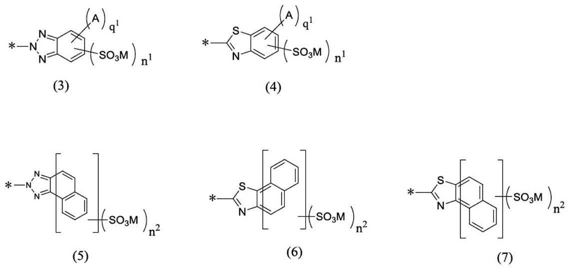
(上記式(3)及び式(4)中、Aは各々独立に、水素原子、ハロゲン基、ニトロ基、ヒドロキシ基、C1~4のアルキル基、C1~4のアルコキシ基、スルホ基を有するC1~4のアルキル基、ヒドロキシ基を有するC1~4のアルキル基、カルボキシ基を有するC1~4のアルキル基、スルホ基を有するC1~4のアルコキシ基、ヒドロキシ基を有するC1~4のアルコキシ基、カルボキシ基を有するC1~4のアルコキシ基からなる群から選択され、q1は0~4の整数を表し、上記式(3)~(7)におけるMは上記式(1)で定義された通りであり、n1及びn2は各々独立に0~3の整数を表し、上記式(3)~(7)中の*は、それぞれ、上記式(1)のX又はYにおける結合位置、又は、上記式(2)のZにおける結合位置を示す)。
[発明3]
上記式(1)におけるX及びYが各々独立に式(2)~(7)で表される置換基からなる群から選択され、式(2)が選択される場合にはZが式(3)~(7)で表される置換基からなる群から選択される、発明1又は2に記載の発光性化合物又はその塩。
[発明4]
上記式(1)における、X及びYがいずれも式(2)~(7)で表される置換基からなる群から選択され、式(2)が選択される場合にはZが式(3)~(7)で表される置換基からなる群から選択される、発明1又は2に記載の発光性化合物又はその塩。
[発明5]
上記式(1)における各mがいずれも0である、発明1~4のいずれかに記載の発光性化合物又はその塩。
[発明6]
sが0である、発明1~5のいずれかに記載の発光性化合物又はその塩。
[発明7]
sが1である、発明1~5のいずれかに記載の発光性化合物又はその塩。
[発明8]
上記式(1)が、下記式(1’)で表される発明7に記載の発光性化合物又はその塩。

(上記式(1’)中、X及びYはそれぞれ上記式(1)で定義された通りである)
[発明9]
偏光発光機能を有する、発明1~8のいずれかに記載の発光性化合物又はその塩を含む偏光発光素子。
[発明10]
上記発光性化合物又はその塩以外の有機染料又は蛍光染料を1種類以上さらに含む発明9に記載の偏光発光素子。
[発明11]
基材をさらに含む発明9又は10に記載の偏光発光素子。
[発明12]
上記基材がポリビニルアルコール樹脂又はその誘導体を含むフィルムである、発明11に記載の偏光発光素子。
[発明13]
発明9~12のいずれかに記載の偏光発光素子の少なくとも一方の面に透明保護膜を備える偏光発光板。
[発明14]
発明9~12のいずれかに記載の偏光発光素子又は発明13に記載の偏光発光板を備える表示装置。
本発明に係る発光性化合物又はその塩は、上記式(1)で表される。本明細書中、「発光性化合物又はその塩」を単に「発光性化合物」と略して記載することがある。
Mは各々独立に水素原子、金属イオン、又はアンモニウムイオンを表し、mは各々独立に0~2の整数を示し、sは0又は1である。
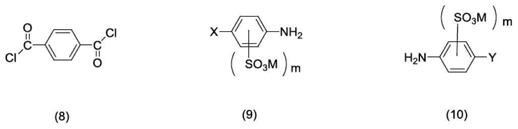
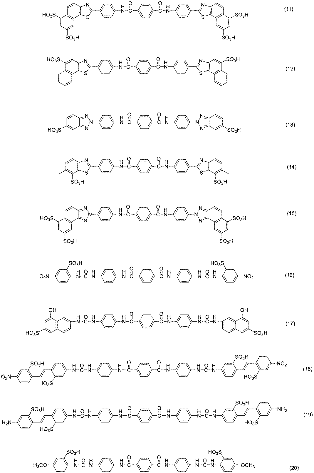

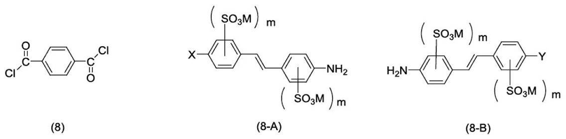
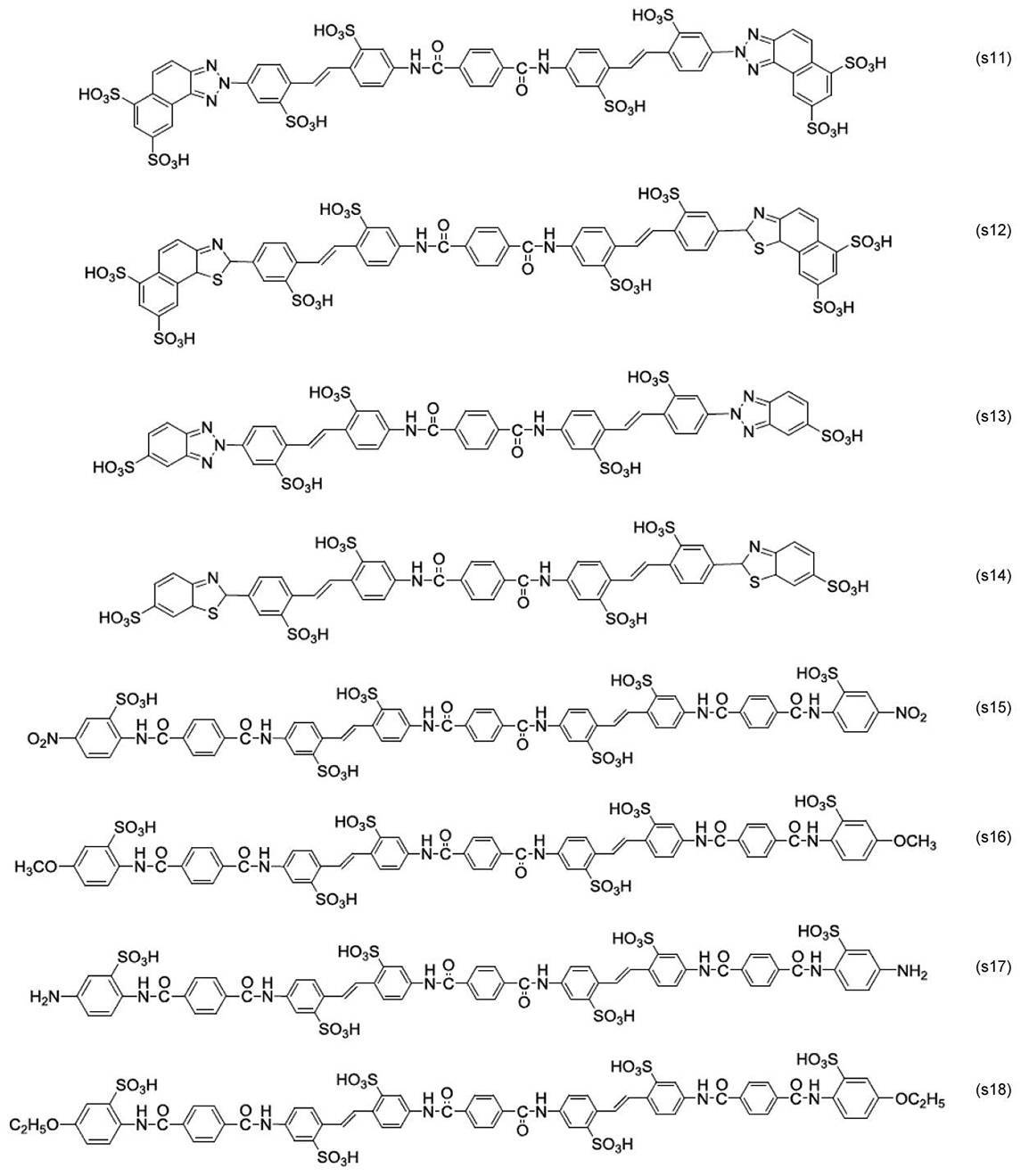
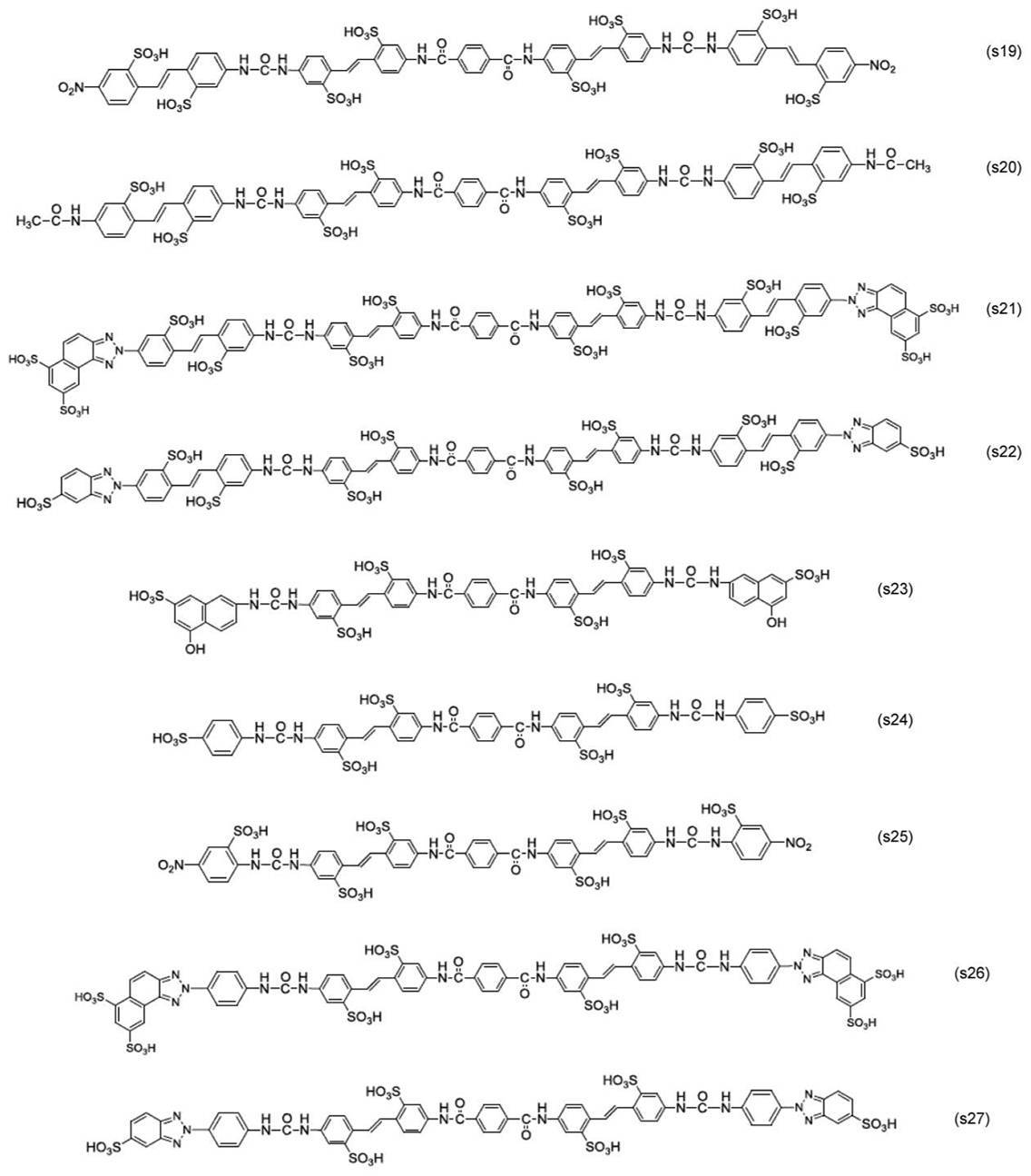
上記式(1)で表される発光性化合物又はその塩を含む偏光発光素子も本願発明に含まれる。
該偏光発光素子は、上記式(1)で表される発光性化合物又はその塩と、該偏光性化合物又はその塩が吸着及び配向された基材とを含む偏光発光素子であることが好ましい。該偏光発光素子は、上記式(1)で表される発光性化合物又はその塩を、1種単独又は複数種含むことができる。
次に、本発明に係る偏光発光素子の製造方法について説明する。製造方法は、以下の製法に限定されるものではないが、例えば、基材を準備する工程と、基材を膨潤液に浸漬させ、該基材を膨潤により延伸させる膨潤工程と、膨潤させた基材を少なくとも1種の上記式(1)で表される発光性化合物を含む染色溶液に含浸させ、基材に式(1)で表される発光性化合物を吸着させる染色工程と、式(1)で表される発光性化合物を吸着させた基材を、ホウ酸等の架橋剤を含有する溶液に浸漬し、式(1)で表される発光性化合物を基材中で架橋させる架橋工程と、式(1)で表される発光性化合物を架橋させた基材を一定の方向に一軸延伸して、式(1)で表される発光性化合物を一定の方向に配列させる延伸工程と、延伸させた基材を、洗浄液で洗浄する洗浄工程と、洗浄させた基材を乾燥させる乾燥工程を含んでいる。
上記式(1)で表される発光性化合物を含有させるための基材を準備する。該基材としては、例えば、市販のポリビニルアルコール系樹脂又はその誘導体を含むフィルムを用いてもよく、ポリビニルアルコール系樹脂を製膜することにより基材を作製してもよい。ポリビニルアルコール系樹脂の製膜方法は特に限定されるものではなく、例えば、含水ポリビニルアルコールを溶融押出する方法、流延製膜法、湿式製膜法、ゲル製膜法(ポリビニルアルコール水溶液を一旦冷却ゲル化した後、溶媒を抽出除去)、キャスト製膜法(ポリビニルアルコール水溶液を基板上に流し、乾燥)、及びこれらの組み合わせによる方法等、公知の製膜方法を採用することができる。ポリビニルアルコールの重合度としては1000~10000のものを用いることができ、当該重合度は、好ましくは1500~6000、より好ましくは2000~6000である。
次に、上述の基材に、膨潤処理を施す。膨潤処理は20~50℃の膨潤液に、基材を30秒~10分間浸漬させることにより行うことが好ましく、膨潤液は水であることが好ましい。膨潤液による基材の延伸倍率は、1.00~1.50倍に調整することが好ましく、1.10~1.35倍に調整することがより好ましい。
続いて、上記のような膨潤処理を施して得られた基材に、少なくとも1種の式(1)で表される発光性化合物又はその塩を吸着及び含浸させる。染色工程は、式(1)で表される発光性化合物又はその塩を基材に吸着及び含浸させる方法であれば特に限定されるものではないが、例えば、基材を、式(1)で表される発光性化合物又はその塩を含む染色溶液に浸漬させることが好ましく、また、基材に染色溶液を塗布することによって吸着させることもできる。染色溶液中の式(1)で表される発光性化合物又はその塩の濃度は、基材中に式(1)で表される発光性化合物又はその塩が十分に吸着されていれば特に限定されるものではないが、例えば、染色溶液中に0.0001~3質量%であることが好ましく、0.001~1質量%であることがより好ましい。
染色工程又は予備洗浄工程の後、基材に架橋剤を含有させることができる。基材に架橋剤を含有させる方法は、架橋剤を含む処理溶液に基材を浸漬させることが好ましく、一方で、当該処理溶液を基材に塗布又は塗工してもよい。処理溶液中の架橋剤としては、ホウ酸を含有する溶液を使用することが好ましい。処理溶液中の溶媒は、特に限定されるものではないが、水が好ましい。処理溶液中のホウ酸等の架橋剤の濃度は、0.1~15質量%であることが好ましく、0.1~10質量%であることがより好ましい。処理溶液の温度は、30~80℃が好ましく、40~75℃がより好ましい。また、この架橋工程の処理時間は30秒~10分が好ましく、1~6分がより好ましい。本発明に係る偏光発光素子の製造方法が、この架橋工程を有することにより、得られる偏光発光素子は、高い輝度と高い偏光度を有する光を発光しうる。このことは、従来技術において、耐水分性又は光透過性を改善する目的で使用されていたホウ酸の機能からは全く予期し得ない優れた作用である。また、架橋工程においては、必要に応じて、カチオン系高分子化合物を含む水溶液で、フィックス処理をさらに併せて行ってもよい。フィックス処理により、偏光色素の固定化が可能となる。このとき、カチオン系高分子化合物として、例えば、カチオン放出性化合物、ジシアン系化合物、ポリアミン系化合物、ポリカチオン系化合物、ジメチルジアリルアンモニウムクロライド・二酸化イオン共重合物、ジアリルアミン塩重合物、ジメチルジアリルアンモニウムクロライド重合物、アリルアミン塩の重合物、ジアルキルアミノエチルアクリレート四級塩重合物が使用され得る。ジシアン系化合物として例えばジシアンアミド・ホルマリン重合縮合物が挙げられる。ポリアミン系化合物として例えばジシアンジアミド・ジエチレントリアミン重縮合物が挙げられる。ポリカチオン系化合物として例えばエピクロロヒドリン・ジメチルアミン付加重合物が挙げられる。
架橋工程を行った後又はこれと同時に、延伸工程を実施する。延伸工程は、基材を一定の方向に一軸延伸することにより行われる。延伸方法は、湿式延伸法又は乾式延伸法のいずれであってもよい。延伸倍率は、3倍以上であることが好ましく、より好ましくは5~9倍である。
延伸工程を実施した後には、基材の表面に架橋剤の析出又は異物が付着することがあるため、基材の表面を洗浄する洗浄工程を行うことができる。洗浄時間は1秒~5分が好ましい。洗浄方法は、基材を洗浄液に浸漬することが好ましく、一方で、洗浄液を基材に塗布又は塗工することによって洗浄することもできる。洗浄液としては、水が好ましい。洗浄処理は一段階で実施しても、2段階以上の多段処理で実施してもよい。洗浄工程の洗浄溶の温度は、特に限定されるものではないが、通常、5~50℃、好ましくは10~40℃であり、常温であってよい。
洗浄工程の後、基材の乾燥工程を行うことが好ましい。乾燥処理は、自然乾燥により行うことができるものの、より乾燥効率を高めるため、ロールによる圧縮やエアーナイフ又は吸水ロール等による表面の水分除去等により行うことが可能であり、さらには、送風乾燥を行うことも可能である。乾燥処理の温度は、20~100℃であることが好ましく、60~100℃であることがより好ましい。乾燥時間は、30秒~20分であることが好ましく、5~10分であることがより好ましい。
上記偏光発光素子を備える偏光発光板も本願発明に含まれる。
本発明に係る偏光発光板は、上記の偏光発光素子の少なくとも一方の面に透明保護膜を有していることが好ましい。透明保護膜は、偏光発光素子の耐水性や取扱性等を向上させるために使用される。そのため、このような透明保護膜は、本発明に係る偏光発光素子が示す偏光作用に何ら影響を与えるものではないことが好ましい。
上記偏光発光素子又は偏光発光板を備える表示装置(ディスプレイ)も本願発明に含まれる。
上記表示装置は、紫外域~可視域の光、例えば紫外域~近紫外可視域の光、具体的には300~430nmの光を照射することによって偏光発光作用を示し、この作用を利用することによって表示が可能となる。本発明に係る表示装置は、可視光領域で高い透過率を有しているため、従来の偏光板のような可視光領域の透過率の低下がないか、透過率の低下があっても、従来の偏光板の透過率よりも透過率の低下は著しく小さい。例えば、従来の偏光板であるヨウ素系偏光板や、他の染料を使用した染料系偏光板は、偏光度をほぼ100%にするためには、可視光領域での視感度補正が35~45%程度である。その理由としては、従来の偏光板は、光の吸収軸として縦軸と横軸の両方を有しているが、ほぼ100%の偏光度を得るために縦軸又は横軸の一方の入射光を吸収する、すなわち、一方の軸では光を吸収し、他方の軸では光を透過することによって偏光が生じる。このような場合、一方の軸での光は吸収されて透過しないことから、必然的に透過率は50%以下なってしまう。また、従来、延伸されたフィルム中で二色性色素を配向させて偏光板を作製しているが、必ずしも二色性色素が100%配向しているわけではなく、また、光の透過軸に対しても若干吸収成分を有している。そのため、物質の表面反射によって透過率が約45%以下でないとほぼ100%の偏光度は実現できない、つまりは、透過率を低下させなければ高い偏光度を実現することができなかった。それに対して、本発明に係る偏光発光素子及び偏光発光板は、紫外域~近紫外可視域の光、例えば300~430nmに光の吸収する軸(その偏光機能)がある、すなわち、紫外域~近紫外可視域の光、例えば300~430nmに光の吸収作用があり、可視光領域に偏光した光を発光する偏光発光作用を示す一方で、可視光領域ではほとんど光を吸収しないため、可視光領域での透過率は非常に高くなる。さらに、可視光領域では、偏光発光作用を示すため、従来の偏光板を用いるよりも光の損失は少なく、つまり、従来の偏光板のような透過率の低下は非常に少ない。そのため、本発明に係る偏光発光素子及び偏光発光板を使用した表示装置、例えば、液晶ディスプレイは、従来の偏光板を備える液晶ディスプレイよりも高い輝度が得られる。さらに、本発明に係る偏光発光素子及び偏光発光板を使用した表示装置は、透明性が高いため、液晶ディスプレイでありながら、ほぼ透明なディスプレイが得られる。また、文字、画像の表示時には偏光発光光が透過するように設計できるため、透明な液晶ディスプレイでありながらも表示可能なディスプレイが得られる、すなわち、透明なディスプレイに文字等が表示可能なディスプレイが得られる。したがって、本発明に係る表示装置は、光損失がない透明な液晶ディスプレイ、特に、シースルーディスプレイを得ることができる。
(合成例)
式(25)で表される化合物 84部を600部の水に加え60℃まで加熱し、pH6~7になるように調整しながら25%苛性ソーダを加えて、前記化合物を溶解させた。テレフタル酸ジクロリド 20.2部を、1時間程度かけて少しずつ加えた。全て添加した後、60℃で1時間撹拌して、反応させた。反応終了後、室温まで放冷して濾過し、得られた固体を70℃で乾燥することで、式(15)で表される化合物 67.4部を得た。

厚さ75μmのポリビニルアルコールフィルム(クラレ社製VF-PS#7500)を40℃の水に3分間浸漬して、フィルムを膨潤させた。膨潤して得られたフィルムを、合成例1で得られた式(15)で表される化合物 0.2質量部と、芒硝1.0質量部と、水1000質量部とを含む45℃の水溶液に、4分間浸漬して式(15)で表される化合物をフィルムに含ませた。式(15)で表される化合物を含ませたフィルムを50℃の3%濃度ホウ酸水溶液中で5分間かけて5倍に延伸した。延伸して得られたフィルムを、緊張状態を保ったまま常温の水で20秒間水洗し、70℃で乾燥して偏光発光素子を得た。得られた偏光発光素子の両面を、1.5規定の水酸化ナトリウムで表面がケン化処理された厚さ60μmの紫外線吸収剤を含有しないトリアセチルセルロースフィルム(富士フイルム社製 ZRD-60)を、4質量% ポリビニルアルコール(日本酢ビ・ポバール社製 NH-26)水溶液を接着剤としてラミネートして偏光発光板を得て実施例1の測定試料とした。
なお、偏光発光素子に紫外線吸収剤を含有しないトリアセチルセルロースフィルム(富士フイルム社製 ZRD-60)を貼合しても、なんら偏光発光素子の光学特性に影響するものではなかった。以下の実施例、比較例でも偏光発光素子に紫外線吸収剤を含有しないトリアセチルセルロースフィルムを貼合したが、同様になんら光学特性に影響を与えるものではなかった。
式(26)で表される化合物 60部を600部の水に加え60℃まで加熱し、pH6~7になるように調整しながら25%苛性ソーダを加えて、前記化合物を溶解させた。テレフタル酸ジクロリド 20部を、1時間程度かけて少しずつ加えた。全て添加した後、60℃で1時間撹拌して、反応させた。反応終了後、室温まで放冷して濾過し、得られた固体を70℃で乾燥することで、式(14)で表される化合物 51.5部を得た。実施例1の偏光発光素子及び偏光発光板の作製において、式(15)で表される化合物に代えて式(14)で表される化合物を用いた以外は同様にして、実施例2の測定試料を得た。
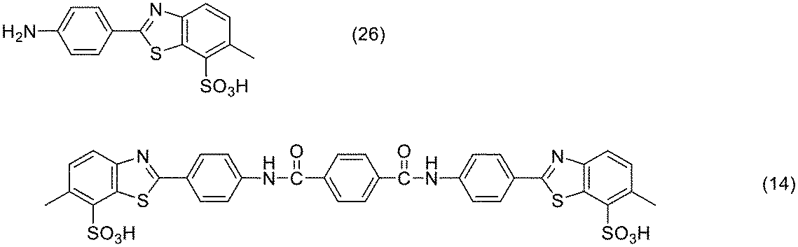
式(27)で表される化合物 21.8部及び式(28)で表される化合物 10.8部を水400部に加え、pH6~7になるように調整しながら25%苛性ソーダを加えて、前記化合物を溶解し、クロロギ酸フェニル 15.6部を50~70℃で6時間撹拌しウレイド化した。塩化ナトリウムで塩析し、ろ過して、70℃で乾燥し、式(29)で表されるウレイド化合物 24.6部を得た。得られた式(29)で表される化合物 24.6部を500部の水に加え60℃まで加熱し、pH6~7になるように調整しながら25%苛性ソーダを加えて、前記化合物を溶解させた。テレフタル酸ジクロリド 7.0部を、1時間程度かけて少しずつ加えた。全て添加した後、60℃で1時間撹拌して、反応させた。反応終了後、室温まで放冷して濾過し、得られた固体を70℃で乾燥することで、式(16)で表される化合物と式(30)で表される化合物との混合物 5.7部を得た。実施例1の偏光発光素子及び偏光発光板の作製において、式(15)で表される化合物に代えて式(16)で表される化合物と式(30)で表される化合物との混合物を用いた以外は同様にして、実施例3の測定試料を得た。

式(28)で表される化合物 21.8部を水400部に加え、水酸化ナトリウムを加えながら溶解し、テレフタル酸ジクロリド 20.2部を1時間程度かけて少しずつ加えた。全て添加した後、60℃で1時間撹拌して、反応させた。反応終了後、4-ニトロ-4’-アミノスチルベン-2,2’-ジスルホン酸 80.0部を加え、水酸化ナトリウムを加えながら溶解し、クロロギ酸フェニル 31.2部を1時間程度かけて少しずつ加えた。全て添加した後、60℃で1時間撹拌して、反応させた。反応終了後、室温まで放冷して濾過し、得られた固体を70℃で乾燥することで式(18)で表される化合物と式(31)で表される化合物との混合物 12.4部を得た。実施例1の偏光発光素子及び偏光発光板の作製において、式(15)で表される化合物に代えて式(18)で表される化合物と式(31)で表される化合物との混合物を用いた以外は同様にして、実施例4の測定試料を得た。

4-ニトロ-4’-アミノスチルベン-2,2’-ジスルホン酸 40.0部及び式(28)で表される化合物 10.8部を水400部に加え、水酸化ナトリウムを加えながら溶解し、テレフタル酸ジクロリド 20.2部を1時間程度かけて少しずつ加えた。全て添加した後、60℃で1時間撹拌して、反応させた。反応終了後、4-ニトロ-4’-アミノスチルベン-2,2’-ジスルホン酸 40.0部を加え、水酸化ナトリウムを加えながら溶解し、クロロギ酸フェニル 15.6部を1時間程度かけて少しずつ加えた。全て添加した後、60℃で1時間撹拌して、反応させた。反応終了後、室温まで放冷して濾過し、得られた固体を70℃で乾燥することで式(22)で表される化合物と式(32)で表される化合物との混合物 8.9部を得た。実施例1の偏光発光素子及び偏光発光板の作製において、式(15)で表される化合物に代えて式(22)で表される化合物と式(32)で表される化合物との混合物を用いた以外は同様にして、実施例5の測定試料を得た。

式(s28)で表される化合物 120.4部を500部の水に加え60℃まで加熱し、pH6~7になるように調整しながら25%苛性ソーダを加えて、前記化合物を溶解させた。テレフタル酸ジクロリド 20.2部を、1時間程度かけて少しずつ加えた。全て添加した後、60℃で1時間撹拌して、反応させた。反応終了後、室温まで放冷して濾過し、得られた固体を70℃で乾燥することで、式(s29)で表される化合物 93.4部を得た。実施例1の偏光発光素子及び偏光発光板の作製において、式(15)で表される化合物に代えて式(s29)で表される化合物を用いた以外は同様にして、実施例s1の測定試料を得た。

式(s30)で表される化合物114部を、500部の水に加え60℃まで加熱し、25%苛性ソーダをpH6~7になるように調整しながら加えて、前記化合物を溶解させた。テレフタル酸ジクロリド 20.2部を、1時間程度かけて少しずつ加えた。全て添加した後、60℃で1時間撹拌して、反応させた。反応終了後、室温まで放冷して濾過し、得られた固体を70℃で乾燥することで、式(s14)で表される化合物 103部を得た。実施例1の偏光発光素子及び偏光発光板の作製において、式(15)で表される化合物に代えて式(s14)で表される化合物を用いた以外は同様にして、実施例s2の測定試料を得た。
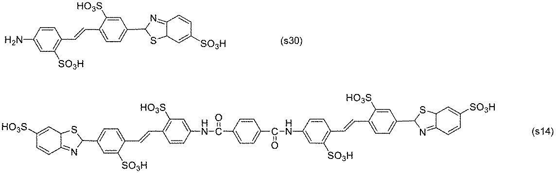
4-ニトロ-4’-アミノスチルベン-2,2’-ジスルホン酸 40部と式(s28)で表される化合物 60.2部を、500部の水に加え60℃まで加熱し、pH6~7になるように調整しながら25%苛性ソーダを加えて、前記化合物を溶解させた。テレフタル酸ジクロリド 20.2部を、1時間程度かけて少しずつ加えた。全て添加した後、60℃で1時間撹拌して、反応させた。反応終了後、室温まで放冷して濾過し、得られた固体を70℃で乾燥することで、式(s31)で表される化合物 84.1部を得た。実施例1の偏光発光素子及び偏光発光板の作製において、式(15)で表される化合物に代えて式(s31)で表される化合物を用いた以外は同様にして、実施例s3の測定試料を得た。

式(s32)で表される化合物 21.8重量部と4,4’-ジアミノスチルベン-2,2’-ジスルホン酸 37重量部と500部の水に加え60℃まで加熱し、pH6~7になるように調整しながら25%苛性ソーダを加えて、前記化合物を溶解させた。テレフタル酸ジクロリド 20.2部を、1時間程度かけて少しずつ加えた。全て添加した後、60℃で1時間撹拌して、反応させた。反応終了後、室温まで放冷して濾過し、得られた固体を70℃で乾燥することで、式(s15)及び式(s33)で表される化合物との混合物 24.5部を得た。実施例1の偏光発光素子及び偏光発光板の作製において、式(15)で表される化合物に代えて式(s15)及び式(s33)で表される化合物の混合物を用いた以外は同様にして、実施例s4の測定試料を得た。
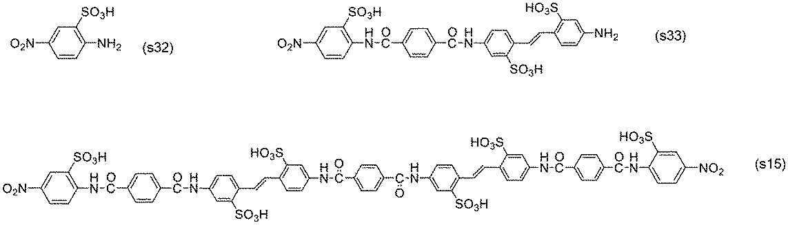
4-ニトロ-4’-アミノスチルベン-2,2’-ジスルホン酸 40部を500部の水に加え60℃まで加熱し、pH6~7になるように調整しながら25%苛性ソーダを加えて、前記化合物を溶解させた。クロロギ酸フェニル 15.6部と44’-ジアミノスチルベン-2,2’-ジスルホン酸 37部を、1時間程度かけて少しずつ加えた。全て添加した後、60℃で1時間撹拌した。得られた溶液にテレフタル酸ジクロリド 10.1部を1時間程度かけて少しずつ加え、全て添加した後、60℃で1時間撹拌して、反応させた。反応終了後、室温まで放冷して濾過し、得られた固体を70℃で乾燥することで、式(s19)で表される化合物 22.3部を得た。実施例1の偏光発光素子及び偏光発光板の作製において、式(15)で表される化合物に代えて式(s19)で表される化合物を用いた以外は同様にして、実施例s5の測定試料を得た。

実施例1の偏光発光素子及び偏光発光板の作製において、式(15)で表される化合物に代えて特開平4-226162号公報に記載されている式(c1)で表される化合物を用いた以外は同様にして、比較例1の測定試料を得た。
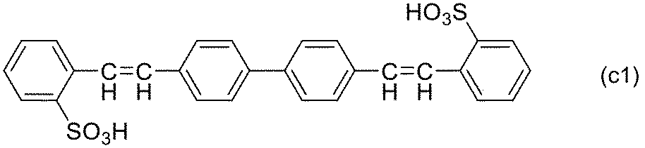
実施例1の偏光発光素子及び偏光発光板の作製において、式(15)で表される化合物に代えて式(c2)で表される化合物であるC.I.Direct Yellow 4を用いた以外は同様にして、比較例2の測定試料を得た。

実施例1の偏光発光素子及び偏光発光板の作製において、式(15)で表される化合物に代えて式(c3)で表される化合物を用いた以外は同様にして、比較例3の測定試料を得た。
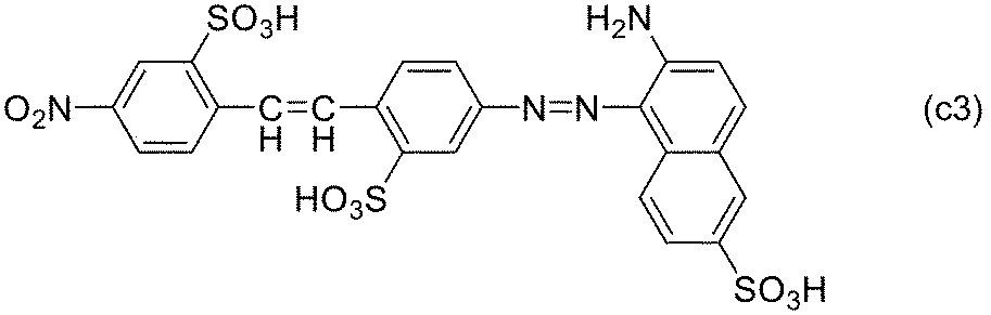
実施例1~5及びs1~s5並びに比較例1~3で得られた測定試料を使用して、評価を次のようにして行った。
各測定試料の単体透過率Ts(%)、平行位透過率Tp(%)、及び直交位透過率Tc(%)を、分光光度計(日立製作所社製「U-4100」)を用いて測定した。ここで、単体透過率Ts(%)は、測定試料を1枚で測定した際の各波長の透過率である。平行位透過率Tp(%)は、2枚の測定試料をその吸収軸方向が平行となるように重ね合せて測定した各波長の分光透過率である。直交位透過率Tc(%)は、2枚の測定試料をその吸収軸が直交するように重ね合せて測定した分光透過率である。各透過率の測定は、220~780nmの波長にわたって行った。
各測定試料の偏光度ρ(%)を、以下の式(I)に平行透過率Tp及び直交透過率Tcを代入して求めた。

各測定試料の視感度に補正された単体透過率Ys(%)は、可視域における400~700nmの波長領域で、所定波長間隔dλ(ここでは5nm)おきに求めた上記単体透過率Tsを、JIS Z 8722:2009に従って視感度に補正して得られた透過率である。具体的には、単体透過率Tsを式(II)に代入して視感度補正単体透過率Ysを算出した。なお、下記式(II)中、Pλは標準光(C光源)の分光分布を表し、yλは2度視野等色関数を表す。
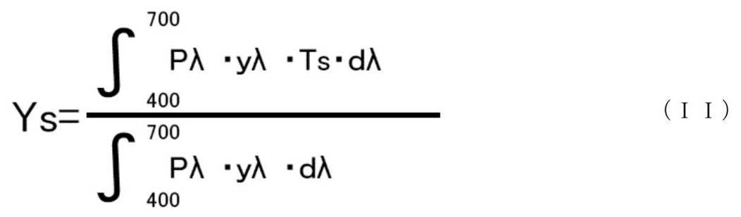
光源として、紫外線LED 375nmハンドライトタイプ ブラックライト(日亜化学工業社製「PW-UV943H-04」)を用い、紫外線透過及び可視光カットフィルター(五鈴精工硝子社製「IUV-340」)を光源に設置し可視光をカットした。各実施例及び比較例で得られた測定試料を設置し、測定試料が発光している偏光した光を分光放射照度計(ウシオ電機社製「USR-40」)を用いて測定するに際し、可視域及び紫外に偏光機能を有する偏光板(ポラテクノ社製「SKN-18043P」、厚さ180μm、Ysは43%)を分光放射照度計の受光部に設置し、各実施例及び比較例で得られた測定試料の偏光発光光量を測定した。すなわち、光源からの光が、紫外線透過及び可視光カットフィルター、測定試料、可視域及び紫外に偏光を有する偏光板の順に通過し、分光放射照度計に入射するように配置して測定した。その際に、測定試料の紫外線の吸収が最大になる吸収軸と、可視域及び紫外に偏光を有する偏光板(ポラテクノ社製「SKN-18043P」)の吸収軸方向が平行となるように重ね合せて測定した各波長の分光発光量をLw(弱発光軸)、測定試料の紫外線の吸収が最大になる吸収軸と、可視域及び紫外に偏光を有する偏光板(ポラテクノ社製「SKN-18043P」)の吸収軸方向が直交となるように重ね合せて測定した各波長の分光発光量をLs(強発光軸)として、Lw及びLsを測定した。測定試料と一般的な偏光板との吸収軸が平行な場合と、直交の場合との可視域で発光された光のエネルギー量を確認することで、可視域である400~700nmにおいて偏光発光光の評価を行った。
スガ試験機社製 SX-75を用いて、照射照度60W、環境温度50℃、及び相対湿度30%RHにて500時間光照射を行い、耐光性試験を行った。その際の各波長のLs及びLwの変化を確認した。


実施例1~5及びs1~s5において得られた偏光発光板を、105℃の環境で1000時間と、60度かつ相対湿度90%の環境で1000時間置き、耐久性試験を実施したところ、偏光度の低下、及び、偏光した光の発光の変化は見られなかった。このことから実施例1~5及びs1~s5の偏光発光素子及び偏光発光板は苛酷な環境下においても高い耐久性を有していることが示された。
Claims (14)
- 下記式(1)で表される発光性化合物又はその塩:

(式(1)中、(i)X及びYは各々独立に、上記式(2)で表される基、窒素原子若しくは硫黄原子を含む複素環基、ニトロ基からなる群から選択される基を少なくとも含むが、X及びYのいずれもニトロ基である場合を除く;又は(ii)X及びYの少なくとも一方が(両方の場合には各々独立に)、ニトロ基、置換基を有してもよいアミノ基、置換基を有してもよいC1~4のアルキル基、置換基を有してもよいC1~4のアルコキシ基、置換基を有してもよい芳香族基、置換基を有してもよい酸素原子、窒素原子若しくは硫黄原子を含む複素環基、又は式(2)で表される基であって、X又はYが上記選択される基でない場合には該X又はYは任意の置換基から選択され、
Mは各々独立に水素原子、金属イオン、又はアンモニウムイオンを表し、mは各々独立に0~2の整数を示し、sは0又は1であり、
式(2)中、※は、式(1)におけるX及び/又はYにおける結合位置を示し、Zは置換基を有してもよいフェニル基、置換基を有してもよいナフチル基、置換基を有してもよいスチルベン基、置換基を有してもよいベンゾイル基、及び置換基を有してもよい複素環基からなる群から選択され、tは0又は1の整数を表す)。 - 上記式(1)におけるX、Y、並びにX及びYの少なくとも一方が上記式(2)で表される場合の上記式(2)におけるZ、の少なくとも1つが下記式(3)~(7)で表される置換基からなる群から選択される、請求項1に記載の発光性化合物。

(上記式(3)及び式(4)中、Aは各々独立に、水素原子、ハロゲン基、ニトロ基、ヒドロキシ基、C1~4のアルキル基、C1~4のアルコキシ基、スルホ基を有するC1~4のアルキル基、ヒドロキシ基を有するC1~4のアルキル基、カルボキシ基を有するC1~4のアルキル基、スルホ基を有するC1~4のアルコキシ基、ヒドロキシ基を有するC1~4のアルコキシ基、カルボキシ基を有するC1~4のアルコキシ基からなる群から選択され、q1は0~4の整数を表し、上記式(3)~(7)におけるMは上記式(1)で定義された通りであり、n1及びn2は各々独立に0~3の整数を表し、上記式(3)~(7)中の*は、それぞれ、上記式(1)のX又はYにおける結合位置、又は、上記式(2)のZにおける結合位置を示す)。 - 上記式(1)におけるX及びYが各々独立に式(2)~(7)で表される置換基からなる群から選択され、式(2)が選択される場合にはZが式(3)~(7)で表される置換基からなる群から選択される、請求項1又は2に記載の発光性化合物又はその塩。
- 上記式(1)における、X及びYがいずれも式(2)~(7)で表される置換基からなる群から選択され、式(2)が選択される場合にはZが式(3)~(7)で表される置換基からなる群から選択される、請求項1又は2に記載の発光性化合物又はその塩。
- 上記式(1)における各mがいずれも0である、請求項1~4のいずれかに記載の発光性化合物又はその塩。
- sが0である、請求項1~5のいずれかに記載の発光性化合物又はその塩。
- sが1である、請求項1~5のいずれかに記載の発光性化合物又はその塩。
- 上記式(1)が、下記式(1’)で表される請求項7に記載の発光性化合物又はその塩。

(上記式(1’)中、X及びYはそれぞれ上記式(1)で定義された通りである) - 偏光発光機能を有する、請求項1~8のいずれかに記載の発光性化合物又はその塩を含む偏光発光素子。
- 上記発光性化合物又はその塩以外の有機染料又は蛍光染料を1種類以上さらに含む請求項9に記載の偏光発光素子。
- 基材をさらに含む請求項9又は10に記載の偏光発光素子。
- 上記基材がポリビニルアルコール樹脂又はその誘導体を含むフィルムである、請求項11に記載の偏光発光素子。
- 請求項9~12のいずれかに記載の偏光発光素子の少なくとも一方の面に透明保護膜を備える偏光発光板。
- 請求項9~12のいずれかに記載の偏光発光素子又は請求項13に記載の偏光発光板を備える表示装置。
Priority Applications (2)
| Application Number | Priority Date | Filing Date | Title |
|---|---|---|---|
| CN202080044268.9A CN114072392B (zh) | 2019-07-12 | 2020-07-10 | 发光性化合物或其盐,以及含有该化合物的偏光发光元件、偏光发光板及显示装置 |
| JP2021533043A JP7556855B2 (ja) | 2019-07-12 | 2020-07-10 | 発光性化合物又はその塩、並びにこれを含む偏光発光素子、偏光発光板、及び表示装置 |
Applications Claiming Priority (4)
| Application Number | Priority Date | Filing Date | Title |
|---|---|---|---|
| JP2019-130391 | 2019-07-12 | ||
| JP2019-130395 | 2019-07-12 | ||
| JP2019130395 | 2019-07-12 | ||
| JP2019130391 | 2019-07-12 |
Publications (1)
| Publication Number | Publication Date |
|---|---|
| WO2021010331A1 true WO2021010331A1 (ja) | 2021-01-21 |
Family
ID=74210870
Family Applications (1)
| Application Number | Title | Priority Date | Filing Date |
|---|---|---|---|
| PCT/JP2020/027058 Ceased WO2021010331A1 (ja) | 2019-07-12 | 2020-07-10 | 発光性化合物又はその塩、並びにこれを含む偏光発光素子、偏光発光板、及び表示装置 |
Country Status (4)
| Country | Link |
|---|---|
| JP (1) | JP7556855B2 (ja) |
| CN (1) | CN114072392B (ja) |
| TW (1) | TWI826705B (ja) |
| WO (1) | WO2021010331A1 (ja) |
Citations (2)
| Publication number | Priority date | Publication date | Assignee | Title |
|---|---|---|---|---|
| GB1254214A (en) * | 1968-03-15 | 1971-11-17 | Agfa Gevaert Ag | Photographic silver-dye-bleach material |
| JP2008033275A (ja) * | 2006-06-16 | 2008-02-14 | Mitsubishi Chemicals Corp | 異方性膜用材料 |
Family Cites Families (5)
| Publication number | Priority date | Publication date | Assignee | Title |
|---|---|---|---|---|
| US6444091B1 (en) * | 2000-12-20 | 2002-09-03 | Nalco Chemical Company | Structurally rigid nonionic and anionic polymers as retention and drainage aids in papermaking |
| JP4105890B2 (ja) * | 2002-04-19 | 2008-06-25 | 富士フイルム株式会社 | 光学活性ポリエステル/アミド、光反応型キラル剤、液晶組成物、液晶カラーフィルター、光学フィルム及び記録媒体、並びに液晶の螺旋構造を変化させる方法、液晶の螺旋構造を固定化する方法 |
| US8361495B2 (en) | 2009-12-23 | 2013-01-29 | International Business Machines Corporation | Antimicrobial polymers and methods of manufacture thereof |
| US9187663B2 (en) | 2013-03-21 | 2015-11-17 | Xerox Corporation | Ink composition and method of jetting ink |
| CN110832363B (zh) * | 2017-07-28 | 2022-07-22 | 日本化药株式会社 | 偏光发光元件、偏光发光板、显示装置及偏光发光元件的制造方法 |
-
2020
- 2020-07-10 CN CN202080044268.9A patent/CN114072392B/zh active Active
- 2020-07-10 JP JP2021533043A patent/JP7556855B2/ja active Active
- 2020-07-10 WO PCT/JP2020/027058 patent/WO2021010331A1/ja not_active Ceased
- 2020-07-10 TW TW109123409A patent/TWI826705B/zh active
Patent Citations (2)
| Publication number | Priority date | Publication date | Assignee | Title |
|---|---|---|---|---|
| GB1254214A (en) * | 1968-03-15 | 1971-11-17 | Agfa Gevaert Ag | Photographic silver-dye-bleach material |
| JP2008033275A (ja) * | 2006-06-16 | 2008-02-14 | Mitsubishi Chemicals Corp | 異方性膜用材料 |
Non-Patent Citations (3)
| Title |
|---|
| DATABASE Registry STN; 18 April 2008 (2008-04-18), XP055790499, Database accession no. RN 1015660-44-2 * |
| DATABASE Registry STN; 25 March 2003 (2003-03-25), XP055790505, Database accession no. RN 500536-07-2 * |
| PHOON, CHEE WEE ET AL.: "Biological Evaluation of Hepatitis C Virus Helicase Inhibitors", BIOORGANIC & MEDICINAL CHEMISTRY LETTERS, vol. 11, no. 13, 2001, pages 1647 - 1650, XP055086365, ISSN: 0960-894X, DOI: 10.1016/S0960-894X(01)00263-3 * |
Also Published As
| Publication number | Publication date |
|---|---|
| JPWO2021010331A1 (ja) | 2021-01-21 |
| TW202113030A (zh) | 2021-04-01 |
| TWI826705B (zh) | 2023-12-21 |
| CN114072392A (zh) | 2022-02-18 |
| JP7556855B2 (ja) | 2024-09-26 |
| CN114072392B (zh) | 2025-05-02 |
Similar Documents
| Publication | Publication Date | Title |
|---|---|---|
| JP6317335B2 (ja) | 高透過率を有する無彩色な染料系偏光素子及び偏光板 | |
| JP7287889B2 (ja) | 偏光発光素子、偏光発光板、表示装置及び偏光発光素子の製造方法 | |
| JP6317334B2 (ja) | 無彩色な染料系偏光素子、及び偏光板 | |
| JP6317333B2 (ja) | 無彩色な偏光素子、及び偏光板 | |
| JPWO2019058758A1 (ja) | 光学システム及び表示装置 | |
| JPWO2019022211A1 (ja) | スチルベン系化合物又はその塩、並びに、偏光膜、偏光板及び表示装置 | |
| KR20170013889A (ko) | 고투과 고편광도인 무채색 편광판 | |
| CN111448493A (zh) | 无色彩的偏光元件、以及使用该偏光元件的无色彩偏光板及显示装置 | |
| KR20170131340A (ko) | 편광소자 및 편광판 | |
| JP7522738B2 (ja) | 発光性化合物又はその塩、ならびにこれを用いた偏光発光素子、偏光発光板、及び表示装置 | |
| WO2021166907A1 (ja) | 光学システム及びそれを備えた光学装置 | |
| KR101891523B1 (ko) | 염료계 편광소자 및 편광판 | |
| JP7556855B2 (ja) | 発光性化合物又はその塩、並びにこれを含む偏光発光素子、偏光発光板、及び表示装置 | |
| JP7556856B2 (ja) | 発光性化合物又はその塩、並びにこれを含む偏光発光素子、偏光発光板、及び表示装置 | |
| JP7479136B2 (ja) | 偏光発光素子、偏光発光板、並びにそれを用いた表示装置 | |
| JP7336964B2 (ja) | 光学制御システム | |
| WO2021010351A1 (ja) | 発光性化合物又はその塩を用いた偏光発光素子、偏光発光板、及び表示装置 | |
| WO2021106798A1 (ja) | 偏光発光素子、偏光発光板、及び表示装置 | |
| HK1217122B (en) | Achromatic dye-based polarization element, and polarization plate | |
| HK1216672B (en) | Achromatic dye-based highly-transmissive polarization element, and polarization plate |
Legal Events
| Date | Code | Title | Description |
|---|---|---|---|
| 121 | Ep: the epo has been informed by wipo that ep was designated in this application |
Ref document number: 20839583 Country of ref document: EP Kind code of ref document: A1 |
|
| ENP | Entry into the national phase |
Ref document number: 2021533043 Country of ref document: JP Kind code of ref document: A |
|
| NENP | Non-entry into the national phase |
Ref country code: DE |
|
| 122 | Ep: pct application non-entry in european phase |
Ref document number: 20839583 Country of ref document: EP Kind code of ref document: A1 |
|
| WWG | Wipo information: grant in national office |
Ref document number: 202080044268.9 Country of ref document: CN |